Evaluación global de las mejores prácticas de relleno de ... · stoping operations (e.g. large...
46
Evaluación global de las mejores prácticas de relleno de minas subterráneas Presented by: Dr. David Stone, P.E. President MineFill Services, Inc.
Transcript of Evaluación global de las mejores prácticas de relleno de ... · stoping operations (e.g. large...

Evaluación global de las mejores prácticas de relleno de minas
subterráneas
Presented by:
Dr. David Stone, P.E. President
MineFill Services, Inc.

Presentation Overview
Backfill in the Mining Cycle Common Roles for Mine Backfills History of Mine Fills Early years for Paste Fills The science of Paste Fills Backfilling Best Practices Adoption of Paste Fills globally Role of the Mining Stakeholder Recent Events The new reality and future of Mine Fills

A Quick History of Modern Backfills
1970’s - in the beginning we had hydraulic fill 1980’s - there was a need for a better fill – early attempts to make paste Late 1980’s to early 1990’s - the birth of paste rheology 1990’s –
Rapid evolution of thickening and dewatering equipment Improvements in pumping Improvements in the science of rheology
2000’s to now – paste backfill accepted globally

Backfill in the Mining Cycle
Drill
Blast
Muck Barricade
Fill
Cure

Common Types of Backfill in use Today
ROCKFILLS HYDRAULIC FILLS PASTE FILLS
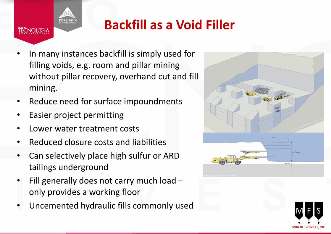
Backfill as a Void Filler
• In many instances backfill is simply used for filling voids, e.g. room and pillar mining without pillar recovery, overhand cut and fill mining.
• Reduce need for surface impoundments
• Easier project permitting
• Lower water treatment costs
• Reduced closure costs and liabilities
• Can selectively place high sulfur or ARD tailings underground
• Fill generally does not carry much load – only provides a working floor
• Uncemented hydraulic fills commonly used

Fill for Pillar Recovery
Most mines use backfill for increased ore recovery
Works best in primary stopes in open stoping operations (e.g. large blasthole stopes, longhole, vertical crater retreat, sub-level stoping etc)
Cement must be added to provide stable vertical faces during exposure of fills
Uncemented fills in secondaries unless plan to undercut
Typical strengths > 0.5 Mpa Can encompass all types of fills: CRF,
CHF, CPF Fills generally not designed to carry
external loads (other than self-weight)
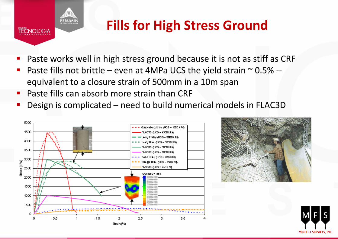
Fills for High Stress Ground
Paste works well in high stress ground because it is not as stiff as CRF Paste fills not brittle – even at 4MPa UCS the yield strain ~ 0.5% --
equivalent to a closure strain of 500mm in a 10m span Paste fills can absorb more strain than CRF Design is complicated – need to build numerical models in FLAC3D

The History of Mine Backfills
Backfill has been used in mining since the 1500’s. Several mines in Mexico go back to the days of Spanish conquistadors.
Historical fills included any kind of trash, timbers, or mine waste to fill mine voids and provide a working floor for overhand mining
Between 1950 and 1970 the use of hydraulic (sand) fill (HF) expanded rapidly due to the availability of tailings
Low cost Portland cement introduced in the 1960’s allowed cemented HF which allowed recovery of pillars
However HF did not come without problems Massive volumes of dirty water Very high cement consumption
As comminution technology improved grinds got finer and there was less sand to make HF

History (continued)
Very early “paste” systems can attribute their beginnings to the Tailspinner™ manufactured by Joy Manufacturing Company of Cambridge, ON
Centrifuge produced a “filter cake” – no more than 25% c/w water
Solids were pneumatically stowed or pumped into stope
Patent granted in July 1978 to W.R. Wayment First placed into use in South Africa in Wits basin
as a prototype Tailspinners formed the basis of the first paste
plants in Canada at Dome, South Porcupine However its adoption was limited by its capacity
~ 15 tph

The Birth of Paste Backfills – 1980’s
Prior to 1985 the rheology of paste mixes was very poorly understood. Verkerk in 1988 was the first to examine and publish rheograms for tailings mixes and open
the door to understanding paste flow and paste pumping Verkerk also understood that paste behaves as a non-Newtonian fluid governed by viscosity
and yield stress Early paste systems such as Lucky Friday (1988) had to learn by trial and error By early 1990 a number of mining companies and researchers were working on paste
rheology -- • Mt Isa in Australia • Inco in Canada • Universities such as McGill, Laval in Canada

Paste Rheology becomes a Science
The starting point for understanding the rheology of paste mixes that could be pumped came from the concrete industry (INCO circa 1979 – Dave Landriault): Definition of paste – a solids concentration with point to point particle contacts.
Non-settling, non-segregating, non-Newtonian Rule-of-thumb – paste must have at least 15% passing 20 microns to make a
pumpable paste -- based on 1-2-3 mix for concrete which is 1 part cement – 2 parts sand – 3 parts gravel = 1/6 part cement (fines)
Measuring rheology - ASTM slump cone to measure rheology – later modified by David Boger with his 5c rheometer – now improved with digital viscometers
Plug flow

Paste Rheology becomes a Science
Tailings thickening continuum by Richard Jewell (ACG)

The Thickening Continuum
Consistency De-watering Equipment
Conventional
Thickener
High Rate
Thickener
Deep Bed
Thickener
Disk Filter
Slurry
High Density
Slurry
High Slump
Paste
Low Slump
Paste

The Thickening Continuum
Source: Westech-Inc.

The Evolution of the Hydro Cyclone
First patented in the 1890’s First units were wooden !! Development driven by the coal industry for removal of sand from coal Commercialized by Dorr Company in 1948 Large scale production by Krebs starting in 1955

The Evolution of the Thickener
Earliest thickeners date back to patents by John Dorr in 1906 Earliest design included the concept of rakes in a circular tank Alcoa and Alcan both developed deep bed technology for producing
alumina pastes In 1996 Alcan licensed this technology to Eimco to take the technology
to non-alumina industries – first Eimco units installed in 1998 Modern paste thickeners are a significant improvement over those early
designs – increased capacity, larger tanks, better operational control The need for paste thickened tailings put additional pressure on the
designers to deliver improvements

The Evolution of the Thickener
Better rake designs due to increased torque
Deep bed designs to prevent bed buildup
Better dewatering picket designs Feed wells and feed dilution Flocculent chemistry Today there are roughly 300 units
installed ~100 minesites – surface paste +
backfill
1987 – Kwinana red mud thickener – 75m dia

Deep Cone Thickener Performance
pH of carrier fluid Particle size distribution Clay content and mineralogy Temperature Dissolved salts and other minerals Mineralogy of the solids Specific gravity of the solids Particle shapes – round vs platey

Deep Cone Thickener Performance

Improvements in Rake Technology

Filtration Technology
In use in mine mineral process plants since the turn of the century: for removal of cyanide laden water from
gold tailings dewatering of coal products dewatering of mineral concentrates
Not much has changed in the design but… Productivities have increased Better diaphragm materials Capital costs have come down
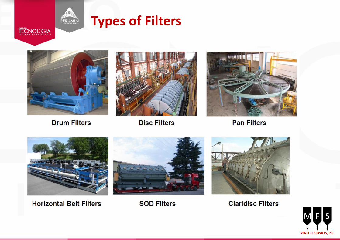
Types of Filters

Pumping Paste Backfill
Verkerk was the first to note the conundrum of aggregate paste systems In laminar flow conditions the YS increases as the coarse fraction increases In the non-Newtonian range pressure losses go down as the coarse fraction in
increased Many of the early paste systems contained aggregates – e.g. Bad Grund, Lucky Friday,
Boliden Garpenberg In 1992 it was not possible to pump paste – Landriault In 1994 it was possible to pump paste 1 km - Brackebusch In 1998 it was possible to pump paste 3 km – Brackebush Today several mines pump paste 3-4 km Nowadays the practical limit is taken to be about 2 km due to economics Lucky Friday and many early paste plants learned hard lessons about pumping paste –
freefalls, abrupt bends, air entry in dropholes, design of couplers, hangers, pipe supports

Pumping Paste Backfill
1970 – first truck mounted Putzmeister concrete pump with M16 boom and 100mm delivery line
Putzmeister Elephant concrete pump at Bad Grund in 1980. These pumps could deliver fill horizontally 2,000m

Modern Paste Pumps

The Early Adopters of Paste Backfill
Cannington – 1998 First paste plant built by Pastec
Stillwater – 1997 First DCT licensed under the Alcan agreement

The Early Adopters of Paste Backfill
Ewarton Bauxite - Jamaica First bauxite paste plant built by Alcan
Photo courtesy of FLSmidth
Pajingo Gold – Australia - 2000 14m diameter with bolted tank design
Photo courtesy of Outotec
150 paste plants built – at least a dozen plants here in Peru Adding 5 new plants per year

Paste Control Technology has Evolved
Then – Garson plant - 1994 Now – modern paste plant control room

Paste Rheology then and Now
A modern minesite paste laboratory versus those that like the old way ..

Paste Backfill Gains Global Acceptance
Symposia Paste Related Papers
1973 – Mount Isa 0
1978 - Sudbury 0
1983 - Montreal 0
1989 - Sweden 2
1993 - South Africa 2
1998 - Brisbane 12
2001 - Seattle 11
2004 - Bejiing 11
2007 - Montreal 13
2011 - Cape Town 10
2013 - Perth 22
Minefill Symposia Paste Symposia
Symposia Backfill Related Papers
2014 – Vancouver 4
2013 - Brazil 6
2012 – South Africa 1
2011 - Perth 7
2010 - Toronto 12
2009 - Chile 1
2008 - Botswana 1
2007 - Perth 4
2006 - Ireland 8
2005 - Santiago 4

Backfill Roles
Void filler for disposal of mining wastes – tailings or waste rock Provides a working floor for overhand cut and fill mining Increases resource extraction through the recovery of pillars Increases safety in unstable or rock burst prone ground – high stresses Decreases subsidence from mining due to filling of voids
Specific to Peru
Allows for the safe disposal of mine wastes in steep terrain Reduces/mitigates impact of acid drainage Allow underground disposal of sulfide tailings prone to acidity on
surface
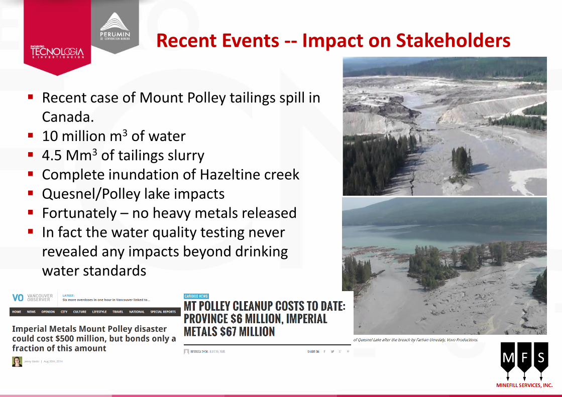
Recent Events -- Impact on Stakeholders
Recent case of Mount Polley tailings spill in Canada.
10 million m3 of water 4.5 Mm3 of tailings slurry Complete inundation of Hazeltine creek Quesnel/Polley lake impacts Fortunately – no heavy metals released In fact the water quality testing never
revealed any impacts beyond drinking water standards

The Result - Increased Stakeholder Demands
Who are the stakeholders: Include government regulators The general public NGO’s and Activist groups Financial community that funds mining
An unintended consequence of the Mount Polley breach was the quick reaction by Alaskan communities, first nations groups, and activist groups who united to condemn mining.
First nations want a say in approval of project designs and project permits, as does Alaska.
The failure of a “well engineered” facility run by a reputable company in a first world jurisdiction with regulatory oversight has unsettled many and provided ammunition for activist and NGO fights against mining projects.

The New Reality
The Mount Polley Investigative Report has recommended: The elimination of water from tailings impoundments Adoption of “Best Available Technologies”
The outcome is a strong push towards: “dry stack” surface disposal of filtered tailings Maximizing the use of mine backfills which use tailings
The Future Stakeholders will push for zero impacts due to mining
Conservation of water Minimal surface disturbance Minimal long term monitoring or remediation after closure
Regulators will push for the elimination of wet tailings disposal Mining companies need to adopt technologies that maximize use of tailings based backfill
systems such as paste backfill Surface disposal will focus on paste thickened tailings or dry stacking
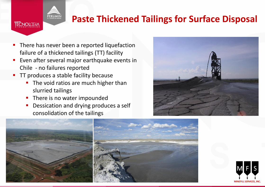
Paste Thickened Tailings for Surface Disposal
There has never been a reported liquefaction failure of a thickened tailings (TT) facility
Even after several major earthquake events in Chile - no failures reported
TT produces a stable facility because The void ratios are much higher than
slurried tailings There is no water impounded Dessication and drying produces a self
consolidation of the tailings

Beach Angles in Thickened Tailings
Extremely difficult to predict Laboratory models eg flume tests, have proven to be grossly inadequate Numerical models have likewise proven to be extremely complex Bottom line – most beach slopes average about 0.5% to 2% over the length of beach Can get steeper near discharge – up to 8% locally but only over very short distances
Be
ach
An
gle

Dry Stack for Surface Disposal
MILPO – Cerro Lindo

Best Practices for Mine Fills
Farming of dried tailings from existing or closed tailings impoundments is very popular in Australia Saves on dewatering tailings – capital and operating
costs Smaller plant that can be mobile Saves on reclamation of old tailings sites

Best Practices for Mine Fills - Barricades
Barricades serve many roles: CRF – confinement of the rockfill – no risk of flow HF – containment of water and fine solids – LQ risk CPF – containment of the un-cured paste – LQ risk
Loading on a barricade is time dependent, material dependent, and barricade design dependent
Selection of the ideal barricade is dependent on the short and long term loading: Short term – HF or CPF as a fluid Long term – drained HF or cured CPF
Barricades are generally much stronger if arched – up to 3x capacity of a flat fence

Best Practices for Mine Fills - Barricades
Waste rock with timber cap
Cable Fence with Welded Wire Mesh
Cable Fence with Welded Wire Mesh
Timber fence
Shotcrete

Best Practices for Mine Fills - Barricades
Liquefaction of paste poses a real hazard. There have been over a dozen reported failures. Risk is highest 12-24 hrs after pouring
There have been a number of bulkhead failures due to liquefaction of paste. One incident due to over-pressuring due to a plugged vent line Several incidents due to massive in-stope back and wall failures Several incidents due to excessive filling rates, or not allowing an initial rest period after
covering the barricade Several incidents have been traced back to excess water in the paste during pouring due
to groundwater inflow or dumping flush water into the paste. Paste mixes at 0.5% are clearly liquefiable, whereas mixes at 1% are considered marginal.
Mixes at > 2% are liquefaction resistant The industry standard of >100kPa paste strength appears to be conservative.

HF Best Practices - Barricades
Barricade loads can be controlled with proper controls on fill placement – e.g controlled pouring rates (controlled rate of rise), rest periods, and visual monitoring by CCTV.
For HF the initial pour should not exceed 2m above the brow, then allow rest period for fill to fully drain
Critical with HF to allow rest periods during pours dependent on size of stope. Do not allow a large decant pool to develop.
HF barricade design may need to withstand full hydrostatic pressure to height of stope.

Paste Fill Best Practices - Barricades
Again barricade loading is dependent on a controlled fill schedule In paste the horizontal loading generally is < 200 kPa Controlled by an initial plug pour to 2m above brow of drawpoint and
24 to 72 hr rest period to allow paste to cure. Paste plug is designed for full vertical load of overlying paste Barricade should never be placed right at brow – setback at least 1m Establish a non-entry zone around barricades during pouring

Come and see us in Denver in 2017

GRACIAS.