European Technical ETA -11/0409 Assessment of 29 November …
19
Z72296.16 8.06.01-85/16 European Technical Assessment ETA-11/0409 of 29 November 2016 English translation prepared by DIBt - Original version in German language General Part Technical Assessment Body issuing the European Technical Assessment: Deutsches Institut für Bautechnik Trade name of the construction product Eternit undercut anchor Tergo for Eternit facade panels EQUITONE Product family to which the construction product belongs Fastener for the rear fixing of facade panels made of fibre-cement according to EN 12467:2012 Manufacturer Eternit GmbH Im Breitspiel 20 69126 Heidelberg DEUTSCHLAND Manufacturing plant Eternit Werk This European Technical Assessment contains 19 pages including 3 annexes which form an integral part of this assessment This European Technical Assessment is issued in accordance with Regulation (EU) No 305/2011, on the basis of European Assessment Document (EAD) 330030-00-0601 electronic copy of the eta by dibt: eta-11/0409
Transcript of European Technical ETA -11/0409 Assessment of 29 November …

Z72296.16 8.06.01-85/16
European Technical
Assessment
ETA-11/0409
of 29 November 2016 English translation prepared by DIBt - Original version in German language General Part
Technical Assessment Body issuing the European Technical Assessment:
Deutsches Institut für Bautechnik
Trade name of the construction product Eternit undercut anchor Tergo for Eternit facade panels EQUITONE
Product family to which the construction product belongs
Fastener for the rear fixing of facade panels made of fibre-cement according to EN 12467:2012
Manufacturer Eternit GmbH Im Breitspiel 20 69126 Heidelberg DEUTSCHLAND
Manufacturing plant Eternit Werk
This European Technical Assessment contains
19 pages including 3 annexes which form an integral part of this assessment
This European Technical Assessment is issued in accordance with Regulation (EU) No 305/2011, on the basis of
European Assessment Document (EAD) 330030-00-0601
elec
troni
c co
py o
f the
eta
by
dibt
: et
a-11
/040
9
European Technical Assessment
ETA-11/0409
English translation prepared by DIBt
Page 2 of 19 | 29 November 2016
Z72296.16 8.06.01-85/16
The European Technical Assessment is issued by the Technical Assessment Body in its official language. Translations of this European Technical Assessment in other languages shall fully correspond to the original issued document and shall be identified as such.
Communication of this European Technical Assessment, including transmission by electronic means, shall be in full. However, partial reproduction may only be made with the written consent of the issuing Technical Assessment Body. Any partial reproduction shall be identified as such.
This European Technical Assessment may be withdrawn by the issuing Technical Assessment Body, in particular pursuant to information by the Commission in accordance with Article 25(3) of Regulation (EU) No 305/2011.
elec
troni
c co
py o
f the
eta
by
dibt
: et
a-11
/040
9
European Technical Assessment
ETA-11/0409
English translation prepared by DIBt
Page 3 of 19 | 29 November 2016
Z72296.16 8.06.01-85/16
Specific Part
1 Technical description of the product
The Eternit undercut anchor Tergo for air cured Eternit façade panels EQUITONE ([materia], [natura], [natura] PRO, [pictura] and [textura]) is an anchor made of a crosswise slotted anchor sleeve with internal thread and a rectangular sheet metal at the top, a related flat head screw and a washer. The anchor sleeve, flat head screw and washer are made of stainless steel.
The anchor is put into an undercut drill hole, locked against rotation by setting to the fixing member (single agraffe, double agraffe, long-span agraffe or panel load-bearing profile) and placed form-fitted and anchored way-controlled by pulling the screw.
The product description is given in Annex A.
2 Specification of the intended use in accordance with the applicable European Assessment Document
The performances given in Section 3 are only valid if the anchor is used in compliance with the specifications and conditions given in Annex B.
The verifications and assessment methods on which this European Technical Assessment is based lead to the assumption of a working life of the anchors of at least 50 years. The indications given on the working life cannot be interpreted as a guarantee given by the producer, but are to be regarded only as a means for choosing the right products in relation to the expected economically reasonable working life of the works.
3 Performance of the product and references to the methods used for its assessment
3.1 Mechanical resistance and stability (BWR 1)
Essential characteristic Performance
Characteristic resistance for tension and shear loads See Annex C 1
Anchor distances and dimensions of members See Annex C 1
3.2 Safety in case of fire (BWR 2)
Essential characteristic Performance
Reaction to fire Class A 1
Resistance to fire No performance assessed
4 Assessment and verification of constancy of performance (AVCP) system applied, with reference to its legal base
In accordance with EAD No. 330030-00-0601 the applicable European legal act is: [97/161/EG].
The system to be applied is: 2+
elec
troni
c co
py o
f the
eta
by
dibt
: et
a-11
/040
9

European Technical Assessment
ETA-11/0409
English translation prepared by DIBt
Page 4 of 19 | 29 November 2016
Z72296.16 8.06.01-85/16
5 Technical details necessary for the implementation of the AVCP system, as provided for in the applicable European Assessment Document
Technical details necessary for the implementation of the AVCP system are laid down in the control plan deposited with Deutsches Institut für Bautechnik.
Issued in Berlin on 29 November 2016 by Deutsches Institut für Bautechnik
Andreas Kummerow beglaubigt:
p. p. Head of Department Aksünger
elec
troni
c co
py o
f the
eta
by
dibt
: et
a-11
/040
9

Page 5 of European Technical Assessment ETA-11/0409 of 29 November 2016
English translation prepared by DIBt
Z79091.16 8.06.01-85/16
Eternit undercut anchor Tergo for Eternit facade panels EQUITONE
Product description Installed anchor
Annex A 1
Installed Eternit Tergo undercut anchor Example of a facade panel with fixing member – single agraffe
Example of a facade panel with fixing member – panel load bearing profile
Eternit facade panel EQUITONE
agraffe flat head screw with rolled plate
anchor sleeve
Eternit facade panel EQUITONE
agraffe
flat head screw with rolled plate anchor sleeve
elec
troni
c co
py o
f the
eta
by
dibt
: et
a-11
/040
9

Page 6 of European Technical Assessment ETA-11/0409 of 29 November 2016
English translation prepared by DIBt
Z79091.16 8.06.01-85/16
Eternit undercut anchor Tergo for Eternit facade panels EQUITONE
Product description Fixing example
Annex A 2
Fixing example: Façade construction with fixing member – single agraffe
vertikal support profil adjusting screw (horizontal skid)
single agraffe horizontal fix point horizontal support profil (profile for single agraffes)
elec
troni
c co
py o
f the
eta
by
dibt
: et
a-11
/040
9

Page 7 of European Technical Assessment ETA-11/0409 of 29 November 2016
English translation prepared by DIBt
Z79091.16 8.06.01-85/16
Eternit undercut anchor Tergo for Eternit facade panels EQUITONE
Product description System components
Annex A 3
System components
anchor sleeve flat head screw with rolled plate
supplied anchor sleeve
(dimensions in mm, without scale)
Table A1: Material
anchor sleeve stainless steel 1.4404 according EN 10088:2014
flat head screw with rolled plate stainless steel 1.4578 or 1.4401 or 1.4404 according EN 10088:2014
Identifiying mark:
elec
troni
c co
py o
f the
eta
by
dibt
: et
a-11
/040
9

Page 8 of European Technical Assessment ETA-11/0409 of 29 November 2016
English translation prepared by DIBt
Z79091.16 8.06.01-85/16
Eternit undercut anchor Tergo for Eternit facade panels EQUITONE
Intended use Specifications
Annex B 1
Specifications of intended use Anchorages subject to:
Static und quasi-static loads
Base materials:
The Eternit facade panels EQUITONE shall correspond to EN 12467:2012.
Use conditions (Umweltbedingungen):
Structures subject to dry internal conditions,
Structures subject to external atmospheric exposure (including industrial and marine environment) and to permanently damp internal condition, if no particular aggressive conditions exist.
Note: Particular aggressive conditions are e.g. permanent, alternating immersion in seawater or the splash zone of seawater, chloride atmosphere of indoor swimming pools or atmosphere with extreme chemical pollution (e.g. in desulphurization plants or road tunnels where de-icing materials are used).
Design:
The design of the façade panels and their fixing is carried out according to the conditions given in Annex B 3 bis B 5.
Installation:
The drillings are done at the factory or on site under workshop conditions; when making the drillings on site the execution is supervised by the responsible project supervisor or a skilled representative of the project supervisor.
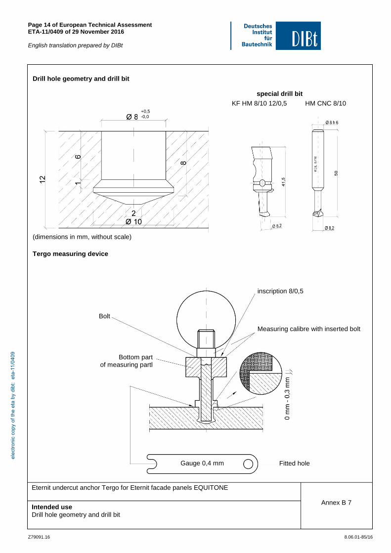
Making of the undercut drilling is done with the drill bit according to Annex B 7 and a special CNC drilling device according to Annex B 6 and in accordance with the information deposited with Deutsches Institut für Bautechnik.
Cleaning of the drill hole.
In case of aborted hole: new drilling at a minimum distance away of twice the depth of the aborted hole.
The geometry of the drill hole is checked on 1 % of all drillings. The following dimensions shall be checked and documented according to manufacturer's information and testing instructions by means of a measuring device according to Annex B 7:
Volume of the undercut drill hole.
Depth position of the undercut; the distance between the lower edge of the meausuringdevice and the faced panel is between 0,0 and 0,3 mm (see Annex B 7).
If the tolerances given in Annex A 2, Table A1 are exceeded, the geometry of the drill hole shall be checked on 25% of the drillings performed. No further drill hole may exceed the tolerances otherwise all the drill holes shall be controlled. Drilling holes falling below or exceeding the tolerances shall be rejected.
Note: Checking the geometry of the drill hole on 1 % of all drillings means that on one of the 25 panels (this corresponds to 100 drillings in façade panels with four anchors) one drilling shall be checked. If the tolerances given in Annex A 2, Table A1 are exceeded the extent of the control shall be increase to 25 % of the drillings, i.e. one drilling each shall be checked on all the 25 panels.
During transport and storage on site the façade panels are protected from damages; the façade panels are not be hung up jerkily (if need be lifters shall be used for hanging up the façade panels); façade panels and reveal panels respectively with incipient cracks are not be installed.
The façade are installed by skilled specialists and the laying instructions of the manufacturer shall be paid attention to.
elec
troni
c co
py o
f the
eta
by
dibt
: et
a-11
/040
9

Page 9 of European Technical Assessment ETA-11/0409 of 29 November 2016
English translation prepared by DIBt
Z79091.16 8.06.01-85/16
Eternit undercut anchor Tergo for Eternit facade panels EQUITONE
Intended use Specifications
Annex B 2
The anchor is put into an undercut drill hole, locked against rotation by setting to the fixing member and placed form-fitted and anchored way-controlled by pulling the screw. Fixing the screw is achieved with a torque moment (2,5 Nm ≤ Tinst ≤ 4,0 Nm) using a calibrated torque.
Installation of the anchor in rectangular holes (sliding points) needs additional spring washers between anchor sleeve and washer.
The façade panels are arranged in a "reclined" or "upright" position, they also may be fixed at façade soffits.
elec
troni
c co
py o
f the
eta
by
dibt
: et
a-11
/040
9

Page 10 of European Technical Assessment ETA-11/0409 of 29 November 2016
English translation prepared by DIBt
Z79091.16 8.06.01-85/16
Eternit undercut anchor Tergo for Eternit facade panels EQUITONE
Intended use Design method
Annex B 3
Design method
General:
The design values of the actions shall be calculated on basis of EN 1990 in consideration of the existing loads. The combinations of actions shall be equal to EN 1990. The actions shall be specified according to EN 1991-1-1 to EN 1991-1-7. Corresponding national regulations shall be taken into consideration. The unfavourable combination is decisive. Where necessary for the design of the anchor and the façade panel several combinations shall be analysed separately.
The typical fundamental combination for façade panels considers actions from dead load FEk.G (permanent action) and wind FEk.w (leading variable action).
According to EN 1990 the following fundamental combination depending on the load direction results for a vertical façade panel:
Fundamental combination for loads parallel to the panel: FEd = FEk,G · γG
Fundamental combination for loads perpendicular to the panel: FEd = FEk,w · γQ
mit γG = 1,35; γQ = 1,50
For hanging panels (over head mounting) or reveals respectively the load direction shall be taken into consideration
and the combinations of actions shall be based on EN 1990.
The calculation shall be carried out in a linear elastic manner. The stiffness of the substructure shall be considered for the respective case of application.
Each façade panel is fixed with at least four anchors in a rectangular arrangement via single agraffes on the substructure (for small panels or small fitted pieces, differential or fill- in pieces the number and position of the anchors shall be chosen constructively).
The substructure is constructed such that the façade panels are fixed technically strain-free via skids (loose bearings) and one fixed point (fixed bearing) - the fixed point may be placed at the panel edge or in the panel field.
Two fixing points of the façade panel are designed such that they are able to carry the dead load of the façade panel.
When using agraffes on horizontal load-bearing profiles the fixing points of a façade panel situated horizontally at the same height are fastened in each case to the same load-bearing profile.
The thickness of the fixing member (agraffe or panel load-bearing profile) shall be at least 2,0mm and must not exceed 3,0 mm.
At the agraffes or panel load-bearing profiles shall be arranged one square hole with 10.2 mm x 10.2 mm (fixed point). Agraffes with two anchors shall provide one rectangular hole with the dimension 10.2 mm x 14.2 mm (sliding point). At the panel load-bearing profile shall be arranged further holes with the dimension 10.2 mm x 20 mm to ensure a strain-free bearing of the façade panels at the panel load-bearing profile. Annex B 5 shows fixed points and loose points.
Joint construction between the façade panels is done by a joint filler or are kept open; open joints between fibre-cement sheetsmust not be greater than 12mm; it is ensured that additional stresses (e.g. by temperature) do not lead to important additional loadings.
Verifiable calculation notes and drawings shall be prepared taking account of the loads to be anchored, the nature and strength of the base materials and the dimensions of the anchorage members as well as of the relevant tolerances. The position of the anchor is indicated on the design drawings.
The façade panels, their fixings as well as the substructure including its connection to wall brackets and their connection to the construction works are designed for the respective case of application under the responsibility of an engineer skilled in the field of façade construction.
elec
troni
c co
py o
f the
eta
by
dibt
: et
a-11
/040
9

Page 11 of European Technical Assessment ETA-11/0409 of 29 November 2016
English translation prepared by DIBt
Z79091.16 8.06.01-85/16
Eternit undercut anchor Tergo for Eternit facade panels EQUITONE
Intended use Design method
Annex B 4
Guideline for structural calculation by means of FE – method
For structural calculation by means of the Finite-Element-Method the façade panels are tobe idealized with their effective dimensions (size and thickness) as panel elements. The system chosen shall have the capacity to sufficiently precise represent the tension and the deformation state as well as the support reactions of the façade panels. The relevant bending stress for the verification is obtained at the fixing range in a distance of 60 mm from the anchor axis. The mesh size at fixing range shall be at least 9 mm and shall not exceed 30 mm.
Verification of the anchor loads
For flush fixed anchors and for installation of horizontal load-bearing profiles permanent loads due to torsion of the profile shall be considered in addition to actions from dead loads and wind in direction of the anchor axes. The load due to torsion can be neglected, when there is no horizontal distance between anchor and vertical load-bearing profile.
Simplified, it can be determined as follows:
NV,Ek = VEk • e/z
NEd = NEk,w • ɣQ + NV,Ek • ɣG
VEk = characteristic shear load due to dead load of the façade panel
M = shear centre of horizontal support profile
z = spacing of forces
e = distance between shear load and shear centre M [mm]
elec
troni
c co
py o
f the
eta
by
dibt
: et
a-11
/040
9

Page 12 of European Technical Assessment ETA-11/0409 of 29 November 2016
English translation prepared by DIBt
Z79091.16 8.06.01-85/16
Eternit undercut anchor Tergo for Eternit facade panels EQUITONE
Intended use Design method
Annex B 5
For the determined anchor forces it shall be verified, that the following equation are met:
Equation 1: 1N
N
Rd
Ed
Equation 2: 1V
V
Rd
Ed
Additional equation 3, if tension load and shear load exist in same time.
Equation 3: 1V
V
N
N5,1
Rd
Ed
5,1
Rd
Ed
with:
NEd = design value of the tensile force acting on the anchor
VEd = design value of the shear force acting on the anchor
NRd = design value of the tensile load-bearing capacity of the anchor: NRd = NRk / M (with NRk und M according to Annex C 1)
VRd = design value of the shear load-bearing capacity of the anchor: VRd = VRk / M (with VRk und M according to Annex C 1)
Verification of the bending stress:
The bending stress in the façade panels is to be verified, that the following equation is observed.
Equation 4: 1Rd
Ed
with:
Ed = design value of the bending stress of the façade panel
Rd = design value of the bending stress resistance of the façade panel: Rd = Rk / M (with Rk and M according to Anhang C 1)
elec
troni
c co
py o
f the
eta
by
dibt
: et
a-11
/040
9
Page 13 of European Technical Assessment ETA-11/0409 of 29 November 2016
English translation prepared by DIBt
Z79091.16 8.06.01-85/16
Eternit undercut anchor Tergo for Eternit facade panels EQUITONE
Intended use Requirements to the Eternit – façade panels
Annex B 6
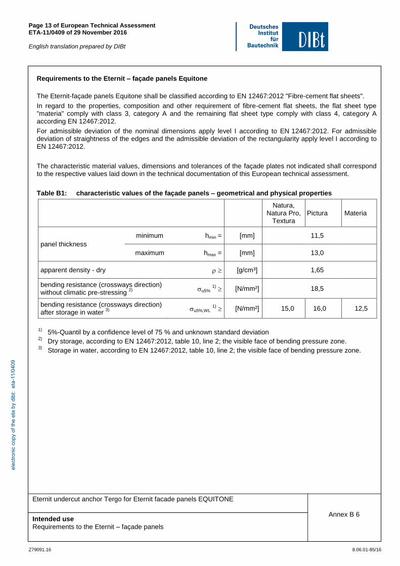
Requirements to the Eternit – façade panels Equitone
The Eternit-façade panels Equitone shall be classified according to EN 12467:2012 "Fibre-cement flat sheets".
In regard to the properties, composition and other requirement of fibre-cement flat sheets, the flat sheet type "materia" comply with class 3, category A and the remaining flat sheet type comply with class 4, category A according EN 12467:2012.
For admissible deviation of the nominal dimensions apply level I according to EN 12467:2012. For admissible deviation of straightness of the edges and the admissible deviation of the rectangularity apply level I according to EN 12467:2012.
The characteristic material values, dimensions and tolerances of the façade plates not indicated shall correspond to the respective values laid down in the technical documentation of this European technical assessment.
Table B1: characteristic values of the façade panels – geometrical and physical properties
Natura,
Natura Pro, Textura
Pictura Materia
panel thickness
minimum hmin = [mm] 11,5
maximum hmax = [mm] 13,0
apparent density - dry [g/cm³] 1,65
bending resistance (crossways direction) without climatic pre-stressing
2)
u5% 1)
[N/mm²] 18,5
bending resistance (crossways direction) after storage in water
3)
u5%,WL 1)
[N/mm²] 15,0 16,0 12,5
1)
5%-Quantil by a confidence level of 75 % and unknown standard deviation 2)
Dry storage, according to EN 12467:2012, table 10, line 2; the visible face of bending pressure zone. 3)
Storage in water, according to EN 12467:2012, table 10, line 2; the visible face of bending pressure zone.
elec
troni
c co
py o
f the
eta
by
dibt
: et
a-11
/040
9
Page 14 of European Technical Assessment ETA-11/0409 of 29 November 2016
English translation prepared by DIBt
Z79091.16 8.06.01-85/16
Eternit undercut anchor Tergo for Eternit facade panels EQUITONE
Intended use Drill hole geometry and drill bit
Annex B 7
Drill hole geometry and drill bit special drill bit
KF HM 8/10 12/0,5 HM CNC 8/10
(dimensions in mm, without scale)
Tergo measuring device
inscription 8/0,5 Measuring calibre with inserted bolt
Agraffe Horizontales Tragprofil (Agraffenprofil)
Bolt
Agraffe Horizontales Tragprofil (Agraffenprofil)
Bottom part of measuring partl
Agraffe
Gauge 0,4 mm
Fitted hole
Agraffe
+0,5 -0,0
elec
troni
c co
py o
f the
eta
by
dibt
: et
a-11
/040
9
Page 15 of European Technical Assessment ETA-11/0409 of 29 November 2016
English translation prepared by DIBt
Z79091.16 8.06.01-85/16
Eternit undercut anchor Tergo for Eternit facade panels EQUITONE
Intended use Example of arrangement of fixing points
Annex B 8
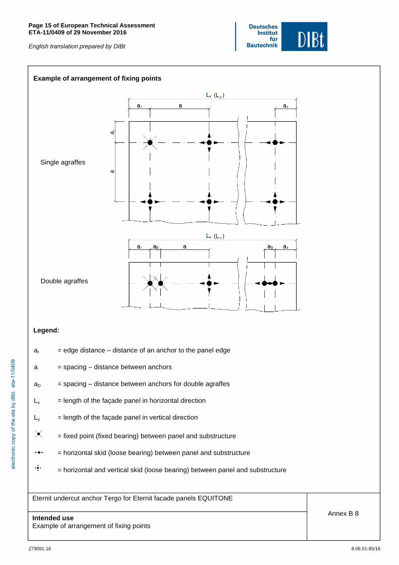
Example of arrangement of fixing points
Legend:
ar = edge distance – distance of an anchor to the panel edge
a = spacing – distance between anchors
aD = spacing – distance between anchors for double agraffes
Lx = length of the façade panel in horizontal direction
Ly = length of the façade panel in vertical direction
= fixed point (fixed bearing) between panel and substructure
= horizontal skid (loose bearing) between panel and substructure
= horizontal and vertical skid (loose bearing) between panel and substructure
Single agraffes
Double agraffes
elec
troni
c co
py o
f the
eta
by
dibt
: et
a-11
/040
9

Page 16 of European Technical Assessment ETA-11/0409 of 29 November 2016
English translation prepared by DIBt
Z79091.16 8.06.01-85/16
Eternit undercut anchor Tergo for Eternit facade panels EQUITONE
Intended use Example for fixed point and loose bearing
Annex B 9
Example for fixed point and loose bearing
1. 2. 3.
1. – fixed point substructure with fixed point between façade panel and substructure
2. - fixed point substructure with horizontal loose point between façade panel and substructure 3. – loose point substructure with horizontal and vertical loose point between façade panel and substructure
Geometry of clearance hole at fixing member for fixed point (fixed bearing) and skid (loose bearing)
(dimensions in mm, without scale) Note:
Installation of the anchor in rectangular holes of panel load-bearing profiles needs additional spring washers
M6 DIN 7980 A2 between anchor sleeve and washer.
squared hole 10,2 mm x 10,2 mm as fixed bearing
rectangular hole 10,2 mm x 14,2 mm (up to 20 mm possible) as loose bearing
elec
troni
c co
py o
f the
eta
by
dibt
: et
a-11
/040
9

Page 17 of European Technical Assessment ETA-11/0409 of 29 November 2016
English translation prepared by DIBt
Z79091.16 8.06.01-85/16
Eternit undercut anchor Tergo for Eternit facade panels EQUITONE
Intended use Installation instructions
Annex B 10
Installation instruction 1. Drilling the undercut hole a) cylindrical drilling b) undercutting and cleaning c) finished undercut hole 2. Checking the undercut hole
0,4
Agraffe
elec
troni
c co
py o
f the
eta
by
dibt
: et
a-11
/040
9
Page 18 of European Technical Assessment ETA-11/0409 of 29 November 2016
English translation prepared by DIBt
Z79091.16 8.06.01-85/16
Eternit undercut anchor Tergo for Eternit facade panels EQUITONE
Intended use Installation instructions
Annex B 11
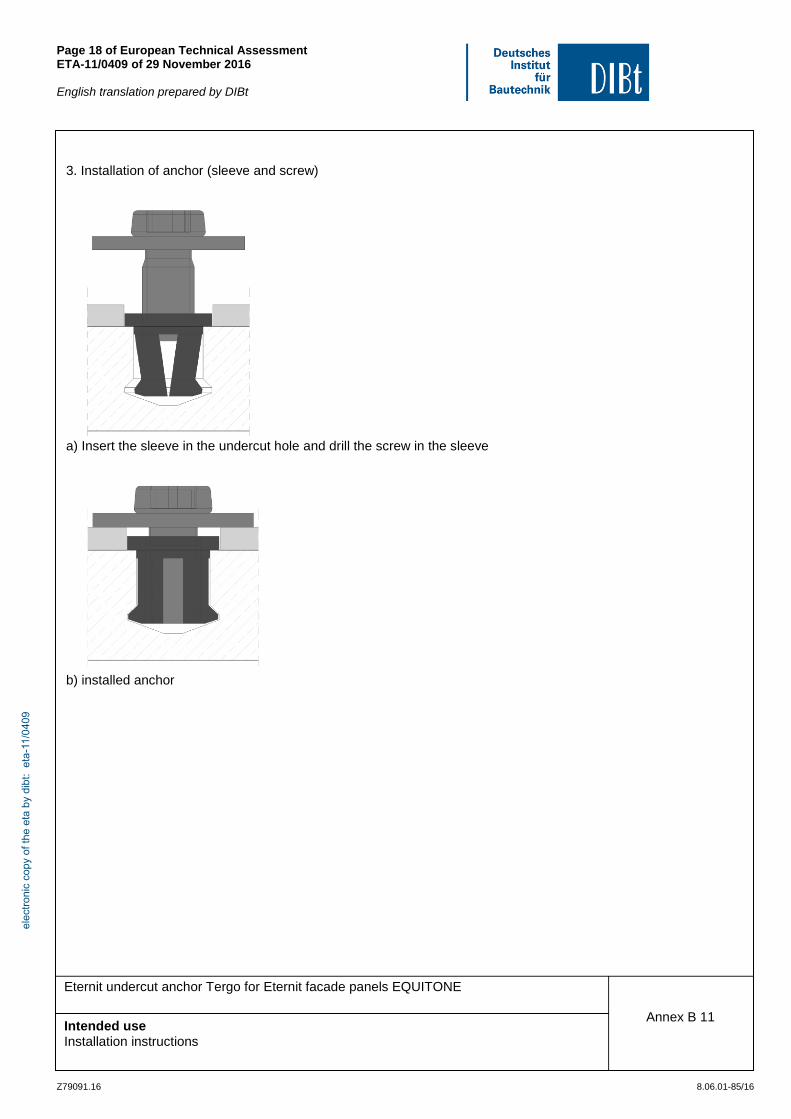
3. Installation of anchor (sleeve and screw)
a) Insert the sleeve in the undercut hole and drill the screw in the sleeve
b) installed anchor
elec
troni
c co
py o
f the
eta
by
dibt
: et
a-11
/040
9

Page 19 of European Technical Assessment ETA-11/0409 of 29 November 2016
English translation prepared by DIBt
Z79091.16 8.06.01-85/16
Eternit undercut anchor Tergo for Eternit facade panels EQUITONE
Performances Characteristic values for the design of the anchor
Annex C 1
Tabelle C1: Characteristic values for the design of the anchor
Pa
ram
ete
rs o
f fa
çad
e p
an
el
Type of facade panel Natrua
Natura PRO Textura
Pictura Materia
max. panel size Lx x Ly
[mm] x [mm] 3100 x 1500 Ly x Lx
Characteristic bending resistance
Rk [N/mm²] 18,5
Partial safety factor 1)
M = [-] 2,62 2,94 2,74
modulus of elasticity Emean = [N/mm²] 12000
nominal panel thickness
hnom = [mm] 12
Poisson's ratio
= [-] 0,25
Dead load gk = [kN/m²] 0,26
Coefficient of thermal expansion
T = [10-6
K-1
] 10
Para
mete
rs o
f anch
or
anchorage depth hs = [mm] 8
tension load 2)
characteristic resistance
NRk = [kN] 1,1 1,2 1,0
edge distance 3)
ar ≥ [mm] 50
0,1 x a
spacing a ≥ [mm] 100 ≤ a ≤ 750
a ≤ 400 4)
shear load 2)
characteristic resistance
VRk = [kN] 2,2 2,4 1,7
edge distance ar ≥ [mm] 100
spacing a ≥ [mm] 200
Double agraffe spacing aD ≥ [mm] 45
Partial safety factor 1)
M = [-] 1,8
1) In absence of other national regulations
2) In case of coincident stress of an anchor due to tension and shear load the equation 3 in annex B5 shall be
observed 3)
The higher value is decisive. For small fitted pieces, differential and fill-in pieces the edge distance and spacing shall be chosen constructively
4) For use of the façade panels as soffits
elec
troni
c co
py o
f the
eta
by
dibt
: et
a-11
/040
9