8.6.2000 EN Official Journal of the European Communities L ...

Diese Zulassung umfasst
This Approval contains
22 Seiten einschlieszliglich 11 Anhaumlnge 22 pages including 11 annexes
E u r o p auml i s c h e O r g a n i s a t i o n f uuml r T e c h n i s c h e Z u l a s s u n g e n
E u r o p e a n O r g a n i s a t i o n f o r T e c h n i c a l A p p r o v a l s
Z7592612 80604-22811
English translation prepared by DIBt - Original version in German language
Handelsbezeichnung Trade name
Tecfi RahmenMulti-Funktionsduumlbel VS-Handyplug reg
Tecfi framemulti-purpose anchor VS-Handyplug (R)
Zulassungsinhaber
Holder of approval Tecfi SpA Strada Statale Appia Km 193 81050 PASTORANO (CE) ITALIEN
Zulassungsgegenstand und Verwendungszweck
Kunststoffduumlbel als Mehrfachbefestigung von nichttragenden Systemen zur Verankerung im Beton und Mauerwerk
Generic type and use of construction product
Plastic anchor for multiple use in concrete and masonry for non-structural applications
Geltungsdauer
Validity vom from
21 March 2013
bis to
21 March 2018
Herstellwerk
Manufacturing plant Tecfi SpA Strada Statale Appia Km 193 81050 PASTORANO (CE) ITALIEN
European technical approval ETA-130135
European technical approval ETA-130135 English translation prepared by DIBt
Page 2 of 22 | 21 March 2013
Z7592612 80604-22811
I LEGAL BASES AND GENERAL CONDITIONS
1 This European technical approval is issued by Deutsches Institut fuumlr Bautechnik in accordance with
- Council Directive 89106EEC of 21 December 1988 on the approximation of laws regulations and administrative provisions of Member States relating to construction products1 modified by Council Directive 9368EEC2 and Regulation (EC) Ndeg 18822003 of the European Parliament and of the Council3
- Gesetz uumlber das In-Verkehr-Bringen von und den freien Warenverkehr mit Bauprodukten zur Umsetzung der Richtlinie 89106EWG des Rates vom 21 Dezember 1988 zur Angleichung der Rechts- und Verwaltungsvorschriften der Mitgliedstaaten uumlber Bauprodukte und anderer Rechtsakte der Europaumlischen Gemeinschaften (Bauproduktengesetz - BauPG) vom 28 April 19984 as amended by Article 2 of the law of 8 November 20115
- Common Procedural Rules for Requesting Preparing and the Granting of European technical approvals set out in the Annex to Commission Decision 9423EC6
- Guideline for European technical approval of Plastic Anchors for Multiple Use in Concrete and Masonry for Non-structural Applications - Part 1 General ETAG 020-01
2 Deutsches Institut fuumlr Bautechnik is authorized to check whether the provisions of this European technical approval are met Checking may take place in the manufacturing plant Nevertheless the responsibility for the conformity of the products to the European technical approval and for their fitness for the intended use remains with the holder of the European technical approval
3 This European technical approval is not to be transferred to manufacturers or agents of manufacturers other than those indicated on page 1 or manufacturing plants other than those indicated on page 1 of this European technical approval
4 This European technical approval may be withdrawn by Deutsches Institut fuumlr Bautechnik in particular pursuant to information by the Commission according to Article 5(1) of Council Directive 89106EEC
5 Reproduction of this European technical approval including transmission by electronic means shall be in full However partial reproduction can be made with the written consent of Deutsches Institut fuumlr Bautechnik In this case partial reproduction has to be designated as such Texts and drawings of advertising brochures shall not contradict or misuse the European technical approval
6 The European technical approval is issued by the approval body in its official language This version corresponds fully to the version circulated within EOTA Translations into other languages have to be designated as such
1 Official Journal of the European Communities L 40 11 February 1989 p 12
2 Official Journal of the European Communities L 220 30 August 1993 p 1
3 Official Journal of the European Union L 284 31 October 2003 p 25
4 Bundesgesetzblatt Teil I 1998 p 812
5 Bundesgesetzblatt Teil I 2011 p 2178
6 Official Journal of the European Communities L 17 20 January 1994 p 34
European technical approval ETA-130135 English translation prepared by DIBt
Page 3 of 22 | 21 March 2013
Z7592612 80604-22811
II SPECIFIC CONDITIONS OF THE EUROPEAN TECHNICAL APPROVAL
1 Definition of product and intended use
11 Definition of the construction product
The frame anchor VS-Handyplug is a plastic anchor consisting of a plastic sleeve made of polyamide and an accompanying specific screw of galvanised steel or of stainless steel
The plastic sleeve is expanded by screwing in the specific screw which presses the sleeve against the wall of the drilled hole
The installed anchor is shown in Annex 1
12 Intended use
The anchor is intended to be used for anchorages for which requirements for safety in use in the sense of the Essential Requirement 4 of Council Directive 89106EEC shall be fulfilled and failure of the fixture represents an immediate risk to human life
The anchor is to be used only for multiple fixing for non-structural applications
The base material may consist of use category a b and c as given in the following Table
Use category
Anchor type
Remarks
a Tecfi VS-Handyplug
bull Concrete with strength class C1215 at minimum and C5060 at maximum according to EN 206-12000-12
bull Cracked and non-cracked concrete bull The anchor may also be used with requirements related to
resistance to fire according 422
b Tecfi VS-Handyplug
bull Masonry walls according to Annex 6 bull Mortar strength class ge M 25 according to EN 998-22003
c Tecfi VS-Handyplug
bull Masonry walls according to Annex 8 bull Mortar strength class ge M 25 according to EN 998-22003
Specific screw of galvanised steel
The specific screw made of galvanised steel may only be used in structures subject to dry internal conditions
The specific screw may also be used in structures subject to external atmospheric exposure or exposure in permanently damp internal conditions if the area of the head of the screw is protected against moisture and driving rain after mounting of the fixing unit in this way that intrusion of moisture into the anchor shaft is prevented Therefore there shall be an external cladding or a ventilated rainscreen mounted in front of the head of the screw and the head of the screw itself shall be coated with a soft plastic permanently elastic bitumen-oil-combination coating (e g undercoating or body cavity protection for cars)
European technical approval ETA-130135 English translation prepared by DIBt
Page 4 of 22 | 21 March 2013
Z7592612 80604-22811
Specific screw of stainless steel
The specific screw made of stainless steel may be used in structures subject to dry internal conditions and also in structures subject to external atmospheric exposure (including industrial and marine environment) or exposure in permanently damp internal conditions if no particular aggressive conditions exist Such particular aggressive conditions are e g permanent alternating immersion in seawater or the splash zone of seawater chloride atmosphere of indoor swimming pools or atmosphere with extreme chemical pollution (e g in desulphurization plants or road tunnels where de-icing materials are used)
The anchor may be used in the following temperature range
Temperature range a) -40 degC to +40 degC (max long term temperature +24 degC and max short term temperature +40 degC)
Temperature range b) -40 degC to +80 degC (max long term temperature +50 degC and max short term temperature +80 degC)
The provisions made in this European technical approval are based on an assumed working life of the anchor of 50 years The indications given on the working life cannot be interpreted as a guarantee given by the producer but are to be regarded only as a means for choosing the right products in relation to the expected economically reasonable working life of the works
2 Characteristics of the product and methods of verification
21 Characteristics of the product
The anchor corresponds to the drawings and information given in Annex 1 2 and 3 The characteristic material values dimensions and tolerances of the anchor not given in these Annexes shall correspond to the respective values laid down in the technical documentation7 of this European technical approval
The characteristic values for the design of the anchorages are given in Annex 4 to 11
Each anchor is to be marked with the identifying mark the type the diameter and the length of the anchor according to Annex 2
The minimum embedment depths shall be marked
The anchor shall only be packaged and supplied as a complete unit
In addition to the specific clauses relating to dangerous substances contained in this European technical approval there may be other requirements applicable to the products falling within its scope (e g transposed European legislation and national laws regulations and administrative provisions) In order to meet the provisions of the Construction Products Directive these requirements need also to be complied with when and where they apply
22 Methods of verification
The assessment of the fitness of the anchor for the intended use in relation to the requirements for safety in use in the sense of the Essential Requirement 4 has been made in compliance with the Guideline for European technical approval of Plastic Anchors for Multiple Use in Concrete and Masonry for Non-structural Applications ETAG 020
- Part 1 General
- Part 2 Plastic Anchors for Use in Normal Weight Concrete
7 The technical documentation of this European technical approval is deposited at the Deutsches Institut fuumlr Bautechnik
and as far as relevant for the tasks of the approved bodies involved in the attestation of conformity procedure is handed over to the approved bodies
European technical approval ETA-130135 English translation prepared by DIBt
Page 5 of 22 | 21 March 2013
Z7592612 80604-22811
- Part 3 Plastic Anchors for Use in Solid Masonry Materials and
- Part 4 Plastic Anchors for Use in Hollow or Perforated Masonry based on the use categories a b and c
3 Evaluation and attestation of conformity and CE marking
31 System of attestation of conformity
According to the decision 97463EG of the European Commission8 the system 2(ii) (referred to as system 2+) of attestation of conformity applies
This system of attestation of conformity is defined as follows
System 2+ Declaration of conformity of the product by the manufacturer on the basis of
(a) Tasks for the manufacturer
(1) initial type-testing of the product (2) factory production control (3) testing of samples taken at the factory in accordance with a prescribed control
plan (b) Tasks for the approved body
(4) certification of factory production control on the basis of ndash initial inspection of factory and of factory production control ndash continuous surveillance assessment and approval of factory production
control
32 Responsibilities
321 Tasks of the manufacturer
3211 Factory production control
The manufacturer shall exercise permanent internal control of production All the elements requirements and provisions adopted by the manufacturer shall be documented in a systematic manner in the form of written policies and procedures including records of results performed This production control system shall insure that the product is in conformity with this European technical approval
The manufacturer may only use raw materials stated in the technical documentation of this European technical approval
The factory production control shall be in accordance with the control plan which is part of the technical documentation of this European technical approval The control plan is laid down in the context of the factory production control system operated by the manufacturer and deposited at Deutsches Institut fuumlr Bautechnik9
The results of factory production control shall be recorded and evaluated in accordance with the provisions of the control plan
3212 Other tasks of manufacturer
The manufacturer shall on the basis of a contract involve a body which is approved for the tasks referred to in section 31 in the field of anchors in order to undertake the actions laid down in section 322 For this purpose the control plan referred to in sections 3211 and 322 shall be handed over by the manufacturer to the approved body involved
The manufacturer shall make a declaration of conformity stating that the construction product is in conformity with the provisions of this European technical approval
8 Official Journal of the European Communities L 198 of 25071997
9 The control plan is a confidential part of the documentation of the European technical approval but not published
together with the ETA and only handed over to the approved body involved in the procedure of attestation of conformity See section 322
European technical approval ETA-130135 English translation prepared by DIBt
Page 6 of 22 | 21 March 2013
Z7592612 80604-22811
322 Tasks of approved bodies
The approved body shall perform the
- initial inspection of factory and of factory production control
- continuous surveillance assessment and approval of factory production control in accordance with the provisions laid down in the control plan
The approved body shall retain the essential points of its actions referred to above and state the results obtained and conclusions drawn in a written report
The approved certification body involved by the manufacturer shall issue an EC certificate of conformity of the factory production control stating the conformity with the factory production control of this European technical approval
In cases where the provisions of the European technical approval and its control plan are no longer fulfilled the certification body shall withdraw the certificate of conformity and inform Deutsches Institut fuumlr Bautechnik without delay
33 CE marking
The CE marking shall be affixed on each packaging of the anchor The letters CE shall be followed by the identification number of the approved certification body where relevant and be accompanied by the following additional information
- the name and address of the producer (legal entity responsible for the manufacturer)
- the last two digits of the year in which the CE marking was affixed
- the number of the EC certificate for the factory production control
- the number of the European technical approval
- the number of the guideline for European technical approval
- use category a b and c
4 Assumptions under which the fitness of the product for the intended use was favourably assessed
41 Manufacturing
The European technical approval is issued for the product on the basis of agreed datainformation deposited with Deutsches Institut fuumlr Bautechnik which identifies the product that has been assessed and judged Changes to the product or production process which could result in this deposited datainformation being incorrect should be notified to Deutsches Institut fuumlr Bautechnik before the changes are introduced Deutsches Institut fuumlr Bautechnik will decide whether or not such changes affect the ETA and consequently the validity of the CE marking on the basis of the ETA and if so whether further assessment or alterations to the ETA shall be necessary
42 Design of anchorages
421 General
Fitness for the intended use of the anchor is given under the following conditions
- The design of anchorages is carried out in compliance with ETAG 020 Guideline for European technical approval of Plastic Anchors for Multiple Use in Concrete and Masonry for Non-structural Applications Annex C under the responsibility of an engineer experienced in anchorages
- Verifiable calculation notes and drawings shall be prepared taking account of the loads to be anchored the nature and strength of the base materials and the dimensions of the anchorage members as well as of the relevant tolerances
European technical approval ETA-130135 English translation prepared by DIBt
Page 7 of 22 | 21 March 2013
Z7592612 80604-22811
- The anchor is to be used only for multiple fixing for non-structural applications
Therefore the design of the fixture may specify the number n1 of fixing points to fasten the fixture and the number n2 of anchors per fixing point Furthermore the design value of actions NSd on a fixing point to a value le n3 (kN) is specified up to which the strength and stiffness of the fixture are fulfilled and the load transfer in the case of excessive slip or failure of one anchor need not be taken into account in the design of the fixture
The following default values for n1 n2 and n3 may be taken
n1 ge 4 n2 ge 1 and n3 le 45 kN or
n1 ge 3 n2 ge 1 and n3 le 30 kN
- Shear loads acting on an anchor may be assumed to act without lever arm if both of the following conditions are fulfilled
bull The fixture shall be made of metal and in the area of the anchorage be fixed directly to the base material either without an intermediate layer or with a levelling layer of mortar with a thickness le 3 mm
bull The fixture shall be in contact with the anchor over its entire thickness (Therefore the diameter of clearance hole in the fixture df has to be equal or smaller than the value given in Annex 3 Table 2)
If these two conditions are not fulfilled the lever arm is calculated according to ETAG 020 Annex C The characteristic bending moment is given in Annex 4 Table 4
422 Resistance in concrete (use category a)
The characteristic values of resistance of the anchor for use in concrete are given in Annex 4 The design method is valid for cracked and non-cracked concrete
According to the EOTA Technical Report TR 020 Evaluation of anchorages in concrete concerning resistance to fire it can be assumed that for fastening of facade systems the load bearing behaviour of the Tecfi VS-Handyplug Oslash 10 has a sufficient resistance to fire at least 90 minutes (R90) if the admissible load [FRk (γMγF)] is le 08 kN (no permanent centric tension load)
423 Resistance in solid masonry (use category b)
The characteristic values of resistance of the anchor for use in solid masonry are given in Annex 6 These values are independent of the load direction (tension shear or combined tension and shear) and the mode of failure
The characteristic resistances given in Annex 6 for use in solid masonry are only valid for the base material and the bricks according this table or larger brick sizes and larger compressive strength of the masonry unit
The influence of larger embedment depths lower mortar strength andor different bricks and blocks (according Annex 6 regarding base material size of the units compressive strength) has to be detected by job site tests according to 44
424 Resistance in hollow or perforated masonry (use category c)
The characteristic values of resistance of the anchor for use in hollow or perforated masonry are given in Annex 8 These values are independent of the load direction (tension shear or combined tension and shear) and the mode of failure
The given characteristic resistances are only valid for the bricks and blocks according this table regarding base material size of the units compressive strength and configuration of the voids
European technical approval ETA-130135 English translation prepared by DIBt
Page 8 of 22 | 21 March 2013
Z7592612 80604-22811
The influence of larger embedment depths lower mortar strength andor different bricks and blocks (according Annex 8 regarding base material size of the units compressive strength and configuration of the voids) has to be detected by job site tests according to 44
425 Specific conditions for the design method in solid masonry and hollow or perforated masonry
The mortar strength class of the masonry has to be M 25 according to EN 998-22003 at minimum
The characteristic resistance FRk for a single plastic anchor may also be taken for a group of two or four plastic anchors with a spacing equal or larger than the minimum spacing smin
The distance between single plastic anchors or a group of anchors should be a ge 250 mm
If the vertical joints of the wall are designed not to be filled with mortar then the design resistance NRd has to be limited to 20 kN to ensure that a pull-out of one brick out of the wall will be prevented This limitation can be omitted if interlocking units are used for the wall or when the joints are designed to be filled with mortar
If the joints of the masonry are not visible the characteristic resistance FRk has to be reduced with the factor αj = 05
If the joints of the masonry are visible (eg unplastered wall) following has to be taken into account
- The characteristic resistance FRk may be used only if the wall is designed such that the joints are to be filled with mortar
- If the wall is designed such that the joints are not to be filled with mortar then the characteristic resistance FRk may be used only if the minimum edge distance cmin to the vertical joints is observed If this minimum edge distance cmin can not be observed then the characteristic resistance FRk has to be reduced with the factor αj = 05
426 Characteristic values spacing and dimensions of anchorage member
The minimum spacing and dimensions of anchorage member according to Annex 5 Table 9 and Annexes 10 and 11 shall be observed depending on the base material
427 Displacement behaviour
The displacements under tension and shear loading in concrete and masonry are given in Annex 5 Table 7 and 8 and Annexes 7 and 9
43 Installation of anchor
The fitness for use of the anchor can only be assumed if the following conditions of installation are met
- Anchor installation carried out by appropriately qualified personnel under the supervision of the person responsible for technical matters on site
- Use of the anchor only as supplied by the manufacturer without exchanging any component of the anchor
- Anchor installation in accordance with the manufacturers specifications and drawings using the tools indicated in this European technical approval
- Checks before placing the anchor to ensure that the characteristic values of the base material in which the anchor is to be placed is identical with the values which the characteristic loads apply for
- Observation of the drill method according Annex 6 and 8 (Drill holes in hollow or perforated masonry may only be drilled using the rotary drill Other drilling methods may also be used if job-site tests according to 44 evaluate the influence of hammer or impact drilling)
European technical approval ETA-130135 English translation prepared by DIBt
Page 9 of 22 | 21 March 2013
Z7592612 80604-22811
- Placing drill holes without damaging the reinforcement
- Observation of the overall plastic anchor embedment depth
- Holes to be cleaned of drilling dust
- In case of aborted hole New drilling at a minimum distance away of twice the depth of the aborted hole or smaller distance if the aborted drill hole is filled with high strength mortar
- The plastic sleeve is inserted through the fixture by slight hammer blows and the special screw is screwed in until the head of the screw touches the sleeve The anchor is correct mounted if there is no turn-through of the plastic sleeve in the drill hole and if slightly move on turning of the screw is impossible after the complete turn-in of the screw
- Temperature during installation of the anchor ge 0 degC (plastic sleeve and base material)
44 Job site tests according to ETAG 020 Annex B
441 General
In the absence of national requirements the characteristic resistance of the plastic anchor may be determined by job site tests if the plastic anchor has already characteristic values given in Annex 4 6 and 8 for the same base material as it is present on the construction works
Furthermore job site tests for use in different concrete solid masonry and hollow or perforated masonry are possible only if the plastic anchor has already characteristic values given in Annex 4 6 and 8 for use in the equivalent base material
Job site tests are also possible if another drill method is been used as it is given in Annex 6 and 8
The characteristic resistance to be applied to a plastic anchor should be determined by means of at least 15 pull-out tests carried out on the construction work with a centric tension load acting on the plastic anchor These tests may also performed in a laboratory under equivalent conditions as used on construction work
Execution and evaluation of the tests as well as issue of the test report and determination of the characteristic resistance should be supervised by the person responsible for execution of works on site and be carried out by a competent person
Number and position of the plastic anchors to be tested should be adapted to the relevant special conditions of the construction work in question and for example in the case of blind and larger areas be increased such that a reliable information about the characteristic resistance of the plastic anchor embedded in the base material in question can be derived The tests should take account of the unfavourable conditions of practical execution
442 Assembly
The plastic anchor to be tested shall be installed (e g preparation of drill hole drilling tool to be used drill bit type of drilling hammer or rotation thickness of fixture) and as far as spacing and edge distances are concerned be distributed in the same way as foreseen for the intended use
Depending on the drilling tool hard metal hammer drill bits or hard metal percussion drill bits respectively according to ISO 5468 should be used New drill bits should be used for one test series or drill bits with dcutm = 825 mm lt dcut le 845 mm = dcutmax or dcutm = 1025 mm lt dcut le 1045 mm = dcutmax respective
European technical approval ETA-130135 English translation prepared by DIBt
Page 10 of 22 | 21 March 2013
Z7592612 80604-22811
443 Execution of test
The test rig used for the pull-out tests shall provide a continuous slow increase of the load controlled by a calibrated load cell The load shall apply perpendicular to the surface of the base material and shall be transmitted to the anchor via a hinge The reaction forces shall be transmitted into the base material such that possible breakout of the masonry is not restricted This condition is considered as fulfilled if the support reaction forces are transmitted either in adjacent masonry units or at a distance of at least 150 mm from the plastic anchors The load shall be increased continuously in a way that the ultimate load is reached after about 1 minute The load is measured when the ultimate load (N1) is achieved
If no pull-out failure occurs other test methods are needed eg proof-loading
444 Test report
The test report shall include all information necessary to assess the resistance of the tested anchor It shall be given to the person responsible for the design of the fastening and shall be included in the construction dossier
The minimum data required are
- Name of product
- Construction site owner of building date and location of the tests air temperature
- Test rig
- Type of structure to be fixed
- Base material (eg type of brick strength class all dimensions of bricks mortar group if possible) visual assessment of masonry (flush joints joint clearance regularity)
- Plastic anchor and special screw
- value of the cutting diameter of hard metal hammer-drill bits measured before and after drilling if no new drill bits are used
- Results of tests including the indication of value N1 mode of failure
- Tests carried out or supervised by hellip signature
445 Evaluation of test results
The characteristic resistance FRk1 is derived from the measured values N1 as follows
FRk1 = 05N1
The characteristic resistance FRk1 has to be equal or smaller than the characteristic resistance FRk which is given in the ETA for the equivalent base material
N1 = the mean value of the five smallest measured values at ultimate load
In absence of national regulations the partial safety factors for the resistance of the plastic anchor may be taken as γMc = 18 for use in concrete and γMm = 25 for use in masonry
European technical approval ETA-130135 English translation prepared by DIBt
Page 11 of 22 | 21 March 2013
Z7592612 80604-22811
5 Indications to the manufacturer
51 Responsibility of the manufacturer
It is in the responsibility of the manufacturer to ensure that the information on the specific conditions according to 1 and 2 including Annexes referred to 4 is given to those who are concerned This information may be made by reproduction of the respective parts of the European technical approval In addition all installation data shall be shown clearly on the packaging andor on an enclosed instruction sheet preferably using illustrations
The minimum data required are
- base material for the intended use
- ambient temperature of the base material during installation of the anchor
- drill bit diameter (dcut)
- overall anchor embedment depth in the base material (hnom)
- minimum hole depth (h0)
- information on the installation procedure
- identification of the manufacturing batch
All data shall be presented in a clear and explicit form
52 Packaging transport and storage
The anchor shall only be packaged and supplied as a complete unit
The anchor shall be stored under normal climatic conditions in its original light-proof packaging Before installation it shall not be extremely dried nor frozen
Andreas Kummerow beglaubigt
p p Head of Department Buumlrger
Page 12 of European technical approval ETA-130135 of 21 March 2013 English translation prepared by DIBt
Z2351513 80604-22811
Page 13 of European technical approval ETA-130135 of 21 March 2013 English translation prepared by DIBt
Z2351513 80604-22811
Page 14 of European technical approval ETA-130135 of 21 March 2013 English translation prepared by DIBt
Z2351513 80604-22811
Page 15 of European technical approval ETA-130135 of 21 March 2013 English translation prepared by DIBt
Z2351513 80604-22811
Page 16 of European technical approval ETA-130135 of 21 March 2013 English translation prepared by DIBt
Z2351513 80604-22811
Page 17 of European technical approval ETA-130135 of 21 March 2013 English translation prepared by DIBt
Z2351513 80604-22811
Page 18 of European technical approval ETA-130135 of 21 March 2013 English translation prepared by DIBt
Z2351513 80604-22811
Page 19 of European technical approval ETA-130135 of 21 March 2013 English translation prepared by DIBt
Z2351513 80604-22811
Page 20 of European technical approval ETA-130135 of 21 March 2013 English translation prepared by DIBt
Z2351513 80604-22811
Page 21 of European technical approval ETA-130135 of 21 March 2013 English translation prepared by DIBt
Z2351513 80604-22811
Page 22 of European technical approval ETA-130135 of 21 March 2013 English translation prepared by DIBt
Z2351513 80604-22811

European technical approval ETA-130135 English translation prepared by DIBt
Page 4 of 22 | 21 March 2013
Z7592612 80604-22811
Specific screw of stainless steel
The specific screw made of stainless steel may be used in structures subject to dry internal conditions and also in structures subject to external atmospheric exposure (including industrial and marine environment) or exposure in permanently damp internal conditions if no particular aggressive conditions exist Such particular aggressive conditions are e g permanent alternating immersion in seawater or the splash zone of seawater chloride atmosphere of indoor swimming pools or atmosphere with extreme chemical pollution (e g in desulphurization plants or road tunnels where de-icing materials are used)
The anchor may be used in the following temperature range
Temperature range a) -40 degC to +40 degC (max long term temperature +24 degC and max short term temperature +40 degC)
Temperature range b) -40 degC to +80 degC (max long term temperature +50 degC and max short term temperature +80 degC)
The provisions made in this European technical approval are based on an assumed working life of the anchor of 50 years The indications given on the working life cannot be interpreted as a guarantee given by the producer but are to be regarded only as a means for choosing the right products in relation to the expected economically reasonable working life of the works
2 Characteristics of the product and methods of verification
21 Characteristics of the product
The anchor corresponds to the drawings and information given in Annex 1 2 and 3 The characteristic material values dimensions and tolerances of the anchor not given in these Annexes shall correspond to the respective values laid down in the technical documentation7 of this European technical approval
The characteristic values for the design of the anchorages are given in Annex 4 to 11
Each anchor is to be marked with the identifying mark the type the diameter and the length of the anchor according to Annex 2
The minimum embedment depths shall be marked
The anchor shall only be packaged and supplied as a complete unit
In addition to the specific clauses relating to dangerous substances contained in this European technical approval there may be other requirements applicable to the products falling within its scope (e g transposed European legislation and national laws regulations and administrative provisions) In order to meet the provisions of the Construction Products Directive these requirements need also to be complied with when and where they apply
22 Methods of verification
The assessment of the fitness of the anchor for the intended use in relation to the requirements for safety in use in the sense of the Essential Requirement 4 has been made in compliance with the Guideline for European technical approval of Plastic Anchors for Multiple Use in Concrete and Masonry for Non-structural Applications ETAG 020
- Part 1 General
- Part 2 Plastic Anchors for Use in Normal Weight Concrete
7 The technical documentation of this European technical approval is deposited at the Deutsches Institut fuumlr Bautechnik
and as far as relevant for the tasks of the approved bodies involved in the attestation of conformity procedure is handed over to the approved bodies
European technical approval ETA-130135 English translation prepared by DIBt
Page 5 of 22 | 21 March 2013
Z7592612 80604-22811
- Part 3 Plastic Anchors for Use in Solid Masonry Materials and
- Part 4 Plastic Anchors for Use in Hollow or Perforated Masonry based on the use categories a b and c
3 Evaluation and attestation of conformity and CE marking
31 System of attestation of conformity
According to the decision 97463EG of the European Commission8 the system 2(ii) (referred to as system 2+) of attestation of conformity applies
This system of attestation of conformity is defined as follows
System 2+ Declaration of conformity of the product by the manufacturer on the basis of
(a) Tasks for the manufacturer
(1) initial type-testing of the product (2) factory production control (3) testing of samples taken at the factory in accordance with a prescribed control
plan (b) Tasks for the approved body
(4) certification of factory production control on the basis of ndash initial inspection of factory and of factory production control ndash continuous surveillance assessment and approval of factory production
control
32 Responsibilities
321 Tasks of the manufacturer
3211 Factory production control
The manufacturer shall exercise permanent internal control of production All the elements requirements and provisions adopted by the manufacturer shall be documented in a systematic manner in the form of written policies and procedures including records of results performed This production control system shall insure that the product is in conformity with this European technical approval
The manufacturer may only use raw materials stated in the technical documentation of this European technical approval
The factory production control shall be in accordance with the control plan which is part of the technical documentation of this European technical approval The control plan is laid down in the context of the factory production control system operated by the manufacturer and deposited at Deutsches Institut fuumlr Bautechnik9
The results of factory production control shall be recorded and evaluated in accordance with the provisions of the control plan
3212 Other tasks of manufacturer
The manufacturer shall on the basis of a contract involve a body which is approved for the tasks referred to in section 31 in the field of anchors in order to undertake the actions laid down in section 322 For this purpose the control plan referred to in sections 3211 and 322 shall be handed over by the manufacturer to the approved body involved
The manufacturer shall make a declaration of conformity stating that the construction product is in conformity with the provisions of this European technical approval
8 Official Journal of the European Communities L 198 of 25071997
9 The control plan is a confidential part of the documentation of the European technical approval but not published
together with the ETA and only handed over to the approved body involved in the procedure of attestation of conformity See section 322
European technical approval ETA-130135 English translation prepared by DIBt
Page 6 of 22 | 21 March 2013
Z7592612 80604-22811
322 Tasks of approved bodies
The approved body shall perform the
- initial inspection of factory and of factory production control
- continuous surveillance assessment and approval of factory production control in accordance with the provisions laid down in the control plan
The approved body shall retain the essential points of its actions referred to above and state the results obtained and conclusions drawn in a written report
The approved certification body involved by the manufacturer shall issue an EC certificate of conformity of the factory production control stating the conformity with the factory production control of this European technical approval
In cases where the provisions of the European technical approval and its control plan are no longer fulfilled the certification body shall withdraw the certificate of conformity and inform Deutsches Institut fuumlr Bautechnik without delay
33 CE marking
The CE marking shall be affixed on each packaging of the anchor The letters CE shall be followed by the identification number of the approved certification body where relevant and be accompanied by the following additional information
- the name and address of the producer (legal entity responsible for the manufacturer)
- the last two digits of the year in which the CE marking was affixed
- the number of the EC certificate for the factory production control
- the number of the European technical approval
- the number of the guideline for European technical approval
- use category a b and c
4 Assumptions under which the fitness of the product for the intended use was favourably assessed
41 Manufacturing
The European technical approval is issued for the product on the basis of agreed datainformation deposited with Deutsches Institut fuumlr Bautechnik which identifies the product that has been assessed and judged Changes to the product or production process which could result in this deposited datainformation being incorrect should be notified to Deutsches Institut fuumlr Bautechnik before the changes are introduced Deutsches Institut fuumlr Bautechnik will decide whether or not such changes affect the ETA and consequently the validity of the CE marking on the basis of the ETA and if so whether further assessment or alterations to the ETA shall be necessary
42 Design of anchorages
421 General
Fitness for the intended use of the anchor is given under the following conditions
- The design of anchorages is carried out in compliance with ETAG 020 Guideline for European technical approval of Plastic Anchors for Multiple Use in Concrete and Masonry for Non-structural Applications Annex C under the responsibility of an engineer experienced in anchorages
- Verifiable calculation notes and drawings shall be prepared taking account of the loads to be anchored the nature and strength of the base materials and the dimensions of the anchorage members as well as of the relevant tolerances
European technical approval ETA-130135 English translation prepared by DIBt
Page 7 of 22 | 21 March 2013
Z7592612 80604-22811
- The anchor is to be used only for multiple fixing for non-structural applications
Therefore the design of the fixture may specify the number n1 of fixing points to fasten the fixture and the number n2 of anchors per fixing point Furthermore the design value of actions NSd on a fixing point to a value le n3 (kN) is specified up to which the strength and stiffness of the fixture are fulfilled and the load transfer in the case of excessive slip or failure of one anchor need not be taken into account in the design of the fixture
The following default values for n1 n2 and n3 may be taken
n1 ge 4 n2 ge 1 and n3 le 45 kN or
n1 ge 3 n2 ge 1 and n3 le 30 kN
- Shear loads acting on an anchor may be assumed to act without lever arm if both of the following conditions are fulfilled
bull The fixture shall be made of metal and in the area of the anchorage be fixed directly to the base material either without an intermediate layer or with a levelling layer of mortar with a thickness le 3 mm
bull The fixture shall be in contact with the anchor over its entire thickness (Therefore the diameter of clearance hole in the fixture df has to be equal or smaller than the value given in Annex 3 Table 2)
If these two conditions are not fulfilled the lever arm is calculated according to ETAG 020 Annex C The characteristic bending moment is given in Annex 4 Table 4
422 Resistance in concrete (use category a)
The characteristic values of resistance of the anchor for use in concrete are given in Annex 4 The design method is valid for cracked and non-cracked concrete
According to the EOTA Technical Report TR 020 Evaluation of anchorages in concrete concerning resistance to fire it can be assumed that for fastening of facade systems the load bearing behaviour of the Tecfi VS-Handyplug Oslash 10 has a sufficient resistance to fire at least 90 minutes (R90) if the admissible load [FRk (γMγF)] is le 08 kN (no permanent centric tension load)
423 Resistance in solid masonry (use category b)
The characteristic values of resistance of the anchor for use in solid masonry are given in Annex 6 These values are independent of the load direction (tension shear or combined tension and shear) and the mode of failure
The characteristic resistances given in Annex 6 for use in solid masonry are only valid for the base material and the bricks according this table or larger brick sizes and larger compressive strength of the masonry unit
The influence of larger embedment depths lower mortar strength andor different bricks and blocks (according Annex 6 regarding base material size of the units compressive strength) has to be detected by job site tests according to 44
424 Resistance in hollow or perforated masonry (use category c)
The characteristic values of resistance of the anchor for use in hollow or perforated masonry are given in Annex 8 These values are independent of the load direction (tension shear or combined tension and shear) and the mode of failure
The given characteristic resistances are only valid for the bricks and blocks according this table regarding base material size of the units compressive strength and configuration of the voids
European technical approval ETA-130135 English translation prepared by DIBt
Page 8 of 22 | 21 March 2013
Z7592612 80604-22811
The influence of larger embedment depths lower mortar strength andor different bricks and blocks (according Annex 8 regarding base material size of the units compressive strength and configuration of the voids) has to be detected by job site tests according to 44
425 Specific conditions for the design method in solid masonry and hollow or perforated masonry
The mortar strength class of the masonry has to be M 25 according to EN 998-22003 at minimum
The characteristic resistance FRk for a single plastic anchor may also be taken for a group of two or four plastic anchors with a spacing equal or larger than the minimum spacing smin
The distance between single plastic anchors or a group of anchors should be a ge 250 mm
If the vertical joints of the wall are designed not to be filled with mortar then the design resistance NRd has to be limited to 20 kN to ensure that a pull-out of one brick out of the wall will be prevented This limitation can be omitted if interlocking units are used for the wall or when the joints are designed to be filled with mortar
If the joints of the masonry are not visible the characteristic resistance FRk has to be reduced with the factor αj = 05
If the joints of the masonry are visible (eg unplastered wall) following has to be taken into account
- The characteristic resistance FRk may be used only if the wall is designed such that the joints are to be filled with mortar
- If the wall is designed such that the joints are not to be filled with mortar then the characteristic resistance FRk may be used only if the minimum edge distance cmin to the vertical joints is observed If this minimum edge distance cmin can not be observed then the characteristic resistance FRk has to be reduced with the factor αj = 05
426 Characteristic values spacing and dimensions of anchorage member
The minimum spacing and dimensions of anchorage member according to Annex 5 Table 9 and Annexes 10 and 11 shall be observed depending on the base material
427 Displacement behaviour
The displacements under tension and shear loading in concrete and masonry are given in Annex 5 Table 7 and 8 and Annexes 7 and 9
43 Installation of anchor
The fitness for use of the anchor can only be assumed if the following conditions of installation are met
- Anchor installation carried out by appropriately qualified personnel under the supervision of the person responsible for technical matters on site
- Use of the anchor only as supplied by the manufacturer without exchanging any component of the anchor
- Anchor installation in accordance with the manufacturers specifications and drawings using the tools indicated in this European technical approval
- Checks before placing the anchor to ensure that the characteristic values of the base material in which the anchor is to be placed is identical with the values which the characteristic loads apply for
- Observation of the drill method according Annex 6 and 8 (Drill holes in hollow or perforated masonry may only be drilled using the rotary drill Other drilling methods may also be used if job-site tests according to 44 evaluate the influence of hammer or impact drilling)
European technical approval ETA-130135 English translation prepared by DIBt
Page 9 of 22 | 21 March 2013
Z7592612 80604-22811
- Placing drill holes without damaging the reinforcement
- Observation of the overall plastic anchor embedment depth
- Holes to be cleaned of drilling dust
- In case of aborted hole New drilling at a minimum distance away of twice the depth of the aborted hole or smaller distance if the aborted drill hole is filled with high strength mortar
- The plastic sleeve is inserted through the fixture by slight hammer blows and the special screw is screwed in until the head of the screw touches the sleeve The anchor is correct mounted if there is no turn-through of the plastic sleeve in the drill hole and if slightly move on turning of the screw is impossible after the complete turn-in of the screw
- Temperature during installation of the anchor ge 0 degC (plastic sleeve and base material)
44 Job site tests according to ETAG 020 Annex B
441 General
In the absence of national requirements the characteristic resistance of the plastic anchor may be determined by job site tests if the plastic anchor has already characteristic values given in Annex 4 6 and 8 for the same base material as it is present on the construction works
Furthermore job site tests for use in different concrete solid masonry and hollow or perforated masonry are possible only if the plastic anchor has already characteristic values given in Annex 4 6 and 8 for use in the equivalent base material
Job site tests are also possible if another drill method is been used as it is given in Annex 6 and 8
The characteristic resistance to be applied to a plastic anchor should be determined by means of at least 15 pull-out tests carried out on the construction work with a centric tension load acting on the plastic anchor These tests may also performed in a laboratory under equivalent conditions as used on construction work
Execution and evaluation of the tests as well as issue of the test report and determination of the characteristic resistance should be supervised by the person responsible for execution of works on site and be carried out by a competent person
Number and position of the plastic anchors to be tested should be adapted to the relevant special conditions of the construction work in question and for example in the case of blind and larger areas be increased such that a reliable information about the characteristic resistance of the plastic anchor embedded in the base material in question can be derived The tests should take account of the unfavourable conditions of practical execution
442 Assembly
The plastic anchor to be tested shall be installed (e g preparation of drill hole drilling tool to be used drill bit type of drilling hammer or rotation thickness of fixture) and as far as spacing and edge distances are concerned be distributed in the same way as foreseen for the intended use
Depending on the drilling tool hard metal hammer drill bits or hard metal percussion drill bits respectively according to ISO 5468 should be used New drill bits should be used for one test series or drill bits with dcutm = 825 mm lt dcut le 845 mm = dcutmax or dcutm = 1025 mm lt dcut le 1045 mm = dcutmax respective
European technical approval ETA-130135 English translation prepared by DIBt
Page 10 of 22 | 21 March 2013
Z7592612 80604-22811
443 Execution of test
The test rig used for the pull-out tests shall provide a continuous slow increase of the load controlled by a calibrated load cell The load shall apply perpendicular to the surface of the base material and shall be transmitted to the anchor via a hinge The reaction forces shall be transmitted into the base material such that possible breakout of the masonry is not restricted This condition is considered as fulfilled if the support reaction forces are transmitted either in adjacent masonry units or at a distance of at least 150 mm from the plastic anchors The load shall be increased continuously in a way that the ultimate load is reached after about 1 minute The load is measured when the ultimate load (N1) is achieved
If no pull-out failure occurs other test methods are needed eg proof-loading
444 Test report
The test report shall include all information necessary to assess the resistance of the tested anchor It shall be given to the person responsible for the design of the fastening and shall be included in the construction dossier
The minimum data required are
- Name of product
- Construction site owner of building date and location of the tests air temperature
- Test rig
- Type of structure to be fixed
- Base material (eg type of brick strength class all dimensions of bricks mortar group if possible) visual assessment of masonry (flush joints joint clearance regularity)
- Plastic anchor and special screw
- value of the cutting diameter of hard metal hammer-drill bits measured before and after drilling if no new drill bits are used
- Results of tests including the indication of value N1 mode of failure
- Tests carried out or supervised by hellip signature
445 Evaluation of test results
The characteristic resistance FRk1 is derived from the measured values N1 as follows
FRk1 = 05N1
The characteristic resistance FRk1 has to be equal or smaller than the characteristic resistance FRk which is given in the ETA for the equivalent base material
N1 = the mean value of the five smallest measured values at ultimate load
In absence of national regulations the partial safety factors for the resistance of the plastic anchor may be taken as γMc = 18 for use in concrete and γMm = 25 for use in masonry
European technical approval ETA-130135 English translation prepared by DIBt
Page 11 of 22 | 21 March 2013
Z7592612 80604-22811
5 Indications to the manufacturer
51 Responsibility of the manufacturer
It is in the responsibility of the manufacturer to ensure that the information on the specific conditions according to 1 and 2 including Annexes referred to 4 is given to those who are concerned This information may be made by reproduction of the respective parts of the European technical approval In addition all installation data shall be shown clearly on the packaging andor on an enclosed instruction sheet preferably using illustrations
The minimum data required are
- base material for the intended use
- ambient temperature of the base material during installation of the anchor
- drill bit diameter (dcut)
- overall anchor embedment depth in the base material (hnom)
- minimum hole depth (h0)
- information on the installation procedure
- identification of the manufacturing batch
All data shall be presented in a clear and explicit form
52 Packaging transport and storage
The anchor shall only be packaged and supplied as a complete unit
The anchor shall be stored under normal climatic conditions in its original light-proof packaging Before installation it shall not be extremely dried nor frozen
Andreas Kummerow beglaubigt
p p Head of Department Buumlrger
Page 12 of European technical approval ETA-130135 of 21 March 2013 English translation prepared by DIBt
Z2351513 80604-22811
Page 13 of European technical approval ETA-130135 of 21 March 2013 English translation prepared by DIBt
Z2351513 80604-22811
Page 14 of European technical approval ETA-130135 of 21 March 2013 English translation prepared by DIBt
Z2351513 80604-22811
Page 15 of European technical approval ETA-130135 of 21 March 2013 English translation prepared by DIBt
Z2351513 80604-22811
Page 16 of European technical approval ETA-130135 of 21 March 2013 English translation prepared by DIBt
Z2351513 80604-22811
Page 17 of European technical approval ETA-130135 of 21 March 2013 English translation prepared by DIBt
Z2351513 80604-22811
Page 18 of European technical approval ETA-130135 of 21 March 2013 English translation prepared by DIBt
Z2351513 80604-22811
Page 19 of European technical approval ETA-130135 of 21 March 2013 English translation prepared by DIBt
Z2351513 80604-22811
Page 20 of European technical approval ETA-130135 of 21 March 2013 English translation prepared by DIBt
Z2351513 80604-22811
Page 21 of European technical approval ETA-130135 of 21 March 2013 English translation prepared by DIBt
Z2351513 80604-22811
Page 22 of European technical approval ETA-130135 of 21 March 2013 English translation prepared by DIBt
Z2351513 80604-22811
European technical approval ETA-130135 English translation prepared by DIBt
Page 6 of 22 | 21 March 2013
Z7592612 80604-22811
322 Tasks of approved bodies
The approved body shall perform the
- initial inspection of factory and of factory production control
- continuous surveillance assessment and approval of factory production control in accordance with the provisions laid down in the control plan
The approved body shall retain the essential points of its actions referred to above and state the results obtained and conclusions drawn in a written report
The approved certification body involved by the manufacturer shall issue an EC certificate of conformity of the factory production control stating the conformity with the factory production control of this European technical approval
In cases where the provisions of the European technical approval and its control plan are no longer fulfilled the certification body shall withdraw the certificate of conformity and inform Deutsches Institut fuumlr Bautechnik without delay
33 CE marking
The CE marking shall be affixed on each packaging of the anchor The letters CE shall be followed by the identification number of the approved certification body where relevant and be accompanied by the following additional information
- the name and address of the producer (legal entity responsible for the manufacturer)
- the last two digits of the year in which the CE marking was affixed
- the number of the EC certificate for the factory production control
- the number of the European technical approval
- the number of the guideline for European technical approval
- use category a b and c
4 Assumptions under which the fitness of the product for the intended use was favourably assessed
41 Manufacturing
The European technical approval is issued for the product on the basis of agreed datainformation deposited with Deutsches Institut fuumlr Bautechnik which identifies the product that has been assessed and judged Changes to the product or production process which could result in this deposited datainformation being incorrect should be notified to Deutsches Institut fuumlr Bautechnik before the changes are introduced Deutsches Institut fuumlr Bautechnik will decide whether or not such changes affect the ETA and consequently the validity of the CE marking on the basis of the ETA and if so whether further assessment or alterations to the ETA shall be necessary
42 Design of anchorages
421 General
Fitness for the intended use of the anchor is given under the following conditions
- The design of anchorages is carried out in compliance with ETAG 020 Guideline for European technical approval of Plastic Anchors for Multiple Use in Concrete and Masonry for Non-structural Applications Annex C under the responsibility of an engineer experienced in anchorages
- Verifiable calculation notes and drawings shall be prepared taking account of the loads to be anchored the nature and strength of the base materials and the dimensions of the anchorage members as well as of the relevant tolerances
European technical approval ETA-130135 English translation prepared by DIBt
Page 7 of 22 | 21 March 2013
Z7592612 80604-22811
- The anchor is to be used only for multiple fixing for non-structural applications
Therefore the design of the fixture may specify the number n1 of fixing points to fasten the fixture and the number n2 of anchors per fixing point Furthermore the design value of actions NSd on a fixing point to a value le n3 (kN) is specified up to which the strength and stiffness of the fixture are fulfilled and the load transfer in the case of excessive slip or failure of one anchor need not be taken into account in the design of the fixture
The following default values for n1 n2 and n3 may be taken
n1 ge 4 n2 ge 1 and n3 le 45 kN or
n1 ge 3 n2 ge 1 and n3 le 30 kN
- Shear loads acting on an anchor may be assumed to act without lever arm if both of the following conditions are fulfilled
bull The fixture shall be made of metal and in the area of the anchorage be fixed directly to the base material either without an intermediate layer or with a levelling layer of mortar with a thickness le 3 mm
bull The fixture shall be in contact with the anchor over its entire thickness (Therefore the diameter of clearance hole in the fixture df has to be equal or smaller than the value given in Annex 3 Table 2)
If these two conditions are not fulfilled the lever arm is calculated according to ETAG 020 Annex C The characteristic bending moment is given in Annex 4 Table 4
422 Resistance in concrete (use category a)
The characteristic values of resistance of the anchor for use in concrete are given in Annex 4 The design method is valid for cracked and non-cracked concrete
According to the EOTA Technical Report TR 020 Evaluation of anchorages in concrete concerning resistance to fire it can be assumed that for fastening of facade systems the load bearing behaviour of the Tecfi VS-Handyplug Oslash 10 has a sufficient resistance to fire at least 90 minutes (R90) if the admissible load [FRk (γMγF)] is le 08 kN (no permanent centric tension load)
423 Resistance in solid masonry (use category b)
The characteristic values of resistance of the anchor for use in solid masonry are given in Annex 6 These values are independent of the load direction (tension shear or combined tension and shear) and the mode of failure
The characteristic resistances given in Annex 6 for use in solid masonry are only valid for the base material and the bricks according this table or larger brick sizes and larger compressive strength of the masonry unit
The influence of larger embedment depths lower mortar strength andor different bricks and blocks (according Annex 6 regarding base material size of the units compressive strength) has to be detected by job site tests according to 44
424 Resistance in hollow or perforated masonry (use category c)
The characteristic values of resistance of the anchor for use in hollow or perforated masonry are given in Annex 8 These values are independent of the load direction (tension shear or combined tension and shear) and the mode of failure
The given characteristic resistances are only valid for the bricks and blocks according this table regarding base material size of the units compressive strength and configuration of the voids
European technical approval ETA-130135 English translation prepared by DIBt
Page 8 of 22 | 21 March 2013
Z7592612 80604-22811
The influence of larger embedment depths lower mortar strength andor different bricks and blocks (according Annex 8 regarding base material size of the units compressive strength and configuration of the voids) has to be detected by job site tests according to 44
425 Specific conditions for the design method in solid masonry and hollow or perforated masonry
The mortar strength class of the masonry has to be M 25 according to EN 998-22003 at minimum
The characteristic resistance FRk for a single plastic anchor may also be taken for a group of two or four plastic anchors with a spacing equal or larger than the minimum spacing smin
The distance between single plastic anchors or a group of anchors should be a ge 250 mm
If the vertical joints of the wall are designed not to be filled with mortar then the design resistance NRd has to be limited to 20 kN to ensure that a pull-out of one brick out of the wall will be prevented This limitation can be omitted if interlocking units are used for the wall or when the joints are designed to be filled with mortar
If the joints of the masonry are not visible the characteristic resistance FRk has to be reduced with the factor αj = 05
If the joints of the masonry are visible (eg unplastered wall) following has to be taken into account
- The characteristic resistance FRk may be used only if the wall is designed such that the joints are to be filled with mortar
- If the wall is designed such that the joints are not to be filled with mortar then the characteristic resistance FRk may be used only if the minimum edge distance cmin to the vertical joints is observed If this minimum edge distance cmin can not be observed then the characteristic resistance FRk has to be reduced with the factor αj = 05
426 Characteristic values spacing and dimensions of anchorage member
The minimum spacing and dimensions of anchorage member according to Annex 5 Table 9 and Annexes 10 and 11 shall be observed depending on the base material
427 Displacement behaviour
The displacements under tension and shear loading in concrete and masonry are given in Annex 5 Table 7 and 8 and Annexes 7 and 9
43 Installation of anchor
The fitness for use of the anchor can only be assumed if the following conditions of installation are met
- Anchor installation carried out by appropriately qualified personnel under the supervision of the person responsible for technical matters on site
- Use of the anchor only as supplied by the manufacturer without exchanging any component of the anchor
- Anchor installation in accordance with the manufacturers specifications and drawings using the tools indicated in this European technical approval
- Checks before placing the anchor to ensure that the characteristic values of the base material in which the anchor is to be placed is identical with the values which the characteristic loads apply for
- Observation of the drill method according Annex 6 and 8 (Drill holes in hollow or perforated masonry may only be drilled using the rotary drill Other drilling methods may also be used if job-site tests according to 44 evaluate the influence of hammer or impact drilling)
European technical approval ETA-130135 English translation prepared by DIBt
Page 9 of 22 | 21 March 2013
Z7592612 80604-22811
- Placing drill holes without damaging the reinforcement
- Observation of the overall plastic anchor embedment depth
- Holes to be cleaned of drilling dust
- In case of aborted hole New drilling at a minimum distance away of twice the depth of the aborted hole or smaller distance if the aborted drill hole is filled with high strength mortar
- The plastic sleeve is inserted through the fixture by slight hammer blows and the special screw is screwed in until the head of the screw touches the sleeve The anchor is correct mounted if there is no turn-through of the plastic sleeve in the drill hole and if slightly move on turning of the screw is impossible after the complete turn-in of the screw
- Temperature during installation of the anchor ge 0 degC (plastic sleeve and base material)
44 Job site tests according to ETAG 020 Annex B
441 General
In the absence of national requirements the characteristic resistance of the plastic anchor may be determined by job site tests if the plastic anchor has already characteristic values given in Annex 4 6 and 8 for the same base material as it is present on the construction works
Furthermore job site tests for use in different concrete solid masonry and hollow or perforated masonry are possible only if the plastic anchor has already characteristic values given in Annex 4 6 and 8 for use in the equivalent base material
Job site tests are also possible if another drill method is been used as it is given in Annex 6 and 8
The characteristic resistance to be applied to a plastic anchor should be determined by means of at least 15 pull-out tests carried out on the construction work with a centric tension load acting on the plastic anchor These tests may also performed in a laboratory under equivalent conditions as used on construction work
Execution and evaluation of the tests as well as issue of the test report and determination of the characteristic resistance should be supervised by the person responsible for execution of works on site and be carried out by a competent person
Number and position of the plastic anchors to be tested should be adapted to the relevant special conditions of the construction work in question and for example in the case of blind and larger areas be increased such that a reliable information about the characteristic resistance of the plastic anchor embedded in the base material in question can be derived The tests should take account of the unfavourable conditions of practical execution
442 Assembly
The plastic anchor to be tested shall be installed (e g preparation of drill hole drilling tool to be used drill bit type of drilling hammer or rotation thickness of fixture) and as far as spacing and edge distances are concerned be distributed in the same way as foreseen for the intended use
Depending on the drilling tool hard metal hammer drill bits or hard metal percussion drill bits respectively according to ISO 5468 should be used New drill bits should be used for one test series or drill bits with dcutm = 825 mm lt dcut le 845 mm = dcutmax or dcutm = 1025 mm lt dcut le 1045 mm = dcutmax respective
European technical approval ETA-130135 English translation prepared by DIBt
Page 10 of 22 | 21 March 2013
Z7592612 80604-22811
443 Execution of test
The test rig used for the pull-out tests shall provide a continuous slow increase of the load controlled by a calibrated load cell The load shall apply perpendicular to the surface of the base material and shall be transmitted to the anchor via a hinge The reaction forces shall be transmitted into the base material such that possible breakout of the masonry is not restricted This condition is considered as fulfilled if the support reaction forces are transmitted either in adjacent masonry units or at a distance of at least 150 mm from the plastic anchors The load shall be increased continuously in a way that the ultimate load is reached after about 1 minute The load is measured when the ultimate load (N1) is achieved
If no pull-out failure occurs other test methods are needed eg proof-loading
444 Test report
The test report shall include all information necessary to assess the resistance of the tested anchor It shall be given to the person responsible for the design of the fastening and shall be included in the construction dossier
The minimum data required are
- Name of product
- Construction site owner of building date and location of the tests air temperature
- Test rig
- Type of structure to be fixed
- Base material (eg type of brick strength class all dimensions of bricks mortar group if possible) visual assessment of masonry (flush joints joint clearance regularity)
- Plastic anchor and special screw
- value of the cutting diameter of hard metal hammer-drill bits measured before and after drilling if no new drill bits are used
- Results of tests including the indication of value N1 mode of failure
- Tests carried out or supervised by hellip signature
445 Evaluation of test results
The characteristic resistance FRk1 is derived from the measured values N1 as follows
FRk1 = 05N1
The characteristic resistance FRk1 has to be equal or smaller than the characteristic resistance FRk which is given in the ETA for the equivalent base material
N1 = the mean value of the five smallest measured values at ultimate load
In absence of national regulations the partial safety factors for the resistance of the plastic anchor may be taken as γMc = 18 for use in concrete and γMm = 25 for use in masonry
European technical approval ETA-130135 English translation prepared by DIBt
Page 11 of 22 | 21 March 2013
Z7592612 80604-22811
5 Indications to the manufacturer
51 Responsibility of the manufacturer
It is in the responsibility of the manufacturer to ensure that the information on the specific conditions according to 1 and 2 including Annexes referred to 4 is given to those who are concerned This information may be made by reproduction of the respective parts of the European technical approval In addition all installation data shall be shown clearly on the packaging andor on an enclosed instruction sheet preferably using illustrations
The minimum data required are
- base material for the intended use
- ambient temperature of the base material during installation of the anchor
- drill bit diameter (dcut)
- overall anchor embedment depth in the base material (hnom)
- minimum hole depth (h0)
- information on the installation procedure
- identification of the manufacturing batch
All data shall be presented in a clear and explicit form
52 Packaging transport and storage
The anchor shall only be packaged and supplied as a complete unit
The anchor shall be stored under normal climatic conditions in its original light-proof packaging Before installation it shall not be extremely dried nor frozen
Andreas Kummerow beglaubigt
p p Head of Department Buumlrger
Page 12 of European technical approval ETA-130135 of 21 March 2013 English translation prepared by DIBt
Z2351513 80604-22811
Page 13 of European technical approval ETA-130135 of 21 March 2013 English translation prepared by DIBt
Z2351513 80604-22811
Page 14 of European technical approval ETA-130135 of 21 March 2013 English translation prepared by DIBt
Z2351513 80604-22811
Page 15 of European technical approval ETA-130135 of 21 March 2013 English translation prepared by DIBt
Z2351513 80604-22811
Page 16 of European technical approval ETA-130135 of 21 March 2013 English translation prepared by DIBt
Z2351513 80604-22811
Page 17 of European technical approval ETA-130135 of 21 March 2013 English translation prepared by DIBt
Z2351513 80604-22811
Page 18 of European technical approval ETA-130135 of 21 March 2013 English translation prepared by DIBt
Z2351513 80604-22811
Page 19 of European technical approval ETA-130135 of 21 March 2013 English translation prepared by DIBt
Z2351513 80604-22811
Page 20 of European technical approval ETA-130135 of 21 March 2013 English translation prepared by DIBt
Z2351513 80604-22811
Page 21 of European technical approval ETA-130135 of 21 March 2013 English translation prepared by DIBt
Z2351513 80604-22811
Page 22 of European technical approval ETA-130135 of 21 March 2013 English translation prepared by DIBt
Z2351513 80604-22811

European technical approval ETA-130135 English translation prepared by DIBt
Page 7 of 22 | 21 March 2013
Z7592612 80604-22811
- The anchor is to be used only for multiple fixing for non-structural applications
Therefore the design of the fixture may specify the number n1 of fixing points to fasten the fixture and the number n2 of anchors per fixing point Furthermore the design value of actions NSd on a fixing point to a value le n3 (kN) is specified up to which the strength and stiffness of the fixture are fulfilled and the load transfer in the case of excessive slip or failure of one anchor need not be taken into account in the design of the fixture
The following default values for n1 n2 and n3 may be taken
n1 ge 4 n2 ge 1 and n3 le 45 kN or
n1 ge 3 n2 ge 1 and n3 le 30 kN
- Shear loads acting on an anchor may be assumed to act without lever arm if both of the following conditions are fulfilled
bull The fixture shall be made of metal and in the area of the anchorage be fixed directly to the base material either without an intermediate layer or with a levelling layer of mortar with a thickness le 3 mm
bull The fixture shall be in contact with the anchor over its entire thickness (Therefore the diameter of clearance hole in the fixture df has to be equal or smaller than the value given in Annex 3 Table 2)
If these two conditions are not fulfilled the lever arm is calculated according to ETAG 020 Annex C The characteristic bending moment is given in Annex 4 Table 4
422 Resistance in concrete (use category a)
The characteristic values of resistance of the anchor for use in concrete are given in Annex 4 The design method is valid for cracked and non-cracked concrete
According to the EOTA Technical Report TR 020 Evaluation of anchorages in concrete concerning resistance to fire it can be assumed that for fastening of facade systems the load bearing behaviour of the Tecfi VS-Handyplug Oslash 10 has a sufficient resistance to fire at least 90 minutes (R90) if the admissible load [FRk (γMγF)] is le 08 kN (no permanent centric tension load)
423 Resistance in solid masonry (use category b)
The characteristic values of resistance of the anchor for use in solid masonry are given in Annex 6 These values are independent of the load direction (tension shear or combined tension and shear) and the mode of failure
The characteristic resistances given in Annex 6 for use in solid masonry are only valid for the base material and the bricks according this table or larger brick sizes and larger compressive strength of the masonry unit
The influence of larger embedment depths lower mortar strength andor different bricks and blocks (according Annex 6 regarding base material size of the units compressive strength) has to be detected by job site tests according to 44
424 Resistance in hollow or perforated masonry (use category c)
The characteristic values of resistance of the anchor for use in hollow or perforated masonry are given in Annex 8 These values are independent of the load direction (tension shear or combined tension and shear) and the mode of failure
The given characteristic resistances are only valid for the bricks and blocks according this table regarding base material size of the units compressive strength and configuration of the voids
European technical approval ETA-130135 English translation prepared by DIBt
Page 8 of 22 | 21 March 2013
Z7592612 80604-22811
The influence of larger embedment depths lower mortar strength andor different bricks and blocks (according Annex 8 regarding base material size of the units compressive strength and configuration of the voids) has to be detected by job site tests according to 44
425 Specific conditions for the design method in solid masonry and hollow or perforated masonry
The mortar strength class of the masonry has to be M 25 according to EN 998-22003 at minimum
The characteristic resistance FRk for a single plastic anchor may also be taken for a group of two or four plastic anchors with a spacing equal or larger than the minimum spacing smin
The distance between single plastic anchors or a group of anchors should be a ge 250 mm
If the vertical joints of the wall are designed not to be filled with mortar then the design resistance NRd has to be limited to 20 kN to ensure that a pull-out of one brick out of the wall will be prevented This limitation can be omitted if interlocking units are used for the wall or when the joints are designed to be filled with mortar
If the joints of the masonry are not visible the characteristic resistance FRk has to be reduced with the factor αj = 05
If the joints of the masonry are visible (eg unplastered wall) following has to be taken into account
- The characteristic resistance FRk may be used only if the wall is designed such that the joints are to be filled with mortar
- If the wall is designed such that the joints are not to be filled with mortar then the characteristic resistance FRk may be used only if the minimum edge distance cmin to the vertical joints is observed If this minimum edge distance cmin can not be observed then the characteristic resistance FRk has to be reduced with the factor αj = 05
426 Characteristic values spacing and dimensions of anchorage member
The minimum spacing and dimensions of anchorage member according to Annex 5 Table 9 and Annexes 10 and 11 shall be observed depending on the base material
427 Displacement behaviour
The displacements under tension and shear loading in concrete and masonry are given in Annex 5 Table 7 and 8 and Annexes 7 and 9
43 Installation of anchor
The fitness for use of the anchor can only be assumed if the following conditions of installation are met
- Anchor installation carried out by appropriately qualified personnel under the supervision of the person responsible for technical matters on site
- Use of the anchor only as supplied by the manufacturer without exchanging any component of the anchor
- Anchor installation in accordance with the manufacturers specifications and drawings using the tools indicated in this European technical approval
- Checks before placing the anchor to ensure that the characteristic values of the base material in which the anchor is to be placed is identical with the values which the characteristic loads apply for
- Observation of the drill method according Annex 6 and 8 (Drill holes in hollow or perforated masonry may only be drilled using the rotary drill Other drilling methods may also be used if job-site tests according to 44 evaluate the influence of hammer or impact drilling)
European technical approval ETA-130135 English translation prepared by DIBt
Page 9 of 22 | 21 March 2013
Z7592612 80604-22811
- Placing drill holes without damaging the reinforcement
- Observation of the overall plastic anchor embedment depth
- Holes to be cleaned of drilling dust
- In case of aborted hole New drilling at a minimum distance away of twice the depth of the aborted hole or smaller distance if the aborted drill hole is filled with high strength mortar
- The plastic sleeve is inserted through the fixture by slight hammer blows and the special screw is screwed in until the head of the screw touches the sleeve The anchor is correct mounted if there is no turn-through of the plastic sleeve in the drill hole and if slightly move on turning of the screw is impossible after the complete turn-in of the screw
- Temperature during installation of the anchor ge 0 degC (plastic sleeve and base material)
44 Job site tests according to ETAG 020 Annex B
441 General
In the absence of national requirements the characteristic resistance of the plastic anchor may be determined by job site tests if the plastic anchor has already characteristic values given in Annex 4 6 and 8 for the same base material as it is present on the construction works
Furthermore job site tests for use in different concrete solid masonry and hollow or perforated masonry are possible only if the plastic anchor has already characteristic values given in Annex 4 6 and 8 for use in the equivalent base material
Job site tests are also possible if another drill method is been used as it is given in Annex 6 and 8
The characteristic resistance to be applied to a plastic anchor should be determined by means of at least 15 pull-out tests carried out on the construction work with a centric tension load acting on the plastic anchor These tests may also performed in a laboratory under equivalent conditions as used on construction work
Execution and evaluation of the tests as well as issue of the test report and determination of the characteristic resistance should be supervised by the person responsible for execution of works on site and be carried out by a competent person
Number and position of the plastic anchors to be tested should be adapted to the relevant special conditions of the construction work in question and for example in the case of blind and larger areas be increased such that a reliable information about the characteristic resistance of the plastic anchor embedded in the base material in question can be derived The tests should take account of the unfavourable conditions of practical execution
442 Assembly
The plastic anchor to be tested shall be installed (e g preparation of drill hole drilling tool to be used drill bit type of drilling hammer or rotation thickness of fixture) and as far as spacing and edge distances are concerned be distributed in the same way as foreseen for the intended use
Depending on the drilling tool hard metal hammer drill bits or hard metal percussion drill bits respectively according to ISO 5468 should be used New drill bits should be used for one test series or drill bits with dcutm = 825 mm lt dcut le 845 mm = dcutmax or dcutm = 1025 mm lt dcut le 1045 mm = dcutmax respective
European technical approval ETA-130135 English translation prepared by DIBt
Page 10 of 22 | 21 March 2013
Z7592612 80604-22811
443 Execution of test
The test rig used for the pull-out tests shall provide a continuous slow increase of the load controlled by a calibrated load cell The load shall apply perpendicular to the surface of the base material and shall be transmitted to the anchor via a hinge The reaction forces shall be transmitted into the base material such that possible breakout of the masonry is not restricted This condition is considered as fulfilled if the support reaction forces are transmitted either in adjacent masonry units or at a distance of at least 150 mm from the plastic anchors The load shall be increased continuously in a way that the ultimate load is reached after about 1 minute The load is measured when the ultimate load (N1) is achieved
If no pull-out failure occurs other test methods are needed eg proof-loading
444 Test report
The test report shall include all information necessary to assess the resistance of the tested anchor It shall be given to the person responsible for the design of the fastening and shall be included in the construction dossier
The minimum data required are
- Name of product
- Construction site owner of building date and location of the tests air temperature
- Test rig
- Type of structure to be fixed
- Base material (eg type of brick strength class all dimensions of bricks mortar group if possible) visual assessment of masonry (flush joints joint clearance regularity)
- Plastic anchor and special screw
- value of the cutting diameter of hard metal hammer-drill bits measured before and after drilling if no new drill bits are used
- Results of tests including the indication of value N1 mode of failure
- Tests carried out or supervised by hellip signature
445 Evaluation of test results
The characteristic resistance FRk1 is derived from the measured values N1 as follows
FRk1 = 05N1
The characteristic resistance FRk1 has to be equal or smaller than the characteristic resistance FRk which is given in the ETA for the equivalent base material
N1 = the mean value of the five smallest measured values at ultimate load
In absence of national regulations the partial safety factors for the resistance of the plastic anchor may be taken as γMc = 18 for use in concrete and γMm = 25 for use in masonry
European technical approval ETA-130135 English translation prepared by DIBt
Page 11 of 22 | 21 March 2013
Z7592612 80604-22811
5 Indications to the manufacturer
51 Responsibility of the manufacturer
It is in the responsibility of the manufacturer to ensure that the information on the specific conditions according to 1 and 2 including Annexes referred to 4 is given to those who are concerned This information may be made by reproduction of the respective parts of the European technical approval In addition all installation data shall be shown clearly on the packaging andor on an enclosed instruction sheet preferably using illustrations
The minimum data required are
- base material for the intended use
- ambient temperature of the base material during installation of the anchor
- drill bit diameter (dcut)
- overall anchor embedment depth in the base material (hnom)
- minimum hole depth (h0)
- information on the installation procedure
- identification of the manufacturing batch
All data shall be presented in a clear and explicit form
52 Packaging transport and storage
The anchor shall only be packaged and supplied as a complete unit
The anchor shall be stored under normal climatic conditions in its original light-proof packaging Before installation it shall not be extremely dried nor frozen
Andreas Kummerow beglaubigt
p p Head of Department Buumlrger
Page 12 of European technical approval ETA-130135 of 21 March 2013 English translation prepared by DIBt
Z2351513 80604-22811
Page 13 of European technical approval ETA-130135 of 21 March 2013 English translation prepared by DIBt
Z2351513 80604-22811
Page 14 of European technical approval ETA-130135 of 21 March 2013 English translation prepared by DIBt
Z2351513 80604-22811
Page 15 of European technical approval ETA-130135 of 21 March 2013 English translation prepared by DIBt
Z2351513 80604-22811
Page 16 of European technical approval ETA-130135 of 21 March 2013 English translation prepared by DIBt
Z2351513 80604-22811
Page 17 of European technical approval ETA-130135 of 21 March 2013 English translation prepared by DIBt
Z2351513 80604-22811
Page 18 of European technical approval ETA-130135 of 21 March 2013 English translation prepared by DIBt
Z2351513 80604-22811
Page 19 of European technical approval ETA-130135 of 21 March 2013 English translation prepared by DIBt
Z2351513 80604-22811
Page 20 of European technical approval ETA-130135 of 21 March 2013 English translation prepared by DIBt
Z2351513 80604-22811
Page 21 of European technical approval ETA-130135 of 21 March 2013 English translation prepared by DIBt
Z2351513 80604-22811
Page 22 of European technical approval ETA-130135 of 21 March 2013 English translation prepared by DIBt
Z2351513 80604-22811
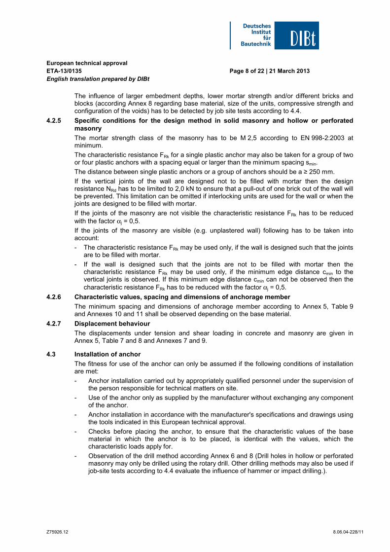
European technical approval ETA-130135 English translation prepared by DIBt
Page 9 of 22 | 21 March 2013
Z7592612 80604-22811
- Placing drill holes without damaging the reinforcement
- Observation of the overall plastic anchor embedment depth
- Holes to be cleaned of drilling dust
- In case of aborted hole New drilling at a minimum distance away of twice the depth of the aborted hole or smaller distance if the aborted drill hole is filled with high strength mortar
- The plastic sleeve is inserted through the fixture by slight hammer blows and the special screw is screwed in until the head of the screw touches the sleeve The anchor is correct mounted if there is no turn-through of the plastic sleeve in the drill hole and if slightly move on turning of the screw is impossible after the complete turn-in of the screw
- Temperature during installation of the anchor ge 0 degC (plastic sleeve and base material)
44 Job site tests according to ETAG 020 Annex B
441 General
In the absence of national requirements the characteristic resistance of the plastic anchor may be determined by job site tests if the plastic anchor has already characteristic values given in Annex 4 6 and 8 for the same base material as it is present on the construction works
Furthermore job site tests for use in different concrete solid masonry and hollow or perforated masonry are possible only if the plastic anchor has already characteristic values given in Annex 4 6 and 8 for use in the equivalent base material
Job site tests are also possible if another drill method is been used as it is given in Annex 6 and 8
The characteristic resistance to be applied to a plastic anchor should be determined by means of at least 15 pull-out tests carried out on the construction work with a centric tension load acting on the plastic anchor These tests may also performed in a laboratory under equivalent conditions as used on construction work
Execution and evaluation of the tests as well as issue of the test report and determination of the characteristic resistance should be supervised by the person responsible for execution of works on site and be carried out by a competent person
Number and position of the plastic anchors to be tested should be adapted to the relevant special conditions of the construction work in question and for example in the case of blind and larger areas be increased such that a reliable information about the characteristic resistance of the plastic anchor embedded in the base material in question can be derived The tests should take account of the unfavourable conditions of practical execution
442 Assembly
The plastic anchor to be tested shall be installed (e g preparation of drill hole drilling tool to be used drill bit type of drilling hammer or rotation thickness of fixture) and as far as spacing and edge distances are concerned be distributed in the same way as foreseen for the intended use
Depending on the drilling tool hard metal hammer drill bits or hard metal percussion drill bits respectively according to ISO 5468 should be used New drill bits should be used for one test series or drill bits with dcutm = 825 mm lt dcut le 845 mm = dcutmax or dcutm = 1025 mm lt dcut le 1045 mm = dcutmax respective
European technical approval ETA-130135 English translation prepared by DIBt
Page 10 of 22 | 21 March 2013
Z7592612 80604-22811
443 Execution of test
The test rig used for the pull-out tests shall provide a continuous slow increase of the load controlled by a calibrated load cell The load shall apply perpendicular to the surface of the base material and shall be transmitted to the anchor via a hinge The reaction forces shall be transmitted into the base material such that possible breakout of the masonry is not restricted This condition is considered as fulfilled if the support reaction forces are transmitted either in adjacent masonry units or at a distance of at least 150 mm from the plastic anchors The load shall be increased continuously in a way that the ultimate load is reached after about 1 minute The load is measured when the ultimate load (N1) is achieved
If no pull-out failure occurs other test methods are needed eg proof-loading
444 Test report
The test report shall include all information necessary to assess the resistance of the tested anchor It shall be given to the person responsible for the design of the fastening and shall be included in the construction dossier
The minimum data required are
- Name of product
- Construction site owner of building date and location of the tests air temperature
- Test rig
- Type of structure to be fixed
- Base material (eg type of brick strength class all dimensions of bricks mortar group if possible) visual assessment of masonry (flush joints joint clearance regularity)
- Plastic anchor and special screw
- value of the cutting diameter of hard metal hammer-drill bits measured before and after drilling if no new drill bits are used
- Results of tests including the indication of value N1 mode of failure
- Tests carried out or supervised by hellip signature
445 Evaluation of test results
The characteristic resistance FRk1 is derived from the measured values N1 as follows
FRk1 = 05N1
The characteristic resistance FRk1 has to be equal or smaller than the characteristic resistance FRk which is given in the ETA for the equivalent base material
N1 = the mean value of the five smallest measured values at ultimate load
In absence of national regulations the partial safety factors for the resistance of the plastic anchor may be taken as γMc = 18 for use in concrete and γMm = 25 for use in masonry
European technical approval ETA-130135 English translation prepared by DIBt
Page 11 of 22 | 21 March 2013
Z7592612 80604-22811
5 Indications to the manufacturer
51 Responsibility of the manufacturer
It is in the responsibility of the manufacturer to ensure that the information on the specific conditions according to 1 and 2 including Annexes referred to 4 is given to those who are concerned This information may be made by reproduction of the respective parts of the European technical approval In addition all installation data shall be shown clearly on the packaging andor on an enclosed instruction sheet preferably using illustrations
The minimum data required are
- base material for the intended use
- ambient temperature of the base material during installation of the anchor
- drill bit diameter (dcut)
- overall anchor embedment depth in the base material (hnom)
- minimum hole depth (h0)
- information on the installation procedure
- identification of the manufacturing batch
All data shall be presented in a clear and explicit form
52 Packaging transport and storage
The anchor shall only be packaged and supplied as a complete unit
The anchor shall be stored under normal climatic conditions in its original light-proof packaging Before installation it shall not be extremely dried nor frozen
Andreas Kummerow beglaubigt
p p Head of Department Buumlrger
Page 12 of European technical approval ETA-130135 of 21 March 2013 English translation prepared by DIBt
Z2351513 80604-22811
Page 13 of European technical approval ETA-130135 of 21 March 2013 English translation prepared by DIBt
Z2351513 80604-22811
Page 14 of European technical approval ETA-130135 of 21 March 2013 English translation prepared by DIBt
Z2351513 80604-22811
Page 15 of European technical approval ETA-130135 of 21 March 2013 English translation prepared by DIBt
Z2351513 80604-22811
Page 16 of European technical approval ETA-130135 of 21 March 2013 English translation prepared by DIBt
Z2351513 80604-22811
Page 17 of European technical approval ETA-130135 of 21 March 2013 English translation prepared by DIBt
Z2351513 80604-22811
Page 18 of European technical approval ETA-130135 of 21 March 2013 English translation prepared by DIBt
Z2351513 80604-22811
Page 19 of European technical approval ETA-130135 of 21 March 2013 English translation prepared by DIBt
Z2351513 80604-22811
Page 20 of European technical approval ETA-130135 of 21 March 2013 English translation prepared by DIBt
Z2351513 80604-22811
Page 21 of European technical approval ETA-130135 of 21 March 2013 English translation prepared by DIBt
Z2351513 80604-22811
Page 22 of European technical approval ETA-130135 of 21 March 2013 English translation prepared by DIBt
Z2351513 80604-22811
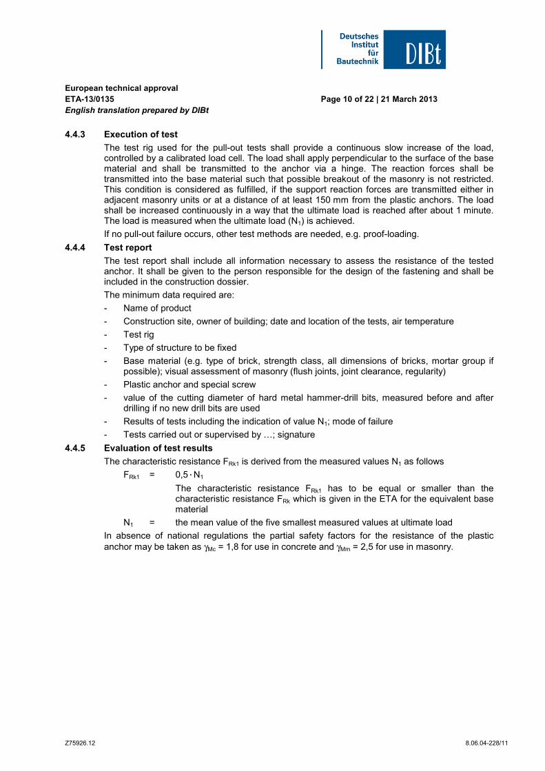
European technical approval ETA-130135 English translation prepared by DIBt
Page 11 of 22 | 21 March 2013
Z7592612 80604-22811
5 Indications to the manufacturer
51 Responsibility of the manufacturer
It is in the responsibility of the manufacturer to ensure that the information on the specific conditions according to 1 and 2 including Annexes referred to 4 is given to those who are concerned This information may be made by reproduction of the respective parts of the European technical approval In addition all installation data shall be shown clearly on the packaging andor on an enclosed instruction sheet preferably using illustrations
The minimum data required are
- base material for the intended use
- ambient temperature of the base material during installation of the anchor
- drill bit diameter (dcut)
- overall anchor embedment depth in the base material (hnom)
- minimum hole depth (h0)
- information on the installation procedure
- identification of the manufacturing batch
All data shall be presented in a clear and explicit form
52 Packaging transport and storage
The anchor shall only be packaged and supplied as a complete unit
The anchor shall be stored under normal climatic conditions in its original light-proof packaging Before installation it shall not be extremely dried nor frozen
Andreas Kummerow beglaubigt
p p Head of Department Buumlrger
Page 12 of European technical approval ETA-130135 of 21 March 2013 English translation prepared by DIBt
Z2351513 80604-22811
Page 13 of European technical approval ETA-130135 of 21 March 2013 English translation prepared by DIBt
Z2351513 80604-22811
Page 14 of European technical approval ETA-130135 of 21 March 2013 English translation prepared by DIBt
Z2351513 80604-22811
Page 15 of European technical approval ETA-130135 of 21 March 2013 English translation prepared by DIBt
Z2351513 80604-22811
Page 16 of European technical approval ETA-130135 of 21 March 2013 English translation prepared by DIBt
Z2351513 80604-22811
Page 17 of European technical approval ETA-130135 of 21 March 2013 English translation prepared by DIBt
Z2351513 80604-22811
Page 18 of European technical approval ETA-130135 of 21 March 2013 English translation prepared by DIBt
Z2351513 80604-22811
Page 19 of European technical approval ETA-130135 of 21 March 2013 English translation prepared by DIBt
Z2351513 80604-22811
Page 20 of European technical approval ETA-130135 of 21 March 2013 English translation prepared by DIBt
Z2351513 80604-22811
Page 21 of European technical approval ETA-130135 of 21 March 2013 English translation prepared by DIBt
Z2351513 80604-22811
Page 22 of European technical approval ETA-130135 of 21 March 2013 English translation prepared by DIBt
Z2351513 80604-22811
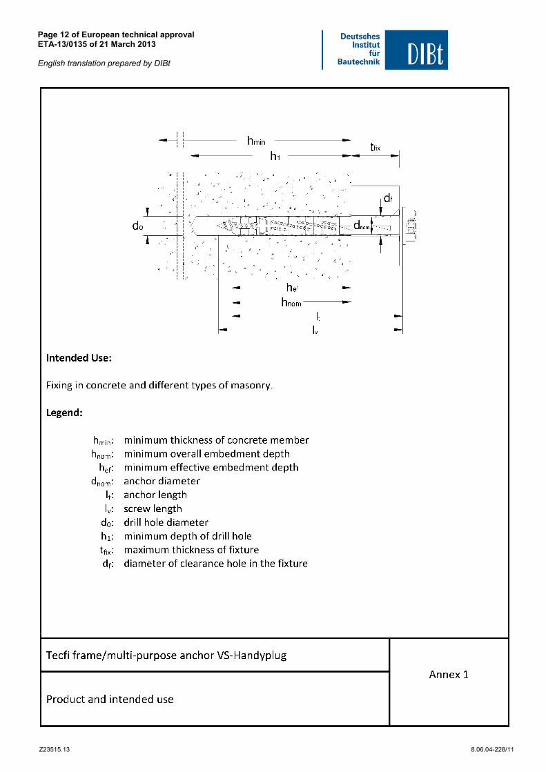
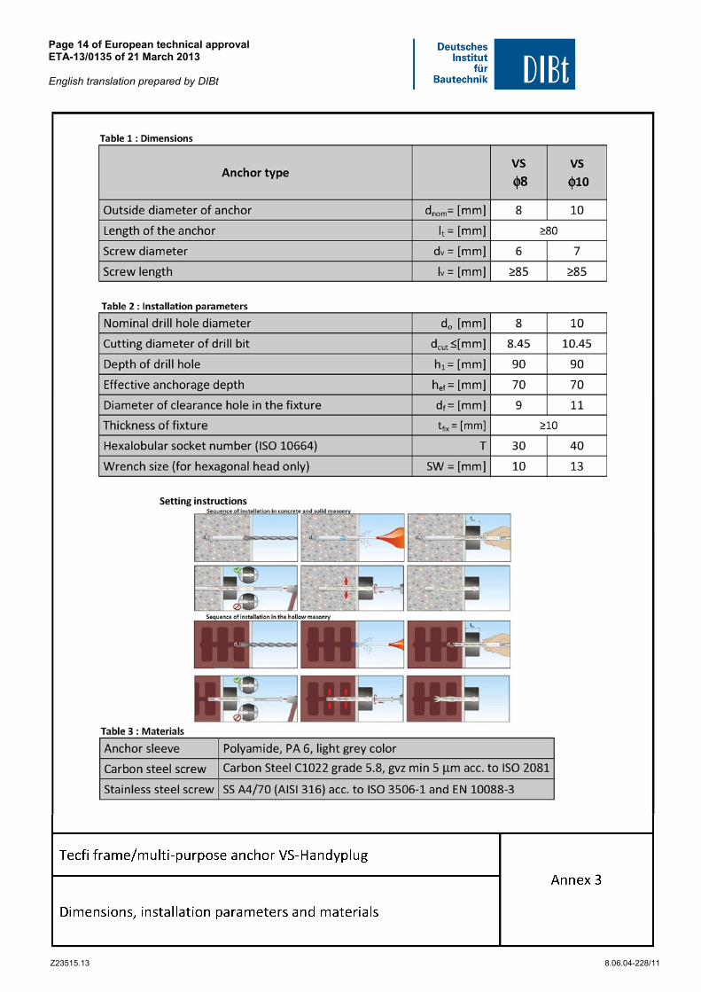
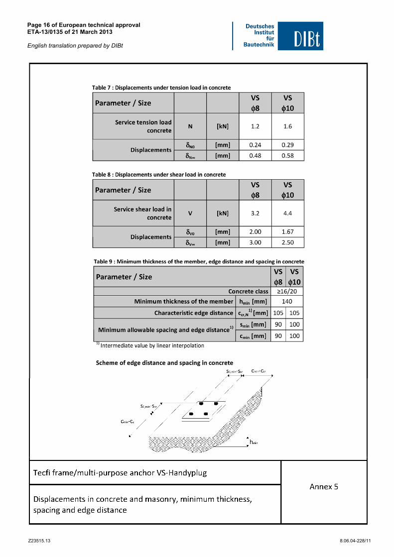
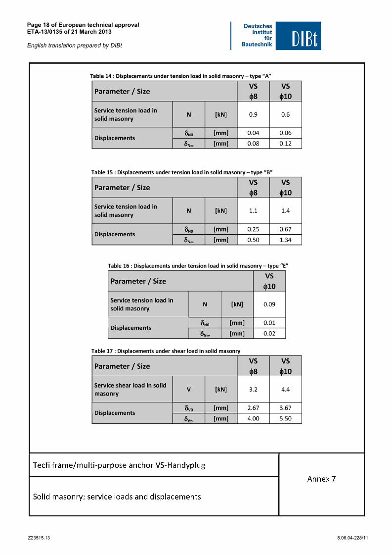
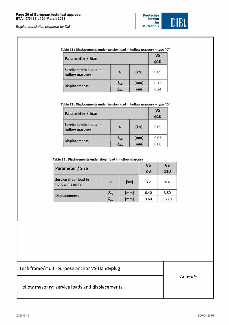

Page 21 of European technical approval ETA-130135 of 21 March 2013 English translation prepared by DIBt
Z2351513 80604-22811
Page 22 of European technical approval ETA-130135 of 21 March 2013 English translation prepared by DIBt
Z2351513 80604-22811

Page 22 of European technical approval ETA-130135 of 21 March 2013 English translation prepared by DIBt
Z2351513 80604-22811