European Aviation Safety Agency - easa.europa.euH... · In the case of helicopters, a full flight...
128
Annex to ED Decision 2012/011/R European Aviation Safety Agency Certification Specifications for Helicopter Flight Simulation Training Devices Initial issue 26 June 2012 ‘CS-FSTD(H)’
Transcript of European Aviation Safety Agency - easa.europa.euH... · In the case of helicopters, a full flight...
Annex to ED Decision 2012/011/R
European Aviation Safety Agency
Certification Specifications for Helicopter Flight Simulation Training Devices
Initial issue
26 June 2012
‘CS-FSTD(H)’

Annex to ED Decision 2012/011/R
Page 2 of 128
Table of contents
CS-FSTD(H) Book 1 – Certification Specifications .. Error! Bookmark not defined.
SUBPART A - APPLICABILITY................................................................................ 4
CS FSTD(H).001 Applicability .......................................................................... 4
SUBPART B - TERMINOLOGY ................................................................................ 5
CS FSTD(H).200 Terminology .......................................................................... 5
SUBPART C – HELICOPTER FLIGHT SIMULATION TRAINING DEVICES ....................... 6
CS FSTD(H).300 Qualification basis .................................................................. 6
APPENDICES ...................................................................................................... 7
Appendix 1 to CS FSTD(H).300 Flight Simulation Training Device Standards ......... 7
Appendix 1 to CS FSTD(H).300 (continued) ...................................................... 22
CS-FSTD(H) Book 2 -Acceptable Means of Compliance .................................... 23
SUBPART B – TERMINOLOGY ............................................................................. 24
AMC1 FSTD(H).200 Terminology and abbreviations .......................................... 24
SUBPART C – HELICOPTER FLIGHT SIMULATION TRAINING DEVICES ..................... 34
AMC1 FSTD(H).300 Qualification basis............................................................ 34
Appendix 1 to AMC1 FSTD(H).300 Validation test tolerances .......................... 94
Appendix 2 to AMC1 FSTD(H).300 Validation data roadmap ........................... 96
Appendix 3 to AMC1 FSTD(H).300 Rotor aerodynamic modelling techniques ..... 98
Appendix 4 to AMC1 FSTD(H).300 Vibration platforms for helicopter FSTDs .... 101
Appendix 5 to AMC1 FSTD(H).300 Transport delay testing method ................ 103
Appendix 6 to AMC1 FSTD(H).300 Recurrent evaluations - validation test data
presentation ............................................................................................. 106
Appendix 7 to AMC1 FSTD(H).300 Applicability of CS-FSTD amendments to FSTD
data packages for existing aircraft .............................................................. 107
Appendix 8 to AMC1 FSTD(H).300 Visual display systems ............................ 109
Appendix 9 to AMC1 FSTD(H).300 General technical requirements for FSTD
qualification levels .................................................................................... 112
AMC2 FSTD(H).300 Guidance on design and qualification of level 'A' helicopter full
flight simulators (FFSs) ................................................................................ 115
AMC3 FSTD(H).300 Guidance on design and qualification of helicopter flight training
devices (FTDs) ............................................................................................ 117
AMC4 FSTD(H).300 Use of data for helicopter flight training devices (FTDs) ...... 120
AMC5 FSTD(H).300 Guidance on design and qualification of helicopter flight and
navigation procedures trainers (FNPTs) .......................................................... 120
AMC6 FSTD(H).300 Engineering simulator validation data ............................... 126
AMC7 FSTD(H).300 Engineering simulator validation data – approval guidelines 126

Annex to ED Decision 2012/011/R
Page 3 of 128
Certification Specifications
for
Helicopter
Flight Simulation Training Devices
CS-FSTD(H)
Book 1

Annex to ED Decision 2012/011/R
Page 4 of 128
SUBPART A - APPLICABILITY
CS FSTD(H).001 Applicability
(a) CS-FSTD(H) as amended applies to approved training organisations operating a flight simulation training device (FSTD) seeking initial qualification of FSTDs.
(b) The version of the CS-FSTD(H) agreed by the competent authority and used for the issue of the initial qualification shall be applicable for future recurrent qualifications of the FSTD, unless recategorised.
Annex to ED Decision 2012/011/R
Page 5 of 128
SUBPART B - TERMINOLOGY
CS FSTD(H).200 Terminology
Because of the technical complexity of FSTD qualification, it is essential that standard terminology is used throughout. The following principal terms and abbreviations should be used in order to comply with CS–FSTD(H). Further terms and abbreviations are contained in AMC1 FSTD(H).200.
(a) ‘Flight simulation training device (FSTD)’ means a training device which is:
In the case of aeroplanes, a full flight simulator (FFS), a flight training device (FTD), a flight navigation procedures trainer (FNPT), or a basic instrument training device (BITD)
In the case of helicopters, a full flight simulator (FFS), a flight training device (FTD) or a flight navigation procedures trainer (FNPT).
(b) ‘Full flight simulator (FFS)’ means a full size replica of a specific type or make, model and series aircraft flight deck/cockpit, including the assemblage of all equipment and computer programmes necessary to represent the aircraft in ground and flight operations, a visual system providing an out of the flight deck/cockpit view, and a force cueing motion system. It is in compliance with the minimum standards for FFS qualification.
(c) ‘Flight training device (FTD)’ means a full size replica of a specific aircraft type’s instruments, equipment, panels and controls in an open flight deck/cockpit area or an enclosed aircraft flight deck/cockpit, including the assemblage of equipment and computer software programmes necessary to represent the aircraft in ground and flight conditions to the extent of the systems installed in the device. It does not require a force cueing motion or visual system. It is in compliance with the minimum standards for a specific FTD level of qualification.
(d) ‘Flight and navigation procedures trainer (FNPT)’ means a training device which represents the flight deck/cockpit environment including the assemblage of equipment and computer programmes necessary to represent an aircraft or class/type of aircraft in flight operations to the extent that the systems appear to function as in an aircraft. It is in compliance with the minimum standards for a specific FNPT level of qualification.
(e) ‘Other training device (OTD)’ means a training aid other than an FSTD which provides for training where a complete flight deck/cockpit environment is not necessary.
(f) ‘Flight simulation training device user (FSTD user)’ means the organisation or person requesting training, checking or testing through the use of an FSTD.
(g) ‘Flight simulation training device qualification (FSTD qualification)’ means the level of technical ability of an FSTD as defined in the compliance document.
(h) ‘Qualification test guide (QTG)’ means a document designed to demonstrate that the performance and handling qualities of an FSTD are within prescribed limits with those of the aircraft, class of aeroplane or type of helicopter and that all applicable requirements have been met. The QTG includes both the data of the aircraft, class of aeroplane or type of helicopter and FSTD data used to support the validation.

Annex to ED Decision 2012/011/R
Page 6 of 128
SUBPART C – HELICOPTER FLIGHT SIMULATION TRAINING DEVICES
CS FSTD(H).300 Qualification basis
(a) Any FSTD submitted for initial evaluation shall be evaluated against applicable CS–FSTD(H) criteria for the qualification levels applied for. Recurrent evaluations of an FSTD shall be based on the same version of CS-FSTD(H) that was applicable for its initial evaluation. An upgrade shall be based on the currently applicable version of CS-FSTD(H).
(b) An FSTD shall be assessed in those areas that are essential to completing the flight crew member training, testing and checking process as applicable.
(c) The FSTD shall be subjected to:
(1) validation tests; and
(2) functions & subjective tests.
(d) The QTG, including all data, supporting material and information should be submitted in a format to allow efficient review and evaluation before the FSTD can gain a qualification level. Where applicable, the QTG should be based on the aircraft validation data as defined by the operational suitability data (OSD) established in accordance with Part-21.
Annex to ED Decision 2012/011/R
Page 7 of 128
APPENDICES
Appendix 1 to CS FSTD(H).300 Flight Simulation Training Device Standards
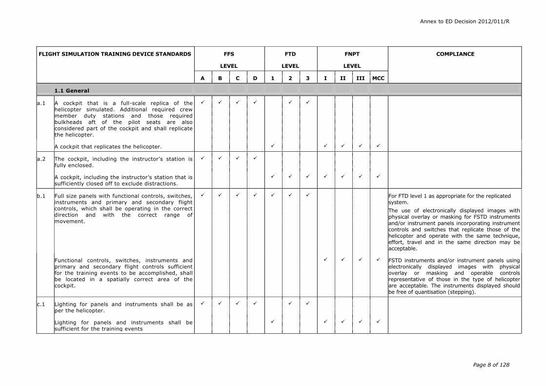
This Appendix describes the minimum full flight simulator (FFS), flight training device (FTD) and flight navigation procedures trainer (FNPT) requirements for qualifying devices to the required qualification levels. Certain requirements included in this CS should be supported with a statement of compliance (SOC) and, in some designated cases, an objective test. The SOC shall describe how the requirement was met. The test results should show that the requirement has been attained. In the following tabular listing of FSTD standards, statements of compliance are indicated in the compliance column.
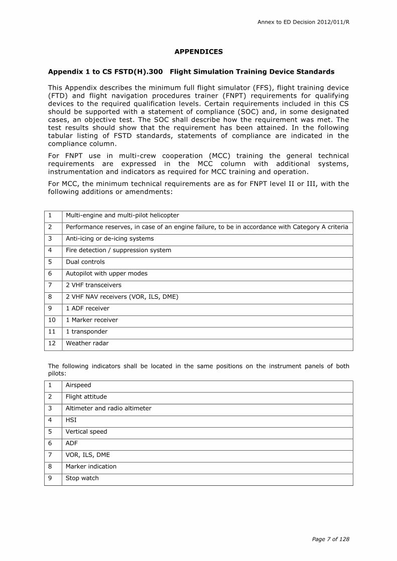
For FNPT use in multi-crew cooperation (MCC) training the general technical requirements are expressed in the MCC column with additional systems, instrumentation and indicators as required for MCC training and operation.
For MCC, the minimum technical requirements are as for FNPT level II or III, with the following additions or amendments:
1 Multi-engine and multi-pilot helicopter
2 Performance reserves, in case of an engine failure, to be in accordance with Category A criteria
3 Anti-icing or de-icing systems
4 Fire detection / suppression system
5 Dual controls
6 Autopilot with upper modes
7 2 VHF transceivers
8 2 VHF NAV receivers (VOR, ILS, DME)
9 1 ADF receiver
10 1 Marker receiver
11 1 transponder
12 Weather radar
The following indicators shall be located in the same positions on the instrument panels of both pilots:
1 Airspeed
2 Flight attitude
3 Altimeter and radio altimeter
4 HSI
5 Vertical speed
6 ADF
7 VOR, ILS, DME
8 Marker indication
9 Stop watch
Annex to ED Decision 2012/011/R
Page 8 of 128
FLIGHT SIMULATION TRAINING DEVICE STANDARDS
FFS FTD FNPT COMPLIANCE
LEVEL LEVEL LEVEL
A B C D 1 2 3 I II III MCC
1.1 General
a.1 A cockpit that is a full-scale replica of the helicopter simulated. Additional required crew member duty stations and those required bulkheads aft of the pilot seats are also considered part of the cockpit and shall replicate the helicopter.
A cockpit that replicates the helicopter.
a.2 The cockpit, including the instructor’s station is fully enclosed.
A cockpit, including the instructor’s station that is sufficiently closed off to exclude distractions.
b.1 Full size panels with functional controls, switches, instruments and primary and secondary flight controls, which shall be operating in the correct direction and with the correct range of
movement.
For FTD level 1 as appropriate for the replicated system.
The use of electronically displayed images with physical overlay or masking for FSTD instruments
and/or instrument panels incorporating instrument controls and switches that replicate those of the helicopter and operate with the same technique, effort, travel and in the same direction may be acceptable.
Functional controls, switches, instruments and primary and secondary flight controls sufficient for the training events to be accomplished, shall be located in a spatially correct area of the cockpit.
FSTD instruments and/or instrument panels using electronically displayed images with physical overlay or masking and operable controls representative of those in the type of helicopter are acceptable. The instruments displayed should be free of quantisation (stepping).
c.1 Lighting for panels and instruments shall be as per the helicopter.
Lighting for panels and instruments shall be sufficient for the training events

Annex to ED Decision 2012/011/R
Page 9 of 128
FLIGHT SIMULATION TRAINING DEVICE STANDARDS
FFS FTD FNPT COMPLIANCE
LEVEL LEVEL LEVEL
A B C D 1 2 3 I II III MCC
c.2 Cockpit ambient lighting environment shall be dynamically consistent with the visual display and sufficient for the training event.
The ambient lighting should provide an even level of illumination which is not distracting to the pilot.
d.1 Relevant cockpit circuit breakers shall be located as per the helicopter and shall function accurately when involved in operating procedures or malfunctions requiring or involving flight crew response.
e.1 Effect of aerodynamic changes for various combinations of airspeed and power normally encountered in flight, including the effect of change in helicopter attitude, aerodynamic and propulsive forces and moments, altitude, temperature, mass, centre of gravity location and configuration.
Effects of Cg, mass and configuration changes are not required for FNPT level I.
Aerodynamic and environment modelling shall be sufficient to permit accurate systems operation and indication.
e.2 Aerodynamic modelling which includes ground
effect, effects of airframe and rotor icing (if applicable), aerodynamic interference effects between the rotor wake and fuselage, influence of the rotor on control and stabilisation systems, and representations of nonlinearities due to sideslip, vortex ring and retreating blade stall.
f.1 Validation flight test data shall be used as the basis for flight and performance and systems characteristics.
Representative/generic aerodynamic data tailored to the helicopter with fidelity sufficient to meet the objective tests and sufficient to permit accurate system operation and indication.
Aerodynamic data need not be necessarily based on flight test data.

Annex to ED Decision 2012/011/R
Page 10 of 128
FLIGHT SIMULATION TRAINING DEVICE STANDARDS
FFS FTD FNPT COMPLIANCE
LEVEL LEVEL LEVEL
A B C D 1 2 3 I II III MCC
g.1 All relevant cockpit instrument indications automatically respond to control movement by a crew member, helicopter performance, or external simulated environmental effects upon the helicopter.
h.1 All relevant communications, navigation, caution and warning equipment shall correspond to that installed in the helicopter. All simulated navigation aids within range shall be usable without restriction. Navigational data shall be capable of being updated.
For FTD 1 applies where the appropriate systems are replicated.
h.2 Navigation equipment corresponding to that of a helicopter, with operation within the tolerances typically applied to the airborne equipment. This shall include communication equipment (interphone and air/ground communications systems).
h.3 Navigational data with the corresponding approach facilities. Navigation aids should be usable within range without restriction.
For FFSs and FTDs the navigation database should be updated within 28 days.
For FNPTs complete navigational data for at
least five different European airports with corresponding precision and non-precision approach procedures including current updating within a period of three months.
i.1 In addition to the flight crew member stations, at least two suitable seats for the instructor and an additional observer shall be provided permitting adequate vision to the crew members’ panel and forward windows. Observer and instructor seats need not represent those found in the helicopter but shall be adequately secured to the floor of the FFS, fitted with positive restraint devices and be of sufficient integrity to safely restrain the occupant during any known or predicted motion system excursion.
The competent authority shall consider options to this standard based on unique cockpit configurations.
Any additional seats installed shall be equipped with similar safety provisions.
Annex to ED Decision 2012/011/R
Page 11 of 128
FLIGHT SIMULATION TRAINING DEVICE STANDARDS
FFS FTD FNPT COMPLIANCE
LEVEL LEVEL LEVEL
A B C D 1 2 3 I II III MCC
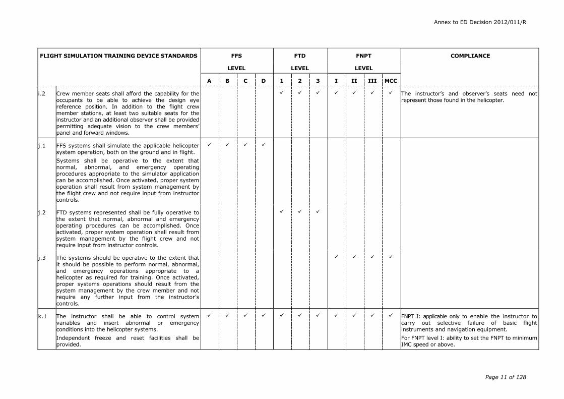
i.2 Crew member seats shall afford the capability for the occupants to be able to achieve the design eye reference position. In addition to the flight crew member stations, at least two suitable seats for the instructor and an additional observer shall be provided permitting adequate vision to the crew members’ panel and forward windows.
The instructor’s and observer’s seats need not represent those found in the helicopter.
j.1 FFS systems shall simulate the applicable helicopter system operation, both on the ground and in flight.
Systems shall be operative to the extent that normal, abnormal, and emergency operating procedures appropriate to the simulator application can be accomplished. Once activated, proper system operation shall result from system management by the flight crew and not require input from instructor controls.
j.2 FTD systems represented shall be fully operative to the extent that normal, abnormal and emergency operating procedures can be accomplished. Once activated, proper system operation shall result from system management by the flight crew and not require input from instructor controls.
j.3 The systems should be operative to the extent that
it should be possible to perform normal, abnormal, and emergency operations appropriate to a helicopter as required for training. Once activated, proper systems operations should result from the system management by the crew member and not require any further input from the instructor’s controls.
k.1 The instructor shall be able to control system variables and insert abnormal or emergency conditions into the helicopter systems.
Independent freeze and reset facilities shall be provided.
FNPT I: applicable only to enable the instructor to carry out selective failure of basic flight instruments and navigation equipment.
For FNPT level I: ability to set the FNPT to minimum IMC speed or above.

Annex to ED Decision 2012/011/R
Page 12 of 128
FLIGHT SIMULATION TRAINING DEVICE STANDARDS
FFS FTD FNPT COMPLIANCE
LEVEL LEVEL LEVEL
A B C D 1 2 3 I II III MCC
l.1 Control forces and control travel which correspond to that of the replicated helicopter. Control forces shall react in the same manner as in the helicopter under the same flight conditions.
For level A only static control force characteristics need to be tested.
Control forces and control travel shall be representative of the replicated helicopter under the same flight conditions as in the helicopter.
For FTD level 1 as appropriate for the system training required.
Control forces and control travel shall broadly correspond to that of a helicopter.
Only static control force characteristics need to be tested.
Control forces and control travels shall respond in the same manner under the same flight conditions as in a helicopter.
Only static control force characteristics need to be tested.
l.2 Cockpit control dynamics, which replicate the helicopter simulated. Free response of the controls shall match that of the helicopter within the given tolerance. Initial and upgrade evaluation shall include
control free response (cyclic, collective, and pedal) measurements recorded at the controls. The measured responses shall correspond to those of the helicopter in ground operations, hover, climb, cruise, and auto-rotation.
For helicopters with irreversible control systems, measurements may be obtained on the ground. Engineering validation or helicopter manufacturer rationale shall be submitted as justification for
ground test or to omit a configuration.
For FFS requiring static and dynamic tests at the controls, special test fixtures shall not be required during the initial evaluations if the FSTD operator’s QTG shows both test fixture results and alternate test method results, such as computer data plots, which were obtained concurrently. Use of the alternate method during initial evaluation may then satisfy this test requirement.
FTD level 2 aerodynamic data can be representative/generic and need not necessarily be based on flight test data.

Annex to ED Decision 2012/011/R
Page 13 of 128
FLIGHT SIMULATION TRAINING DEVICE STANDARDS
FFS FTD FNPT COMPLIANCE
LEVEL LEVEL LEVEL
A B C D 1 2 3 I II III MCC
m.1 Ground handling and aerodynamic programming to include the following:
Ground effect - hover and transition IGE.
(Ground reaction - reaction of the helicopter upon contact with the landing surface during landing to include strut deflections, tire or skid friction, side forces, and other appropriate data, such as weight and speed, necessary to identify the flight condition and configuration.
Ground handling characteristics - control inputs to include braking, deceleration turning radius and the effects of crosswind.
Level A can utilise generic simulation of ground effect and ground handling.
Ground handling and aerodynamic ground effects models should be provided to enable lift-off, hover, and touch down effects to be simulated and harmonised with the sound and visual system.
Generic ground handling and aerodynamic ground effects models should be provided to enable lift-off, hover, and touch down effects to be simulated and harmonised with the sound and visual system.
n.1 Instructor controls for:
(i) wind speed and direction
(ii) turbulence
(iii) other atmospheric models to support the required training
Examples: generic atmospheric models of local wind patterns around mountains and structures.
(iv) adjustment of cloud base and visibility
(v) temperature and barometric pressure.
Annex to ED Decision 2012/011/R
Page 14 of 128
FLIGHT SIMULATION TRAINING DEVICE STANDARDS
FFS FTD FNPT COMPLIANCE
LEVEL LEVEL LEVEL
A B C D 1 2 3 I II III MCC
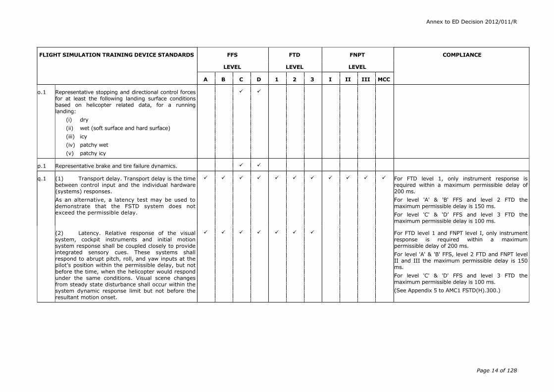
o.1 Representative stopping and directional control forces for at least the following landing surface conditions based on helicopter related data, for a running landing:
(i) dry
(ii) wet (soft surface and hard surface)
(iii) icy
(iv) patchy wet
(v) patchy icy
p.1 Representative brake and tire failure dynamics.
q.1 (1) Transport delay. Transport delay is the time between control input and the individual hardware (systems) responses.
As an alternative, a latency test may be used to demonstrate that the FSTD system does not exceed the permissible delay.
For FTD level 1, only instrument response is required within a maximum permissible delay of 200 ms.
For level 'A' & 'B' FFS and level 2 FTD the maximum permissible delay is 150 ms.
For level 'C' & ‘D’ FFS and level 3 FTD the maximum permissible delay is 100 ms.
(2) Latency. Relative response of the visual system, cockpit instruments and initial motion system response shall be coupled closely to provide integrated sensory cues. These systems shall respond to abrupt pitch, roll, and yaw inputs at the pilot’s position within the permissible delay, but not
before the time, when the helicopter would respond under the same conditions. Visual scene changes from steady state disturbance shall occur within the system dynamic response limit but not before the resultant motion onset.
For FTD level 1 and FNPT level I, only instrument response is required within a maximum permissible delay of 200 ms.
For level 'A' & 'B' FFS, level 2 FTD and FNPT level II and III the maximum permissible delay is 150 ms.
For level 'C' & 'D' FFS and level 3 FTD the maximum permissible delay is 100 ms.
(See Appendix 5 to AMC1 FSTD(H).300.)
Annex to ED Decision 2012/011/R
Page 15 of 128
FLIGHT SIMULATION TRAINING DEVICE STANDARDS
FFS FTD FNPT COMPLIANCE
LEVEL LEVEL LEVEL
A B C D 1 2 3 I II III MCC
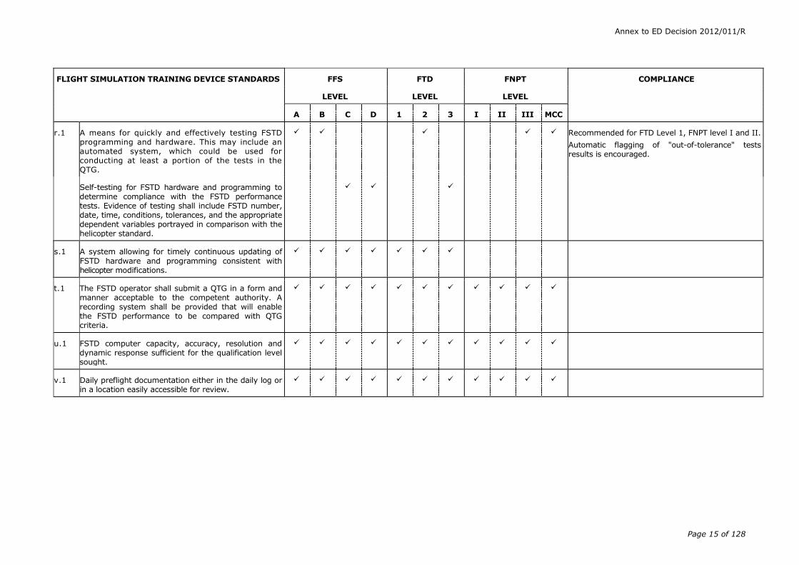
r.1 A means for quickly and effectively testing FSTD programming and hardware. This may include an automated system, which could be used for conducting at least a portion of the tests in the QTG.
Recommended for FTD Level 1, FNPT level I and II.
Automatic flagging of "out-of-tolerance" tests results is encouraged.
Self-testing for FSTD hardware and programming to determine compliance with the FSTD performance tests. Evidence of testing shall include FSTD number, date, time, conditions, tolerances, and the appropriate dependent variables portrayed in comparison with the helicopter standard.
s.1 A system allowing for timely continuous updating of
FSTD hardware and programming consistent with helicopter modifications.
t.1 The FSTD operator shall submit a QTG in a form and manner acceptable to the competent authority. A recording system shall be provided that will enable the FSTD performance to be compared with QTG criteria.
u.1 FSTD computer capacity, accuracy, resolution and dynamic response sufficient for the qualification level sought.
v.1 Daily preflight documentation either in the daily log or in a location easily accessible for review.
Annex to ED Decision 2012/011/R
Page 16 of 128
FLIGHT SIMULATION TRAINING DEVICE STANDARDS
FFS FTD FNPT COMPLIANCE
LEVEL LEVEL LEVEL
A B C D 1 2 3 I II III MCC
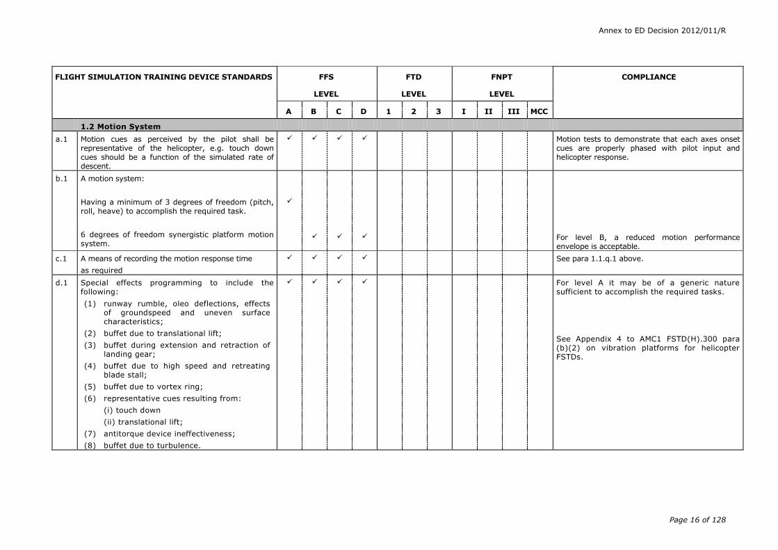
1.2 Motion System
a.1 Motion cues as perceived by the pilot shall be representative of the helicopter, e.g. touch down cues should be a function of the simulated rate of descent.
Motion tests to demonstrate that each axes onset cues are properly phased with pilot input and helicopter response.
b.1 A motion system:
Having a minimum of 3 degrees of freedom (pitch, roll, heave) to accomplish the required task.
6 degrees of freedom synergistic platform motion system.
For level B, a reduced motion performance envelope is acceptable.
c.1 A means of recording the motion response time
as required
See para 1.1.q.1 above.
d.1 Special effects programming to include the following:
(1) runway rumble, oleo deflections, effects of groundspeed and uneven surface characteristics;
(2) buffet due to translational lift;
(3) buffet during extension and retraction of landing gear;
(4) buffet due to high speed and retreating blade stall;
(5) buffet due to vortex ring;
(6) representative cues resulting from:
(i) touch down
(ii) translational lift;
(7) antitorque device ineffectiveness;
(8) buffet due to turbulence.
For level A it may be of a generic nature sufficient to accomplish the required tasks.
See Appendix 4 to AMC1 FSTD(H).300 para (b)(2) on vibration platforms for helicopter FSTDs.

Annex to ED Decision 2012/011/R
Page 17 of 128
FLIGHT SIMULATION TRAINING DEVICE STANDARDS
FFS FTD FNPT COMPLIANCE
LEVEL LEVEL LEVEL
A B C D 1 2 3 I II III MCC
e.1 Characteristic vibrations/buffets that result from operation of the helicopter and which can be sensed in the cockpit. Simulated cockpit vibrations to include seat(s), flight controls and instrument panel(s), although these need not be tested independently.
Statement of compliance required.
Tests required with recorded results which allow the comparison of relative amplitudes versus frequency in the longitudinal, lateral and vertical axes with helicopter data. Steady state tests are acceptable.
See Appendix 4 to AMC1 FSTD(H).300 para (b)(2) on vibration platforms for helicopter FSTDs.
1.3 Visual System
a.1 Visual system capable of meeting all the standards of this paragraph and the respective paragraphs of validation tests as well as functions and subjective tests as applicable to the level of qualification requested by the FSTD operator.
The choice of the display system and of the field of view requirements should fully consider the intended use of the FSTD. The balance between training and testing/checking may influence the choice and geometry of the display system. In addition the diverse operational requirements should be addressed.
b.1 Visual system capable of providing at least a 45 degree horizontal and 30 degree vertical field of view simultaneously for each pilot.
Visual system capable of providing at least a 75 degrees horizontal and 40 degrees vertical field of view simultaneously for each pilot.
“Continuous”, cross-cockpit, minimum visual field of view providing each pilot with 150 degrees horizontal and 40 degrees vertical
A minimum of 75 degrees horizontal field of view on either side of the zero degree azimuth line relative to the helicopter fuselage is required.
b.2 “Continuous,” cross-cockpit, minimum visual field of view providing each pilot with 150 degrees horizontal and 60 degrees vertical.
A minimum of 75 degrees horizontal field of view on either side of the zero degree azimuth line relative to the helicopter fuselage is required. This will allow an offset per side of the horizontal field of view if required for the training.
Where training tasks require extended fields of view beyond the 150 degrees x 60 degrees, then such extended fields of view should be provided.
Annex to ED Decision 2012/011/R
Page 18 of 128
FLIGHT SIMULATION TRAINING DEVICE STANDARDS
FFS FTD FNPT COMPLIANCE
LEVEL LEVEL LEVEL
A B C D 1 2 3 I II III MCC
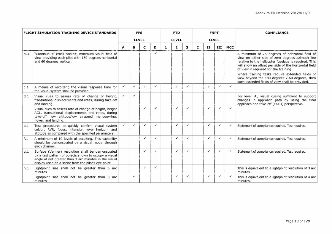
b.3 “Continuous” cross cockpit, minimum visual field of view providing each pilot with 180 degrees horizontal and 60 degrees vertical.
A minimum of 75 degrees of horizontal field of view on either side of zero degrees azimuth line relative to the helicopter fuselage is required. This will allow an offset per side of the horizontal field of view if required for the training.
Where training tasks require extended fields of view beyond the 180 degrees x 60 degrees, then such extended fields of view shall be provided.
c.1 A means of recording the visual response time for the visual system shall be provided.
d.1 Visual cues to assess rate of change of height, translational displacements and rates, during take-off and landing.
For level 'A', visual cueing sufficient to support changes in approach path by using the final approach and take-off (FATO) perspective.
Visual cues to assess rate of change of height, height AGL, translational displacements and rates, during take-off, low altitude/low airspeed manoeuvring, hover, and landing.
e.1 Test procedures to quickly confirm visual system colour, RVR, focus, intensity, level horizon, and attitude as compared with the specified parameters.
Statement of compliance required. Test required.
f.1 A minimum of 10 levels of occulting. This capability should be demonstrated by a visual model through each channel.
Statement of compliance required. Test required.
g.1 Surface (Vernier) resolution shall be demonstrated by a test pattern of objects shown to occupy a visual angle of not greater than 3 arc minutes in the visual display used on a scene from the pilot's eye point.
Statement of compliance required. Test required.
h.1 Lightpoint size shall not be greater than 6 arc minutes
This is equivalent to a lightpoint resolution of 3 arc minutes.
Lightpoint size shall not be greater than 8 arc minutes
This is equivalent to a lightpoint resolution of 4 arc minutes.

Annex to ED Decision 2012/011/R
Page 19 of 128
FLIGHT SIMULATION TRAINING DEVICE STANDARDS
FFS FTD FNPT COMPLIANCE
LEVEL LEVEL LEVEL
A B C D 1 2 3 I II III MCC
i.1 Daylight, dusk, and night visual scenes with sufficient scene content to recognise aerodromes, operating sites, terrain, and major landmarks around the FATO area and to successfully accomplish low airspeed/low altitude manoeuvres to include lift-off, hover, translational lift, landing and touch down.
j.1 A visual database sufficient to support the requirements, including
(i) Specific areas within the database needing higher resolution to support landings, take-offs and ground cushion exercises and training away from an aerodrome/operating site. Including elevated FATO, helidecks and confined areas.
(ii) For cross-country flights sufficient scene details to allow for ground to map navigation over a sector length equal to 30 minutes at an average cruise speed.
(iii) For offshore airborne radar approaches (ARA), harmonised visual/radar representations of installations.
(iv) For training in the use of night vision goggles (NVG) a visual display with the ability to represent various scenes with the required levels of ambient light/colour.
Generic database is acceptable only for FTDs and FNPTs.
Where applicable.
Where applicable.
Where applicable.
k.1 Daylight, twilight (dusk/dawn) and night visual capability for system brightness and contrast ratio criteria as applicable for level of qualification sought.
Night and Dusk scene.
The ambient lighting should provide an even level of illumination, which is not distracting to the pilot.
k.2 The visual system should be capable of producing: Full colour presentations.
Full colour texture shall be used to enhance visual cue perception for illuminated landing surfaces.
Annex to ED Decision 2012/011/R
Page 20 of 128
FLIGHT SIMULATION TRAINING DEVICE STANDARDS
FFS FTD FNPT COMPLIANCE
LEVEL LEVEL LEVEL
A B C D 1 2 3 I II III MCC
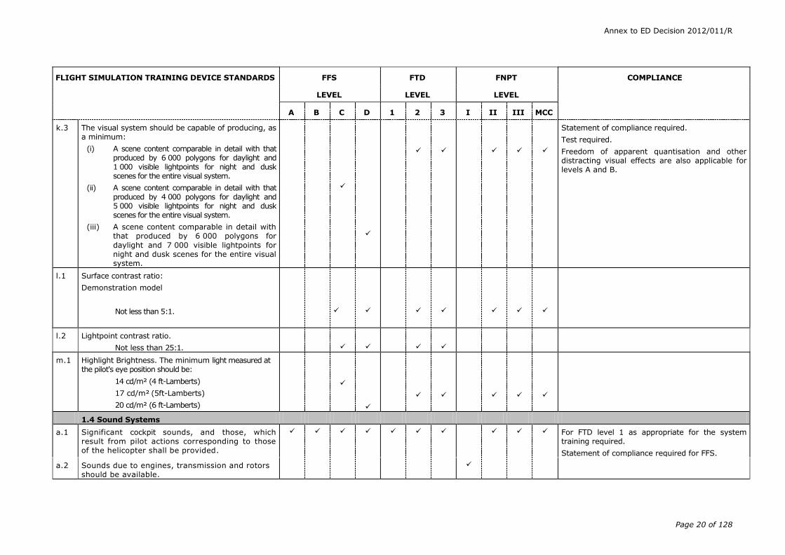
k.3 The visual system should be capable of producing, as a minimum:
(i) A scene content comparable in detail with that produced by 6 000 polygons for daylight and 1 000 visible lightpoints for night and dusk scenes for the entire visual system.
(ii) A scene content comparable in detail with that produced by 4 000 polygons for daylight and 5 000 visible lightpoints for night and dusk scenes for the entire visual system.
(iii) A scene content comparable in detail with that produced by 6 000 polygons for
daylight and 7 000 visible lightpoints for night and dusk scenes for the entire visual system.
Statement of compliance required.
Test required.
Freedom of apparent quantisation and other distracting visual effects are also applicable for levels A and B.
l.1 Surface contrast ratio:
Demonstration model
Not less than 5:1.
l.2 Lightpoint contrast ratio.
Not less than 25:1.
m.1 Highlight Brightness. The minimum light measured at the pilot's eye position should be:
14 cd/m² (4 ft-Lamberts)
17 cd/m² (5ft-Lamberts)
20 cd/m² (6 ft-Lamberts)
1.4 Sound Systems
a.1 Significant cockpit sounds, and those, which result from pilot actions corresponding to those of the helicopter shall be provided.
For FTD level 1 as appropriate for the system training required.
Statement of compliance required for FFS.
a.2 Sounds due to engines, transmission and rotors should be available.
Annex to ED Decision 2012/011/R
Page 21 of 128
FLIGHT SIMULATION TRAINING DEVICE STANDARDS
FFS FTD FNPT COMPLIANCE
LEVEL LEVEL LEVEL
A B C D 1 2 3 I II III MCC
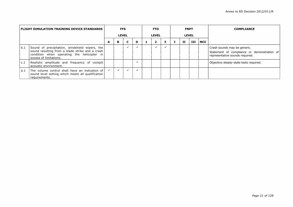
b.1 Sound of precipitation, windshield wipers, the sound resulting from a blade strike and a crash condition when operating the helicopter in excess of limitations.
Crash sounds may be generic.
Statement of compliance or demonstration of representative sounds required.
c.1 Realistic amplitude and frequency of cockpit acoustic environment.
Objective steady-state tests required.
d.1 The volume control shall have an indication of sound level setting which meets all qualification requirements.

Annex to ED Decision 2012/011/R
Page 22 of 128
Appendix 1 to CS FSTD(H).300 (continued)
These standards always refer to the type of helicopter being simulated, except for FNPT, which may be generic. For FNPT, the term “the/a helicopter” is used to represent the aircraft being modelled, which can be a specific helicopter type, a family of similar helicopter types or a totally generic helicopter.
Wherever the term runway is used, it includes runways, FATO and touch down and lift-off (TLOF) areas.
Annex to ED Decision 2012/011/R
Page 23 of 128
Certification Specifications
for
Helicopter
Flight Simulation Training Devices
CS-FSTD(H)
Book 2
Acceptable Means of Compliance

Annex to ED Decision 2012/011/R
Page 24 of 128
A: Rule
SUBPART B – TERMINOLOGY
AMC1 FSTD(H).200 Terminology and abbreviations
(a) Terminology
(1) In addition to the principal terms defined in the requirement itself, additional terms used in the context of CS–FSTD(A) and CS-FSTD(H) have the following meanings:
― ‘Acceptable change’ means a change to configuration, software etc., which qualifies as a potential candidate for alternative approach to validation.
― ‘Aircraft performance data’ means performance data published by the aircraft manufacturer in documents such as the aircraft flight manual (AFM), operations manual, performance engineering manual, or equivalent.
― ‘Airspeed’ means calibrated airspeed when relevant or other airspeed which is clearly annotated.
― ‘Altitude’ means pressure altitude when relevant or other altitude which is clearly annotated.
― ‘Audited engineering simulation’ means an aircraft manufacturer’s engineering simulation which has undergone a review by the appropriate competent authorities and been found to be an acceptable source of supplemental validation data.
― ‘Automatic testing’ means FSTD testing wherein all stimuli are under computer control.
― ‘Bank’ means the bank/roll angle (degrees).
― ‘Baseline’ means a fully flight test validated production aircraft simulation. May represent a new aircraft type or a major derivative.
― ‘Breakout’ means the force required at the pilot’s primary controls to achieve initial movement of the control position.
― ‘Closed loop testing’ means a test method for which the input stimuli are generated by controllers which drive the FSTD to follow a pre-defined target response.
― ‘Computer controlled aircraft’ means an aircraft where the pilot inputs to the control surfaces are transferred and augmented via computers.
― ‘Control sweep’ means a movement of the appropriate pilot’s control from neutral to an extreme limit in one direction (forward, aft, right, or left), a continuous movement back through neutral to the opposite extreme position, and then a return to the neutral position.
― ‘Convertible FSTD’ means an FSTD in which hardware and software can be changed so that the FSTD becomes a replica of a different model or variant, usually of the same type aircraft. The same FSTD platform, cockpit shell, motion system, visual system, computers, and necessary peripheral equipment can thus be used in more than one simulation.
― ‘Critical engine parameter’ means the engine parameter which is the most appropriate measure of the engine power delivered.
― ‘Damping (critical)’ means that minimum damping of a second order system such that no overshoot occurs in reaching a steady state value
Annex to ED Decision 2012/011/R
Page 25 of 128
after being displaced from a position of equilibrium and released. This corresponds to a relative damping ratio of 1:0.
― ‘Damping (over-damped)’: an ‘over-damped’ response is that damping of a second order system such that it has more damping than is required for critical damping, as described above. This corresponds to a relative damping ratio of more than 1:0.
― ‘Damping (under-damped)’: an ‘under-damped’ response is that damping of a second order system such that a displacement from the equilibrium position and free release results in one or more overshoots or oscillations before reaching a steady state value. This corresponds to a relative damping ratio of less than 1:0.
― ‘Daylight visual’ means a visual system capable of meeting, as a minimum, system brightness, contrast ratio requirements and performance criteria appropriate for the level of qualification sought. The system, when used in training, should provide full colour presentations and sufficient surfaces with appropriate textural cues to successfully conduct a visual approach, landing and airport movement (taxi).
― ‘Deadband’ means the amount of movement of the input for a system for which there is no reaction in the output or state of the system observed.
― ‘Driven’ means a state where the input stimulus or variable is ‘driven’ or deposited by automatic means, generally a computer input. The input stimulus or variable may not necessarily be an exact match to the flight test comparison data – but simply driven to certain predetermined values.
― ‘Engineering simulation’ means an integrated set of mathematical models representing a specific aircraft configuration, which is typically used by the aircraft manufacturer for a wide range of engineering analysis tasks including engineering design, development and certification. It is also used to generate data for checkout, proof-of-match/validation and other training FSTD data documents.
― ‘Engineering Simulator’ means the aircraft manufacturer’s simulator which typically includes a full-scale representation of the simulated aircraft flight deck/cockpit, operates in real time and can be flown by a pilot to subjectively evaluate the simulation. It contains the engineering simulation models, which are also released by the aircraft manufacturer to the industry for FSTDs. The engineering simulator may or may not include actual on-board system hardware in lieu of software models.
― ‘Engineering simulator data’ means data generated by an engineering simulation or engineering simulator, depending on the aircraft manufacturer’s processes.
― ‘Engineering simulator validation data’ means validation data generated by an engineering simulation or engineering simulator.
― ‘Entry into service’ refers to the original state of the configuration and systems at the time a new or major derivative aircraft is first placed into commercial operation.
― ‘Essential match’ means a comparison of two sets of computer-generated results for which the differences should be negligible because essentially the same simulation models have been used (also known as a virtual match).
― ‘Flight test data’ means actual aircraft data obtained by the aircraft manufacturer (or other supplier of acceptable data) during an aircraft flight test programme.

Annex to ED Decision 2012/011/R
Page 26 of 128
― ‘Free response’ means the response of the aircraft after completion of a control input or disturbance.
― ‘Frozen/locked’ means a state where a variable is held constant with time.
― ‘FSTD data’ means the various types of data used by the FSTD manufacturer and the applicant to design, manufacture, test and maintain the FSTD.
― ‘FSTD evaluation’ means a detailed appraisal of an FSTD by the competent authority to ascertain whether or not the standard required for a specified qualification level is met.
― ‘FSTD operator’ means that organisation directly responsible to the competent authority for requesting and maintaining the qualification of a particular FSTD.
― ‘Fuel used’ means the mass of fuel used (kilos or pounds).
― ‘Full sweep’ means the movement of the controller from neutral to a stop, usually the aft or right stop, to the opposite stop and then to the neutral position.
― ‘Functional performance’ means an operation or performance that can be verified by objective data or other suitable reference material that may not necessarily be flight test data.
― ‘Functions test’ means a quantitative and/or qualitative assessment of the operation and performance of an FSTD by a suitably qualified evaluator. The test can include verification of correct operation of controls, instruments, and systems of the simulated aircraft under normal and non-normal conditions. Functional performance is that operation or performance that can be verified by objective data or other suitable reference material which may not necessarily be flight test data.
― ‘Grandfather rights’ means the right of an FSTD operator to retain the qualification level granted under a previous regulation of an EASA member state. Also the right of an FSTD user to retain the training and testing/checking credits which were gained under a previous regulation of an EASA Member State.
― ‘Ground effect’ means the change in aerodynamic characteristics due to modification of the air flow past the aircraft caused by the presence of the ground.
― ‘Hands-off manoeuvre’; means a test manoeuvre conducted or completed without pilot control inputs.
― ‘Hands-on manoeuvre’ means a test manoeuvre conducted or completed with pilot control inputs as required.
― ‘Heavy’ means with operational mass at or near maximum for the specified flight condition.
― ‘Height’ means the height above ground (AGL) (meters or feet)
― ‘Highlight brightness’ means the maximum displayed brightness, which satisfies the appropriate brightness test.
― ‘Icing accountability’ means a demonstration of minimum required performance whilst operating in maximum and intermittent maximum icing conditions of the applicable airworthiness requirement. Refers to changes from normal (as applicable to the individual aircraft design) in take-off, climb (en-route, approach, landing) or landing operating procedures or performance data, in accordance with the AFM, for flight in icing conditions or with ice accumulation on unprotected surfaces.
Annex to ED Decision 2012/011/R
Page 27 of 128
― ‘Integrated testing’ means testing of the FSTD such that all aircraft system models are active and contribute appropriately to the results. None of the aircraft system models should be substituted with models or other algorithms intended for testing only. This may be accomplished by using controller displacements as the input. These controllers should represent the displacement of the pilot’s controls and these controls should have been calibrated.
― ‘Irreversible control system’ means a control system in which movement of the control surface will not backdrive the pilot’s control in the cockpit.
― ‘Latency’ means the additional time beyond that of the basic perceivable response time of the aircraft due to the response time of the FSTD.
― ‘Light’ means with operational mass at or near minimum for the specified flight condition.
― ‘Line oriented flight training (LOFT)’ refers to flight crew training which involves full mission simulation of situations which are representative of line operations, with special emphasis on situations which involve communications, management and leadership. It means ‘real-time’, full-mission training.
― ‘Manual testing’ means FSTD testing where the pilot conducts the test without computer inputs except for initial setup. All modules of the simulation should be active.
― ‘Master qualification test guide (MQTG)’ means the competent authority-approved QTG which incorporates the results of tests witnessed by the competent authority. The MQTG serves as the reference for future evaluations.
― ‘Medium’ means the normal operational weight for flight segment.
― ‘Night visual’ means a visual system capable of meeting, as a minimum, the system brightness and contrast ratio requirements and performance criteria appropriate for the level of qualification sought. The system, when used in training, should provide, as a minimum, all features applicable to the twilight scene, as defined below, with the exception of the need to portray reduced ambient intensity that removes ground cues that are not self-illuminating or illuminated by own ship lights (e.g. landing lights).
― ‘Nominal’ means the normal operational weight, configuration, speed etc. for the flight segment specified.
― ‘Non-normal control’ is a term used in reference to computer controlled aircraft. Non-normal control is the state where one or more of the intended control, augmentation or protection functions are not fully available.
(Note: Specific terms such as ALTERNATE, DIRECT, SECONDARY, BACKUP, etc., may be used to define an actual level of degradation).
― ‘Normal control’ is a term used in reference to computer controlled aircraft. Normal control is the state where the intended control, augmentation and protection functions are fully available.
― ‘Objective test (objective testing)’ means a quantitative assessment based on comparison with data.
― ‘One step’ refers to the degree of changes to an aircraft that would be allowed as an acceptable change, relative to a fully flight test validated simulation. The intention of the alternative approach is that changes would be limited to one, rather than a series, of steps away from the baseline configuration. It is understood, however, that those changes which support the primary change (e.g. weight, thrust rating and control system gain

Annex to ED Decision 2012/011/R
Page 28 of 128
changes accompanying a body length change) are considered part of the ‘one step’.
― ‘Power lever angle’ means the angle of the pilot's primary engine control lever(s) in the cockpit. This may also be referred to as PLA, THROTTLE, or POWER LEVER.
― ‘Predicted data’ means data derived from sources other than type-specific aircraft flight tests.
― ‘Primary reference document’ means any regulatory document which has been used by a competent authority to support the initial evaluation of an FSTD.
― ‘Proof-of-match (POM)’ means a document that shows agreement within defined tolerances between model responses and flight test cases at identical test and atmospheric conditions.
― ‘Protection functions’ means systems functions designed to protect an aircraft from exceeding its flight and manoeuvre limitations.
― ‘Pulse input’ means an abrupt input to a control followed by an immediate return to the initial position.
― ‘Reversible control system’ means a partially powered or unpowered control system in which movement of the control surface will backdrive the pilot’s control on the cockpit and/or affect its feel characteristics.
― ‘Robotic test’ means a basic performance check of a system’s hardware and software components. Exact test conditions are defined to allow for repeatability. The components are tested in their normal operational configuration and may be tested independently of other system components.
― ‘Snapshot’ means a presentation of one or more variables at a given instant of time.
― ‘Statement of compliance (SOC)’ means a declaration that specific requirements have been met.
― ‘Step input’ means an abrupt input held at a constant value.
― ‘Subjective test (subjective testing)’ means a qualitative assessment based on established standards as interpreted by a suitably qualified person.
― ‘Throttle lever angle (TLA)’ means the angle of the pilot’s primary engine control lever(s) on the cockpit.
― ‘Time history’ means a presentation of the change of a variable with respect to time.
― ‘Transport delay’ means the total FSTD system processing time required for an input signal from a pilot primary flight control until the motion system, visual system, or instrument response. It is the overall time delay incurred from signal input until output response. It does not include the characteristic delay of the aircraft simulated.
― ‘Twilight (dusk/dawn) visual’ means a visual system capable of meeting, as a minimum, the system brightness and contrast ratio requirements and performance criteria appropriate for the level of qualification sought. The system, when used in training, should provide, as a minimum, full colour presentations of reduced ambient intensity (as compared with a daylight visual system), sufficient to conduct a visual approach, landing and airport movement (taxi).
― ‘Update’ means the improvement or enhancement of an FSTD.
Annex to ED Decision 2012/011/R
Page 29 of 128
― ‘Upgrade’ means the improvement or enhancement of an FSTD for the purpose of achieving a higher qualification.
― ‘Validation data’ means data used to prove that the FSTD performance corresponds to that of the aircraft, class of aeroplane or type of helicopter
― ‘Validation flight test data’ means performance, stability and control, and other necessary test parameters electrically or electronically recorded in an aircraft using a calibrated data acquisition system of sufficient resolution and verified as accurate by the organisation performing the test to establish a reference set of relevant parameters to which like FSTD parameters can be compared.
― ‘Validation test’ means a test by which FSTD parameters can be compared with the relevant validation data.
― ‘Vibration’ means a permanent effect resulting from airframe interaction with rotor, engine or transmission, as opposed to buffet which is a transient vibration effect resulting from either pilot action or aerodynamic effect on the airframe.
― ‘Visual ground segment test’ means a test designed to assess items impacting the accuracy of the visual scene presented to the pilot at a decision height (DH) on an ILS approach.
― ‘Visual system response time’ means the interval from an abrupt control input to the completion of the visual display scan of the first video field containing the resulting different information.
― ‘Well-understood effect’ means an incremental change to a configuration or system which can be accurately modelled using proven predictive methods based on known characteristics of the change.
(b) Abbreviations
A = aeroplane
AC = Advisory Circular
ACJ = Advisory Circular Joint
A/C = aircraft
Ad = total initial displacement of pilot controller (initial displacement to final ADF = automatic direction finder resting amplitude)
AFM = aircraft flight manual
AFCS = automatic flight control system
AGL = above ground level (metres or feet)
An = sequential amplitude of overshoot after initial X axis crossing, e.g. A1 = 1st overshoot.
AEO = all engines operating
AOA = angle of attack (degrees)
ARA = airborne radar approach
ATO = approved training organisation
BC = ILS localiser back course
Annex to ED Decision 2012/011/R
Page 30 of 128
CAT I/II/III = landing category operations
CCA = computer controlled aeroplane
CCH = computer controlled helicopter
cd/m2 = candela/metre2, 3·4263 candela/m2 = 1 ft-Lambert
CG = centre of gravity
cm(s) = centimetre, centimetres
CS = Certification Specifications
CT&M = correct trend and magnitude
daN = decaNewtons
dB = decibel
deg(s) = degree, degrees
DGPS = differential global positioning system
DH = decision height
DME = distance measuring equipment
DPATO = defined point after take-off
DPBL = define point before landing
EPR = engine pressure ratio
EW = empty weight
FAA = United States Federal Aviation Administration
FATO = final approach and take-off
FD = flight director
FOV = field of view
FPM = feet per minute
ft = feet, 1 foot = 0·304801 metres
ft-Lambert = foot-Lambert, 1 ft-Lambert = 3·4263 candela/m2
g = acceleration due to gravity (m or ft/s2), 1g = 9·81 m/s2 or
32·2 ft/s2
G/S = glideslope
GPS = global positioning system
GPWS = ground proximity warning system
H = helicopter
HGS = head-up guidance system
HSI = horizontal situation indicator
IATA = International Air Transport Association
ICAO = International Civil Aviation Organisation
IGE = in ground effect
ILS = instrument landing system
IMC = instrument meteorological conditions
in = inches, 1 in = 2·54 cm

Annex to ED Decision 2012/011/R
Page 31 of 128
IOS = instructor operating station
IPOM = integrated proof of match
IQTG = International Qualification Test Guide (RAeS Document)
km = kilometres, 1 km = 0·62137 statute miles
kPa = kiloPascal (kiloNewton/metres2). 1 psi = 6·89476 kPa
kts = knots calibrated airspeed unless otherwise specified, 1 knot = 0·5148 m/s or 1·689 ft/s
lb = pounds
LOC = localiser
LOFT = line oriented flight training
LOS = line oriented simulation
LDP = landing decision point
m = metres, 1 metre = 3.28083 ft
MCC = multi-crew cooperation
MCTM = maximum certificated take-off mass (kilos/pounds)
MEH = multi-engined helicopter
min = minutes
MLG = main landing gear
mm = millimetres
MPa = megaPascals [1 psi = 6894·76 pascals]
MQTG = master qualification test guide
ms = millisecond(s)
MTOW = maximum take-off weight
n = sequential period of a full cycle of oscillation
N = NORMAL CONTROL Used in reference to computer controlled aircraft
N/A = not applicable
N1 = engine low pressure rotor revolutions per minute expressed in per cent of maximum
N1/Ng = gas generator speed
N2 = engine high pressure rotor revolutions per minute expressed in per cent of maximum
N2/Nf = free turbine speed
NDB = non-directional beacon
NM = nautical mile, 1 nautical mile = 6 080 ft = 1 852 m
NN = non-normal control a state referring to computer controlled aircraft
NR = main rotor speed
NWA = nosewheel angle (degrees)
OEI = one-engine-inoperative
Annex to ED Decision 2012/011/R
Page 32 of 128
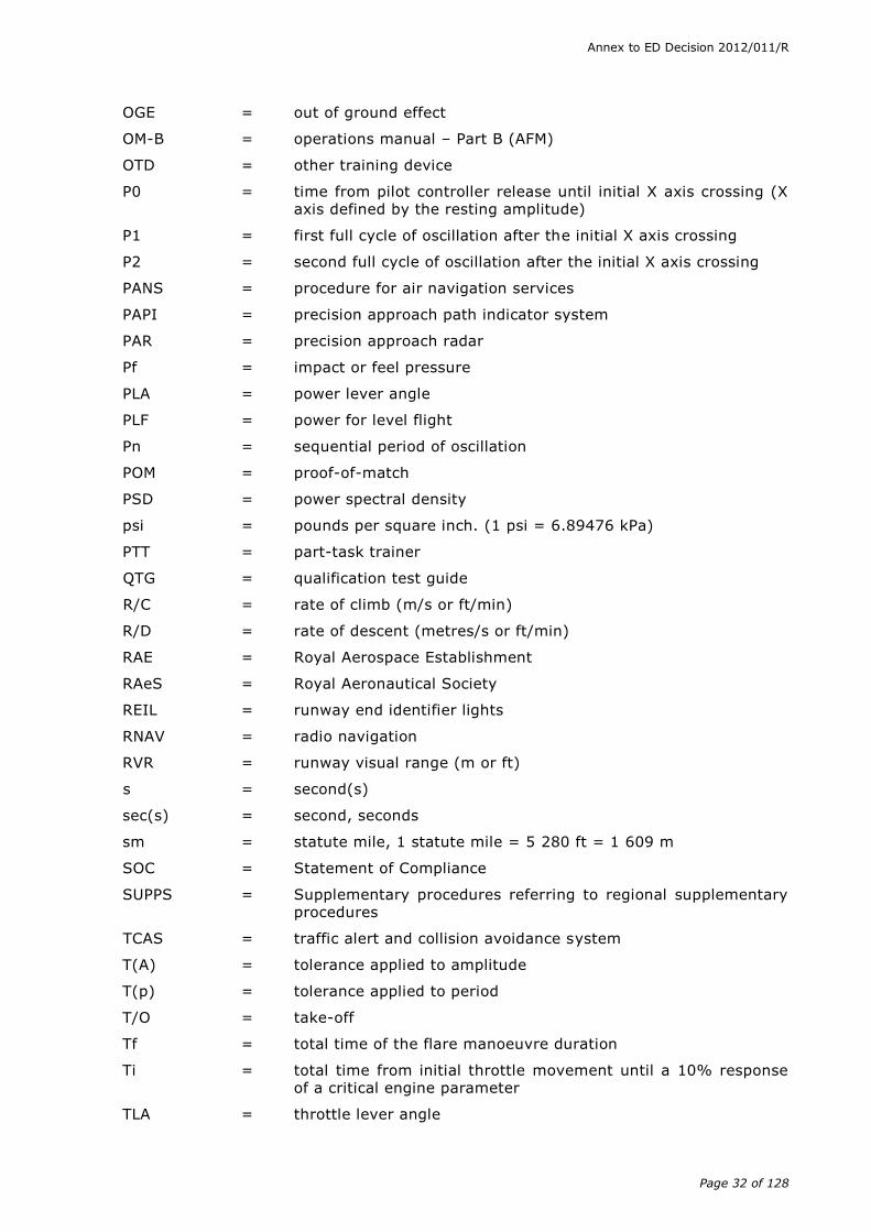
OGE = out of ground effect
OM-B = operations manual – Part B (AFM)
OTD = other training device
P0 = time from pilot controller release until initial X axis crossing (X axis defined by the resting amplitude)
P1 = first full cycle of oscillation after the initial X axis crossing
P2 = second full cycle of oscillation after the initial X axis crossing
PANS = procedure for air navigation services
PAPI = precision approach path indicator system
PAR = precision approach radar
Pf = impact or feel pressure
PLA = power lever angle
PLF = power for level flight
Pn = sequential period of oscillation
POM = proof-of-match
PSD = power spectral density
psi = pounds per square inch. (1 psi = 6.89476 kPa)
PTT = part-task trainer
QTG = qualification test guide
R/C = rate of climb (m/s or ft/min)
R/D = rate of descent (metres/s or ft/min)
RAE = Royal Aerospace Establishment
RAeS = Royal Aeronautical Society
REIL = runway end identifier lights
RNAV = radio navigation
RVR = runway visual range (m or ft)
s = second(s)
sec(s) = second, seconds
sm = statute mile, 1 statute mile = 5 280 ft = 1 609 m
SOC = Statement of Compliance
SUPPS = Supplementary procedures referring to regional supplementary procedures
TCAS = traffic alert and collision avoidance system
T(A) = tolerance applied to amplitude
T(p) = tolerance applied to period
T/O = take-off
Tf = total time of the flare manoeuvre duration
Ti = total time from initial throttle movement until a 10% response of a critical engine parameter
TLA = throttle lever angle
Annex to ED Decision 2012/011/R
Page 33 of 128
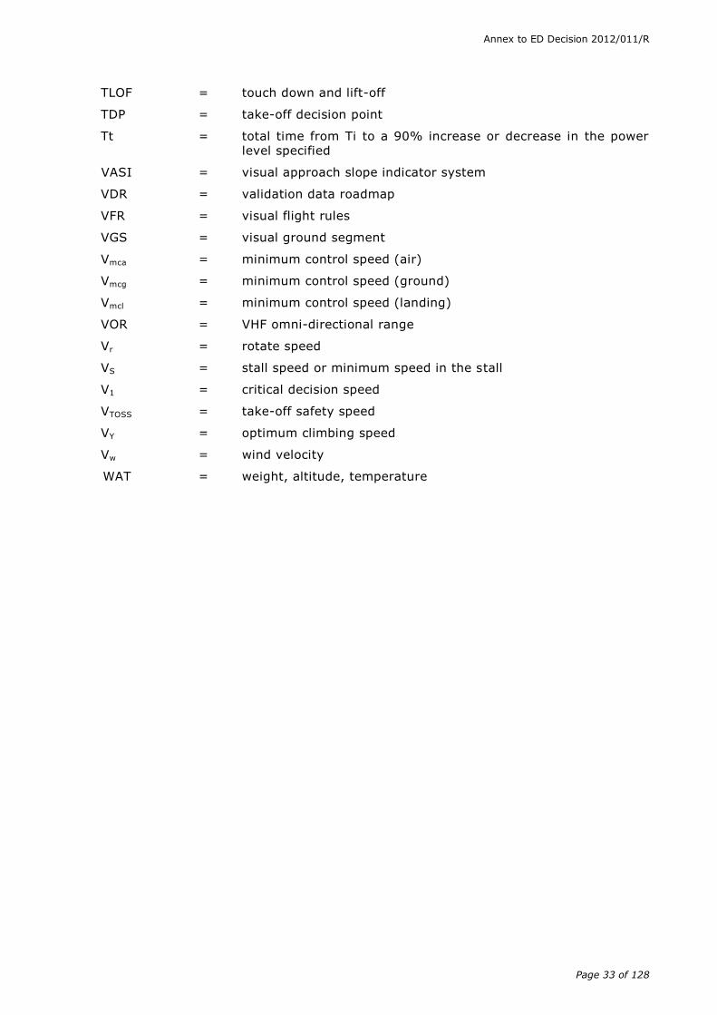
TLOF = touch down and lift-off
TDP = take-off decision point
Tt = total time from Ti to a 90% increase or decrease in the power level specified
VASI = visual approach slope indicator system
VDR = validation data roadmap
VFR = visual flight rules
VGS = visual ground segment
Vmca = minimum control speed (air)
Vmcg = minimum control speed (ground)
Vmcl = minimum control speed (landing)
VOR = VHF omni-directional range
Vr = rotate speed
VS = stall speed or minimum speed in the stall
V1 = critical decision speed
VTOSS = take-off safety speed
VY = optimum climbing speed
Vw = wind velocity
WAT = weight, altitude, temperature
Annex to ED Decision 2012/011/R
Page 34 of 128
SUBPART C – HELICOPTER FLIGHT SIMULATION TRAINING DEVICES
AMC1 FSTD(H).300 Qualification basis
(a) Introduction
(1) Purpose
This AMC establishes the criteria that define the performance and documentation requirements for the evaluation of FSTDs used for training, testing and checking of flight crew members. These test criteria and methods of compliance were derived from extensive experience of competent authorities and the industry.
(2) Background
(i) The availability of advanced technology has permitted greater use of FSTDs for training, testing and checking of flight crew members. The complexity, costs and operating environment of modern aircraft also encourages broader use of advanced simulation. FSTDs can provide more in-depth training than can be accomplished in aircraft and provide a safe and suitable learning environment. Fidelity of modern FSTDs is sufficient to permit pilot assessment with the assurance that the observed behaviour will transfer to the aircraft. Fuel conservation and reduction in adverse environmental effects are important by-products of FSTD use.
(ii) The methods, procedures, and testing criteria contained in this AMC are the result of the experience and expertise of competent authorities, operators, helicopter and FSTD manufacturers.
(3) Levels of FSTD qualification
Subparagraphs (b) and (c) of this AMC describe the minimum requirements for qualifying level A, B, C and D helicopter FFS, level 1, 2 and 3 helicopter FTDs and FNPT levels I, II, II MCC, III and III MCC for generic helicopters.
Note: Where an FTD level 1 simulates a single helicopter system, it should comply with the subjective and objective tests relevant to that system.
(4) Terminology
Terminology and abbreviations of terms used in this AMC are contained in AMC1 FSTD(H).200.
(5) Testing for FSTD qualification
(i) The FSTD should be assessed in those areas which are essential to completing the flight crew-member training, testing and checking process. This includes the FSTD’s longitudinal and lateral-directional responses; performance in take-off, hover, climb, cruise, descent, approach, touch down; specific operations; control checks; cockpit and instructor station functions checks; and certain additional requirements depending on the complexity or qualification level of the FSTD. The motion and visual systems (where applicable) should be evaluated to ensure their proper operation.
(ii) For FFSs and FTDs the intent is to evaluate the FSTD as objectively as possible. Pilot acceptance, however, is also an important consideration. Therefore, the FSTD should be subjected to validation, and functions and subjective tests listed in subparagraphs (b) and (c) of this AMC.
Validation tests are used to compare objectively FFSs and FTDs with aircraft data to ensure that they agree within specified tolerances. Functions and subjective tests provide a basis for evaluating FSTD capability to perform over a typical training period and to verify correct operation of the FSTD.

Annex to ED Decision 2012/011/R
Page 35 of 128
(iii) Tolerances listed for parameters in the validation tests (paragraph (b)) of this AMC are the maximum acceptable for FSTD qualification and should not be confused with FSTD design tolerances.
(iv) For initial qualification of FFSs and FTDs helicopter manufacturer’s validation flight test data is preferred. Data from other sources may be used, subject to the review and concurrence of the competent authority.
(v) For FNPTs generic data packages can be used; for an initial evaluation only correct trend and magnitude (CT&M) should be used. The tolerances listed in this AMC are applicable for recurrent evaluations and should be applied to ensure the device remains at the standard initially qualified.
For initial qualification testing of FNPTs, validation data should be used. They may be derived from a specific helicopter within the type of helicopter the FNPT is representing or they may be based on information from several helicopters within the type. With the concurrence of the competent authority, it may be in the form of a manufacturer’s previously approved set of validation data for the applicable FNPT. Once the set of data for a specific FNPT has been accepted and approved by the competent authority, it will become the validation data that should be used as reference for subsequent recurrent evaluations with the application of the stated tolerances.
The substantiation of the set of data used to build the validation data should be in the form of an engineering report and should show that the proposed validation data are representative of the helicopter or the type of helicopter modelled. This report may include flight test data, manufacturer’s design data, information from the aircraft flight manual and maintenance manuals, results of approved or commonly accepted simulations or predictive models, recognised theoretical results, information from the public domain, subjective assessment of a qualified pilot or other sources as deemed necessary by the FSTD manufacturer to substantiate the proposed model.
(vi) In the case of new aircraft programmes, the aircraft manufacturer’s data, partially validated by flight test data, may be used in the interim qualification of the FSTD. This is consistent with the possible interim approval of operational suitability data (OSD) relative to FFS in the type certification process under Part-21. However, the FSTD should be re-evaluated following the release of the manufacturer’s final data in accordance with the final definition of scope of the aircraft validation source data to support the objective qualification of the OSD as approved under Part-21. The schedule should be as agreed by the competent authority, FSTD operator, FSTD manufacturer, and aircraft manufacturer.
(vii) FSTD operators seeking initial or upgrade evaluation of an FSTD should be aware that performance and handling data for older aircraft may not be of sufficient quality to meet some of the test standards contained in this AMC. In this instance it may be necessary for an operator to acquire additional flight test data.
(viii) During FSTD evaluation, if a problem is encountered with a particular validation test, the test may be repeated to ascertain if the problem was caused by test equipment or FSTD operator error. Following this, if the test problem persists, an FSTD operator should be prepared to offer an alternative test.
(xi) Validation tests that do not meet the test criteria should be addressed to the satisfaction of the competent authority.
Annex to ED Decision 2012/011/R
Page 36 of 128
(6) Qualification test guide (QTG)
(i) The QTG is the primary reference document used for evaluating an FSTD. It contains test results, statements of compliance and other information for the evaluator to assess if the FSTD meets the test criteria described in this AMC.
(ii) The FSTD operator should submit a QTG which includes the following:
(A) A title page with FSTD operator and approval authority signature blocks.
(B) An FSTD information page (for each configuration in the case of convertible FSTDs) providing:
(a) FSTD operator’s FSTD identification number;
(b) helicopter model and series being simulated;
(c) references to aerodynamic data or sources for aerodynamic model;
(d) references to engine data or sources for engine model;
(e) references to flight control data or sources for flight controls model;
(f) avionic equipment system identification where the revision level affects the training and checking capability of the FSTD;
(g) FSTD model and manufacturer;
(h) date of FSTD manufacture;
(i) FSTD computer identification;
(j) visual system type and manufacturer (if fitted); and
(k) motion system type and manufacturer (if fitted).
(C) Table of contents.
(D) List of effective pages and log of test revisions.
(E) Listing of all reference and source data.
(F) Glossary of terms and symbols used.
(G) Statements of compliance (SOC) with certain requirements. SOCs should refer to sources of information and show compliance rationale to explain how the referenced material is used, applicable mathematical equations and parameter values, and conclusions reached.
(H) Recording procedures and required equipment for the validation tests.
(I) The following items are required for each validation test:
(a) Test title: this should be short and definitive, based on the test title referred to in paragraph (b)(3) of this AMC;
(b) Test objective: this should be a brief summary of what the test is intended to demonstrate;
(c) Demonstration procedure: this is a brief description of how the objective is to be met;
(d) References: these are the helicopter data source documents including both the document number and the page or condition number;
Annex to ED Decision 2012/011/R
Page 37 of 128
(e) Initial conditions: a full and comprehensive list of the test initial conditions;
(f) Manual test procedures: procedures should be sufficient to enable the test to be flown by a qualified pilot, using reference to cockpit instrumentation and without reference to other parts of the QTG or flight test data or other documents;
(g) Automatic test procedures (if applicable);
(h) Evaluation criteria: specify the main parameter(s) under scrutiny during the test;
(i) Expected result(s): the helicopter result, including tolerances and, if necessary, a further definition of the point at which the information was extracted from the source data;
(j) Test result: dated FSTD validation test results obtained by the FSTD operator. Tests run on a computer which is independent of the FSTD are not acceptable;
(k) Source data: copy of the helicopter source data (in the case of FFS/FTD) or other validation data (in the case of FNPT), clearly marked with the document, page number, issuing authority, and the test number and title as specified in (a)(6)(ii)(I) above. Computer-generated displays of flight test data (in the case of FFS, FTD) or other validation data (in the case of FNPT) overplotted with FSTD data are insufficient on their own for this requirement. As applicable, the source data should be the data as defined by the OSD established in accordance with Part-21;
(l) Comparison of results: an acceptable means of easily comparing FSTD test results with the validation flight test data.
(m) The preferred method is overplotting. The FSTD operator’s FSTD test results should be recorded on a multi-channel recorder, line printer, electronic capture and display or other appropriate recording media acceptable to the competent authority conducting the test. FSTD results should be labelled using terminology common to helicopter parameters as opposed to computer software identifications. These results should be easily compared with the supporting data by employing cross plotting or other acceptable means. Helicopter data documents included in the QTG may be photographically reduced only if such reduction will not alter the graphic scaling or cause difficulties in scale interpretation or resolution. Incremental scales on graphical presentations should provide resolution necessary for evaluation of the parameters shown in paragraph (b) below. The test guide should provide the documented proof of compliance with the FSTD validation tests in the tables in paragraph (b) below. For tests involving time histories, flight test data sheets, FSTD test results should be clearly marked with appropriate reference points to ensure an accurate comparison between the FSTD and helicopter with respect to time. FSTD operators using line printers to record time histories should clearly mark that information taken from line printer data output for cross plotting on the helicopter data. The cross plotting of the FSTD operator’s simulator data to helicopter data is essential to verify FSTD performance in each test. The evaluation serves to validate the FSTD operator’s FSTD test results.

Annex to ED Decision 2012/011/R
Page 38 of 128
(J) A copy of the version of the primary reference document as agreed with the competent authority and used in the initial evaluation should be included.
(iii) Use of an electronic qualification test guide (eQTG) can reduce costs, save time and improve timely communication, and is becoming a common practice. ARINC Report 436 defines an eQTG standard.
(7) Configuration control. A configuration control system should be established and maintained to ensure the continued integrity of the hardware and software as originally qualified.
(8) Procedures for initial FSTD qualification
(i) The request for evaluation should reference the QTG and also include a statement that the FSTD operator has thoroughly tested the FSTD and that it meets the criteria described in this document except as noted in the application form. The FSTD operator should further certify that all the QTG checks, for the requested qualification level, have been achieved and that the FSTD is representative of the helicopter.
(ii) A copy of the FSTD operator’s QTG, marked with test results, should accompany the request. Any QTG deficiencies raised by the competent authority should be addressed prior to the start of the on-site evaluation.
(iii) The FSTD operator may elect to accomplish the QTG validation tests while the FSTD is at the manufacturer’s facility. Tests at the manufacturer’s facility should be accomplished at the latest practical time prior to disassembly and shipment. The FSTD operator should then validate FSTD performance at the final location by repeating at least one third of the validation tests in the QTG and submitting those tests to the competent authority. After reviewing these tests, the competent authority should schedule an initial evaluation. The QTG should be clearly annotated to indicate when and where each test was accomplished.
(9) FSTD recurrent qualification basis
(i) Following satisfactory completion of the initial evaluation and qualification tests, a periodic check system should be established to ensure that FSTDs continue to maintain their initially qualified performance, functions and other characteristics.
(ii) The FSTD operator should run the complete QTG, which includes validation, functions & subjective tests, between each annual evaluation by the competent authority. As a minimum, the QTG tests should be run progressively in at least four approximately equal three-monthly blocks on an annual cycle. Each block of QTG tests should be chosen to provide coverage of the different types of validation, functions & subjective tests. Results should be dated and retained in order to satisfy both the FSTD operator as well as the competent authority that the FSTD standards are being maintained. It is not acceptable that the complete QTG is run just prior to the annual evaluation.
(b) FSTD validation tests
(1) General
(i) FSTD performance and system operation should be objectively evaluated by comparing the results of tests conducted in the FSTD with helicopter data unless specifically noted otherwise. To facilitate the validation of the FSTD, an appropriate recording device acceptable to the competent authority should be used to record each validation test result. These recordings should then be compared to the approved validation data.
Annex to ED Decision 2012/011/R
Page 39 of 128
(ii) Certain tests in this AMC are not necessarily based upon validation data with specific tolerances. However, these tests are included here for completeness, and the required criteria should be fulfilled instead of meeting a specific tolerance.
(iii) The FSTD MQTG should describe clearly and distinctly how the FSTD will be set up and operated for each test. Use of a driver programme designed to accomplish the tests automatically is encouraged. Overall integrated testing of the FSTD should be accomplished to assure that the total FSTD system meets the prescribed standards.
Historically, the tests provided in the QTG to support FSTD qualification have become increasingly fragmented. During the development of the ICAO Manual of Criteria for the Qualification of Flight Simulators, 1993 by a RAeS Working Group, the following text was inserted:
“It is not the intent, nor is it acceptable, to test each Flight Simulator subsystem independently. Overall Integrated Testing of the Flight Simulator should be accomplished to assure that the total Flight Simulator system meets the prescribed standards.”
This text was developed to ensure that the overall testing philosophy within a QTG fulfilled the original intent of validating the FSTD as a whole whether the testing was carried out automatically or manually.
To ensure compliance with this intent, QTGs should contain explanatory material that clearly indicates how each test (or group of tests) is constructed and how the automatic test system is controlling the test e.g. which parameters are driven, free, locked and the use of closed and open loop drivers.
A test procedure with explicit and detailed steps for completion of each test must also be provided. Such information should greatly assist with the review of a QTG which involves an understanding of how each test was constructed in addition to the checking of the actual results.
A manual test procedure with explicit and detailed steps for completion of each test should also be provided.
(iv) Submittals for approval of data other than flight test should include an explanation of validity with respect to available flight test information. Tests and tolerances in this paragraph should be included in the FSTD MQTG.
(v) The table of FSTD validation tests in this AMC indicates the test requirements. Unless noted otherwise, FSTD tests should represent helicopter performance and handling qualities at operating weights and centres of gravity (cg) positions typical of normal operation.
For FFS devices, if a test is supported by helicopter data at one extreme weight or cg, another test supported by helicopter data at mid-conditions or as close as possible to the other extreme should be included. Certain tests which are relevant only at one extreme weight or cg condition need not be repeated at the other extreme. Tests of handling qualities should include validation of augmentation devices.
(vi) For the testing of computer-controlled helicopter (CCH) FSTDs, flight test data are required for both the normal (N) and non-normal (NN) control states, as applicable to the helicopter simulated and, as indicated in the validation requirements of this paragraph. Tests in the non-normal state should always include the least augmented state. Tests for other levels of control state degradation may be required as detailed by the competent
Annex to ED Decision 2012/011/R
Page 40 of 128
authority at the time of definition of a set of specific helicopter tests for FSTD data. Where applicable, flight test data should record:
(A) pilot controller deflections or electronically generated inputs including location of input; and
(B) rotor blade pitch position or equivalent.
(vii) Where extra equipment is fitted, such as a motion system or in an FTD level 1 or FNPT level I, a visual system, such equipment is expected to satisfy tests as follows:
(A) visual system: where fitted to an FNPT level I or FTD level 1, validation tests are those specified for a FNPT level II or for a FTD level 2 respectively; and
(B) motion system: where fitted to an FTD or FNPT, validation tests are those specified for a level A FFS.
(2) Test requirements
(i) The ground and flight tests required for qualification are listed in the table of FSTD validation tests. Computer-generated FSTD test results should be provided for each test. The results should be produced on an appropriate recording device acceptable to the competent authority. Time histories are required unless otherwise indicated in the table of validation tests.
(ii) Approved validation data which exhibit rapid variations of the measured parameters may require engineering judgement when making assessments of FSTD validity. Such judgement should not be limited to a single parameter. All relevant parameters related to a given manoeuvre or flight condition should be provided to allow overall interpretation. When it is difficult or impossible to match FSTD to helicopter data or approved validation data throughout a time history, differences should be justified by providing a comparison of other related variables for the condition being assessed.
(A) Parameters, tolerances, and flight conditions. The table of FSTD validation tests in (b)(3) below describes the parameters, tolerances, and flight conditions for FSTD validation. When two tolerance values are given for a parameter, the less restrictive may be used unless indicated otherwise.
Where tolerances are expressed as a percentage:
- for parameters that have units of per cent, or parameters normally displayed in the cockpit in units of per cent (e.g. N1, N2, engine torque or power), then a percentage tolerance should be interpreted as an absolute tolerance unless otherwise specified (i.e. for an observation of 50% N1 and a tolerance of 5%, the acceptable range should be from 45% to 55%); and
- for parameters not displayed in units of per cent, a tolerance expressed only as a percentage should be interpreted as the percentage of the current reference value of that parameter during the test, except for parameters varying around a zero value for which a minimum absolute value should be agreed with the competent authority.
If a flight condition or operating condition is shown that does not apply to the qualification level sought, it should be disregarded. FSTD results should be labelled using the tolerances and units specified.
(B) Flight condition verification. When comparing the parameters listed to those of the helicopter, sufficient data should also be provided to
Annex to ED Decision 2012/011/R
Page 41 of 128
verify the correct flight condition. All airspeed values should be clearly annotated as to indicated, calibrated, true airspeed, etc. and like values used for comparison.
(C) Where the tolerances have been replaced by ‘correct trend and magnitude’ (CT&M), the FSTD should be tested and assessed as representative of the helicopter to the satisfaction of the competent authority. To facilitate future evaluations, sufficient parameters should be recorded to establish a reference. For the initial qualification of FNPTs no tolerances are to be applied and the use of CT&M is to be assumed throughout.
(3) Table of FSTD validation tests
(i) A number of tests within the QTG have had their requirements reduced to CT&M for initial evaluations thereby avoiding the need for specific flight test data. Where CT&M is used, it is strongly recommended that an automatic recording system be used to ‘footprint’ the baseline results thereby avoiding the effects of possible divergent subjective opinions on recurrent evaluation.
However, the use of CT&M is not to be taken as an indication that certain areas of simulation can be ignored. It is imperative that the specific characteristics are present, and incorrect effects would be unacceptable.
(ii) In all cases the tests are intended for use in recurrent evaluations at least
to ensure repeatability.
Note 1: It is accepted that tests and associated tolerances should only
apply to a level 1 FTD if that system or flight condition is
simulated.
Note 2: For piston engines, suitable alternative parameters should be used,
which have to be agreed with the competent authority.
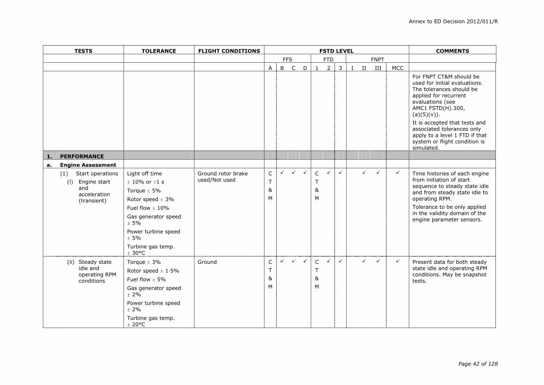
Annex to ED Decision 2012/011/R
Page 42 of 128
TESTS TOLERANCE FLIGHT CONDITIONS FSTD LEVEL COMMENTS
FFS FTD FNPT
A B C D 1 2 3 I II III MCC
For FNPT CT&M should be used for initial evaluations. The tolerances should be applied for recurrent evaluations (see AMC1 FSTD(H).300, (a)(5)(v)).
It is accepted that tests and associated tolerances only apply to a level 1 FTD if that system or flight condition is simulated.
1. PERFORMANCE
a. Engine Assessment
(1) Start operations
(i) Engine start and acceleration (transient)
Light off time
± 10% or ±1 s
Torque ± 5%
Rotor speed ± 3%
Fuel flow ± 10%
Gas generator speed
± 5%
Power turbine speed
± 5%
Turbine gas temp.
± 30°C
Ground rotor brake used/Not used
C
T
&
M
C
T
&
M
Time histories of each engine from initiation of start sequence to steady state idle and from steady state idle to operating RPM.
Tolerance to be only applied in the validity domain of the engine parameter sensors.
(ii) Steady state idle and operating RPM conditions
Torque ± 3%
Rotor speed ± 1·5%
Fuel flow ± 5%
Gas generator speed
± 2%
Power turbine speed
± 2%
Turbine gas temp.
± 20°C
Ground C
T
&
M
C
T
&
M
Present data for both steady state idle and operating RPM conditions. May be snapshot tests.

Annex to ED Decision 2012/011/R
Page 43 of 128
TESTS TOLERANCE FLIGHT CONDITIONS FSTD LEVEL COMMENTS
FFS FTD FNPT
A B C D 1 2 3 I II III MCC
(2) Power turbine speed trim
± 10% of total change
of power turbine speed
or
± 0·5% rotor speed
Ground C
T
&
M
C
T
&
M
Time history of engine response to trim system actuation (both directions).
(3) Engine & rotor
speed governing
Torque ± 5%
Rotor speed ± 1·5%
Climb and descent C
T
&
M
C
T
&
M
Collective step inputs. Can be
conducted with climb & descent performance tests.
b. Ground Operations
(1) Minimum radius turn
Helicopter turn radius ± 3 ft (0·9 m) or 20%
Ground If differential braking is used, brake force should be set at the helicopter test flight value.
(2) Rate of turn vs pedal deflection or nosewheel angle
Turn rate (left and right)
± 10% or 2o /s
Ground Without usage of wheel brakes.
(3) Taxi
Pitch angle ± 1·5o
Torque ± 3%
Longitudinal control
position ± 5%
Lateral control position ± 5%
Directional control position ± 5%
Collective control position ± 5%
Ground C
T
&
M
Control position & pitch angle during ground taxi for a specific ground speed &
direction, and density altitude.
(4) Brake effectiveness
Time : ± 10%or ±1 s
and
Distance : ± 10%or ± 30 m (100 ft)
Ground C
T
&
M
C
T
&
M
C
T
&
M
Record data until full stop.
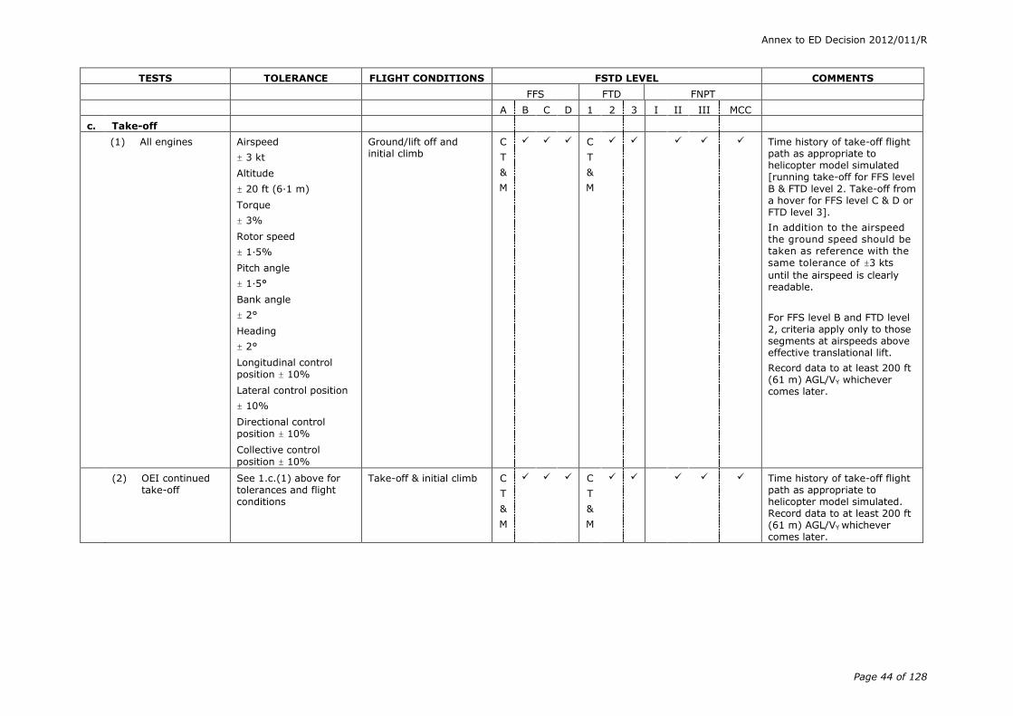
Annex to ED Decision 2012/011/R
Page 44 of 128
TESTS TOLERANCE FLIGHT CONDITIONS FSTD LEVEL COMMENTS
FFS FTD FNPT
A B C D 1 2 3 I II III MCC
c. Take-off
(1) All engines Airspeed
± 3 kt
Altitude
± 20 ft (6·1 m)
Torque
± 3%
Rotor speed
± 1·5%
Pitch angle
± 1·5°
Bank angle
± 2°
Heading
± 2°
Longitudinal control
position ± 10%
Lateral control position
± 10%
Directional control
position ± 10%
Collective control
position ± 10%
Ground/lift off and initial climb
C
T
&
M
C
T
&
M
Time history of take-off flight path as appropriate to helicopter model simulated [running take-off for FFS level
B & FTD level 2. Take-off from a hover for FFS level C & D or FTD level 3].
In addition to the airspeed the ground speed should be taken as reference with the
same tolerance of ±3 kts
until the airspeed is clearly readable.
For FFS level B and FTD level 2, criteria apply only to those segments at airspeeds above effective translational lift.
Record data to at least 200 ft (61 m) AGL/VY whichever comes later.
(2) OEI continued take-off
See 1.c.(1) above for tolerances and flight conditions
Take-off & initial climb C
T
&
M
C
T
&
M
Time history of take-off flight path as appropriate to helicopter model simulated. Record data to at least 200 ft (61 m) AGL/VY whichever comes later.

Annex to ED Decision 2012/011/R
Page 45 of 128
TESTS TOLERANCE FLIGHT CONDITIONS FSTD LEVEL COMMENTS
FFS FTD FNPT
A B C D 1 2 3 I II III MCC
(3) OEI rejected take-off
Airspeed ± 3 kt
Altitude ± 20 ft (6·1 m)
Torque ± 3%
Rotor speed ± 1·5%
Pitch angle ± 1·5°
Bank angle ± 1·5°
Heading ± 2°
Longitudinal control
position ± 10%
Lateral control position
± 10%
Directional control
position ± 10%
Collective control
position ± 10%
Distance: ± 7·5% or
± 30 m (100 ft)
Ground/take-off C
T
&
M
C
T
&
M
Time history from the take-off point to touch down. Test conditions near limiting performance as per aircraft manual.
In addition to the airspeed the ground speed should be taken as reference with the same
tolerance of ± 3 kts until the
airspeed is clearly readable.
d. Hover Performance Torque ± 3%
Pitch angle ± 1·5°
Bank angle ± 1·5°
Longitudinal control
position ± 5%
Lateral control position
± 5%
Directional control
position ± 5%
Collective control
position ± 5%
In ground effect (IGE)
Out of ground effect (OGE)
Stability augmentation on or off
C
T
&
M
C
T
&
M
Light and heavy gross weights. May be snapshot tests.
Refer to point (b)(4)(ii) below for additional guidance.
e. Vertical Climb Performance
Vertical velocity ± 100
fpm (0.50 m/s) or 10%
Directional control
position ± 5%
Collective control
position ± 5%
From OGE hover
Stability augmentation on or off
C
T
&
M
C
T
&
M
Light and heavy gross weights. May be snapshot tests.
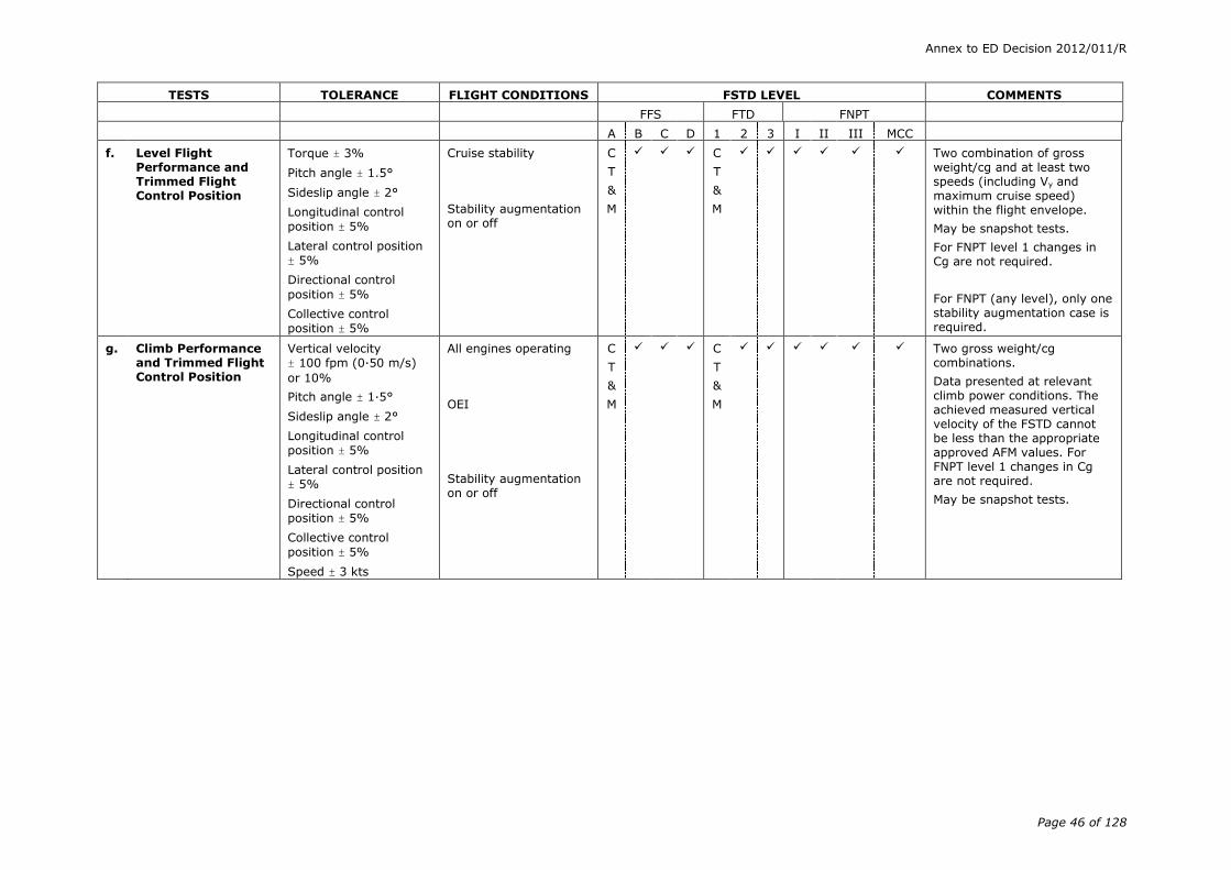
Annex to ED Decision 2012/011/R
Page 46 of 128
TESTS TOLERANCE FLIGHT CONDITIONS FSTD LEVEL COMMENTS
FFS FTD FNPT
A B C D 1 2 3 I II III MCC
f. Level Flight Performance and Trimmed Flight Control Position
Torque ± 3%
Pitch angle ± 1.5°
Sideslip angle ± 2°
Longitudinal control
position ± 5%
Lateral control position
± 5%
Directional control
position ± 5%
Collective control
position ± 5%
Cruise stability
Stability augmentation on or off
C
T
&
M
C
T
&
M
Two combination of gross weight/cg and at least two speeds (including Vy and maximum cruise speed) within the flight envelope.
May be snapshot tests.
For FNPT level 1 changes in Cg are not required.
For FNPT (any level), only one stability augmentation case is required.
g. Climb Performance and Trimmed Flight Control Position
Vertical velocity
± 100 fpm (0·50 m/s)
or 10%
Pitch angle ± 1·5°
Sideslip angle ± 2°
Longitudinal control
position ± 5%
Lateral control position
± 5%
Directional control
position ± 5%
Collective control
position ± 5%
Speed ± 3 kts
All engines operating
OEI
Stability augmentation on or off
C
T
&
M
C
T
&
M
Two gross weight/cg combinations.
Data presented at relevant climb power conditions. The achieved measured vertical velocity of the FSTD cannot be less than the appropriate approved AFM values. For FNPT level 1 changes in Cg are not required.
May be snapshot tests.

Annex to ED Decision 2012/011/R
Page 47 of 128
TESTS TOLERANCE FLIGHT CONDITIONS FSTD LEVEL COMMENTS
FFS FTD FNPT
A B C D 1 2 3 I II III MCC
h. Descent
(1) Descent performance and trimmed flight control
position
Torque ± 3%
Pitch angle ± 1.5°
Sideslip angle ± 2°
Longitudinal Control
Position ± 5%
Lateral Control Position
± 5%
Directional Control
Position ± 5%
Collective Control
Position ± 5%
At or near 1 000 fpm (5 m/s) rate of descent (R/D) at normal approach speed.
Stability augmentation on or off
C
T
&
M
C
T
&
M
Two gross weight/CG combinations.
For FNPT level 1 changes in CG are not required.
May be snapshot tests.
(2) Autorotation performance and trimmed flight control position
Vertical velocity
± 100 fpm (0·50 m/s)
or 10%
Rotor speed ± 1·5%
Pitch angle ± 1·5°
Sideslip angle ± 2°
Longitudinal control
position ± 5%
Lateral control position
± 5%
Directional control
position ± 5%
Collective control
position ± 5%
Steady descents
Stability augmentation on or off
C
T
&
M
Two gross weight/CG combinations.
Rotor speed tolerance only applies if collective control position is fully down.
Speed sweep from approximately 50 kts to at least maximum glide distance airspeed. May be a series of snapshot tests.
i. Auto-rotational Entry
Torque ± 3%
Rotor speed ± 3%
Pitch angle ± 2°
Bank angle ± 3°
Heading ± 5°
Airspeed ± 5 kt
Altitude ± 20 ft (6·1 m)
Cruise or climb C
T
&
M
Time history of vehicle response to a rapid power reduction to idle.
If cruise, data should be presented for the maximum range airspeed. If climb, data should be presented for the maximum rate of climb airspeed at or near maximum continuous power.

Annex to ED Decision 2012/011/R
Page 48 of 128
TESTS TOLERANCE FLIGHT CONDITIONS FSTD LEVEL COMMENTS
FFS FTD FNPT
A B C D 1 2 3 I II III MCC
j. Landing
(1) All engines Airspeed ± 3 kt
Altitude ± 20 ft (6·1 m)
Torque ± 3%
Rotor speed ± 1.5%
Pitch angle ± 1·5°
Bank angle ± 1·5°
Heading ± 2°
Longitudinal control
position ± 10%
Lateral control position
± 10%
Directional control
position ± 10%
Collective control
position ± 10%
Approach and landing C
T
&
M
C
T
&
M
Time history of approach and landing profile as appropriate to helicopter model simulated (running landing for FFS level
B/FTD level 2, approach to a hover and to touch down for FFS level C & D/FTD level 3).
For FFS levels A & B, and FTD levels 1 and 2, & FNPT level II and III criteria apply only to those segments at airspeeds above effective translational lift.
In addition to the airspeed, the ground speed should be taken as reference with the
same tolerance of ± 3 kts at
speeds below which airspeed is not clearly readable.
(2) OEI See 1j(1) above for tolerances
Approach and landing C
T
&
M
C
T
&
M
Include data for both Category A & Category B approaches & landings as appropriate to the helicopter model being simulated.
For FFS levels A & B, and FTD levels 1 and 2, and FNPT level II and III criteria apply to only those segments at airspeeds above effective translational lift.
(3) Balked landing/missed approach
See 1j(1) above for tolerances
Approach, OEI From a stabilised approach at the landing decision point (LDP).

Annex to ED Decision 2012/011/R
Page 49 of 128
TESTS TOLERANCE FLIGHT CONDITIONS FSTD LEVEL COMMENTS
FFS FTD FNPT
A B C D 1 2 3 I II III MCC
(4) Autorotational landing with touch down
Airspeed ± 3 kts
Torque ± 3%
Rotor speed ± 3%
Altitude ± 20 ft (6·1 m)
Pitch angle ± 2°
Bank angle ± 2°
Heading ± 5°
Longitudinal control
position ± 10%
Lateral control position
± 10%
Directional control
position ± 10%
Collective control
position ± 10%
Approach and touch down
C
T
&
M
C
T
&
M
Time history of autorotational deceleration and touch down from a stabilised auto-rotational descent.
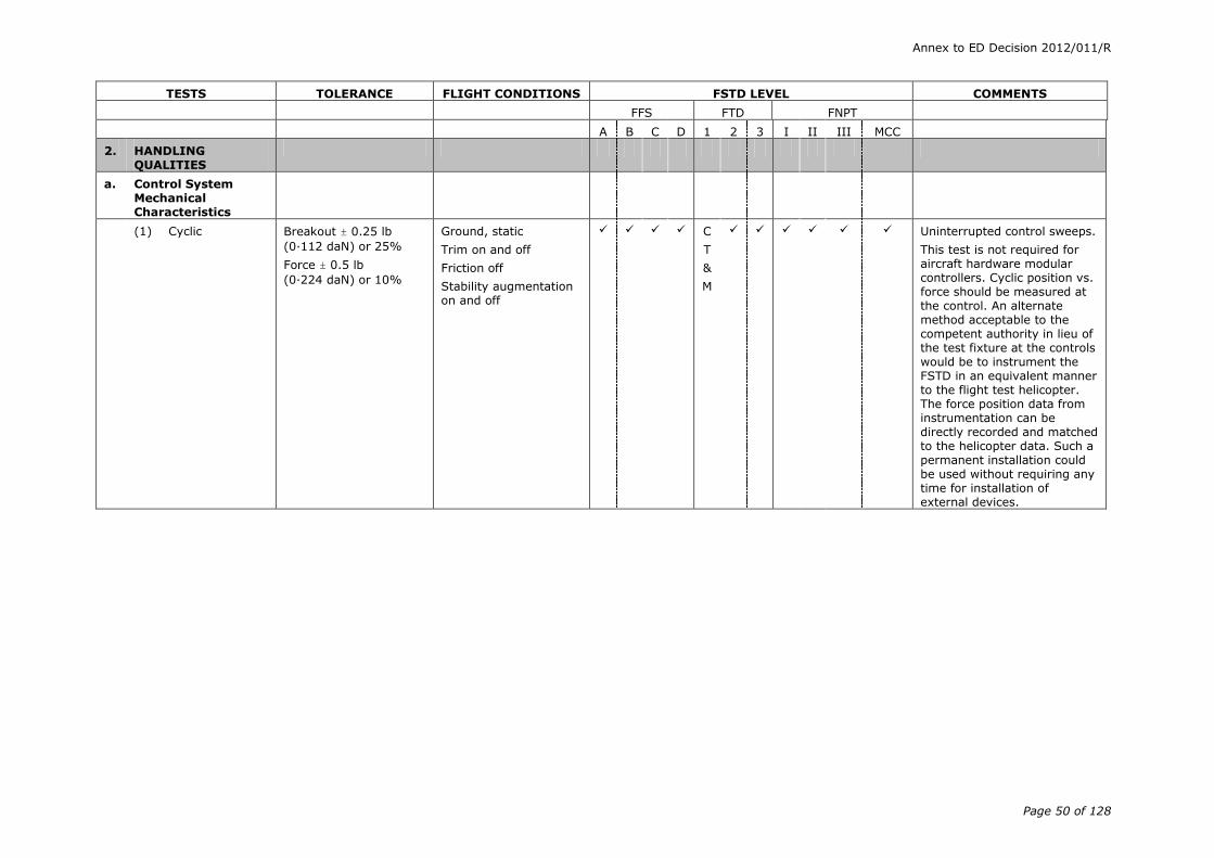
Annex to ED Decision 2012/011/R
Page 50 of 128
TESTS TOLERANCE FLIGHT CONDITIONS FSTD LEVEL COMMENTS
FFS FTD FNPT
A B C D 1 2 3 I II III MCC
2. HANDLING QUALITIES
a. Control System Mechanical Characteristics
(1) Cyclic
Breakout ± 0.25 lb
(0·112 daN) or 25%
Force ± 0.5 lb
(0·224 daN) or 10%
Ground, static
Trim on and off
Friction off
Stability augmentation on and off
C
T
&
M
Uninterrupted control sweeps.
This test is not required for aircraft hardware modular controllers. Cyclic position vs. force should be measured at the control. An alternate method acceptable to the competent authority in lieu of the test fixture at the controls would be to instrument the FSTD in an equivalent manner to the flight test helicopter. The force position data from instrumentation can be directly recorded and matched to the helicopter data. Such a permanent installation could be used without requiring any time for installation of external devices.

Annex to ED Decision 2012/011/R
Page 51 of 128
TESTS TOLERANCE FLIGHT CONDITIONS FSTD LEVEL COMMENTS
FFS FTD FNPT
A B C D 1 2 3 I II III MCC
(2) Collective/ Pedals
Breakout ± 0.5 lb
(0·224 daN) or 10%
Force ± 1.0 lb
(0·448 daN) or 10%
Ground, static
Trim on and off
Friction off
Stability augmentation on/off
C
T
&
M
Uninterrupted control sweeps.
This test is not required for aircraft hardware modular controllers. Collective and pedal position vs. force should be measured at the control. An alternate method acceptable to the competent authority in lieu of the test fixture at the controls would be to instrument the FSTD in an equivalent manner to the flight test helicopter. The
force position data from instrumentation can be directly recorded and matched to the helicopter data. Such a permanent installation could be used without requiring any time for installation of external devices.
(3) Brake pedal force vs. position
± 5 lb (2·224 daN)
or 10%
Ground, static C
T
&
M
C
T
&
M
Simulator computer output results may be used to show compliance.
(4) Trim system rate (all applicable axes)
Rate ± 10% Ground, static
Trim on
Friction off
C
T
&
M
Tolerance applies to recorded value of trim rate.
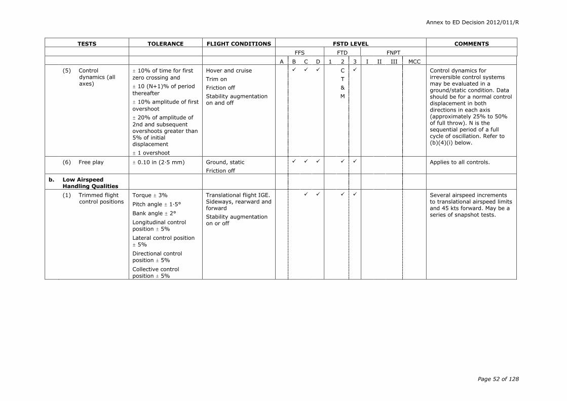
Annex to ED Decision 2012/011/R
Page 52 of 128
TESTS TOLERANCE FLIGHT CONDITIONS FSTD LEVEL COMMENTS
FFS FTD FNPT
A B C D 1 2 3 I II III MCC
(5) Control dynamics (all axes)
± 10% of time for first
zero crossing and
± 10 (N+1)% of period
thereafter
± 10% amplitude of first
overshoot
± 20% of amplitude of
2nd and subsequent overshoots greater than
5% of initial displacement
± 1 overshoot
Hover and cruise
Trim on
Friction off
Stability augmentation on and off
C
T
&
M
Control dynamics for irreversible control systems may be evaluated in a ground/static condition. Data should be for a normal control displacement in both directions in each axis (approximately 25% to 50% of full throw). N is the sequential period of a full cycle of oscillation. Refer to (b)(4)(i) below.
(6) Free play
± 0.10 in (2·5 mm) Ground, static
Friction off
Applies to all controls.
b. Low Airspeed Handling Qualities
(1) Trimmed flight control positions
Torque ± 3%
Pitch angle ± 1·5°
Bank angle ± 2°
Longitudinal control
position ± 5%
Lateral control position
± 5%
Directional control
position ± 5%
Collective control
position ± 5%
Translational flight IGE. Sideways, rearward and forward
Stability augmentation on or off
Several airspeed increments to translational airspeed limits and 45 kts forward. May be a series of snapshot tests.
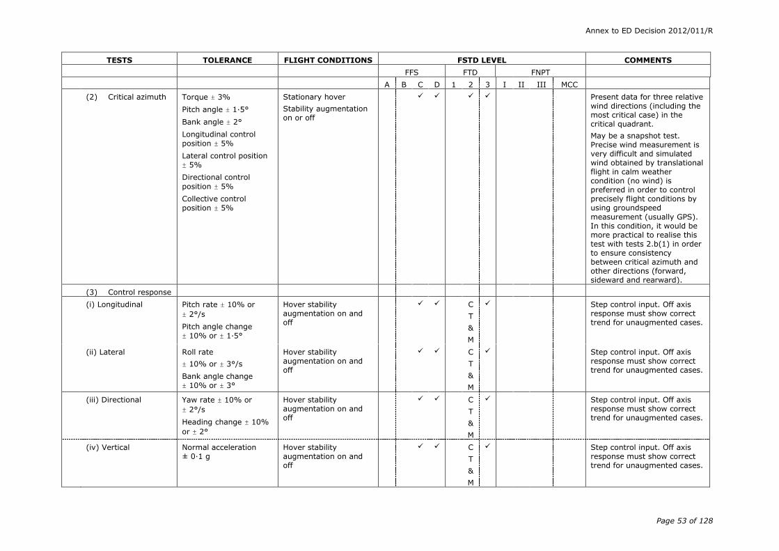
Annex to ED Decision 2012/011/R
Page 53 of 128
TESTS TOLERANCE FLIGHT CONDITIONS FSTD LEVEL COMMENTS
FFS FTD FNPT
A B C D 1 2 3 I II III MCC
(2) Critical azimuth Torque ± 3%
Pitch angle ± 1·5°
Bank angle ± 2°
Longitudinal control
position ± 5%
Lateral control position
± 5%
Directional control
position ± 5%
Collective control
position ± 5%
Stationary hover
Stability augmentation on or off
Present data for three relative wind directions (including the most critical case) in the critical quadrant.
May be a snapshot test. Precise wind measurement is very difficult and simulated wind obtained by translational flight in calm weather condition (no wind) is preferred in order to control precisely flight conditions by using groundspeed
measurement (usually GPS). In this condition, it would be more practical to realise this test with tests 2.b(1) in order to ensure consistency between critical azimuth and other directions (forward, sideward and rearward).
(3) Control response
(i) Longitudinal Pitch rate ± 10% or
± 2°/s
Pitch angle change
± 10% or ± 1·5°
Hover stability augmentation on and off
C
T
&
M
Step control input. Off axis response must show correct trend for unaugmented cases.
(ii) Lateral Roll rate
± 10% or ± 3°/s
Bank angle change
± 10% or ± 3°
Hover stability augmentation on and off
C
T
&
M
Step control input. Off axis response must show correct trend for unaugmented cases.
(iii) Directional Yaw rate ± 10% or
± 2°/s
Heading change ± 10%
or ± 2°
Hover stability augmentation on and off
C
T
&
M
Step control input. Off axis response must show correct trend for unaugmented cases.
(iv) Vertical Normal acceleration ± 0·1 g
Hover stability augmentation on and off
C
T
&
M
Step control input. Off axis response must show correct trend for unaugmented cases.
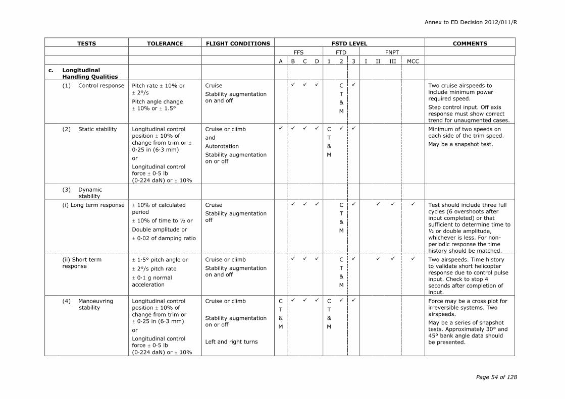
Annex to ED Decision 2012/011/R
Page 54 of 128
TESTS TOLERANCE FLIGHT CONDITIONS FSTD LEVEL COMMENTS
FFS FTD FNPT
A B C D 1 2 3 I II III MCC
c. Longitudinal Handling Qualities
(1) Control response Pitch rate ± 10% or
± 2°/s
Pitch angle change
± 10% or ± 1.5°
Cruise
Stability augmentation on and off
C
T
&
M
Two cruise airspeeds to include minimum power required speed.
Step control input. Off axis response must show correct trend for unaugmented cases.
(2) Static stability Longitudinal control
position ± 10% of
change from trim or ±
0·25 in (6·3 mm)
or
Longitudinal control
force ± 0·5 lb
(0·224 daN) or ± 10%
Cruise or climb
and
Autorotation
Stability augmentation on or off
C
T
&
M
Minimum of two speeds on each side of the trim speed.
May be a snapshot test.
(3) Dynamic stability
(i) Long term response ± 10% of calculated
period
± 10% of time to ½ or
Double amplitude or
± 0·02 of damping ratio
Cruise
Stability augmentation off
C
T
&
M
Test should include three full cycles (6 overshoots after input completed) or that sufficient to determine time to ½ or double amplitude, whichever is less. For non-
periodic response the time history should be matched.
(ii) Short term response
± 1·5° pitch angle or
± 2°/s pitch rate
± 0·1 g normal
acceleration
Cruise or climb
Stability augmentation on and off
C
T
&
M
Two airspeeds. Time history to validate short helicopter response due to control pulse input. Check to stop 4 seconds after completion of input.
(4) Manoeuvring stability
Longitudinal control
position ± 10% of
change from trim or
± 0·25 in (6·3 mm)
or
Longitudinal control
force ± 0·5 lb
(0·224 daN) or ± 10%
Cruise or climb
Stability augmentation on or off
Left and right turns
C
T
&
M
C
T
&
M
Force may be a cross plot for irreversible systems. Two airspeeds.
May be a series of snapshot tests. Approximately 30° and 45° bank angle data should be presented.

Annex to ED Decision 2012/011/R
Page 55 of 128
TESTS TOLERANCE FLIGHT CONDITIONS FSTD LEVEL COMMENTS
FFS FTD FNPT
A B C D 1 2 3 I II III MCC
(5) Landing gear operating time
± 1 s Take-off (retraction)
Approach (extension)
d. Lateral & Directional Handling Qualities.
(1) Control response
(i) Lateral
Roll rate ± 10% or
± 3°/s
Bank angle change
± 10% or ± 3°
Cruise stability augmentation on and off
C
T
&
M
Two airspeeds to include one at or near the minimum power required speed. Step control input. Off axis response must show correct trend for unaugmented cases.
(ii) Directional
Yaw rate ± 10% or 20
/s. Yaw angle change ± 10% or ± 20
Cruise stability augmentation on and off
C
T
&
M
Two airspeeds to include one at or near the minimum power required speed. Step control input. Off axis response must show correct trend for unaugmented cases.
(2) Directional static stability
Lateral control position
± 10% of change from
trim or ± 0·25 in
(6·3 mm) , or lateral
control force ± 0·5 lb
(0·224 daN) or ± 10%
Bank angle ± 1.5°
Directional control
position ± 10% of
change from trim or
± 0.25 in (6·3 mm) or
directional control force
± 1 lb (0·448 daN) or
± 10%
Longitudinal control
position ± 10% of
change from trim or ± 0·25 in (6·3 mm)
Cruise
or
Climb and descent
Stability augmentation on or off
C
T
&
M
C
T
&
M
Steady heading sideslip. Minimum of two sideslip angles on either side of the trim point. Force may be a cross plot for irreversible control systems. May be a snapshot test.

Annex to ED Decision 2012/011/R
Page 56 of 128
TESTS TOLERANCE FLIGHT CONDITIONS FSTD LEVEL COMMENTS
FFS FTD FNPT
A B C D 1 2 3 I II III MCC
(3) Dynamic lateral and directional stability
(i) Lateral-directional oscillations
± 0·5 s or ± 10% of
period
± 10% of time to ½ or
double amplitude or
± 0.02 of damping ratio
± 20% or ± 1 s of Time
difference between peaks of bank and sideslip
Cruise or climb
Stability augmentation
on and off
C
T
&
M
C
T
&
M
C
T
&
M
Two airspeeds. Excite with cyclic or pedal doublet. Test
should include six full cycles (12 overshoots after input completed) or that sufficient to determine time to ½ or double amplitude, whichever is less. For non-periodic response, time history should be matched.
(ii) Spiral stability Correct trend on bank -
± 2° or ± 10% in 20 s
Cruise or climb
Stability augmentation on and off
C
T
&
M
C
T
&
M
C
T
&
M
Time history of release from pedal only or cyclic only turns in both directions. Terminate check at zero bank or unsafe attitude for divergent cases.
(iii) Adverse/ proverse yaw
Correct trend on side slip
± 2°
Cruise or climb
Stability augmentation on and off
C
T
&
M
C
T
&
M
Time history of initial entry into cyclic only turns in both directions. Use moderate cyclic input rate.
3. ATMOSPHERIC MODELS
(1) A test to demonstrate turbulence models
N/A Take-off, cruise and landing
(2) Tests to demonstrate other atmospheric models to support the required training

Annex to ED Decision 2012/011/R
Page 57 of 128
TESTS TOLERANCE FLIGHT CONDITIONS FSTD LEVEL COMMENTS
FFS FTD FNPT
A B C D 1 2 3 I II III MCC
4. MOTION SYSTEM **
a. Motion Envelope
(1) Pitch N/A
(i) Displacement
± 200
± 250
(ii) Velocity
± 150/s
± 20o/s
(iii) Acceleration
± 75o/s²
± 100o/s²
(2) Roll N/A
(i) Displacement
± 200
± 250
(ii) Velocity
± 150/s
± 20o/s
(iii) Acceleration
± 75o/s
± 100o/s
(3) Yaw N/A
(i) Displacement
± 250
(ii) Velocity
± 150/s
± 20o/s
(iii) Acceleration
± 75o/s²
± 100o/s²
** For Level A, if more than the three specified degrees of freedom (DOF) are used, then the corresponding Level B performance standards should be used.
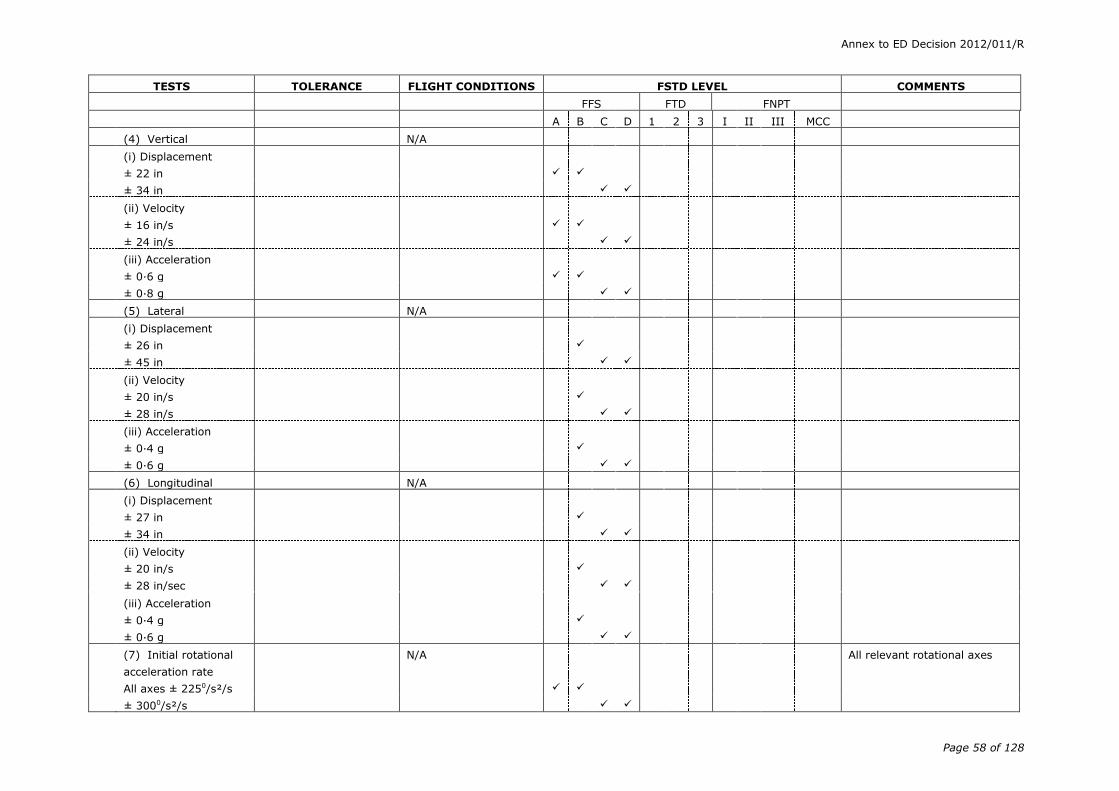
Annex to ED Decision 2012/011/R
Page 58 of 128
TESTS TOLERANCE FLIGHT CONDITIONS FSTD LEVEL COMMENTS
FFS FTD FNPT
A B C D 1 2 3 I II III MCC
(4) Vertical N/A
(i) Displacement
± 22 in
± 34 in
(ii) Velocity
± 16 in/s
± 24 in/s
(iii) Acceleration
± 0·6 g
± 0·8 g
(5) Lateral N/A
(i) Displacement
± 26 in
± 45 in
(ii) Velocity
± 20 in/s
± 28 in/s
(iii) Acceleration
± 0·4 g
± 0·6 g
(6) Longitudinal N/A
(i) Displacement
± 27 in
± 34 in
(ii) Velocity
± 20 in/s
± 28 in/sec
(iii) Acceleration
± 0·4 g
± 0·6 g
(7) Initial rotational
acceleration rate
All axes ± 2250/s²/s
N/A
All relevant rotational axes
± 3000/s²/s
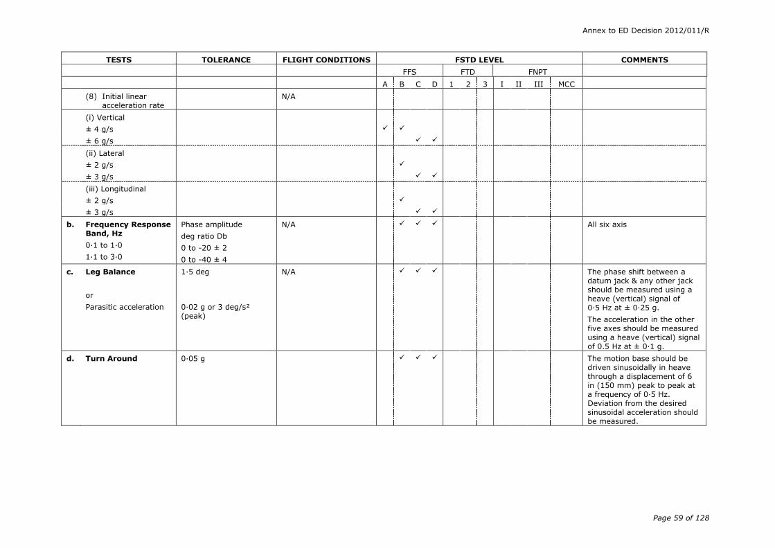
Annex to ED Decision 2012/011/R
Page 59 of 128
TESTS TOLERANCE FLIGHT CONDITIONS FSTD LEVEL COMMENTS
FFS FTD FNPT
A B C D 1 2 3 I II III MCC
(8) Initial linear acceleration rate
N/A
(i) Vertical
± 4 g/s
± 6 g/s
(ii) Lateral
± 2 g/s
± 3 g/s
(iii) Longitudinal
± 2 g/s
± 3 g/s
b. Frequency Response Band, Hz
0·1 to 1·0
1·1 to 3·0
Phase amplitude
deg ratio Db
0 to -20 ± 2
0 to -40 ± 4
N/A All six axis
c. Leg Balance
or
Parasitic acceleration
1·5 deg
0·02 g or 3 deg/s² (peak)
N/A The phase shift between a datum jack & any other jack should be measured using a heave (vertical) signal of 0·5 Hz at ± 0·25 g.
The acceleration in the other five axes should be measured using a heave (vertical) signal of 0.5 Hz at ± 0·1 g.
d. Turn Around 0·05 g The motion base should be driven sinusoidally in heave through a displacement of 6 in (150 mm) peak to peak at a frequency of 0·5 Hz. Deviation from the desired sinusoidal acceleration should be measured.

Annex to ED Decision 2012/011/R
Page 60 of 128
TESTS TOLERANCE FLIGHT CONDITIONS FSTD LEVEL COMMENTS
FFS FTD FNPT
A B C D 1 2 3 I II III MCC
e. Characteristic vibrations/buffet
(1) Vibrations - tests to include 1/rev and n/rev vibrations where n is the number of rotor blades
+ 3 / - 6 db or ± 10% of nominal vibration level in flight cruise & correct trend (see comment)
On ground (idle flt nr); low & high speed;
Level flight;
Climb/descent (including vertical climb;
Autorotation;
Steady turns)
Refer to book 1, Appendix 1 to CS-FSTD(H).300 paragraph 1.2.e.1.
Correct trend refers to a comparison of vibration amplitudes between different manoeuvres. E.g. If the 1/rev vibration amplitude in the helicopter is higher during steady state turns than in level flight this increasing trend should be demonstrated in the FFS.
(2) Buffet
A test with recorded results is required for characteristic buffet motion which can be sensed in the cockpit
+ 3 / - 6 db or ± 10% of nominal vibration level in flight cruise & correct trend (see comment)
On ground and in flight
Refer to section 1, Appendix 1 to CS-FSTD(H).300 paragraph 1.2.e.1.
The recorded test results for characteristic buffets should allow the checking of relative amplitude for different frequencies.
For atmospheric disturbance, general purpose models are acceptable which approximate demonstrable flight test data.
f. Motion Cue Repeatability
N/A See para (b)(4)(iii)(C) below.

Annex to ED Decision 2012/011/R
Page 61 of 128
TESTS TOLERANCE FLIGHT CONDITIONS FSTD LEVEL COMMENTS
FFS FTD FNPT
A B C D 1 2 3 I II III MCC
5. VISUAL SYSTEM
Note: refer to the table of functions & subjective tests for additional visual tests.
a. Visual ground segment (VGS)
Near end. The lights computed to be visible should be visible in the FSTD.
Far end : ± 20% of the
computed VGS
Trimmed in landing configuration at 100 ft landing gear height above touch down zone on glide slope with 300 m or 350 m RVR
Visual ground segment. This test is designed to assess items impacting the accuracy of the visual scene presented to a pilot at DH on an ILS approach. Those items include:
1) RVR;
2) glideslope (G/S) and localiser modelling accuracy (location and slope) for an ILS;
3) for a given weight, configuration and speed representative of a point within the helicopter’s operational envelope for a normal approach and landing.
Visual ground segment (VGS)
(continued)
Trimmed in landing configuration at 200 ft landing gear height above touch down zone on glide slope with 500 m RVR
If non-homogenous fog is used, the vertical variation in horizontal visibility should be described and be included in the slant range visibility calculation used in the VGS computation.
The downward field of view may be limited by the aircraft structure or the visual system display, whichever is less.
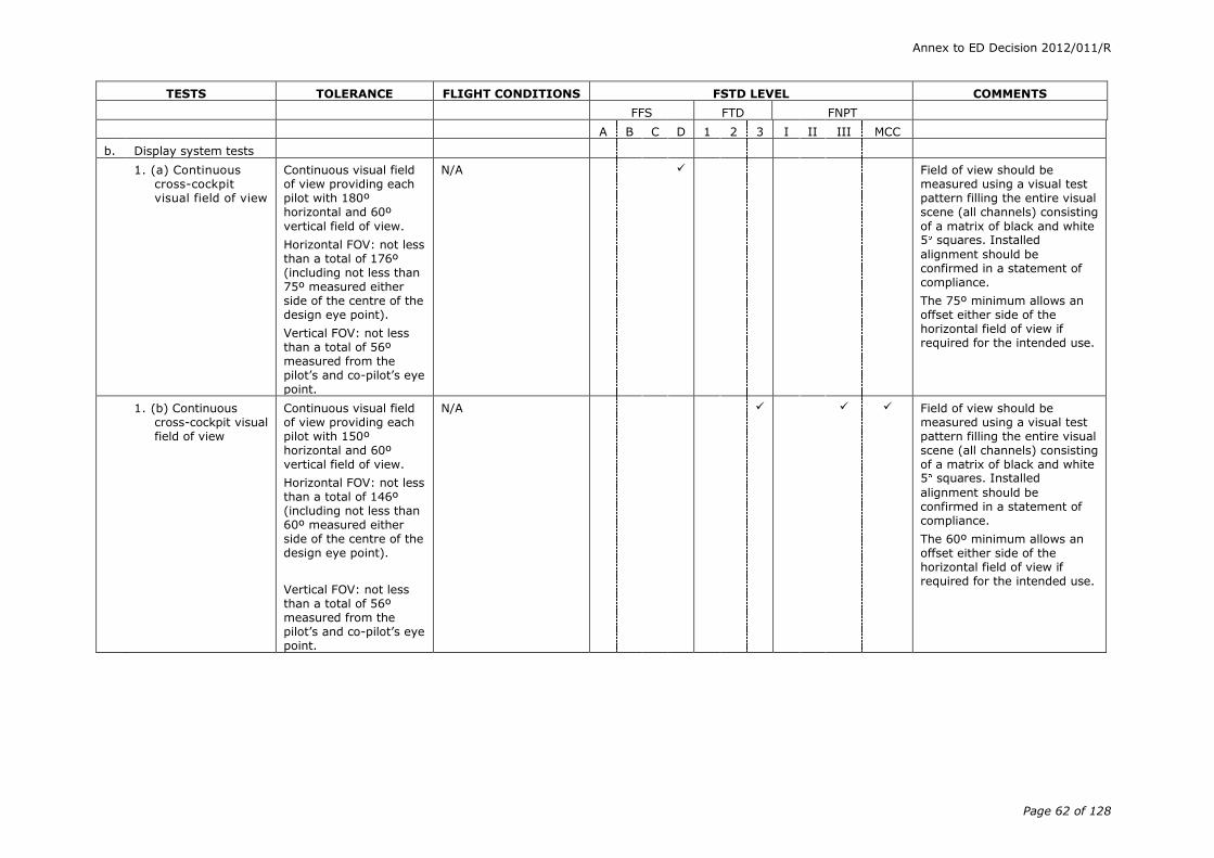
Annex to ED Decision 2012/011/R
Page 62 of 128
TESTS TOLERANCE FLIGHT CONDITIONS FSTD LEVEL COMMENTS
FFS FTD FNPT
A B C D 1 2 3 I II III MCC
b. Display system tests
1. (a) Continuous cross-cockpit visual field of view
Continuous visual field of view providing each pilot with 180º horizontal and 60º
vertical field of view.
Horizontal FOV: not less than a total of 176º (including not less than 75º measured either side of the centre of the design eye point).
Vertical FOV: not less than a total of 56º measured from the pilot’s and co-pilot’s eye point.
N/A Field of view should be measured using a visual test pattern filling the entire visual scene (all channels) consisting
of a matrix of black and white 5 squares. Installed
alignment should be confirmed in a statement of compliance.
The 75º minimum allows an offset either side of the horizontal field of view if required for the intended use.
1. (b) Continuous cross-cockpit visual field of view
Continuous visual field of view providing each pilot with 150º horizontal and 60º vertical field of view.
Horizontal FOV: not less than a total of 146º (including not less than 60º measured either side of the centre of the design eye point).
Vertical FOV: not less than a total of 56º measured from the pilot’s and co-pilot’s eye point.
N/A Field of view should be measured using a visual test pattern filling the entire visual scene (all channels) consisting of a matrix of black and white 5 squares. Installed
alignment should be confirmed in a statement of compliance.
The 60º minimum allows an offset either side of the horizontal field of view if required for the intended use.

Annex to ED Decision 2012/011/R
Page 63 of 128
TESTS TOLERANCE FLIGHT CONDITIONS FSTD LEVEL COMMENTS
FFS FTD FNPT
A B C D 1 2 3 I II III MCC
1. (c) Continuous cross-cockpit visual field of view
Continuous visual field of view providing each pilot with 150º horizontal and 40º vertical field of view.
Horizontal FOV: not less than a total of 146º (including not less than 60º measured either side of the centre of the design eye point).
Vertical FOV: not less than a total of 36 º
measured from the pilot’s and co-pilot’s eye point.
N/A Field of view should be measured using a visual test pattern filling the entire visual scene (all channels) consisting of a matrix of black and white 5 squares. Installed
alignment should be confirmed in a statement of compliance.
The 60º minimum allows an offset either side of the horizontal field of view if required for the intended use.
1. (d) Visual field of view
Visual system providing each pilot with 75º horizontal and 40º vertical field of view
N/A
Visual system providing each pilot with 45º horizontal and 30º vertical field of view
2. Occulting demonstrate 10 levels of occulting through each channel of the system
Demonstration model N/A
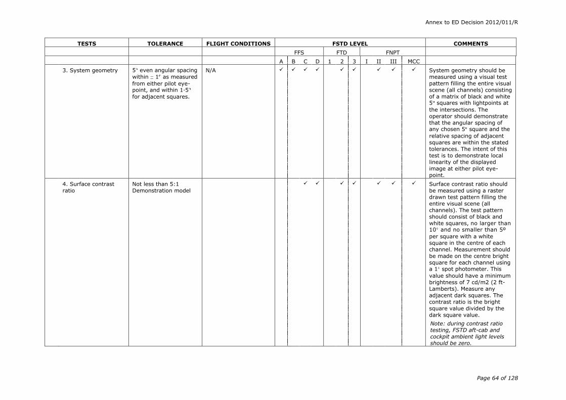
Annex to ED Decision 2012/011/R
Page 64 of 128
TESTS TOLERANCE FLIGHT CONDITIONS FSTD LEVEL COMMENTS
FFS FTD FNPT
A B C D 1 2 3 I II III MCC
3. System geometry 5 even angular spacing
within 1 as measured
from either pilot eye-point, and within 1·5
for adjacent squares.
N/A System geometry should be measured using a visual test pattern filling the entire visual scene (all channels) consisting of a matrix of black and white 5 squares with lightpoints at
the intersections. The operator should demonstrate that the angular spacing of any chosen 5 square and the
relative spacing of adjacent squares are within the stated tolerances. The intent of this test is to demonstrate local linearity of the displayed image at either pilot eye-point.
4. Surface contrast ratio
Not less than 5:1 Demonstration model
Surface contrast ratio should be measured using a raster drawn test pattern filling the entire visual scene (all channels). The test pattern should consist of black and white squares, no larger than 10 and no smaller than 5º
per square with a white square in the centre of each channel. Measurement should be made on the centre bright square for each channel using a 1 spot photometer. This
value should have a minimum brightness of 7 cd/m2 (2 ft-Lamberts). Measure any adjacent dark squares. The contrast ratio is the bright square value divided by the dark square value.
Note: during contrast ratio testing, FSTD aft-cab and cockpit ambient light levels should be zero.

Annex to ED Decision 2012/011/R
Page 65 of 128
TESTS TOLERANCE FLIGHT CONDITIONS FSTD LEVEL COMMENTS
FFS FTD FNPT
A B C D 1 2 3 I II III MCC
5. Highlight brightness Not less than 20 cd/m2 (6 ft-Lamberts) from the display measured at the design eye point
N/A
Highlight brightness should be measured by maintaining the full test pattern described in paragraph 5.b.3 above, superimposing a highlight on the centre white square of each channel and measuring the brightness. Lightpoints are not acceptable. Use of calligraphic capabilities to enhance raster brightness is acceptable.
For raster only display devices
the highlight brightness is measured using a white raster and measuring the average brightness in each channel.
Not less than 17 cd/m2 (5 ft-Lamberts) from the display measured at the design eye point
6. Vernier resolution Not greater than 3 arc minutes
N/A Vernier resolution should be demonstrated by a test of objects shown to occupy the required visual angle in each visual display used on a scene from the pilot’s eye-point.
7. Lightpoint size Not greater than 6 arc minutes
N/A Lightpoint size should be measured using a test pattern consisting of a centrally located single row of lightpoints reduced in length until modulation is just discernible in each visual channel.
A row of 40 lights in the case of 6 arc minutes (30 lights in the case of 8 arc minutes) will form a 4 angle or less.
Not greater than 8 arc minutes
Demonstration model
N/A
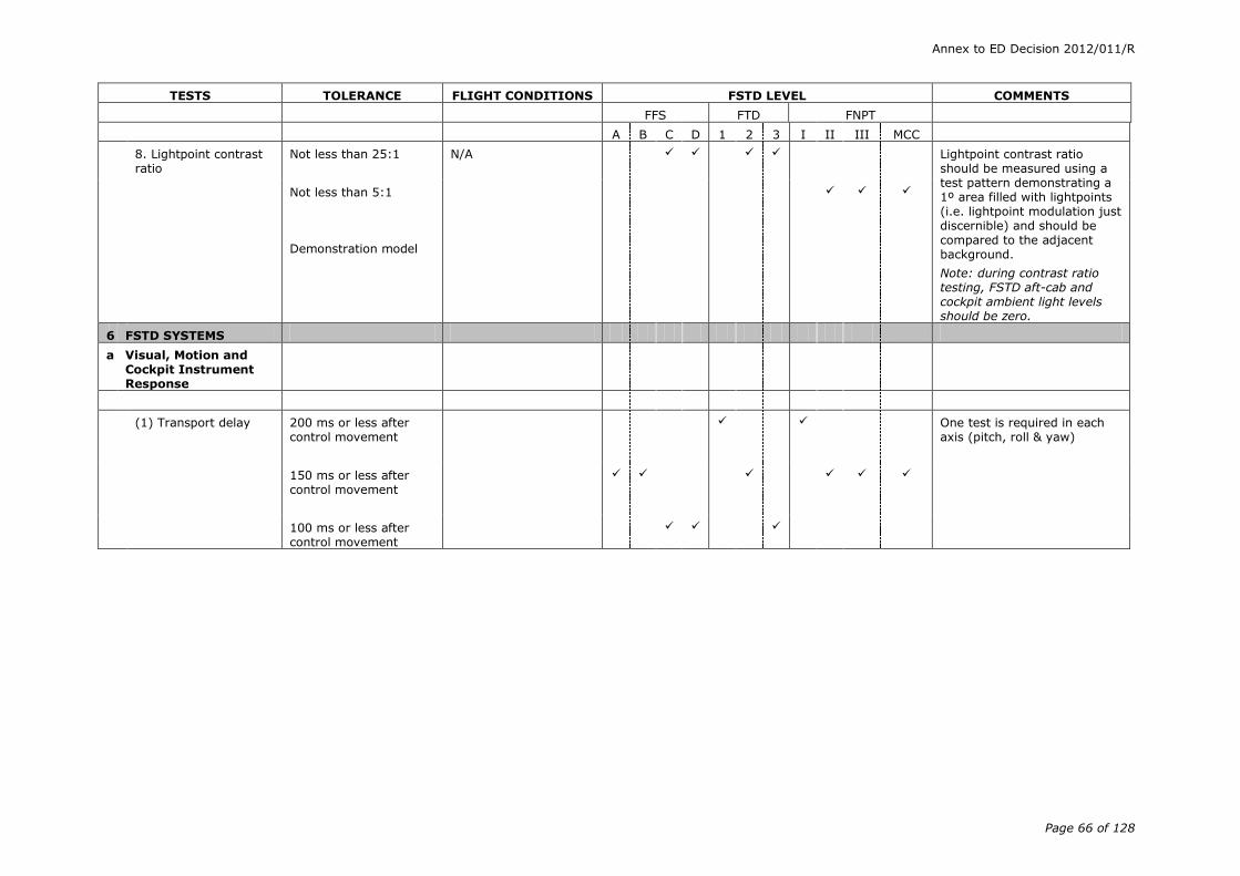
Annex to ED Decision 2012/011/R
Page 66 of 128
TESTS TOLERANCE FLIGHT CONDITIONS FSTD LEVEL COMMENTS
FFS FTD FNPT
A B C D 1 2 3 I II III MCC
8. Lightpoint contrast ratio
Not less than 25:1
N/A Lightpoint contrast ratio should be measured using a test pattern demonstrating a 1º area filled with lightpoints (i.e. lightpoint modulation just discernible) and should be compared to the adjacent background.
Note: during contrast ratio testing, FSTD aft-cab and cockpit ambient light levels should be zero.
Not less than 5:1
Demonstration model
6 FSTD SYSTEMS
a Visual, Motion and Cockpit Instrument Response
(1) Transport delay 200 ms or less after control movement
One test is required in each axis (pitch, roll & yaw)
150 ms or less after control movement
100 ms or less after control movement

Annex to ED Decision 2012/011/R
Page 67 of 128
TESTS TOLERANCE FLIGHT CONDITIONS FSTD LEVEL COMMENTS
FFS FTD FNPT
A B C D 1 2 3 I II III MCC
(1) Transport delay (continued)
This test should measure all the delay encountered by a step signal migrating from the pilot’s control through the control loading electronics and interfacing through all the simulation software modules in the correct order, using a handshaking protocol, finally through the normal output interfaces to the motion system (where applicable), to the visual system and
instrument displays. A recordable start time for the test should be provided by a pilot flight control input. The test mode should permit normal computation time to be consumed and should not alter the flow of information through the hardware/software system. The Transport Delay of the system is then the time between control input and the individual hardware (systems) responses. It need only be measured once in each axis, being independent of flight conditions. Visual change may start before motion response but motion acceleration must occur before completion of visual scan of first video field that contains different information.

Annex to ED Decision 2012/011/R
Page 68 of 128
TESTS TOLERANCE FLIGHT CONDITIONS FSTD LEVEL COMMENTS
FFS FTD FNPT
A B C D 1 2 3 I II III MCC
OR alternative test:
Latency
(2) Visual, motion (where fitted),
instrument system response to an abrupt pilot controller input, compared to helicopter response for a similar input.
150 ms or less after helicopter response’
Climb, cruise and descent
One test is required in each axis (pitch, roll and yaw) for
each of the flight conditions, compared to helicopter data.
Visual change may start before motion response but motion acceleration must occur before completion of visual scan of first video field that contains different information.
Latency (continued) 100 ms or less after helicopter response
Climb, cruise, descent and hover (hover FFS only)
The test to determine compliance should include simultaneously recording the output from the pilot’s cyclic, collective and pedals, the output from an accelerometer attached to the motion system platform located at an acceptable location near the pilot’s seats (where applicable), the output from the visual system display (including visual system delays), and the output signal to the pilot’s attitude indicator or an equivalent test approved by the competent authority. The test results in a comparison of a recording of the simulator's response with actual helicopter data.
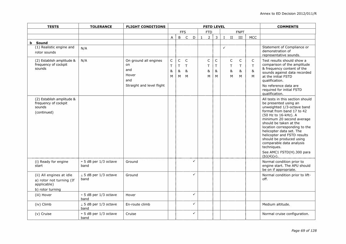
Annex to ED Decision 2012/011/R
Page 69 of 128
TESTS TOLERANCE FLIGHT CONDITIONS FSTD LEVEL COMMENTS
FFS FTD FNPT
A B C D 1 2 3 I II III MCC
b Sound
(1) Realistic engine and
rotor sounds N/A Statement of Compliance or
demonstration of representative sounds.
(2) Establish amplitude & frequency of cockpit sounds
N/A On ground all engines on
and
Hover
and
Straight and level flight
C
T
&
M
C
T
&
M
C
T
&
M
C
T
&
M
C
T
&
M
C
T
&
M
C
T
&
M
C
T
&
M
Test results should show a comparison of the amplitude & frequency content of the sounds against data recorded at the initial FSTD qualification.
No reference data are required for initial FSTD qualification.
(2) Establish amplitude & frequency of cockpit sounds
(continued)
All tests in this section should be presented using an unweighted 1/3-octave band format from band 17 to 42 (50 Hz to 16-kHz). A minimum 20 second average should be taken at the location corresponding to the helicopter data set. The helicopter and FSTD results should be produced using comparable data analysis techniques.
See AMC1 FSTD(H).300 para (b)(4)(v).
(i) Ready for engine start
5 dB per 1/3 octave
band Ground Normal condition prior to
engine start. The APU should be on if appropriate.
(ii) All engines at idle
a) rotor not turning (If applicable)
b) rotor turning
5 dB per 1/3 octave
band Ground Normal condition prior to lift-
off.
(iii) Hover 5 dB per 1/3 octave
band
Hover
(iv) Climb 5 dB per 1/3 octave
band
En-route climb Medium altitude.
(v) Cruise 5 dB per 1/3 octave
band Cruise Normal cruise configuration.

Annex to ED Decision 2012/011/R
Page 70 of 128
TESTS TOLERANCE FLIGHT CONDITIONS FSTD LEVEL COMMENTS
FFS FTD FNPT
A B C D 1 2 3 I II III MCC
(vi) Final approach 5 dB per 1/3 octave
band
Landing Constant airspeed, gear down.
(3) Special cases n/a C
T
&
M
Special cases identified as particularly significant to the pilot, important in training, or unique to a specific helicopter type or variant.
(4) FSTD background noise
Initial evaluation: n/a
Recurrent evaluation: 3 dB per 1/3 octave
band compared to initial evaluation
Results of the background noise at initial qualification should be included in the QTG document and approved by the qualifying authority. The simulated sound should
be evaluated to ensure that the background noise does not interfere with training. Refer to AMC1 FSTD(H).300 para (b)(4)(v)(F). The measurements are to be made with the simulation running, the sound muted and a dead cockpit.
(5) Frequency response Initial evaluation: n/a
Recurrent evaluation: cannot exceed 5 dB
on three consecutive bands when compared to initial evaluation and the average of the absolute differences between initial and recurrent evaluation results cannot exceed 2 dB.
Only required if the results are to be used during recurrent evaluations according to AMC1 FSTD(H).300 para (b)(4)(v)(G). The results should be acknowledged by the competent authority at initial qualification.

Annex to ED Decision 2012/011/R
Page 71 of 128
(4) Information for validation tests
(i) Control dynamics
(A) General
The characteristics of an aircraft flight control system have a major effect on handling qualities. A significant consideration in pilot acceptability of an aircraft is the ‘feel’ provided through the flight controls. Considerable effort is expended on aircraft feel system design so that pilots will be comfortable and will consider the aircraft desirable to fly. In order for an FSTD to be representative, it too should present the pilot with the proper feel – that of the aircraft being simulated. Compliance with this requirement should be determined by comparing a recording of the control feel dynamics of the FSTD to actual aircraft measurements in the relevant configurations.
(a) Recordings such as free response to a pulse or step function are classically used to estimate the dynamic properties of electromechanical systems. In any case, the dynamic properties can only be estimated since the true inputs and responses are also only estimated. Therefore, it is imperative that the best possible data be collected since close matching of the FSTD control loading system to the helicopter systems is essential. The required dynamic control checks are indicated in paragraph (b)(3) – 2.b(1) to (3) of the table of FSTD validation tests.
(b) For initial and upgrade evaluations, control dynamics characteristics should be measured at and recorded directly from the flight controls. This procedure is usually accomplished by measuring the free response of the controls using a step input or pulse input to excite the system. The procedure should be accomplished in relevant flight conditions and configurations.
(c) For helicopters with irreversible control systems, measurements may be obtained on the ground if proper pitot-static inputs (if applicable) are provided to represent airspeeds typical of those encountered in flight. Likewise, it may be shown that for some helicopters, hover, climb, cruise and autorotation may have like effects. Thus, one may suffice for another. If either or both considerations apply, engineering validation or helicopter manufacturer rationale should be submitted as justification for ground tests or for eliminating a configuration. For FSTDs requiring static and dynamic tests at the controls, special test fixtures should not be required during initial and upgrade evaluations if the MQTG shows both test fixture results and the results of an alternate approach, such as computer plots which were produced concurrently and show satisfactory agreement. Repeat of the alternate method during the initial evaluation would then satisfy this test requirement.
(B) Control dynamics evaluation
The dynamic properties of control systems are often stated in terms of frequency, damping, and a number of other classical measurements which can be found in texts on control systems. In order to establish a consistent means of validating test results for FSTD control loading, criteria are needed that clearly define the interpretation of the measurements and the tolerances to be applied. Criteria are needed for underdamped, critically damped, and overdamped systems. In the case of an underdamped system with
Annex to ED Decision 2012/011/R
Page 72 of 128
very light damping, the system may be quantified in terms of frequency and damping. In critically damped or overdamped systems, the frequency and damping are not readily measured from a response time history. Therefore, some other measurement should be used.
Tests to verify that control feel dynamics represent the helicopter should show that the dynamic damping cycles (free response of the controls) match that of the helicopter within specified tolerances. The method of evaluating the response and the tolerance to be applied is described in the underdamped and critically damped cases are as follows:
(a) Underdamped response
(1) Two measurements are required for the period, the time to first zero crossing (in case a rate limit is present) and the subsequent frequency of oscillation. It is necessary to measure cycles on an individual basis in case there are non-uniform periods in the response. Each period should be independently compared with the respective period of the helicopter control system and, consequently, should enjoy the full tolerance specified for that period.
(2) The damping tolerance should be applied to overshoots on an individual basis. Care should be taken when applying the tolerance to small overshoots since the significance of such overshoots becomes questionable. Only those overshoots larger than 5% of the total initial displacement should be considered. The residual band, labelled T(Ad) in Figure 1 is ± 5% of the initial displacement amplitude Ad from the steady state value of the oscillation. Only oscillations outside the residual band are considered significant. When comparing FSTD data to helicopter data, the process should begin by overlaying or aligning the FSTD and helicopter steady state values and then comparing amplitudes of oscillation peaks, the time of the first zero crossing, and individual periods of oscillation. The FSTD should show the same number of significant overshoots to within one when compared against the helicopter data. This procedure for evaluating the response is illustrated in Figure 1 below.
(b) Critically damped and overdamped response. Due to the nature of critically damped and overdamped responses (no overshoots), the time to reach 90% of the steady state (neutral point) value should be the same as the helicopter within ± 10%. Figure 2 illustrates the procedure.
(c) Special considerations. Control systems, which exhibit characteristics other than classical overdamped or underdamped responses should meet specified tolerances. In addition, special consideration should be given to ensure that significant trends are maintained.
(C) Tolerances
The following table summarises the tolerances, T. See figures 1 and 2 for an illustration of the referenced measurements.
T(P0) ± 10% of P0
T(P1) ± 20% of P1
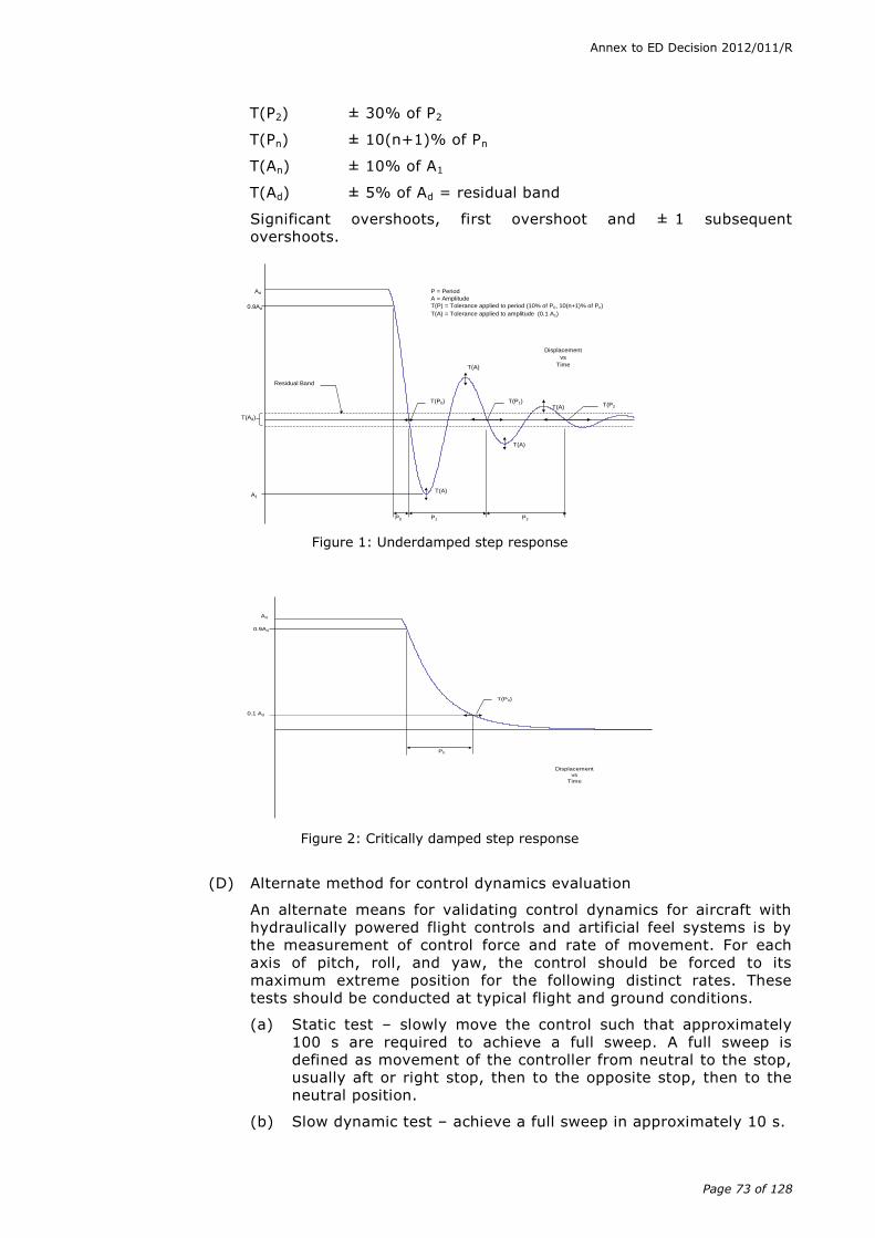
Annex to ED Decision 2012/011/R
Page 73 of 128
T(P2) ± 30% of P2
T(Pn) ± 10(n+1)% of Pn
T(An) ± 10% of A1
T(Ad) ± 5% of Ad = residual band
Significant overshoots, first overshoot and ± 1 subsequent overshoots.
Figure 1: Underdamped step response
Figure 2: Critically damped step response
(D) Alternate method for control dynamics evaluation
An alternate means for validating control dynamics for aircraft with hydraulically powered flight controls and artificial feel systems is by the measurement of control force and rate of movement. For each axis of pitch, roll, and yaw, the control should be forced to its maximum extreme position for the following distinct rates. These tests should be conducted at typical flight and ground conditions.
(a) Static test – slowly move the control such that approximately 100 s are required to achieve a full sweep. A full sweep is defined as movement of the controller from neutral to the stop, usually aft or right stop, then to the opposite stop, then to the neutral position.
(b) Slow dynamic test – achieve a full sweep in approximately 10 s.
P = Period
A = Amplitude
T(P) = Tolerance applied to period (10% of P0, 10(n+1)% of Pn)
T(A) = Tolerance applied to amplitude (0.1 A1)
T(Ad)
Ad
A1
T(A)
P0 P1
T(P0) T(P1)
Displacement
vs
Time
Residual Band
0.9Ad
P2
T(A)
T(A)
T(P2
)T(A)
Ad
P0
Displacement
vs
Time
0.9Ad
0.1 Ad
T(P0)
Annex to ED Decision 2012/011/R
Page 74 of 128
(c) Fast dynamic test – achieve a full sweep in approximately 4 s.
Note: dynamic sweeps may be limited to forces not exceeding 44.5 daN (100 lbs).
(E) Tolerances
(a) Static test, see paragraph (b)(3) – 2.a(1), (2), and (3) of the table of FSTD validation tests.
(b) Dynamic test – ± 0.9 daN (2 lbs) or ± 10% on dynamic increment above static test.
The competent authority is open to alternative means such as the one described above. Such alternatives should, however, be justified and appropriate to the application. For example, the method described here may not apply to all manufacturers’ systems and certainly not to aircraft with reversible control systems. Hence, each case should be considered on its own merit on an ad hoc basis. Should the competent authority find that alternative methods do not result in satisfactory performance, then more conventionally accepted methods should be used.
(ii) Ground effect
(A) For an FSTD to be used for lift-off and touch down it should faithfully reproduce the aerodynamic changes which occur in ground effect. The parameters chosen for FSTD validation should be indicative of these changes. The primary validation parameters for characteristics in ground effect are:
(a) longitudinal, lateral, directional and collective control positions;
(b) torque required for hover;
(c) height;
(d) airspeed;
(e) pitch angle; and
(f) bank angle.
A dedicated test should be provided to validate the aerodynamic ground effect characteristics.
The selection of the test method and procedures to validate ground effect is at the option of the organisation performing the flight tests; however, the flight test should be performed with enough duration near the ground to validate sufficiently the ground-effect model.
(B) Acceptable tests for validation of ground effect include the following:
(a) Level fly-bys: these should be conducted at a minimum of three altitudes within the ground effect, including one at no more than 10% of the rotor diameter above the ground, one each at approximately 30% and 70% of the rotor diameter where height refers to main gear above the ground. In addition, one level-flight trim condition should be conducted out of ground effect, e.g. at 150% of rotor diameter. Level 2/3 FTDs and II/III FNPTs may use methods other than the level fly-by method.
(b) Shallow approach landing: this should be performed at a glideslope of approximately one degree with negligible pilot activity until flare.

Annex to ED Decision 2012/011/R
Page 75 of 128
If other methods are proposed, a rationale should be provided to conclude that the tests performed validate the ground-effect model.
(iii) Motion system
(A) General
Pilots use continuous information signals to regulate the state of the helicopter. In concert with the instruments and outside-world visual information, whole-body motion feedback is essential in assisting the pilot to control the helicopter’s dynamics, particularly in the presence of external disturbances. The motion system should therefore meet basic objective performance criteria, as well as being subjectively tuned at the pilot’s seat position to represent the linear and angular accelerations of the helicopter during a prescribed minimum set of manoeuvres and conditions. Moreover, the response of the motion cueing system should be repeatable.
(B) Motion system checks
The intent of tests as described in the table of FSTD validation tests, paragraph (b)(3) - 4.a: motion envelope, 4.b: frequency response band, 4.c: leg balance and 4.d: turn around, is to demonstrate the performance of the motion system hardware, and to check the integrity of the motion set-up with regard to calibration and wear. These tests are independent of the motion cueing software and should be considered as robotic tests.
(C) Motion cue repeatability testing
The motion system characteristics in the table of validation tests address basic system capability, but not pilot cueing capability. Until there is an objective procedure for determination of the motion cues necessary to support pilot tasks and stimulate the pilot response that occurs in an aircraft for the same tasks, motion systems should continue to be “tuned” subjectively. Having tuned a motion system, however, it is important to demonstrate objectively that the system continues to perform as originally qualified. Any motion performance change from the initially qualified baseline can be measured objectively. An objective assessment of motion performance change should be accomplished at least annually using the following testing procedure:
(a) The current performance of the motion system should be assessed by comparison with the initial recorded data.
(b) The parameters to be recorded should be the motion system drive algorithm acceleration command and the actual acceleration measured from the simulator accelerometers.
(c) The test input signals should be inserted at an appropriate point prior to the integration in the equations of motion (see figure 3).
(d) The characteristics of the test signal (see figure 4) should be set so that the acceleration command reaches 2/3 the motion system acceleration envelope as defined in section 4.a for the linear axes. For the angular axes the velocity command should reach 2/3 of the angular velocity envelope as defined in section 4.a. The time T1 should be of sufficient duration to ensure steady initial conditions.

Annex to ED Decision 2012/011/R
Page 76 of 128
NOTE: If the simulator weight or CG changes for any reason (i.e. visual
system change, or structural change), then the motion system baseline
performance repeatability tests should be rerun and the new results used for
future comparison.
Linear Accelerations
or
Angular Velocities
(D) Motion vibrations
(a) Presentation of results. The characteristic motion vibrations are a means to verify that the FSTD can reproduce the frequency content of the helicopter when flown in specific conditions. The test results should be presented as a power spectral density (PSD) plot with frequencies on the horizontal axis and amplitude on the vertical axis. The helicopter data and FSTD data should be presented in the same format with the same scaling. The algorithms used for generating the FSTD data should be the same as those used for the helicopter data. If they are not the same, then the algorithms used for the FSTD data should be proven to be sufficiently comparable. As a minimum the results along the dominant axes should be presented and a rationale for not presenting the other axes should be provided.
Forces and Moments
Equations of Motion
Motion Drive Algorithm
Motion Hardware
Figure 3
T1 T2 T3 T4
Figure 4

Annex to ED Decision 2012/011/R
Page 77 of 128
(b) Interpretation of results. The overall trend of the PSD plot should be considered while focusing on the dominant frequencies. Less emphasis should be placed on the differences at the high frequency and low amplitude portions of the PSD plot. During the analysis it should be considered that certain structural components of the FSTD have resonant frequencies that are filtered and thus may not appear in the PSD plot. If such filtering is required, the notch filter bandwidth should be limited to 1 Hz to ensure that the buffet feel is not adversely affected. In addition, a rationale should be provided to explain that the characteristic motion vibration is not being adversely affected by the filtering. The amplitude should match helicopter data as per the description below. However, if for subjective reasons the PSD plot was altered, a rationale should be provided to justify the change. If the plot is on a logarithmic scale, it may be difficult to interpret the amplitude of the buffet in terms of acceleration. A 1x10⁻³ grms2/Hz would describe a heavy buffet. On the other hand, a 1x10⁻⁶ grms2/Hz buffet is almost not perceivable, but may represent a buffet at low speed. The previous two examples could differ in magnitude by 1 000. On a PSD plot this represents three decades (one decade is a change in order of magnitude of 10; two decades is a change in order of magnitude of 100, etc.).
(iv) Visual system
(A) Visual display system
(a) Contrast ratio (daylight systems). This should be demonstrated using a raster drawn test pattern filling the entire visual scene (three or more channels) consisting of a matrix of black and white squares no larger than 5 degrees per square with a white square in the centre of each channel. Measurement should be made on the centre bright square for each channel using a 1 degree spot photometer. Measure any adjacent dark squares. The contrast ratio is the bright square value divided by the dark square value. Lightpoint contrast ratio is measured when lightpoint modulation is just discernable compared to the adjacent background. See paragraph (b)(3) 5.b(3) and paragraph (b)(3) 5.b(7).
(b) Highlight brightness test (daylight systems). This should be demonstrated by maintaining the full test pattern described above, the superimposing a highlight on the centre white square of each channel and measure the brightness using the 1 degree spot photometer. Lightpoints are not acceptable. Use of calligraphic capabilities to enhance raster brightness is acceptable. See paragraph (b)(3) 5.b(4).
(c) Resolution (daylight systems) should be demonstrated by a test of objects shown to occupy a visual angle of not greater than the specified value in arc minutes in the visual scene from the pilot’s eye point. This should be confirmed by calculations in the statement of compliance. See paragraph (b)(3) 5.b(5).
(d) Lightpoint size (daylight systems) should be measured in a test pattern consisting of a single row of lightpoints reduced in length until modulation is just discernible. See paragraph (b)(3) 5.b(7).

Annex to ED Decision 2012/011/R
Page 78 of 128
(e) Lightpoint size (twilight and night systems) – of sufficient resolution so as to enable achievement of visual feature recognition tests according to paragraph (b)(3) 5.b(7).
(f) Field of view (FOV). A continuous field of view is a fundamental requirement. Any visual display solution would be considered as long as it fulfils this requirement. Deviations from the minimum required field of view would only be considered when associated with helicopter structural cockpit masking. Although the visual system has to meet the test requirements at the pilot’s design eye reference point, the visual system should cater for nominal pilot(s) head movement in support of the training.
(B) Visual ground segment
(a) Altitude and RVR for the assessment have been selected in order to produce a visual scene that can be readily assessed for accuracy (RVR calibration) and where spatial accuracy (centreline and G/S) of the simulated helicopter can be readily determined using approach/runway lighting and cockpit instruments.
(b) The QTG should indicate the source of data, i.e. aerodrome and runway used, ILS G/S antenna location (airport and helicopter), pilot eye reference point, cockpit cut-off angle, helicopter pitch angle etc., used to make accurate visual ground segment (VGS) scene content calculations.
(c) Automatic positioning of the simulated helicopter on the ILS is encouraged. If such positioning is accomplished, diligent care should be taken to ensure the correct spatial position and helicopter attitude is achieved. Flying the approach manually or with an installed autopilot should also produce acceptable results.
(v) Sound system
(A) General. The total sound environment in the helicopter is very complex, and changes with atmospheric conditions, helicopter configuration, airspeed, altitude, power settings, etc. Thus, cockpit sounds are an important component of the cockpit operational environment and as such provide valuable information to the flight crew. These aural cues can either assist the crew, as an indication of an abnormal situation, or hinder the crew, as a distraction or nuisance. For effective training, the FSTD should provide cockpit sounds that are perceptible to the pilot during normal and abnormal operations, and that are comparable to those of the helicopter. Accordingly, the FSTD operator should carefully evaluate background noises in the location being considered. To demonstrate compliance with the sound requirements, the objective or validation tests in this paragraph have been selected to provide a representative sample of normal static conditions typical of those experienced by a pilot.
(B) Alternate engine fits. For FSTDs with multiple engine configurations any condition listed in the table of FSTD validation tests (paragraph (b)(3)) that is identified by the helicopter manufacturer as significantly different due to a change in engine model, should be presented for evaluation as part of the QTG.
(C) Data and data collection system
(a) Information provided to the FSTD manufacturer should contain calibration and frequency response data.
Annex to ED Decision 2012/011/R
Page 79 of 128
(b) The system used to perform the tests listed in para. (b)(3), within the table of FSTD validation tests, should comply with the following standards:
(1) ANSI S1.11 - 1986 - Specification for octave, half octave and third octave band filter sets; and
(2) IEC 1094-4 - 1995 - measurement microphones - type WS2 or better.
(D) Headsets. If headsets are used during normal operation of the helicopter, they should also be used during the FSTD evaluation.
(E) Playback equipment. Recordings of the QTG conditions according to paragraph (b)(3) in the table of FSTD validation tests should be provided during initial evaluations.
(F) Background noise
(a) Background noise is the noise in the FSTD, due to the FSTD ’s cooling and hydraulic systems, that is not associated with the helicopter, and the extraneous noise from other locations in the building. Background noise can seriously impact the correct simulation of helicopter sounds, so the goal should be to keep the background noise below the helicopter sounds. In some cases, the sound level of the simulation can be increased to compensate for the background noise. However, this approach is limited by the specified tolerances and by the subjective acceptability of the sound environment to the evaluation pilot.
(b) The acceptability of the background noise levels is dependent upon the normal sound levels in the helicopter being represented. Background noise levels that fall below the lines defined by the following points, may be acceptable (refer to figure 3 below):
(1) 70 dB @ 50 Hz;
(2) 55 dB @ 1 000 Hz;
(3) 30 dB @ 16 kHz.
These limits are for unweighted 1/3 octave band sound levels. Meeting these limits for background noise does not ensure an acceptable FSTD. Helicopter sounds that fall below this limit require careful review and may require lower limits on the background noise.
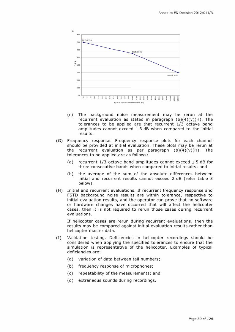
Annex to ED Decision 2012/011/R
Page 80 of 128
Fi
30 dB @ 16 kHz
55 dB @ 1 kHz
70 dB @ 50 Hz
0.0
10.0
20.0
30.0
40.0
50.0
60.0
70.0
80.0
50
63
80
100
125
160
200
250
315
400
500
630
800
1000
1250
1600
2000
2500
3150
4000
5000
6300
8000
100
00
125
00
160
00
Figure 3. 1/3 Octave Band Frequency (Hz)
dBSP
L
(c) The background noise measurement may be rerun at the recurrent evaluation as stated in paragraph (b)(4)(v)(H). The tolerances to be applied are that recurrent 1/3 octave band amplitudes cannot exceed 3 dB when compared to the initial results.
(G) Frequency response. Frequency response plots for each channel should be provided at initial evaluation. These plots may be rerun at the recurrent evaluation as per paragraph (b)(4)(v)(H). The tolerances to be applied are as follows:
(a) recurrent 1/3 octave band amplitudes cannot exceed 5 dB for three consecutive bands when compared to initial results; and
(b) the average of the sum of the absolute differences between initial and recurrent results cannot exceed 2 dB (refer table 3 below).
(H) Initial and recurrent evaluations. If recurrent frequency response and FSTD background noise results are within tolerance, respective to initial evaluation results, and the operator can prove that no software or hardware changes have occurred that will affect the helicopter cases, then it is not required to rerun those cases during recurrent evaluations.
If helicopter cases are rerun during recurrent evaluations, then the results may be compared against initial evaluation results rather than helicopter master data.
(I) Validation testing. Deficiencies in helicopter recordings should be considered when applying the specified tolerances to ensure that the simulation is representative of the helicopter. Examples of typical deficiencies are:
(a) variation of data between tail numbers;
(b) frequency response of microphones;
(c) repeatability of the measurements; and
(d) extraneous sounds during recordings.
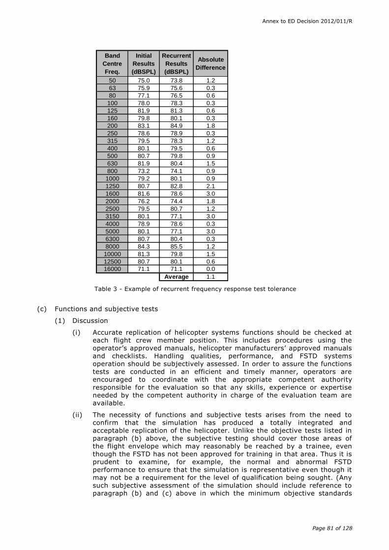
Annex to ED Decision 2012/011/R
Page 81 of 128
Band
Centre
Freq.
Initial
Results
(dBSPL)
Recurrent
Results
(dBSPL)
Absolute
Difference
50 75.0 73.8 1.2
63 75.9 75.6 0.3
80 77.1 76.5 0.6
100 78.0 78.3 0.3
125 81.9 81.3 0.6
160 79.8 80.1 0.3
200 83.1 84.9 1.8
250 78.6 78.9 0.3
315 79.5 78.3 1.2
400 80.1 79.5 0.6
500 80.7 79.8 0.9
630 81.9 80.4 1.5
800 73.2 74.1 0.9
1000 79.2 80.1 0.9
1250 80.7 82.8 2.1
1600 81.6 78.6 3.0
2000 76.2 74.4 1.8
2500 79.5 80.7 1.2
3150 80.1 77.1 3.0
4000 78.9 78.6 0.3
5000 80.1 77.1 3.0
6300 80.7 80.4 0.3
8000 84.3 85.5 1.2
10000 81.3 79.8 1.5
12500 80.7 80.1 0.6
16000 71.1 71.1 0.0
Average 1.1
Table 3 - Example of recurrent frequency response test tolerance
(c) Functions and subjective tests
(1) Discussion
(i) Accurate replication of helicopter systems functions should be checked at each flight crew member position. This includes procedures using the operator’s approved manuals, helicopter manufacturers’ approved manuals and checklists. Handling qualities, performance, and FSTD systems operation should be subjectively assessed. In order to assure the functions tests are conducted in an efficient and timely manner, operators are encouraged to coordinate with the appropriate competent authority responsible for the evaluation so that any skills, experience or expertise needed by the competent authority in charge of the evaluation team are available.
(ii) The necessity of functions and subjective tests arises from the need to confirm that the simulation has produced a totally integrated and acceptable replication of the helicopter. Unlike the objective tests listed in paragraph (b) above, the subjective testing should cover those areas of the flight envelope which may reasonably be reached by a trainee, even though the FSTD has not been approved for training in that area. Thus it is prudent to examine, for example, the normal and abnormal FSTD performance to ensure that the simulation is representative even though it may not be a requirement for the level of qualification being sought. (Any such subjective assessment of the simulation should include reference to paragraph (b) and (c) above in which the minimum objective standards

Annex to ED Decision 2012/011/R
Page 82 of 128
acceptable for that qualification level are defined. In this way it is possible to determine whether simulation is an absolute requirement or just one where an approximation, if provided, has to be checked to confirm that it does not contribute to negative training.)
(iii) At the request of the competent authority, the FSTD may be assessed for a special aspect of an operator’s training programme during the functions and subjective portion of an evaluation. Such an assessment may include a portion of a line oriented flight training (LOFT) scenario or special emphasis items in the operator’s training programme. Unless directly related to a requirement for the current qualification level, the results of such an evaluation would not affect the FSTD’s current status.
(iv) Functions tests should be run in a logical flight sequence at the same time as performance and handling assessments. This also permits real time FSTD running for two to three hours, without repositioning or flight or position freeze, thereby permitting proof of reliability.
(2) Test requirements
(i) The ground and flight tests and other checks required for qualification are listed in the table of functions and subjective tests. The table includes manoeuvres and procedures to assure that the FSTD functions and performs appropriately for use in pilot training, testing and checking in the manoeuvres and procedures normally required of a training, testing and checking programme.
(ii) Manoeuvres and procedures are included to address some features of advanced technology helicopters and innovative training programmes.
(iii) All systems functions should be assessed for normal and, where appropriate, alternate operations. Normal, abnormal, and emergency procedures associated with a flight phase should be assessed during the evaluation of manoeuvres or events within that flight phase. Systems are listed separately under ‘any flight phase’ to assure appropriate attention to systems checks.
(iv) When evaluating functions and subjective tests, the fidelity of simulation required for the highest level of qualification should be very close to the helicopter. However, for the lower levels of qualification the degree of fidelity may be reduced in accordance with the criteria contained in paragraph (b) above.
(v) Evaluation of the lower orders of FSTDs should be tailored only to the systems and flight conditions which have been simulated. Similarly, many tests should be applicable for automatic flight. Where automatic flight is not possible and pilot manual handling is required, the FSTD should be at least controllable to permit the conduct of the flight.
(vi) Any additional capability provided in excess of the minimum required standards for a particular qualification level should be assessed to ensure the absence of any negative impact on the intended training and testing manoeuvres.
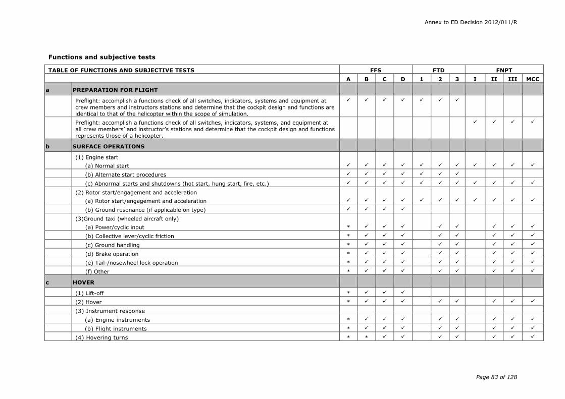
Annex to ED Decision 2012/011/R
Page 83 of 128
Functions and subjective tests
TABLE OF FUNCTIONS AND SUBJECTIVE TESTS FFS FTD FNPT
A B C D 1 2 3 I II III MCC
a PREPARATION FOR FLIGHT
Preflight: accomplish a functions check of all switches, indicators, systems and equipment at crew members and instructors stations and determine that the cockpit design and functions are identical to that of the helicopter within the scope of simulation.
Preflight: accomplish a functions check of all switches, indicators, systems, and equipment at all crew members’ and instructor’s stations and determine that the cockpit design and functions represents those of a helicopter.
b SURFACE OPERATIONS
(1) Engine start
(a) Normal start
(b) Alternate start procedures
(c) Abnormal starts and shutdowns (hot start, hung start, fire, etc.)
(2) Rotor start/engagement and acceleration
(a) Rotor start/engagement and acceleration
(b) Ground resonance (if applicable on type)
(3)Ground taxi (wheeled aircraft only)
(a) Power/cyclic input
*
(b) Collective lever/cyclic friction *
(c) Ground handling *
(d) Brake operation *
(e) Tail-/nosewheel lock operation *
(f) Other *
c HOVER
(1) Lift-off *
(2) Hover *
(3) Instrument response
(a) Engine instruments *
(b) Flight instruments *
(4) Hovering turns * *
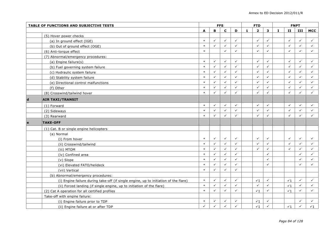
Annex to ED Decision 2012/011/R
Page 84 of 128
TABLE OF FUNCTIONS AND SUBJECTIVE TESTS FFS FTD FNPT
A B C D 1 2 3 I II III MCC
(5) Hover power checks
(a) In ground effect (IGE) *
(b) Out of ground effect (OGE) *
(6) Anti-torque effect *
(7) Abnormal/emergency procedures:
(a) Engine failure(s) *
(b) Fuel governing system failure *
(c) Hydraulic system failure *
(d) Stability system failure *
(e) Directional control malfunctions *
(f) Other *
(8) Crosswind/tailwind hover *
d AIR TAXI/TRANSIT
(1) Forward *
(2) Sideways *
(3) Rearward *
e TAKE-OFF
(1) Cat. B or single engine helicopters
(a) Normal
(i) From hover
*
(ii) Crosswind/tailwind *
(iii) MTOM *
(iv) Confined area *
(v) Slope *
(vi) Elevated FATO/helideck *
(vii) Vertical *
(b) Abnormal/emergency procedures:
(i) Engine failure during take-off (if single engine, up to initiation of the flare) * 1 1
(ii) Forced landing (if single engine, up to initiation of the flare) * 1
(2) Cat A operation for all certified profiles * 1 1
Take-off with engine failure:
(i) Engine failure prior to TDP * 1
(ii) Engine failure at or after TDP 1 1 1
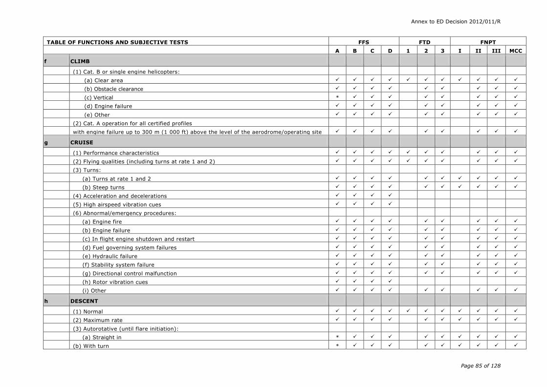
Annex to ED Decision 2012/011/R
Page 85 of 128
TABLE OF FUNCTIONS AND SUBJECTIVE TESTS FFS FTD FNPT
A B C D 1 2 3 I II III MCC
f CLIMB
(1) Cat. B or single engine helicopters:
(a) Clear area
(b) Obstacle clearance
(c) Vertical *
(d) Engine failure
(e) Other
(2) Cat. A operation for all certified profiles
with engine failure up to 300 m (1 000 ft) above the level of the aerodrome/operating site
g CRUISE
(1) Performance characteristics
(2) Flying qualities (including turns at rate 1 and 2)
(3) Turns:
(a) Turns at rate 1 and 2
(b) Steep turns
(4) Acceleration and decelerations
(5) High airspeed vibration cues
(6) Abnormal/emergency procedures:
(a) Engine fire
(b) Engine failure
(c) In flight engine shutdown and restart
(d) Fuel governing system failures
(e) Hydraulic failure
(f) Stability system failure
(g) Directional control malfunction
(h) Rotor vibration cues
(i) Other
h DESCENT
(1) Normal
(2) Maximum rate
(3) Autorotative (until flare initiation):
(a) Straight in *
(b) With turn *

Annex to ED Decision 2012/011/R
Page 86 of 128
TABLE OF FUNCTIONS AND SUBJECTIVE TESTS FFS FTD FNPT
A B C D 1 2 3 I II III MCC
i VISUAL APPROACHES
(1) Cat. B or single engine helicopters:
(a) Approach
(i) Normal
(ii) Steep
(iii) Shallow
(iv) Vertical
(b) Abnormal and emergency procedures:
(i) One engine inoperative
(ii) Fuel governing failure
(iii) Hydraulics failure
(iv) Stability system failure
(v) Directional control failure
(vi) Autorotation
(vii) Other
(c) Balked landing:
(i) All engines operating
(ii) One or more engines inoperative
(2) Cat. A operation for all certified profiles:
(a) from 300 m (1 000 ft) above the level of the aerodrome/operating site to or after LDP
j INSTRUMENT APPROACHES
Only those instrument approach tests relevant to the simulated helicopter type or system(s) and MCC training should be selected from the following list.
(1) Non-precision:
(a) All engines operating
(b) One or more engines inoperative
(c) Approach procedures:
(i) NDB
(ii) VOR/DME, RNAV
(iii) ARA (Airborne radar approach)
(iv) GPS
(v) Other
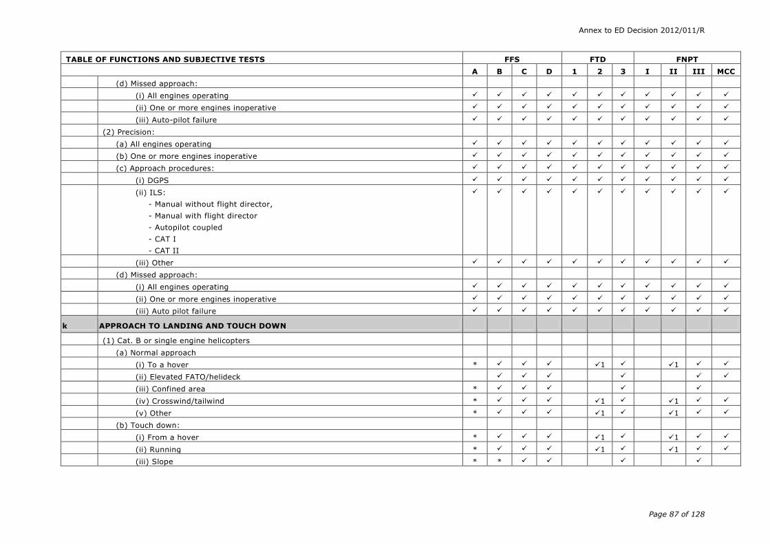
Annex to ED Decision 2012/011/R
Page 87 of 128
TABLE OF FUNCTIONS AND SUBJECTIVE TESTS FFS FTD FNPT
A B C D 1 2 3 I II III MCC
(d) Missed approach:
(i) All engines operating
(ii) One or more engines inoperative
(iii) Auto-pilot failure
(2) Precision:
(a) All engines operating
(b) One or more engines inoperative
(c) Approach procedures:
(i) DGPS
(ii) ILS:
- Manual without flight director,
- Manual with flight director
- Autopilot coupled
- CAT I
- CAT II
(iii) Other
(d) Missed approach:
(i) All engines operating
(ii) One or more engines inoperative
(iii) Auto pilot failure
k APPROACH TO LANDING AND TOUCH DOWN
(1) Cat. B or single engine helicopters
(a) Normal approach
(i) To a hover * 1 1
(ii) Elevated FATO/helideck
(iii) Confined area *
(iv) Crosswind/tailwind * 1 1
(v) Other * 1 1
(b) Touch down:
(i) From a hover * 1 1
(ii) Running * 1 1
(iii) Slope * *
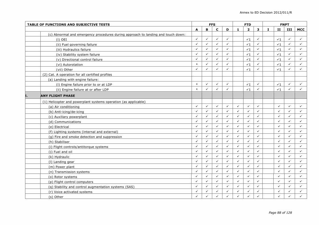
Annex to ED Decision 2012/011/R
Page 88 of 128
TABLE OF FUNCTIONS AND SUBJECTIVE TESTS FFS FTD FNPT
A B C D 1 2 3 I II III MCC
(c) Abnormal and emergency procedures during approach to landing and touch down:
(i) OEI 1 1
(ii) Fuel governing failure 1 1
(iii) Hydraulics failure 1 1
(iv) Stability system failure 1 1
(v) Directional control failure 1 1
(vi) Autorotation * 1 1
(vii) Other 1 1
(2) Cat. A operation for all certified profiles
(a) Landing with engine failure:
(i) Engine failure prior to or at LDP * 1 1
(ii) Engine failure at or after LDP * 1 1
l. ANY FLIGHT PHASE
(1) Helicopter and powerplant systems operation (as applicable)
(a) Air conditioning
(b) Anti-icing/de-icing
(c) Auxiliary powerplant
(d) Communications
(e) Electrical
(f) Lighting systems (internal and external)
(g) Fire and smoke detection and suppression
(h) Stabiliser
(i) Flight controls/antitorque systems
(j) Fuel and oil
(k) Hydraulic
(l) Landing gear
(m) Power plant
(n) Transmission systems
(o) Rotor systems
(p) Flight control computers
(q) Stability and control augmentation systems (SAS)
(r) Voice activated systems
(s) Other

Annex to ED Decision 2012/011/R
Page 89 of 128
TABLE OF FUNCTIONS AND SUBJECTIVE TESTS FFS FTD FNPT
A B C D 1 2 3 I II III MCC
(2) Flight management and guidance systems (as applicable)
(a) Airborne radar
(b) Automatic landing aids
(c) Autopilot
(d) Collision avoidance systems (GPWS, ACAS,.)
(e) Flight data displays
(f) Flight management computers
(g) Head-up displays
(h) Navigation system
(i) NVG
(j) Other
(3) Airborne procedures
(a) Quickstop * *
(b) Holding pattern
(c) Hazard avoidance (GPWS, TCAS, Weather radar). As applicable, except for weather radar required for MCC training in FNPT.
* *
(d) Retreating blade stall recovery (as applicable) *
(e) Rotor mast bumping (as applicable)
(f) Vortex ring *
m ENGINE SHUTDOWN AND PARKING
(1) Engine and systems operation
(2) Parking brake operation
(3) Rotor brake operation
(4) Abnormal and emergency procedures
(5) Other
n MOTION EFFECTS
(1) Runway rumble, oleo deflections, effects of ground speed and uneven surface characteristics
*
(2) Buffet due to translational lift *
(3) Buffet during extension and retraction of landing gear *
(4) Buffet due to high speed and retreating blade stall *
(5) Buffet due to vortex ring *
(6) Representative cues resulting from touch down *
(7) Rotor(s) vibrations (motion cues)
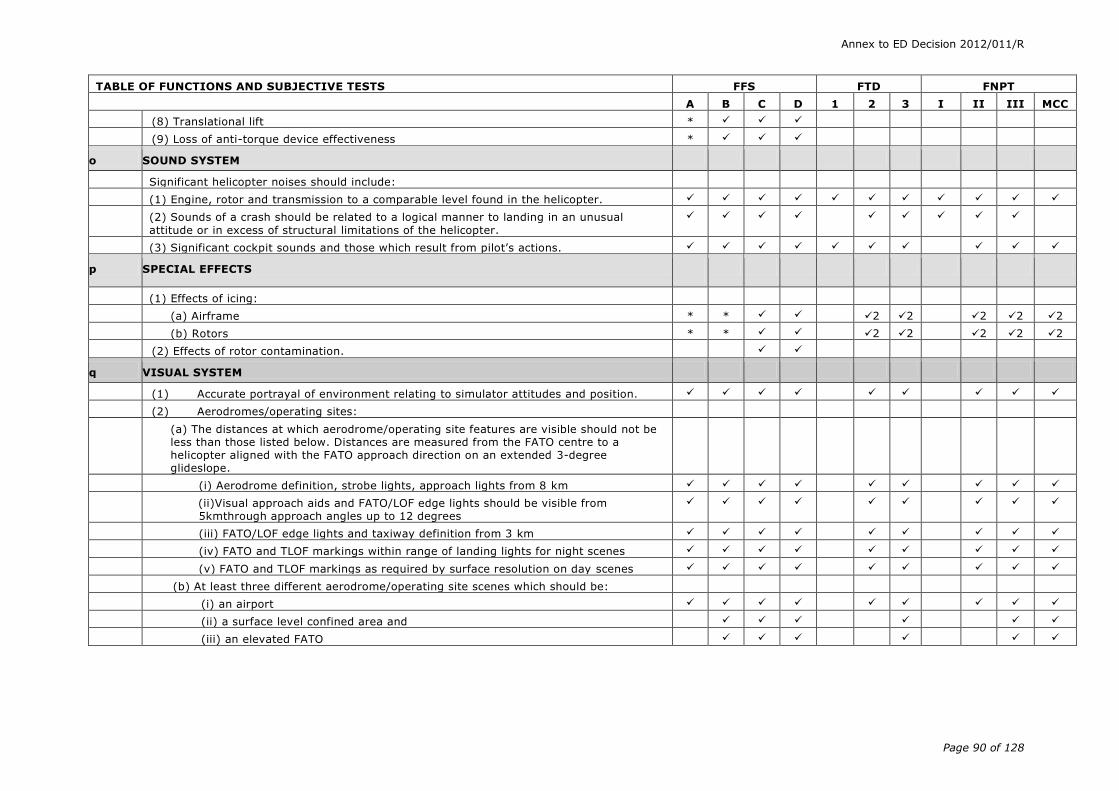
Annex to ED Decision 2012/011/R
Page 90 of 128
TABLE OF FUNCTIONS AND SUBJECTIVE TESTS FFS FTD FNPT
A B C D 1 2 3 I II III MCC
(8) Translational lift *
(9) Loss of anti-torque device effectiveness *
o SOUND SYSTEM
Significant helicopter noises should include:
(1) Engine, rotor and transmission to a comparable level found in the helicopter.
(2) Sounds of a crash should be related to a logical manner to landing in an unusual
attitude or in excess of structural limitations of the helicopter.
(3) Significant cockpit sounds and those which result from pilot’s actions.
p SPECIAL EFFECTS
(1) Effects of icing:
(a) Airframe * * 2 2 2 2 2
(b) Rotors * * 2 2 2 2 2
(2) Effects of rotor contamination.
q VISUAL SYSTEM
(1) Accurate portrayal of environment relating to simulator attitudes and position.
(2) Aerodromes/operating sites:
(a) The distances at which aerodrome/operating site features are visible should not be less than those listed below. Distances are measured from the FATO centre to a helicopter aligned with the FATO approach direction on an extended 3-degree glideslope.
(i) Aerodrome definition, strobe lights, approach lights from 8 km
(ii)Visual approach aids and FATO/LOF edge lights should be visible from 5kmthrough approach angles up to 12 degrees
(iii) FATO/LOF edge lights and taxiway definition from 3 km
(iv) FATO and TLOF markings within range of landing lights for night scenes
(v) FATO and TLOF markings as required by surface resolution on day scenes
(b) At least three different aerodrome/operating site scenes which should be:
(i) an airport
(ii) a surface level confined area and
(iii) an elevated FATO

Annex to ED Decision 2012/011/R
Page 91 of 128
TABLE OF FUNCTIONS AND SUBJECTIVE TESTS FFS FTD FNPT
A B C D 1 2 3 I II III MCC
(c) Representative aerodrome/operating site scene content including the following:
(i) Surfaces and markings on runways, operating sites, taxiways and ramps
(ii) Lighting for the FATO/TLOF, visual approach aids and approach lighting of appropriate colours
(iii) Aerodrome/operating site perimeter and taxiway lighting
(iv) Ramps and terminal buildings and vertical objects which correspond to the operational requirements of an operator’s LOFT scenario.
(v) The directionality of strobe lights, approach lights, runway edge lights, visual landing aids, runway centre line lights, threshold lights, and touch down zone lights on the runway of intended landing should be realistically replicated
(3) Representative visual effect of helicopter external lighting in reduced visibility, such as reflected glare, to include landing lights, strobes, and beacons
(4) Instructor controls of the following:
(a) Cloud base/cloud tops;
(b) Visibility in kilometres or nautical miles and RVR in meters or feet;
(c) Aerodrome/operating site selection;
(d) Aerodrome/operating site lighting;
(e) Ground and flight traffic.
(5) Visual system compatibility with aerodynamic programming
(6) Visual cues to assess sink rate displacements, rates and height AGL during landings (e.g. runways/operating sites, taxiways, ramps and terrain features).
*
(7) Visual scene capability:
(a) Twilight and night
(b) Twilight, night and day
(8) General terrain characteristics
Below 5 000 ft present realistic visual scene permitting navigation by sole reference to visual landmarks. Terrain contouring should be suitably represented.
*

Annex to ED Decision 2012/011/R
Page 92 of 128
TABLE OF FUNCTIONS AND SUBJECTIVE TESTS FFS FTD FNPT
A B C D 1 2 3 I II III MCC
(9) At and below 610 m (2 000 ft) height above the aerodrome/operating site and within a radius of 16 km (9 NM) from the aerodrome/operating site, weather representations, including the following:
(a) Variable cloud density
(b) Partial obscuration of ground scenes; the effect of a scattered to broken cloud deck
(c) Visual cues of speed through clouds
(d) Gradual break out
(e) Visibility and RVR measured in terms of distance
(f) Patchy fog
(g) The effect of fog on aerodrome/operating site lighting.
(10) A capability to present ground and air hazards such as another aircraft crossing the active runway and converging airborne traffic
(11) Operational visual scenes which provide a cue rich environment sufficient for precise low airspeed and low altitude manoeuvring and landing.
(12) Operational visual scenes which portray representative physical relationships known to cause landing illusions such as short runways, landing approaches over water, uphill, downhill and sloping landing areas, rising terrain on the approach path, and unique topographic features.
Note - illusions may be demonstrated at a generic aerodrome or specific aerodrome/ operating site.
(13) Special weather representations of light, medium, heavy precipitation and lighting
near a thunderstorm on take-off, approach and landing at and below an altitude of 610 m (2 000 ft) above the aerodrome/operating site surface and within a radius of 16 km (9 NM) from the aerodrome/operating site.
(14) Wet and snow-covered landing areas including runway/operating site lighting reflections for wet, partially obscured lights for snow or suitable alternative effects.
(15) The effects of swell and wind on a 3-dimensional ocean model should be simulated.
(16) The effects of own helicopter downwash upon various surfaces such as snow, sand, dirt and grass should be simulated including associated effects of reduced visibility.
(17) Realistic colour and directionality of aerodrome/operating site lighting.
(18) The visual scene should correlate with integrated helicopter systems, where fitted (e.g. terrain, traffic and weather avoidance systems and head-up guidance system (HUGS)) (For FTD and FNPT may be restricted to specific geographical areas.) Weather radar presentations in helicopters where radar information is presented on the pilot’s navigation instruments. Radar returns should correlate to the visual scene.
(19) Dynamic visual representation of rotor tip path plane including effects of rotor start up and shut down as well as orientation of the rotor disc due to pilot control input.

Annex to ED Decision 2012/011/R
Page 93 of 128
TABLE OF FUNCTIONS AND SUBJECTIVE TESTS FFS FTD FNPT
A B C D 1 2 3 I II III MCC
(20) To support LOFT, the visual system should provide smooth transition to new operational scenes without flight through clouds.
(21) The visual system should provide appropriate height and 3-D object collision detection feedback to support training.
(22) Scene quality
(a) surfaces and textural cues should be free from distracting quantisation (aliasing)
(b) the system lightpoints should be free from distracting jitter, smearing or streaking
(c) system capable of six discrete light step controls (0-5)
Notes
General: Motion and buffet cues should only be applicable to FSTD equipped with an appropriate motion system
(1) Limited to clear area profiles
(2) Limited to performance
* Check for the absence of negative effect

Annex to ED Decision 2012/011/R
Page 94 of 128
Appendix 1 to AMC1 FSTD(H).300 Validation test tolerances
(a) Background
(1) The tolerances listed in AMC1 FSTD(H).300 are designed to be a measure of quality of match using flight test data as a reference.
(2) There are many reasons, however, why a particular test may not fully comply with the prescribed tolerances:
(i) flight test is subject to many sources of potential error, e.g. instrumentation errors and atmospheric disturbance during data collection;
(ii) data that exhibit rapid variation or noise may also be difficult to match; or
(iii) engineering simulator data and other calculated data may exhibit errors due to a variety of potential differences discussed below.
(3) When applying tolerances to any test, good engineering judgement should be applied. Where a test clearly falls outside the prescribed tolerance(s) for no apparent reasons, then it should be judged to have failed.
(4) The use of non-flight test data as reference data was in the past quite small, and thus these tolerances were used for all tests. The inclusion of this type of data as a validation source has rapidly expanded, and will probably continue to expand.
(5) When engineering simulator data are used, the basis for their use is that the reference data are produced using the same simulation models as used in the equivalent flight training FSTD; i.e., the two sets of results should be ‘essentially’ similar. The use of flight test based tolerances may undermine the basis for using engineering simulator data, because an essential match is needed to demonstrate proper implementation of the data package.
(6) There are, of course, reasons why the results from the two sources can be expected to differ:
(i) hardware (avionics units and flight controls);
(ii) iteration rates;
(iii) execution order;
(iv) integration methods;
(v) processor architecture;
(vi) digital drift:
(A) interpolation methods;
(B) data handling differences; or
(C) auto-test trim tolerances, etc.
(7) Any differences should, however, be small and the reasons for any differences, other than those listed above, should be clearly explained.
(8) Historically, engineering simulation data were used only to demonstrate compliance with certain extra modelling features:
(i) flight test data could not reasonably be made available;
(ii) data from engineering simulations made up only a small portion of the overall validation data set; or
(iii) key areas were validated against flight test data.

Annex to ED Decision 2012/011/R
Page 95 of 128
(9) The current rapid increase in the use and projected use of engineering simulation data is an important issue because:
(i) flight test data are often not available due to sound technical reasons;
(ii) alternative technical solutions are being advanced; and
(iii) cost is an ever-present issue.
(10) Guidelines are therefore needed for the application of tolerances to engineering-simulator-generated validation data.
(b) Non-flight test tolerances
(1) Where engineering simulator data or other non-flight test data are used as an allowable form of reference validation data for the objective tests listed in the table of validation tests, the match obtained between the reference data and the FSTD results should be very close. It is not possible to define a precise set of tolerances as the reasons for other than an exact match will vary depending upon a number of factors discussed in paragraph (a) of this Appendix.
(2) As guidance, unless a rationale justifies a significant variation between the reference data and the FSTD results, 20% of the corresponding ‘flight test’ tolerances would be appropriate.
(3) For this guideline (20% of flight test tolerances) to be applicable, the data provider should supply a well-documented mathematical model and testing procedure that enables an exact replication of their engineering simulation results.

Annex to ED Decision 2012/011/R
Page 96 of 128
Appendix 2 to AMC1 FSTD(H).300 Validation data roadmap
(a) General
(1) Helicopter manufacturers or other sources of data should supply a validation data roadmap (VDR) document as part of the data package. A VDR document contains guidance material from the helicopter validation data supplier recommending the best possible sources of data to be used as validation data in the QTG. A VDR is of special value in the cases of requests for ‘interim’ qualification, and for qualification of alternate engine or avionics fits. A VDR should be submitted to the competent authority as early as possible in the planning stages for any FSTD planned for qualification to the standards contained herein. The respective Member State’s civil aviation authority is the final authority to approve the data to be used as validation material for the QTG.
(2) The validation data roadmap should clearly identify (in matrix format) sources of data for all required tests. It should also provide guidance regarding the validity of these data for a specific engine type and thrust rating configuration and the revision levels of all avionics affecting helicopter handling qualities and performance. The document should include rationale or explanation in cases where data or parameters are missing, engineering simulation data are to be used, flight test methods require explanation, etc., together with a brief narrative describing the cause/effect of any deviation from data requirements. Additionally, the document should make reference to other appropriate sources of validation data (e.g., sound and vibration data documents).
(3) Table 1, below, depicts a generic roadmap matrix identifying sources of validation data for an abbreviated list of tests. A complete matrix should address all test conditions.
(4) Additionally, two examples of ‘rationale pages’ are presented in Appendix F of IATA’s Flight Simulator Design & Performance Data Requirements. These illustrate the type of aircraft and avionics configuration information and descriptive engineering rationale used to describe data anomalies, provide alternative data, or provide an acceptable basis to the competent authority for obtaining deviations from QTG validation requirements.
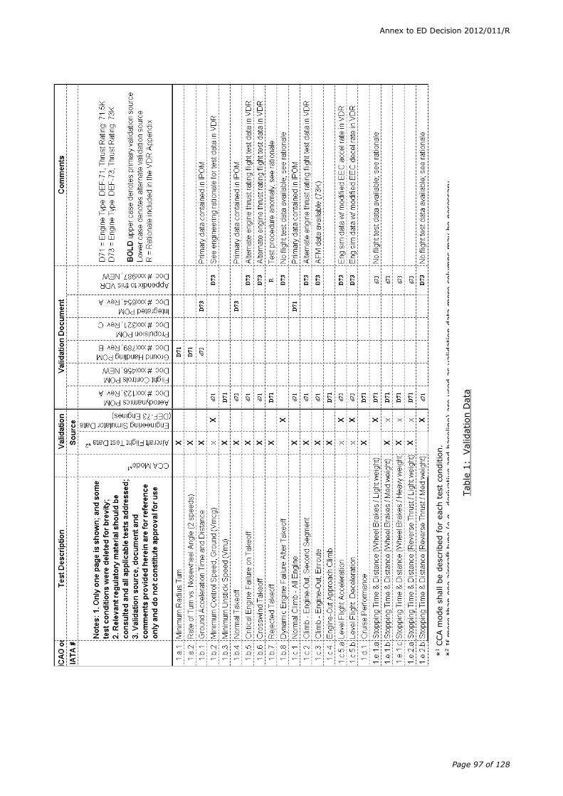
Annex to ED Decision 2012/011/R
Page 97 of 128
*1 C
CA m
ode s
hall b
e d
escribed for
each t
est
conditio
n.
*2 I
f m
ore
than o
ne a
ircra
ft t
ype (
e.g
., d
erivative a
nd b
aseline)
are
used a
s v
alidation d
ata
more
colu
mns m
ay b
e n
ecessary
.
Table
1:
Validation D
ata

Annex to ED Decision 2012/011/R
Page 98 of 128
Appendix 3 to AMC1 FSTD(H).300 Rotor aerodynamic modelling techniques
(a) Introduction
Several modelling choices are available to simulate rotor blade aerodynamics. These include rotor disks, rotor maps, and blade element rotor models. Cost, simulation fidelity, and training requirements are three factors that may determine the appropriate model to use.
(b) Disk models
(1) Rotor disk models typically approximate blade flapping by the first few terms of a Fourier series. The lift curve is assumed to be a linear function of angle of attack and inflow is usually assumed to be uniform over the entire disk. With these assumptions the forces and moments produced by the blades over the course of one complete revolution can be written analytically. Blade azimuthal position can then be ignored by the rest of the helicopter aerodynamic model, which sees normalised forces as generated by a thrust producing disk. Disk models are usually easy to implement and tune, and require minimal computer resources to run. Disk models are best at matching static performance characteristics, and weakest in matching dynamic handling qualities and flight at extremes of the flight envelope where some of the underlying assumptions cease to be true. The risk is that these models may require an unmanageable accumulation of add-ons to simulate all the helicopter effects that do not flow naturally out of the model such as blade stall, dynamic stall, reverse flow, and cross coupling effects. For certain helicopter types, and for many tail rotors, some of these effects will be negligible or occur outside of the civil flight envelope and thus not impact the training requirements of the FSTD. Adding the effects of sharp wind gradients over the rotor disk, which may occur in confined areas or in pinnacle training, is problematic, as the formulation assumes constant wind speed over the disk.
Figure 1
(c) Rotor map models
(1) Rotor map models, or coefficient models, are also not computationally demanding. With this method a database of coefficients or stability and control derivatives is used to compute aircraft forces and moments. The simulation should interpolate its performance from the nearest points in the database. This database can be generated from flight test data analysis or from an off-line blade element model. Steady state performance can in theory be easily tuned by simply adjusting data points in the database. However, if the database is generated from an off-line model blade element model then considerable effort could be spent tuning the off-line model that is one step removed from the

Annex to ED Decision 2012/011/R
Page 99 of 128
simulation. The net result is a saving in real time execution, but development costs may be as high as a full blade element model. The blade element model that generates the database, since it runs off-line, is not limited by real time constraints and thus can be considerably more complex than real time blade element models.
FSTD fidelity may be limited by the overall size and coarseness of the database. Not every flight possibility should be covered by the database and separate databases may need to be generated to simulate failure modes. As with the rotor disk model the incorporation of known air flows into the simulation at the blade elements is problematic and could effect for example, the realism of simulated turbulence, and the effectiveness of confined area landing training where the winds have large gradients such that they will not be constant over the entire rotor disk.
Figure 2
(d) Blade element rotor models
(1) A blade element rotor model has at its core a division of the blade into discrete segments. Rotor speed and radial station as well as local winds at each segment are used to compute local angle of attack, sideslip and Mach number. Using the airfoil characteristics of airfoil at the blade segment aerodynamic forces are computed. Once all the forces and moments for all segments have been computed the equations of motion of each blade are solved. Real time constraints may limit the number of segments, and the degrees of freedom/flexibility of the blades and the complexity of the inflow model. A real time blade element model and its associated inflow model are significantly more complex than a rotor disk, but offer a more rigorous simulation of a helicopter rotor blade dynamics. Blade motions even at very low rotor speeds are computed in the same manner, thus offering fidelity simulation of helicopter operations from rotor stopped, through start-up, to the full flight envelope including malfunctions and the effects of sharp wind gradients across the blade elements that occur in confined areas or in pinnacle training. The model can be used to provide helicopter vibrations amplitudes and trends.
Figure 3
(e) Conclusions
(1) The modelling choice alone cannot ensure fidelity. The best guarantor of accurate simulation training remains validation with flight test data. A blade element rotor

Annex to ED Decision 2012/011/R
Page 100 of 128
model reduces risk to simulation training by giving a more comprehensive rotor simulation, but comes at a price of increased complexity and computer resource requirements. This may be warranted where the training objectives of the simulation require a very high level of fidelity.

Annex to ED Decision 2012/011/R
Page 101 of 128
Appendix 4 to AMC1 FSTD(H).300 Vibration platforms for helicopter FSTDs
(a) The role of vibrations in pilot cueing
(1) Motion feedback in rotary wing aircraft has a wide bandwidth of frequencies and amplitudes consisting of cues ranging from large sustained accelerations up to high frequency vibrations generated by the rotor harmonics. Vibrations on helicopters, in addition to creating a harsh operating environment, provide pilots with rotor dynamic feedback critical to his/her ability to control the aircraft. Normal and abnormal flying conditions are therefore sensed by the pilots through the vibration levels/amplitudes and are integral to helicopter flying. Rotor malfunctions/conditions such as icing or damage are rapidly identified subjectively by sensing the increased vibration levels and change in characteristics.
(2) The FSTD training environment should subject the pilot to high fidelity and realistic levels of vibration in order to enhance the transfer of training. Vibrations, when accurately simulated and harmonised with visual and sound system cues, ensure that the pilot develops proper control strategies while experiencing representative workloads.
(3) Three characteristics of the vibrations must be accurately reproduced to create an authentic flying environment and stimulate pilots with representative aircraft vibrations: the trends, the axes and the levels of vibrations. For example, the vibration trends will inform the pilot that the helicopter has entered a transition stage between hover and low speed level flight. Helicopter vibrations are multidimensional, that is, they are perceived as occurring in more than one degree of freedom at a time. Simulating combinations of X, Y and Z vibrations has demonstrated to be significant for pilot training. Accurate reproduction of vibration levels provides subjective information on the stresses that certain manoeuvres exert on the helicopter.
(b) Limitations of using a 6-degree-of-freedom motion system to reproduce vibrations
(1) The simulation of vibration cues for rotary wing aircraft as produced by a conventional six-degree-of-freedom (6-DOF) motion system is limited. While most motion systems are capable of reproducing vibrations, the dynamic range of helicopter vibration amplitudes and frequencies (3 Hz - 50 Hz typically) exceed the limited bandwidth capability of synergistic motion systems (typically 0 Hz - 10 Hz in the vertical axis and lower in the longitudinal and lateral axes).
(2) Moreover, the application of representative vibrations to the entire simulator structure may adversely impact the life span of some simulator components such as the visual system.
(c) Advantages of a dedicated 3-degree-of-freedom vibration platform
(1) To augment the performance of a 6-DOF motion system and achieve accurate reproduction of vibrations while minimizing stresses on the simulator structure, it is proposed that the motion cueing frequency bandwidth be separated in two. Dedicated cueing devices would then be assigned to reproduce each specific frequency range. The lower frequency range is used to drive the motion system and the higher frequency range, with the majority of the vibration information, is used to drive the vibration platform.
(2) Two solutions may be used for simulating the vibrations:
(i) A vibration platform consisting of a 3-DOF system tailored for vibrations and installed under the cockpit as illustrated in figure 1. This system combines high bandwidth, independent driving axes (to avoid crosstalk) and high stiffness.

Annex to ED Decision 2012/011/R
Page 102 of 128
(ii) A vibration platform consisting of a 3-DOF system to make the seats, the controls and the main instrument board vibrate independently from the cockpit. This solution decreases the moving mass relatively to the payload and therefore minimises the risk of resonance.
Figure 1: An Example of a 3-degree-of-freedom cockpit vibration system
VIBRATINGCOCKPIT
Annex to ED Decision 2012/011/R
Page 103 of 128
Appendix 5 to AMC1 FSTD(H).300 Transport delay testing method
(a) General
(1) The purpose of this Appendix is to demonstrate how to determine the introduced
transport delay through the FSTD system such that it does not exceed a specific
time delay. That is, measure the transport delay from control inputs through the
interface, through each of the host computer modules and back through the
interface to motion, flight instrument and visual systems, and show that it is no
more than the tolerances required in the validation test tables.
(2) Four specific examples of transport delay are described as follows:
(i) simulation of classic non-computer controlled aircraft;
(ii) simulation of computer controlled aircraft using real aircraft equipment;
(iii) simulation of computer controlled aircraft using software emulation of
aircraft equipment; and
(iv) simulation using software avionics or re-hosted instruments.
(3) Figure 1 illustrates the total transport delay for a non-computer-controlled
aircraft, or the classic transport delay test.
(4) Since there are no aircraft-induced delays for this case, the total transport delay
is equivalent to the introduced delay.
(5) Figure 2 illustrates the transport delay testing method employed on an FSTD that
uses the real aircraft controller system.
(6) To obtain the induced transport delay for the motion, instrument and visual
signal, the delay induced by the aircraft controller should be subtracted from the
total transport delay. This difference represents the introduced delay.
(7) Introduced transport delay is measured from the cockpit control input to the
reaction of the instruments, and motion and visual systems (See figure 1).
(8) Alternatively, the control input may be introduced after the aircraft controller
system and the introduced transport delay measured directly from the control
input to the reaction of the instruments, and FSTD motion and visual systems
(See figure 2).
(9) Figure 3 illustrates the transport delay testing method employed on an FSTD that
uses a software emulated aircraft controller system.
(10) By using the simulated aircraft controller system architecture for the pitch, roll
and yaw axes, it is not possible to measure simply the introduced transport
delay. Therefore, the signal should be measured directly from the pilot
controller. Since in the real aircraft the controller system has an inherent delay
as provided by the aircraft manufacturer, the FSTD manufacturer should
measure the total transport delay and subtract the inherent delay of the actual
aircraft components and ensure that the introduced delay does not exceed the
tolerances required in the validation test tables.
(11) Special measurements for instrument signals for FSTDs using a real aircraft
instrument display system, versus a simulated or re-hosted display. For the case
of the flight instrument systems, the total transport delay should be measured,
and the inherent delay of the actual aircraft components subtracted to ensure
that the introduced delay does not exceed the tolerances required in the
validation test tables.

Annex to ED Decision 2012/011/R
Page 104 of 128
(i) Figure 4A illustrates the transport delay procedure without the simulation
of aircraft displays. The introduced delay consists of the delay between the
control movement and the instrument change on the data bus.
(ii) Figure 4B illustrates the modified testing method required to correctly
measure introduced delay due to software avionics or re-hosted
instruments. The total simulated instrument transport delay is measured
and the aircraft delay should be subtracted from this total. This difference
represents the introduced delay and should not exceed the tolerances
required in the validation test tables. The inherent delay of the aircraft
between the data bus and the displays is indicated as XX ms (see figure
4A). The display manufacturer should provide this delay time.
(12) Recorded signals. The signals recorded to conduct the transport delay
calculations should be explained on a schematic block diagram. The FSTD
manufacturer should also provide an explanation of why each signal was selected
and how they relate to the above descriptions.
(13) Interpretation of results. It is normal that FSTD results vary over time from test
to test. This can easily be explained by a simple factor called ‘sampling
uncertainty’. All FSTDs run at a specific rate where all modules are executed
sequentially in the host computer. The flight controls input can occur at any time
in the iteration, but these data should not be processed before the start of the
new iteration. For an FSTD running at 60 Hz a worst-case difference of 16.67 ms
can be expected. Moreover, in some conditions, the host FSTD and the visual
system do not run at the same iteration rate, therefore the output of the host
computer to the visual will not always be synchronised.
(14) The transport delay test should account for the worst-case mode of operation of
the visual system. The tolerance is as required in the validation test tables and
motion response should occur before the end of the first video scan containing
new information.
Figure 1: Transport delay for simulation of classic non-computer-controlled aircraft
Flight
controls
input
Simulator
flight control
interface
HOST
Ÿ Instruments
Ÿ Motion
Ÿ Visual
Ÿ Instruments
reaction
Ÿ Motion
reaction
Ÿ Visual
reaction
Simulator introduced transport delay
Total simulator transport delay

Annex to ED Decision 2012/011/R
Page 105 of 128
Figure 2: Transport delay for simulation of computer-controlled aircraft using real aircraft equipment
Figure 3: Transport delay for simulation of computer-controlled aircraft using software emulation of aircraft equipment
Figure 4A and 4B: Transport delay for simulation of aircraft using real or re-hosted instrument drivers
Flight
controls
input
Aircraft
controller
system
Simulator
flight
control
interface
Aircraft delay
HOST
Instruments
Motion
Visual
Ÿ Instruments
reaction
Ÿ Motion reaction
Ÿ Visual reaction
Simulator introduced delay
Total simulator transport delay
Flight
controls
input
Simulator
flight
control
interface
Simulated
aeroplane
controller
system
HOST
Ÿ Instruments
Ÿ Motion
Ÿ Visual
Ÿ Instruments
reaction
Ÿ Motion
reaction
Ÿ Visual
reaction
Total simulator transport delay
Total transport delay (including aircraft delays)
Aircraft hardware
Display unit
Software avionics
or
Re-hosted
instrument
Interface
Control,
Flight,
Instruments,
Software
Flight controls
signal
Host computer Flight control cabinet
B: FSTD using software avionics or re-hosted instruments
A: FSTD using real aircraft instruments
Flight control cabinet Host computer
Flight controls
signal
Control,
Flight,
Instruments,
Software Interface
Delay < req’d value
Data
bus
Aircraft hardware
Display unit
Aircraft delay = XX msec
EFIS symbol
generator

Annex to ED Decision 2012/011/R
Page 106 of 128
Appendix 6 to AMC1 FSTD(H).300 Recurrent evaluations - validation test data
presentation
(a) Background
(1) During the initial evaluation of an FSTD the MQTG is created. This is the master document, as amended, to which FSTD recurrent evaluation test results are compared.
(2) The currently accepted method of presenting recurrent evaluation test results is to provide FSTD results over-plotted with reference data. Test results are carefully reviewed to determine if the test is within the specified tolerances. This can be a time consuming process, particularly when reference data exhibits rapid variations or an apparent anomaly requiring engineering judgement in the application of the tolerances. In these cases the solution is to compare the results to the MQTG. If the recurrent results are the same as those in the MQTG, the test is accepted. Both the FSTD operator and the competent authority are looking for any change in the FSTD performance since initial qualification.
(b) Recurrent evaluation test results presentation
(1) To promote a more efficient recurrent evaluation, FSTD operators are encouraged to over-plot recurrent validation test results with MQTG FSTD results recorded during the initial evaluation and as amended. Any change in a validation test will be readily apparent. In addition to plotting recurrent validation test and MQTG results, operators may elect to plot reference data as well.
(2) For full flight simulators (FFSs) and flight training devices (FTDs: when tests are not based on CT&M) there are no suggested tolerances between the recurrent test results and the MQTG validation test results of the initial evaluation. Investigation of any discrepancy between the MQTG and recurrent FFS/FTD performance is left to the discretion of the FSTD operator and the competent authority. For devices where CT&M is used for the initial evaluation, the test results for the recurrent evaluation should be acceptable if they are within the tolerances to the MQTG test results as given in AMC1 FSTD(H).300 (b)(3).
(3) Differences between the two sets of results, other than minor variations attributable to repeatability issues (see Appendix 1 of this AMC) that cannot easily be explained, may require investigation.
(4) The FSTD should still retain the capability to over-plot both automatic and manual validation test results with reference data.
(5) For FNPT special consideration for recurrent qualification is provided in AMC5 FSTD (H).300 paragraph (e)(4).
Annex to ED Decision 2012/011/R
Page 107 of 128
Appendix 7 to AMC1 FSTD(H).300 Applicability of CS-FSTD amendments to FSTD
data packages for existing aircraft
Except where specifically indicated, otherwise within AMC1 FSTD(H).300 paragraph (b)(3), validation data for QTG objective tests are expected to be derived from helicopter flight testing.
Ideally, data packages for all new FSTD should fully comply with the current standards for qualifying FSTDs.
For types of helicopters first entering into service after the publication of a new amendment of CS-FSTD(H), the provision of acceptable data to support the FSTD qualification process is a matter of planning and regulatory agreement.
For helicopters certificated prior to the release of the current amendment of CS-FSTD(H), it may not always be possible to provide the required data for any new or revised objective test cases compared to the previous amendments. After certification, manufacturers do not normally keep flight test aircraft available with the required instrumentation to gather additional data. In the case of flight test data gathered by independent data providers, it is most unlikely that the test aircraft will still be available.
Notwithstanding the above discussion, except where other types of data are already acceptable (see, for example, AMC6 and AMC7 FSTD(H).300), the preferred source of validation data is flight test. It is expected that best endeavours will be made by data suppliers to provide the required flight test data. If any flight test data exist (flown during the certification or any other flight test campaigns) that addresses the requirement, these test data should be provided. If any possibility exists to do this flight test during the occasion of a new flight test campaign, this should be done and provided in the data package at the next issue. Where these flight test data are genuinely not available, alternative sources of data may be acceptable using the following hierarchy of preferences:
first: flight test at an alternate but near equivalent condition/configuration;
second: data from an audited engineering simulation as defined in AMC1 FSTD(H).200 paragraph (a)(1) from an acceptable source (for example meets the guidelines laid out in AMC6 FSTD(H).300 paragraph (b)), or as used for aircraft certification;
third: aircraft performance data as defined in AMC1 FSTD(H).200 paragraph (a)(1) or other approved published sources (e.g., Production flight test schedule) for the following tests:
(i) 1d hover performance (IGE, OGE); and
(ii) 1g climb performance (AEO, OEI);
fourth: where no other data is available then, in exceptional circumstances only, the following sources may be acceptable subject to a case-by-case review with the competent authorities concerned taking into consideration the level of qualification sought for the FSTD:
(i) unpublished but acceptable sources e.g., calculations, simulations, video or other simple means of flight test analysis or recording; or
(ii) footprint test data from the actual training FSTD requiring qualification validated by competent authority appointed pilot subjective assessment.
In certain cases, it may make good engineering sense to provide more than one test to support a particular objective test requirement.
For helicopters certified prior to the date of issue of an amendment, an operator may, after reasonable attempts have failed to obtain suitable flight test data, indicate in the MQTG where flight test data are unavailable or unsuitable for a specific test. For each case, where

Annex to ED Decision 2012/011/R
Page 108 of 128
the preferred data are not available, a rationale should be provided laying out the reasons for the non-compliance and justifying the alternate data and or test(s).
These rationales should be clearly recorded within the validation data road map (VDR) in accordance with and as defined in Appendix 2 to AMC1 FSTD(H).300.
It should be recognised that there may come a time when there are so little compatible flight test data available that new flight test data may be required.
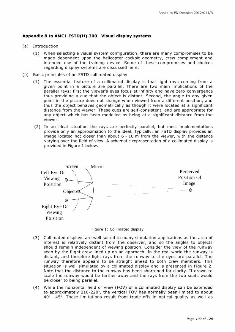
Annex to ED Decision 2012/011/R
Page 109 of 128
Appendix 8 to AMC1 FSTD(H).300 Visual display systems
(a) Introduction
(1) When selecting a visual system configuration, there are many compromises to be made dependent upon the helicopter cockpit geometry, crew complement and intended use of the training device. Some of these compromises and choices regarding display systems are discussed here.
(b) Basic principles of an FSTD collimated display
(1) The essential feature of a collimated display is that light rays coming from a given point in a picture are parallel. There are two main implications of the parallel rays: first the viewer’s eyes focus at infinity and have zero convergence thus providing a cue that the object is distant. Second, the angle to any given point in the picture does not change when viewed from a different position, and thus the object behaves geometrically as though it were located at a significant distance from the viewer. These cues are self-consistent, and are appropriate for any object which has been modelled as being at a significant distance from the viewer.
(2) In an ideal situation the rays are perfectly parallel, but most implementations provide only an approximation to the ideal. Typically, an FSTD display provides an image located not closer than about 6 - 10 m from the viewer, with the distance varying over the field of view. A schematic representation of a collimated display is provided in Figure 1 below.
Figure 1: Collimated display
(3) Collimated displays are well suited to many simulation applications as the area of interest is relatively distant from the observer, and so the angles to objects should remain independent of viewing position. Consider the view of the runway seen by the flight crew lined up on an approach. In the real world the runway is distant, and therefore light rays from the runway to the eyes are parallel. The runway therefore appears to be straight ahead to both crew members. This situation is well simulated by a collimated display and is presented in Figure 2. Note that the distance to the runway has been shortened for clarity. If drawn to scale the runway would be farther away and the rays from the two seats would be closer to being parallel.
(4) While the horizontal field of view (FOV) of a collimated display can be extended to approximately 210-220 , the vertical FOV has normally been limited to about 40 - 45 . These limitations result from trade-offs in optical quality as well as
Left Eye Or
Viewing
Poisit ion
Object
Perceived
Posit ion Of
Image
Mirror
Right Eye Or
Viewing
Poisit ion
Screen
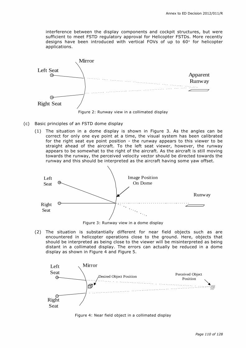
Annex to ED Decision 2012/011/R
Page 110 of 128
interference between the display components and cockpit structures, but were sufficient to meet FSTD regulatory approval for Helicopter FSTDs. More recently designs have been introduced with vertical FOVs of up to 60 for helicopter applications.
Figure 2: Runway view in a collimated display
(c) Basic principles of an FSTD dome display
(1) The situation in a dome display is shown in Figure 3. As the angles can be correct for only one eye point at a time, the visual system has been calibrated for the right seat eye point position - the runway appears to this viewer to be straight ahead of the aircraft. To the left seat viewer, however, the runway appears to be somewhat to the right of the aircraft. As the aircraft is still moving towards the runway, the perceived velocity vector should be directed towards the runway and this should be interpreted as the aircraft having some yaw offset.
Figure 3: Runway view in a dome display
(2) The situation is substantially different for near field objects such as are encountered in helicopter operations close to the ground. Here, objects that should be interpreted as being close to the viewer will be misinterpreted as being distant in a collimated display. The errors can actually be reduced in a dome display as shown in Figure 4 and Figure 5.
Figure 4: Near field object in a collimated display
Left Seat
Right Seat
Apparent
Runway
Mirror
Left
Seat
Right
Seat
Runway
Image Position
On Dome
Left
Seat
Right
Seat
Mirror
Desired Object PositionPerceived Object
Position

Annex to ED Decision 2012/011/R
Page 111 of 128
(3) The FOV possible with a dome display can be larger than that of a collimated display. Depending on the configuration, a FOV of 240 by 90 is possible and can be exceeded.
Figure 5: Near field object in a dome display
(d) Additional display considerations
(1) While the situations described above are for discrete viewing positions, the same arguments can be extended to moving eye points such as are produced by the viewer moving his/her head. In the real world, the parallax effects resulting from head movement provide distance cues. The effect is particularly strong for relative movement of cockpit structure in the near field and modelled objects in the distance. Collimated displays provide accurate parallax cues for distant objects, but increasingly inaccurate cues for near field objects. The situation is reversed for dome displays.
(2) Stereopsis cues resulting from the different images presented to each eye for objects relatively close to the viewer also provide depth cues. Yet again, the collimated and dome displays provide more or less accurate cues depending on the modelled distance of the objects being viewed.
(e) Training implications
(1) In view of the basic principles described above, it is clear that neither display approach provides a completely accurate image for all possible object distances. It is therefore important when configuring an FSTD display system to consider the training role of the FSTD. Depending on the training role, either display may be the optimum choice. Factors which should be considered when selecting a design approach should include relative importance of training tasks at low altitudes, the role of the two crew members in the flying tasks, and the FOV required for specific training tasks.
Left
Seat
Right
Seat
Dome
Desired Object Position
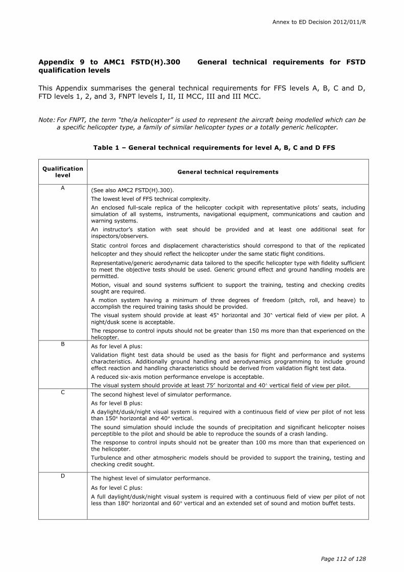
Annex to ED Decision 2012/011/R
Page 112 of 128
Appendix 9 to AMC1 FSTD(H).300 General technical requirements for FSTD
qualification levels
This Appendix summarises the general technical requirements for FFS levels A, B, C and D,
FTD levels 1, 2, and 3, FNPT levels I, II, II MCC, III and III MCC.
Note: For FNPT, the term “the/a helicopter” is used to represent the aircraft being modelled which can be a specific helicopter type, a family of similar helicopter types or a totally generic helicopter.
Table 1 – General technical requirements for level A, B, C and D FFS
Qualification level
General technical requirements
A (See also AMC2 FSTD(H).300).
The lowest level of FFS technical complexity.
An enclosed full-scale replica of the helicopter cockpit with representative pilots’ seats, including simulation of all systems, instruments, navigational equipment, communications and caution and warning systems.
An instructor’s station with seat should be provided and at least one additional seat for inspectors/observers.
Static control forces and displacement characteristics should correspond to that of the replicated
helicopter and they should reflect the helicopter under the same static flight conditions.
Representative/generic aerodynamic data tailored to the specific helicopter type with fidelity sufficient to meet the objective tests should be used. Generic ground effect and ground handling models are permitted.
Motion, visual and sound systems sufficient to support the training, testing and checking credits sought are required.
A motion system having a minimum of three degrees of freedom (pitch, roll, and heave) to accomplish the required training tasks should be provided.
The visual system should provide at least 45 horizontal and 30 vertical field of view per pilot. A
night/dusk scene is acceptable.
The response to control inputs should not be greater than 150 ms more than that experienced on the helicopter.
B As for level A plus:
Validation flight test data should be used as the basis for flight and performance and systems characteristics. Additionally ground handling and aerodynamics programming to include ground effect reaction and handling characteristics should be derived from validation flight test data.
A reduced six-axis motion performance envelope is acceptable.
The visual system should provide at least 75 horizontal and 40 vertical field of view per pilot.
C The second highest level of simulator performance.
As for level B plus:
A daylight/dusk/night visual system is required with a continuous field of view per pilot of not less than 150 horizontal and 40 vertical.
The sound simulation should include the sounds of precipitation and significant helicopter noises perceptible to the pilot and should be able to reproduce the sounds of a crash landing.
The response to control inputs should not be greater than 100 ms more than that experienced on the helicopter.
Turbulence and other atmospheric models should be provided to support the training, testing and checking credit sought.
D The highest level of simulator performance.
As for level C plus:
A full daylight/dusk/night visual system is required with a continuous field of view per pilot of not less than 180 horizontal and 60 vertical and an extended set of sound and motion buffet tests.
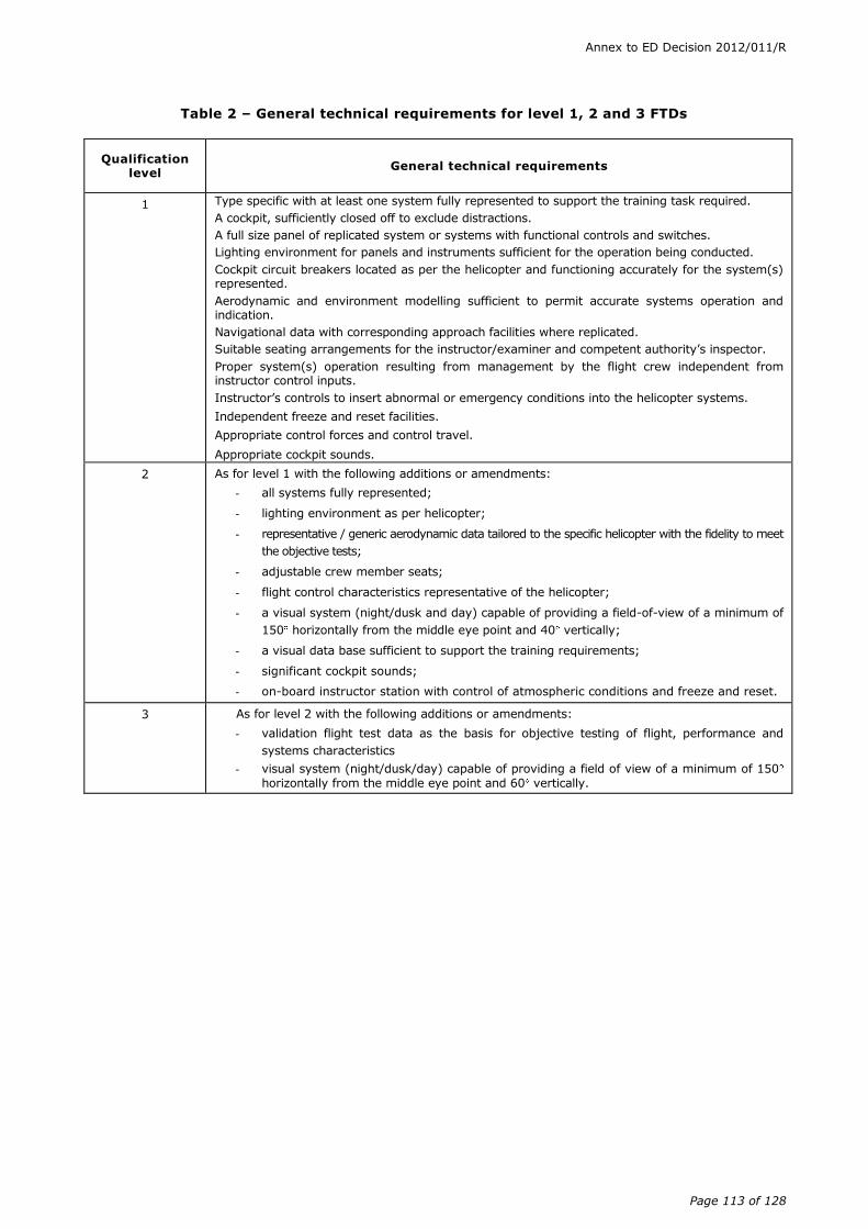
Annex to ED Decision 2012/011/R
Page 113 of 128
Table 2 – General technical requirements for level 1, 2 and 3 FTDs
Qualification level
General technical requirements
1 Type specific with at least one system fully represented to support the training task required.
A cockpit, sufficiently closed off to exclude distractions.
A full size panel of replicated system or systems with functional controls and switches.
Lighting environment for panels and instruments sufficient for the operation being conducted.
Cockpit circuit breakers located as per the helicopter and functioning accurately for the system(s) represented.
Aerodynamic and environment modelling sufficient to permit accurate systems operation and indication.
Navigational data with corresponding approach facilities where replicated.
Suitable seating arrangements for the instructor/examiner and competent authority’s inspector.
Proper system(s) operation resulting from management by the flight crew independent from instructor control inputs.
Instructor’s controls to insert abnormal or emergency conditions into the helicopter systems.
Independent freeze and reset facilities.
Appropriate control forces and control travel.
Appropriate cockpit sounds.
2 As for level 1 with the following additions or amendments:
- all systems fully represented;
- lighting environment as per helicopter;
- representative / generic aerodynamic data tailored to the specific helicopter with the fidelity to meet
the objective tests;
- adjustable crew member seats;
- flight control characteristics representative of the helicopter;
- a visual system (night/dusk and day) capable of providing a field-of-view of a minimum of
150 horizontally from the middle eye point and 40 vertically;
- a visual data base sufficient to support the training requirements;
- significant cockpit sounds;
- on-board instructor station with control of atmospheric conditions and freeze and reset.
3 As for level 2 with the following additions or amendments:
- validation flight test data as the basis for objective testing of flight, performance and
systems characteristics
- visual system (night/dusk/day) capable of providing a field of view of a minimum of 150
horizontally from the middle eye point and 60 vertically.

Annex to ED Decision 2012/011/R
Page 114 of 128
Table 3A - General technical requirements for level I FNPTs
Qualification level
General technical requirements
I The lowest level of FNPT technical complexity.
A cockpit that is sufficiently closed off to exclude distractions, that replicates the helicopter.
Instruments, equipment, panels, systems, primary and secondary flight controls sufficient for the training events to be accomplished should be located in a spatially correct position.
Suitable arrangements for an instructor should be provided allowing an adequate view of the crew members' panels and station.
Effects of aerodynamic and environment changes for various combinations of airspeed and power normally encountered in flight.
Navigation and communication equipment corresponding to that of a helicopter.
Navigational data, including en-route aids and appropriate aerodromes/operating sites, with corresponding approach procedures.
Control forces and control travel should broadly correspond to those of a helicopter.
Appropriate cockpit sounds should be available.
Variable effects of wind and turbulence.
Hard copy of map and approach plot.
Instructor’s controls to insert abnormal or emergency conditions into the basic flight instruments and navigation equipment and to vary environmental conditions.
Independent freeze and reset facilities
Table 3B - General technical requirements for level II FNPTs
Qualification level
General technical requirements
II As for level I with the following additions or amendments: Circuit breakers should function correctly when involved in procedures or malfunctions requiring or involving flight crew response. Crew members’ seats with adequate adjustment. An additional observer seat. Generic ground handling and aerodynamic ground effects models. Systems should be operative to the extent that it should be possible to perform normal, abnormal and emergency operations. Adjustable cloud base and visibility. Control forces and control travels which respond in the same manner under the same flight conditions as in a helicopter. A more complex aerodynamic model. Significant cockpit sounds, responding to pilot actions A daylight/dusk/night visual system is required with a continuous field of view per pilot of not less than 150 horizontal and 40 vertical. A visual data base should be provided sufficient to support the training requirements, including at least:
- specific areas within the database with higher resolution to support landings, take-offs and ground cushion exercises and training away from an aerodrome/operating site; and
- sufficient scene details to allow for ground to map navigation over a sector length equal to 30 minutes at an average cruise speed.
Table 3C - General technical requirements for level III FNPTs
Qualification level
General technical requirements
III
As for level II with the following additions or amendments:
- a daylight, dusk and night visual system is required with a continuous field of view per pilot of not less than 150 horizontal and 60 vertical; and
- detailed high resolution visual data bases as required to support advanced training.

Annex to ED Decision 2012/011/R
Page 115 of 128
Table 3D - General technical requirements for level IIMCC, IIIMCC FNPTs
Qualification level
General technical requirements
II MCC and
III MCC
For use in multi-crew cooperation (MCC) training - as for levels II or III with additional systems, instrumentation and indicators as required for MCC training and operation. Reference Appendix 1 to CS FSTD(H).300.
AMC2 FSTD(H).300 Guidance on design and qualification of level 'A' helicopter full
flight simulators (FFSs)
(a) Background
(1) When determining the cost effectiveness of any FSTD many factors should be taken into account such as:
(i) environmental
(ii) safety
(iii) accuracy
(iv) repeatability
(v) quality and depth of training
(vi) weather and crowded airspace
(2) The requirements as laid down by the various regulatory bodies for the lowest level of FFS do not appear to have been promoting the anticipated interest in the acquisition of lower cost FFS for the smaller helicopter used by the general aviation community.
(3) The significant cost drivers associated with the production of any FSTD are:
(i) type-specific data package
(ii) QTG flight fest data
(iii) motion system
(iv) visual system
(v) flight controls
(vi) aircraft parts
Note: To attempt to reduce the cost of ownership of a level A FFS , each element has been examined in turn and with a view to relaxing the requirements where possible whilst recognising the training, checking and testing credits allowed on such a device.
(b) Data package
(1) The cost of collecting specific flight test data sufficient to provide a complete model of the aerodynamics, engines and flight controls can be significant. In the absence of type-specific data packages the use of a class specific data package that could be tailored to represent a specific type of helicopter is acceptable. This may enable a well-engineered baseline data package to be carefully tuned to adequately represent any one of a range of similar helicopters. Such work including justification and the rationale for the changes would have to be carefully documented and made available for consideration by the Agency as part of the qualification process. Note that for this lower level of FFS, the use of generic ground handling and generic ground effect models is allowed.
Annex to ED Decision 2012/011/R
Page 116 of 128
(2) However, specific flight test data to meet the needs of each relevant test within the QTG should be required. Recognising the cost of gathering such data, the following points should be borne in mind:
(i) For this class of FFS, much of the flight test information could be gathered by simple means e.g. stopwatch, pencil and paper or video. However, comprehensive details of test methods and initial conditions should be presented.
(ii) A number of tests within the QTG have had their tolerances reduced to “correct trend and magnitude” (CT&M) thereby avoiding the need for specific flight test data.
(iii) The use of CT&M is not to be taken as an indication that certain areas of simulation can be ignored. Indeed, in the class of helicopter FSTD envisaged, that might take advantage of level A, it is imperative that the specific characteristics are present, and incorrect effects would be unacceptable (e.g. if the helicopter has a weak positive spiral stability, it would not be acceptable for the FFS to exhibit neutral or negative spiral stability).
(iv) Where CT&M is used, it is strongly recommended that an automatic recording system be used to “footprint” the baseline results thereby avoiding the effects of possible divergent subjective opinions on recurrent evaluations.
(c) Motion
(1) For level A FFS, the requirements for both the primary cueing and buffet simulation have not been specified in detail. Traditionally, for primary cueing, emphasis has been laid on the numbers of axes available on the motion system. For this level of FFS, it is felt appropriate that the FFS manufacturer should be allowed to decide on the complexity of the motion system. However, during the evaluation, the motion system should be assessed subjectively to ensure that it supports the piloting task, including engine failures, and never provides negative cueing.
(2) Buffet simulation is important to add realism to the overall simulation; for level A, the effects can be simple but they should be appropriate, in harmony with the sound cues and never provide negative training.
(d) Visual
(1) Other than field of view (FOV) technical criteria for the visual systems are not specified. The emergence of lower cost ‘raster only’ day light systems is recognised. The adequacy of the performance of the visual system should be determined by its ability to support the flying tasks. e.g. “visual cueing sufficient to support changes in approach path by using runway perspective”.
(2) A single channel direct viewing system would be acceptable for this level of FFS.
(3) The vertical field of view FOV specified (30°) may be insufficient for certain tasks. Some smaller helicopters have large downward viewing angles which cannot be accommodated by the ±15° vertical FOV. This can lead to two limitations:
(i) at the CAT 1 decision height, the appropriate visual ground segment may not be “seen”; and
(ii) during an approach, where the helicopter goes below the ideal approach path, during the subsequent pitch up to recover, adequate visual reference to make a landing on the runway may be lost.
Annex to ED Decision 2012/011/R
Page 117 of 128
(e) Flight controls
The specific requirements for flight controls remain unchanged. Because the handling qualities of smaller helicopters are inextricably intertwined with their flight controls, there is little scope for relaxation of the tests and tolerances. It could be argued that with reversible control systems that the “on ground” static sweep should in fact be replaced by more representative “in air” testing. It is hoped that lower cost control loading systems would be adequate to fulfil the needs of this level of simulation (i.e. electric).
(f) Aircraft parts
As with any level of FSTD, the components used within the cockpit area need not be helicopter parts. However, any parts used should be robust enough to endure the training tasks. Moreover, the level A FFS is type-specific, thus all relevant switches, instruments, controls etc. within the simulated area will be required to look, feel and have the same functionality as in the helicopter.
AMC3 FSTD(H).300 Guidance on design and qualification of helicopter flight training
devices (FTDs)
(a) Basic philosophy
(1) The basic premises in defining FTDs were to follow the prescribed CS-FSTD practices but to reflect the unique training requirements of rotary wing aircraft. It was recognised, from the outset, that the training requirements and the operating/training economics of the average helicopter operator were rather different from those of the majority of fixed wing operators. The helicopter FTD was envisaged as a training device that could be justified both for systems training and secondarily for some type training, testing and checking. Finally, it was accepted that there could not be two differing sets of criteria for the qualification of FSTDs that are approved for type testing & checking. If a technical criterion has been set as the minimum necessary for the type accreditation of a manoeuvre or training event in the FFS, the same criterion shall apply to the FTD in order that a two tier checking philosophy is not introduced.
(2) Following upon these premises, it was decided to define three levels of helicopter FTD.
(3) The FTD level 1 would be to cater only for systems training and would be used by those operators who had helicopters including complex systems. In this role it could be utilised both in ground school technical training as well as operations type training. It would be without motion or visual systems and requires aerodynamic and environmental modelling (using design data that might be generic but tailored to represent the helicopter) of sufficient fidelity to provide accurate systems operation & indications. The validation of the simulation would be confirmed by objective tests designed to meet the training task for the systems for which accreditation was to be sought. The FTD level 1 could prove to be a reasonably inexpensive and cost effective training solution but this level would not necessarily meet the criteria to enable its additional qualification as an FNPT.
(4) The second and third level of FTD were designed to provide type-specific devices with visual systems but no motion which can be offered for varying levels of credits.
(5) The helicopter FTD level 2 would require the use of design & validation data similar to that for FTD level 1 but all systems would have to be represented as well as a visual system meeting the requirements of an FNPT II. The FTD level 2 criteria would permit the device to be used for part of the type rating training syllabus, for recency flying and instrument rating (IR) revalidation.
Annex to ED Decision 2012/011/R
Page 118 of 128
(6) The FTD level 3 would require the use of the same quality of flight test data as the basis for flight & performance and system characteristics and validation flight test data for the objective testing, as is required for a FFS. A visual system meeting the criteria of that fitted to an FNPT III would be the minimum requirement. The FTD level 3 should be capable of being approved for many of the type training, testing & checking manoeuvres and events awarded to a FFS, the exceptions would include those events for which motion cueing is considered necessary.
(b) Design standards
There are three sets of FTD design standards specified within CS-FSTD(H), FTD levels 1, 2 and 3, the most demanding being those for FTD level 3.
(1) The cockpit
The cockpit should be representative of the “helicopter”. The controls, instruments and avionics controllers should be representative in touch, feel, layout, colour and lighting to create a positive learning environment and good transfer of training to the helicopter. For good training ambience the cockpit of the FTD 1 should be sufficiently enclosed to exclude any distractions. For both FTD levels 2 and 3 the cockpit should be fully enclosed. Distractions arising from external sources, which may affect the student’s concentration or that may denigrate the effects of the simulation, should be avoided. Thus in the case of an FTD level 1, if the rear of the device is open, it would be inappropriate to install this type of device in a non-enclosed room or in an area where several such devices are located. Where this is to be permitted, the activities in one device may affect those in an adjacent one. If the device is to be installed in an area shared by other devices then the rear of the cockpit including the instructors’ station, should be fully enclosed, and this enclosure should extend to include the roof. In the case of FTD levels 2 and 3 the same interpretations should apply but an additional consideration is that the performance of the visual system will be adversely affected by any light ingress or reflections. It follows that it would not be necessary to have a fully enclosed structure at the rear of the cockpit were the FTD to be installed in a separate room.
(2) Cockpit components
As with any training device, the components used within the cockpit area do not need to be helicopter parts. However, any parts used should be representative and should be robust enough to endure the training tasks. The use of CRTs or “flat panel” displays with physical overlays incorporating operational switches/knobs/buttons replicating a helicopter instrument panel would be acceptable. The training tasks envisaged for these devices are such that appropriate layout and feel is very important: i.e. the altimeter sub-scale knob needs to be physically located on the altimeter.
(c) Latency and visual
(1) There are two methods of establishing latency, which is the relationship between the controls and the visual system, cockpit instruments response and initial motion system response, if fitted. These should be coupled closely to provide integrated sensory cues.
(2) Either transport delay or response time tests are acceptable. Response time tests check that the response to abrupt pitch, roll, and yaw inputs at the pilot ’s position is within the permissible delay, but not before the time when the helicopter would respond under the same conditions. Visual scene changes from steady state disturbance should occur within the system dynamic response limit (but not before the resultant motion onset if fitted).
(3) The transport delay test should measure all the delay encountered by a step signal migrating from the pilot’s control through the control loading electronics
Annex to ED Decision 2012/011/R
Page 119 of 128
(if applicable) and interfacing through all the simulation software modules in the correct order, using a handshaking protocol, finally through the normal output interfaces to the visual system and instrument displays. A recordable start time for the test should be provided by a pilot flight control input. The test mode should permit normal computation time to be consumed and should not alter the flow of information through the hardware/software system.
(4) The transport delay of the system is the time between control input and the individual hardware responses. It need only be measured once in each axis.
(d) Motion
Although motion is not a requirement for an FTD, should the FSTD operator choose to have one fitted, it should be evaluated to ensure that its contribution to the overall fidelity of the device is not negative. Unless otherwise stated in this document, the motion requirements are as specified for a level A FFS, see AMC2 FSTD(H).300.
(1) For level A FFSs, the requirements for both the primary cueing and buffet simulation have been not specified in detail. Traditionally, for primary cueing, emphasis has been laid on the numbers of axes available on the motion system. For this level of FFS, it is felt appropriate that the simulator manufacturer should be allowed to decide on the complexity of the motion system. However, during the evaluation, the motion system should be assessed subjectively to ensure that it is supporting the piloting task, including engine failures, and is in no way providing negative cueing.
(2) Buffet simulation is important to add realism to the overall simulation; for level A, the effects can be simple but they should be appropriate, in harmony with the sound cues and in no way providing negative training.
(3) The motion system transport delay should meet the standards prescribed for the visual display and cockpit instrument response.
(e) Testing/evaluation
(1) To ensure that any device meets its design criteria initially and periodically throughout its life a system of objective and subjective testing will be used. The subjective and objective testing methodology should be similar to that in use for FFS.
(2) The validation tests specified under AMC1 FSTD(H).300, paragraph (b), can be “flown” by a suitably skilled person and the results recorded manually. Bearing in mind the cost implications, the use of automatic recording (and testing) is encouraged, thereby increasing the repeatability of the achieved results.
(3) The tolerances specified are designed to ensure that the device meets its original target criteria year after year. It is therefore important that any such target data are carefully derived and values are agreed with the competent authority in advance of any formal qualification process.
(4) The use of CT&M is not to be taken as an indication that certain areas of simulation can be ignored. For such tests, the performance of the device should be appropriate and representative of the helicopter configuration and should under no circumstances exhibit negative characteristics. Where CT&M is used, it is strongly recommended that an automatic recording system be used to "footprint" the baseline results thereby avoiding the effects of possible divergent subjective opinions during recurrent evaluations.
(5) The subjective tests listed under “Functions and manoeuvres” in AMC1 FSTD(H).300, paragraph (c), should be flown out by a suitably qualified and experienced pilot. Subjective testing should review not only the interaction of all of the systems but the integration of the FTD with:
(i) the training environment,
(ii) freezes and repositions,

Annex to ED Decision 2012/011/R
Page 120 of 128
(iii) nav-aid environment,
(iv) communications,
(v) weather and visual scene contents.
In parallel with this objective/subjective testing process it is envisaged that suitable maintenance arrangements as part of a compliance monitoring programme shall be in place. Such arrangements should cover routine maintenance, the provision of satisfactory spares holdings and personnel and may be subject to a regulatory audit.
(f) Additional features
(1) Any additional features in excess of the minimum design requirements added to any FTD level 1, 2 and 3 should be subject to evaluation and should meet the appropriate standards in CS-FSTD(H).
AMC4 FSTD(H).300 Use of data for helicopter flight training devices (FTDs)
(a) Two types of data are required for the development and qualification of an FSTD; namely, design data, which are used to develop simulation models, and the second, termed validation data, which are used to objectively confirm that the simulation models reflect the static as well as the dynamic performance characteristics of the helicopter. Some levels of FTD to be qualified under CS-FSTD(H) require that their design data be based upon helicopter type-specific data and/or that the validation tests have a similar baseline. It is not always intended that such design and validation data must be the helicopter manufacturer’s flown test data in the same manner as are required for FFS. Whilst this is the preferred source, cost and availability can preclude their use. Acceptable alternatives can be data obtained from research laboratories or other data procurement agencies and companies as well as preliminary data from a helicopter manufacturer’s engineering simulator.
(b) For the FTD level 1 & 2 much of the flight test data could be gathered from helicopter maintenance, performance, flight manuals, and system user guides supplemented by data gathered and recorded, in flight, by simple means, e.g. video, stopwatch, pencil & paper. However for the latter, comprehensive details of test methods and initial and ambient conditions should be presented. In addition, this data may also be supplemented with theoretically calculated results.
(c) For FTD level 3 it is necessary to use validation flight test data, such as is required for higher level FFS but limited only to the validation of flight, performance, handling qualities and systems characteristics.
(d) The substitution of CT&M for defined tolerances also reduces the reliance upon specific flight test data, but this must not be taken as an indication that certain areas of simulation can be ignored. It is imperative that the specific characteristics of the helicopter are present and incorrect effects would be unacceptable.
(e) The Agency expects any FTD manufacturer who wishes to take advantage of the use of an alternative type of data to helicopter manufacturer’s flown data, to demonstrate a sound engineering basis for his/her proposed approach. Such demonstration should show the predicted simulation effects and that they are easily understood and defined. The Agency will constitute a team to review any applications for the substitution of data other than that of the helicopter manufacturer’s flown data.
AMC5 FSTD(H).300 Guidance on design and qualification of helicopter flight and
navigation procedures trainers (FNPTs)
(a) Basic philosophy
(1) Traditionally training devices used by the ab-initio professional pilot schools have been relatively simple instrument flight-only aids. These devices were loosely based on the particular school’s helicopter. The performance would be
Annex to ED Decision 2012/011/R
Page 121 of 128
approximately correct in a small number of standard configurations; however, the handling characteristics could range from rudimentary to loosely representative. The instrumentation and avionics fit varied between a basic fit and one very close to the target helicopter. The approval to use such devices as part of a training course was based on a regular subjective evaluation of the equipment and its operator by an inspector of the competent authority.
(2) The FNPT I is essentially a replacement for the traditional instrument flight ground training device. The FNPT II and FNPT III are more sophisticated standards and each fulfil the wider requirements of the various Part-FCL professional pilot training modules up to and including (optionally with additional features) multi-crew cooperation (MCC) training.
(3) The currently available technology enables such devices to have much greater capabilities and lower life-cycle costs than was previously possible. A more objective design basis encourages better understanding and therefore better modelling of helicopter systems, handling and performance. These advances combined with the costs of flying and with the environmental pressures all point towards the need for FNPT standards.
(b) Design standards
Five sets of design standards are specified within CS-FSTD(H): FNPT I, II, II MCC, III and III MCC.
(1) Simulated helicopter configuration
Unlike FFSs and FTDs, FNPTs are not primarily intended to be representative of a specific type of helicopter (although they may in fact be type-specific if desired).
The configuration chosen should sensibly represent the helicopter or helicopters likely to be used as part of the overall training package. Areas such as general layout, seating, instruments and avionics, control type, control force and position, performance and handling and powerplant configuration should be representative of the class of helicopters or the helicopter itself.
Note: throughout this document, the term “helicopter” is used to represent the aircraft being modelled which can be a specific helicopter type, a family of similar helicopter types or a totally generic helicopter.
It would be beneficial for all parties involved in the acquisition of an FNPT to engage in early discussions with the competent authority to broadly agree a suitable device configuration. Ideally, any such discussion would take place in time to avoid any delays in the design/build/acceptance process thereby ensuring a smooth entry into service.
The configuration chosen should be sensibly representative of the “helicopter” likely to be used as part of the overall training package, especially in areas such as general cockpit layout, seating, instruments and avionics, flying controls control forces and positions, performance, handling and powerplant.
(2) The cockpit
The cockpit should be representative of the “helicopter”. The controls, instruments and avionics controllers should be representative in touch, feel, layout, colour and lighting to create a positive learning environment and good transfer of training to the helicopter. For good training ambience the cockpit of the FNPT I should be sufficiently enclosed to exclude any distractions. For both FNPT IIs and IIIs the cockpit should be fully enclosed. Distractions arising from external sources, which may affect the student’s concentration or may denigrate the effects of the simulation, should be avoided. Thus in the case of an FNPT I, if the rear of the device is open, it would be inappropriate to install this type of device in a non-enclosed room or in an area where several such devices are located. Were this to be permitted, the activities in one device may affect those

Annex to ED Decision 2012/011/R
Page 122 of 128
in an adjacent one. If the device is to be installed in an area shared by other devices then the rear of the cockpit including the instructor’s station should be fully enclosed, and this enclosure should extend to include the roof. In the case of the FNPT II and III the same interpretations should apply but an additional consideration is that the performance of the visual system will be adversely affected by any light ingress or reflections. It follows that it would not be necessary to have a fully enclosed structure at the rear of the cockpit were the FNPT to be installed in a separate room.
(3) Cockpit components
As with any training device, the components used within the cockpit area do not need to be aircraft parts; however, any parts used should be representative and should be robust enough to endure the training tasks. With the current state of technology the use of simple CRT/LCD monitor-based representations and touch screen controls would be acceptable. The training tasks envisaged for these devices are such that appropriate layout and feel is very important: i.e. the altimeter sub-scale knob needs to be physically located on the altimeter.
The use of CRT/LCDs with physical overlays incorporating operational switches/knobs/buttons replicating a helicopter instrument panel may be acceptable to the competent authority.
(4) Data
The data used to model the aerodynamics, flight controls and engines should be soundly based on a helicopter. It is not acceptable and would not give good training if the models merely represented a few key configurations bearing in mind the extent of the potential credits available. Validation data may be derived from a specific helicopter within a family of helicopters that the FNPT is intended to represent, or it may be based on information from several helicopters within a family. It is recommended that the intended validation data together with a substantiation report be submitted to the competent authority for review.
(i) Data collection and model development
Recognising the cost and complexity of flight simulation models, it should be possible to generate generic family “typical” models. Such models should be continuous and vary sensibly throughout the required training flight envelope. A basic requirement for any modelling is the integrity of the mathematical equations and models used to represent the flying qualities and performance of the designated helicopter configuration simulated. Data to tune the generic model to represent a more specific helicopter can be obtained from many sources without recourse to expensive flight test such as:
(A) helicopter design data;
(B) flight and maintenance manuals; or
(C) observations on ground and in air.
Data obtained on the ground and in flight can be measured and recorded using a range of simple means such as:
(A) video;
(B) pencil and paper;
(C) stopwatch;
(D) new technologies.
Any such data gathering should take place at representative masses and centres of gravity. Development of such a data set including justification and the rationale for the design and intended performance, the
Annex to ED Decision 2012/011/R
Page 123 of 128
measurement methods and recorded parameters (e.g. mass, CG, atmospheric conditions) should be carefully documented and available for inspection by the competent authority as part of the qualification process.
(5) Limitations
In helicopters, varied and different flight control configurations can be found: with and without servo-control assistance, with and without artificial feel trim control forces, trim control release and automatic trim. As a consequence, simulation of the flight control forces should take into account user requirements in order to define the optimum solution in an effort to simplify the control loading requirements.
It should be remembered however that whilst a simple model may be sufficient for the task, it is vitally important that negative characteristics are not present .
(c) Latency and visual
(1) There are two methods of establishing latency, which is the relationship between the controls and the visual system, cockpit instruments response and initial motion system response, if fitted. These should be coupled closely to provide integrated sensory cues.
(2) For a generic FNPT, a transport delay test is the only suitable test which demonstrates that the FNPT system does not exceed the permissible delay. If the FNPT is based upon a particular helicopter type, either transport delay or response time tests are acceptable. Response time tests check that the response to abrupt pitch, roll, and yaw inputs at the pilot's position is within the permissible delay, but not before the time when the “helicopter” would respond under the same conditions. Visual scene changes from steady state disturbance should occur within the system dynamic response limit (but not before the resultant motion onset if fitted).
(3) The transport delay test should measure all the delay encountered by a step signal migrating from the pilot’s control, through the control loading electronics (if applicable) and interfacing through all the simulation software modules in the correct order, using a handshaking protocol, finally through the normal output interfaces to the visual system and instrument displays. A recordable start time for the test should be provided by a pilot flight control input. The test mode should permit normal computation time to be consumed and should not alter the flow of information through the hardware/software system.
(4) The transport delay of the system is the time between control input and the individual hardware responses. It needs only to be measured once in each axis.
(5) Care should be taken when using the limited processing power of the lower cost visual systems to concentrate on the key areas that support the intended uses, thereby avoiding compromising the visual model by including unnecessary features e.g. moving ground traffic, marshallers. The capacity of the visual model should be directed towards:
(i) runway/operating site surface;
(ii) runway/operating site lighting systems;
(iii) approach guidance aids and lighting systems;
(iv) touch down and lift-off (TLOF) and final approach and take-off (FATO) areas;
(v) detailed ground features where credits are required for navigation training; and
(vi) basic environmental lighting (night/dusk).
(d) Motion

Annex to ED Decision 2012/011/R
Page 124 of 128
Although motion is not a requirement for an FNPT, should the FSTD operator choose to have one fitted, it should be evaluated to ensure that its contribution to the overall fidelity of the device is not negative. Unless otherwise stated in this document, the motion requirements are as specified for a level A FFS, see AMC2 FSTD(H).300.
(1) For level A FFSs, the requirements for both the primary cueing and buffet simulation have been not specified in detail. Traditionally, for primary cueing, emphasis has been laid on the numbers of axes available on the motion system. For this level of FFS, it is felt appropriate that the simulator manufacturer should be allowed to decide on the complexity of the motion system. However, during the evaluation, the motion system should be assessed subjectively to ensure that it is supporting the piloting task, including engine failures, and is in no way providing negative cueing.
(2) Buffet simulation is important to add realism to the overall simulation; for level A, the effects can be simple but they should be appropriate, in harmony with the sound cues and in no way providing negative training.
(3) The motion system transport delay should meet the standards prescribed for the visual display and cockpit instrument response.
(e) Testing/evaluation
(1) General
The FNPT should be assessed in those areas that are essential to completing the pilot training, testing and checking process. This includes the FNPT's longitudinal and lateral directional responses, specific operations, control checks, cockpit, and instructor station functions checks, and certain additional requirements depending on the complexity or qualification level of the FNPT. The visual system (where applicable) should be evaluated against tests contained in the table of validation tests (AMC1 FSTD(H).300).
To ensure that any device meets its design criteria, initially and periodically throughout its life a system of objective and subjective testing should be used. The subjective and objective testing methodology should be similar to that in use for FFS.
The validation tests specified (AMC1 FSTD(H).300, (b)(3)) can be “flown” by a suitably skilled person and the results recorded manually. Bearing in mind the cost implications, the use of automatic recording (and testing) is encouraged thereby increasing the repeatability of the achieved results but any such automatic test shall be capable of being rerun by manually flying the test.
The tolerances specified are designed to ensure that the device meets its original target criteria year after year. It is therefore important that such target data is carefully derived and values are agreed with the appropriate inspecting authority in advance of any formal qualification process. For initial qualification, it is highly desirable that the device should meet its design criteria within the listed tolerances, however unlike the tolerances specified for FFS, the tolerances contained within this document are specifically intended to be used to ensure repeatability during the life of the device and in particular at each recurrent regulatory inspection.
(2) Validation tests
The intent is to evaluate the FNPT as objectively as possible. Pilot acceptance, however, is also an important consideration. Therefore, the FNPT should be subjected to validation, and functions and subjective tests listed in (AMC1 FSTD(H).300). Validation tests are used to compare objectively FNPT performances against validation data to ensure that they agree within design tolerances acceptable to the competent authority. Functions and subjective tests provide a basis for evaluating FNPT capability to perform over a typical training
Annex to ED Decision 2012/011/R
Page 125 of 128
period, determining that the FNPT satisfactorily meets each stated training objective and competently simulates each training manoeuvre or procedure and to verify correct operation of the FNPT.
The design data may be derived from flight test data, manufacturer’s design data, information from an aircraft flight manual and maintenance manuals, results of approved or commonly accepted simulations or predictive models, recognised theoretical results, information from the public domain, or other sources as deemed necessary by the FNPT manufacturer to be representative of a helicopter.
The use of CT&M is not to be taken as an indication that certain areas of simulation can be ignored. For such tests, the performance of the device should be appropriate and representative of the “helicopter” configuration and should under no circumstances exhibit negative characteristics. Where CT&M is used, it is strongly recommended that an automatic recording system be used to "footprint" the baseline results thereby avoiding the effects of possible divergent subjective opinions during recurrent evaluations.
(3) Subjective tests
The subjective tests listed under “Functions and subjective tests” (AMC1 FSTD(H).300) should be flown out by a suitably qualified and experienced pilot.
Subjective testing should review not only the interaction of all of the systems but the integration of the FNPT with:
(i) the training environment;
(ii) freezes and repositions;
(iii) nav-aid environment;
(iv) communications;
(v) weather and visual scene contents.
(4) Initial qualification
For initial qualification testing of FNPTs validation data should be used. They may be derived from a specific helicopter or they may be based on information from several helicopters within the group of helicopters. The substantiation of the set of data used to build the validation data should be in the form of an engineering report and should show that the proposed validation data are representative of a helicopter. With the concurrence of the competent authority, it may be in the form of a manufacturer’s previously approved set of validation data for the applicable FNPT. Once the set of data for a specific FNPT has been accepted and approved by the competent authority, it should become the validation data to be used as reference for subsequent recurrent evaluations.
For FNPT initial qualification, the tolerances listed for parameters in the validation list table (AMC1 FSTD(H).300) should be replaced by ‘correct trend and magnitude’ (CT&M) and the FNPT should be tested and assessed as representative of a helicopter to the satisfaction of the competent authority.
Tolerances listed for parameters in the validation tests table (AMC1 FSTD(H).300) should not be confused with FNPT design tolerances. Validation test tolerances are the maximum acceptable for FNPT recurrent qualification testing.
FSTD operators seeking initial or upgrade evaluation of an FNPT should be aware that performance and handling data for older helicopters may not be of sufficient quality to meet some of the test standards contained in this AMC. In this
Annex to ED Decision 2012/011/R
Page 126 of 128
instance it may be necessary for an FSTD operator to acquire additional design and/or validation data.
During FNPT evaluation, if a problem is encountered with a particular FSTD validation test, the test may be repeated to ascertain if the problem was caused by test equipment or FSTD operator error. Following this, if the test problem persists during initial FNPT evaluation, an FSTD operator should be prepared to offer alternative test results which relate to the test in question.
Validation tests that do not meet the test criteria should be addressed to the satisfaction of the competent authority.
(5) Maintenance
In parallel with this objective/subjective testing process it is envisaged that suitable maintenance arrangements as part of a compliance monitoring programme should be in place. Such arrangements should cover routine maintenance, the provision of satisfactory spares holdings and personnel and may be subject to a regulatory audit.
(f) Additional features
Any additional features in excess of the minimum design requirements added to an FNPT I, II & III should be subject to evaluation and should be assessed to avoid negative training.
AMC6 FSTD(H).300 Engineering simulator validation data
(a) When a fully flight test validation simulation is modified as a result of changes to the simulated helicopter configuration, a qualified helicopter manufacturer may choose, with the prior agreement of the competent authority, to supply validation data from an “audited” engineering simulator/simulation to supplement selectively flight test data. This arrangement is confined to changes that are incremental in nature and are both easily understood and well defined.
(b) To be qualified to supply engineering simulator validation data, a helicopter manufacturer should:
(1) have a proven track record of developing successful data packages;
(2) have demonstrated high quality prediction methods through comparisons of predicted and flight test validated data;
(3) have an engineering simulator that:
- has models that run in an integrated manner;
- uses the same models as released to the training community (which are also used to produce stand/alone proof-of-match and checkout documents);
- is used to support helicopter development and certification;
(4) use the engineering simulation to produce a representative set of integrated proof-of-match cases; and
(5) have an acceptable configuration control system in place covering the engineering simulator and all other relevant engineering simulations.
(c) Helicopter manufacturers seeking to take advantage of this alternative arrangement should contact the competent authority at the earliest opportunity.
(d) For the initial application, each applicant should demonstrate his/her ability to qualify to the satisfaction of the Agency, in accordance with the criteria in this AMC and the corresponding AMC7 FSTD(H).300.
AMC7 FSTD(H).300 Engineering simulator validation data – approval guidelines
Annex to ED Decision 2012/011/R
Page 127 of 128
(a) Background
(1) In the case of fully flight test validated simulation models of a new or major derivative aircraft, it is likely that these models will become progressively unrepresentative as the aircraft configuration is revised.
(2) Traditionally as the aircraft configuration has been revised, the simulation models have been revised to reflect changes. In the case of aerodynamic, engine, flight control and ground handling models, this revision process normally results in the collection of additional flight test data and the subsequent release of new models and validation data.
(3) The quality of the prediction of simulation models has advanced to the point where differences between the predicted and the flight test validation models are often quite small.
(4) The major aircraft manufacturers utilise the same simulation models in their engineering simulations as released to the training community. These simulations vary from physical engineering simulators with and without aircraft hardware to non-real-time work station based simulations.
(b) Approval guidelines – for using engineering simulator validation data
(1) The current system of requiring flight test data as a reference for validating training simulators should continue.
(2) When a fully flight test-validated simulation is modified as a result of changes to the simulated aircraft configuration, a qualified aircraft manufacturer may choose, with prior agreement of the competent authority, to supply validation data from an engineering simulator/simulation to supplement selectively flight test data.
(3) In cases where data from an engineering simulator is used, the engineering simulation process would have to be audited by the competent authority.
(4) In all cases a data package verified to current standards against flight test should be developed for the aircraft “entry-into-service” configuration of the baseline aircraft.
(5) Where engineering simulator data are used as part of a QTG, an essential match is expected as described in Appendix 1 to AMC1 FSTD(H).300.
(6) In cases where the use of engineering simulator data is envisaged, a complete proposal should be presented to the appropriate competent authorities. Such a proposal would contain evidence of the aircraft manufacturer’s past achievements in high fidelity modelling.
(7) The process should be applicable to “one step” away from a fully flight validated simulation.
(8) A configuration management process should be maintained, including an audit trail that clearly defines the simulation model changes step by step away from a fully flight validated simulation, so that it would be possible to remove the changes and return to the baseline (flight validated) version.
(9) Competent authorities should conduct technical reviews of the proposed plan and the subsequent validation data to establish acceptability of the proposal.
(10) The procedure should be considered complete when an approval statement is issued. This statement should identify acceptable validation data sources.
(11) To be admissible as an alternative source of validation data an engineering simulator should:
(i) have to exist as a physical entity, complete with a cockpit representative of the affected class of aircraft, with controls sufficient for manual flight;
Annex to ED Decision 2012/011/R
Page 128 of 128
(ii) have a visual system; and preferably also a motion system;
(iii) where appropriate, have actual avionics boxes interchangeable with the equivalent software simulations, to support validation of released software;
(iv) have a rigorous configuration control system covering hardware and software; and
(v) have been found to be a high fidelity representation of the aircraft by the pilots of the manufacturers, operators and the competent authority.
(12) The precise procedure followed to gain acceptance of engineering simulator data will vary from case-to-case between aircraft manufacturers and type of change. Irrespective of the solution proposed, engineering simulations/simulators should conform to the following criteria:
(i) the original (baseline) simulation models should have been fully flight test validated;
(ii) the models as released by the aircraft manufacturer to the industry for use in training FSTDs should be essentially identical to those used by the aircraft manufacturer in their engineering simulations/simulators; and
(iii) these engineering simulation/simulators should have been used as part of the aircraft design, development and certification process.
(13) Training FSTDs utilising these baseline simulation models should be currently qualified to at least internationally recognised standards.
(14) The type of modifications covered by this alternative procedure should be restricted to those with “well-understood effects”:
(i) software (e.g. flight control computer, autopilot, etc.);
(ii) simple (in aerodynamic terms) geometric revisions (e.g. body length);
(iii) engines;
(iv) control system gearing, rigging, deflection limits;
(v) brake, tyre and steering revisions.
(15) The manufacturer, who wishes to take advantage of this alternative procedure, is expected to demonstrate a sound engineering basis for his/her proposed approach. Such analysis would show that the predicted effects of the change(s) were incremental in nature and both were easily understood and well defined, confirming that additional flight test data were not required. In the event that the predicted effects were not deemed to be sufficiently accurate, it might be necessary to collect a limited set of flight test data to validate the predicted increments.
(16) Any applications for this procedure should be reviewed by a team established by the Agency.