ETSN01 Advanced Telecommunication
49
Lund University / Presentation 2012 ETSN01 Advanced Telecommunication Network Constructs, Paradigms and shifts
Transcript of ETSN01 Advanced Telecommunication

Lund University /
Presentation 2012
ETSN01
Advanced
Telecommunication
Network Constructs,
Paradigms
and shifts

Lund University /
Presentation 2012
Two ways of building networks
Licensed vs. Unlicensed Spectrum
Licensed Spectrum
• Solution for QoS sensitive
applications
• Exclusive right to spectrum
use
• Network engineering possible
– Predictability
– manageability
• Complex and costly systems
• For big players
Unlicensed Spectrum
• Inherent best effort systems
• “Some” QoS support possible
• No right to use spectrum
- Competition
- Collaboration
• Simple and cheap systems
• For small / medium players

Lund University /
Presentation 2012
Unlicensed Spectrum
• We will look at cellular networks later let’s start with unlicensed
spectrum constructs.
• Today, almost all spectrum licensed and controlled by authority (PTS
in Sweden, FCC in the US etc.)
• Some bands are available for unlicensed use around the world, most
common bands, ISM bands
– 2.4, 5.8, 24.1 GHz common
• Philosophy: equipment must operate in a manner so as to allow co-
existence
• A set of rules regulates equipment operation e.g. output power, use
of spread spectrum

Lund University /
Presentation 2012
The fall of the link paradigm
• Link paradigm migrated from fixed networks
• often used to model and describe wireless networks as well (wireless
links)
• Can fail miserably
• Consider the most basic case:
• two APs, one STA each
• single omnidirectional antennae
• constant output power
• no path loss
• no fading, shadowing etc.

Lund University /
Presentation 2012
This?
Lund University /
Presentation 2012
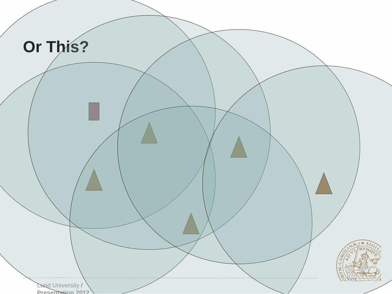
Or This?
Lund University /
Presentation 2012
Topological Links vs. spatial graphs
In fixed networks:
• “Links” are independent entities that may be connected through
routers/switches
• The properties of a single link does not affect other links properties
– apart from the traffic distribution shaping etc.
In broadcast based wireless networks:
• Transceivers cover an area
• other transceivers within area affected, dependencies
• overlap in coverage - dependency
Lund University /
Presentation 2012
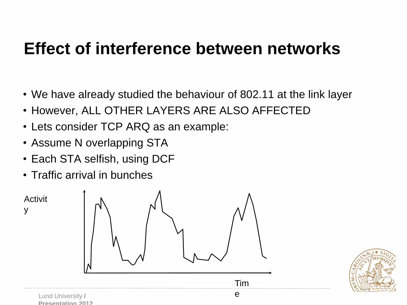
Effect of interference between networks
• We have already studied the behaviour of 802.11 at the link layer
• However, ALL OTHER LAYERS ARE ALSO AFFECTED
• Lets consider TCP ARQ as an example:
• Assume N overlapping STA
• Each STA selfish, using DCF
• Traffic arrival in bunches
Activit
y
Tim
e
Lund University /
Presentation 2012
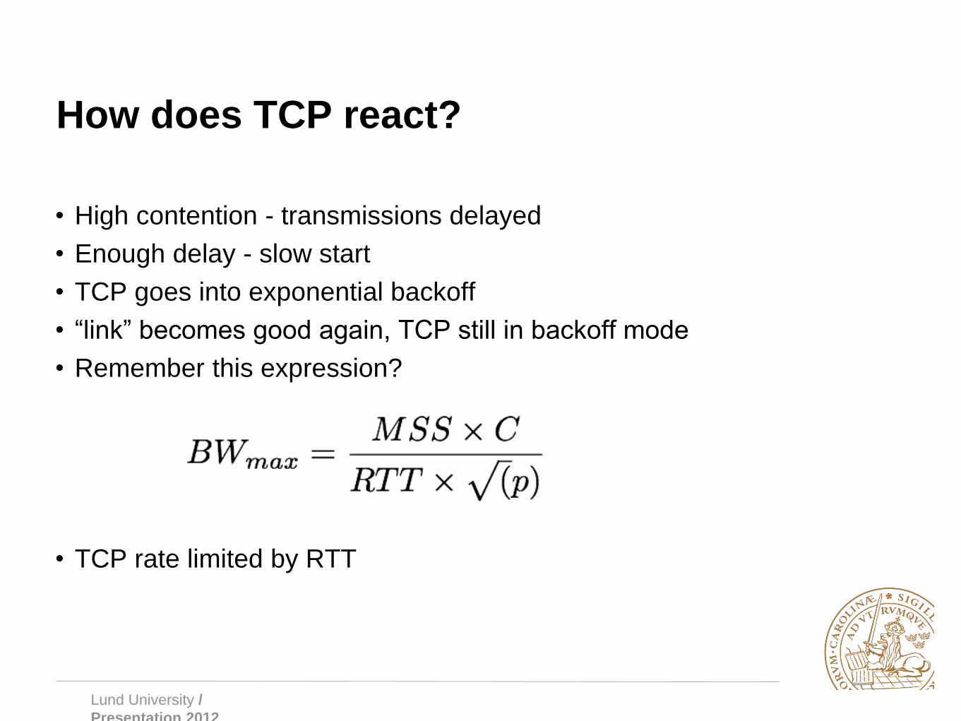
How does TCP react?
• High contention - transmissions delayed
• Enough delay - slow start
• TCP goes into exponential backoff
• “link” becomes good again, TCP still in backoff mode
• Remember this expression?
• TCP rate limited by RTT

Lund University /
Presentation 2012
Why is TCP so heavily affected?
• TCP congestion control is aggressive
– Backoff exponential
• Queue length increase also exponential
– Assume two contending wireless
stations
– Poisson arrivals of traffic
– linear increase in traffic means:
• i.e. exponential delay increase
compounded by TCP exp. backoff
• Old known problem with TCP congestion
control.

Lund University /
Presentation 2012
Antenna sectorisation
• Common strategy in wireless to use directional antennas
– Avoid overlap and contention
– Almost exclusively for fixed installations
– mobility tracking inherently difficult in small cells with highly
varying path characteristics
• Possible to create point to point links that really behave like “links”

Lund University /
Presentation 2012
Ad hoc networks
• Sometimes infrastructure not needed, available, desired
– Ad hoc = spontaneous network formation, as needed
– self configuration ability
• addressing
• routing / forwarding
– Can also be used to extend infrastructure in mixed mode

Lund University /
Presentation 2012
Ad hoc Networks
Problems / challenges
• Lack of infrastructure also brings
– fully distributed solutions (no central coordination)
• Mobility / instability of topology and connectivity
• Energy constraints

Lund University /
Presentation 2012
Use cases
• Disaster recovery
– No infrastructure working
• Developing areas
– No infrastructure available
• PANs (Bluetooth)
• WSN
• VANET
• ...

Lund University /
Presentation 2012
Wireless Sensor Networks (WSN)
• Small battery operated sensors with wireless capability
• deployed in:
– nature (bio monitoring)
– farms (agricultural monitoring)
– industry (process monitoring)
– Warehouses/ships/trucks (asset monitoring)
– etc.
• ad-hoc capabilities spontaneous routing formation
• biggest issue: energy conservation

Lund University /
Presentation 2012
WSN strategies
• Routing based on phy. layer constraints
– connectivity
– coverage
– residual energy
– energy usage (multihop or single high power Tx)
• Scalability and complexity important issues
– Common strategy, clustering

Lund University /
Presentation 2012
Mesh networks
• Multi hop wireless backbone network with wireless access
• Cheap alternative (equipment cheap)
• Very similar to MANET but backbone has low mobility
– routing paths more stable
• Can be combined with gateways to the Internet
Lund University /
Presentation 2012
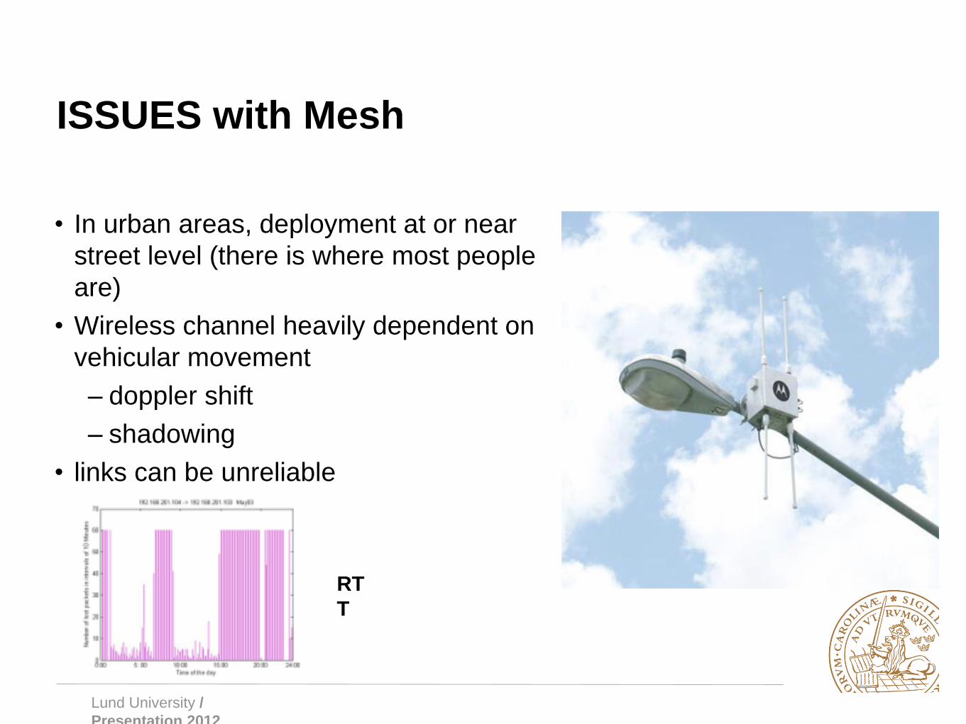
ISSUES with Mesh
• In urban areas, deployment at or near
street level (there is where most people
are)
• Wireless channel heavily dependent on
vehicular movement
– doppler shift
– shadowing
• links can be unreliable
RT
T
Lund University /
Presentation 2012
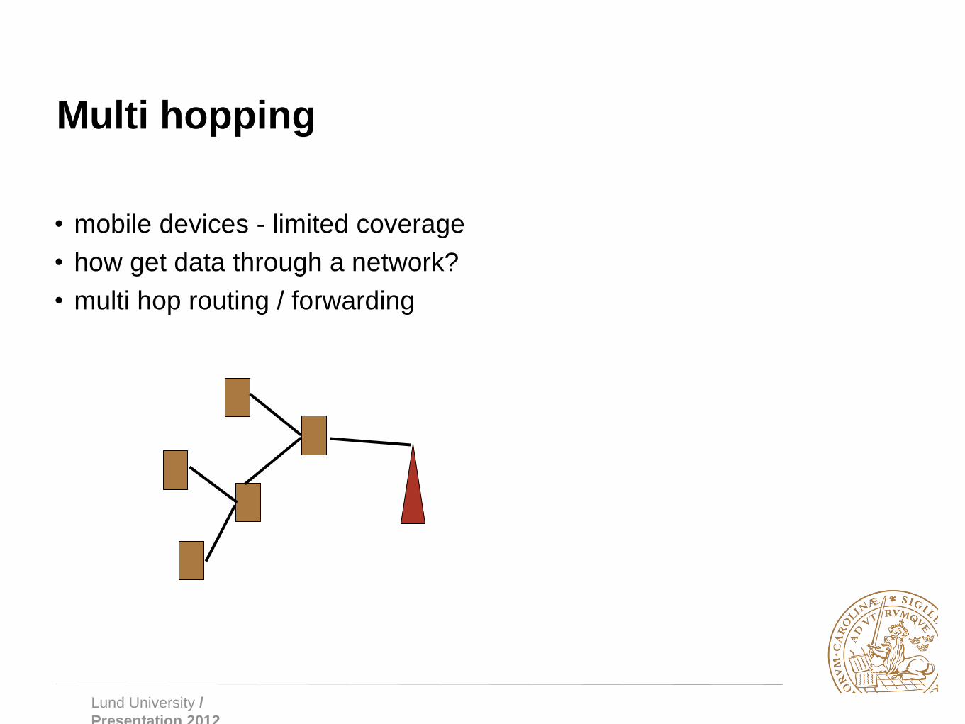
Multi hopping
• mobile devices - limited coverage
• how get data through a network?
• multi hop routing / forwarding

Lund University /
Presentation 2012
Routing
• Mobility causes paths to be unstable
• Using “traditional” shortest path algorithms inefficient
– Dijkstra, Bellman-Ford etc.
• Two main approaches
• Proactive
– Continuously update about topology and changes
– good: low latency, bad: costly updates
• Reactive
– Only determine routing path when sending data
– good: no constant overhead, bad: delay due to route discovery

Lund University /
Presentation 2012
Example, Ad-Hoc On Demand Distance
Vector Routing (AODV)
• Sender broadcasts a Route request packet
– flooded throughout the network
• Nodes maintain route cache, use destination sequence number for
each route entry
• state installed in nodes per destination
• only reacts when routes fail
– try local recovery (nodes monitor neighbours, issue error message
on detected problem)
– sender repeats route discovery
• Cost directly related to rate of mobility, only works for smaller
networks with limited mobility
• currently popular in deployed systems
Lund University /
Presentation 2012
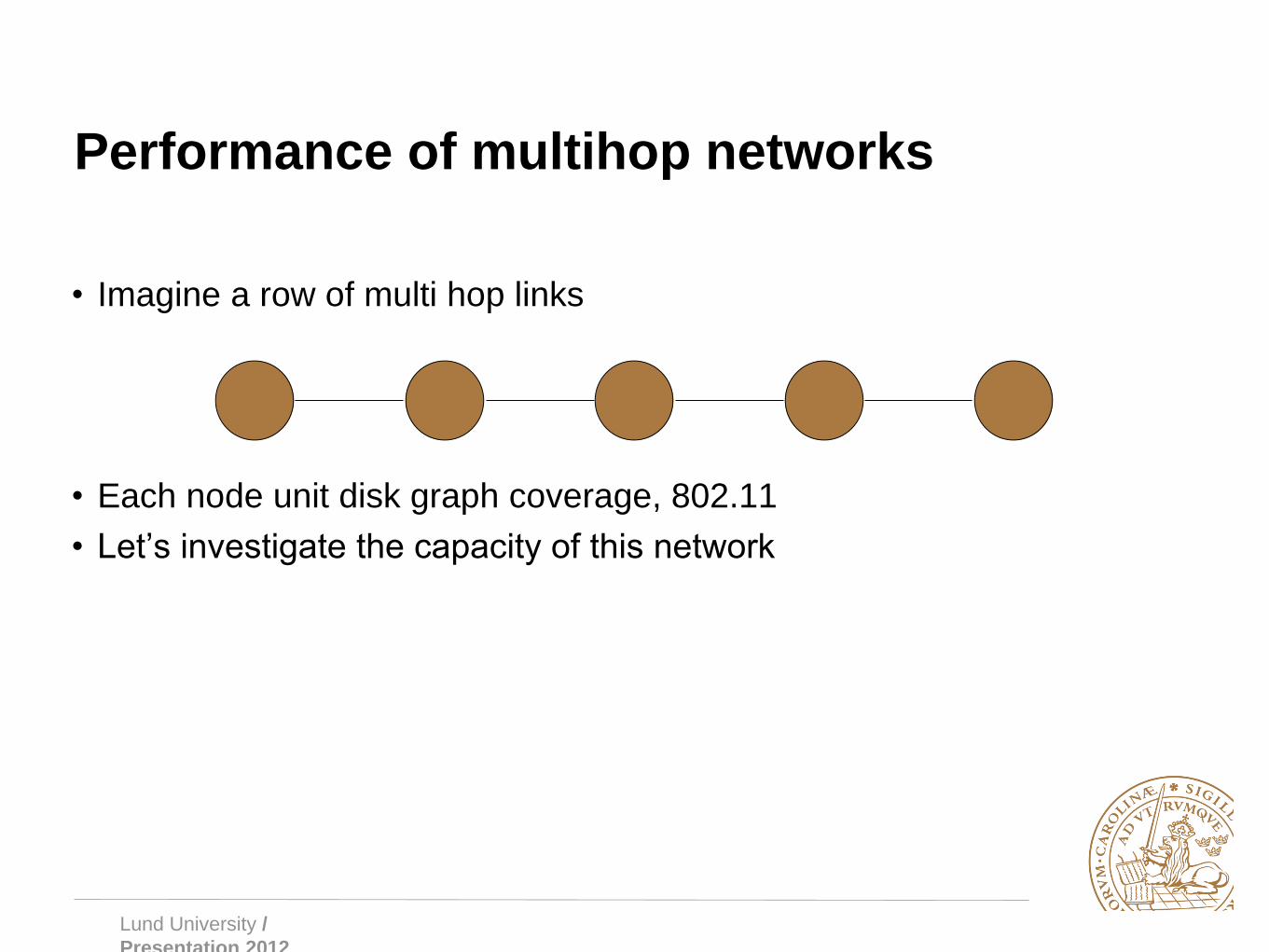
Performance of multihop networks
• Imagine a row of multi hop links
• Each node unit disk graph coverage, 802.11
• Let’s investigate the capacity of this network

Lund University /
Presentation 2012
Performance of multi hop networks
• Forwarding nodes n = 1-2-3-4-5
• 1 transmits to 2 => 3 silent
• 2 transmits to 3 => 4 silent, 1 cannot receive
• 3 transmits to 4 => 1 and 5 silent
• If infinite n, upper bound on capacity = 1/5 (one Tx, 4 silent hops)
1 2 3 4 5 6

Lund University /
Presentation 2012
Performance of interfering networks
• See Gupta & Kumar Trans. Info Theory for theoretical bounds
• Place n nodes arbitrarily on a unit disk area. Each node capacity is W
bps. The upper bound on capacity for the network is:
• Valid for surface and sphere
• Optimally placed nodes yield:

Lund University /
Presentation 2012
Work around
• Multi channel schemes
• Assign different channels to different links
– Significant capacity increase possible
– Added cost (multiple interfaces) and complexity
• Typically use some graph colouring algorithm or similar
• However, channel assignment not an easy task, see for example Manitpornsut and Landfeldt MSWIM 2009
• The work showed that minimising DOI increases the Hidden node
problem, severely impacts on voice performance
Lund University /
Presentation 2012
More complex routing protocols
• Traditional routing protocols (RIP, OSPF etc.) use no. hops as metric
• Consider other relevant metrics
– interference
– energy usage
– etc.
• Very complex task to construct such protocols that employ multi
constraint optimisation
– conflicting goals
– varying utility functions
• In WSN research, energy optimisation king
• In MESH research capacity king

Lund University /
Presentation 2012
Geographic Routing
• Routing based on nodes' physical positions, rather than network
addresses or routing tables
• Messages are then routed towards a destination location

Lund University /
Presentation 2012
Geographic Routing - Motivation
• Route discovery is costly in terms of time and energy
• Routing tables quickly become out of date in highly mobile networks
• Addressing a message to a position may be more useful than to a
network address
• Sending an accident or traffic jam notification to upstream vehicles
in a VANET
• Sending a request to collect sensor data in a particular region in a
WSN
• Tracking something through a WSN (e.g. an animal)

Lund University /
Presentation 2012
Localisation
• In order to perform geographic routing, we need to know the
locations of nodes
• Can do this using in-built location sensors such as GPS, IMU
• Or we can localise relative to other nodes by measuring e.g. TDOA
of beacons and then using trilateration

Lund University /
Presentation 2012
Greedy Forwarding
• Forward to the node that gets us the closest to the destination
• Guaranteed to have no loops
• Can use different metrics, e.g. distance to target, distance along the
source-destination line, smallest angle to destination (compass
routing)
Lund University /
Presentation 2012
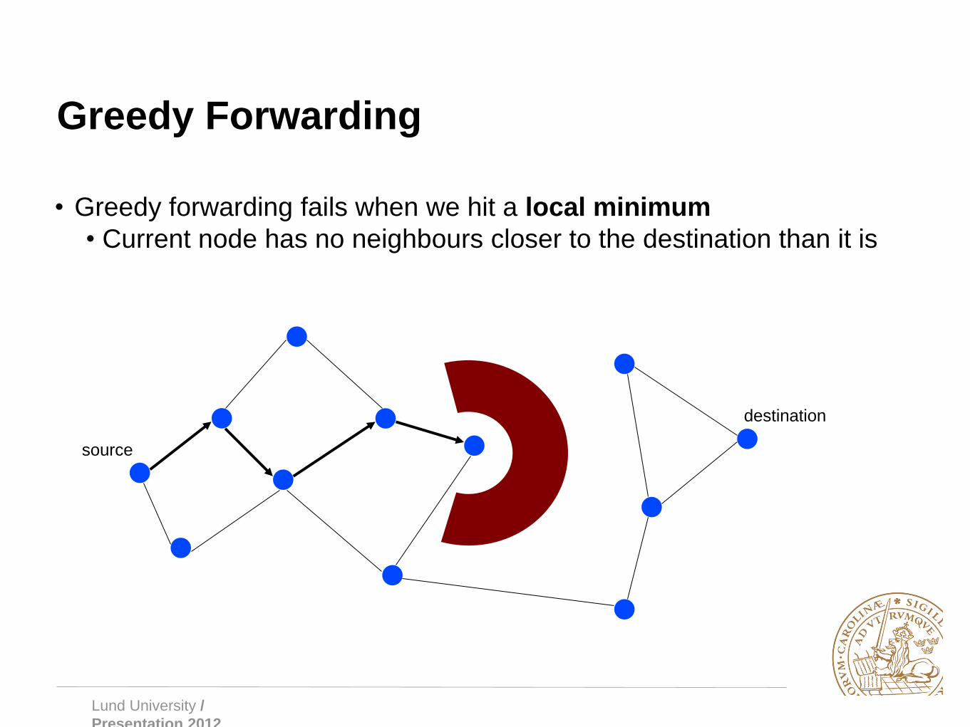
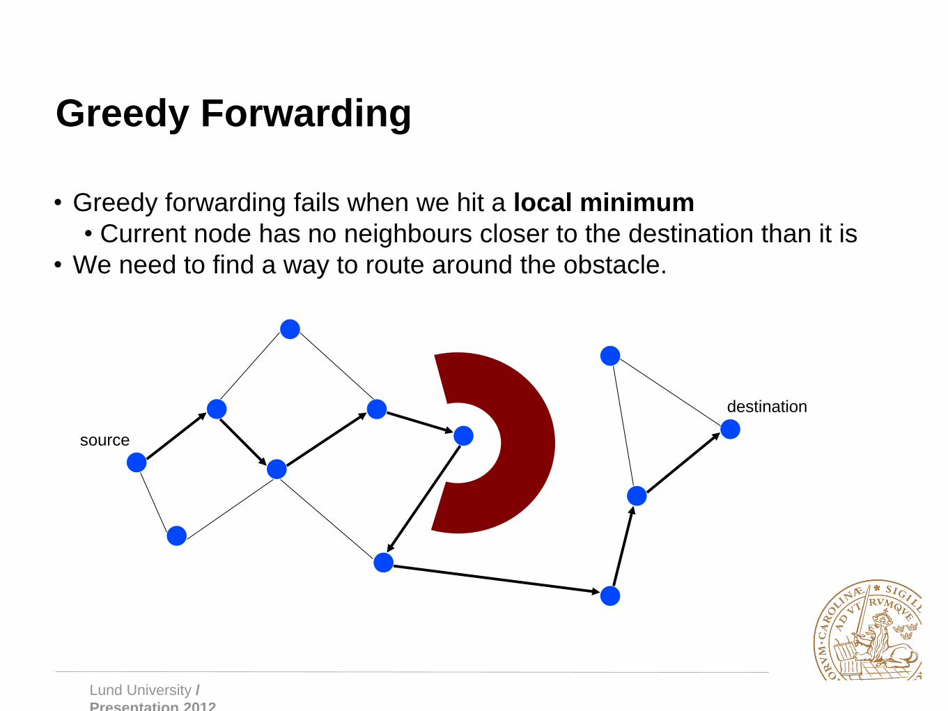
Greedy Forwarding
• Greedy forwarding fails when we hit a local minimum
• Current node has no neighbours closer to the destination than it is
source
destination
Lund University /
Presentation 2012
Greedy Forwarding
• Greedy forwarding fails when we hit a local minimum
• Current node has no neighbours closer to the destination than it is
• We need to find a way to route around the obstacle.
source
destination

Lund University /
Presentation 2012
Face Routing
• Route message along the face of a polygon in a set direction
• When continuing around the face of the polygon would cause you to
cross the line between the source and destination, change to the
next face

Lund University /
Presentation 2012
Face Routing
• Face routing requires that the graph is planar, i.e. no crossing links
• We can planarise the graph by removing crossing edges (e.g.
Delauney triangulation), but this can lead to increased hop count
• Less efficient, both in terms of delay and energy usage
• Face routing is also sensitive to localisation errors since it relies on
geometric information to choose forwarding nodes.
Lund University /
Presentation 2012
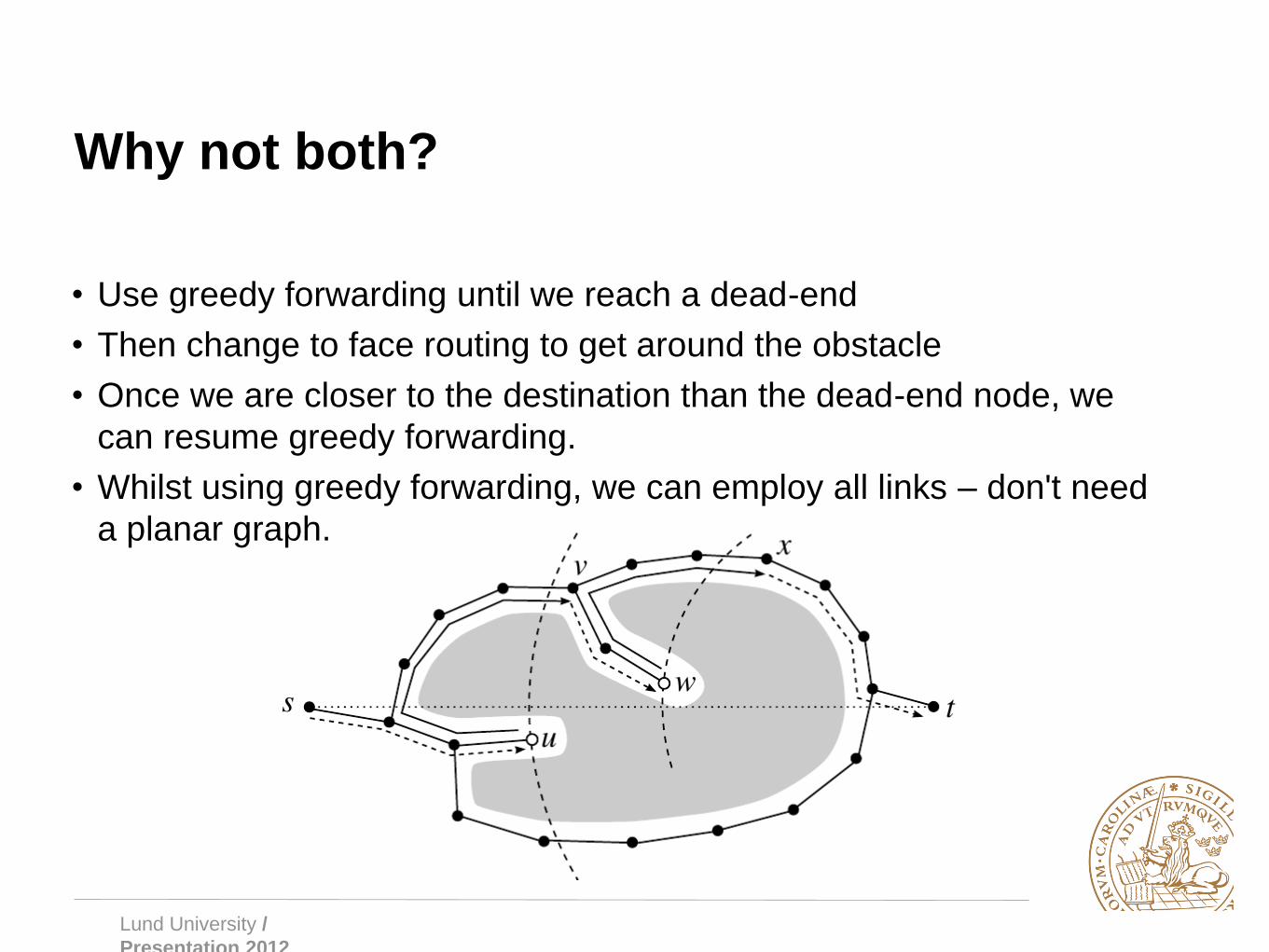
Why not both?
• Use greedy forwarding until we reach a dead-end
• Then change to face routing to get around the obstacle
• Once we are closer to the destination than the dead-end node, we
can resume greedy forwarding.
• Whilst using greedy forwarding, we can employ all links – don't need
a planar graph.
Lund University /
Presentation 2012
Contention-Based Greedy Forwarding
• When using greedy forwarding, we want to select the forwarding
node to be the one closest to the destination
• One way is to keep track of neighbours' locations but this increases
overhead and breaks down when we have high mobility.
• Instead, the source node sends RTS and potential forwarding nodes
respond with CTS at a time determined by their distance to the
destination
• Nodes that are closer to the destination will have a shorter timer
• Using this method can increase delay (must wait for the timers to
expire).
• We still need to know neighbours' locations to do face routing when
recovering from a dead end.
• Can request locations from neighbours when required

Lund University /
Presentation 2012
Contention-Based Greedy Forwarding

Lund University /
Presentation 2012
Realistic Network Models
• The unit disk is not a good model of radio
transmission
• Transmission radius is not uniform
• Three regions: good signal, degrading
signal, no signal
• In the intermediate region, we have a link,
but it is unreliable
• We can use the lognormal
shadowing or log-distance
path loss model to give a
reception probability for a
given distance.

Lund University /
Presentation 2012
Realistic Network Models
• Using greedy forwarding, we will select a forwarding node that is far
from previous node
• Likely to land in the region with poor signal
• This can lead to increased retransmissions
• We need to modify our greedy metric to take into account the cost of
retransmissions, and balance this against increased hop count as
results if we choose a closer node.

Lund University /
Presentation 2012
Realistic Network Models
• Nodes can record the number of successfully received packets S and
the total number of transmitted packets T on a give link.
• Packet reception rate (PRR):
• The PRR can serve as a reception probability for future
transmissions.
• We can then combine this with the distance gained to select a
forwarding node
• e.g. use PRR x distance as forwarding node selection metric,
instead of only distance

Wireless Network Constructs
Wireless networks
Infrastructure networks
Licensed spectrum (e.g. cellular)
Unlicensed spectrum (e.g.
Wifi)
Mesh
Ad-hoc networks
WiMAX (802.11s)
Centralised
802.11 a/b/g/n/ac in infrastructure
mode
Wireless sensor
networks
Mobile ad-hoc
networks
Vehicular ad-hoc
networks
Delay tolerant
networks GSM
UMTS
LTE
Personal Area
Networks
802.11 a/b/g/n/ac in ad-hoc
mode
Bluetooth
ZigBee (802.15.4)
WAVE (802.11p)
Short range
NFC RFID
Lund University /
Presentation 2012
The future of wireless networks
Lund University /
Presentation 2012
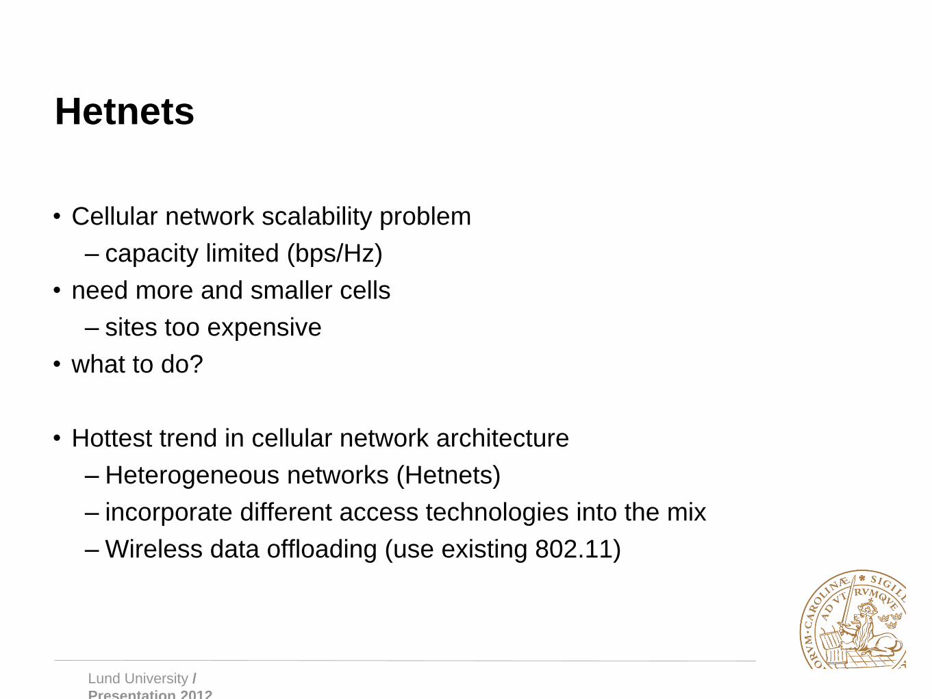
Hetnets
• Cellular network scalability problem
– capacity limited (bps/Hz)
• need more and smaller cells
– sites too expensive
• what to do?
• Hottest trend in cellular network architecture
– Heterogeneous networks (Hetnets)
– incorporate different access technologies into the mix
– Wireless data offloading (use existing 802.11)

Lund University /
Presentation 2012
Hetnets
Cellular
WiFi
Femto

Lund University /
Presentation 2012
The Internet of Things (IoT)
• Physical objects embedded with sesnors, actuators
processing power, and network connectivity
• ”Smart objects” collect and exchange data with each
other
• Machine-to-machine communication (M2M)
• Uses a range of different, interacting technologies
• WSNs, MANETs, VANETs, WiFi, Bluetooth,
ZigBee, RFID, …
• Applications in healthcare, energy management,
transportation, building automation, industrial
processes, …everything!


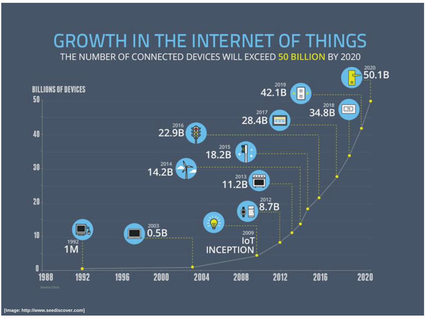
[Image: http://www.seediscover.com]

Lund University /
Presentation 2012
Self Organising Networks (SON)
• Increasing density of nodes
– management very hard
– cell and access network planning inherently difficult
– Customers not capable of configuring equipment
– some technologies operate in unlicensed spectrum
• Network needs to be self-organising
• Access configuration can be dynamically configured
– Channel assignment
– Power management
– Traffic separation
– etc.