ETSI GS NFV-TST 002 V1.1 · ETSI GS NFV-TST 002 ... the development of interoperability test...
47
ETSI GS NFV-TST 002 V1.1.1 (2016-10) Network Functions Virtualisation (NFV); Testing Methodology; Report on NFV Interoperability Testing Methodology Disclaimer The present document has been produced and approved by the Network Functions Virtualisation (NFV) ETSI Industry Specification Group (ISG) and represents the views of those members who participated in this ISG. It does not necessarily represent the views of the entire ETSI membership. GROUP SPECIFICATION
Transcript of ETSI GS NFV-TST 002 V1.1 · ETSI GS NFV-TST 002 ... the development of interoperability test...

ETSI GS NFV-TST 002 V1.1.1 (2016-10)
Network Functions Virtualisation (NFV); Testing Methodology;
Report on NFV Interoperability Testing Methodology
Disclaimer
The present document has been produced and approved by the Network Functions Virtualisation (NFV) ETSI Industry Specification Group (ISG) and represents the views of those members who participated in this ISG.
It does not necessarily represent the views of the entire ETSI membership.
GROUP SPECIFICATION

ETSI
ETSI GS NFV-TST 002 V1.1.1 (2016-10)2
Reference DGS/NFV-TST002
Keywords interoperability, NFV, testing, methodology
ETSI
650 Route des Lucioles F-06921 Sophia Antipolis Cedex - FRANCE
Tel.: +33 4 92 94 42 00 Fax: +33 4 93 65 47 16
Siret N° 348 623 562 00017 - NAF 742 C
Association à but non lucratif enregistrée à la Sous-Préfecture de Grasse (06) N° 7803/88
Important notice
The present document can be downloaded from: http://www.etsi.org/standards-search
The present document may be made available in electronic versions and/or in print. The content of any electronic and/or print versions of the present document shall not be modified without the prior written authorization of ETSI. In case of any
existing or perceived difference in contents between such versions and/or in print, the only prevailing document is the print of the Portable Document Format (PDF) version kept on a specific network drive within ETSI Secretariat.
Users of the present document should be aware that the document may be subject to revision or change of status. Information on the current status of this and other ETSI documents is available at
https://portal.etsi.org/TB/ETSIDeliverableStatus.aspx
If you find errors in the present document, please send your comment to one of the following services: https://portal.etsi.org/People/CommiteeSupportStaff.aspx
Copyright Notification
No part may be reproduced or utilized in any form or by any means, electronic or mechanical, including photocopying and microfilm except as authorized by written permission of ETSI.
The content of the PDF version shall not be modified without the written authorization of ETSI. The copyright and the foregoing restriction extend to reproduction in all media.
© European Telecommunications Standards Institute 2016.
All rights reserved.
DECTTM, PLUGTESTSTM, UMTSTM and the ETSI logo are Trade Marks of ETSI registered for the benefit of its Members. 3GPPTM and LTE™ are Trade Marks of ETSI registered for the benefit of its Members and
of the 3GPP Organizational Partners. GSM® and the GSM logo are Trade Marks registered and owned by the GSM Association.

ETSI
ETSI GS NFV-TST 002 V1.1.1 (2016-10)3
Contents
Intellectual Property Rights ................................................................................................................................ 5
Foreword ............................................................................................................................................................. 5
Modal verbs terminology .................................................................................................................................... 5
Executive summary ............................................................................................................................................ 5
Introduction ........................................................................................................................................................ 5
1 Scope ........................................................................................................................................................ 6
2 References ................................................................................................................................................ 6
2.1 Normative references ......................................................................................................................................... 6
2.2 Informative references ........................................................................................................................................ 6
3 Definitions and abbreviations ................................................................................................................... 7
3.1 Definitions .......................................................................................................................................................... 7
3.2 Abbreviations ..................................................................................................................................................... 7
4 Interoperability Testing Methodology Guidelines for NFV ..................................................................... 8
4.1 Introduction ........................................................................................................................................................ 8
4.2 Basic concepts for interoperability testing ......................................................................................................... 9
4.2.1 Overview ...................................................................................................................................................... 9
4.2.2 System Under Test (SUT) ............................................................................................................................. 9
4.2.3 Function Under Test (FUT) ........................................................................................................................ 10
4.2.4 Test interfaces ............................................................................................................................................. 10
4.2.5 Test Environment ........................................................................................................................................ 10
4.2.6 Test Descriptions ........................................................................................................................................ 10
4.2.7 Test drivers ................................................................................................................................................. 11
4.3 Interoperability Test Specifications .................................................................................................................. 11
4.3.1 Overview .................................................................................................................................................... 11
4.3.2 Generic SUT Architecture .......................................................................................................................... 11
4.3.3 Interoperable Features Statement (IFS) ...................................................................................................... 12
4.3.4 SUT Configurations .................................................................................................................................... 13
4.3.5 Test Suite Structure ..................................................................................................................................... 13
4.3.6 Test Purposes .............................................................................................................................................. 14
4.3.7 Test Descriptions ........................................................................................................................................ 14
4.4 Interoperability Testing Process ....................................................................................................................... 17
5 NFV SUT Architecture .......................................................................................................................... 18
5.1 NFV Generic SUT Architecture ....................................................................................................................... 18
5.2 NFV SUT Configuration 1 ............................................................................................................................... 19
5.3 NFV SUT Configuration 2a ............................................................................................................................. 19
5.4 NFV SUT Configuration 2b ............................................................................................................................. 20
5.5 NFV SUT Configuration 3 ............................................................................................................................... 21
5.6 NFV SUT Configuration 4 ............................................................................................................................... 22
6 NFV Interoperability Features ................................................................................................................ 23
6.1 VNF Package Management .............................................................................................................................. 23
6.1.1 Description .................................................................................................................................................. 23
6.1.2 SUT Configuration ..................................................................................................................................... 23
6.1.3 Observed Interfaces .................................................................................................................................... 23
6.1.4 Test Interfaces ............................................................................................................................................. 24
6.2 Software Image Management ........................................................................................................................... 24
6.2.1 Description .................................................................................................................................................. 24
6.2.2 SUT Configuration ..................................................................................................................................... 24
6.2.3 Observed Interfaces .................................................................................................................................... 24
6.2.4 Test Interfaces ............................................................................................................................................. 25
6.3 VNF Lifecycle Management ............................................................................................................................ 25
6.3.1 Description .................................................................................................................................................. 25
6.3.2 SUT Configuration ..................................................................................................................................... 25

ETSI
ETSI GS NFV-TST 002 V1.1.1 (2016-10)4
6.3.3 Observed Interfaces .................................................................................................................................... 25
6.3.4 Test Interfaces ............................................................................................................................................. 28
6.4 VNF Configuration Management ..................................................................................................................... 31
6.4.1 Description .................................................................................................................................................. 31
6.4.2 SUT Configuration ..................................................................................................................................... 31
6.4.3 Observed Interfaces .................................................................................................................................... 31
6.4.4 Test Interfaces ............................................................................................................................................. 31
6.5 VNF Fault Management ................................................................................................................................... 33
6.5.1 Description .................................................................................................................................................. 33
6.5.2 SUT Configuration ..................................................................................................................................... 33
6.5.3 Observed Interfaces .................................................................................................................................... 33
6.5.4 Test Interfaces ............................................................................................................................................. 33
6.6 VNF Performance Management ....................................................................................................................... 34
6.6.1 Description .................................................................................................................................................. 34
6.6.2 SUT Configuration ..................................................................................................................................... 34
6.6.3 Observed Interfaces .................................................................................................................................... 34
6.6.4 Test Interfaces ............................................................................................................................................. 35
6.7 Network Service Lifecycle Management ......................................................................................................... 36
6.7.1 Description .................................................................................................................................................. 36
6.7.2 SUT Configuration ..................................................................................................................................... 37
6.7.3 Observed Interfaces .................................................................................................................................... 37
6.7.4 Test Interfaces ............................................................................................................................................. 37
6.8 Network Service Fault Management ................................................................................................................ 39
6.8.1 Description .................................................................................................................................................. 39
6.8.2 SUT Configuration ..................................................................................................................................... 39
6.8.3 Observed Interfaces .................................................................................................................................... 39
6.8.4 Test Interfaces ............................................................................................................................................. 39
6.9 Network Service Performance Management .................................................................................................... 40
6.9.1 Description .................................................................................................................................................. 40
6.9.2 SUT Configuration ..................................................................................................................................... 40
6.9.3 Observed Interfaces .................................................................................................................................... 40
6.9.4 Test Interfaces ............................................................................................................................................. 41
Annex A (informative): NFV IFS Pro-forma example ........................................................................ 43
Annex B (informative): Authors & contributors ................................................................................. 45
Annex C (informative): Bibliography ................................................................................................... 46
History .............................................................................................................................................................. 47
ETSI
ETSI GS NFV-TST 002 V1.1.1 (2016-10)5
Intellectual Property Rights IPRs essential or potentially essential to the present document may have been declared to ETSI. The information pertaining to these essential IPRs, if any, is publicly available for ETSI members and non-members, and can be found in ETSI SR 000 314: "Intellectual Property Rights (IPRs); Essential, or potentially Essential, IPRs notified to ETSI in respect of ETSI standards", which is available from the ETSI Secretariat. Latest updates are available on the ETSI Web server (https://ipr.etsi.org/).
Pursuant to the ETSI IPR Policy, no investigation, including IPR searches, has been carried out by ETSI. No guarantee can be given as to the existence of other IPRs not referenced in ETSI SR 000 314 (or the updates on the ETSI Web server) which are, or may be, or may become, essential to the present document.
Foreword This Group Specification (GS) has been produced by ETSI Industry Specification Group (ISG) Network Functions Virtualisation (NFV).
Modal verbs terminology In the present document "shall", "shall not", "should", "should not", "may", "need not", "will", "will not", "can" and "cannot" are to be interpreted as described in clause 3.2 of the ETSI Drafting Rules (Verbal forms for the expression of provisions).
"must" and "must not" are NOT allowed in ETSI deliverables except when used in direct citation.
Executive summary
The present document studies how interoperability test methodology can be applied to NFV by analysing some of the core NFV capabilities and the interactions between the functional blocks defined within the NFV architectural framework required to enable them.
Introduction
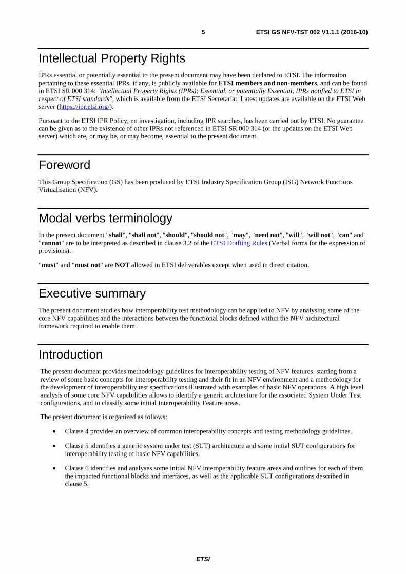
The present document provides methodology guidelines for interoperability testing of NFV features, starting from a review of some basic concepts for interoperability testing and their fit in an NFV environment and a methodology for the development of interoperability test specifications illustrated with examples of basic NFV operations. A high level analysis of some core NFV capabilities allows to identify a generic architecture for the associated System Under Test configurations, and to classify some initial Interoperability Feature areas.
The present document is organized as follows:
• Clause 4 provides an overview of common interoperability concepts and testing methodology guidelines.
• Clause 5 identifies a generic system under test (SUT) architecture and some initial SUT configurations for interoperability testing of basic NFV capabilities.
• Clause 6 identifies and analyses some initial NFV interoperability feature areas and outlines for each of them the impacted functional blocks and interfaces, as well as the applicable SUT configurations described in clause 5.

ETSI
ETSI GS NFV-TST 002 V1.1.1 (2016-10)6
1 Scope The present document provides some guidelines for NFV interoperability testing and identifies a generic System Under Test (SUT) architecture for NFV, some initial SUT configurations, and some interoperability feature areas derived from core NFV capabilities.
2 References
2.1 Normative references References are either specific (identified by date of publication and/or edition number or version number) or non-specific. For specific references, only the cited version applies. For non-specific references, the latest version of the referenced document (including any amendments) applies.
Referenced documents which are not found to be publicly available in the expected location might be found at https://docbox.etsi.org/Reference.
NOTE: While any hyperlinks included in this clause were valid at the time of publication, ETSI cannot guarantee their long term validity.
The following referenced documents are necessary for the application of the present document.
Not applicable.
2.2 Informative references References are either specific (identified by date of publication and/or edition number or version number) or non-specific. For specific references, only the cited version applies. For non-specific references, the latest version of the referenced document (including any amendments) applies.
NOTE: While any hyperlinks included in this clause were valid at the time of publication, ETSI cannot guarantee their long term validity.
The following referenced documents are not necessary for the application of the present document but they assist the user with regard to a particular subject area.
[i.1] ISO/IEC 9646 (parts 1 to 7): "Information technology - Open Systems Interconnection - Conformance testing methodology and framework".
[i.2] ETSI EG 202 237: "Methods for Testing and Specification (MTS); Internet Protocol Testing (IPT); Generic approach to interoperability testing".
[i.3] ETSI EG 202 568: "Methods for Testing and Specification (MTS); Internet Protocol Testing (IPT); Testing: Methodology and Framework". .
[i.5] ETSI GS NFV 002: "Network Functions Virtualisation (NFV); Architectural Framework".
[i.6] ETSI GS NFV-MAN 001: "Network Functions Virtualisation (NFV); Management and Orchestration".
[i.7] ETSI GS NFV-IFA 010 (V2.1.1): "Network Functions Virtualisation (NFV); Management and Orchestration; Functional requirements specification".
[i.8] ETSI GS NFV-IFA 005 (V2.1.1): "Network Functions Virtualisation (NFV); Management and Orchestration; Or-Vi reference point - Interface and Information Model Specification".
[i.9] ETSI GS NFV-IFA 006: "Network Functions Virtualisation (NFV); Management and Orchestration; Vi-Vnfm reference point - Interface and Information Model Specification".

ETSI
ETSI GS NFV-TST 002 V1.1.1 (2016-10)7
[i.10] ETSI GS NFV-IFA 007: "Network Functions Virtualisation (NFV); Management and Orchestration; Or-Vnfm reference point - Interface and Information Model Specification".
[i.11] ETSI GS NFV-IFA 008: "Network Functions Virtualisation (NFV); Management and Orchestration; Ve-Vnfm reference point - Interface and Information Model Specification".
[i.12] ETSI GS NFV-IFA 013: "Network Functions Virtualisation (NFV); Management and Orchestration; Os-Ma-Nfvo reference point - Interface and Information Model Specification".
[i.13] ETSI GS NFV 003: "Network Functions Virtualisation (NFV); Terminology for main concepts in NFV".
3 Definitions and abbreviations
3.1 Definitions For the purposes of the present document, the terms and definitions given in ETSI GS NFV 003 [i.13] apply.
3.2 Abbreviations For the purposes of the present document, the terms and definitions given in ETSI GS NFV 003 [i.13] and the following apply:
API Application Programming Interface CON CONformance DUT Device Under Test FUT Function Under Test IFS Interoperable Features Statement IOP InterOPerability IUT Implementation Under Test LCM Life Cycle Management MMI Man-Machine Interface NSD Network Service Descriptor OSS Operation System Support PICS Protocol Implementation Conformance Statement QE Qualified Equipment QF Qualified Function SUT System Under Test TD Test Description TSS Test Suite Structure VNFFG Virtual Network Function Forwarding Graph

ETSI
ETSI GS NFV-TST 002 V1.1.1 (2016-10)8
4 Interoperability Testing Methodology Guidelines for NFV
4.1 Introduction Well established test methodology like ETSI EG 202 237 [i.2] and ETSI EG 202 568 [i.3] describe two main and complementary ways of testing devices implementing standardized services, which each have benefits and limitations:
• Conformance Testing can show that a product correctly implements a particular standard, that is, it establishes whether or not the Implementation Under Test (IUT) meets the requirements specified by the standard. For example, it will test protocol message contents and format as well as the permitted sequences of messages. In this context:
- There is only one Implementation Under Test, which is part of the System Under Test.
- Tests are performed at open standardized interfaces which might not be accessible to an end user, and executed by a dedicated test system that has full control of the System Under Test and the ability to observe all incoming and out coming communications.
- The high degree of control of the test system over the sequence and contents of the protocol messages allows to test both valid and invalid behaviour.
Figure 1: Conformance testing
• Interoperability Testing can demonstrate that a product will work with other like products: it proves that end-to-end functionality between (at least) two functions is as required by the standard(s) on which those functions are based. In this context:
- The System Under Test (SUT) is made of the combination of different Functions Under Test (FUT) coming from different suppliers.
- Interoperability tests are based on functionality as experienced by a user, where the user may be human or a software application.
- Tests are performed and observed at functional interfaces such as Man-Machine Interfaces (MMIs), protocol service interfaces and Application Programming Interfaces (APIs).
- Testing at functional interfaces implies that interoperability tests can only describe functional behaviour and sometimes it might not be possible to trigger or test protocol error behaviour on the interface(s) among the FUTs.
Figure 2: Interoperability testing
NOTE: The concept of Function Under Test used in the present document corresponds to the concept of Device Under Test (DUT) introduced in ETSI EG 202 568 [i.3].

ETSI
ETSI GS NFV-TST 002 V1.1.1 (2016-10)9
Conformance testing in conjunction with interoperability testing provides both the proof of conformance and the guarantee of interoperation. ETSI EG 202 237 [i.2] and ETSI EG 202 568 [i.3] describe several approaches on how to combine the two methods, the most common one being Interoperability Testing with Conformance Checks, where reference points between the FUTs are monitored to verify the appropriate sequence and contents of protocol messages, API calls, interface operations, etc.
Clauses 4.2 to 4.4 provide an overview of the main concepts and practices associated with interoperability testing. The intention is to develop simple and pragmatic guidelines that can be used as a "cook-book", rather than a rigid prescription of how to perform NFV interoperability testing.
The main areas of these guidelines are as follows:
• Definition of basic concepts.
• Instructions for the development of interoperability test specifications, including:
- Definition of a generic System Under Test (SUT) architecture.
- Identification of interoperability features.
- Specification of SUT configurations and Test Descriptions.
• Description of the interoperability testing process.
As their name implies, guidelines are only for guidance and the actual process followed should use and adapt whichever of these guidelines are most applicable in each particular situation. In some cases this may mean the application of all aspects.
4.2 Basic concepts for interoperability testing
4.2.1 Overview
There are a number of different terms and concepts that can be used when describing a test methodology. Clauses 4.2 to 4.4 describe the most important concepts used by these guidelines, which can been categorized either as part of the System Under Test (SUT) or as part of the Test Environment.
Figure 3 provides an overview of these basic concepts, which are described in detail in clauses 4.2.2 to 4.2.7.
Figure 3: Illustration of basic concepts
4.2.2 System Under Test (SUT)
In the context of interoperability testing, the System Under Test (SUT) is made of a number of interacting Functions Under Test (FUTs) coming from different suppliers.

ETSI
ETSI GS NFV-TST 002 V1.1.1 (2016-10)10
Depending on the complexity of the end-to-end system, the overall number of FUTs comprising the SUT, and the interactions among them, it might be advisable to define different SUT configuration addressing specific functional areas or groups of tests.
The first steps towards defining an Interoperability Tests Specification are identifying the Functions Under Test and describing a generic architecture where all the required SUT configurations will fit.
4.2.3 Function Under Test (FUT)
In the context of NFV, a Function Under Test is a combination of software and/or hardware items which implement the functionality of one or several NFV functional blocks and interact with other FUTs via one or more reference points, as described in ETSI GS NFV 002 [i.5].
NOTE: When using Interoperability Test Specifications in a certification scheme, the notion of Qualified Equipment (QE) or Qualified Function (QF) applies. A QF is a FUT that has successfully been tested with other QFs. The usage of interoperability Test Specifications in a certification scheme is out of the scope of the present document. Further details on this topic can be found at ETSI EG 202 237 [i.2].
4.2.4 Test interfaces
The interfaces that are made available by the SUT to enable the testing are usually known as the test interfaces. These interfaces are accessed by the test drivers to trigger and verify the test behaviour, as described in clause 4.2.7. Other (non-test) interfaces offered by the SUT can be used for monitoring, log analysis, etc.
In the simplest case, the test interfaces will be the normal user interfaces offered by some of the FUTs (command line, GUI, web interface, etc.). FUTs may also offer APIs over which interoperability testing can be performed either manually using a dedicated application, or automatically using a programmable test function.
In some cases, observing and verifying the functional behaviour or responses of one FUT may require analysing its logs or records. In that case, it is recommended to pre-define those log messages or records to avoid ambiguity in their interpretation.
Additionally, while in the context of interoperability testing interfaces between the FUTs are not considered to be test interfaces, combining interoperability testing with conformance checks may require to monitor those interfaces to assess the conformance of the exchanged information or messages.
4.2.5 Test Environment
Interoperability testing involves control and observation at the functional (rather than protocol) level. The Test Environment is the combination of equipment, functions and procedures which allow testing the interoperability of the FUTs. Entities in the test environment access the different Functions Under Test via the Test Interfaces offered by the SUT. These entities ensure the selection, interpretation and execution of the test descriptions, coordination and synchronization of the actions on the test interfaces, and provide mechanisms for logging, reporting, monitoring and observing the interactions among the FUTs, etc.
4.2.6 Test Descriptions
A test description provides the detailed set of instructions (or steps) that need to be followed in order to perform a test. Most often, interoperability tests are described in terms of actions that can be performed by the user(s) of the endpoint device(s).
In the case where the test is executed by a human operator, test will be described in natural language. In the case where the tests are automated, a programming or test language will be used to implement the test descriptions.
The steps in the test description can be of different nature, depending on the kind of action required: trigger a behaviour on one FUT, verify the functional response on another FUT, configure the SUT (add/remove a FUT), check a log, etc. Each step identifies the FUT and/or the interface targeted by the action.

ETSI
ETSI GS NFV-TST 002 V1.1.1 (2016-10)11
4.2.7 Test drivers
The test driver realizes the steps specified in a test description at one specific test interface. Testing efficiency and consistency can be improved by implementing the role of the test driver via an automatic device programmed to carry out the specified test steps. This approach may require standardized test interfaces in the FUTs, or at least well-documented, open interfaces providing the needed functionality.
In any given instance of testing, there may be more than one test interface over which the tests will be executed. In that case, coordination among the different test drivers and synchronization of the actions performed by them will be required. This test coordination role can be played by one of the test drivers, or by and additional entity in the test environment.
4.3 Interoperability Test Specifications
4.3.1 Overview
The main steps involved in the process of developing an interoperability test specification are as follows:
• describing a generic architecture for the System Under Test;
• collecting interoperable (IOP) features and requirements in the Interoperable Features Statement (IFS);
• identifying the SUT Configurations;
• defining a structure for the Test Specification (TSS);
• writing Test Descriptions (TDs) for each item in the IFS.
Figure 4: Interoperability Test Specification Development process
4.3.2 Generic SUT Architecture
A generic SUT architecture provides an abstract framework within which any specific SUT configuration can fit in. The starting point for defining a generic SUT architecture is most often the functional architecture described in the base standards, in combination with pragmatic input on how the industry and open source projects are actually implementing these functional blocks (grouping, bundling, etc.).
In a complex system, it may be required to define several SUT configurations to cover all the specified groups of tests. Defining the generic architecture and identifying the SUT configurations at an early stage helps to provide a structure for the test descriptions later. The generic test architecture is usually specified as a diagram and identifies:
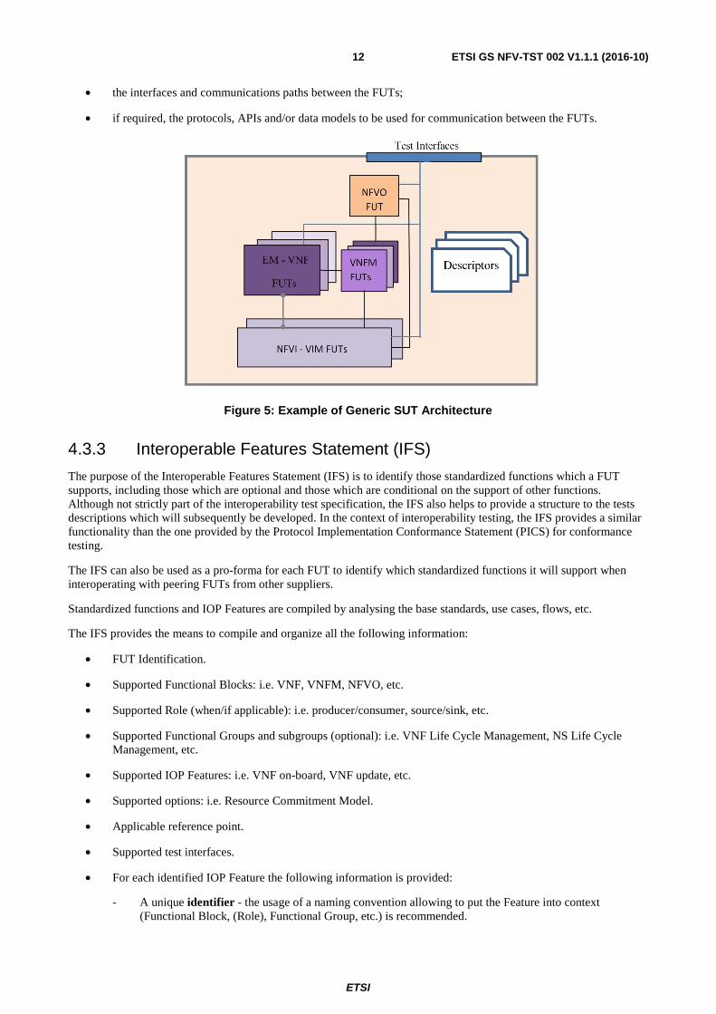
• the Functions Under Test, and the functional blocks implemented by them;
ETSI
ETSI GS NFV-TST 002 V1.1.1 (2016-10)12
• the interfaces and communications paths between the FUTs;
• if required, the protocols, APIs and/or data models to be used for communication between the FUTs.
Figure 5: Example of Generic SUT Architecture
4.3.3 Interoperable Features Statement (IFS)
The purpose of the Interoperable Features Statement (IFS) is to identify those standardized functions which a FUT supports, including those which are optional and those which are conditional on the support of other functions. Although not strictly part of the interoperability test specification, the IFS also helps to provide a structure to the tests descriptions which will subsequently be developed. In the context of interoperability testing, the IFS provides a similar functionality than the one provided by the Protocol Implementation Conformance Statement (PICS) for conformance testing.
The IFS can also be used as a pro-forma for each FUT to identify which standardized functions it will support when interoperating with peering FUTs from other suppliers.
Standardized functions and IOP Features are compiled by analysing the base standards, use cases, flows, etc.
The IFS provides the means to compile and organize all the following information:
• FUT Identification.
• Supported Functional Blocks: i.e. VNF, VNFM, NFVO, etc.
• Supported Role (when/if applicable): i.e. producer/consumer, source/sink, etc.
• Supported Functional Groups and subgroups (optional): i.e. VNF Life Cycle Management, NS Life Cycle Management, etc.
• Supported IOP Features: i.e. VNF on-board, VNF update, etc.
• Supported options: i.e. Resource Commitment Model.
• Applicable reference point.
• Supported test interfaces.
• For each identified IOP Feature the following information is provided:
- A unique identifier - the usage of a naming convention allowing to put the Feature into context (Functional Block, (Role), Functional Group, etc.) is recommended.

ETSI
ETSI GS NFV-TST 002 V1.1.1 (2016-10)13
- A short description of the feature.
- A reference to the base specification.
- The feature status: Mandatory (M), Optional (O), Conditional (C).
- In the IFS pro-forma, an additional field allows to state whether the implementation in question supports or not the feature (Y/N).
The IFS can be compiled in different formats, such as a collection of related tables or a database.
Before having completed the development of the Test Specification, the IFS can only be considered a stable draft. As the test specification matures, it is possible that errors and omissions in the IFS will be identified. Once the test specification is complete, has been validated, and all the detected errors have been fixed, the IFS can also be considered complete. An example of an NFV IFS pro-forma is provided in annex A.
4.3.4 SUT Configurations
The Test Specification clearly identifies and eventually provides a diagram for each valid configuration derived from the generic SUT architecture. A valid configuration is a specific subset of the generic SUT architecture to which a given group of test descriptions applies. Identifying and describing valid SUT configurations at an early stage in the Test Specification development process helps to:
• Structure the test specifications in groups.
• Understand the applicability and scope of each test group.
The SUT configurations clearly identifies:
• the required Functions Under Test;
• the observed interfaces exposed/consumed by the FUTs;
• the test interfaces.
Figure 6: SUT configuration example
4.3.5 Test Suite Structure
The Test Suite Structure is the equivalent of the Table of Contents of the Test Descriptions. The goal of this step is to facilitate:
• Grouping the TDs together in a logical way.
FUT 1
Descriptor
Test Interfaces
FUT 2
Observed Interface 1
Test Interface 1 11Interface 1
Test Interface 2 Interface 2

ETSI
ETSI GS NFV-TST 002 V1.1.1 (2016-10)14
• Addressing all the targeted IOP features described in the standard(s).
• Providing a minimum coverage of each group.
There is no hard and fast rule that can be used to determine how a test specification is divided up into test groups. In many cases, the division will be rather arbitrary and based on the preferences of the author(s). However, the following categorizations can be considered when identifying appropriate test groups within the Test Suite Structure (TSS):
• SUT configuration: A test group for each valid configuration specified.
• Functionality: A test group for each of the major functions supported. For example:
- VNF on-boarding;
- VNF LCM;
- NS LCM;
- etc.
• Success or failure: A test group for normal behaviour and another for exceptional behaviour.
4.3.6 Test Purposes
As recommended in ISO/IEC 9646 [i.1], before writing the individual steps that are required to complete a test description (how), a full description of the objective of each test case (what) is provided.
These Test Purposes (TPs) are based on the IOP features identified in the relevant standard(s), and compiled in the Interoperable Feature Statement (IFS).
EXAMPLE: Test Purpose: To verify that a VNF Package can be on-boarded.
In practice, the Test Purposes can be part of the Test Descriptions, as described in clause 4.3.7.
4.3.7 Test Descriptions
For each Test Purpose, one or several Test Descriptions can be specified. Test Descriptions compile all the information required to execute a test. They describe all the steps required to achieve a test purpose (how). The following information is provided with each Test Description:
• Identifier: A unique identifier is assigned to each Test Description. The usage of a well-defined naming convention allowing to put the TD into context (Functional Group, Feature, etc.) is recommended.
• Test Purpose: Description of the objective of the TD (what), see clause 4.3.6.
• Configuration: Reference to the applicable SUT configuration(s), see clause 4.3.4.
• References: Reference to the base specification(s) which describe the feature being tested.
• Applicability: List of items in the IFS that need to be supported by the DUTs in the SUT in order to be able to execute the test, see 4.3.3. If the list contains an optional item, then the test is optional.
• Pre-test conditions: (Optional) Specific conditions that need to be met by the SUT prior to start executing the test sequence. It can include information about configuration, and/or initial state of the SUT.
• Test Sequence: Detailed description of the steps that are to be followed in order to achieve the stated test purpose. These steps are specified in a clear and unambiguous way but without placing unreasonable restrictions on how the step is performed. Clarity and precision are important to ensure that the step can followed exactly. The lack of restrictions is necessary to ensure that the test can apply to a range of different types of implementation.

ETSI
ETSI GS NFV-TST 002 V1.1.1 (2016-10)15
Table 1: Test Description Template Example
Interoperability Test Description Identifier Unique test description ID: TD_AB_XXX_00. Follows a well-defined naming
convention Test Purpose a concise summary of the test reflecting its purpose and allowing readers to easily
distinguish this test from any other test in the document Configuration List of all the FUTs required devices for running this test, possibly also including a
(reference to) an illustration of the SUT configuration References List of references to the base specification clause(s), use case(s), requirement(s),
etc. which are either used in the test or define the functionality being tested Applicability List of features and capabilities in the IFS which are required to be supported by the
SUT in order to execute this test (e.g. if this list contains an optional feature to be supported, then the test is optional).
Pre-test conditions List of test specific pre-conditions that need to be met by the SUT including
information about configuration, i.e. precise description of the initial state of the SUT prior to start executing the test sequence • •
Test Sequence Step Type Description Result
1 <Type> Step description 2 3 4 5 6 IOP Verdict
The Steps in the Test Sequence can be of different type, depending on their purpose:
• A stimulus corresponds to an event that triggers a specific action on a FUT, like sending a message for instance.
• A configure corresponds to an action to modify the FUT or SUT configuration.
• An IOP check consists of observing that one FUT behaves as described in the standard: i.e. resource creation, update, deletion, etc. For each IOP check in the Test Sequence, a result can be recorded.
• The overall IOP Verdict will be considered OK if all the IOP checks in the sequence are OK.
See here after an example of how an Interoperability Test Description could be specified for the On-board VNF Package flow described in ETSI GS NFV-MAN 001 [i.6], clause B.2.1.

ETSI
ETSI GS NFV-TST 002 V1.1.1 (2016-10)16
Figure 7: On-board VNF Package flow
Table 2: Test Description Example for VNF On-boarding (IOP only)
Interoperability Test Description Identifier TD_VNFLCM_OB_SUCCESS_1 Test Purpose To verify that a VNF Package can be on-boarded Configuration CFG_VNFLCM_OB
NFVO, VIM References ETSI GS NFV-MAN 001 [i.6] clause B.2.1 Applicability VIM_VNFLCM_OB1
NFVO_VNFLCM_OB1 Pre-test conditions • VNFD format is valid
• VNFD contains all the mandatory elements • […]
Test Sequence Step Type Description Result
1 stimulus Trigger VNF Package on boarding on NFVO 2 IOP check Catalogue is updated with VNF Package 3 IOP check Software Image is added to the VIM's image repository IOP Verdict
In the context of Interoperability Testing with Conformance Checks, an additional step type, CON checks can be used to verify the appropriate sequence and contents of protocol messages, API calls, interface operations, etc.
ETSI
ETSI GS NFV-TST 002 V1.1.1 (2016-10)17
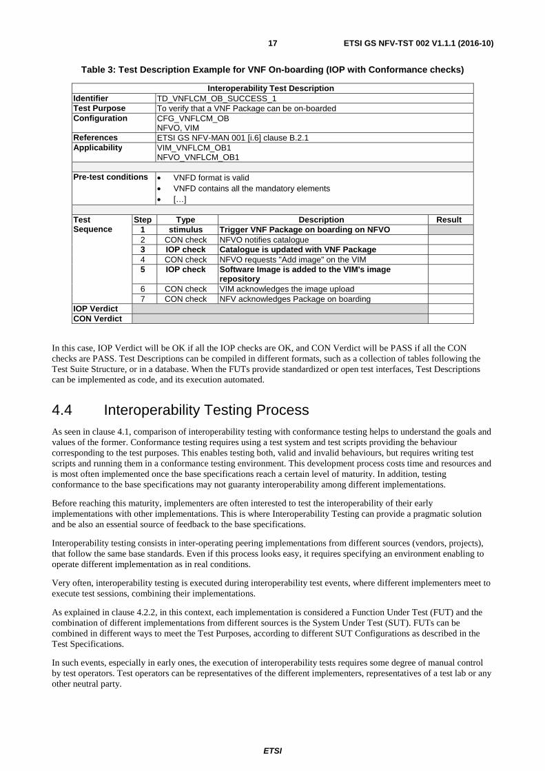
Table 3: Test Description Example for VNF On-boarding (IOP with Conformance checks)
Interoperability Test Description Identifier TD_VNFLCM_OB_SUCCESS_1 Test Purpose To verify that a VNF Package can be on-boarded Configuration CFG_VNFLCM_OB
NFVO, VIM References ETSI GS NFV-MAN 001 [i.6] clause B.2.1 Applicability VIM_VNFLCM_OB1
NFVO_VNFLCM_OB1 Pre-test conditions • VNFD format is valid
• VNFD contains all the mandatory elements • […]
Test Sequence
Step Type Description Result 1 stimulus Trigger VNF Package on boarding on NFVO 2 CON check NFVO notifies catalogue 3 IOP check Catalogue is updated with VNF Package 4 CON check NFVO requests "Add image" on the VIM 5 IOP check Software Image is added to the VIM's image
repository
6 CON check VIM acknowledges the image upload 7 CON check NFV acknowledges Package on boarding
IOP Verdict CON Verdict
In this case, IOP Verdict will be OK if all the IOP checks are OK, and CON Verdict will be PASS if all the CON checks are PASS. Test Descriptions can be compiled in different formats, such as a collection of tables following the Test Suite Structure, or in a database. When the FUTs provide standardized or open test interfaces, Test Descriptions can be implemented as code, and its execution automated.
4.4 Interoperability Testing Process As seen in clause 4.1, comparison of interoperability testing with conformance testing helps to understand the goals and values of the former. Conformance testing requires using a test system and test scripts providing the behaviour corresponding to the test purposes. This enables testing both, valid and invalid behaviours, but requires writing test scripts and running them in a conformance testing environment. This development process costs time and resources and is most often implemented once the base specifications reach a certain level of maturity. In addition, testing conformance to the base specifications may not guaranty interoperability among different implementations.
Before reaching this maturity, implementers are often interested to test the interoperability of their early implementations with other implementations. This is where Interoperability Testing can provide a pragmatic solution and be also an essential source of feedback to the base specifications.
Interoperability testing consists in inter-operating peering implementations from different sources (vendors, projects), that follow the same base standards. Even if this process looks easy, it requires specifying an environment enabling to operate different implementation as in real conditions.
Very often, interoperability testing is executed during interoperability test events, where different implementers meet to execute test sessions, combining their implementations.
As explained in clause 4.2.2, in this context, each implementation is considered a Function Under Test (FUT) and the combination of different implementations from different sources is the System Under Test (SUT). FUTs can be combined in different ways to meet the Test Purposes, according to different SUT Configurations as described in the Test Specifications.
In such events, especially in early ones, the execution of interoperability tests requires some degree of manual control by test operators. Test operators can be representatives of the different implementers, representatives of a test lab or any other neutral party.
ETSI
ETSI GS NFV-TST 002 V1.1.1 (2016-10)18
During a Test Session, for each Interoperability Test Description in the Test Specification the following actions are taken as part of the test execution:
1) Determine if the Test Description (TD) is in scope, that is, if all the IFS listed in the Applicability field are met by all the concerned FUTs.
2) Setup the System Under Test (i.e. combination of FUTs) according to the Configuration described in the TD.
3) Configure each FUT to match the configuration of peering FUTs and to ensure the resulting System Under Test (SUT) will follow the expected test behaviour and meet the Test Purpose.
4) Take the System Under Test to the state described in the pre-test conditions.
5) Follow the steps Test Sequence, which will be a combination of the following:
- Trigger an action on one of the FUTs to initiate the expected test process described in the Stimulus steps.
- Verify that the FUTs behave according to the expectations, that is, as described in the IOP Check steps. Record the result.
- Optionally, when running Interoperability Testing with Conformance Checks, check for the compliance of the interaction among the concerned FUTs, as described in the CON Check steps. Record the result.
6) Assess the Test Verdict as follows:
- IOP Verdict, will be OK if all the IOP Checks are OK.
- When running Interoperability Testing with Conformance Checks, CON Verdict will be PASS if all the CON Checks are PASS.
As previously mentioned, conformance and interoperability are complementary and these two verdicts are independent: there exist interoperable implementations that fail the conformance checks, and there might be perfectly conformant implementations that do not interoperate. The latest is most often caused by an ambiguity or gap in the base specification. Interoperability testing contributes to detect and fix such issues, and increase the technical quality of the base specification.
Experience shows that a good Test Suite Structure (TSS) helps to maximize of the number of Test Descriptions that can be run during a Test Session. This requires grouping together the Test Descriptions that apply to a same SUT Configuration and, when possible, do not require reconfiguration of the FUTs. The order of the Test Descriptions can also play a significant role in the efficiency of the Test Sessions.
5 NFV SUT Architecture
5.1 NFV Generic SUT Architecture The generic NFV System Under Test (SUT) architecture depicted below summarizes the NFV Functions Under Test, Descriptors, Observed Interfaces and Test Interfaces required to test the NFV Interoperability Features captured in clause 6. This generic NFV SUT architecture is decomposed in the clauses 5.2 to 5.6 in a number of NFV SUT Configurations, each of them addressing specific Interoperability Features derived from basic NFV capabilities.

ETSI
ETSI GS NFV-TST 002 V1.1.1 (2016-10)19
Figure 8: NFV SUT Architecture
5.2 NFV SUT Configuration 1 NFV System Under Test Configuration 1 allows testing NFV capabilities related to the management of Network Service Descriptors, VNF Descriptors and VNF Packages.
The main functional blocks impacted by these capabilities are the NFVO, the VNFM and the VIM, and the observed reference points are the Or-vnfm, Vi-vnfm and Or-vi.
Figure 9: NFV SUT Configuration 1
5.3 NFV SUT Configuration 2a NFV System Under Test Configuration 2a allows testing NFV capabilities related to VNF Lifecycle, Fault and Performance Management, as well as VNF-related Resources Management in Direct Mode.
VNFM FUT
NFVO FUT
VNFD
Test Interfaces
VIM FUT
VNF Package
NSD
NFVO:Or-vnfm
VIM:Vi-vnfm
VIM:Or-vi
Sw Image
NFVI FUT
NFVO: Nfvo-tst
VNFM:vnfm-tst
VIM: vim-tst

ETSI
ETSI GS NFV-TST 002 V1.1.1 (2016-10)20
All the functional blocks in the NFV Architectural Framework are impacted by these capabilities. The observed reference points are the Or-vnfm, Vi-vnfm and Or-vi and Ve-vnfm.
Figure 10: NFV SUT Configuration 2a
5.4 NFV SUT Configuration 2b NFV System Under Test Configuration 2b allows testing NFV capabilities related to VNF Lifecycle, Fault and Performance Management, as well as VNF-related Resources Management in Indirect mode.
All the functional blocks in the NFV Architectural Framework are impacted by these capabilities. The observed reference points are the Or-vnfm, Vi-vnfm and Or-vi and Ve-vnfm.

ETSI
ETSI GS NFV-TST 002 V1.1.1 (2016-10)21
Figure 11: SUT Configuration 2b
5.5 NFV SUT Configuration 3 NFV System Under Test Configuration 3 allows testing NFV capabilities related to NS Lifecycle, Fault and Performance Management, as well as NS-related Resources and Resources Capacity Management.
All the functional blocks in the NFV Architectural Framework are impacted by these capabilities. The main observed reference points are Or-vnfm, and Or-vi and Ve-vnfm. VNF related specific operations related to NS capabilities will be tested according to SUT Config 2a or 2b depending on the VNF-related resource management option implemented by each VNFM (direct or indirect mode).

ETSI
ETSI GS NFV-TST 002 V1.1.1 (2016-10)22
Figure 12: SUT Configuration 3
5.6 NFV SUT Configuration 4 NFV System Under Test Configuration 4 allows testing NFV capabilities related to VNF Indicators and Configuration Management.
The main functional blocks impacted by these capabilities are NFVO, VNFM, EM and VNF. The main observed reference points are the Or-vnfm, Ve-vnfm-vnf and Ve-vnfm-em.

ETSI
ETSI GS NFV-TST 002 V1.1.1 (2016-10)23
Figure 13: SUT Configuration 4
6 NFV Interoperability Features
6.1 VNF Package Management
6.1.1 Description
A VNF package contains meta-data descriptors, scripts and other files required to verify and instantiate a VNF. VNF Package management focuses in general on the end-to-end view of the VNF package lifecycle, from design to runtime, including the necessary lifecycle management operations. The VNF package management supports the set of functions that enable on-boarding, update, query, fetching and deletion of VNF packages.
The VNFM is notified of changes in the VNF Package and can query the status of the VNF Package.
NOTE: VNF Package Integrity checking (including Software Image integrity checking) is part of the VNF Package On-boarding and has some security implications.
General functional requirements are described in ETSI GS NFV-IFA 010 [i.7].
6.1.2 SUT Configuration
This feature can be tested in SUT Configuration 1, as described in clause 5.2, where the main Functions Under Test are the NFVO and the VNFM.
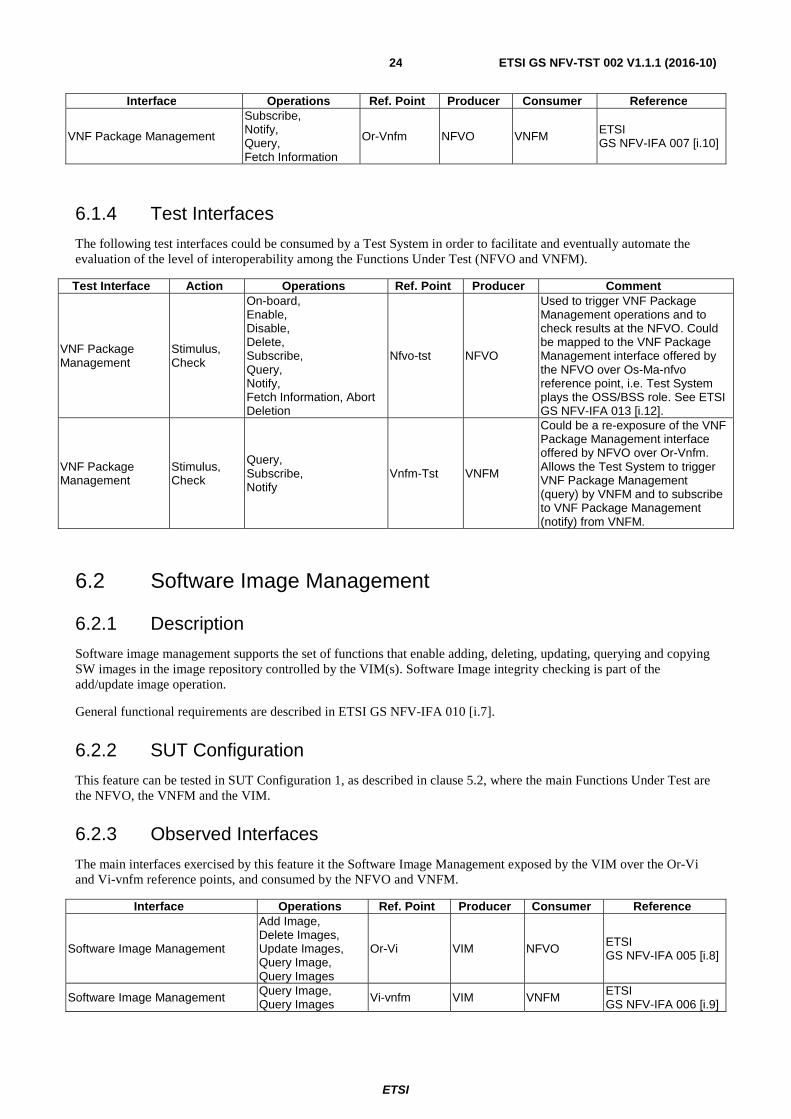
6.1.3 Observed Interfaces
The main interfaces exercised by this feature it the VNF Package Management exposed by the NFVO over the Or-Vnfm reference point, and consumed by the VNFM.
ETSI
ETSI GS NFV-TST 002 V1.1.1 (2016-10)24
Interface Operations Ref. Point Producer Consumer Reference
VNF Package Management
Subscribe, Notify, Query, Fetch Information
Or-Vnfm NFVO VNFM ETSI GS NFV-IFA 007 [i.10]
6.1.4 Test Interfaces
The following test interfaces could be consumed by a Test System in order to facilitate and eventually automate the evaluation of the level of interoperability among the Functions Under Test (NFVO and VNFM).
Test Interface Action Operations Ref. Point Producer Comment
VNF Package Management
Stimulus, Check
On-board, Enable, Disable, Delete, Subscribe, Query, Notify, Fetch Information, Abort Deletion
Nfvo-tst NFVO
Used to trigger VNF Package Management operations and to check results at the NFVO. Could be mapped to the VNF Package Management interface offered by the NFVO over Os-Ma-nfvo reference point, i.e. Test System plays the OSS/BSS role. See ETSI GS NFV-IFA 013 [i.12].
VNF Package Management
Stimulus, Check
Query, Subscribe, Notify
Vnfm-Tst VNFM
Could be a re-exposure of the VNF Package Management interface offered by NFVO over Or-Vnfm. Allows the Test System to trigger VNF Package Management (query) by VNFM and to subscribe to VNF Package Management (notify) from VNFM.
6.2 Software Image Management
6.2.1 Description
Software image management supports the set of functions that enable adding, deleting, updating, querying and copying SW images in the image repository controlled by the VIM(s). Software Image integrity checking is part of the add/update image operation.
General functional requirements are described in ETSI GS NFV-IFA 010 [i.7].
6.2.2 SUT Configuration
This feature can be tested in SUT Configuration 1, as described in clause 5.2, where the main Functions Under Test are the NFVO, the VNFM and the VIM.
6.2.3 Observed Interfaces
The main interfaces exercised by this feature it the Software Image Management exposed by the VIM over the Or-Vi and Vi-vnfm reference points, and consumed by the NFVO and VNFM.
Interface Operations Ref. Point Producer Consumer Reference
Software Image Management
Add Image, Delete Images, Update Images, Query Image, Query Images
Or-Vi VIM NFVO ETSI GS NFV-IFA 005 [i.8]
Software Image Management Query Image, Query Images Vi-vnfm VIM VNFM ETSI
GS NFV-IFA 006 [i.9]
ETSI
ETSI GS NFV-TST 002 V1.1.1 (2016-10)25
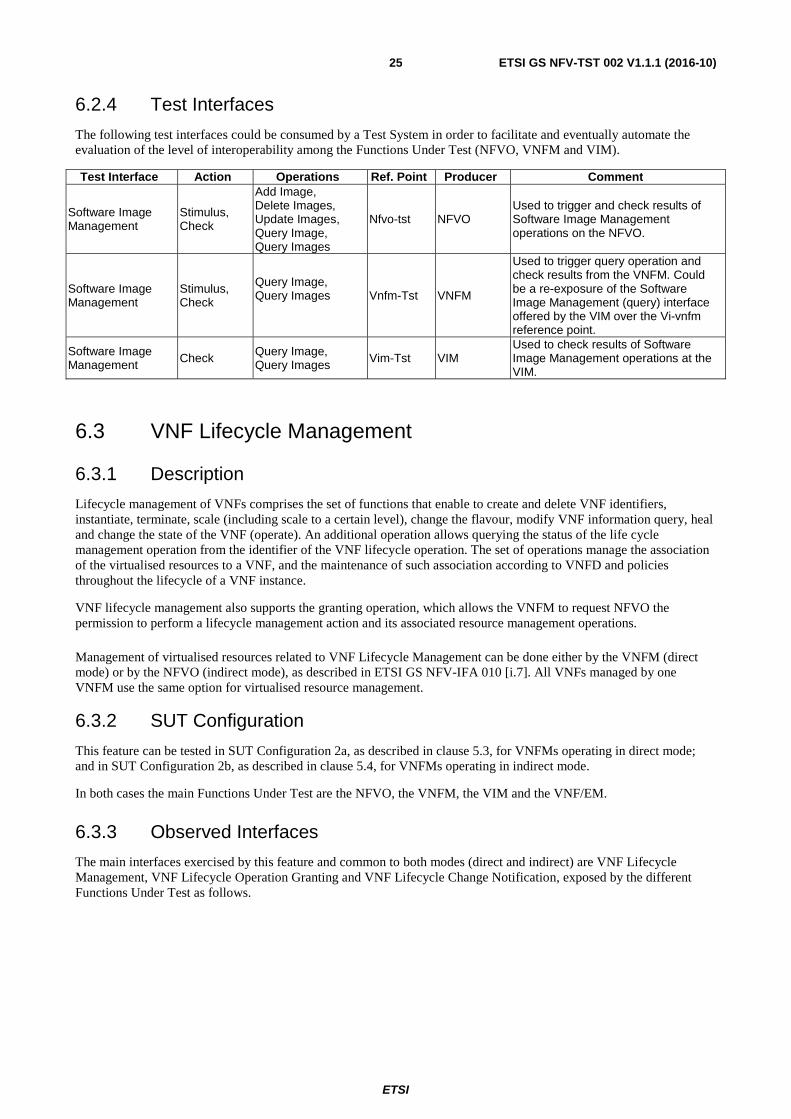
6.2.4 Test Interfaces
The following test interfaces could be consumed by a Test System in order to facilitate and eventually automate the evaluation of the level of interoperability among the Functions Under Test (NFVO, VNFM and VIM).
Test Interface Action Operations Ref. Point Producer Comment
Software Image Management
Stimulus, Check
Add Image, Delete Images, Update Images, Query Image, Query Images
Nfvo-tst NFVO Used to trigger and check results of Software Image Management operations on the NFVO.
Software Image Management
Stimulus, Check
Query Image, Query Images
Vnfm-Tst VNFM
Used to trigger query operation and check results from the VNFM. Could be a re-exposure of the Software Image Management (query) interface offered by the VIM over the Vi-vnfm reference point.
Software Image Management Check Query Image,
Query Images Vim-Tst VIM Used to check results of Software Image Management operations at the VIM.
6.3 VNF Lifecycle Management
6.3.1 Description
Lifecycle management of VNFs comprises the set of functions that enable to create and delete VNF identifiers, instantiate, terminate, scale (including scale to a certain level), change the flavour, modify VNF information query, heal and change the state of the VNF (operate). An additional operation allows querying the status of the life cycle management operation from the identifier of the VNF lifecycle operation. The set of operations manage the association of the virtualised resources to a VNF, and the maintenance of such association according to VNFD and policies throughout the lifecycle of a VNF instance.
VNF lifecycle management also supports the granting operation, which allows the VNFM to request NFVO the permission to perform a lifecycle management action and its associated resource management operations.
Management of virtualised resources related to VNF Lifecycle Management can be done either by the VNFM (direct mode) or by the NFVO (indirect mode), as described in ETSI GS NFV-IFA 010 [i.7]. All VNFs managed by one VNFM use the same option for virtualised resource management.
6.3.2 SUT Configuration
This feature can be tested in SUT Configuration 2a, as described in clause 5.3, for VNFMs operating in direct mode; and in SUT Configuration 2b, as described in clause 5.4, for VNFMs operating in indirect mode.
In both cases the main Functions Under Test are the NFVO, the VNFM, the VIM and the VNF/EM.
6.3.3 Observed Interfaces
The main interfaces exercised by this feature and common to both modes (direct and indirect) are VNF Lifecycle Management, VNF Lifecycle Operation Granting and VNF Lifecycle Change Notification, exposed by the different Functions Under Test as follows.

ETSI
ETSI GS NFV-TST 002 V1.1.1 (2016-10)26
Interface Operations Ref. Point Producer Consumer Reference VNF Lifecycle Operation Granting Grant VNF lifecycle Or-vnfm NFVO VNFM ETSI
GS NFV-IFA 007 [i.10]
VNF Lifecycle Management
Instantiate, Terminate, Scale, Scale to Level, Change Flavour, Query, Heal, Operate, Create Identifier, Delete Identifier, Modify Information, Get Operation Status
Or-vnfm VNFM NFVO ETSI GS NFV-IFA 007 [i.10]
VNF Lifecycle Change Notification
Subscribe, Notify Or-vnfm VNFM NFVO ETSI
GS NFV-IFA 007 [i.10]
VNF Lifecycle Management
Instantiate, Heal, Operate, Query, Terminate, Scale, Scale to Level, Create Identifier, Delete Identifier, Change Flavour, Modify Information, Get Operation Status
Ve-vnfm-em VNFM EM ETSI GS NFV-IFA 008 [i.11]
VNF Lifecycle Management
Heal, Scale Ve-vnfm-vnf VNFM VNF
ETSI GS NFV-IFA 008 [i.11]
VNF Lifecycle Change Notification
Subscribe, Notify Ve-vnfm-em VNFM EM ETSI
GS NFV-IFA 008 [i.11]
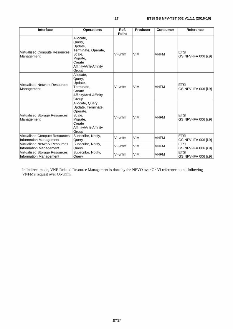
VNF Lifecycle Management functional area also exercises the Virtual Resource Management interfaces offered by the VIM. The observed reference points and interfaces depend on the VNFM's mode or operation.
In Direct Mode, VNF related Resource Management is done by the VNFM over Vi-vnfm reference point.
ETSI
ETSI GS NFV-TST 002 V1.1.1 (2016-10)27
Interface Operations Ref. Point
Producer Consumer Reference
Virtualised Compute Resources Management
Allocate, Query, Update, Terminate, Operate, Scale, Migrate, Create Affinity/Anti-Affinity Group
Vi-vnfm VIM VNFM ETSI GS NFV-IFA 006 [i.9]
Virtualised Network Resources Management
Allocate, Query, Update, Terminate, Create Affinity/Anti-Affinity Group
Vi-vnfm VIM VNFM ETSI GS NFV-IFA 006 [i.9]
Virtualised Storage Resources Management
Allocate, Query, Update, Terminate, Operate, Scale, Migrate, Create Affinity/Anti-Affinity Group
Vi-vnfm VIM VNFM ETSI GS NFV-IFA 006 [i.9]
Virtualised Compute Resources Information Management
Subscribe, Notify, Query Vi-vnfm VIM VNFM ETSI
GS NFV-IFA 006 [i.9] Virtualised Network Resources Information Management
Subscribe, Notify, Query Vi-vnfm VIM VNFM ETSI
GS NFV-IFA 006 [i.9] Virtualised Storage Resources Information Management
Subscribe, Notify, Query Vi-vnfm VIM VNFM ETSI
GS NFV-IFA 006 [i.9]
In Indirect mode, VNF-Related Resource Management is done by the NFVO over Or-Vi reference point, following VNFM's request over Or-vnfm.

ETSI
ETSI GS NFV-TST 002 V1.1.1 (2016-10)28
Interface Operations Ref. Point Producer Consumer Reference
Virtualised Compute Resources Management
Allocate, Query, Update, Terminate, Operate, Scale, Migrate, Create Affinity/Anti-Affinity Group
Or-vnfm NFVO VNFM ETSI GS NFV-IFA 007 [i.10]
Virtualised Network Resources Management
Allocate, Query, Update, Terminate, Create Affinity/Anti-Affinity Group
Or-vnfm NFVO VNFM ETSI GS NFV-IFA 007 [i.10]
Virtualised Storage Resources Management
Allocate, Query, Update, Terminate, Operate, Scale, Migrate, Create Affinity/Anti-Affinity Group
Or-vnfm NFVO VNFM ETSI GS NFV-IFA 007 [i.10]
Virtualised Compute Resources Management
Allocate, Query, Update, Terminate, Operate, Scale, Migrate, Create Affinity/Anti-Affinity Group
Or-vi VIM NFVO ETSI GS NFV-IFA 005 [i.8]
Virtualised Network Resources Management
Allocate, Query, Update, Terminate, Create Affinity/Anti-Affinity Group
Or-vi VIM NFVO ETSI GS NFV-IFA 005 [i.8]
Virtualised Storage Resources Management
Allocate, Query, Update, Terminate, Operate, Scale, Migrate, Create Affinity/Anti-Affinity
Or-vi VIM NFVO ETSI GS NFV-IFA 005 [i.8]
Virtualised Compute Resources Information Management
Subscribe, Notify, Query
Or-vi VIM NFVO ETSI GS NFV-IFA 005 [i.8]
Virtualised Network Resources Information Management
Subscribe, Notify, Query
Or-vi VIM NFVO ETSI GS NFV-IFA 005 [i.8]
Virtualised Storage Resources Information Management
Subscribe, Notify, Query
Or-vi VIM NFVO ETSI GS NFV-IFA 005 [i.8]
6.3.4 Test Interfaces
The following test interfaces could be consumed by a Test System in order to facilitate and eventually automate the evaluation of the level of interoperability among the Functions Under Test (NFVO, VNFM and VIM).

ETSI
ETSI GS NFV-TST 002 V1.1.1 (2016-10)29
Test Interface Action Operations Ref. Point Producer Comment
VNF Lifecycle Management
Stimulus, Check
Instantiate, Terminate, Scale, Scale to Level, Query, Heal, Operate
Nfvo-tst NFVO
Used to trigger VNF Life Cycle Management operations and to check results at the NFVO.
VNF Lifecycle Change Notification Check Subscribe,
Notify Nfvo-tst NFVO
Used by the Test System to subscribe to VNF LC Notifications from the NFVO.
VNF Lifecycle Management Stimulus Scale,
Heal Vnf-Tst VNF
Used to trigger VNF Lifecycle Management (scale, heal) operations at the VNF. Could be a re-exposure of the VNF Lifecycle Management interface at the Ve-Vnfm-vnf reference point. See ETSI GS NFV-IFA 008 [i.11].
VNF Lifecycle Management
Stimulus Check
Instantiate, Terminate, Query, Scale, Scale to Level Heal, Operate, Change Flavour, Create Identifier, Delete Identifier, Modify Information
Em-Tst EM
Used to trigger VNF Lifecycle Management operations and check results at the EM. Could be a re-exposure of the VNF Lifecycle Management interface at the Ve-Vnfm-em reference point. See ETSI GS NFV-IFA 008 [i.11].
VNF Lifecycle Change Notification Check
Subscribe, Notify Em-Tst EM
Used by the Test System to subscribe to VNF LC Notifications from the EM. Could be a re-exposure of the VNF Lifecycle Change Notification interface offered by the VNFM over Ve-Vnfm-em reference point. See ETSI GS NFV-IFA 008 [i.11].
VNF Lifecycle Management
Check Query Vnfm-tst VNFM
Used to check results of VNF Lifecycle Management operations at the VNFM.
VNF Lifecycle Change Notification Check
Subscribe, Notify Vnfm-tst VNFM
Used by the Test System to subscribe to VNF LC Notifications from the VNFM.
Virtualised Compute Resources Management Check Query Vim-tst VIM
Used by the Test System to query Virtualised Compute Resource Management information at the VIM. Could be a re-exposure of the Virtualised Compute Resource Management interface offered by the VIM over the Or-Vi or Vi-vnfm reference points.

ETSI
ETSI GS NFV-TST 002 V1.1.1 (2016-10)30
Test Interface Action Operations Ref. Point Producer Comment
Virtualised Network Resources Management Check Query Vim-tst VIM
Used by the Test System to query Virtualised Network Resource Management information at the VIM. Could be a re-exposure of the Virtualised Network Resource Management interface offered by the VIM over the Or-Vi or Vi-vnfm reference points.
Virtualised Storage Resources Management Check Query Vim-tst VIM
Used by the Test System to query Virtualised Storage Resource Management information at the VIM. Could be a re-exposure of the Virtualised Storage Resource Management interface offered by the VIM over the Or-Vi or Vi-vnfm reference points.
Virtualised Compute Information Management Check Query Vim-tst VIM
Used by the Test System to query information about consumable Virtualised Compute Resources at the VIM. Could be a re-exposure of the Virtualised Compute Information Management interface offered by the VIM over the Or-Vi or Vi-vnfm reference points.
Virtualised Network Information Management Check Query Vim-tst VIM
Used by the Test System to query information about consumable Virtualised Network Resources at the VIM. Could be a re-exposure of the Virtualised Network Information Management interface offered by the VIM over the Or-Vi or Vi-vnfm reference points.
Virtualised Storage Information Management Check Query Vim-tst VIM
Used by the Test System to query information about consumable Virtualised Storage Resources at the VIM. Could be a re-exposure of the Virtualised Storage Information Management interface offered by the VIM over the Or-Vi or Vi-vnfm reference points.
Virtualised Compute Information Management
Check Query Nfvi-tst NFVI Used by the Test System to query Virtual Compute information at the NFVI.
Virtualised Network Information Management Check Query Nfvi-tst NFVI
Used by the Test System to query Virtual Network information at the NFVI.
Virtualised Storage Information Management Check Query Nfvi-tst NFVI
Used by the Test System to query Virtual Storage information at the NFVI.
ETSI
ETSI GS NFV-TST 002 V1.1.1 (2016-10)31
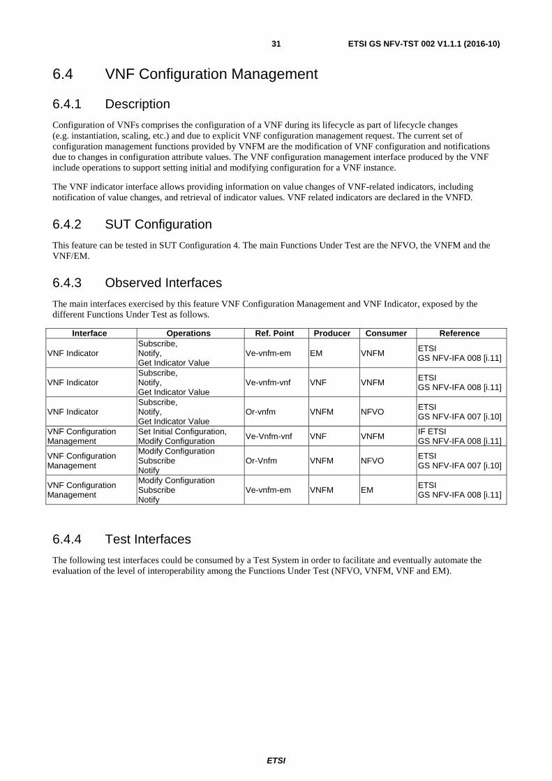
6.4 VNF Configuration Management
6.4.1 Description
Configuration of VNFs comprises the configuration of a VNF during its lifecycle as part of lifecycle changes (e.g. instantiation, scaling, etc.) and due to explicit VNF configuration management request. The current set of configuration management functions provided by VNFM are the modification of VNF configuration and notifications due to changes in configuration attribute values. The VNF configuration management interface produced by the VNF include operations to support setting initial and modifying configuration for a VNF instance.
The VNF indicator interface allows providing information on value changes of VNF-related indicators, including notification of value changes, and retrieval of indicator values. VNF related indicators are declared in the VNFD.
6.4.2 SUT Configuration
This feature can be tested in SUT Configuration 4. The main Functions Under Test are the NFVO, the VNFM and the VNF/EM.
6.4.3 Observed Interfaces
The main interfaces exercised by this feature VNF Configuration Management and VNF Indicator, exposed by the different Functions Under Test as follows.
Interface Operations Ref. Point Producer Consumer Reference
VNF Indicator Subscribe, Notify, Get Indicator Value
Ve-vnfm-em EM VNFM ETSI GS NFV-IFA 008 [i.11]
VNF Indicator Subscribe, Notify, Get Indicator Value
Ve-vnfm-vnf VNF VNFM ETSI GS NFV-IFA 008 [i.11]
VNF Indicator Subscribe, Notify, Get Indicator Value
Or-vnfm VNFM NFVO ETSI GS NFV-IFA 007 [i.10]
VNF Configuration Management
Set Initial Configuration, Modify Configuration
Ve-Vnfm-vnf VNF VNFM IF ETSI GS NFV-IFA 008 [i.11]
VNF Configuration Management
Modify Configuration Subscribe Notify
Or-Vnfm VNFM NFVO ETSI GS NFV-IFA 007 [i.10]
VNF Configuration Management
Modify Configuration Subscribe Notify
Ve-vnfm-em VNFM EM ETSI GS NFV-IFA 008 [i.11]
6.4.4 Test Interfaces
The following test interfaces could be consumed by a Test System in order to facilitate and eventually automate the evaluation of the level of interoperability among the Functions Under Test (NFVO, VNFM, VNF and EM).

ETSI
ETSI GS NFV-TST 002 V1.1.1 (2016-10)32
Test Interface Action Operations Ref. Point Producer Comment
VNF Indicator Stimulus Check
Subscribe, Notify, Get Indicator Value
Nfvo-tst NFVO
Used by the Test System to subscribe to VNF Indicator Notifications and to trigger queries on specific indicators at the NFVO. Could be a re-exposure of the VNF Indicator interfaces offered by the VNFM over the Or-Vnfm reference point. See ETSI GS NFV-IFA 007 [i.10].
VNF Indicator Check Subscribe, Notify, Get Indicator Value
Vnfm-tst VNFM
Used by the Test System to subscribe to VNF Indicator Notifications from the EM and/or VNF and to trigger queries on specific indicators at the VNFM. Could be a re-exposure of the VNF Indicator interface offered by the VNFM over the Or-Vnfm reference point. See ETSI GS NFV-IFA 007 [i.10].
VNF Configuration Management Stimulus Set Initial Configuration Vnfm-tst VNFM
Used by the Test System to trigger setInitialConfiguration on the VNF from the VNFM. Could be a re-exposure of the VNF Configuration Management interface offered by the VNF over the Ve-Vnfm-Vnf reference point. See ETSI GS NFV-IFA 008 [i.11].
VNF Configuration Management Stimulus Modify Configuration Em-tst EM
Used by the Test System to trigger ModifyConfiguration on the VNF from the EM (and through the VNFM). Could be a re-exposure of the VNF Configuration Management interface offered by the VNF/VNFM over the Ve-Vnfm reference points. See ETSI GS NFV-IFA 008 [i.11].
VNF Configuration Management Stimulus Modify Configuration Nfvo-tst NFVO
Used by the Test System to trigger ModifyConfiguration on the VNF from the NFVO (and through the VNFM). Could be a re-exposure of the VNF Configuration Management interface offered by the VNFM over the Or-Vnfm reference point. See ETSI GS NFV-IFA 007 [i.10].
VNF Configuration Management Check Query Vnf-Tst VNF
Used to query VNF Configuration details at the VNF.

ETSI
ETSI GS NFV-TST 002 V1.1.1 (2016-10)33
6.5 VNF Fault Management
6.5.1 Description
Fault management of VNFs enables the provisioning of VNF fault information (e.g. network function configuration failures, communication failures between software modules, etc.) to a consumer functional block. The fault information is used to facilitate fault management operations performed by functional blocks other than the VNF.
VNF fault management supports the retrieval of on-demand fault information, as well as fault notifications by means of subscription.
Faults can be originated in the NFVI, the VIM or the VNFM as a result of correlating faults received or as a result of threshold crossing. Each layer can provide notifications.
Notifications are captured on the consumer of the interfaces where notifications are sent.
General functional requirements for fault management are described in ETSI GS NFV-IFA 010 [i.7].
6.5.2 SUT Configuration
This feature can be tested in SUT Configuration 2a or 2b, as described in clause 5.3. In both cases the main Functions Under Test are the NFVO, the VNFM, the VIM and the EM.
6.5.3 Observed Interfaces
The main interfaces exercised by this feature it the VNF Fault Management exposed by the VNFM over the Or-Vnfm reference point, and the Ve-Vnfm-Em reference point.
Interface Operations Ref. Point Producer Consumer Reference
VNF Fault Management Subscribe, Notify, Get Alarm List
Or-Vnfm VNFM NFVO ETSI GS NFV-IFA 007 [i.10]
VNF Fault Management
Subscribe, Notify, Get Alarm List Ve-vnfm-em VNFM EM
ETSI GS NFV-IFA 008 [i.11]
Virtualised Resources Fault Management
Subscribe, Notify, Get Alarm List Vi-vnfm VIM VNFM ETSI
GS NFV-IFA 006 [i.9]
6.5.4 Test Interfaces
The following test interfaces could be consumed by a Test System in order to facilitate and eventually automate the evaluation of the level of interoperability among the Functions Under Test (NFVO and VNFM).

ETSI
ETSI GS NFV-TST 002 V1.1.1 (2016-10)34
Test Interface Action Operations Ref. Point Producer Comment Virtualised Resources Fault Management Stimulus Trigger Nfvi-tst NFVI Used to trigger faults in the
NFVI.
Virtualised Resources Fault Management
Stimulus, Check
Trigger, Subscribe, Notify, Get Alarm List
Vim-tst VIM
Used to trigger faults and check results in the VIM. Could be partially mapped to the Virtualised Resources Fault Management interface offered by the VIM on the Vi-vnfm reference point.
Virtualised Resources Fault Management Check Subscribe, Notify,
Get Alarm List Vnfm-tst VNFM
Used to check Virtualised Resources faults received in the VNFM. Could be a re-exposure of the Virtualised Resources Fault Management interface offered by the VIM on the Vi-vnfm reference point.
VNF Fault Management Stimulus, check
Trigger, Subscribe, Notify, Get Alarm List
Vnfm-tst VNFM
Used to trigger faults and check results at the VNFM. Could be partially mapped to the VNF Fault Management interface offered by the VNFM on the Or-vnfm or Ve-vnfm-em reference points.
VNF Fault Management Check Subscribe, Notify, Get Alarm List Em-tst EM
Used to check VNF faults received in the EM. Could be a re-exposure of the VNF Fault Management interface offered by the VNFM on the Ve-vnfm-em reference point.
VNF Fault Management Check Subscribe, Notify, Get Alarm List
Nfvo-tst NFVO
Used to check VNF faults received in the NFVO. Could be a re-exposure of the VNF Fault Management interface offered by the VNFM on the Or-vnfm reference point.
6.6 VNF Performance Management
6.6.1 Description
Performance management of VNFs enables the provisioning of VNF performance information related to the behaviour of the VNF. The performance information is used to facilitate performance management operations made by functional blocks other than the VNF.
VNF performance management supports the collection of measurement results as well as the notifications performed through subscriptions.
Performance management supports alarms through threshold crossings. A performance management job and a threshold have to be created first in order to enable the performance alarm.
The general requirements are described in ETSI GS NFV-IFA 010 [i.7].
6.6.2 SUT Configuration
This feature can be tested in SUT Configuration 2a or 2b, as described in clause 5.3 and 5.4, where the main Functions Under Test are NFVO, VNFM, VIM, EM and VNF.
6.6.3 Observed Interfaces
The main interfaces exercised by this feature it are the VNF Performance Management and Virtualised Resources Performance Management.

ETSI
ETSI GS NFV-TST 002 V1.1.1 (2016-10)35
Interface Operations Ref. Point Producer Consumer Reference
VNF Performance Management
Create PM Job, Delete PM Job, Query PM Job, Subscribe, Notify, Create Threshold, Delete Threshold, Query Threshold
Or-Vnfm VNFM NFVO ETSI GS NFV-IFA 007 [i.10]
Virtualised Resources Performance Management
Create PM Job, Delete PM Job, Query PM Job, Subscribe, Notify, Create Threshold, Delete Threshold, Query Threshold
Vi-vnfm VIM VNFM ETSI GS NFV-IFA 006 [i.9]
VNF Performance Management
Create PM Job, Delete PM Job, Query PM Job, Subscribe, Notify, Create Threshold, Delete Threshold, Query Threshold
Ve-Vnfm-em VNFM EM ETSI GS NFV-IFA 008 [i.11]
6.6.4 Test Interfaces
The following test interfaces could be consumed by a Test System in order to facilitate and eventually automate the evaluation of the level of interoperability among the Functions Under Test.
Note that alarms can be triggered in NFVI, in VIM or in VNFM as a result of correlating alarms received or as a result of threshold crossing. Each layer can provide notifications.
Note that notifications should be captured on the consumer of the interfaces where notifications are sent.

ETSI
ETSI GS NFV-TST 002 V1.1.1 (2016-10)36
Test Interface Action Operations Ref. Point Producer Comment
VNF Performance Management
Stimulus, Check
Create PM Job, Delete PM Job, Query PM Job, Subscribe, Notify, Create Threshold, Delete Threshold, Query Threshold
Nfvo-Tst NFVO
This is an additional test interface on the NFVO, corresponds to the same-named interface produced by the VNFM over the Or-Vnfm reference point. See ETSI GS NFV-IFA 007 [i.10].
VNF Performance Management
Stimulus, Check
Create PM Job, Delete PM Job, Query PM Job, Subscribe, Notify, Create Threshold, Delete Threshold, Query Threshold
Vnfm-Tst VNFM
This interface corresponds to the same-named interface produced by the VNFM over the Or-Vnfm reference point. See ETSI GS NFV-IFA 007 [i.10].
VNF Performance Management Stimulus Trigger Em-Tst EM
Used to trigger performance measurement change in the VNF level. Performance data may be injected or induced via other means, such as generating a specific workload that matches the tested performance metric.
Virtualised Resources Performance Management
Stimulus, Check
Trigger, Subscribe, Notify, Query PM Job, Query Threshold
Vim-Tst VIM
This interface corresponds to the same-named interface produced by the VIM over the Or-Vi and Vi-Vnfm reference points. See ETSI GS NFV-IFA 005 [i.8] and ETSI GS NFV-IFA 006 [i.9].
Virtualised Resources Performance Management
Stimulus, Check
Subscribe, Notify, Query PM Job, Query Threshold
Vnfm-Tst VNFM
This interface corresponds to the same-named interface produced by the VNFM over the Or-Vnfm reference points. See ETSI GS NFV-IFA 007 [i.10].
Virtualised Resources Performance Management
Stimulus Trigger Nfvi-Tst NFVI
Used to trigger performance measurement change in the NFVI level. Performance data may be injected or induced via other means, such as generating a specific workload that matches the tested performance metric.
6.7 Network Service Lifecycle Management
6.7.1 Description
Lifecycle management of Network Services (NS) is performed by the NFV Orchestrator. Network Service Orchestration coordinates the lifecycle of VNFs that jointly realize a Network Service. This includes managing the associations between different VNFs, and if applicable between VNFs and PNFs, the topology of the Network Service, and the VNFFGs associated with the NS. In order to fulfil its responsibilities, the NFV Orchestrator functions consume services exposed by other functional blocks (e.g. VNFM and VIM).
The set of functions include NS Descriptor instantiation, scaling, update and termination of NS instances as well as the creation, deletion, query, and update of VNF Forwarding Graphs associated to a NS.
Both reservation-based and quota-based resource management are supported.
Other functions, such as runtime notifications related to the state of a NS instance, and querying the status of a NS instance are also supported.
The general requirements are described in ETSI GS NFV-IFA 010 [i.7].

ETSI
ETSI GS NFV-TST 002 V1.1.1 (2016-10)37
6.7.2 SUT Configuration
This feature can be tested in SUT Configuration 3, as described in clause 5.5, where the main Functions Under Test are NFVO, VNFM and VIM.
6.7.3 Observed Interfaces
The main interfaces exercised by this feature it are the various interfaces relating to Virtualised Network Resources, as well as Network Forwarding Path Management and VNF Lifecycle Management.
Interface Operations Ref. Point Producer Consumer Reference
Virtualised Network Resources Reservation Management
Create, Query, Update, Terminate
Or-Vi VIM NFVO ETSI GS NFV-IFA 005 [i.8]
Virtualised Network Resources Quota Management
Create, Query, Update, Terminate
Or-Vi VIM NFVO ETSI GS NFV-IFA 005 [i.8]
Virtualised Network Resources Management
Allocate, Query, Update, Terminate, Create Affinity/ Anti-Affinity Group
Or-Vi VIM NFVO ETSI GS NFV-IFA 005 [i.8]
Virtualised Network Resources Information Management
Subscribe, Notify, Query
Or-Vi VIM NFVO ETSI GS NFV-IFA 005 [i.8]
Virtualised Network Resources Capacity Management
Subscribe, Notify, Query Network Capacity, Query NFVI-PoP Network
Or-Vi VIM NFVO ETSI GS NFV-IFA 005 [i.8]
VNF Lifecycle Management
Instantiate, Terminate, Scale, Scale to Level, Change Flavour, Query, Heal, Operate, Create Identifier, Delete Identifier, Modify Information, Get Operation Status
Or-Vnfm VNFM NFVO ETSI GS NFV-IFA 007 [i.10]
Network Forwarding Path Management
Create, Query, Delete, Change
Or-Vi VIM NFVO ETSI GS NFV-IFA 005 [i.8]
6.7.4 Test Interfaces
The following test interfaces could be consumed by a Test System in order to facilitate and eventually automate the evaluation of the level of interoperability among the Functions Under Test.
The high-level Network Service interfaces follow the semantics of the Os-Ma-Nfvo interfaces with the same name, as described in ETSI GS NFV-IFA 013 [i.12].
Operations on network services may trigger operations on VNF, but not always. For example, instantiating an NS is likely to trigger operations to instantiate VNFs, but operations on the NFP (Network Forwarding Path) may only concern NS.
It is unlikely that NS lifecycle management operations will allocate directly compute or storage resources, so these micro-services will be used for VNF lifecycle management. Network Services might be used by both. NFP management will be used only for NS lifecycle management.

ETSI
ETSI GS NFV-TST 002 V1.1.1 (2016-10)38
Test Interface Action Operations Ref. Point
Producer Comment
NS Lifecycle Management
Stimulus, Check
Instantiate, Terminate, Scale, Scale to Level, Change Flavour, Query, Heal, Operate, Create Identifier, Delete Identifier, Modify Information, Get Operation Status
Nfvo-Tst NFVO
This is an additional test interface on the NFVO, corresponds to the same-named interface produced by the NFVO over the Os-Ma-nfvo reference point. See ETSI GS NFV-IFA 013 [i.12].
NS Lifecycle Change Notifications
Stimulus, Check
Subscribe, Notify Vnfm-Tst VNFM
This is an additional test interface on the NFVO, corresponds to the same-named interface produced by the NFVO over the Os-Ma-nfvo reference point. See ETSI GS NFV-IFA 013 [i.12].
VNF Lifecycle Management Check Query Vnfm-Tst VNFM
Used to check VNF-level status following corresponding NS operation. See note.
Virtualised Network Resources Reservation Management
Check Query Vim-Tst VIM
Used to check virtual resources reservation status following corresponding NS operation.
Virtualised Network Resources Management
Check Query Vim-Tst VIM
Used to check virtual resources status following corresponding NS operation.
Virtualised Network Resources Information Management
Check Query Vim-Tst VIM
Used to check virtual resources information following corresponding NS operation.
Virtualised Network Resources Capacity Management
Check Query Network Capacity, Query NFVI-PoP Network Vim-Tst VIM
Used to check virtual resources capacity following corresponding NS operation.
Virtualised Compute Resources Capacity Management
Check Query, Query Resource Zone, Query NFVI-PoP Compute
Vim-Tst VIM
Used to check virtual resources capacity following corresponding NS operation.
Virtualised Storage Resources Capacity Management
Check
Query, Query Storage Capacity, Query NFVI-PoP, Query Resource Zone
Vim-Tst VIM
Used to check virtual resources capacity following corresponding NS operation.
Network Forwarding Path Management Check Query Vim-Tst VIM
Used to check network forwarding path status following corresponding NS operation.
NOTE: NS Lifecycle Management (Query) would be needed first to get the list of VNFs that are part of a particular NS.

ETSI
ETSI GS NFV-TST 002 V1.1.1 (2016-10)39
6.8 Network Service Fault Management
6.8.1 Description
NS fault management comprises the provisioning of fault information on NSs. including the fault information resulting from the processing of information received from other functional blocks, as well as forwarding of fault information after correlation to the Network Service instance affected. These information facilitate the fault management operation on NSs performed by OSS.
On-demand retrieval of NS fault information is supported through the Get Alarm List operation. Provisioning of fault notifications through subscription is supported through the Subscriber/Notify operations.
Fault information on a given NS results from either a collected virtualised resource fault impacting the connectivity of the Network Service instance or a VNF alarm (resulting from a virtualised resource fault) issued by the VNFM for a VNF that is part of this Network Service instance.
The general requirements are described in ETSI GS NFV-IFA 010 [i.7].
6.8.2 SUT Configuration
This feature can be tested in SUT Configuration 3, as described in clause 5.5, where the main Functions Under Test are NFVO, VNFM, VIM and VNF.
6.8.3 Observed Interfaces
The main interfaces exercised by this feature it are the VNF Fault Management and Virtualised Resource Fault Management.
Interface Operations Ref. Point Producer Consumer Reference
VNF Fault Management Subscribe, Notify, Get Alarm List
Or-Vnfm VNFM NFVO ETSI GS NFV-IFA 007 [i.10]
Virtualised Resource Fault Management
Subscribe, Notify, Get Alarm List
Or-Vi VIM NFVO ETSI GS NFV-IFA 005 [i.8]
6.8.4 Test Interfaces
The following test interfaces could be consumed by a Test System in order to facilitate and eventually automate the evaluation of the level of interoperability among the Functions Under Test.
Network Service faults resulting from Virtual Resources faults and/or VNF faults will be exposed at NFVO.
When VNF related resource management is done by NFVO (i.e. indirect mode), the NFVO will receive the VNF-related Virtualised Resource Fault notifications.

ETSI
ETSI GS NFV-TST 002 V1.1.1 (2016-10)40
Test Interface Action Operations Ref. Point Producer Comment
Network Service Fault Management
Stimulus, Check
Subscribe, Notify, Get Alarm List
Nfvo-Tst NFVO
This is an additional test interface on the NFVO, corresponds to the same-named interface produced by the NFVO over the Os-Ma-nfvo reference point. See ETSI GS NFV-IFA 013 [i.12].
VNF Fault Management
Stimulus, Check
Subscribe, Notify, Get Alarm List, Trigger
Vnfm-Tst VNFM Used to inject faults and/or check fault status at the VNF level to verify corresponding NS fault propagation.
Virtualised Resource Fault Management
Stimulus, Check
Subscribe, Notify, Get Alarm List, Trigger
Vim-Tst VIM Used to inject faults and/or check fault status at the VIM level to verify corresponding NS fault propagation.
Virtualised Resource Fault Management
Stimulus Trigger Nfvi-Tst NFVI Used to inject faults and/or check fault status at the NFVI level to verify corresponding NS fault propagation.
6.9 Network Service Performance Management
6.9.1 Description
NS performance management comprises the provisioning of NS-related performance information. NS metrics might be calculated from measurement results coming from the underlying layers including metrics related to network performance and resource consumption.
On-demand retrieval of NS performance information is supported through the Get Alarm List operation. Provisioning of performance notifications through subscription is supported through the Subscriber/Notify operations. Monitoring of performance metrics is provisioned by creating a PM job. Threshold crossing alarms are provisioned by creating a threshold. Note that creating a threshold does not trigger collection of metrics. In order for the threshold to be active, there should be a PM job collecting the needed metric for the selected entities.
Performance information on a given Network Service results from either collected performance information of the virtualised resources impacting the connectivity of this Network Service instance or VNF performance information issued by the VNFM for the VNFs that is part of this Network Service instance. The latter performance information also results from collected performance information of the virtualised resources that are mapped to this VNF instance.
6.9.2 SUT Configuration
This feature can be tested in SUT Configuration 3, as described in clause 5.5, where the main Functions Under Test are NFVO, VNFM, VIM and VNF.
6.9.3 Observed Interfaces
The main interfaces exercised by this feature it are the VNF Performance Management and Virtualised Resource Performance Management.
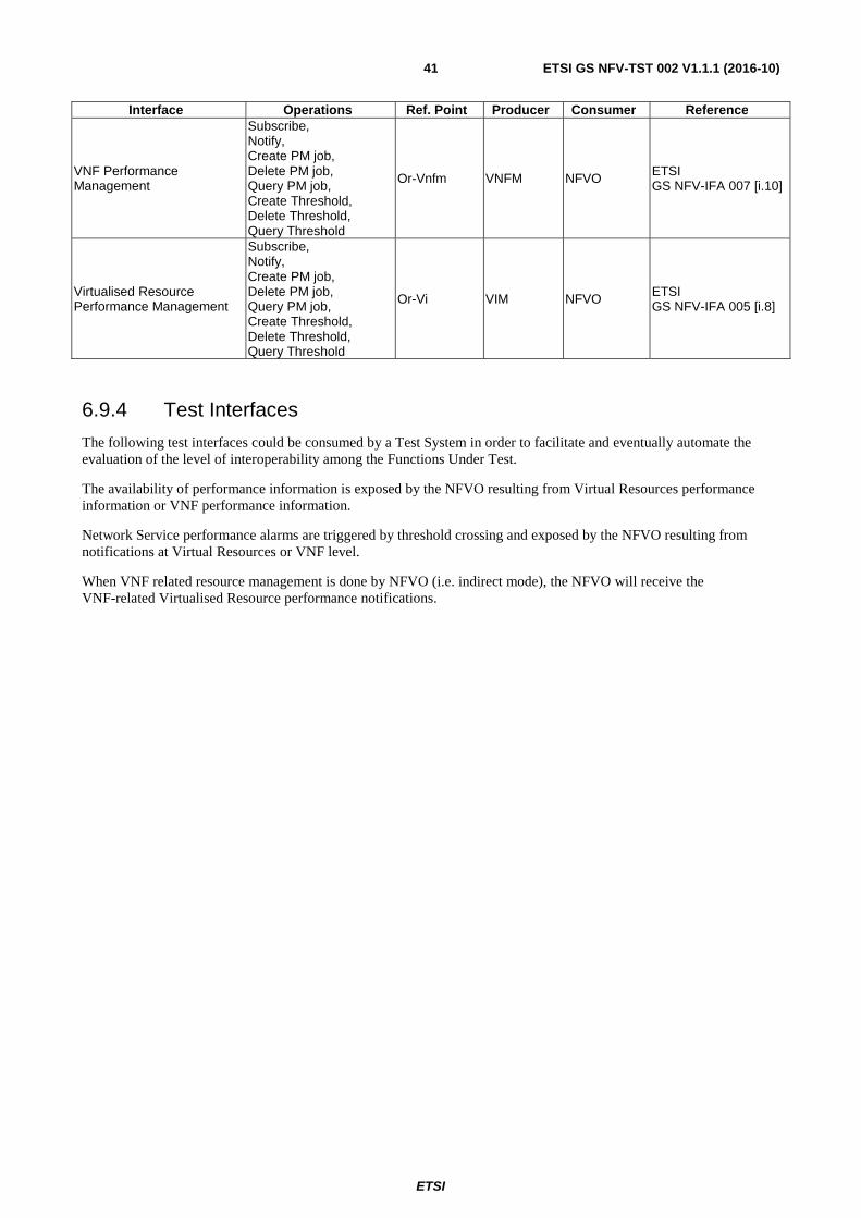
ETSI
ETSI GS NFV-TST 002 V1.1.1 (2016-10)41
Interface Operations Ref. Point Producer Consumer Reference
VNF Performance Management
Subscribe, Notify, Create PM job, Delete PM job, Query PM job, Create Threshold, Delete Threshold, Query Threshold
Or-Vnfm VNFM NFVO ETSI GS NFV-IFA 007 [i.10]
Virtualised Resource Performance Management
Subscribe, Notify, Create PM job, Delete PM job, Query PM job, Create Threshold, Delete Threshold, Query Threshold
Or-Vi VIM NFVO ETSI GS NFV-IFA 005 [i.8]
6.9.4 Test Interfaces
The following test interfaces could be consumed by a Test System in order to facilitate and eventually automate the evaluation of the level of interoperability among the Functions Under Test.
The availability of performance information is exposed by the NFVO resulting from Virtual Resources performance information or VNF performance information.
Network Service performance alarms are triggered by threshold crossing and exposed by the NFVO resulting from notifications at Virtual Resources or VNF level.
When VNF related resource management is done by NFVO (i.e. indirect mode), the NFVO will receive the VNF-related Virtualised Resource performance notifications.
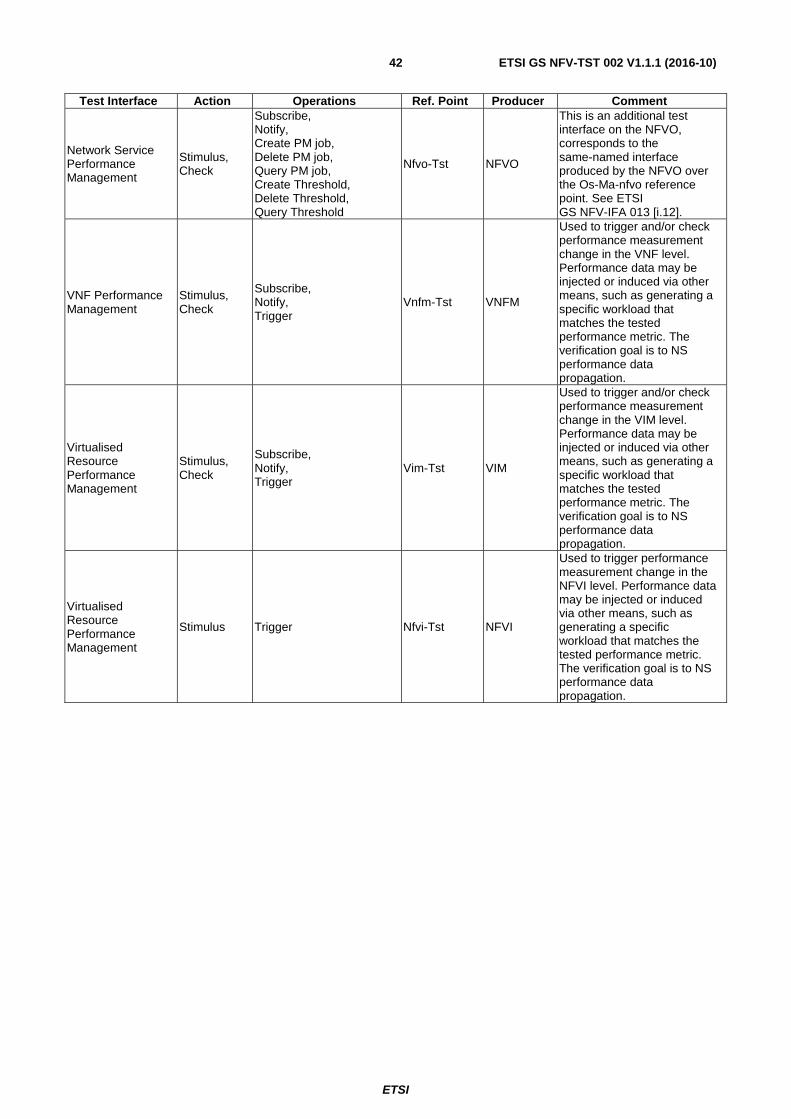
ETSI
ETSI GS NFV-TST 002 V1.1.1 (2016-10)42
Test Interface Action Operations Ref. Point Producer Comment
Network Service Performance Management
Stimulus, Check
Subscribe, Notify, Create PM job, Delete PM job, Query PM job, Create Threshold, Delete Threshold, Query Threshold
Nfvo-Tst NFVO
This is an additional test interface on the NFVO, corresponds to the same-named interface produced by the NFVO over the Os-Ma-nfvo reference point. See ETSI GS NFV-IFA 013 [i.12].
VNF Performance Management
Stimulus, Check
Subscribe, Notify, Trigger
Vnfm-Tst VNFM
Used to trigger and/or check performance measurement change in the VNF level. Performance data may be injected or induced via other means, such as generating a specific workload that matches the tested performance metric. The verification goal is to NS performance data propagation.
Virtualised Resource Performance Management
Stimulus, Check
Subscribe, Notify, Trigger
Vim-Tst VIM
Used to trigger and/or check performance measurement change in the VIM level. Performance data may be injected or induced via other means, such as generating a specific workload that matches the tested performance metric. The verification goal is to NS performance data propagation.
Virtualised Resource Performance Management
Stimulus Trigger Nfvi-Tst NFVI
Used to trigger performance measurement change in the NFVI level. Performance data may be injected or induced via other means, such as generating a specific workload that matches the tested performance metric. The verification goal is to NS performance data propagation.

ETSI
ETSI GS NFV-TST 002 V1.1.1 (2016-10)43
Annex A (informative): NFV IFS Pro-forma example
Functional Block VIM Functional Area VNF Life Cycle Management/NS Life Cycle Management Option Resource Commitment Model References ETSI GS NFV-IFA 010 V2.1.1 [i.7] Options Id Feature Status Support Details VIM_RCM_RESERVATION Reservation M Vim.Rm.001 VIM_RCM_QUOTA_BASED Quota Based M Vim.Rm.001 VIM_RCM_ON_DEMAND On-demand M Vim.Rm.001
Functional Block VIM Functional Area Software Image Management Observed Reference Point Or-Vi Observed Interface Software Image Management Producer/Consumer Producer References ETSI GS NFV-IFA 005 V2.1.1 [i.8] Interoperability Features Id Feature Status Support Details VIM_SWIM_ADD_IM Add Image M VIM_SWIM_QUERY_IMS Query Images M VIM_SWIM_QUERY_IM Query Image M VIM_SWIM_UPDATE_IM Update Images M VIM_SWIM_DELETE_IM Delete Images M Test Interfaces Id Feature Status Support Details TST_VIM_SWIM_QUERY_IMS Query Images O TST_VIM_SWIM_QUERY_IM Query Image O
Functional Block VIM Functional Area VNF Life Cycle Management Observed Reference Point Or-Vi Observed Interface Virtualised Compute Resources Management Producer/Consumer Producer References ETSI GS NFV-IFA 005 V2.1.1 [i.8] Interoperability Features Id Feature Status Support Details
VIM_VCRM_ALLOC_VCR Allocate Virtualised Compute Resource M
VIM_VCRM_QUERY_VCR Query Virtualised Compute Resource M
VIM_VCRM_UPDATE_VCR Update Virtualised Compute Resource M
VIM_VCRM_TERMINATE_VCR Terminate Virtualised Compute Resource M
VIM_VCRM_OPERATE_VCR Operate Virtualised Compute Resource
M
VIM_VCRM_SCALE_VCR Scale Virtualised Compute Resource M
VIM_VCRM_MIGRATE_VCR Migrate Virtualised Compute Resource M
Test Interfaces Id Feature Status Support Details TST_VIM_VCRM_QUERY_VCR Query Virtualised Compute Resource O
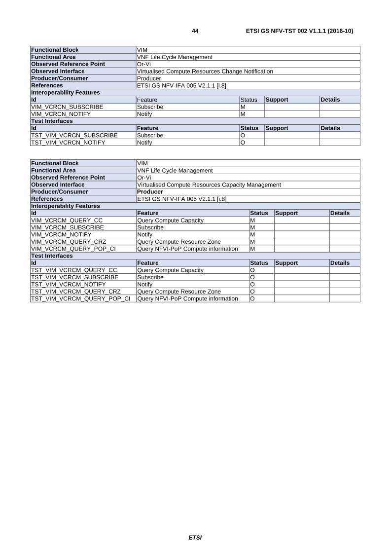
ETSI
ETSI GS NFV-TST 002 V1.1.1 (2016-10)44
Functional Block VIM Functional Area VNF Life Cycle Management Observed Reference Point Or-Vi Observed Interface Virtualised Compute Resources Change Notification Producer/Consumer Producer References ETSI GS NFV-IFA 005 V2.1.1 [i.8] Interoperability Features Id Feature Status Support Details VIM_VCRCN_SUBSCRIBE Subscribe M VIM_VCRCN_NOTIFY Notify M Test Interfaces Id Feature Status Support Details TST_VIM_VCRCN_SUBSCRIBE Subscribe O TST_VIM_VCRCN_NOTIFY Notify O
Functional Block VIM Functional Area VNF Life Cycle Management Observed Reference Point Or-Vi Observed Interface Virtualised Compute Resources Capacity Management Producer/Consumer Producer References ETSI GS NFV-IFA 005 V2.1.1 [i.8] Interoperability Features Id Feature Status Support Details VIM_VCRCM_QUERY_CC Query Compute Capacity M VIM_VCRCM_SUBSCRIBE Subscribe M VIM_VCRCM_NOTIFY Notify M VIM_VCRCM_QUERY_CRZ Query Compute Resource Zone M VIM_VCRCM_QUERY_POP_CI Query NFVI-PoP Compute information M Test Interfaces Id Feature Status Support Details TST_VIM_VCRCM_QUERY_CC Query Compute Capacity O TST_VIM_VCRCM_SUBSCRIBE Subscribe O TST_VIM_VCRCM_NOTIFY Notify O TST_VIM_VCRCM_QUERY_CRZ Query Compute Resource Zone O TST_VIM_VCRCM_QUERY_POP_CI Query NFVI-PoP Compute information O

ETSI
ETSI GS NFV-TST 002 V1.1.1 (2016-10)45
Annex B (informative): Authors & contributors The following people have contributed to the present document:
Rapporteur:
Carsten Rossenhoevel, EANTC
Contributors:
Al Morton, AT&T
Eldad Zack, EANTC
Jörg Aelken, Ericsson
Marc Flauw, Hewlett-Packard Enterprises
Marie-Paule Odini, Hewlett-Packard Enterprises
Pierre Lynch, Ixia
ETSI Centre for Testing and Interoperability (CTI)

ETSI
ETSI GS NFV-TST 002 V1.1.1 (2016-10)46
Annex C (informative): Bibliography ETSI GS NFV 001: "Network Functions Virtualisation (NFV); Use Cases".

ETSI
ETSI GS NFV-TST 002 V1.1.1 (2016-10)47
History
Document history
V1.1.1 October 2016 Publication