ETP-12/22 Series - saffordkennedy.com · mode of operation or a non-communicating ... Follow the...
47
ETP-12/22 Series Ticket Dispenser INSTALLATION AND OPERATIONS MANUAL
Transcript of ETP-12/22 Series - saffordkennedy.com · mode of operation or a non-communicating ... Follow the...
ETP-12/22 SeriesTicket Dispenser
INSTALLATION AND OPERATIONS MANUAL
Amano Cincinnati, Inc. reserves the right to make equipment changes andimprovements which may not be reflected in this document. Portions of this documentmay have been updated to include the latest hardware or firmware version, ifapplicable.
We recommend that this document be read in its entirety before any attempt is madeto operate the equipment.
PROPRIETARY NOTICE
This document contains proprietary information and such information may not bereproduced in whole or in part without written permission from Amano Cincinnati, Inc.,140 Harrison Avenue, Roseland, New Jersey, 07068
Printed in U.S.A.
TABLE OF CONTENTSChapter 1: INTRODUCTION............................................................................................ 1-1
Chapter 2: GENERAL SPECIFICATIONS....................................................................... 2-1Pedestal ................................................................................................................................................... 2-1Standard Features .................................................................................................................................... 2-1Options ..................................................................................................................................................... 2-2Accessories ............................................................................................................................................. 2-2Model Configuration .................................................................................................................................. 2-2Cabinet Design ......................................................................................................................................... 2-3
Chapter 3: INSTALLATION ............................................................................................. 3-1Prepare the Unit ........................................................................................................................................ 3-1
Unpack the Unit ................................................................................................................................. 3-1Unpack the Printer Mechanism .......................................................................................................... 3-1
Mounting the ETP ..................................................................................................................................... 3-2Electrical Connections .............................................................................................................................. 3-3
Main Power ........................................................................................................................................ 3-3Terminal Block Connections ............................................................................................................... 3-4Gate Control Wiring ............................................................................................................................ 3-5
Model AGP-1700 ......................................................................................................................... 3-5Model 800/821 ............................................................................................................................. 3-6ATF-700/PHASE 1.5 .................................................................................................................... 3-7
Loading the Ticket Supply......................................................................................................................... 3-8
Chapter 4: PROGRAMMING THE ETP ........................................................................... 4-1Programming Chart ................................................................................................................................... 4-1Initiate the Program Mode ......................................................................................................................... 4-2Program Set Up ........................................................................................................................................ 4-3Reset System ........................................................................................................................................ 4-16
Chapter 5: SERVICE ....................................................................................................... 5-1Door Lock Switch ..................................................................................................................................... 5-1Ticket Restocking ..................................................................................................................................... 5-2Ribbon Replacement ................................................................................................................................. 5-4Clearing a Jammed Ticket......................................................................................................................... 5-4Issuing Lost Tickets .................................................................................................................................. 5-5
Appendix A: OPTIONS SPECIFICATIONS ..................................................................... A-1Option J: Magnetic Reader ...................................................................................................................... A-1Option L: Proximity Reader ...................................................................................................................... A-2
Appendix B: ACCESSORIES SPECIFICATIONS.......................................................... B-1KIT-30: Intercom Kit ................................................................................................................................. B-1KIT-72: Voice Message............................................................................................................................ B-2Input / Output Controller .......................................................................................................................... B-2Input / Output Modules ........................................................................................................................... B-2
Appendix C: TICKET DIMENSIONS .............................................................................. C-1ETP-12 Standard 3-Inch Ticket ................................................................................................................ C-1ETP-22 Standard 3-Inch Ticket ................................................................................................................ C-1
INTRODUCTION 1 - 1
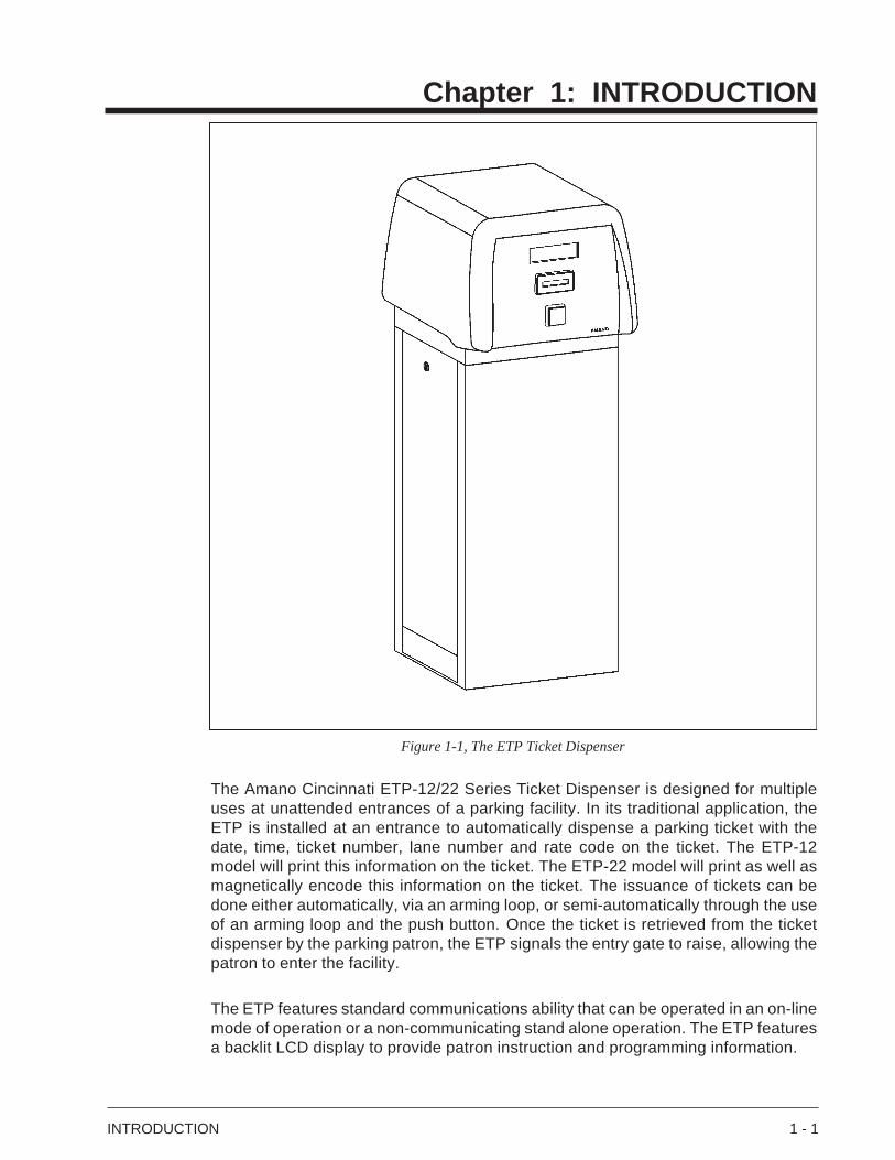
Figure 1-1, The ETP Ticket Dispenser
The Amano Cincinnati ETP-12/22 Series Ticket Dispenser is designed for multipleuses at unattended entrances of a parking facility. In its traditional application, theETP is installed at an entrance to automatically dispense a parking ticket with thedate, time, ticket number, lane number and rate code on the ticket. The ETP-12model will print this information on the ticket. The ETP-22 model will print as well asmagnetically encode this information on the ticket. The issuance of tickets can bedone either automatically, via an arming loop, or semi-automatically through the useof an arming loop and the push button. Once the ticket is retrieved from the ticketdispenser by the parking patron, the ETP signals the entry gate to raise, allowing thepatron to enter the facility.
The ETP features standard communications ability that can be operated in an on-linemode of operation or a non-communicating stand alone operation. The ETP featuresa backlit LCD display to provide patron instruction and programming information.
Chapter 1: INTRODUCTION

1 - 2 INTRODUCTION
SPECIFICATIONS 2 - 1
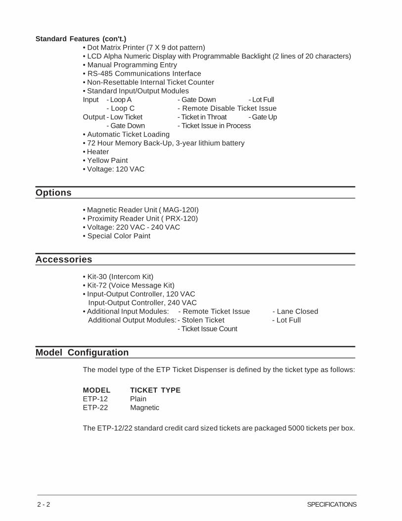
Figure 2-2, Example of Standard Printed Ticket
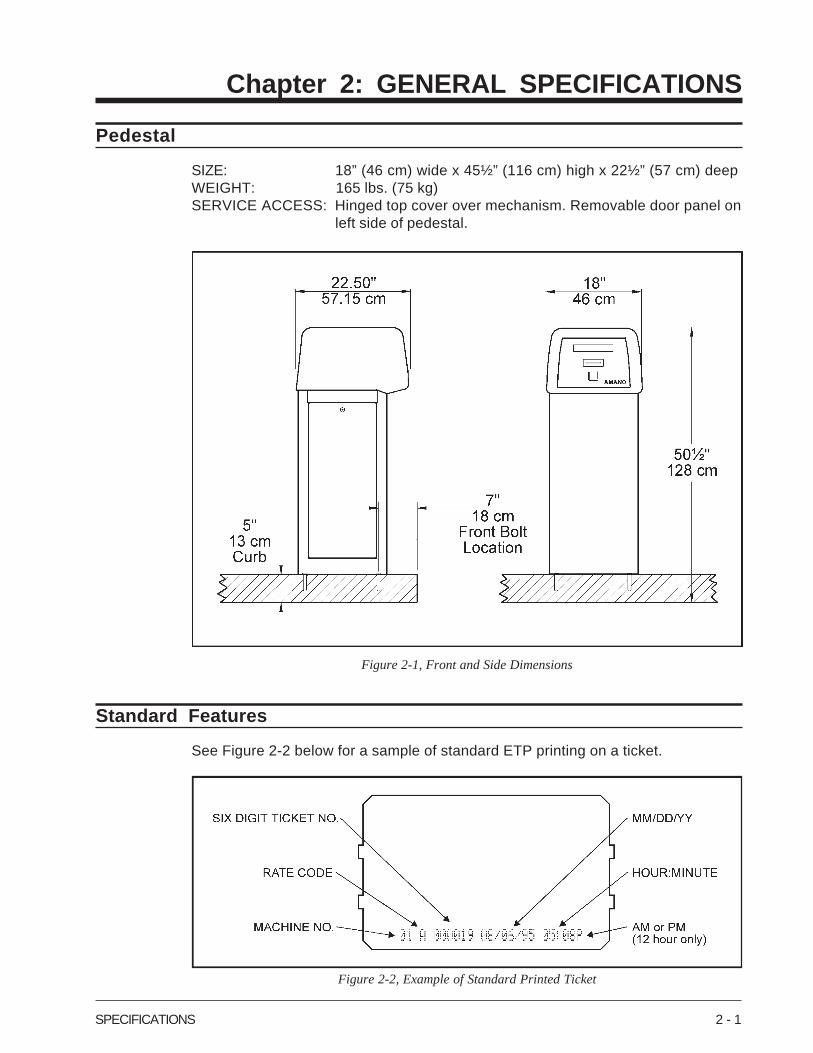
Figure 2-1, Front and Side Dimensions
Chapter 2: GENERAL SPECIFICATIONS
Pedestal
SIZE: 18” (46 cm) wide x 45½” (116 cm) high x 22½” (57 cm) deepWEIGHT: 165 lbs. (75 kg)SERVICE ACCESS: Hinged top cover over mechanism. Removable door panel on
left side of pedestal.
Standard Features
See Figure 2-2 below for a sample of standard ETP printing on a ticket.
2 - 2 SPECIFICATIONS
Standard Features (con't.)• Dot Matrix Printer (7 X 9 dot pattern)• LCD Alpha Numeric Display with Programmable Backlight (2 lines of 20 characters)• Manual Programming Entry• RS-485 Communications Interface• Non-Resettable Internal Ticket Counter• Standard Input/Output ModulesInput - Loop A - Gate Down - Lot Full
- Loop C - Remote Disable Ticket IssueOutput - Low Ticket - Ticket in Throat - Gate Up
- Gate Down - Ticket Issue in Process• Automatic Ticket Loading• 72 Hour Memory Back-Up, 3-year lithium battery• Heater• Yellow Paint• Voltage: 120 VAC
Options
• Magnetic Reader Unit ( MAG-120I)• Proximity Reader Unit ( PRX-120)• Voltage: 220 VAC - 240 VAC• Special Color Paint
Accessories
• Kit-30 (Intercom Kit)• Kit-72 (Voice Message Kit)• Input-Output Controller, 120 VAC Input-Output Controller, 240 VAC• Additional Input Modules: - Remote Ticket Issue - Lane Closed Additional Output Modules: - Stolen Ticket - Lot Full
- Ticket Issue Count
Model Configuration
The model type of the ETP Ticket Dispenser is defined by the ticket type as follows:
MODEL TICKET TYPEETP-12 PlainETP-22 Magnetic
The ETP-12/22 standard credit card sized tickets are packaged 5000 tickets per box.
SPECIFICATIONS 2 - 3
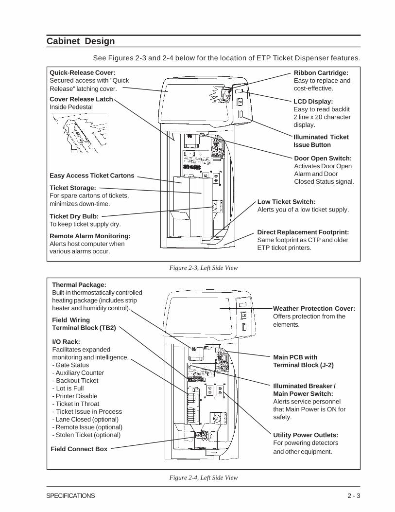
Quick-Release Cover:Secured access with "QuickRelease" latching cover.
Ribbon Cartridge:Easy to replace andcost-effective.
Remote Alarm Monitoring:Alerts host computer whenvarious alarms occur.
Figure 2-3, Left Side View
Figure 2-4, Left Side View
Thermal Package:Built-in thermostatically controlledheating package (includes stripheater and humidity control).
Field WiringTerminal Block (TB2)
LCD Display:Easy to read backlit2 line x 20 characterdisplay.
Illuminated TicketIssue Button
Door Open Switch:Activates Door OpenAlarm and DoorClosed Status signal.
Direct Replacement Footprint:Same footprint as CTP and olderETP ticket printers.
Low Ticket Switch:Alerts you of a low ticket supply.
Ticket Dry Bulb:To keep ticket supply dry.
Ticket Storage:For spare cartons of tickets,minimizes down-time.
Easy Access Ticket Cartons
Cover Release LatchInside Pedestal
Field Connect Box
I/O Rack:Facilitates expandedmonitoring and intelligence.- Gate Status- Auxiliary Counter- Backout Ticket- Lot is Full- Printer Disable- Ticket in Throat- Ticket Issue in Process- Lane Closed (optional)- Remote Issue (optional)- Stolen Ticket (optional)
Main PCB withTerminal Block (J-2)
Illuminated Breaker /Main Power Switch:Alerts service personnelthat Main Power is ON forsafety.
Utility Power Outlets:For powering detectorsand other equipment.
Weather Protection Cover:Offers protection from theelements.
Cabinet Design
See Figures 2-3 and 2-4 below for the location of ETP Ticket Dispenser features.

2 - 4 SPECIFICATIONS
INSTALLATION 3 - 1
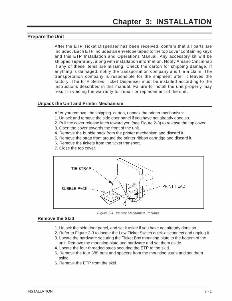
Figure 3-1, Printer Mechanism Packing
Chapter 3: INSTALLATION
Prepare the Unit
After the ETP Ticket Dispenser has been received, confirm that all parts areincluded. Each ETP includes an envelope taped to the top cover containing keysand this ETP Installation and Operations Manual. Any accessory kit will beshipped separately, along with installation information. Notify Amano Cincinnatiif any of these items are missing. Check the carton for shipping damage. Ifanything is damaged, notify the transportation company and file a claim. Thetransportation company is responsible for the shipment after it leaves thefactory. The ETP Series Ticket Dispenser must be installed according to theinstructions described in this manual. Failure to install the unit properly mayresult in voiding the warranty for repair or replacement of the unit.
Unpack the Unit and Printer Mechanism
After you remove the shipping carton, unpack the printer mechanism:1. Unlock and remove the side door panel if you have not already done so.2. Pull the cover release latch toward you (see Figure 2-3) to release the top cover.3. Open the cover towards the front of the unit.4. Remove the bubble pack from the printer mechanism and discard it.5. Remove the strap from around the printer ribbon cartridge and discard it.6. Remove the tickets from the ticket transport.7. Close the top cover.
Remove the Skid
1. Unlock the side door panel, and set it aside if you have not already done so.2. Refer to Figure 2-3 to locate the Low Ticket Switch quick-disconnect and unplug it.3. Locate the hardware securing the Ticket Box mounting plate to the bottom of the
unit. Remove the mounting plate and hardware and set them aside.4. Locate the four threaded studs securing the ETP to the skid.5. Remove the four 3/8” nuts and spacers from the mounting studs and set them
aside.6. Remove the ETP from the skid.
3 - 2 INSTALLATION
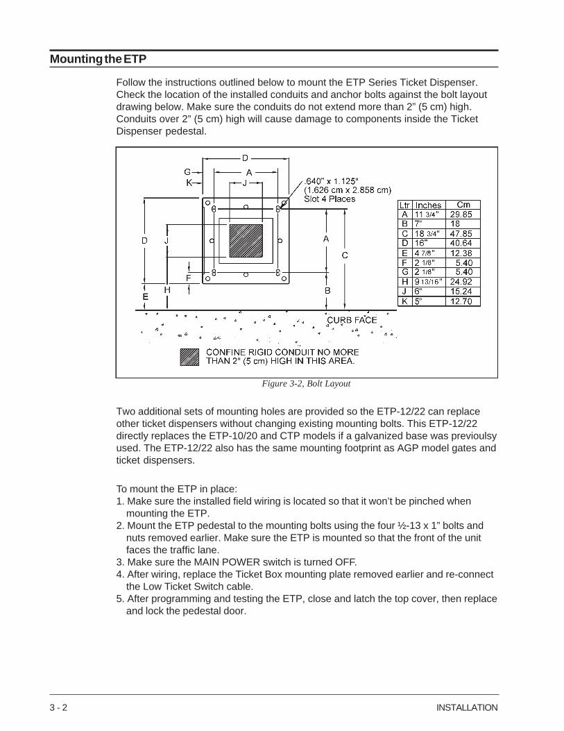
Figure 3-2, Bolt Layout
Mounting the ETP
Follow the instructions outlined below to mount the ETP Series Ticket Dispenser.Check the location of the installed conduits and anchor bolts against the bolt layoutdrawing below. Make sure the conduits do not extend more than 2” (5 cm) high.Conduits over 2” (5 cm) high will cause damage to components inside the TicketDispenser pedestal.
Two additional sets of mounting holes are provided so the ETP-12/22 can replaceother ticket dispensers without changing existing mounting bolts. This ETP-12/22directly replaces the ETP-10/20 and CTP models if a galvanized base was previoulsyused. The ETP-12/22 also has the same mounting footprint as AGP model gates andticket dispensers.
To mount the ETP in place:1. Make sure the installed field wiring is located so that it won’t be pinched when
mounting the ETP.2. Mount the ETP pedestal to the mounting bolts using the four ½-13 x 1” bolts and
nuts removed earlier. Make sure the ETP is mounted so that the front of the unitfaces the traffic lane.
3. Make sure the MAIN POWER switch is turned OFF.4. After wiring, replace the Ticket Box mounting plate removed earlier and re-connect
the Low Ticket Switch cable.5. After programming and testing the ETP, close and latch the top cover, then replace
and lock the pedestal door.
INSTALLATION 3 - 3
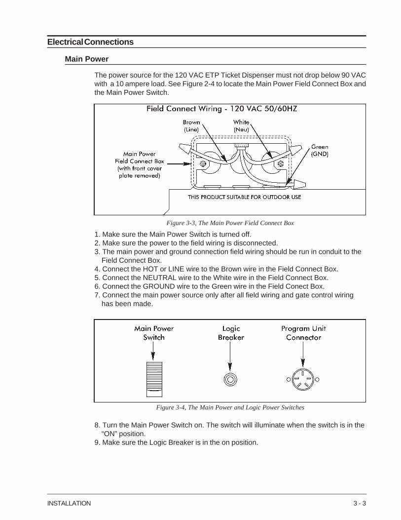
Figure 3-3, The Main Power Field Connect Box
Figure 3-4, The Main Power and Logic Power Switches
Electrical Connections
Main Power
The power source for the 120 VAC ETP Ticket Dispenser must not drop below 90 VACwith a 10 ampere load. See Figure 2-4 to locate the Main Power Field Connect Box andthe Main Power Switch.
1. Make sure the Main Power Switch is turned off.2. Make sure the power to the field wiring is disconnected.3. The main power and ground connection field wiring should be run in conduit to the
Field Connect Box.4. Connect the HOT or LINE wire to the Brown wire in the Field Connect Box.5. Connect the NEUTRAL wire to the White wire in the Field Connect Box.6. Connect the GROUND wire to the Green wire in the Field Conect Box.7. Connect the main power source only after all field wiring and gate control wiring
has been made.
8. Turn the Main Power Switch on. The switch will illuminate when the switch is in the“ON” position.
9. Make sure the Logic Breaker is in the on position.
3 - 4 INSTALLATION
Terminal Block Connections
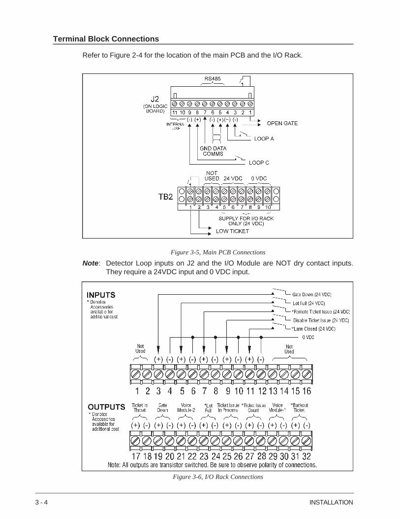
Refer to Figure 2-4 for the location of the main PCB and the I/O Rack.
Figure 3-6, I/O Rack Connections
Figure 3-5, Main PCB Connections
Note: Detector Loop inputs on J2 and the I/O Module are NOT dry contact inputs.They require a 24VDC input and 0 VDC input.
INSTALLATION 3 - 5
Gate Control Boards
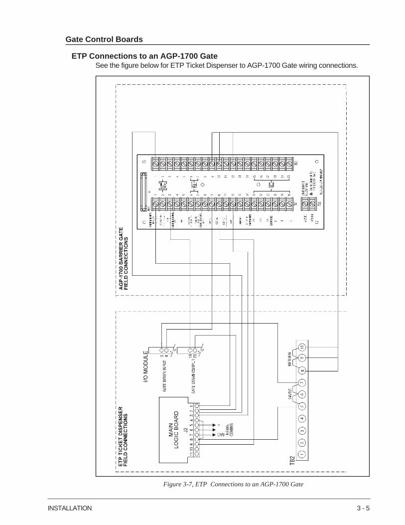
ETP Connections to an AGP-1700 GateSee the figure below for ETP Ticket Dispenser to AGP-1700 Gate wiring connections.
Figure 3-7, ETP Connections to an AGP-1700 Gate
3 - 6 INSTALLATION
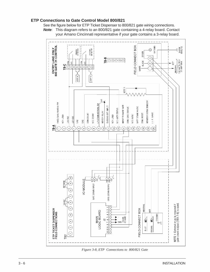
Figure 3-8, ETP Connections to 800/821 Gate
ETP Connections to Gate Control Model 800/821See the figure below for ETP Ticket Dispenser to 800/821 gate wiring connections.Note: This diagram refers to an 800/821 gate containing a 4-relay board. Contact
your Amano Cincinnati representative if your gate contains a 3-relay board.
INSTALLATION 3 - 7
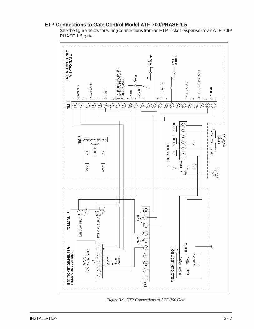
Figure 3-9, ETP Connections to ATF-700 Gate
ETP Connections to Gate Control Model ATF-700/PHASE 1.5See the figure below for wiring connections from an ETP Ticket Dispenser to an ATF-700/PHASE 1.5 gate.
3 - 8 INSTALLATION
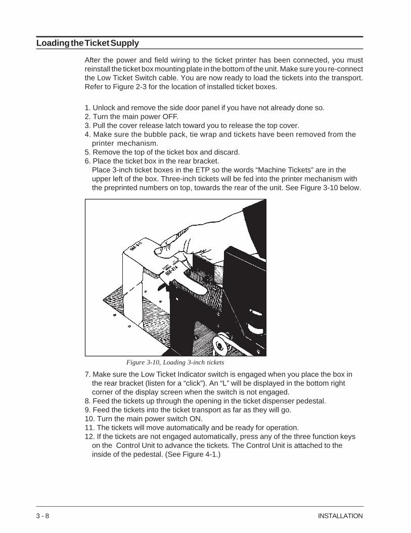
Figure 3-10, Loading 3-inch tickets
Loading the Ticket Supply
After the power and field wiring to the ticket printer has been connected, you mustreinstall the ticket box mounting plate in the bottom of the unit. Make sure you re-connectthe Low Ticket Switch cable. You are now ready to load the tickets into the transport.Refer to Figure 2-3 for the location of installed ticket boxes.
1. Unlock and remove the side door panel if you have not already done so.2. Turn the main power OFF.3. Pull the cover release latch toward you to release the top cover.4. Make sure the bubble pack, tie wrap and tickets have been removed from the
printer mechanism.5. Remove the top of the ticket box and discard.6. Place the ticket box in the rear bracket.
Place 3-inch ticket boxes in the ETP so the words “Machine Tickets” are in theupper left of the box. Three-inch tickets will be fed into the printer mechanism withthe preprinted numbers on top, towards the rear of the unit. See Figure 3-10 below.
7. Make sure the Low Ticket Indicator switch is engaged when you place the box inthe rear bracket (listen for a “click”). An “L” will be displayed in the bottom rightcorner of the display screen when the switch is not engaged.
8. Feed the tickets up through the opening in the ticket dispenser pedestal.9. Feed the tickets into the ticket transport as far as they will go.10. Turn the main power switch ON.11. The tickets will move automatically and be ready for operation.12. If the tickets are not engaged automatically, press any of the three function keys
on the Control Unit to advance the tickets. The Control Unit is attached to theinside of the pedestal. (See Figure 4-1.)
PROGRAMMING THE ETP 4 - 1
STEP NO. PROGRAMMED DATA DESCRIPTION ACCEPTABLE DATA (DEFAULT DATA)
O1 LOT NO. O1 - 99 (4O)
O2 MACHINE NO. O1 - 99 (O1)
O3 DATE MM/DD/YY MONTH O1 - 12 DATE O1 - 31 YEAR OO - 99 (O/O/8O)
O4 TIME 00:00 12H/24H HOUR 00-23 MIN 00-59 (00:00)
O5 RATE A-H (A)
O6 TIMER - 1 OO - 99 SECONDS (1O)
O7 TIMER - 2 OO - 99 SECONDS (1O)
O8 TICKET NO. OOOOOO-999999 (OOOOOO)
O9 PRINT RATE NO/YES (YES)
1O TICKET ISSUE BUTTON/LOOP/BOTH (BUTTON)
11 USE GATE NO/YES (NO)
12 ISSUE FULL NO/YES (NO)
13 AFTER FULL NO/YES (NO)
14 CHECK EXIT LOOP NO/YES (NO)
15 EXIT LOOP NO/YES (NO)
16 BEEP NO/YES (YES)
17 TIME BASE 60 CYCLES 50 CYCLES INTERNAL (50)
18 NEW PASS OOOO - 9999 (OOOO)
19 COUNTER OOOOOOOOOO - 9999999999 (OOOOOOOOOO)
2O LIGHT MODE MANUAL/TIME/LOOP (MANUAL)
21 BACK LIGHT NO/YES (NO)
22 LIGHT ON TIME HOUR OO-23 MIN OO-59 (OO:OO)
23 LIGHT OFF TIME HOUR OO-23 MIN OO-59 (23:59)
24 PRINT NUMBER NO/YES (YES)
25 NO. OF TICKETS O1 - 1O (O1)
26 CUSTOM MESSAGE 2O DIGIT ALPHANUMERIC DATA (AMANO CINCINNATI)
27 DATA FORMAT TF-259O/CTP-7 (TF-259O)
28 VOICE PUSH BUTTON/TAKE TICKET(TAKE TICKET)
29 TICKET SIZE 3 INCH/5 INCH (3 INCH)
30 US DATE NO/YES (YES)
31 IN PROCESS NO/YES (YES)
Chapter 4: PROGRAMMING THE ETP
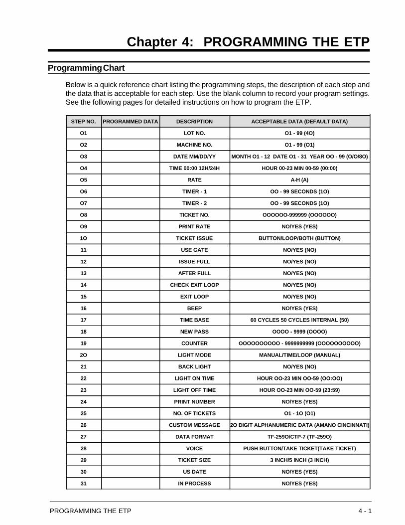
Programming Chart
Below is a quick reference chart listing the programming steps, the description of each step andthe data that is acceptable for each step. Use the blank column to record your program settings.See the following pages for detailed instructions on how to program the ETP.
4 - 2 PROGRAMMING THE ETP
Figure 4-1, The Control Unit
Initiate the Program Mode
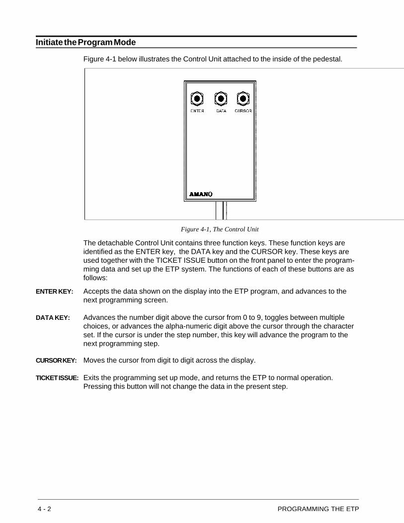
Figure 4-1 below illustrates the Control Unit attached to the inside of the pedestal.
The detachable Control Unit contains three function keys. These function keys areidentified as the ENTER key, the DATA key and the CURSOR key. These keys areused together with the TICKET ISSUE button on the front panel to enter the program-ming data and set up the ETP system. The functions of each of these buttons are asfollows:
ENTER KEY: Accepts the data shown on the display into the ETP program, and advances to thenext programming screen.
DATA KEY: Advances the number digit above the cursor from 0 to 9, toggles between multiplechoices, or advances the alpha-numeric digit above the cursor through the characterset. If the cursor is under the step number, this key will advance the program to thenext programming step.
CURSOR KEY: Moves the cursor from digit to digit across the display.
TICKET ISSUE: Exits the programming set up mode, and returns the ETP to normal operation.Pressing this button will not change the data in the present step.
PROGRAMMING THE ETP 4 - 3
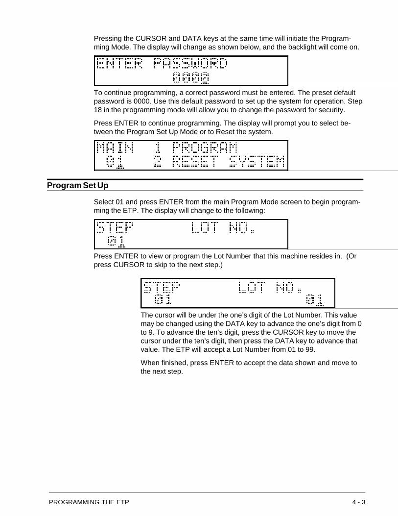
Pressing the CURSOR and DATA keys at the same time will initiate the Program-ming Mode. The display will change as shown below, and the backlight will come on.
To continue programming, a correct password must be entered. The preset defaultpassword is 0000. Use this default password to set up the system for operation. Step18 in the programming mode will allow you to change the password for security.
Press ENTER to continue programming. The display will prompt you to select be-tween the Program Set Up Mode or to Reset the system.
Program Set Up
Select 01 and press ENTER from the main Program Mode screen to begin program-ming the ETP. The display will change to the following:
Press ENTER to view or program the Lot Number that this machine resides in. (Orpress CURSOR to skip to the next step.)
The cursor will be under the one’s digit of the Lot Number. This valuemay be changed using the DATA key to advance the one’s digit from 0to 9. To advance the ten’s digit, press the CURSOR key to move thecursor under the ten’s digit, then press the DATA key to advance thatvalue. The ETP will accept a Lot Number from 01 to 99.
When finished, press ENTER to accept the data shown and move tothe next step.
4 - 4 PROGRAMMING THE ETP
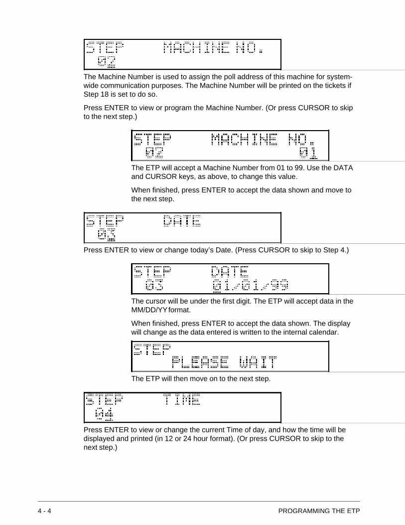
The Machine Number is used to assign the poll address of this machine for system-wide communication purposes. The Machine Number will be printed on the tickets ifStep 18 is set to do so.
Press ENTER to view or program the Machine Number. (Or press CURSOR to skipto the next step.)
The ETP will accept a Machine Number from 01 to 99. Use the DATAand CURSOR keys, as above, to change this value.
When finished, press ENTER to accept the data shown and move tothe next step.
Press ENTER to view or change today’s Date. (Press CURSOR to skip to Step 4.)
The cursor will be under the first digit. The ETP will accept data in theMM/DD/YY format.
When finished, press ENTER to accept the data shown. The displaywill change as the data entered is written to the internal calendar.
The ETP will then move on to the next step.
Press ENTER to view or change the current Time of day, and how the time will bedisplayed and printed (in 12 or 24 hour format). (Or press CURSOR to skip to thenext step.)
PROGRAMMING THE ETP 4 - 5
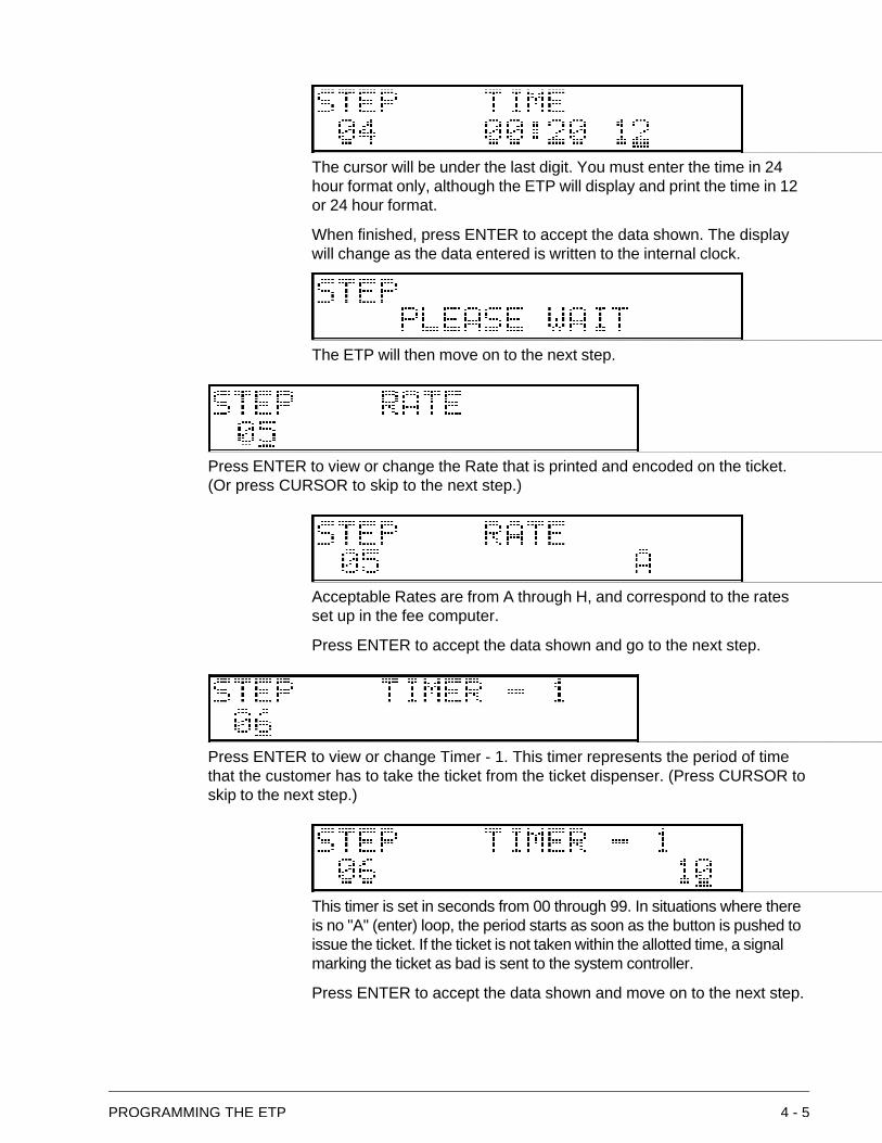
The cursor will be under the last digit. You must enter the time in 24hour format only, although the ETP will display and print the time in 12or 24 hour format.
When finished, press ENTER to accept the data shown. The displaywill change as the data entered is written to the internal clock.
The ETP will then move on to the next step.
Press ENTER to view or change the Rate that is printed and encoded on the ticket.(Or press CURSOR to skip to the next step.)
Acceptable Rates are from A through H, and correspond to the ratesset up in the fee computer.
Press ENTER to accept the data shown and go to the next step.
Press ENTER to view or change Timer - 1. This timer represents the period of timethat the customer has to take the ticket from the ticket dispenser. (Press CURSOR toskip to the next step.)
This timer is set in seconds from 00 through 99. In situations where thereis no "A" (enter) loop, the period starts as soon as the button is pushed toissue the ticket. If the ticket is not taken within the allotted time, a signalmarking the ticket as bad is sent to the system controller.
Press ENTER to accept the data shown and move on to the next step.
4 - 6 PROGRAMMING THE ETP
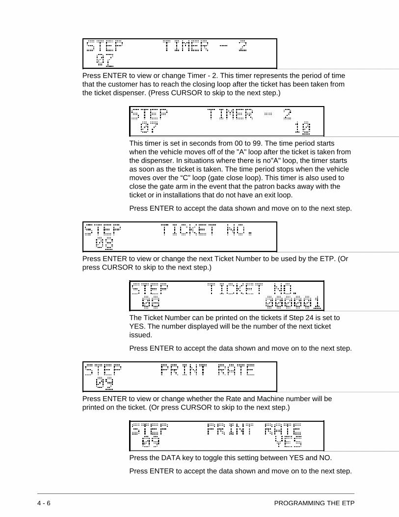
Press ENTER to view or change Timer - 2. This timer represents the period of timethat the customer has to reach the closing loop after the ticket has been taken fromthe ticket dispenser. (Press CURSOR to skip to the next step.)
This timer is set in seconds from 00 to 99. The time period startswhen the vehicle moves off of the "A" loop after the ticket is taken fromthe dispenser. In situations where there is no"A" loop, the timer startsas soon as the ticket is taken. The time period stops when the vehiclemoves over the “C” loop (gate close loop). This timer is also used toclose the gate arm in the event that the patron backs away with theticket or in installations that do not have an exit loop.
Press ENTER to accept the data shown and move on to the next step.
Press ENTER to view or change the next Ticket Number to be used by the ETP. (Orpress CURSOR to skip to the next step.)
The Ticket Number can be printed on the tickets if Step 24 is set toYES. The number displayed will be the number of the next ticketissued.
Press ENTER to accept the data shown and move on to the next step.
Press ENTER to view or change whether the Rate and Machine number will beprinted on the ticket. (Or press CURSOR to skip to the next step.)
Press the DATA key to toggle this setting between YES and NO.
Press ENTER to accept the data shown and move on to the next step.
PROGRAMMING THE ETP 4 - 7
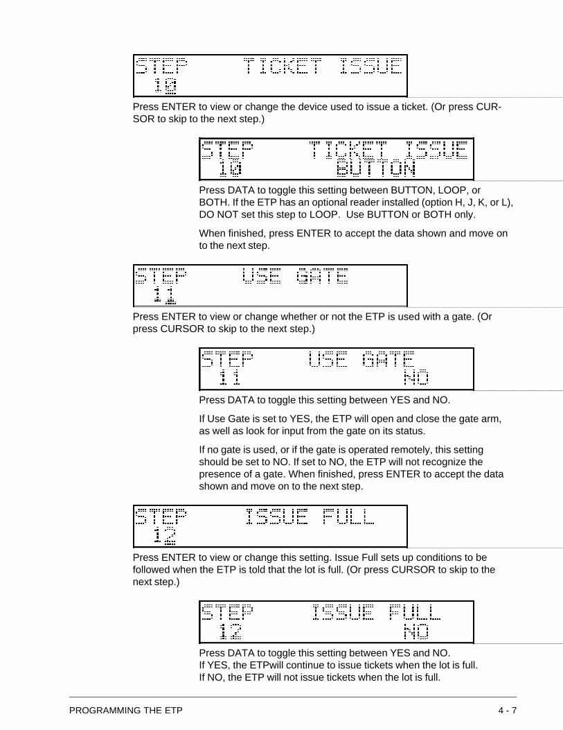
Press ENTER to view or change the device used to issue a ticket. (Or press CUR-SOR to skip to the next step.)
Press DATA to toggle this setting between BUTTON, LOOP, orBOTH. If the ETP has an optional reader installed (option H, J, K, or L),DO NOT set this step to LOOP. Use BUTTON or BOTH only.
When finished, press ENTER to accept the data shown and move onto the next step.
Press ENTER to view or change whether or not the ETP is used with a gate. (Orpress CURSOR to skip to the next step.)
Press DATA to toggle this setting between YES and NO.
If Use Gate is set to YES, the ETP will open and close the gate arm,as well as look for input from the gate on its status.
If no gate is used, or if the gate is operated remotely, this settingshould be set to NO. If set to NO, the ETP will not recognize thepresence of a gate. When finished, press ENTER to accept the datashown and move on to the next step.
Press ENTER to view or change this setting. Issue Full sets up conditions to befollowed when the ETP is told that the lot is full. (Or press CURSOR to skip to thenext step.)
Press DATA to toggle this setting between YES and NO.If YES, the ETPwill continue to issue tickets when the lot is full.If NO, the ETP will not issue tickets when the lot is full.
4 - 8 PROGRAMMING THE ETP
When finished, press ENTER to accept the data shown and move onto the next step.
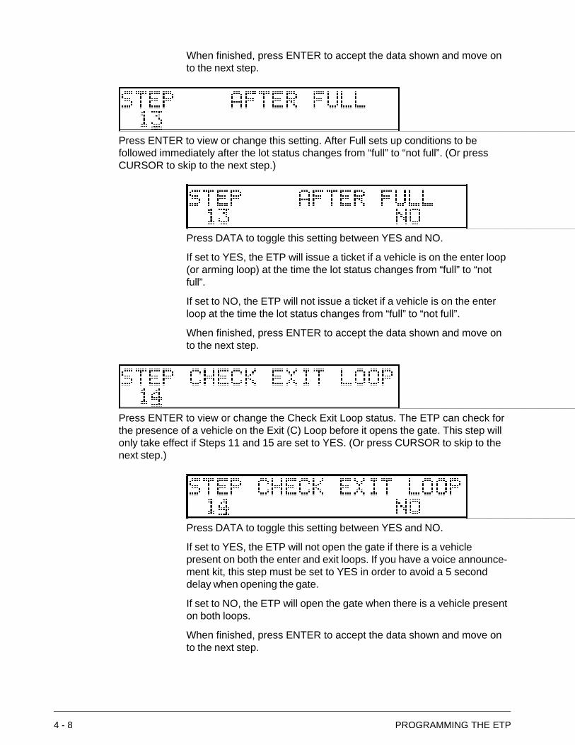
Press ENTER to view or change this setting. After Full sets up conditions to befollowed immediately after the lot status changes from “full” to “not full”. (Or pressCURSOR to skip to the next step.)
Press DATA to toggle this setting between YES and NO.
If set to YES, the ETP will issue a ticket if a vehicle is on the enter loop(or arming loop) at the time the lot status changes from “full” to “notfull”.
If set to NO, the ETP will not issue a ticket if a vehicle is on the enterloop at the time the lot status changes from “full” to “not full”.
When finished, press ENTER to accept the data shown and move onto the next step.
Press ENTER to view or change the Check Exit Loop status. The ETP can check forthe presence of a vehicle on the Exit (C) Loop before it opens the gate. This step willonly take effect if Steps 11 and 15 are set to YES. (Or press CURSOR to skip to thenext step.)
Press DATA to toggle this setting between YES and NO.
If set to YES, the ETP will not open the gate if there is a vehiclepresent on both the enter and exit loops. If you have a voice announce-ment kit, this step must be set to YES in order to avoid a 5 seconddelay when opening the gate.
If set to NO, the ETP will open the gate when there is a vehicle presenton both loops.
When finished, press ENTER to accept the data shown and move onto the next step.
PROGRAMMING THE ETP 4 - 9
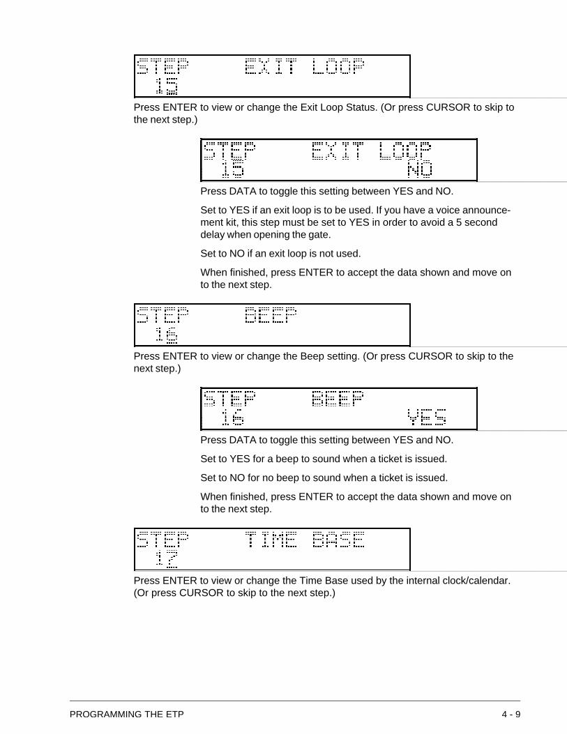
Press ENTER to view or change the Exit Loop Status. (Or press CURSOR to skip tothe next step.)
Press DATA to toggle this setting between YES and NO.
Set to YES if an exit loop is to be used. If you have a voice announce-ment kit, this step must be set to YES in order to avoid a 5 seconddelay when opening the gate.
Set to NO if an exit loop is not used.
When finished, press ENTER to accept the data shown and move onto the next step.
Press ENTER to view or change the Beep setting. (Or press CURSOR to skip to thenext step.)
Press DATA to toggle this setting between YES and NO.
Set to YES for a beep to sound when a ticket is issued.
Set to NO for no beep to sound when a ticket is issued.
When finished, press ENTER to accept the data shown and move onto the next step.
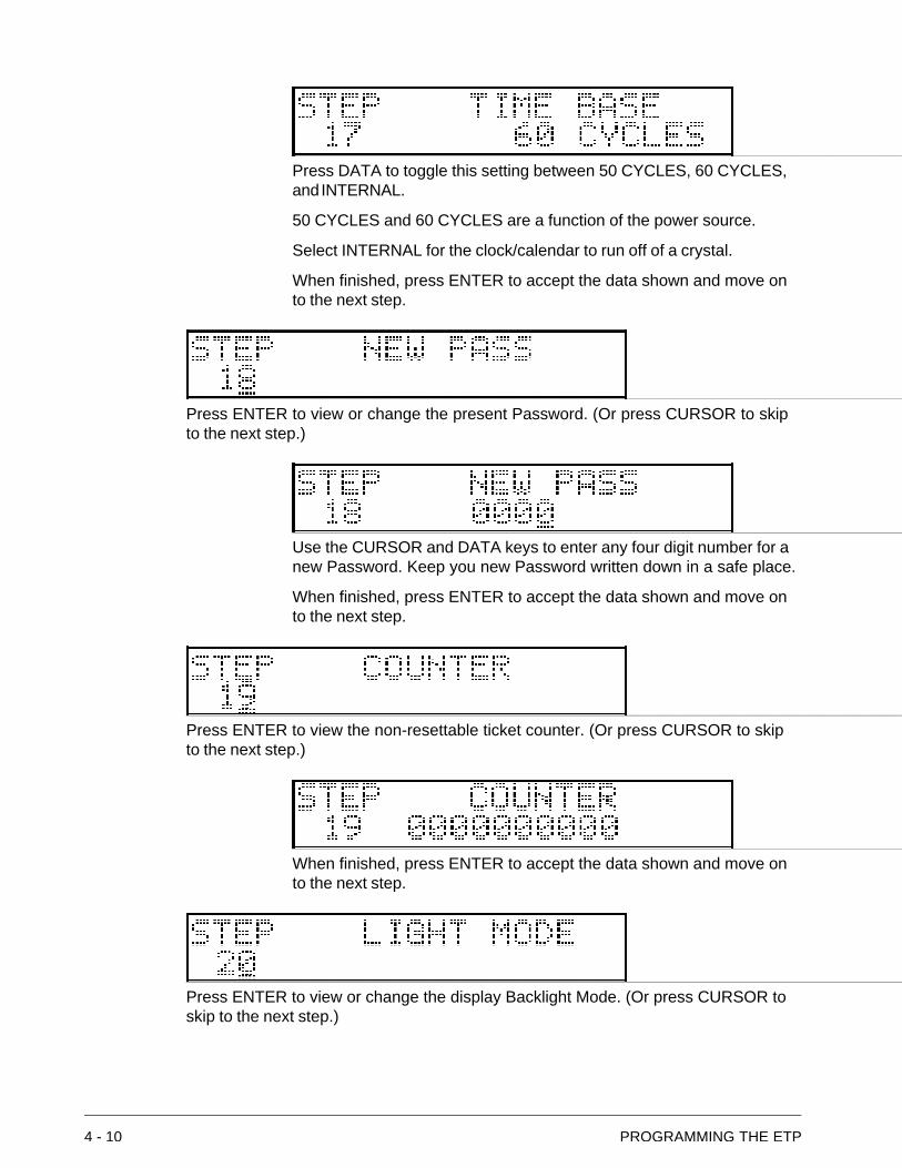
Press ENTER to view or change the Time Base used by the internal clock/calendar.(Or press CURSOR to skip to the next step.)
4 - 10 PROGRAMMING THE ETP
Press DATA to toggle this setting between 50 CYCLES, 60 CYCLES,and INTERNAL.
50 CYCLES and 60 CYCLES are a function of the power source.
Select INTERNAL for the clock/calendar to run off of a crystal.
When finished, press ENTER to accept the data shown and move onto the next step.
Press ENTER to view or change the present Password. (Or press CURSOR to skipto the next step.)
Use the CURSOR and DATA keys to enter any four digit number for anew Password. Keep you new Password written down in a safe place.
When finished, press ENTER to accept the data shown and move onto the next step.
Press ENTER to view the non-resettable ticket counter. (Or press CURSOR to skipto the next step.)
When finished, press ENTER to accept the data shown and move onto the next step.
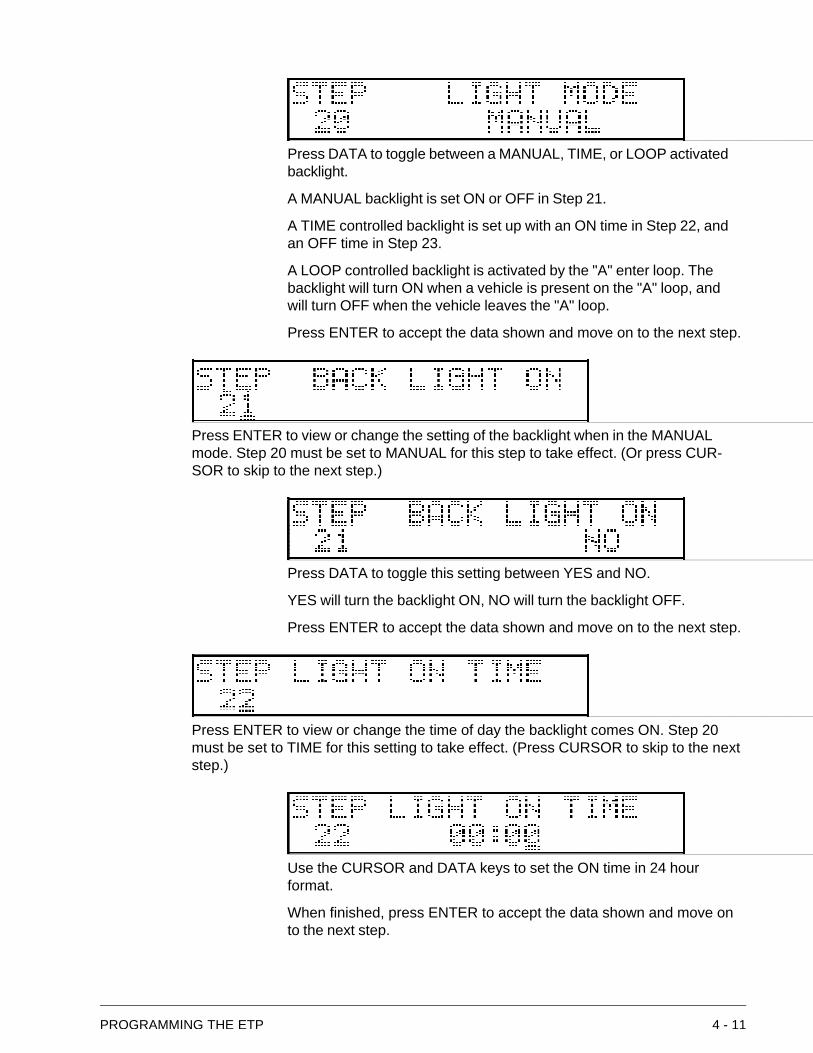
Press ENTER to view or change the display Backlight Mode. (Or press CURSOR toskip to the next step.)
PROGRAMMING THE ETP 4 - 11
Press DATA to toggle between a MANUAL, TIME, or LOOP activatedbacklight.
A MANUAL backlight is set ON or OFF in Step 21.
A TIME controlled backlight is set up with an ON time in Step 22, andan OFF time in Step 23.
A LOOP controlled backlight is activated by the "A" enter loop. Thebacklight will turn ON when a vehicle is present on the "A" loop, andwill turn OFF when the vehicle leaves the "A" loop.
Press ENTER to accept the data shown and move on to the next step.
Press ENTER to view or change the setting of the backlight when in the MANUALmode. Step 20 must be set to MANUAL for this step to take effect. (Or press CUR-SOR to skip to the next step.)
Press DATA to toggle this setting between YES and NO.
YES will turn the backlight ON, NO will turn the backlight OFF.
Press ENTER to accept the data shown and move on to the next step.
Press ENTER to view or change the time of day the backlight comes ON. Step 20must be set to TIME for this setting to take effect. (Press CURSOR to skip to the nextstep.)
Use the CURSOR and DATA keys to set the ON time in 24 hourformat.
When finished, press ENTER to accept the data shown and move onto the next step.
4 - 12 PROGRAMMING THE ETP
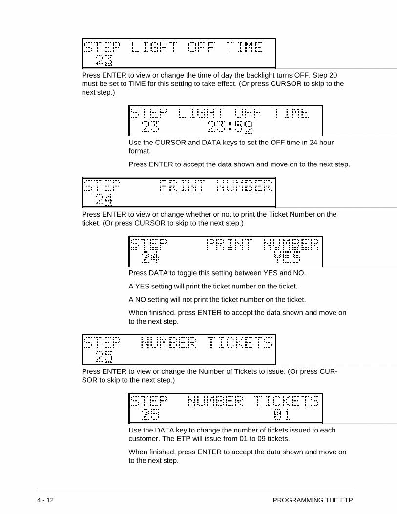
Press ENTER to view or change the time of day the backlight turns OFF. Step 20must be set to TIME for this setting to take effect. (Or press CURSOR to skip to thenext step.)
Use the CURSOR and DATA keys to set the OFF time in 24 hourformat.
Press ENTER to accept the data shown and move on to the next step.
Press ENTER to view or change whether or not to print the Ticket Number on theticket. (Or press CURSOR to skip to the next step.)
Press DATA to toggle this setting between YES and NO.
A YES setting will print the ticket number on the ticket.
A NO setting will not print the ticket number on the ticket.
When finished, press ENTER to accept the data shown and move onto the next step.
Press ENTER to view or change the Number of Tickets to issue. (Or press CUR-SOR to skip to the next step.)
Use the DATA key to change the number of tickets issued to eachcustomer. The ETP will issue from 01 to 09 tickets.
When finished, press ENTER to accept the data shown and move onto the next step.
PROGRAMMING THE ETP 4 - 13
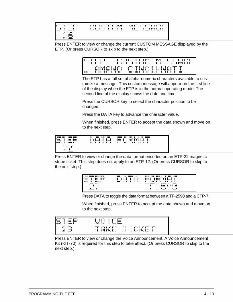
Press ENTER to view or change the current CUSTOM MESSAGE displayed by theETP. (Or press CURSOR to skip to the next step.)
The ETP has a full set of alpha-numeric characters available to cus-tomize a message. This custom message will appear on the first lineof the display when the ETP is in the normal operating mode. Thesecond line of the display shows the date and time.
Press the CURSOR key to select the character position to bechanged.
Press the DATA key to advance the character value.
When finished, press ENTER to accept the data shown and move onto the next step.
Press ENTER to view or change the data format encoded on an ETP-22 magneticstripe ticket. This step does not apply to an ETP-12. (Or press CURSOR to skip tothe next step.)
Press DATA to toggle the data format between a TF-2590 and a CTP-7.
When finished, press ENTER to accept the data shown and move onto the next step.
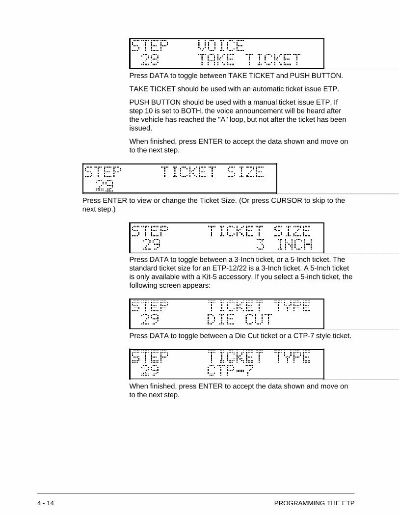
Press ENTER to view or change the Voice Announcement. A Voice AnnouncementKit (KIT-70) is required for this step to take effect. (Or press CURSOR to skip to thenext step.)
4 - 14 PROGRAMMING THE ETP
Press DATA to toggle between TAKE TICKET and PUSH BUTTON.
TAKE TICKET should be used with an automatic ticket issue ETP.
PUSH BUTTON should be used with a manual ticket issue ETP. Ifstep 10 is set to BOTH, the voice announcement will be heard afterthe vehicle has reached the "A" loop, but not after the ticket has beenissued.
When finished, press ENTER to accept the data shown and move onto the next step.
Press ENTER to view or change the Ticket Size. (Or press CURSOR to skip to thenext step.)
Press DATA to toggle between a 3-Inch ticket, or a 5-Inch ticket. Thestandard ticket size for an ETP-12/22 is a 3-Inch ticket. A 5-Inch ticketis only available with a Kit-5 accessory. If you select a 5-inch ticket, thefollowing screen appears:
Press DATA to toggle between a Die Cut ticket or a CTP-7 style ticket.
When finished, press ENTER to accept the data shown and move onto the next step.
PROGRAMMING THE ETP 4 - 15
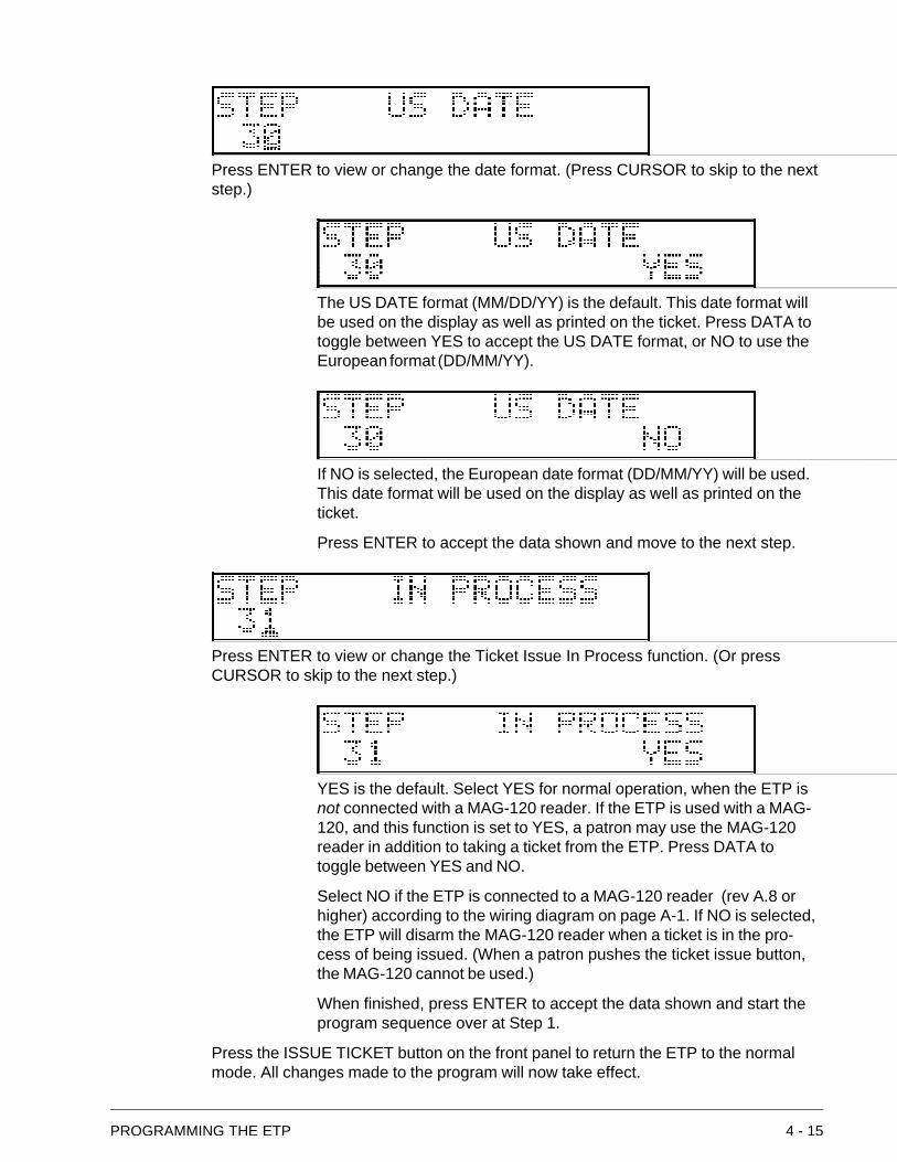
Press ENTER to view or change the date format. (Press CURSOR to skip to the nextstep.)
The US DATE format (MM/DD/YY) is the default. This date format willbe used on the display as well as printed on the ticket. Press DATA totoggle between YES to accept the US DATE format, or NO to use theEuropean format (DD/MM/YY).
If NO is selected, the European date format (DD/MM/YY) will be used.This date format will be used on the display as well as printed on theticket.
Press ENTER to accept the data shown and move to the next step.
Press ENTER to view or change the Ticket Issue In Process function. (Or pressCURSOR to skip to the next step.)
YES is the default. Select YES for normal operation, when the ETP isnot connected with a MAG-120 reader. If the ETP is used with a MAG-120, and this function is set to YES, a patron may use the MAG-120reader in addition to taking a ticket from the ETP. Press DATA totoggle between YES and NO.
Select NO if the ETP is connected to a MAG-120 reader (rev A.8 orhigher) according to the wiring diagram on page A-1. If NO is selected,the ETP will disarm the MAG-120 reader when a ticket is in the pro-cess of being issued. (When a patron pushes the ticket issue button,the MAG-120 cannot be used.)
When finished, press ENTER to accept the data shown and start theprogram sequence over at Step 1.
Press the ISSUE TICKET button on the front panel to return the ETP to the normalmode. All changes made to the program will now take effect.
4 - 16 PROGRAMMING THE ETP
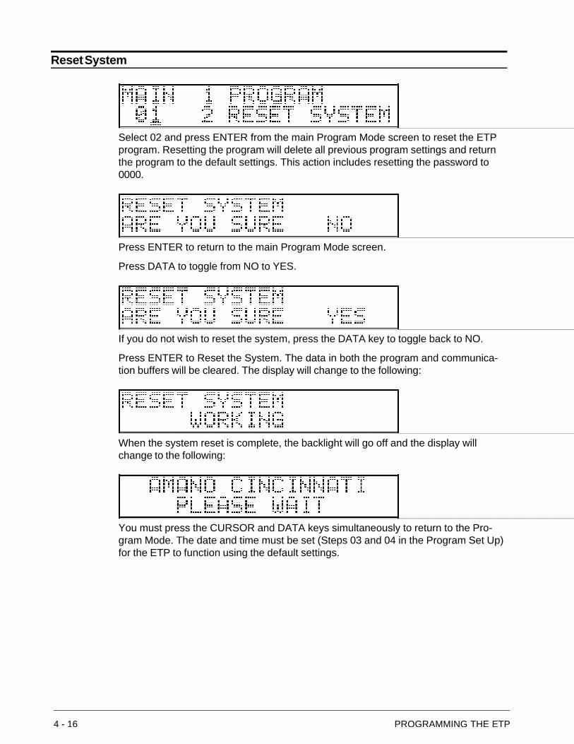
Reset System
Select 02 and press ENTER from the main Program Mode screen to reset the ETPprogram. Resetting the program will delete all previous program settings and returnthe program to the default settings. This action includes resetting the password to0000.
Press ENTER to return to the main Program Mode screen.
Press DATA to toggle from NO to YES.
If you do not wish to reset the system, press the DATA key to toggle back to NO.
Press ENTER to Reset the System. The data in both the program and communica-tion buffers will be cleared. The display will change to the following:
When the system reset is complete, the backlight will go off and the display willchange to the following:
You must press the CURSOR and DATA keys simultaneously to return to the Pro-gram Mode. The date and time must be set (Steps 03 and 04 in the Program Set Up)for the ETP to function using the default settings.
SERVICE 5 - 1
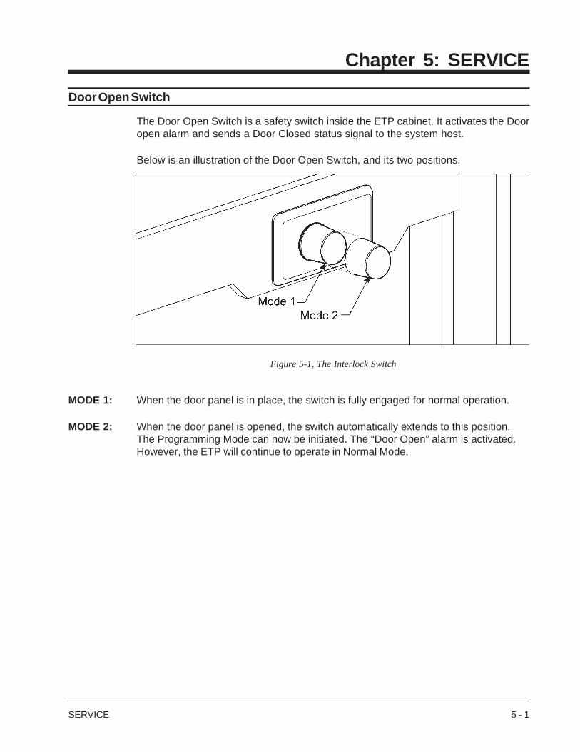
Figure 5-1, The Interlock Switch
Chapter 5: SERVICE
Door Open Switch
The Door Open Switch is a safety switch inside the ETP cabinet. It activates the Dooropen alarm and sends a Door Closed status signal to the system host.
Below is an illustration of the Door Open Switch, and its two positions.
MODE 1: When the door panel is in place, the switch is fully engaged for normal operation.
MODE 2: When the door panel is opened, the switch automatically extends to this position.The Programming Mode can now be initiated. The “Door Open” alarm is activated.However, the ETP will continue to operate in Normal Mode.
5 - 2 SERVICE
Ticket Restocking
The Low Ticket Indicator (“L”) will be displayed in the bottom right corner of the displayscreen when the ticket stock is low.
A message will appear on the display if the ETP is out of tickets.
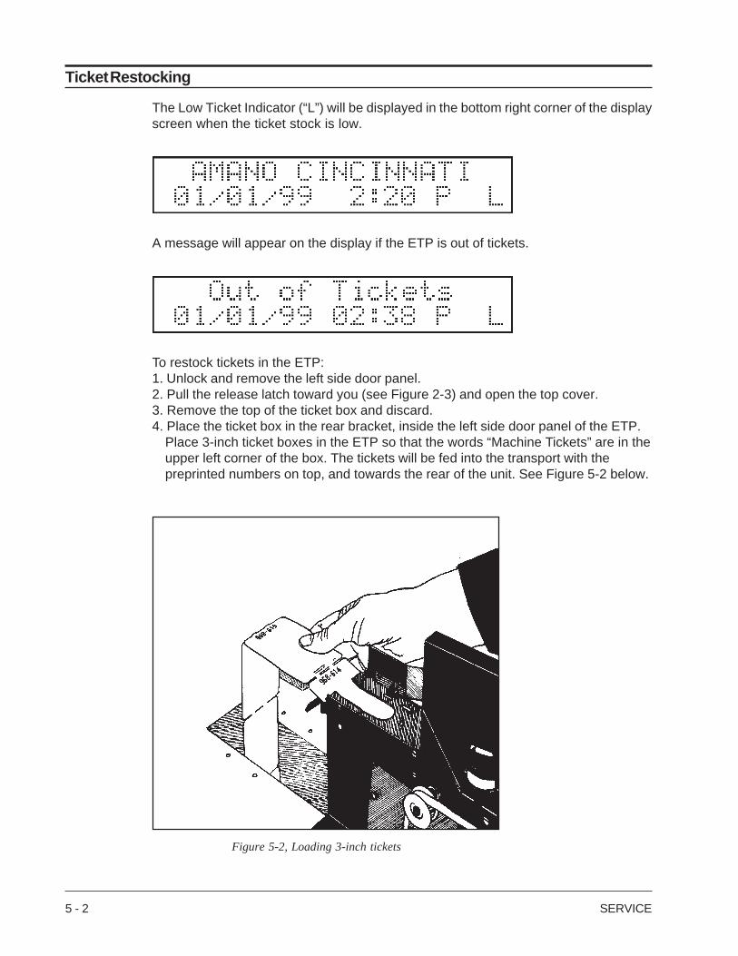
To restock tickets in the ETP:1. Unlock and remove the left side door panel.2. Pull the release latch toward you (see Figure 2-3) and open the top cover.3. Remove the top of the ticket box and discard.4. Place the ticket box in the rear bracket, inside the left side door panel of the ETP.
Place 3-inch ticket boxes in the ETP so that the words “Machine Tickets” are in theupper left corner of the box. The tickets will be fed into the transport with thepreprinted numbers on top, and towards the rear of the unit. See Figure 5-2 below.
Figure 5-2, Loading 3-inch tickets
SERVICE 5 - 3
Ticket Restocking (con't.)
5. Make sure the Low Ticket Indicator switch is engaged when you place the box inthe rear bracket (listen for a “click”). The Low Ticket Indicator “L” on the display willdisappear.
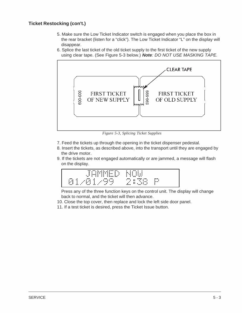
6. Splice the last ticket of the old ticket supply to the first ticket of the new supplyusing clear tape. (See Figure 5-3 below.) Note: DO NOT USE MASKING TAPE.
Figure 5-3, Splicing Ticket Supplies
7. Feed the tickets up through the opening in the ticket dispenser pedestal.8. Insert the tickets, as described above, into the transport until they are engaged by
the drive motor.9. If the tickets are not engaged automatically or are jammed, a message will flash
on the display.
Press any of the three function keys on the control unit. The display will changeback to normal, and the ticket will then advance.
10. Close the top cover, then replace and lock the left side door panel.11. If a test ticket is desired, press the Ticket Issue button.
5 - 4 SERVICE
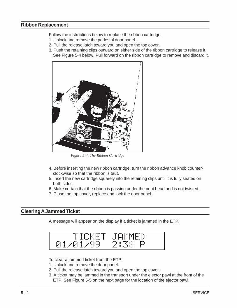
Figure 5-4, The Ribbon Cartridge
Ribbon Replacement
Follow the instructions below to replace the ribbon cartridge.1. Unlock and remove the pedestal door panel.2. Pull the release latch toward you and open the top cover.3. Push the retaining clips outward on either side of the ribbon cartridge to release it.
See Figure 5-4 below. Pull forward on the ribbon cartridge to remove and discard it.
4. Before inserting the new ribbon cartridge, turn the ribbon advance knob counter-clockwise so that the ribbon is taut.
5. Insert the new cartridge squarely into the retaining clips until it is fully seated onboth sides.
6. Make certain that the ribbon is passing under the print head and is not twisted.7. Close the top cover, replace and lock the door panel.
Clearing A Jammed Ticket
A message will appear on the display if a ticket is jammed in the ETP.
To clear a jammed ticket from the ETP:1. Unlock and remove the door panel.2. Pull the release latch toward you and open the top cover.3. A ticket may be jammed in the transport under the ejector pawl at the front of the
ETP. See Figure 5-5 on the next page for the location of the ejector pawl.
SERVICE 5 - 5
Clearing A Jammed Ticket (con't.)
4. Carefully hold the top of the pawl back to release the jammed ticket.5. Press any of the function keys on the Control Unit. The ticket will automatically
advance.6. If the ticket does not advance automaticaly, hold the top of the pawl back and
remove the jammed ticket by hand, then press any function key.7. Close the top cover, replace and lock the door panel.
Issuing Lost Tickets
If a customer loses a ticket, a replacement “lost ticket” is needed to validate at the exit.The ETP gives you the option of issuing replacement lost tickets in advance. Follow theinstructions below to issue lost tickets.
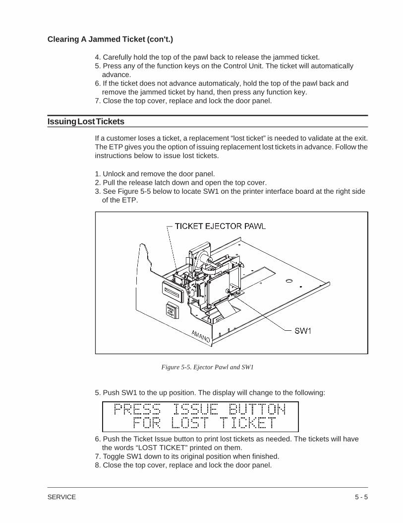
1. Unlock and remove the door panel.2. Pull the release latch down and open the top cover.3. See Figure 5-5 below to locate SW1 on the printer interface board at the right side
of the ETP.
Figure 5-5. Ejector Pawl and SW1
5. Push SW1 to the up position. The display will change to the following:
6. Push the Ticket Issue button to print lost tickets as needed. The tickets will havethe words “LOST TICKET” printed on them.
7. Toggle SW1 down to its original position when finished.8. Close the top cover, replace and lock the door panel.

5 - 6 SERVICE
OPTIONS SPECIFICATIONS A - 1
Appendix A: OPTIONS SPECIFICATIONS
Option J - Magnetic Reader
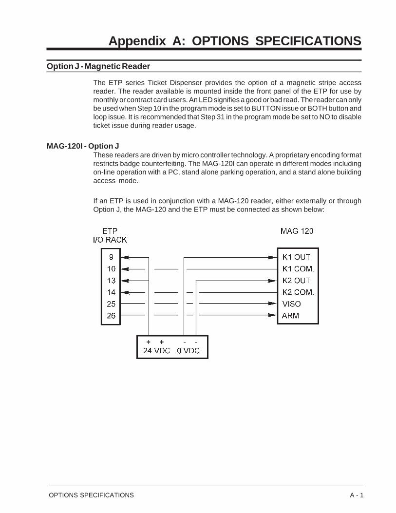
The ETP series Ticket Dispenser provides the option of a magnetic stripe accessreader. The reader available is mounted inside the front panel of the ETP for use bymonthly or contract card users. An LED signifies a good or bad read. The reader can onlybe used when Step 10 in the program mode is set to BUTTON issue or BOTH button andloop issue. It is recommended that Step 31 in the program mode be set to NO to disableticket issue during reader usage.
MAG-120I - Option JThese readers are driven by micro controller technology. A proprietary encoding formatrestricts badge counterfeiting. The MAG-120I can operate in different modes includingon-line operation with a PC, stand alone parking operation, and a stand alone buildingaccess mode.
If an ETP is used in conjunction with a MAG-120 reader, either externally or throughOption J, the MAG-120 and the ETP must be connected as shown below:
A - 2 OPTIONS SPECIFICATIONS
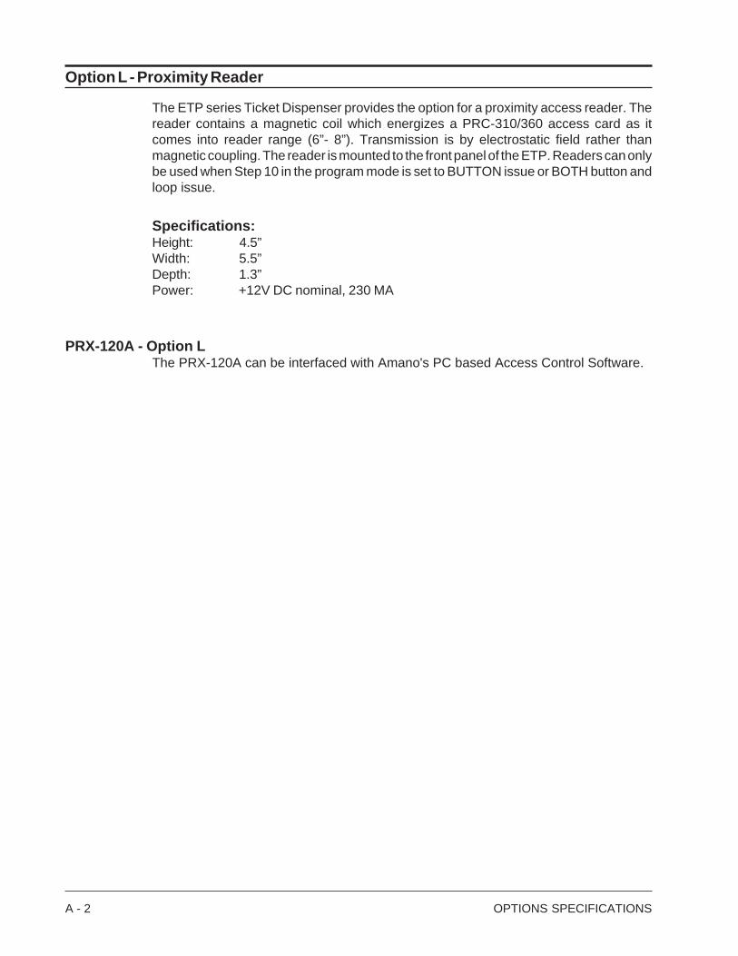
Option L - Proximity Reader
The ETP series Ticket Dispenser provides the option for a proximity access reader. Thereader contains a magnetic coil which energizes a PRC-310/360 access card as itcomes into reader range (6”- 8”). Transmission is by electrostatic field rather thanmagnetic coupling. The reader is mounted to the front panel of the ETP. Readers can onlybe used when Step 10 in the program mode is set to BUTTON issue or BOTH button andloop issue.
Specifications:Height: 4.5”Width: 5.5”Depth: 1.3”Power: +12V DC nominal, 230 MA
PRX-120A - Option LThe PRX-120A can be interfaced with Amano's PC based Access Control Software.

ACCESSORIES SPECIFICATIONS B - 1
Appendix B: ACCESSORIES SPECIFICATIONS
KIT-30: Intercom Kit
The ETP can be equipped with an AIPHONE model LE-DA intercom system. Theintercom is mounted to the inside of the ETP front panel. A call button is included for thecustomer at the ETP. A call tone will signal the master station(s) as long as the call buttonis being pushed. Once the master station replies, communication with the ETP intercomis hands-free. Detailed installation and operation instructions are included with the unit.
Specifications:Height: 4-1/2”Width: 4-9/16”Depth: 1-9/16”Wiring: DO NOT CONNECT ANY TERMINAL ON ANY INTERCOM
UNIT TO AC POWER.• 2 conductors needed for a single-master system. (Shorting link remains attached.)• 3 conductors needed for intermixed system. (Remove shorting link.)
See the table below for wire specifications:
Precautions:• Do not splash water on the intercom unit from a hose, bucket, or etc.• Clean intercom unit with a soft cloth dampened with neutral household cleanser. Never use a solvent such as lacquer thinner or benzene.
B - 2 ACCESSORIES SPECIFICATIONS
KIT-72 - Voice Message
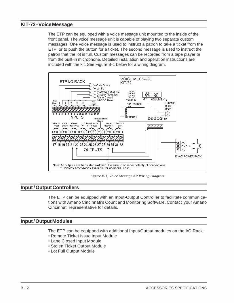
The ETP can be equipped with a voice message unit mounted to the inside of thefront panel. The voice message unit is capable of playing two separate custommessages. One voice message is used to instruct a patron to take a ticket from theETP, or to push the button for a ticket. The second message is used to instruct thepatron that the lot is full. Custom messages can be recorded from a tape player orfrom the built-in microphone. Detailed installation and operation instructions areincluded with the kit. See Figure B-1 below for a wiring diagram.
Figure B-1, Voice Message Kit Wiring Diagram
Input / Output Controllers
The ETP can be equipped with an Input-Output Controller to facilitate communica-tions with Amano Cincinnati's Count and Monitoring Software. Contact your AmanoCincinnati representative for details.
Input / Output Modules
The ETP can be equipped with additional Input/Output modules on the I/O Rack.• Remote Ticket Issue Input Module• Lane Closed Input Module• Stolen Ticket Output Module• Lot Full Output Module
TICKET SPECIFICATIONS C - 1
Appendix C: TICKET DIMENSIONS
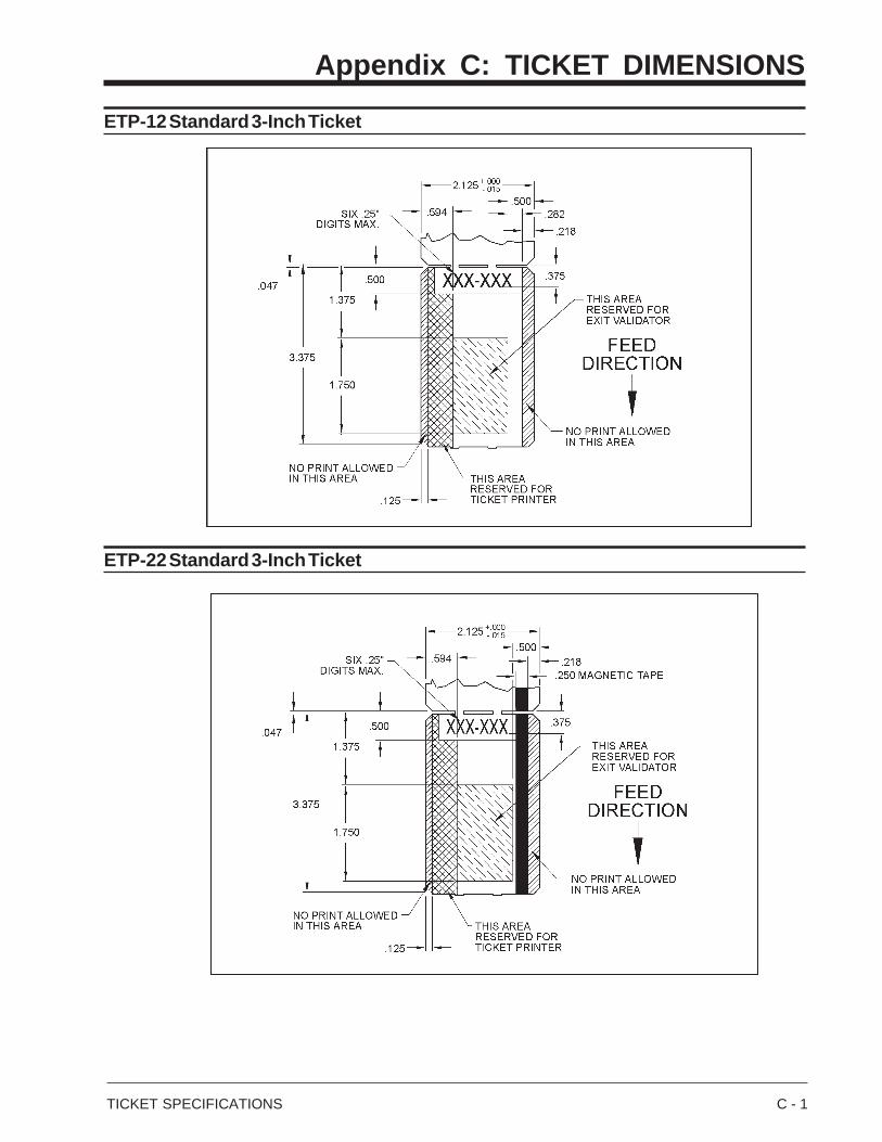
ETP-12 Standard 3-Inch Ticket
ETP-22 Standard 3-Inch Ticket

C - 2 TICKET SPECIFICATIONS

AMANO CINCINNATI, INC.A Company of the AMANO Group/Yokohama140 Harrison Avenue, Roseland, NJ 07068
Atlanta Sales Office(770) 587-1082 • (800) 554-1031
Chicago Sales Office(847) 718-1100 • (800) 323-8864
Cincinnati Sales Office(513) 697-9000 • (800) 487-7564
Dallas Sales Office(972) 241-9146 • (800) 527-4037
Los Angeles Sales Office(714) 970-2280 • (800) 854-5977
New Jersey Sales Office(973) 403-1900 • (800) 526-2559
Toronto Sales Office(905) 624-4085 • (800) 387-3388
M20053-03 - Version H2.9 • Copyright © 1999 • Printed in U.S.A. • 8/99/300