Ethernut Version 2.1 Hardware User`s Manualpub.ucpros.com/download/ethwm21e.pdf · Ethernut...
33
Ethernut Version 2.1 Hardware User`s Manual
Transcript of Ethernut Version 2.1 Hardware User`s Manualpub.ucpros.com/download/ethwm21e.pdf · Ethernut...

Ethernut Version 2.1
Hardware User`s Manual

Manual Revision: 1.2Issue date: January 2005
Copyright 2003-2005 by egnite Software GmbH. All rights reserved.
egnite makes no warranty for the use of its products and assumes noresponsibility for any errors which may appear in this document nor does it makea commitment to update the information contained herein.egnite products are not intended for use in medical, life saving or life sustainingapplications.egnite retains the right to make changes to these specifications at any time,without notice.All product names referenced herein are trademarks of their respectivecompanies. Ethernut is a registered trademark of egnite Software GmbH.

Contents
About the Ethernut 2.1 Board . . . . . . . . . . . . . . . . . . . . . . . . . . . . . . . . . . . . . . .1Ethernut Features . . . . . . . . . . . . . . . . . . . . . . . . . . . . . . . . . . . . . . . . . . . . . . .1Block Diagram . . . . . . . . . . . . . . . . . . . . . . . . . . . . . . . . . . . . . . . . . . . . . . . . .2LED Indicators . . . . . . . . . . . . . . . . . . . . . . . . . . . . . . . . . . . . . . . . . . . . . . . . .2Serial Ports . . . . . . . . . . . . . . . . . . . . . . . . . . . . . . . . . . . . . . . . . . . . . . . . . . . .3Ethernet Port . . . . . . . . . . . . . . . . . . . . . . . . . . . . . . . . . . . . . . . . . . . . . . . . . . .3Expansion Port . . . . . . . . . . . . . . . . . . . . . . . . . . . . . . . . . . . . . . . . . . . . . . . . .3Power Supply . . . . . . . . . . . . . . . . . . . . . . . . . . . . . . . . . . . . . . . . . . . . . . . . . .4Watchdog Timer . . . . . . . . . . . . . . . . . . . . . . . . . . . . . . . . . . . . . . . . . . . . . . . .5System Clock . . . . . . . . . . . . . . . . . . . . . . . . . . . . . . . . . . . . . . . . . . . . . . . . . .5Flash ROM . . . . . . . . . . . . . . . . . . . . . . . . . . . . . . . . . . . . . . . . . . . . . . . . . . . .5Static RAM . . . . . . . . . . . . . . . . . . . . . . . . . . . . . . . . . . . . . . . . . . . . . . . . . . . .5EEPROM . . . . . . . . . . . . . . . . . . . . . . . . . . . . . . . . . . . . . . . . . . . . . . . . . . . . . .5Configuration Jumpers . . . . . . . . . . . . . . . . . . . . . . . . . . . . . . . . . . . . . . . . . .5Upgrading from Previous Ethernut Revisions . . . . . . . . . . . . . . . . . . . . . . .6
Quick Start . . . . . . . . . . . . . . . . . . . . . . . . . . . . . . . . . . . . . . . . . . . . . . . . . . . . . . .7Prerequisites for Operation . . . . . . . . . . . . . . . . . . . . . . . . . . . . . . . . . . . . . . .7Precautions . . . . . . . . . . . . . . . . . . . . . . . . . . . . . . . . . . . . . . . . . . . . . . . . . . . .7Board Installation . . . . . . . . . . . . . . . . . . . . . . . . . . . . . . . . . . . . . . . . . . . . . . .7
Testing the Board . . . . . . . . . . . . . . . . . . . . . . . . . . . . . . . . . . . . . . . . . . . . . . . .10Ethernet Controller Read/Write Loop . . . . . . . . . . . . . . . . . . . . . . . . . . . . . .10Jump to Bootloader . . . . . . . . . . . . . . . . . . . . . . . . . . . . . . . . . . . . . . . . . . . .11SRAM Read/Write Loop . . . . . . . . . . . . . . . . . . . . . . . . . . . . . . . . . . . . . . . . .11Send Broadcasts Loop . . . . . . . . . . . . . . . . . . . . . . . . . . . . . . . . . . . . . . . . . .11Exit BaseMon . . . . . . . . . . . . . . . . . . . . . . . . . . . . . . . . . . . . . . . . . . . . . . . . .11
Network Configuration . . . . . . . . . . . . . . . . . . . . . . . . . . . . . . . . . . . . . . . . . . . .12DHCP/BOOTP Method . . . . . . . . . . . . . . . . . . . . . . . . . . . . . . . . . . . . . . . . . .13Fixed IP Address . . . . . . . . . . . . . . . . . . . . . . . . . . . . . . . . . . . . . . . . . . . . . .13ARP Method . . . . . . . . . . . . . . . . . . . . . . . . . . . . . . . . . . . . . . . . . . . . . . . . . .13Testing Network Operation . . . . . . . . . . . . . . . . . . . . . . . . . . . . . . . . . . . . . .14
Jumper Configuration . . . . . . . . . . . . . . . . . . . . . . . . . . . . . . . . . . . . . . . . . . . .15Jumper Overview . . . . . . . . . . . . . . . . . . . . . . . . . . . . . . . . . . . . . . . . . . . . . .15Serial Ports . . . . . . . . . . . . . . . . . . . . . . . . . . . . . . . . . . . . . . . . . . . . . . . . . . .15JTAG Port . . . . . . . . . . . . . . . . . . . . . . . . . . . . . . . . . . . . . . . . . . . . . . . . . . . .18
Hardware Expansion . . . . . . . . . . . . . . . . . . . . . . . . . . . . . . . . . . . . . . . . . . . . . .20Expansion Port . . . . . . . . . . . . . . . . . . . . . . . . . . . . . . . . . . . . . . . . . . . . . . . .20Analog Input Port . . . . . . . . . . . . . . . . . . . . . . . . . . . . . . . . . . . . . . . . . . . . . .21
Troubleshooting . . . . . . . . . . . . . . . . . . . . . . . . . . . . . . . . . . . . . . . . . . . . . . . . .22
Schematic . . . . . . . . . . . . . . . . . . . . . . . . . . . . . . . . . . . . . . . . . . . . . . . . . . . . . .26

About the Ethernut 2.1 Board
About the Ethernut 2.1 Board
Low-ccost Ethernet capability can be added to many embedded applications.
Since its introduction in the year 2000, Ethernut boards have been used todevelop some of the most innovative products. Using the hardware, firmware,software and tools, developers have everything they need to develop leadingnetworked devices rapidly and affordably. The board is well suited forapplication development in a wide range of applications. Some areas are:
Networked sensors
Remote monitoring equipment
Alarm service providing
Remote diagnose and service
Industrial Ethernet applications
Home and building control
Ethernut Features
Ethernut 2.1 is a small (80 x 100 mm) board combining Atmel's ATmega128 RISCmicrocontroller with SMSC's LAN91C111 Ethernet controller. The main featuresare:
ATmega 128 RISC microcontroller with up to 16 MIPS throughput
Full duplex IEEE 802.3 compliant 10/100 Mbps Ethernet controller with on-board RJ- 45 connector
Two serial ports, RS-232 at DB-9 connector and half duplex RS-485 at screwterminal
128 kByte in-system programmable Flash ROM and 512 kByte serialDataflash
4 kByte in-system programmable EEPROM
32 kByte SRAM plus 480 kByte banked SRAM
22 programmable digital I/O lines
8-channel, 10-bit analog/digital converter
Two 8-bit and two 16-bit timer/counters
Watchdog timer for enhanced reliability
LED indicators for power supply and Ethernet activity
Single power supply DC 8-12V
1

Ethernut Hardware Manual
2
Block Diagram
The block diagram shows the main components.
Definitely the most important part is the ATmega 128 microcontroller. It’s a quitecomplex chip and described in detail in Atmel’s ATmega 128 data sheet. Almostall pins are routed to the Ethernut expansion port, a 64-pin connector, which canbe used to add custom hardware like the Medianut MP3 decoder with LCDinterface.
The microcontroller provides two UART channels, which are routed to the on-board RS-232 and RS-485 level shifters.
A Xilinx CPLD is used to implement the bank select logic of the external 512kByte SRAM and generates the chip select of the LAN Controller.
While Ethernut’s software offers serveral bootloader capabilities over RS-232 orEthernet, program code is initially uploaded through the JTAG interface. Theconnector layout conforms to Atmel’s 10-pin JTAG interface. Unfortunately thesame type of connector is used by Atmel for the ISP interface.
WARNING: Never plug an ISP programming adapter in to theEthernut 2.1 JTAG connector. This will result in a power supplyshortcut and will at least blow the fuse on the Ethernut board.

About the Ethernut 2.1 Board
LED Indicators
The Ethernut 2 board is equipped with three LEDs. For historical reason, theseLEDs are named LED1, LED3 and LED4, while LED2 doesn’t exist.
The red LED1 is directly connected to the power supply. It is lit when power isapplied to the board.
A green and a yellow LED (LED3 and LED4 resp.) are used to indicate activity onthe Ethernet port. The yellow LED indicates the network link status and is litwhen the link status is OK. The green LED indicates receive and transmit activityfrom and to the network.
Serial Ports
Ethernut provides an on-board DB-9 connector for RS-232 serial communicationas well as a screw terminal for RS-485 half duplex communication. IC6 is used toconvert the required voltage levels for RS-232 from the 5V power supply, whileIC7 provides the signal conversion for the RS-485 interface.
Any of the two serial interfaces of the microcontroller can be routed to the RS-232 or the RS-485 connector. In the default jumper configuration the firstinterface (UART0) is routed to the RS-232 connector while the second interface(UART1) is not used.
Ethernet Port
Ethernut provides an on-board modular RJ-45 connector for its twisted pairEthernet port. This port is connected to the SMSC LAN91C111 Ethernet controllervia a 100/10Base-T transformer/filter. The interface supports the maximum cablelength of 100 meters between the Ethernet board and a hub.
Expansion Port
Add-on boards can be added to the expansion port. These boards may containsimple I/O circuits driven by the Ethernut board, or may be equipped with theirown processor, using the Ethernut board as an Ethernet I/O processor only.
3

Ethernut Hardware Manual
4
Power Supply
The complete logic of the Ethernut board is driven by 5V and 3.3V power supply.The board provides its own voltage regulators (IC8 and IC9). It only requires anunregulated power supply of DC 8-12V with a minimum current of 400 mA.
Four different methods may be used to connect an external power supply.
1 A standard 2.1 mm barrel connector. This input is protected by a fuse (F1), afast transient voltage suppressor (D3) and a rectifier bridge (D4, D5, D6 and D7).
2 A screw terminal. Pins 1 and 2 and pins 2 and 3 of jumper JP6 must beshortened. When both jumpers are set, this is an unprotected input. Applying awrong polarity or a too high voltage will destroy the Ethernut board. Typicallythis is used to supply external RS485 devices, in which case only pins 2 and 3are shortened, but not pins 1 and 2.
3 Using pins 4, 5 and pins 7, 8 of the Ethernet twisted pair connector. In thiscase pins 1 and 3 and pins 2 and 4 of jumper JP3 must be shortened. Like thebarrel connector, this input is fully protected. A special power supply injector isrequired for the Ethernet cable. Do not set jumpers on JP3 without such aninjector. You may destroy other equipment attached to the Ethernet cable.
4 The DC signal is routed to the Ethernut expansion connector to either supplyadd-on boards or to receive power supply from an add-on board. Like the screwterminal, this input is unprotected.
As soon as power is attached to any of the inputs mentioned above, the redLED1 will lit.
�
�
�
�

About the Ethernut 2.1 Board
Watchdog Timer
Software bugs, temporary hardware failures caused by electrical transients orinterference and many other problems might cause the system to malfunction.The ATmega128 microcontroller (IC1) provides an on-chip watchdog timer, whichforces a system reset, if the application program fails to periodically update thistimer.
System Clock
The ATmega 128 microcontroller clock is generated by a 14.7456 MHz crystal(Q1), which may be replaced by a crystal of up to 16 MHz. An additional 32.768kHz crystal (Q2) drives an on-chip asynchronous timer, which is typically used fora software realtime clock. The Ethernet controller is driven by a separate 20-MHzcrystal (Q3).
Flash ROM
The ATmega 128 provides 128 kBytes of on-chip, non-volatile flash memoryspace, which is used for program code and read-only data storage. This memoryis organized as 64K x 16 bits and can be (re-)programmed through in-systemprogramming.
Static RAM
The Ethernut board provides 512 kByte SRAM (IC4), which is used as read/writedata storage. The lower 4 kBytes are overlayed by the ATmega128 internalregister and SRAM space. The required address latch is provided by the CPLD(IC3).
With its 16 bit address bus the ATmega128 can address up to 64 kByte RAMonly. The lower 32 kByte on the Ethernut board are fixed.
EEPROM
The ATmega 128 provides 4 kBytes of on-chip, non-volatile, electrically erasablememory, typically used for configuration data storage. This memory providesread/write access under program control as well as through in-systemprogramming. Note, that EEPROM write access is much slower (about 2.5 ms)than writing to SRAM.
Configuration Jumpers
For maximum flexibility, the board is equipped with 5 jumper areas.
JP1 configures the connection to the two serial devices (UART).JP2 is used to select the port bit of the RS485 direction signal.JP3 enables power supply over Ethernet cable.JP5 is used to specify the JTAG chain.JP6 configures the RS485 screw terminal.
WARNING: Note, that changing any crystal will alter the Ethernutboard's EMC characteristics and require re-testing.
5

Ethernut Hardware Manual
6
JP4 had been used on previous board revisions to select between ISP and JTAGprogramming. Ethernut 2.1 doesn’t provide an ISP connector and thus JP4 hadbeen removed.
Upgrading from Previous Ethernut Revisions
Ethernut has undergone many changes since its initial release in the year 2000,but board dimensions and positions of main connectors remained unchanged.
Also, the software still supports all previous Ethernut Boards, even revision 1.1with the ATmega 103 microcontroller, which is no longer in production.However, there are a few things to consider.
The most important change to notice is, that you can’t use programmingadapters shipped with previous starter kits, because Ethernut 2.1 isprogrammable via JTAG only. ISP is not supported. Never plug your ISP adapterinto Ethernut 2.1.
Upgrading from Ethernut 2.0 is trouble-free. Bit 4 of PORTB is used as a highactive chip select for the additional data flash. You may either wire a differentport bit for this purpose or ask your distributor for Ethernut 2.1 boards withoutdata flash.
Upgrading from Ethernut 1 additionally requires a very few application codechanges only in the initialization part, where references to the RTL8019AS haveto be replaced by the LAN91C111.

Quick Start
Quick Start
This chapter will help you quickly set up and start using the Ethernut board.
Prerequisites for Operation
The following items are necessary to run the Ethernut board:
A standard PC equipped with Linux or Windows, an available serial COMport and a twisted pair Ethernet adapter card.
Terminal emulation software, such as TeraTerm or Hyperterminal.
An unregulated power supply matching your local mains. It should supplyDC 8-12V, 300 mA minimum, on a standard 2.1 mm barrel connector.
Two straight-through twisted pair cables together with 100 or 10 Base-T hubor switch or a twisted pair cross cable, if you don't got a hub or switch.
The following items are included in the Ethernut Starter Kit:
A JTAG compatible programming adapter.
A straight through serial communication cable with a DB-9 female on oneend and a DB-9 male connector on the other.
It is further assumed, that you got some basic knowledge about digital hardwareand TCP/IP networking. This manual will not present any of these basics, but youcan find excellent books or web resources about these topics.
Precautions
Born out of an Open Source Project, the Ethernut board is a commercial product,from which you expect some kind of fail safe operation. But also keep in mind,that a bare electronic circuit is a fragile product, which demands carefulhandling. In the first place learn how to avoid problems caused by electrostaticdischarge.
Moreover, no limitations are applied to chip programming, which may guard youagainst accidents. In particular, the ATmega 128 microcontroller may becompletely disabled by misprogramming its fuses. Thus we strictly recommendnot to change the fuse settings, if you are not absolutely sure what you aredoing.
The following fuses had been enabled (programmed to zero) before shipping theboard: JTAGEN, SPIEN, BOOTSZ1, BODLEVEL, BODEN and CKOPT. All otherfuses remain unprogrammed (erased to one).
7

Ethernut Hardware Manual
8
Board Installation
1 Remove the board from the antistatic bag. Visually inspect the board to verifythat it was not damaged during shipment. Do not use the antistatic bag as aunderlying pad for Ethernut, because it’s electroconductive. Put the board on awooden surface or simply on a piece of paper. Plastic surfaces may be harmfulbecause of electrostatic discharge.
2 Connect Ethernut`s DB-9 RS232 port to an available COM port using the serialcable.
3 Use one twisted pair cable to connect Ethernut's RJ-45 connector to the hubor switch and the other twisted pair cable to connect the hub or switch with thenetwork adapter in the PC. If you are not using a hub or switch, then directlyconnect the Ethernut board with the PC’s network adapter using a twisted paircross cable.
4 Connect the power supply to the barrel connector on the Ethernut board. TheEthernut board is equipped with its own rectifier bridge and voltage regulator.Therefore the polarity of the barrel connector isn't important.
5 Apply power to the Ethernut board by connecting the power supply to anelectrical outlet. When the board is powered up, the red power LED (LED1)should go on.
6 Start the terminal emulation program at 38400 baud or any higher rate up to115200 baud, no parity, 8 data bits, and 1 stop bit. Disable hardware (RTS/CTS)and software (XON/XOFF) flow control.
WARNING: The power supply should not be plugged into an electricaloutlet before connecting it to the Ethernut board.
WARNING: As with all computer equipment, the Ethernut board maybe severely damaged by electrostatic discharge (ESD). Be sure to takeproper precautions before removing the Ethernut board from theantistatic bag. Never pass the board from one person’s hand toanother.

Quick Start
7 Reset the Ethernut board by depressing and releasing the reset switch locatednear the SMSC chip. Hold down the spacebar on the terminal emulation programand wait until the BaseMon welcome message is displayed.
See the next chapter for a detailed description of the BaseMon program.
Baudrate
The baudrate of the Ethernut board is specified by the CPU crystal (Q1,14.7456 MHz by default) and a baudrate selector ranging from 0 to 255.
The actual baudrate can be calculated by
baudrate = crystal frequency / (16 * (selector + 1))
Running at 14.7456 MHz, a selector value of 23 gives a baudrate of 38400Baud:
38400 = 14745600 / (16 * (1 + 1))
The Basemon program provides a simple automatic baudrate selection bychanging the selector from zero to 71, while trying to receive a spacecharacter. If no space character could be received within about a minute, thenthe default selector 23 is set (38400 Baud at 14.7456 MHz).
9

Ethernut Hardware Manual
10
Testing the Board
Using the preloaded BaseMon firmware to test the Ethernut hardware.
When using a terminal emulation program like described in the previous chapter,hold down the space bar on the PC keyboard and press and release the resetbutton on the Ethe
rnut board. This is the tiny push button at the board’s edge near the screwterminal. After some seconds the following output should appear in the terminalemulation window:
BaseMon 4.0.2Nut/OS 3.4.2.1Baudrate select = 23External RAM Test... 44800 bytesBanked RAM Test... 30 banks, 16384 bytes ea.Detecting NIC... LAN91C111 Testing NIC... OKI/O Port Test... OK
Press any of the following keys:B - Send broadcastsE - Ethernet controller read/writeJ - Jump to bootloaderS - SRAM read/writeX - Exit BaseMon, configure network and start WebServer
Depending on the preloaded version and the baudrate, your output may slightlydiffer. But the amount of RAM should match and all tests should report the resultOK.
The menu will not appear, if BaseMon didn’t receive a space character or failedto determine the baudrate. Check again the configuration of the terminalemulation program and make sure that all handshakes are disabled. Sometimesthe keyboard repeat rate of the PC is too slow, in which case BaseMon isn’t ableto verify the baudrate. If you don’t know how to increase this rate, thumb on thespace bar as fast as you can. Replacing the Beethoven sound from your MP3player by a record from Metallica or Pantera will be helpful.
Nevertheless, if BaseMon is unable to receive three consecutive space charactersat the same baudrate, it will continue at 38,400 Baud. In this case it will notdisplay the menu, nor wait for any further input, but display the test results andthen immediately start the build-in webserver.
Unlike some other embedded monitors, BaseMon is not resident. You will laterupload other sample applications or your own code, which overwrite BaseMon.Whenever you are not sure, whether any problems may arise from hardware orsoftware failures, it’s always a good idea to upload the BaseMon hex file againfor running the integrated tests. The menu offers further tests, which will bedescribed now.

Testing the Board
Ethernet Controller Read/Write Loop
When pressing E on the BaseMon menu, the Ethernut board will enter anendless loop, trying to read the revision ID of the Ethernet controller at baseaddress C000 hex:
rev=0x91
The loop keeps running until a key is pressed in the terminal emulation programand may be used to check the board's address and data bus signals with anoscilloscope or logic analyzer.
Jump to Bootloader
When pressing J on the BaseMon menu, the program will jump to flash memorylocation 1F000 hex. Fully assembled Ethernut boards are delivered with apreloaded bootloader, which uses DHCP/BOOTP/TFTP to load a new flash ROMimage. Note, that the bootloader will be deleted by the chip erase command,which is typically required before uploading a new application.
SRAM Read/Write Loop
When pressing S on the BaseMon menu, the Ethernut board enters an endlessloop, doing a walking bit test on all address and data bus lines. The loop keepsrunning until a key is pressed in the terminal emulation program and may beused to check the board's address and data bus signals with an oscilloscope orlogic analyzer.
Send Broadcasts Loop
When pressing B on the BaseMon menu, the Ethernut board will initialize theEthernet Controller and start sending Ethernet broadcasts in an endless loop. Theyellow link LED will lit and the green activity LED will start flashing. The terminalemulation window will show the progress. The loop keeps running until a key ispressed in the terminal emulation program and may be used to check theboard's Ethernet output with an oscilloscope.
Exit BaseMon
Pressing X on the BaseMon menu will quit the BaseMon program, initialize theNut/OS operating system and Nut/Net TCP/IP stack and finally enter a sampleHTTP daemon application. However, before that is done, BaseMon queries aMAC address, IP address, network mask and default route:
MAC address (000698000000):IP address (0.0.0.0):Net mask (255.255.255.0):Default route (0.0.0.0):
The last six digits of the MAC address are written on the board. Enter these sixdigits on the MAC address prompt. On all prompts, you may simply press enterto confirm the default shown in brackets, or enter other values in their decimaldotted form. If the IP address is 0.0.0.0, Ethernut will not query the network maskand default route, but request these values from a DHCP server. This requires ofcourse, that a DHCP server is running in your local network.
Network configuration is discussed in more detail in the next chapter.11

Ethernut Hardware Manual
12
Network Configuration
This chapter shows different methods to configure Ethernut`s networkparameters.
In order to communicate over a TCP/IP network, the Ethernut board needs aunique IP address. It is important, that this address is not used by any other nodeon the network.
Changing the network configuration requires user interaction, either bykeyboard/LCD interface, web browser, RS-232 communication or whatever thefinal system may provide. It’s up to the specific application to deal with thesevalues. Nut/OS just provides a common framework. The BaseMon applicationexplained in the previous chapter uses RS-232, for example.
The TCP/IP configuration is stored in EEPROM and contains the following values(Nut/OS Version 4.2).
Default values will be used by the software when the EEPROM has beenpreviously erased. When Ethernuts are shipped, the EEPROM contains the valuesfrom the final test. The last used IP address is set to 192.168.192.x, with x varyingbetween 100 and 254. The MAC address will be the one, that has been uniquelyassigned to your board. You can find it in your invoice too and the last six digitsare written on the board. The configured IP address is set to 0.0.0.0, whichautomatically enables DHCP.
A MAC address, also referred to as the hardware or Ethernet address is aunique 48 bit number assigned to every Ethernet node. The upper 24 bits arethe manufacturer's ID, assigned by the IEEE Standards Office. The ID ofEthernut boards manufactured by egnite Software GmbH is 000698hexadecimal. The lower 24 bits are the board's unique ID assigned by themanufacturer of the board. Boards produced by egnite do have a unique ID,which is written on the board.
Name Type Default Description
size Byte value 31Total size of theconfiguration structure.Used to check validity.
nameCharacterarray
eth0Name of the networkinterface. Maximum size is8 characters.
mac Byte array 0006980000006 bytes unique MACaddress.
ip_addr IP address 0.0.0.0 Last used IP address.
ip_mask IP address 255.255.255.0 Configured IP mask.
gateway IP address 0.0.0.0 Default gateway IP.
cip_addr IP address 0.0.0.0 Configured IP address.

Network Configuration
The ATmega 128 microcontroller offers a number of programmable flags tochange general modes. One of these flags disables EEPROM erasure during chiperase and has been set before shipping the board. Thus, if the chip is erased inorder to upload a new application, the EEPROM contents is preserved and re-used by the new application.
DHCP/BOOTP Method
This is the preferred method. As explained, the configured IP of shippedEthernuts is set to 0.0.0.0, which enables DHCP/BOOTP. If a DHCP server existson the network, Ethernut will automatically request its IP address, the IP addressof the standard gateway, and the IP mask of the local network. If no DHCP servercould be located, the board will reuse the last used address. If this is 0.0.0.0 or ifthe EEPROM had been erased, then Ethernut switches to the ARP method.
Fixed IP Address
If DHCP service is not available, you should assign a fixed IP address. Before youcreate your own applications with fancy user interfaces to set this address, youcan use BaseMon. The EEPROM configuration will be preserved whenreprogramming the Ethernut and will be reused by the new applications.
ARP Method
This method can be used as a last resource. If the Ethernut's EEPROM containsno configuration data and no DHCP server is available on the network, then theARP method may be helpful to set the board's IP address. In this mode theEthernut board set its address from the first ICMP packet it receives.
To set the Ethernut's IP address by the ARP method, an ARP entry can bemanually created on the PC and then a ping packet is sent from the PC to theEthernut board.
Enter the following command to manually create an ARP entry for an Ethernutboard with a MAC address of 00:06:98:00:00:00 and an IP address of192.168.171.5 on a LINUX command line shell:
arp -s 192.168.171.5 00:06:98:00:00:00
On a Windows DOS prompt this command is slightly different:
arp -s 192.168.171.5 00-06-98-00-00-00
The next command to enter is the same on both systems:
ping 192.168.171.5
The first ping packet that arrives at the Ethernut board with the MAC address of00:06:98:00:00:00 sets the IP address of that board to 192.168.171.5. Note, that theARP method will not configure a default gateway and will fix the network maskto 255.255.255.0.
The ARP method will be used on blank EEPROMs only. After having set it once,the configuration will be stored in the EEPROM and used in the next systemstart. To enable the ARP method again, you must use your JTAG programmer toclear the EEPROM contents. Refer to the Ethernut Software Manual for furtherinformation about JTAG programming.
13

Ethernut Hardware Manual
14
Testing Network Operation
After configuring the network parameters, you can check, that the Ethernut boardis properly hooked up to the network by running ping from your PC. On a DOSprompt or command line shell, type:
ping 192.168.171.5
Instead of the above IP address use the one you configured previously. If youreceive a response without timing out, the Ethernut board is ready to try theHTTP daemon. Use any Webbrowser to query the following URL:
http://192.168.171.5/index.html
Again, instead of the above IP address use the one previously configured.

Jumper Configuration
Jumper Configuration
Adapting Ethernut to specific requirements.
Jumper Overview
For maximum flexibility, the board is equipped with 5 jumper areas. The picturebelow shows the default jumper configuration, set when Ethernuts is shipped.
JP1 configures the connection to the two serial devices (UART).JP2 is used to select the port bit of the RS485 direction signal.JP3 enables power supply over Ethernet cable.JP5 is used to specify the JTAG chain.JP6 configures the RS485 screw terminal.
JP4 had been used on previous board revisions to select between ISP and JTAGprogramming. Ethernut 2.1 doesn’t provide an ISP connector and thus JP4 hadbeen removed.
Note, that in the following pictures pin 1 is always the one in front on the leftside.
Serial Ports
Ethernut provides an on-board DB-9 connector for RS-232 serial communicationas well as a screw terminal for RS-485 half duplex communication. IC6 is used toconvert the required voltage levels for RS-232 from the 5V power supply, whileIC7 provides the signal conversion for the RS-485 interface.
Both, the RS-232 or the RS-485 connector may be connected to the first (UART0)or the second (UART1) serial device of the ATmega128. This is configured byjumper JP1.
15
Ethernut Hardware Manual
16
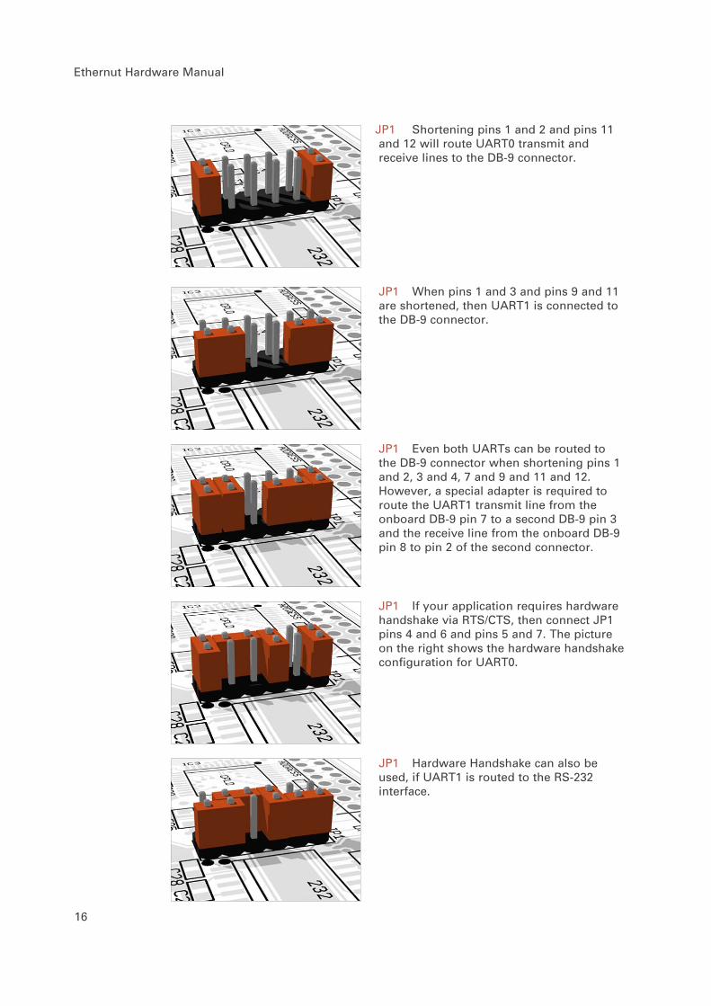
JP1 Shortening pins 1 and 2 and pins 11and 12 will route UART0 transmit andreceive lines to the DB-9 connector.
JP1 When pins 1 and 3 and pins 9 and 11are shortened, then UART1 is connected tothe DB-9 connector.
JP1 Even both UARTs can be routed tothe DB-9 connector when shortening pins 1and 2, 3 and 4, 7 and 9 and 11 and 12.However, a special adapter is required toroute the UART1 transmit line from theonboard DB-9 pin 7 to a second DB-9 pin 3and the receive line from the onboard DB-9pin 8 to pin 2 of the second connector.
JP1 If your application requires hardwarehandshake via RTS/CTS, then connect JP1pins 4 and 6 and pins 5 and 7. The pictureon the right shows the hardware handshakeconfiguration for UART0.
JP1 Hardware Handshake can also beused, if UART1 is routed to the RS-232interface.

Jumper Configuration
JP1 Most applications will probably useUART0 for RS-232 and UART1 for RS-485.This configuration is shown below. Pins 1and 2, 3 and 4, 9 and 10 and 11 and 12 ofJP1 are shortened.
JP2 The RS-485 interface is half duplex.Only two wires are needed forcommunication, but an additional port bit isrequired to switch between receive andtransmit mode. Thus pins 1 and 2 as well aspins 3 and 4 of JP2 must be shortened tocontrol the data direction via ATmega portbit PD5.
JP2 Shortening pins 5 and 6 instead ofpins 1 and 2 will use port bit PD4.
JP2 The direction signal is pulled low byR27. If pins 3 and 4 are shortened only, theRS-485 interface is configured as a receiverand no port bit for direction control isrequired.
JP6 Both ends of a RS-485communication line must be terminated bya resistor. If the Ethernut board is located atone end of the line, you must short pins 5and 6 of JP6 to enable the 120 Ohmtermination resistor (R24).
17

Ethernut Hardware Manual
18
JP6 During switching from transmit toreceive mode, the condition of the RS-485line becomes undetermined and mayintroduce problems on connected receivers.Shortening pins 7 and 8 and pins 9 and 10will enable two 560 Ohm fail safe resistors(R23 and R25). These resistors should beenabled on one end only.
JP6 Pin 3 of the screw terminal isconnected to Ethernut's signal ground via a100 Ohm resistor (R26) and can be used toconnect a cable shield. Alternatively pins 3and 4 of the screw terminal may be used toprovide power to the external RS-485device. In this case shorten pins 3 and 4 ofJP6 to disable R26 and connect screwterminal pin 3 directly to ground.
JP6 Pin 4 of the screw terminal isconnected to the Ethernut's unregulated DCline via a diode (D2). The diode protects theEthernut from supply with wrong polarity. Ifyou want Ethernut to supply externaldevices, the diode must be disabled byshortening pins 1 and 2. Be aware, that thisjumper bridge should only be set to supplyexternal devices and should always beremoved when supplying Ethernut via thescrew terminal.
JTAG Port
The angled, boxed 10-pin header connector allows serial programming of theATmega128 non-volatile Flash ROM and EEPROM as well as the CPLD withoutphysical removal of the chips from the system.
WARNING: Unlike previous board revisions, Ethernut 2.1 doesn`tsupport programming with ISP Adapters. Thus, you can`t use one ofthe programming adapters from previous Ethernut boards. Make sureto either use the programming adapter of the Ethernut 2.1 Starter Kit,Atmel`s ATJTAGICE or any other compatible JTAG adapter.Connecting an ISP adapter to the Ethernut 2.1 JTAG connector will atleast blow the board`s fuse or in worst cases destroy your Ethernut.Also note, that the adapter from the Ethernut 2.1 Starter Kit providesboth, ISP and JTAG programming, using two clearly marked cables.Never plug the ISP cable into the Ethernut 2.1 programmingconnector. Always use the cable, which is clearly marked with thelabel “JTAG”.

Jumper Configuration
19
JP5 Jumper JP5 routes the JTAG signalsto the ATmega128, if pins 1 and 2 and pins5 and 6 are shortened.
JP5 Routing the JTAG interface to theCPLD is provided by shortening pins 1 and3, 4 and 6, 7 and 8 as well as pins 9 and 10.However, you need a special Xilinx adapterfor programming the CPLD via JTAG.
JP5 As an alternative, the Ethernut is ableto program its own CPLD. The requiredjumper configuration is shown on the left.

Ethernut Hardware Manual
20
Hardware Expansion
Ethernut and custom hardware.
Many applications will do just fine with nothing else than the Ethernut orexternal hardware may be connected to the RS-232 or RS-485 port. However, ifmore is required, the Ethernut expansion port is the first choice to add customdesigned hardware.
Expansion Port
Add-on boards can be added to the expansion port. These boards may containsimple I/O circuits driven by the Ethernut board, or may be equipped with theirown processor, using the Ethernut board as an Ethernet I/O processor only.
The expansion port contains CPU data and address bus, memory read/writesignals, digital I/O ports, reset signal and power supply. Nearly allmicrocontroller pins are available at the expansion port connector, providing aninterface with lots of features like PWM, I2C (2-wire), SPI (3-wire) or counterinputs, to name just a few. It is strictly recommended to consult the ATmega 128data sheet before attaching hardware to the expansion port.
Although available at the connector, some signals are used internally by Ethernutand can’t be used by external hardware. Carefully check the schematic. Bit 5 ofPort E is used for LAN controller interrupts. You can switch this to bit 6 of thesame port by removing R2 and mounting R31 (bottom side). Bit 4 of Port B isused as a chip select for the serial data flash.
Other pins may not be available, depending on the jumper configuration. Pleaserefer to the previous chapter for additional information.
��
��
���
���
��
��
���
���
��
��
���
���
��
��
��
�
�
�
�
�
��
��
�
���
����
���
���
���
����
����
��
���
���
���
���
���
���
���
���
���
���
���
���
��
��
�� �
�
�
�
�
��
��
��
��
���
����
��
���
���
����
����

Hardware Expansion
21
The ALE signal is not available at the expansion port by default and may beconnected to pin 64 by mounting R34 on the bottom side.
The following table lists the expansion port’s pin assignment.
Analog Input Port
In order to avoid interference with typically noisy digital lines, a separateconnector is used for the microcontroller’s analog inputs.
Pin Signal Description
2 AREF Analog reference4 AGND Analog ground6 AGND Analog ground8 AGND Analog ground10 AGND Analog ground12 AGND Analog ground14 AGND Analog ground16 AGND Analog ground18 AGND Analog ground20 AGND Analog ground
Pin Signal Description
1 AVCC5 Analog supply3 AVCC5 Analog supply5 PF0 Analog input 17 PF1 Analog input 29 PF2 Analog input 311 PF3 Analog input 413 PF4 Analog input 515 PF5 Analog input 617 PF6 Analog input 719 PF7 Analog input 8
Pin Signal Description
2 VCC3 Regulated +3.3V4 VCC5 Regulated +5.0V6 GND Signal ground8 GND Signal ground10 DC Unregulated supply12 VCC5 Regulated +5.0V14 WR\ Memory write signal16 D1 Data bus bit 118 D3 Data bus bit 320 D5 Data bus bit 522 D7 Data bus bit 724 A1 Address bus bit 126 A3 Address bus bit 328 A5 Address bus bit 530 A7 Address bus bit 732 A9 Address bus bit 934 A11 Address bus bit 1136 A13 Address bus bit 1338 A15 Address bus bit 1540 PE1 Port E bit 142 PE3 Port E bit 344 PE5 Port E bit 546 PE7 Port E bit 748 PB1 Port B bit 150 PB3 Port B bit 352 PB5 Port B bit 554 PB7 Port B bit 756 PD1 Port D bit 158 PD3 Port D bit 360 PD5 Port D bit 562 PD7 Port D bit 764 NC ALE, if R34 stuffed
Pin Signal Description
1 VCC3 Regulated +3.3V3 VCC5 Regulated +5.0V5 GND Signal ground7 GND Signal ground9 MR\ Reset input11 VCC5 Regulated +5.0V13 RD\ Memory read signal15 D0 Data bus bit 017 D2 Data bus bit 219 D4 Data bus bit 421 D6 Data bus bit 623 A0 Address bus bit 025 A2 Address bus bit 227 A4 Address bus bit 429 A6 Address bus bit 631 A8 Address bus bit 833 A10 Address bus bit 1035 A12 Address bus bit 1237 A14 Address bus bit 1439 PE0 Port E bit 041 PE2 Port E bit 243 PE4 Port E bit 445 PE6 Port E bit 647 PB0 Port B bit 049 PB2 Port B bit 251 PB4 Port B bit 453 PB6 Port B bit 655 PD0 Port D bit 057 PD2 Port D bit 259 PD4 Port D bit 461 PD6 Port D bit 663 NC

Ethernut Hardware Manual
22
Troubleshooting
Problems Solution
The red LED does not goon when applying power.
The fuse may be blown. Remove anykind of attached hardware andremove all jumpers. Make sure theboard is placed on a non conductivesurface like a piece of paper.Replace the fuse (1A superfast) andsupply the board via the barrelconnector J2 only with not morethan 12V DC. Best use a lab powersupply with current control andcarefully increase the voltagestarting from 3V. The board shouldnot draw more than 300 milliamps.
The yellow LED does notgo on after entering theBaseMon HTTP server orsimilar network enabledsoftware.
The yellow LED will go on only ifEthernut is connected to anEthernet network and the Ethernutsoftware properly initialized theLAN controller hardware on theEthernut. Load the board withBaseMon to make sure, that the CPUis working. Replace the Ethernetcable and try the same connectionwith your PC to make sure that thenetwork link is working.
BaseMon reports errorsduring hardware checks.
The board seems to workunreliable.
I’m not able to programthe microcontroller.
This problem is typically caused bya wrong power supply. Make sure touse one with 8-12 V and a minimumDC current of 400 mA. Althoughequipped with a rectifier bridge,Ethernut will not work with ACsupply.
BaseMon may report port problemswhen additional hardware isattached to the board. The programenables the internal pullups andexpect the port signals to becomehigh. It will then set a singleport bit to low and check whetherthe all other port bits remainhigh. Depending on the hardwareattached, this may not beconsidered a failure. It isgenerally a good idea to removeexternal hardware before runningBaseMon.

Troubleshooting
23
Problem Solution
Ethernut doesn’t respondto pings. The green LEDdoes not go on.
Configuring TCP/IP looks generallysimple after one has understood theprinciple, but may still becomeconfusing under some circumstances.For example, changing Ethernut’sMAC address can disable a link,which had been running fine beforethe change. This happens, becausethe PC remembers the MAC/IPrelations for some minutes.
Check your configuration again.Make sure, that Ethernut and the PCare located in the same network,sharing the same IP mask andnetwork IP address. If you don’tknow what all this means, check theWWW for some excellent TCP/IPtutorials.
Ethernut works fine afterpressing reset, but notafter switching on thepower supply.
The LAN controller’s power on resetrequires a minimum supply raisetime, while some power supplies dohave an intentionally slow rise.The Ethernut 2.1 board is equippedwith an MCP120 reset controller tokeep the LAN controller in resetstate during power on. A brokenreset controller results in thefailure described.
BaseMon doesn’t produceany output on theterminal emulationwindow. However, after afew minutes the yellowLED lits.
Probably an RS-232 communicationproblem. Put all jumpers on theEthernut to their defaultpositions. Check the settings ofthe terminal emulator. Use 8 databits, 1 stop bit and no parity, allhandshakes should be disabled. Setthe baudrate to 38400 baud. Testthe PC’s serial port with theterminal emulation and some otherhardware or a second PC (requires anull modem cable).
If it takes several minutes untilthe yellow LED goes on, you mayhave misprogrammed your ATmega 128fuses. The CPU may be driven by theslow internal clock instead by theexternal 14.7465 MHz crystal.

Ethernut Hardware Manual
24
Problem Solution
BaseMon displays positivetest results but doesn’tshow the menu. Itimmediately starts theweb sever.BaseMon produces garbageoutput and the yellow LEDgoes on after about aminute.
BaseMon was unable to detect threeconsecutive space characters at thesame baudrate. The keyboard repeatrate of the PC may be too slow orthe terminal emulator doesn’t sendany characters because of handshakesettings or other RS-232communication issues. See theprevious problem solution.
Uploading newapplications fails. Theprogramming softwarereports, that no targethas been detected.
Either by accident or because yourefused to read any warnings youmay have disabled the JTAG fuse. Ifyou didn’t disable the ISP as well,there is still hope. You can buildan adapter to use the ISP signalsat the expansion port and try tore-enable the JTAG fuse via ISPprogramming.If this fails, check the 14.7456MHz crystal with an oscilloscope.If there is no sine wave, you maybe still lucky having disabled theexternal clock only with the ISPfuse still intact. Feed an externalclock signal of at least 1 MHz tothe XTAL1 pin of the ATmega 128 andtry again to program the board viaISP.In case you disabled both, ISP andJTAG, the ATmega128 needs to bereplaced.
JTAG programming reportsverification errors.
Flash memory has a limited numberof erase cycles. For the ATmega 128this limit is roughly at 10,000cycles minimum and may be 10 timesmore. With normal usage this numberwill never be reached. However, ifan application like a bootloaderuses the self programming featureand runs weird, flash memory maysoon wear out.Another pitfall is not to erase thechip before uploading the new code.Flash memory bits can be cleared tozero during programming but must beerased to set them back to one.Check your programming software.

25
Sick Ethernuts
Is there still life in it?
Our warranty scheme is simple. All boards have been extensively tested beforeshipment and we feel responsible, that it continues to work reliable after passingit to you.
If the trouble shooting guide doesn’t help or if it results in the conclusion, thatyour Ethernut is broken, you should send an email to [email protected], includingthe following information:
Ethernut Revision, printed on the back side of the board.
MAC address of your Ethernut, written on top of the board and on theinvoice.
BaseMon output, if applicable. Or software revision you’re using, noted onthe first page of the API documentation.
Description of your problem. You may keep it simple, we may requestdetails later.
Please understand, that we are not able to provide any warranty, if youmisprogrammed the fuses, destroyed the board because of ignoring our ESDprecautions advises or attaching badly designed hardware. In such cases we mayask at least for a refund of our shipping costs.
Anyway, whatever happened, we will do anything possible to revitalize yourEthernut. Or, if it finally passed away, let it rest in peace and send a replacementback to you at the least possible costs.

Ethernut Hardware Manual
26

Schematic
27

Ethernut Hardware Manual
28

Schematic
29

egnite Software GmbH Phone +49 (0)23 23-92 53 75 Westring 303 Fax +49 (0)23 23-92 53 74 44629 HerneGermany Email [email protected]
http://www.egnite.dehttp://www.ethernut.de