Ethernet Paper
22
Ethernet: Distributed Packet Switching for Local Computer Networks by Robert M. Metcalfe and David R. Boggs CSL·75·7 May 1975, reprinted February 1980 Abstract: Ethernet is a branching broadcast communication system for carrying digital data packets among locally distributed computing stations. The packet transport mechanism provided by Ethernet has been used to build systems which can be viewed as either local computer networks or loosely coupled multiprocessors. An Ethernet's shared communication facility, its Ether, is a passive broadcast medium with no central control. Coordination of access to the Ether for packet broadcasts is distributed among the contending transmitting stations using controlled statistical arbitration. Switching of packets to their destinations on the Ether is distributed among the receiving stations using packet address recognition. Design principles and implementation are described based on experience .with an operating Ethernet of1 00 nodes along a kilometer of coaxial cable. A model for estimating performance under heavy loads and a packet protocol for error-controlled communication are included for completeness. A version of this paper appeared in Communications of the ACM, vol. 19 no. 7, July 1976. CR Categories: 3.81, 4.32, 6.35 Key words and phrases: computer networks, packet switching, multiprocessing, distributed control, distributed computing, broadcast communication, statistical arbitration XEROX PALO ALTO RESEARCH CENTER 3333 Coyote Hill Road I Palo Alto I California 94304
-
Upload
john-alexander-gutierrez-lizarazo -
Category
Documents
-
view
248 -
download
2
description
Ethernet Paper
Transcript of Ethernet Paper

Ethernet: Distributed Packet Switching forLocal Computer Networks
by Robert M. Metcalfe and David R. Boggs
CSL·75·7 May 1975, reprinted February 1980
Abstract: Ethernet is a branching broadcast communication system for carrying digital data
packets among locally distributed computing stations. The packet transport mechanism
provided by Ethernet has been used to build systems which can be viewed as either local
computer networks or loosely coupled multiprocessors.
An Ethernet's shared communication facility, its Ether, is a passive broadcast medium with no
central control. Coordination of access to the Ether for packet broadcasts is distributed
among the contending transmitting stations using controlled statistical arbitration. Switching
of packets to their destinations on the Ether is distributed among the receiving stations using
packet address recognition.
Design principles and implementation are described based on experience .with an operating
Ethernet of1 00 nodes along a kilometer of coaxial cable. A model for estimating
performance under heavy loads and a packet protocol for error-controlled communication are
included for completeness.
A version of this paper appeared in Communications of the ACM, vol. 19 no. 7, July 1976.
CR Categories: 3.81, 4.32, 6.35
Key words and phrases: computer networks, packet switching, multiprocessing, distributed
control, distributed computing, broadcast communication, statistical arbitration
XEROXPALO ALTO RESEARCH CENTER3333 Coyote Hill Road I Palo Alto I California 94304

ETI-IER~ET: DISTRIBCTED PACKET S\VITCH:Ii\G FOR LOCAL CO.\1PCTER NETWORKS 1
1. Background
One can characterize distributed computing as a spectrum of activities varying in the degree of
decentralization., with one extreme being remote computer networking and the other extreme being
multiprocessing. Remote computer networking is the loose interconnection of previously isolated,
widely separated, and rather large computing systems. Multiprocessing is the construction of
previously monolithic and serial computing systems from increasingly numerous and smaller pieces
computing in parallel. Near the middle of this spectrum is local networking, the interconnection of
computers to gain the resource sharing of computer networking and the parallelism of
multiprocessing.
The separation between computers and the associated bit rate of their communication can be
used to divide .the distributed computing spectrum into broad activities. The product of separation
and bit rate, now about 1 gigabit-meter per second (1 Gbmps), is an indication of the limit of
current communication technology and can be expected to increase with time.
Activity Separation
Remote Networks >10 km
Local Networks 10-.1 km
Multiprocessors < .1 km
1.1 Remote COlnputer Networking
Bit Rate
<.1 Mbps
.1-10 Mbps
>10 Mbps
Computer networking evolved from telecommunications, terminal-computer communication,
where the object was to connect remote terminals to a central computing facility. As the need for
computer-computer interconnection grew, computers themselves were used to provide
communication [Baran, 1964; Rustin., 1972; Abramson, 1975]. Communication using computers as
packet switches [Roberts, 1970; Heart, 1970, 1973; Metcalfe 1973b] and communications among
computers for resource sharing [Crocker, 1972; Thomas, 1973] were both advanced by the
development of the Arpa Computer Network.
The Aloha Network at the University of Hawaii was originally developed to apply packet radio
techniques for communication between a central computer and its terminals scattered among the
Hawaiian Islands [Abramson, 1970, 1975]. Many of the terminals are now minicomputers
communicating among themselves using the Aloha Network's Menehune as a packet switch. The
Menehune and an Arpanet Imp are now connected providing terminals on the Aloha Network
access to computing resources on the U.S. ma~nland.

2 ETHER~ET: DISTRIBLTED PACKET S'VITCHI~G FOR LOCAL CO:\1PLIER NETWORKS
Just as computer networks have grown across continents and oceans to interconnect major
computing facilities around the world, they are now growing down corridors and between buildings
to interconnect minicomputer~ in offices and laboratories [AshenhuFSt, 1975; Willard, 1973; Fraser,
1975~ Farber, 1973, 1975].
1.2 l~lulliprocessing
Multiprocessing first took the' form of connecting an I/O controller to a large central computer;
IBM'S ASP is a classic example [Rustin, 1972]. Next, multiple central processors were connected to a
common memory to provide more power for compute-bound applications [Thornton, 1970]. For
certain of these applications, more exotic multiprocessor architectures such as Illiac .1V were
introduced [Barnes, 1968].
More recently minicomputers have been connected in multiprocessor configurations for
economy, reliability, and increased system modularity [Wuli: 1972; Ornstein, 1975]. The trend has
been toward decentralization for reliability; loosely coupled multiprocessor systems depend less on
shared central memory and more on thin wires for interprocess communication with increased
component isolation [Metcalfe, 1972a, 1973b]. With the continued thinning of interprocessor
cor:nmunication for reliability and the development of distributable applications, multiprocessing is
gradually approaching a local form of distributed computing.
1.3 Local Computer Networking
Ethernet shares many objectives with other local networks such as Mitre's Mitrix, Bell
Telephone Laboratory's Spider, and V.C. Irvine's Distributed Computing System (nes) [Willard,
1973; Fraser, 1975; Farber, 1973, 1975]. Prototypes of all four local networking schemes operate at
bit rates between one and three megabits per second. Mitrix and Spider have a central
minicomputer for switching and bandwidth allocation while DCS and Ethernet use distributed
control. Spider and Des use a ring communication path, Mitrix uses off-the-shelf CATV technology
to implement two one-way busses, and our experimental Ethernet uses a branching tw'o-way passive
bus. Differences among these systems are due to differences among their intended applications,
differences among the cost constraints under which trade-offs were made, and differences of opinion
among researchers.
Before going into a detailed description of Ethernet, we offer the following ,overview (see
Figure 1).

ETI-fER:\ET: DISTRIBL~TED P.-\CKET SWITCHI:\G FOR LOCAL CO~1PL·TERNET\VORKS 3
Terminator
t----.... RepeaterController
Interface
Ether segment # 1
Fig.l. A two-segment Ethernet.

4 ETHER~ET: DISTRIBCTE'D PACKET SWITCHI!'\G FOR LOCAL COMPCTERNETWORKS
2. System Summary
Ethernet is a system for local communication among computing stations. Our. experimental
Ethernet uses. tapped coaxial cables to carry variable-length digital data packets among.' for example,
personal minicomputers, printing facilities, large file storage "devices, magnetic tape backup stations,
larger central computers, and longer-haul communication equipment.
The shared communication facility,. a branching Ether, is passive. A station's Ethernet interface
~onnects bit-serially through an interface cable to a transceiver which in tum taps into the passing
Ether. A packet is broadcast onto the Ether, is heard by all stations, .and is copied from the Ether
by destinations which select it according to the packet's leading address bits. This is broadcast
packet sVt'itching and should be distinguished from store-and-forward packet switching in which
routing is perfonned" by intermediate processing elements. To handle the demands of growth, an
Ethernet can be extended using packet repeaters for signal regeneration, packet filters for traffic
localization, and packet gateways for internetwork address extension.
Control is completely distributed among stations with packet transmissions coordinated through
statistical arbitration. Transmissions initiated by a station defer to any which may already be in
progress. Once started, if interference with other packets is detected, a transmission is aborted and
rescheduled by its source station. After a certain period of interference-free tr,ansmission, a packet
is heard by all stations and will run to completion without interference. Ethernet controllers in
colliding stations each generate random retransmission intervals to avoid repeated collisions. The
mean of a packet's retransmission intervals is adjusted as a function of collision history to keep
Ether utilization near the optimum with changing network load.
Even when transmitted without source-detected interference, a packet may still ,not reach its
destination without error; thus, packets are delivered only with high probability. Stations requiring a
residual error rate lower than. that provided by the bare Ethernet packet transport mechanism must
follow mutually agreed upon packet protocols.
3. Design Principles
Our object is to design a communication system which can grow smoothly to accommodate
several buildings full of personal computers and the facilities needed for their support.
Like the computing stations to be connected, the communication system must be inexpensive.
We choose to distribute control of the communications facility among the communicating computers
to eliminate the reliability problems of an active central controller, to avoid creating a bottleneck in
a system rich in parallelism, and to reduce the fIXed costs which make small systems uneconomical.
Ethernet design started with the basic idea of packet collision and retransmission d.eveloped in
the Aloha Network [Abramson, 1970]. We expected that, like the Aloha Network, Etherllets would
carry bursty traffic so that conventional, synchronous time-division multiplexing (STDM) would be
inefficient [Roberts, 19io; Abramson, 1970, 1975; Metcalfe, 1973b]. We saw promise in the Aloha
ETHER~ET: DISTRIBUTED P.~CKET SWITCHIXG FOR LOCAL CO~1Pl;lER NETWORKS 5
approach to distributed control of radio channel multiplexing and hoped that it could be applied
effectively with media suited to local computer communication. With several innovations of our
o\\'n~ the promise .is realized.
Ethernet is named for the historicallunliniferous ether through which electromagnetic radiations
were once alleged to propagate. Like an Aloha radio transmitter, an Ethernet transmitter broadcasts
completely-addressed transmitter-synchronous bit sequences called packets onto the Ether and hopes
that they are heard by the intended receivers. The Ether is a logically passiye medium for the
propagation of digital signals and can be constructed using any number of media including coaxial
tcables, twisted pairs, and optical fibers.
3.1 Topology
We cannot afford the redundant connections and dynamic routing of store-and-forward packet
switching to assure reliable communication, so we choose to achieve reliability through simplicity.
We choose to make the shared communication facility passive so that the failure of an active
element will tend to affect the communications of only a single station. The layout and changing
needs of office and laboratory buildings leads us to pick a network· topology with the potential for
convenient incremental extention and reconfiguration with minimal service disruption.
The topology of the Ethernet is that of an unrooted tree. It is alree so that the Ether can
branch at the entrance to a building's corridor, yet avoid multipath interference. There must be
only one path through the Ether between any source and destination; if more than one path were to
exist, a transmission would interfere with itself: repeatedly arriving at its intended destination having
travelled by paths of different length. The Ether is unrooted because it can be extended from any
of its points in any dire~tion. Any station wishing to join an Ethernet taps into the Ether at the
nearest convenient point.
Looking at the relationship of interconnection and control, we see. that Ethernet is· the dual of a
star network. Rather than distributed interconnection through many separate links and central
control in a switching node, as in a star network, the Ethernet has central interconnection through
the Ether and distributed control among its stations.
Unlike an Aloha Network which is a star network with an outgoing broadcast channel and an
incoming multi-access channel, an Ethernet supports many-to-many communication with a single
broadcast multi-access channel.
3.1 Control
Sharing of the Ether is controlled in such a way that it is not· only possible. but probable that
two or more .stations will attempt to transmit a packet at roughly the same time. .Packets which
overlap in time on the Ether are said to collide; they interfere so as to be unrecognizable by a
receiver. A station recovers from a detected collision by abandoning the attempt and retransmitting

6 ETHER~ET: DISTRIBCTED PACKET SWITCIII~G FOR LOCAL COMPCTER NETWORKS
the packet after some dynamically"'chosen random time period. Arbitration of conflicting
transmission demands is both distributed and statistical.
When the Ether is largely unused; a station transmits its packets ,at will, the packets are
received without error, and all is well. As more stations begin to transmit, the rate of packet
intetference increases. Ethernet controllers in each station are built to adjust the mean
retransmission interval in proportion to the frequency of collisions; sharing of the Ether among
competing station-station transmissions is thereby kept near the optimum [Metcalfe, 1973a, 1973b].
A degree of cooperation among the stations is required to share the Ether equitably. In
demanding applications certain stations might usefully take transmission priority through some
systematic violation of equity rules. A station could usurp the Ether by not adjusting its
retransmission interval with increasing traffic or by sending very large packets. Both practices are
now prohibited by low...level software in each staqon.
3.3 Addressing
Each packet has a source and destination, both of which are identified in the packet's header.
A packet placed on the Ether eventually propagates to all stations. Any station can copy a packet
from the Ether into its local memory, but normally only an active destination station matching 'its
address in the packet's header will do so as the packet passes. By convention, a zero destination
address is a wildcard and matches all addresses; a packet with a destination of zero is called a
broadcast packet.
3.4 Reliability
An Ethernet is probabilistic. Packets may be lost due to interference with other packets,
impulse noise on the Ether, an inactive receiver at a packet's intended destination, or purposeful
discard. Protocols used to communicate through an Ethernet must assume that packets will be
received correctly at intended destinations only with high probability.
An Ethernet gives its best efforts to transmit packets successfully, but ·it is the responsibility ,of
processes in the source and destination stations to take the precautions necessary to assure reliable
communication of the quality they themselves desire [Metcalfe, 1972a, 1973b]. Recognizing the
costliness and dangers of promising "error"'free" communication, we refrain from guaranteeing
reliable delivery of any single packet to get both economy of transmission and high reliability
averaged over many packets [Metcalfe, 1973b]. Removing the responsibility for r~liable
communication from the packet transpon mechanism allows us to tailor reliability to the application
and to place error recovery where it will do the most good. This policy becomes more important as
Ethernets are interconnected in a hierarchy of networks through which packets must travel farther
and suffer greater risks.

ETHER~ET: DISTRIBCTED PACKET SWITCHING FOR LOCAL CO~1PUTER NETWORKS 7
3.5 AIechanisnzs
A station connects to the Ether \vith a lap and a transceiver. A tap is a device for phyically
connecting to the Ether while disturbing its transmission characteristics as little as possible. The
design of the transceiver must be an exercise in paranoia. Precautions must be taken to insure that
likely failures in the transceiver or station do not result in pollution of the Ether. In particular,
removing power from the transceiver should cause it to disconnect'· from the Ether.
Five mechanisms are provided in our experimental Ethernet for reducing the probability and
cost of losing a packet. These are (1) carrier detection, (2) interference detection, (3) packet error
detection, (4) truncated packet filtering, and (5) collision consensus enforcement.
3.5.1 Carrier Detection. As a packet's bits are place~ on the Ether by a station, they are phase
encoded, (like bits on a magnetic tape) which guarantees· that there is at least one transition. on the
Ether during each bit time. The passing of a packet on the Ether can therefore be detected by
listening for its transi:ions. Tc us·e .l radio analogy, we speak of the presence of ca"ier as a packet
passes a transceiver. Because a station can sense the carrier of a passing packet, it can delay sending
one of its own until the detected packet passes safely. The Aloha Network does not have carrier
detection and consequently suffers a substantially higher collision rate. Without carrier detection,
efficient use of the Ether would decrease with increasing packet length. In Section 6 below, we
show that with carrier detection, Ether efficiency increases with increasing packet length.
With carrier detection we are able to implement deference: no' station will start transmitting
while hearing carrier. With deference comes acquisition: once a packet transmission has been in
progress for an Ether end-to-end propagation time, all stations are hearing carrier and are deferring;
the Ether has been acquired and the transmission will complete without an interfering collision.
With carrier detection, collisions should occur only when two or more stations find the Ether
silent and begin transmitting simultaneously: within an Ether end-to-end propagation time. This
will almost always happen immediately after a packet transmission during which two or more
stations were deferring. Because stations do not now randomize after deferring, when the
transmission terminates, the waiting stations pile on together, collide, randomize, and retransmit.
3.5.2 Interference Detection. Each transceiver has an interference detector. Interference is
indi~ated when the transceiver notices a difference between the value of the bit it is receiving from
the Ether and the value of the bit it is attempting to transmit.
Interference detection has three advantages. First, a station detecting a collision knows that its
packet has been damaged. The packet can be scheduled for retransmission immediately, avoiding a
long acknowledgement timeout. Second, interference periods on the Ether are limited to a
maximum of one round trip time. Colliding packets in the the Aloha Netw~rk run to completion,
but the truncated packets resulting from Ethernet collisions waste only a small fraction of a packet
time on the Ether. Third, the frequency of detected interference is used to estimate Ether traffic for
adjusting retransmission intervals and optimizing channel efficiency.

8 ETHER~ET:' DISTRIBCTED PACKET SWITCHI~G FOR LOCAL CO~1PLTER NETWORKS
3.5.3 Packet Error Detection. As a packet is placed on the Ether, a checksum is computed and
appended. As the packet is read from the Ether, the checksum is recomputed. Packets which do
not carry a ~onsistent checksum are discarded. In this way transmission errors, impulse noise errors~
and errors due to undetected interference are caught at a packet's destination.
3.5.4 Truncated Packet Filtering. Interference detection and deference cause most collisions to
result in truncated packets of only a few bits; colliding stations detect interference and 'abort
transmission within an Ether round-trip time. To reduce the processing lOad that the rejection of
such obviously damaged packets would place on listening station software, truncated packets are
filtered out in hardware.
3.5.5 Collision Consensus Enforcement. When a station determines that its transmission is
experiencing interference, it momentarily jams the Ether to insure that all other participants in the
collision will detect interference and, because of deference, will be forced to abort Without this
collzsion consensus enforcement nlechanism, it is possible that the transmittil1g station which would
otherwise be the last to detect a collision might not do so as the other interfering transmissions
successively abort and stop interfering. Although the packet may look good to that last transmitter,
different path lengths between the colliding transmitters and the· intended receiver will cause the
packet to arrive damaged.
4. Implementation
Our choices of 1 kilometer, 3 megabits per second, and 256 stations for the parameters of an
experimental Ethernet were based on characteristics of the locally-distributed computer
communication environment .and our assessments of what would be marginally achievable; they
were certainly not hard restrictions essential to the Ethernet concept.
We expected that a reason~ble maximum network size would be on the order of 1 kilometer of
cable. We used this working number to choose among Ethers of varying signal attenuation and to
design transceivers with appropriate power and sensitivity.
The dominant station on our experimental Ethernet is a minicomputer for which 3 megabits
per second is a convenient data transfer rate. By keeping the peak rate well below that of the
computer's path to main memory, ,we reduce the need for expensive special-purpose packet
buffering in our Ethernet interfaces. By keeping the peak rate as high as is convenient, we provide
for larger numbers of stations and more ambitious multiprocessing communications applications.
To expedite low-level packet handling among 256 stations, we allocate the first 8-bit byte of the
packet to be the destination address field and the second byte to be the source address field (see
Figure 2). 256 is a number small enough to allow each station to get an adequate share of the
available bandwidth and approaches the limit of what· we can achieve with current techniques for
tapping cables. 256 is only a convenient number for the lowest level of protocol; higher levels can

ETHER~ET: DISTRIBUTED PACKET S\VITCHIXG FOR LOCAL COMPUTER NETWORKS 9
accomodate extended address spaces with additional fields inside the packet and software to
interpret them.
Our experimental Ethernet implementation has four major parts: the· Ether, transceivers,
interfaces, and controllers (see Figure 1).
4.1 Ether
We chose to implement our experimental Ether using low-loss coaxial cable with off-the-shelf
CATV taps and connectors. It is possible to mix Ethers on a single Ethernet; we use a smaller
diameter coax for convenient connection within station clusters and a larger-diameter coax for low
loss runs between clusters. The cost of coaxial cable Ether is insignificant relative to the cost of the
distributed computing systems supported by Ethernet..
4.2 Transceivers
Our experimental transceivers can drive a kilometer of coaxial cable Ether tapped by 256
stations transmitting at 3 megabits per second. The transceivers can endure (Le., work after)
sustained direct shorting, improper termination of the Ether, and simultaneous drive by all 256
stations; they can tolerate (Le., work during) ground differentials and everyday electrical noise, from
typewriters or electric drills, encountered when stations are separated by as much as a kilometer.
An Ethernet transceiver attaches directly to the Ether which passes by in the ceiling or under
the floor. It is powered and controlled through 5 twisted pairs in an interface cable carrying
transmit data, receive data, interference detect, and power supply voltages. When unpowered, the
transceiver disconnects itself electrically from the Ether. Here is where our fight for reliability is
won or lost; a broken transceiver can, but should not, bring down an entire Ethernet. A watchdog
timer circuit in each transceiver attempts to prevent pollution of the Ether by shutting down the
output stage if it acts suspiciously. For transceiver simplicity we use the Ether's base frequency
band, but an Ethernet could be built to use any suitably sized band of a frequency division
multiplexed Ether.
Even though our experimental transceivers are very simple and can tolerate only limited signal
attenuation, they have proven quite adequate and reliable. A more sophisticated transceiver design
might permit. passive branching of the Ether and wider station separation.
4.3Interf«e
. An Ethernet interface serla1izes and deseria11zesthe parallel data used -by Its station. There are
. a number .of different stations on our Ethernet; an interface must be built :for each kind.
10 I:~TI--IER::\ET: DISTRIBCTED PACKET SWITCHI:\G FOR LOCAL C,O~1PUTER NETWORKS
Each interface is equipped with the hardware necessary to compute a 16-bit cyclic redundancy
checksum (cRe) on serial data as it is transmitted and received. This checksum only protects
against errors in the Ether and specifically not errors in the p'arallelportions of the interface
hardware or station. Higher-level software checksums are recommended for applications in which·a
higher degree of reliability is required.
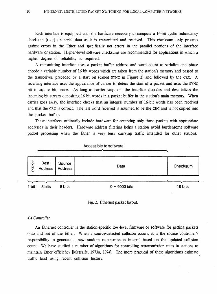
A transmitting interface uses a packet buffer address and word count to serialize and phase
encode a variable number of 16-bit words which are taken from the station's memory and passed to
the transceiver, preceded by a start bit (called SYNC in Figure 2) and followed by the CRC. A
receiving interface uses the appearance of carrier to detect the start of a packet and uses the SYNC
bit to aquire bit phase. As long as carrier stays on, the interface decodes and deserializes the
incoming bit stream depositing 16-bit words in a packet buffer in the station's main memory. When
carrier goes away, the interface checks that an integral number of 16-bit words has been received
and that the eRC is correct. The last word received is assumed to be the eRe and is not copied into
the packet huffer.
These interfaces ordinarily include hardware for accepting only those packets with appropriate
addresses in their headers. Hardware address filtering helps a station avoid burdensome software
packet processing when the Ether is very busy carrying traffic intended for other stations.
Accessible to software
s Dest SourceyChecksumN Address Address
Datac
16 bitso- 4000 bits
___________y~---------.",..J.--~y--~1 bit 8 bits 8 bits
Fig. 2. Ethernet packet layout.
4.4 Controller
An Ethernet controller is the station-specific low-level firmware or software for getting packets
onto and out of the Ether. When a source-detected collision occurs, it is the source controller's
'responsibility to generate a new random retransmission interval based on the updated, collision
count. We have studied a number of algorithms for controlling retransmission rates in stations to- .
maintain Ether efficiency [Metcalfe, 1973a, 1974]. The more practical of the'se algorithms esti.mate
traffic load using recent collision history.
ETHER:\ET: DISTRIBl~TEDPACKET SWITCHING FOR LOCAL COl\1PUTER, NETWORKS 11
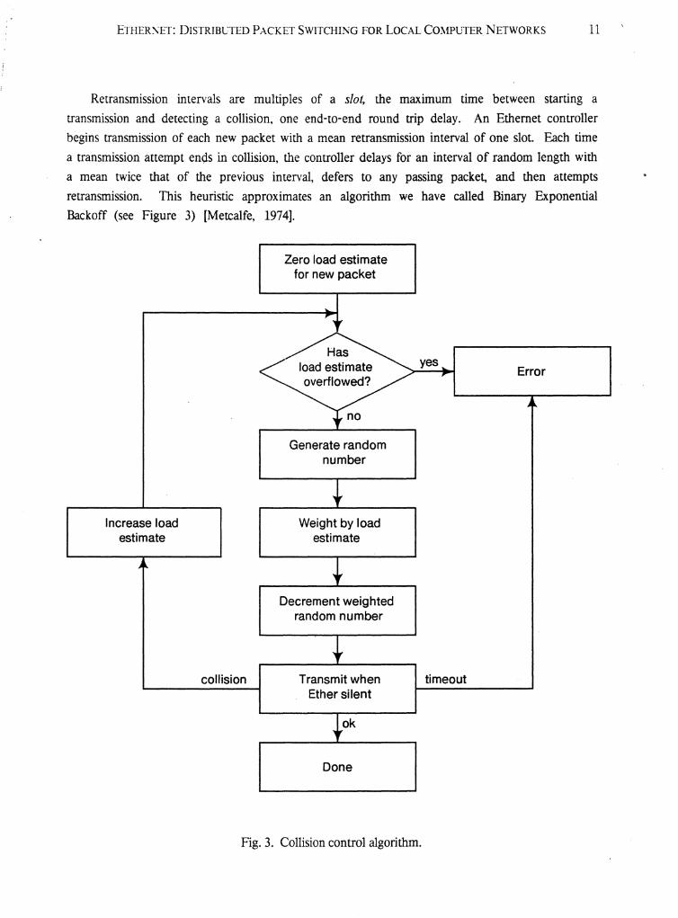
Retransmission intervals are multiples of a slot, the maximum time between starting a
transmission and detecting a collision, one ·end-to-end round trip delay. An Ethernet controller
begins transmission of each new packet with a mean retransmission interval of one slot. Each time
a transmission attempt ends in collision, the controller delays for an interval of random length with
a mean twice that of the previous interval, defers to any passing packet, and then attempts
retransmission. This heuristic approximates an algorithm we have called Binary Exponential
Backoff (see Figure 3) [Metcalfe, 1974].
Zero load estimatefor new packet
Increase loadestimate
collision
Generate randomnumber
Weight by loadestimate
Decrement weightedrandom number
Transmit whenEther silent
ok
Done
yes
timeout
Error
Fig. 3. Collision control algorithm.

12 ETHER~ET: DlSTRIBCTED PACKET SWITCHli\G FOR LOCAL CO~1PUTER NETWORKS
When the network is unloaded and collisions are rare, the mean seldom departs from one and
retransmissions are prompt As the traffic load increases, more collisions are experienced, a backlog
of packets builds up in the stations, retransmission intervals increase, and retransmission traffic
backs off to sustain channel efficiency.
5. Growth
5.1 Signal Cover
One can expand an Ethernet just so far by adding transceivers and Ether. At some point, the
transceivers and Ether will be unable to carry the required signals. The signal cover can be
extended with a simple unbuffered packet repeater. In our experimental Ethernet where, because· of
transceiver simplicity the Ether :annot be branched passively, a simple repeater may joL'l any
number of Ether segments to enrich the topology while extending the signal cover.
We operate an experimental two-segment packet repeater, but hope to avoid relying on them.
In branching the Ether and extending its signal cover, there is a trade-off between using
sophisticated. transceivers and using repeaters. With increase4 power and sensitivity, transceivers
become more expensive and less reliable. The introduction of repeaters into an Ethernet makes the
centrally interconnecting Ether active. The failure of a transceiver will sever the communications of
its owner; the failure of a repeater partitions the Ether severing many communications.
5.2 Traffic Cover
One can expand an Ethernet just so far by adding Ether and packet repeaters. At some point
the Ether will be so busy that additional stations will just divide more finely the already inadequate
bandwidth: The traffic cover can be extended with an unbuffered tra~c-filtering repeater or packet
filter, which passes packets from one Ether segment to another only if the destination station is
located on Ule new segment. A packet filter also extends the signal cover.
5.3 Address Cover
One can expand an Ethernet just so far by adding Ether, repeaters, and traffic filters. At some
point there will be too many stations to be addressed with the Ethernet's 8-bit addresses. The
address cover can be extended with packet gateways and the software addressing conventions they
implement [Cerf, 1974]. Addresses can be expanded in two directions: down into the station by
adding fields to identify destination ports or processes within a station, and up into the internetwork
by adding fields to identify destination stations on remote networks. A gateway also extends the
traffic and signal covers.
ETHER!\ET: DISTRIBLIED,PACKET S\VITCIIING FOR LOCALCO~1PUTER NETWORKS 13
There can be only one repeater or packet filter connecting two Ether segments; a packet
repeated onto a segment ·by multiple repeaters would interfere with itself. However, there ,is no
limit to the number of gateways connecting two segments; a gateway only repeats packets addressed
to itself as an intermediary. Failure of the single repeater connecting two segments partitions the
network; failure of a gateway need not partition the net if there are paths through' other gateways
between the segments.
6. Performance
Here is a simple set of formulas with which to characterize the performance expected of an
Ethernet when it· is heavily loaded. More elaborate analyses and several detailed simulations have
been done, but the following simple model has proven very useful in understanding the Ethernet's
distributed contention scheme, even when it is loaded beyond expectations [Abramson, 1970;
Metcalfe, 1973a, 1973b, 1974; Roberts, 1973; Murthy, 1975].
We develop a simple model of the performance of a loaded Ethernet by examining alternating
Ether time periods. The first, called a transmission interval, is that during which the Ether has been
acquired for a successful packet transmission. The second, called a contention interval, is that
composed of the retransmission slots of Section 4.4, during which stations attempt to acquire control
of the Ether. Because the model's Ethemets are loaded and because stations defer to passing
packets before starting transmission, the slots are synchronized by the tail of the preceding
acquisition interval. A slot will be empty when no station chooses to attempt transmission in it and
it will contain a collision·if more than one station attempts to transmit. When a slot contains only
one attempted transmission, then the Ether has been acquired for the duration of a packet, the
contention interval ends, and a transmission interval begins.
Let P be the number of bits in an Ethernet packet. Let C be the peak capacity in bits per
second, carried on the Ether. Let T be the time in seconds of a slot, the number of seconds it takes
to detect a collision after starting a transmission. Let us assume that there are Q stations
continuously queued to transmit a packet; either the acquiring station has a new packet immediately
after a successful acquisition or another station comes ready. Note that Q also happens to give the
total offered load on the network which for this analysis is always 1 or greater. We assume that a
queued station. attempts to transmit in the current slot with probability l/Q, or delays with
probability 1-(1/Q); this is known to be the optimum statistical decision rule, approximated in
Ethernet stations by means of our load-estimating retransmission control algorithms [Metcalfe,
1973a, 1973b].

14· ETI-IER~ET: DISTRIBLIED PACKET S\\'ITCHING FOR LOCAL COl\1PCTER NETWORKS
6.1 Acquisition Probability
We now compute A, the probability that exactly one station attempts a transmission in a slot
and therefore acquires the Ether. A is Q*(l/Q)*«I-(lIQ»(Q-l»;. there are Q ways in which one
station can choose to transmit . (with probability (IIQ» while Q-l stations choose to wait (with
probability 1-(11Q». Simplifying,
A =(1-(I/Q»(Q-1).
6.2 Waiting Time
We now compute W, the mean number of slots of waiting in a contention interval before a
successful acquisition of the Ether by a station's transmission. The probability of waiting no time at
all is just A, the probability that one· and only one station chooses to transmit in the first slot
fJllowing a tr3~smission. The probabi!ity of waiting 1 slot is A*(I-A); tile probability of waiting i
slots is A*«l-A)i). The mean of this geometric distribution is
w= (I-A)IA.
6.3 Efficiency
We now compute E, that fraction of time the Ether is carrying good packets, the efficiency.
The Ether's time is divided between transmission intervals and contention intervals. A packet
transmission takes PIC seconds. The mean time to acquisition is Ul*T. Therefore, by our simple
model,
E = (P/C)/«PIC)+(UI*n).
Table I presents representative performance figures (Le., E) for our experimental Ethernet with
the indicated packet sizes and number of continuously queued stations. The efficiency figures given
do not account for inevitable reductions due to headers and control packets nor for losses due to
imprecise control of the retransmission parameter IIQ; the former is straightforwardly protoc01
dependent and the latter requires analysis beyond the scope of this paper. Again, we feel that all of
the Ethemets in the table are overloaded; normally loaded Ethemets will usually have a Q ·much
less than 1 and exhibit behavior not covered by this model.
For OUf calculations, we use a C of 3 megabits per second and aT of 16 microseconds. The
slot duration, T,must be long enough to allow a collision to be detected or at least twice the Ether's
round trip time. We limit in software the maximum length of our packets to be near 4000 bits to
keep the latency of network access down and to permit efficient use of station packet buffer storage.

ETHERXET: DISTRIBCTED PACKET S\VITCHING FOR LOCAL CO~1PlJTERNETWORKS 15
Table I"Ethernet Efficiency.
Q P=4096 P=1024 P=512 P=48
1 1.0000 1.0000 1.0000 1.0000
2 0.9884 0.9552 0.9143 0.5000
3 0.9857 0.9447 0.8951 0.4444
4 0.9842 0.9396 0.8862 0.4219
5 0.9834 0.9367 0.8810 0.4096
10 0.9818 0.9310 0.8709 0.3874
32 0.9807 0.9272 0.8642 0.3737
64 0.9805 0.9263 0.8627 0.3708
128 0.9804 0.9259 0.8620 0.3693
256 0.9803 0.9257 0.8616 0.3686
For packets whose size is above 4000 bits, the efficiency· of our experimental Ethernet stays well
above 95 percent. For· packets with. a ,size··· approximating that of a slot, Ethernet· efficiency
approaches lie, the asymptotic efficiency of a. slotted Aloha network [Roberts, 1973].
7. Protocol
There is more to the construction of a viable packet communication system than simply
providing the mechanisms for packet transport. Methods' for error correction, flow control, process
naming, security, and accounting must also be provided through higher level protocols implemented
on top of the Ether control protocol decribed in Sections 3 and 4 above [Ceri: 1974; Crocker, 1972;
Metcalfe, 1973b; Farber, 1975; Rowe, 1975; Walden, 1972]. Ether control includes packet framing,
error detection, addressing and multi-access control; like other line control procedures, Ethernet is
used to support numerous network and multiprocessor architectures [SDLC" 1974; SNA, 1975].
Here isa brief description of one simple error-controlling packet protocol. The EFfP (Ethernet
File Transfer Protocol) is of interest both because it is relatively easy to understand and implement
correctly and because it has dutifully carried many valuable files during the development of more
general and efficient protocols.

16 ETHERNET: DISTRIBL'TED PACKET SWITCHI~G 'FOR LOCAL COMPUTER NETWORKS
7.1 General Terminolog)"
In discussing packet protocols" we 'use the following generally. useful terminology. A packet is
said to have a source and a destination. A flow of data is said to have a sender and a receiver,
recognizing that to support a flow of data some p~ckets (typically acknowledgments) will be sourced
at the receiver and destined for the sender. A connection is said to have a listener and an initiator
and a service is said to have a server and a user. It is very useful to treat these as orthogonal
descriptors of the participants in a communication. Of course, a server is usually a listener and the
source of data-bearing packets is usually the sender.
7.2 EFTP
The first 16 bits of all Ethernet packets contain its interface-interpretable destination and source
station addresses, a byte each, in that order (see Figure 2). By software convention, the second '16
bits of all Ethernet packets cOl1tain_ the packet type.' Different protocols use disjoint sets of packet
types. The EFfP uses 5 packet types: data, ack, abort, end, and endreply. Following the 16-bit type
word of an EFfP packet are 16 bits of sequence number, 16 bits of length, optionally some 16-bit
data words, and finally a 16-bit software checksum word (see Figure 4). The Ethernet's hardware
checksum is present only on the Ether and is not counted at this level of protocol.
Destination Source
Packet Type
Sequence Number
Length (in words)
~~ Data (words)
~h
. Software Checksum
DataPacketsOnly
1-·-(.-.......----- 16 bits -------1_....1
Fig. 4. EFfP packet layout.

ETHER~ET: DISTRIBCTED PACKET SWITCHI~G FOR LOCAL C01\1PUTER NETWORKS" 17
It· should be obvious that little care has been taken to cram certain fields into just the right
number of bits. The ., emphasis here is on simplicity and ease of programming. ' Despite th'is
disclaimer, we do feel that it is more advisable to err on the side of spacious fields; try as you may,
one field or another will always turn out to be too small.
The software checksum word is used to lower the probability of an undetected error. It serves
not only as a backup for the experimental Ethemefs serial hardware 16-bit cyclic redundancy
checksum (in Figure 2), but also for protection against failures in parallel data paths within stations
which are not checked by the CRee The checksum used by the EFfP is a 1's complement add and
cycle over the entire packet, including header and content data. The checksum can be ignored at
the user's peril at either end; the sender may put all l's (an impossible value) into the checksum
word to indicate to the receiver that no checksum was computed.
7.2.1 Data Transfer. The 16-bit words of a file are carried from sending station to receiving station
in data packets consecutively numbered from O. Each .data packet is retransmitted periodically by
the sender until an ack packet with a matching sequence number is returned from the receiver. The
receiver ignores all damaged packets, packets from a station other than the sender, and packets
whose sequence number does not match either the expected one or the one preceding. When a
packet has the expected sequence numbe.r, the packet is acked, its data is accepted as part of the
file, and the sequence number is incremented. When a packet arrives with a sequence number one
less than that. expected, it is .acknowledged and discarded; the presumption is that its ack was lost
and needs retransmission (Metcalfe, 1973b).
7.2.2 End. When all the data has been transmitted, an end packet is sent with the next consecutive
sequence number and then the sender waits for a matching endreply. Having accepted an end
packet in sequence, the data receiver responds with a matching endreply and then dallys for some
reasonably long period of time (10 seconds). Upon getting the endreply, the sending station
transmits an echoing endreply and is free to go off with the assurance that the file has been
transferred successfully. The dallying receiver then gets the echoed endreply and it too goes off
assured.
The comparatively complex end-dally sequence is intended to make it practically certain that
the sender and receiver ofa file will agree on whether the file has been transmitted correctly. If the
end packet is lost, the data sender simply retransmits it as it would any packet with an overdue
acknowledgement. If the endreply from the data receiver is lost, the data sender will time out in
the same way and retransmit the end packet which will in tum be acknowledged by the dallying
receiver. If the echoed endreply is lost, the dallying receiver will be inconvenienced having to wait
for it, but when it has timed out, the receiver can nevertheless be assured of suc-cessful transfer of
the file because the end packet has bee-n received.
.At any time during all of this, either side is free to decide communication has failed and just
give up; it is considered polite to send an abort packet to end the communication promptly In the

, 18 ETHERNET: DISTRIBUTED PACKET SWITCHING FOR LOCAL COMPUTER NET\VORKS
event -of: '. say, a user-initiated abort or a file system error.
7.23 "EFTP Shortcomings. The EFfP has been very useful, but its shortcomings are many_ First,
the protocol provides only for file ·transfer from station to station in a single network and
specifically not from process· to process within stations either on the .same network or through a
gateway. Seconq, process rendezvous is degenerate in that there are no mechanisms for finding
processes by name or. for convenient handling of multiple users by a single server. Third, there is
no real flow control. If data arrives at a receiver unable to accept it into its buffers, the data can
simply be thrown away with complete assurance that it will be retransmitted eventually. There is no
\yay for a receiver to quench the flow of such wasted transmissions or to expedite retransmission~
Fourth, data is transmitted in integral numbers of 16-bit words belonging to unnamed files and thus
the EFfP is either terribly restrictive or demands some nested file transfer formats internal to its data
words. And fifth, functional generality is lost because the receiver is also the listener and server.
8. Conclusion
Our experience with an operating Ethernet leads us to conclude that our emphasis on
distributed control was well placed. By keeping the shared components of the communication
system to a minimum and passive, we have achieved a very high level of reliability. Installation,and
maintenance of our experimental Ethernet has been more than satisfactory. The flexibility of
station interconnection provided by' broadcast packet switching has encouraged the development of
numerous computer networking and multiprocessing applications.
9. Acknowledgements
Our colleagues at the Xerox Palo Alto Research Center, especi~ly Tat C. Lam, Butler W.
Lampson, John F. Shoch, and Charles P. Thacker, have contributed in many ways to the evolution
of Ethernet ideas and to the construction. of the experimental system without which ,such ideas
would be just so much speculation.
ETHER:\ET: I)ISTRIBCTED PA~CKET S'VITCHING FOR LOCAL COMPUTER NETWORKS 19
10. References
[Abramson, 1970]N. Abramson, "The AlohaSystem~', AFIPS Conference Proceedings, voL 37, Fall 1970.
-- [Abramson, 1975]N. Abramson, F.F. Kuo, Computer-Comlnunication Networks, Prentice-Hall, 1975.
[Ashenhurst, 1975]R.L. Ashenhurst, R.H. Vonderohe, "A Hierarchical Network", Datamation, February 1975.
[Baran, 1964]P. Baran, On Distributed Comnlunications, Rand Corporation Memo RM-3420-PR, August1964.
[Barnes, 1968]G.H. Barnes, R.M. Brown, M. Kato, D.J. Kuck, D.L. Slotnick, R.A. Stokes, "The Illiac IVComputer", IEEE Transactions, C-17, vol. 8, August 1968.
[Binder, 1975]R. Binder, N. Abramson, F. Kuo, A. Okinaka, D. Wax, "Aloha Packet Broadcasting-ARetrospect", Proceedings of the National Computer Conference, May 1975.
[Cerf, 1974]V.G. Cert: R.E. Kahn, "A Protocol for Packet Network Intercommunication", IEEE
Transactions on Conlmunications, vol. cOM-22, no. 5, May 1974.
[Computer, 1974a]"The Shrinking World: Computer Networks and Communications", Computer, IEEE ComputerSociety, February 1974.
[Computer, 1974b]"Distributed-Function Computer Architectures", Computer, IEEE Computer Society, March1974.
[Crocker, 1972]S.D. Crocker, J.F. Heafner, R.M. Metcalfe, and I.B. Postel, "Function-Orie·nted Protocols forthe ARPA Computer Network", AFIPS Conference Proceedings, vol. 40, May 1972. Reprinted inAdvances in COlnputer Communications, edited by W.W. Chu, Artech House Inc., 1974.Reprinted in Computer Communications, edited by P.E. Green and R.W. Lucky, IEEE press,1975.
[Crowther, 1975]W.R. Crowther, F.E. Heart, A.A. McKenzie, J.M. McQuillan, and D.C. Walden, "Issues inPacket-Switching Network Design", Proceedings of the National Computer Conference, May1975.
i
[Farber, 1973] I
DJ. Farber, et ai, "The Distributed Computing System", ProceediJgs of the 7th Annual IEEE
Computer Society International Conference, February 1973. I[Farber, 1975)
D.J. Farber, "A Ring Network", Datamation, February 1975.

20 ETHERi'\ET: DISTRIBUTED PACKET SWITCHING FOR LOCAL COMP1JTER NETWORKS
[Fraser, 1975]A.G. Fraser, itA Virtual Channel Network", Datamalion, Febru~ 1975.
(Heart, 1970]F.E. Hean, R.E. Kahn, S.M. Ornstein, W.R. Crowther, D.C. Walden, "The Interface MessageProcessor for the Arpa Computer Network", AFIPS Conference Proceedings, vol. 36, May 1970.
[HeaIt 1973]F.E. Heart, S.M. Ornstein, W.R. Crowther, and W.B. Barker, "A New MinicomputerMultiprocessor for the Arpa Network", DIPS Conference Proceedings, vol. 42, June '1973.Reprinted in Advances in Computer Communications, edited by W.W. Chu, Artech House Inc.,1974.
[Kahn, 1975]R.R. Kahn, "The Organization of Computer Resources into a Packet Radio. Network",Proceedings of the National Computer Conference, May 1975.
[Metcalfe, 1972a]R.M. Metcalfe, "Strategies for Interprocess Communication in a Distributed ComputingSystem", Proceedings of the Symposium on Compute,.Communications Networks and Teletraffic,Polytechnic Press, New York, 1972.
[Metcalfe, 1972b]R.M. Metcalfe, "Strategies for Operating Systems in Computer Networks", Proceedings of theACM National Conference, August 1972.
[Metcalfe, 1973a]R.M. Metcalfe, "Steady-State Analysis of a Slotted and Controlled Aloha System withBlocking", Proceedings of the Sixth Hawaii Conference on System Sciences, January 1973.Reprinted in the Sigcomm Review, January 1975.
[Metcalfe, 1973b]R.M. Metcalfe, Packet Communication, Harvard PhD Thesis, Massachusetts Institute ofTechnology Project Mac TR-114, December 1973.
[Metcalfe, 1974]R.M. Metcalfe, "Distributed Algorithms for a Broadcast Queue", talk given at StanfordUniversity in November 1974 and at the University of California at Berkeley in Febraury 1975,paper in preparation.
[Murthy, 1975]P. Murthy, "Analysis of a Carrier-Sense Random-Access System with Random Packet Lengths",Aloha System Technical Report B75-17, University of Hawaii, May 1975.
[Ornstein, 1975]S.M. Ornstein, W.R. Crowther, M.F. Kraley, R.D. Bressler, A. Michel, and F.E. Heart,"Pluribus-A Reliable Multiprocessor", Proceedings of the National Computer Conference, May1975.
[Retz, 1975JD.L. Retz, "Operating·System Design Considerations for the Packet Switching Environment",Proceedings of the National Computer Conference, May 1975.

ETHERNET: DISTRIBD'TED PACKET SWITCHING FOR LOCAL COMPUTER NETWORKS 21
[Robens, 1970]L. Roberts, B. Wessler, "Computer Network Development to Achieve Resource Sharing", AFIPSConference Proceedings, vol. 36, May 1970.
[Roberts, 1973]L.G. Roberts, "Capture Effects on Aloha Channels", Proceedings of the Sixth HawaiiConference on S}'stem Sciences, January 1973.
[Rowe, 1975]L.A. Rowe, "The Distributed Computing Operating System", Technical Report Number 66,Department of Information and Computer Science, University of California, Irvine, June 1975.
[Rustin, 1972]R. Rustin, Editor, Computer Networks, Proceedings of the Courant Computer ScienceSymposium 3, December 1970, Prentice-Hall Series in Automatic Computation, 1972.
[sDLe, 1974]IBM Synchronous Data Link Control-General Information, IBM Systems De,velopment Division,Publications Center, Department E01, P.O. Box 12195, Research Triangle Park, North Carolina
.t 27709, 1974.
[SNA, 1975]IBM System Network Architectur~General Infromation, IBM Systems Development Division,Publications Center, Department EOI, P.O. Box 12195, Research Triangle Park, North Carolina27709, 1975.
[Thomas, 1973]R.H. Thomas, "A Resource Sharing Executive for the Arpanet", AFIPS Conference Proceedings,October 1973.
[Thornton, 1970]J.E. Thornton, Design of a Computer: the Control Data 6600, Scott Foresman and Company,1970.
[Walden, 1972]D.C. Walden, "A System for Interprocess Communication in' a Resource Sharing ComputerNetwork", Communications of the ACM, vol. 15, no. 4, April 1972.
[Willard, 1973]D.O. Willard, "Mitrix: A Sophisticated Digital Cable Communications System", Proceedings ofthe National Telecommunications Conference, November 1973.
[Wult: 1972]W. Wulf, R. Levin, "C.mmp-A Multi-~ini-Processor", AFIPS Conference Proceedings, Fall~.972.