
ET ISO 16933: Glass in building -- Explosion-resistant...
27
ET ISO 16933 (2007) (English): Glass in building -- Explosion-resistant security glazing -- Test and classification for arena air-blast loading
Transcript of ET ISO 16933: Glass in building -- Explosion-resistant...

Federal DemocraticRepublic of Ethiopia
≠ EDICT OF GOVERNMENT ±In order to promote public education and public safety, equal justice for all, a better informed citizenry, the rule of law, world trade and world peace, this legal document is hereby made available on a noncommercial basis, as it is the right of all humans to know and speak the laws that govern them.
ET ISO 16933 (2007) (English): Glassin building -- Explosion-resistantsecurity glazing -- Test andclassification for arena air-blastloading


ES ISO :2012
STANDARD
Glass in building �— Explosion-resistant security glazing �— Test and classification for arena air-blast loading
Identical with ISO 16933:2007
User
User
User
User
User

Foreword
This Ethiopian Standard has been prepared under the direction of the Technical Committee for
(TC ) and published by the Ethiopian Standards Agency (ESA). The standard is identical with ISO
published by tandards ( ). For the purpose of this Ethiopian Standard , the adopted text shall be modified as follows. The phrase “International Standard” shall be read as “Ethiopian Standard”; and A full stop (.) shall substitute comma (,) as decimal marker.

STANDARD SO 16933:20 (E)
1
Glass in building �— Explosion-resistant security glazing �— Test and classification for arena air-blast loading
1 Scope
This International Standard provides a structured procedure to determine the air-blast resistance of glazing and sets forth the required apparatus, procedures, specimens, other requirements and guidelines for conducting arena air-blast tests of security glazing. Seven standard blasts simulating vehicle bombs and seven standard blasts simulating smaller satchel bombs that can be used to classify glazing performance are incorporated in this International Standard and cover a broad range of blast parameters.
Security glazing, including that fabricated from glass, plastic glazing sheet material, glass-clad plastics, laminated glass, insulated glass, glass/plastic glazing materials and film-backed glass, can be tested and classified in a standard frame or tested but not classified in frames provided with the glazing.
Classification and ratings are assigned based on the performance of glazing loaded by air-blast pressures and impulses, and are specific to the blast characteristics under which the test takes place. Glazing that has received an air-blast classification and rating is suitable for use in blast-resistant applications only for blasts of comparable characteristics and only if installed in a properly designed frame. Design based on knowledge of the air-blast resistance reduces the risk of personal injury.
2 Normative references
The following referenced documents are indispensable for the application of this document. For dated references, only the edition cited applies. For undated references, the latest edition of the referenced document (including any amendments) applies.
ISO 48:1994, Rubber, vulcanized or thermoplastic �— Determination of hardness (hardness between 10 IRHD and 100 IRHD)
3 Terms and definitions
For the purposes of this document, the following terms and definitions apply.
3.1 air-blast pressure history description of the pressure of a reflected or free-field air blast, as measured at a point on the surface and consisting of two separate phases:
positive phase, which is characterized by a nearly instantaneous rise to a maximum pressure followed by an exponential decay to ambient pressure;
negative phase, immediately following the positive phase, during which the pressure decreases below ambient for a period of time before returning to ambient
3.2 ambient temperature temperature at which the test is conducted

ISO 16933:20 (E)
2
3.3 blast mat steel or concrete pad upon or above which a high explosive may be detonated to reduce the incidence of ejecta
3.4 breach any perforation or opening through the test specimen or between the test specimen and the support frame, evident after the test, through which a 10 mm diameter rigid bar can be gently passed without force
NOTE An opening may be caused by the glazing sheet infill pulling away from the rebate sufficiently to result in a visible gap that exposes the edge of the sheet.
3.5 cartridge paper thick white paper for pencil and ink drawings, typically about 130 g/m2
3.6 free-field air-blast pressure blast pressure acting at any given point in the free field, where there is no structure or other object disturbing the blast wave propagation
NOTE Also referred to as incident pressure, being the pressure measured on surfaces incidental to or parallel with the direction of travel of the blast front.
3.7 fragment any particle with a united dimension of 25 mm (1 in) or greater
NOTE The united dimension of a glass particle is determined by adding its width, length and thickness. Glazing dust, slivers and all other smaller particles are not accounted as fragments.
3.8 glazing glass or plastics glazing sheet material, including glass/plastic combinations
3.9 indents any detectable deformation of the foil or cartridge paper surface of the witness panel caused by impact of any material as a result of the blast
3.10 peak-positive air-blast pressure maximum measured positive phase air-blast pressure
NOTE If the measured pressure-time trace has sharp irregularities, the trace should be smoothed to produce a pressure-time trace that closely matches the mean path of the recorded trace. The peak pressure, Pmax, of relevance is the resulting smoothed value.
3.11 perforations any holes in the foil, cartridge paper or plain surface of the witness panel caused by impact of any material as a result of the blast
3.12 positive phase impulse integral of the measured positive phase air-blast pressure history
3.13 reaction structure all elements of the structure designed to support the test frame or alternative means for holding the glazing to be tested

ISO 16933:20 (E)
3
3.14 reflected air-blast pressure pressure increase that a surface, oriented other than parallel to the line from the detonation point to the surface, experiences due to the detonation of a high-explosive charge
3.15 standoff distance perpendicular distance from the plane of the front surface of the glazing to the centre of the explosive charge or from the centre of the glazing if not perpendicular to the explosive
3.16 test frame reaction structure, to which are fastened all elements that are used to directly support the glazing during classification of the glazing
3.17 witness panel panel of deformable material positioned behind the test specimen in order to register the incidence of material forcibly detached from the test specimen during test
NOTE The composition and location of the witness panel is described in 6.6.
4 Hazard rating
A hazard rating is applied to glazing based on its performance under the blast conditions chosen for the test. The rating is specific only to those blast conditions.
5 Test specimens
5.1 Number of test specimens
For the purpose of classifying glazing a minimum of three test specimens, each (1 100 5 mm) mm (900 5) mm shall be tested at a given level of air blast, defined in terms of peak positive air-blast pressure and positive phase impulse. One additional specimen shall be provided for pre-test measurements. Glazing of other sizes may be tested if the manufacturer supplies framed glazing or frame specifications. As such non-standard glazing assemblies may only be tested but not classified in accordance with this standard, the number of test specimens will be as agreed prior to test.
5.2 Multiple specimens
The air-blast resistance capacity of glazing does not imply that a particular specimen resists the specific air blast for which it is rated with a probability of 1,0. However, the probability that a single glazing or glazing system will resist the specific air blast at the particular level for which it is rated increases proportionally with the number of test specimens that successfully resist that air blast at that level. The protection afforded against a blast by a single item of glazing depends not only upon the glazing but also upon the manner in which it is attached to the structure in which it is mounted.
5.3 Handling and storage
The test specimens shall be handled and stored in compliance with the manufacturer�’s instructions.
5.4 Marking
Each specimen shall be marked with the manufacturer�’s model and serial numbers and the date of manufacture. The attack side is intended to be oriented towards the explosive charge and shall be marked by

ISO 16933:20 (E)
4
the manufacturer to assure proper installation in the test frame. A number shall be assigned to each test specimen and shall be marked accordingly.
5.5 Measurements
Thickness measurements of the glazing material shall be made at each corner, 25 mm from each edge, and recorded. If the specimens are supplied already mounted in a frame, one of the specimens shall be selected at random and inspected for details. Measurements shall include the edge dimensions of the frame and the glazing material, the cross-sectional dimensions of the frame and thickness measurements of the glazing material. The frame and glazing materials shall be verified to comply with the manufacturer�’s specifications. Measurements and records shall be made of the bolts, screws or other devices used for fixing the test frame or other glazing support system to the reaction structure.
5.6 Photography
Prior to the test, a photographic record that adequately portrays the test specimens, the test frame and the test configuration shall be made. This photographic record shall consist of still photographs and may include motion pictures or video.
6 Facilities and equipment preparation
6.1 Test facility
The test facility shall consist of an open-air arena located on clear and level terrain. The test facility shall be situated, and of sufficient size, to safely accommodate detonation of the amount of explosive required to provide the desired peak positive air-blast pressure and positive phase impulse. Potential environmental impact issues shall be analyzed and resolved prior to testing. Unless otherwise specified, testing shall be conducted at ambient temperature as defined in 3.2 and Clause 8.
6.2 High-explosive charge
A high-explosive charge shall be used to generate the desired peak positive air-blast pressure and positive phase impulse on the test specimens. The explosive composition, shape, mass, height and location shall be adjusted to meet these required parameters within the tolerances allowed.
6.3 Blast mat
If there is a possibility of crater ejecta interfering with the test, the high-explosive charge shall be placed on a blast mat. The decision to use a blast mat, its size and thickness shall be at the discretion of the test director.
6.4 Test frame and reaction structure
For classifying the glazing, the following test frame and reaction structure requirements shall apply.
a) Test specimen(s), each with a vision size of 1 000 mm 800 mm, shall be mounted on a test frame, along the full length of all four edges. The test frame and reaction structure shall be capable of resisting the air blast with deflections that do not exceed L/360, where L denotes the dimension of a test frame or reaction structure member measured between the lines of support.
b) The test frame shall be fixed securely in a vertical position to the reaction structure. The test frame shall be provided with clamping plates to hold each glazing in position and means for producing uniform clamping of the glazing.
Bolt spacing of not more than 100 mm is recommended around the perimeter of each glazing.
DRAFT

ISO 16933:20 (E)
5
c) The test specimens shall be mounted in a manner that meets the following requirements.
Mount standard-sized test specimens so that the bottom edge is between 0,5 m and 1,0 m above the floor of the witness area.
Each test specimen shall have an edge capture of not less than 45 mm on all edges.
Each test specimen shall be separated from the test frame and the clamping plate by continuous rubber strips (4 0,5) mm thick, (50 5) mm wide and of hardness (50 10) IRHD in accordance with ISO 48:1994.
At the bottom of the rebate, each test specimen shall be seated on rubber strips (4 0,5) mm thick, of hardness (50 10) IRHD in accordance with ISO 48:1994 and of width equal to the full thickness of the test piece.
All four edges of each test specimen shall be uniformly clamped with a clamping pressure of (140 30) kN/m2.
NOTE The clamping pressure can have a significant effect on the test results.
d) If the glazing is supplied with its own unique frame or in a fenestration assembly, it shall be attached to the reaction structure as directed by the manufacturer and in a manner that closely models the manner in which it will be mounted in the field. Non-standard test specimens may be mounted at heights appropriate to the manner in which they will be mounted in the field.
e) All test specimens and witness panels shall be completely enclosed in a structure designed to prevent air-blast pressure from wrapping behind the test specimens.
f) Unless otherwise specified, each test frame shall be placed so that the test specimens are oriented perpendicular to a line from the detonation point to the centre of the test frame in order that they experience reflected pressures. The above directions assume such an orientation with the test specimen mounted vertically. Any other orientation shall be agreed with the test sponsor in advance of testing and shall be recorded as required in 9.1c) as it can affect failure modes and hazard ratings.
g) The classification blast values are based upon tests using reaction structures (test cubicles) having face dimensions approximately 3 m 3 m as described in Annex C. If the reaction structure is oriented perpendicular to the line of the detonation point, the face of the reaction structure should not be less than 2,4 m wide 2,4 m high. This is in order to avoid excessive reductions in reflected impulse that arise owing to the effects of blast clearing from the edges of small targets. For further information on assessing the blast relative to the size of the reaction structure, tests, criteria and effects on glazing, see Reference [8].
6.5 Instrumentation
6.5.1 Pressure transducers
A minimum of three air-blast pressure transducers shall be mounted on the exterior of each reaction structure. The air-blast pressure transducers shall be flush with the surface of the reaction structure on the air-blast side. The transducers shall be located such that the pressure and impulse in the centre of each test specimen can be computed. As an alternative, the pressure transducers may be installed on a transducer panel of the same size as the test frame and located and oriented in the same manner with respect to the charge as the test frame.
All pressure transducers shall be capable of defining the anticipated air-blast pressure history within the linear range of the transducer. Each transducer shall have a rise/response time and resolution sufficient to capture the complete event. Limited low-frequency response transducers shall have a discharge-time constant equal to approximately 30 times to 50 times the initial positive phase duration of the anticipated air-blast pressure

ISO 16933:20 (E)
6
history. Calibration records shall be maintained that demonstrate the equipment can measure pressure within an accuracy of 5 %.
At least one free-field pressure transducer shall be used in each test. The free-field pressure transducer shall be located at least 5 m or the width of the reaction structure, whichever is greater, from any reaction structure and at the same horizontal distance from the high-explosive charge as the centre of the glazing.
Optionally, appropriate pressure transducers may also be located within the enclosure behind the glazing to measure the pressure within the protected area during the blast. All pressure transducers shall be attached to the data-acquisition system and tested prior to the blast to verify proper operation.
All pressure-time readings shall be examined to derive the peak pressure values from the smoothed path of the measured trace. The individual peak pressure values subsequently recorded shall in each case be that adjusted by smoothing as necessary to eliminate sharp spikes arising from recording and instrumentation irregularities. The value derived from several of these individual, adjusted peak pressures for comparison with the classification criteria is referred to as the �“mean peak air-blast pressure", as in Clause 8 and Tables 2 and 3. Where a transducer panel is used, this is simply the �“mean�” or the �“average�” of the adjusted peak pressures recorded by at least three transducers near the simulated centre of the target. Where blast measurements have been taken from transducers around the edge of the test specimens, it can be necessary to derive the �“mean peak pressure�” determined for the centre by more complex computation. For further information, see Annexes A and B.
6.5.2 Data-acquisition system
The data-acquisition system shall consist of either an analog or a digital recording system with a sufficient number of channels to accommodate all pressure transducers and any other electronic measuring devices. The data-acquisition system shall operate at a minimum sampling rate of 100 000 samples per second (a sampling interval of 0,01 ms) with a rise-time sensitivity response to peak pressure of 10 µs. A higher sampling rate is recommended for the satchel tests. The system shall be capable of recording reliably the peak positive air-blast pressure and the complete pressure-time trace through the negative phase loading as well. The data-acquisition system shall also incorporate filters to exclude alias frequency effects from the data.
6.5.3 Photographic equipment
Adequate photographic equipment shall be available to document the test.
6.5.4 Temperature-measuring device
A temperature-measuring device shall be used to accurately measure glazing-surface temperature and air temperature no more than 30 min prior to the blast.
6.6 Witness panels
A witness panel (3.17) shall be mounted behind each test specimen and inside the air-blast-resistant enclosure, parallel to the plane of the test specimen. Unless otherwise specified, the witness panel shall be placed (3 0,15) m behind the test specimen. The witness panel shall cover the full area projected behind the test specimen and extend down to the floor of the witness area. The witness panel shall have a width at least that of the minimum permitted reaction structure defined in 6.4, or the width of the test specimen if greater, and a height extending from the level of the collecting mat to 200 mm above the top of the test specimen, or the ceiling of the reaction structure if less.
The witness panel shall consist of sheets of non-ductile, foam insulation board, of material equivalent to extruded polystyrene, polyisocyanurate or urethane, of density (30 5) kg/m3. The board shall be in one or two layers of combined thickness at least 35 mm, mounted in a frame capable of remaining in place even if forcibly impacted by failed pieces of the test specimen. In order to aid recording of the damage and to reduce waste, the board may contain a removable face layer at least 12 mm thick and the witness panel may be

ISO 16933:20 (E)
7
faced with contiguous sheets of aluminium foil1) of thickness not more than 0,025 mm or cartridge paper of weight between 100 g/m2 and 150 g/m2. The foil or cartridge paper surface shall be placed toward the window glazing. To accommodate high-speed photography, a hole no greater than 150 mm 150 mm may be made in the top or bottom corner of the witness panel within an area bounded by one third of the height and width of the panel.
7 Test procedure
7.1 Safety
The range safety officer, or the test director when acting as the range safety officer, is responsible for range safety and procedures. When the test specimens have been mounted on test frames and the high explosives has been placed and is ready to be armed, the area shall be cleared of all non-essential personnel. The high explosive shall then be armed in a manner to maximize safety of personnel in the event of accidental discharge of the explosive during the arming procedure. After the high explosive is armed and all personnel are at a safe distance from the explosive, the explosion shall be triggered.
7.2 Initial inspection
When the blast area is safe to enter, an initial inspection of the test specimens shall be made. The apparent condition of the test specimens shall be recorded. The length and location of any openings in the test specimens and pullout of the glazing from the test frame shall be measured and recorded. The location and description of all parts of the specimen shall be recorded, whether retained in the frame or fallen inside or outside, with identification of inner and outer leaves of glass where appropriate.
Photographs of the test specimens shall be taken before beginning removal of test specimens.
7.3 Glazing and witness-panel inspection
The side of the glazing located away from the blast (inside the enclosure) shall be examined. It shall be determined and noted whether or not any breakage or rupture of the inside surface has occurred. The witness panels shall be carefully inspected for the presence of perforations and indents resulting from the blast. If present, the location of perforations and indents shall be documented, with their height above the floor of the witness area recorded.
7.4 Hazard rating
The hazard rating of the glazing or glazing system shall be in accordance with the rating criteria definitions as given in Table 1 and Figure 1. The hazard rating that glazing or glazing systems receive is based upon the severity of fragments generated during an air-blast test. The fragment severity is determined based upon the number, size, effects and location of fragments that lie at, or behind, the original location observed during post-test data gathering. Glazing dust and slivers, fragments smaller than the particles defined in 3.7 and their effects are not taken into account for the ratings. For rating purposes only, the minimum area of the witness panel defined in 6.6 shall be considered and no account shall be taken of perforations and indents of size less than 3 mm in any direction (width, length and depth) or caused by particles classed as smaller than fragments. Examples of minimum sizes of glass particles classed as fragments are provided in Annex D (informative).
Fragments that shall be considered in rating the glazing or glazing system include those generated by the glazing and any other parts of the glazing system not considered to be part of the test facility. For hazard ratings B and C, parts of the outer leaves may be projected any distance outwards from the attack face towards the blast source. For hazard ratings D, E and F, any parts of the glazing or frame may be projected
1) R-Matte® Plus-3 (manufactured by Rmax, Inc., 13524 Welch Road, Dallas, Texas 75244-5291, USA) is an example of a suitable product available commercially. This information is given for the convenience of users of ISO 16933 and does not constitute an endorsement by ISO of this product.

ISO 16933:20 (E)
8
any distance outwards from the attack face towards the blast source. See 6.1 for a description of the test facility.
Table 1 �— Hazard-rating criteria for arena tests
Hazard rating
Hazard-rating description Definition
A No break The glazing is observed not to fracture and there is no visible damage to the glazing system.
B No hazard The glazing is observed to fracture but the inner, rear face leaf is fully retained in the facility test frame or glazing system frame with no breach and no material is lost from the interior surface. Outer leaves from the attack face may be sacrificed and may fall or be projected out.
C Minimal hazard The glazing is observed to fracture. Outer leaves from the attack face may be sacrificed and may fall or be projected out. The inner, rear face leaf shall be substantially retained, with the total length of tears plus the total length of pullout from the edge of the frame less than 50 % of the glazing sight perimeter.
Also, there are no more than three rateable perforations or indents anywhere in the witness panel and any fragments on the floor between 1 m and 3 m from the interior face of the specimen have a sum total united dimension of 250 mm or less. Glazing dust and slivers are not accounted for in the hazard rating.
If by design intent there is more than 50 % pullout but the glazing remains firmly anchored by purpose-designed fittings, a rating of C (minimal hazard) may be awarded, provided that the other fragment limitations are met. The survival condition and anchoring provisions shall be described in the test report.
D Very low hazard The glazing is observed to fracture and significant parts are located no further than 1 m behind the original location of the rear face. Parts be projected any distance from the attack face towards the blast source.
Also, there are no more than three rateable perforations or indents anywhere in the witness panel, and any fragments on the floor between 1 m and 3 m from the interior face of the specimen have a sum total united dimension of 250 mm or less. Glazing dust and slivers are not accounted for in the rating.
E Low hazard The glazing is observed to fracture, and glazing fragments or the whole of the glazing fall between 1 m and 3 m behind the interior face of the specimen and not more than 0,5 m above the floor at the vertical witness panel.
Also, there are 10 or fewer rateable perforations in the area of the vertical witness panel higher than 0,5 m above the floor and none of the perforations penetrate more than 12 mm.
F High hazard Glazing is observed to fracture and there are more than 10 rateable perforations in the area of the vertical witness panel higher than 0,5 m above the floor, or there are one or more perforations in the same witness panel area with fragment penetration more than 12 mm.

ISO 16933:20 (E)
9
Dimensions in centimetres
Key
1 window A to F hazard ratings: 2 witness panel A no break 3 blast B no hazard 4 very low hazard threshold C minimum hazard 5 low-hazard threshold D very low hazard 6 high-hazard threshold E low hazard F high hazard
Figure 1 �— Cross-section through witness area for arena test
8 Classification criteria
Two sets of blast classification criteria are included in this International Standard. The first is intended for use with glazing designed to protect against vehicle bombs and is based on 100 kg TNT (trinitrotoluene) equivalent blasts. The second is intended for use with glazing designed to protect against smaller hand-carried satchel bombs.
An illustration of the calculation of tolerance from actual blasts is given in Clause B.3. Note that the allowable deviations of either impulse pressure shall not be less than 10 % in the case of hand-carried satchel bombs rather than the 15 % allowed for vehicle bombs as shown in the example.
When glazing is to be classified, ambient temperature shall be (22 17) °C.
8.1 Vehicle bombs
In order to classify the explosion-resistance of glazing intended to resist vehicle bombs according to this International Standard, seven standard blasts are defined in Table 2. Mean peak air-blast pressure and mean positive phase impulse values computed from recordings by the air-blast transducers mounted as defined in 6.5.1 are subject to the test conditions and tolerances as given in 8.1.1.

ISO 16933:20 (E)
10
The glazing classification includes the hazard rating achieved by the glazing as a result of the blast as well as the specific blast parameters as listed in Table 2. For classification purposes, glazing shall be mounted in the frame defined in 6.4.
Nominal charge size and nominal standoff distances capable of giving the required peak pressure and impulse values under certain conditions and when in the reflected orientation are included in Clause C.1.
Table 2 �— Classification criteria �— Vehicle bombs
Classification codea Mean peak air-blast pressure
kPa
Mean positive phase impulse
kPa-ms
EXV45(X) 30 180
EXV33(X) 50 250
EXV25(X) 80 380
EXV19(X) 140 600
EXV15(X) 250 850
EXV12(X) 450 1 200
EXV10(X) 800 1 600
a In the classification code, the letters, i.e. �“EXV�” refer to the type, i.e. a vehicle bomb; numbers denote a nominal standoff distance, expressed in meters, when a charge of 100 kg TNT equivalent is placed at a point perpendicular to the surface of the test specimen when mounted in a reaction structure (test cubicle) of face size about 3 m x 3 m and (X) denotes the hazard rating received during the test. For example, classification code EXV25(C) applies to a test in which a standard blast having peak air-blast pressure of 80 kPa and positive phase impulse of 380 kPa-ms resulted in damage to the glazing resulting in hazard rating C.
8.1.1 Test conditions and tolerances for vehicle bombs
The blast values achieved in a test are influenced by factors such as the charge composition, charge location, TNT equivalency and mass, ground conditions, altitude and the size and orientation of the test frame and test specimen. It is the responsibility of the test director to set up the test in order to impose the required blast values on the surface of the test specimen within the tolerances as determined by the following steps on valid measurements.
a) Determine the percentage variation of each measured or computed pressure and impulse reading from the classification pressure and impulse.
b) Calculate the average percentage variation for all the readings for each parameter, i.e. pressure and impulse independently.
c) Calculate the overall average percentage variation for all the readings for both parameters, i.e. pressure and impulse combined.
d) Verify that the results are within the following tolerances.
a) For each parameter, i.e. pressure or impulse, independently, the average percentage variation shall be not less than 15 %,
b) For both parameters, i.e. pressure and impulse combined as in c) above, the overall average variation shall be not less than zero.

ISO 16933:20 (E)
11
8.2 Hand-carried satchel bombs
In order to classify the explosion-resistance of glazing intended to resist hand-carried satchel bombs in accordance with this International Standard, seven standard blasts are defined in Table 3. Mean peak air-blast pressure and mean positive-phase impulse values, computed from recordings by the air-blast transducers mounted as defined in 6.5.1, are subject to the test conditions and tolerances of specified in 8.2.1.
Nominal charge size and nominal standoff distances capable of giving the required peak pressure and impulse values under certain conditions are included in Clause C.2.
Table 3 �— Classification criteria �— Hand-carried satchel bombs
Classification codea Mean peak air-blast pressure
kPa
Mean positive phase impulse
kPa-ms
SB1(X) 70 150
SB2(X) 110 200
SB3(X) 250 300
SB4(X) 800 500
SB5(X) 700 700
SB6(X) 1600 1000
SB7(X) 2800 1500
a In the classification code the letters, i.e. �“SB�”, refer to the type, i.e. a hand-carried satchel bomb, the number designates the standard blast and (X) denotes the hazard rating received during the test. For example, classification SB4(C) applies to a test in which a standard blast having peak air-blast pressure of 800 kPa and positive phase impulse of 500 kPa-ms resulted in damage to the glazing resulting in hazard rating C.
8.2.1 Test conditions and tolerances for hand-carried satchel bombs
The blast values achieved in a test are influenced by factors such as the charge composition, charge location, TNT equivalency and mass, ground conditions, altitude and the size and orientation of the test frame and test specimen. It is the responsibility of the test director to set up the test in order to impose the required blast values on the surface of the test specimen within the tolerances as determined by the following steps on valid measurements.
a) Determine the percentage variation of each measured or computed pressure and impulse reading from the classification criteria.
b) Calculate the average percentage variation for all the readings for each parameter, i.e. pressure and impulse independently.
c) Calculate the overall average percentage variation for all the readings for both parameters, i.e. pressure and impulse combined.
d) Verify that the results are within the following tolerances.
The mean percentage variation for the readings for either of the parameters, i.e. pressure or impulse, independently, shall not be less than �– 10 %.
The overall average percentage variation for all the readings for both parameters, i.e. pressure and impulse combined as in c) above, shall be not less than zero.

ISO 16933:20 (E)
12
9 Test report
9.1 Mandatory information
Upon completion of a test, a confidential, written test report shall be provided. The original copy of the test report shall be furnished to the sponsor of the test. The testing laboratory or agency shall keep a copy of the test report on file.
The following mandatory information shall be reported:
a) testing-agency information: name and address of the laboratory or agency conducting the test;
b) test specimen information:
manufacturer�’s name or trademark for the glazing,
product name and type and/or serial number of the glazing,
description of the glazing, including pertinent dimensions, construction and materials,
description of the framing if it has been supplied with the glazing,
complete description of the condition of the specimens as received;
c) test set-up information:
number of specimens tested,
amount and type of high explosive used in the test,
configuration of the high-explosive charge,
distance from the centroid of the high-explosive charge to the face of the test specimens,
orientation of the specimens with respect to a line drawn from the centre of the explosive charge to the centre of the test frame,
number and locations of all air-blast pressure transducers,
air temperature measured just prior to the test,
temperature of the exterior surface of the glazing measured just prior to the test,
relative humidity at the time of the test,
elevation of the test site;
d) test results:
peak positive air-blast pressure measured from each air-blast pressure transducer on the frames supporting the test specimens or on the transducer panel representing the test frame and the mean peak positive air-blast pressure,
mean peak positive air-blast pressure and mean positive phase impulse showing the computations employed to derive the blast experienced in the central region of each test specimen for comparison with the relevant classification,

ISO 16933:20 (E)
13
positive phase duration measured by each air-blast pressure transducer on the frames supporting the test specimens or on the transducer panel representing the test frame and the mean positive phase duration,
free-field positive phase pressure(s), impulse(s) and duration(s) measured at the same standoff distance as from the charge to the test specimens,
recorded air-blast pressure history from each air-blast pressure transducer,
condition and location of all parts of the test specimens immediately following the test, including the length and location of any openings made in the specimens during the test and whether the test specimens were retained in the frame,
fragment data collected and the calculation used to determine united fragment dimensions,
damage to the witness panels resulting from the blast, including the location of any perforations or indents,
hazard rating of the glazing with supporting data,
classification code of the glazing if tested with a standard blast as defined in Tables 2 or 3,
e) The test report shall contain the photographic record of the test set-up as described in Clause 6. In addition, the test report shall contain detailed photographs of each test specimen following the test as specified in 7.2. Each specimen shall be labelled in the post-test photographs to allow for their clear identification.
9.2 Supplemental information (optional)
If any motion picture or video records are made of the performance of the test specimens, such records shall become part of the test report.
10 Precision and bias
No statement is made concerning either the precision or bias of this test method since the result merely states what hazard level rating and classification (if the glazing is classified) a glazing can receive for a specific air-blast loading.

ISO 16933:20 (E)
14
Annex A (normative)
Blast parameters and derivation
A.1 General
This annex sets out the procedures to be followed by the testing authority to achieve consistent measurement and derivation of the test blast parameters for comparison with the classification parameters given in Tables 2 and 3. Different subscripts may be used for the blast parameters. For example, the positive phase impulse, Ipos, may be denoted Ic where it denotes the classification impulse or It where it denotes the impulse calculated from the measured test values.
A.2 Symbols for positive phase of blast
P(t) pressure above ambient pressure at time, t
Pc classification peak reflected overpressure
Pmax peak overpressure of mean reflected P-t wave trace derived from measured test values (this parameter is sometines designated Pr or Pr)
Ic classification impulse
It impulse calculated from measured test values
ttr positive phase duration of derived mean test P-t wave trace
tt equivalent triangular duration calculated from Pmax and I
A decay coefficient
A.3 Mathematical relationships
The pressure, P(t), above ambient pressure at time, t, can be determined from the shape of an idealized exponential pressure-time curve, such as the modified Friedlander equation, as given in Equation (A.1):
P(t) Pmax(1 t/tp) exp( At/tp) (A.1)
where tP is the positive phase duration of the classification P-t wave trace.
Integration of the modified Friedlander equation yields the area under the curve that represents the impulse, I, as given in Equation (A.2).
I Pmax tp {(1/A) [1 exp( A)]/A2} (A.2)
where A2 is the term A2 from the Friedlander equation.
The limiting case occurs when the value of A 0 and the decay curve is a straight line; then the duration is the equivalent triangular duration, tt, as given in Equation (A.3):
tt 2I / Pmax (A.3)

ISO 16933:20 (E)
15
A.4 Procedure
Calculate the value of It by numerical integration of the recorded positive phase of the pressure-time (P-t) wave trace before it is smoothed.
Match the measured and recorded pressure-time trace, P(t), for the positive phase to the best fit, smoothed mean curve through the measured points to derive the values of Pmax and ttr. This may be done by numerical methods or a combination of numerical methods and curve smoothing by eye.
Establish the value of the resulting measured peak pressure, Pmax , by recording the pressure value from the point at which the mean pressure-time trace crosses the time-of-arrival axis. Note that this can differ from the instantaneous peak value recorded by the gauges, sometimes in the form of a sharp spike of very short duration, which should be discarded.
If there is no clear time at which the recorded P-t trace crosses zero overpressure, then the time at which the smoothed curve, extrapolated if necessary, reaches zero overpressure shall be used to determine the positive phase duration for calculation of the impulse from the non-smoothed trace. When automated numerical-calculation procedures are used, this time is the same as that of the peak of the impulse-time curve denoting the measured test value, It.
Free-field (incident) P-t curves and P-t curves for the reflected blast near the centre of test targets can be compared with the shape of an idealized (Friedlander) curve having the same values of peak positive pressure, duration and impulse. Such P-t curves resulting from high-explosive blasts generally have a value of the decay coefficient, A, lying between 0 and 4. P-t curves at locations subject to blast clearing, on small targets or near the edges of targets, have a reduced impulse and do not follow the shape of an idealized (Friedlander) curve.
A.5 Achievement of classification blast values
The testing agency shall select the explosive and test dimensions to yield a high-explosive blast having the required classification criteria under the site conditions. The equivalence factors for explosives vary with charge size, standoff and test conditions. The preliminary selection of an appropriate explosive and mass may be made by reference to Table B.1.

ISO 16933:20 (E)
16
Annex B (informative)
Characteristics of blast shock waves and explosives
B.1 Blast shock-wave characteristics
A blast wave can be generated by detonation of a high explosive. This results in a sudden release of energy that causes the air to be highly compressed and driven at supersonic speeds, during which air molecules cannot respond as they would to a normal input of energy. As a result the air �“shocks up�” to form a blast wave. The blast wave is characterized at any given point by an instantaneous rise in pressure followed by a decay over a time period called the positive phase duration. See Figure B.1.
Key
X time after explosion Y pressure
1 positive specific impulse, ipos
2 negative specific impulse, ineg
3 time of arrival, tA
4 positive phase duration, tpos
5 negative phase duration, tneg
a Ambient.
Figure B.1 �— Idealized pressure-time variation for a blast wave

ISO 16933:20 (E)
17
When a blast wave encounters the surface of a target structure, it is reinforced and reflected. The target initially experiences what is termed a peak reflected pressure, denoted Pmax, or Pr, which is, strictly speaking, the overpressure above ambient. In a true, free-field explosion, as the energy of the expanding gases becomes dissipated, so their momentum falls and they begin to contract. The effect on the blast wave is to produce a rarefaction, which manifests itself as a period of �“under-pressure�” known as the negative phase. It is this phase that, combined with the tendency of panels to undergo elastic rebound, often causes window glass to bulge or fall towards the blast source.
B.2 Characteristics of explosives �— Air-blast parameters (hemispherical surface detonation)
TNT (trinitrotoluene) is used as the standard or reference explosive for equating the effects of various explosives. The free-air equivalent mass of a particular explosive is the mass of the standard explosive TNT required to produce a selected shock-wave parameter of magnitude equal to that produced by a unit mass of the explosive in question. The equivalent mass and the equivalence factor, k, of an explosive based on blast pressure, kp, or impulse, ki, varies at different pressure levels. Generally, an average value is used for the equivalence factor, k, from which the equivalent mass of the explosive is calculated. Approximate free-air equivalence factors, kp, ki and k, for common military explosives are given in Table B.1.
Table B.1 �— Approximate equivalence factors for high explosives
Explosive kp ki ka Pressure range
kPa
ANFO (94/6 Am N/fuel oil) 0,82 �— (0,82) 0 to 690
Composition A-3 1,09 1,07 1,08 35 to 350
Composition B 1,11 0,98 1,05 35 to 350
Composition C-4 1,37 1,19 1,28 70 to 690
Cyclotol 70/30 (RDX/TNT) 1,14 1,09 1,12 35 to 350
HBX-1 1,17 1,16 1,17 35 to 140
HBX-3 1,14 0,97 1,06 35 to 170
H6 1,38 1,10 1,24 35 to 690
Minol II 70/30 (HMX/TNT) 1,20 1,11 1,16 20 to 140
Octol 75/25 (HMX/TNT) 1,06 �— (1,06) �—
PE 4 1,22 1,08 1,15 10 to 1 000
PETN 1,27 �— (1,27) 35 to 690
1,42 1,00 1,21 35 to 690 Pentolite
1,38 1,14 1,26 35 to 4 100
TNETB 1,36 1,10 1,23 35 to 690
TNT 1 1 1 standard for pressure ranges shown
Tritonal 1,07 0,96 1,02 35 to 690
a The average k factor for an explosive: k (kp ki)/2. The equivalent mass of that explosive equals the mass of TNT divided by average k factor.
EXAMPLE The mass, mPE4, of PE 4 that is equivalent to 100 kg TNT is calculated as follows: mPE4 100/[(1,22 1,08)/2] 100/1,15 87 kg
ISO 16933:20 (E)
18
The equivalence factors for explosives vary with charge size, standoff and test conditions. The testing agency selects the explosive and test dimensions to yield a high-explosive blast having the required classification criteria for the site conditions.
B.3 Analysis to assess tolerances for arena test classifications
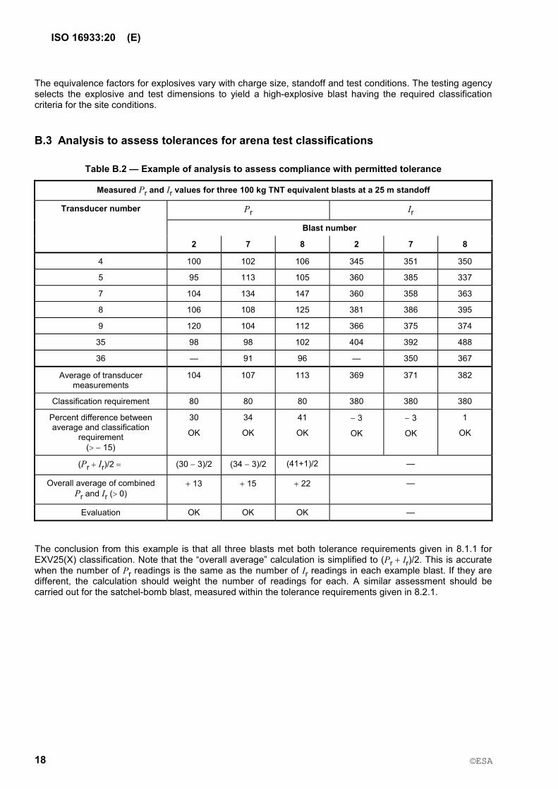
Table B.2 �— Example of analysis to assess compliance with permitted tolerance
Measured Pr and Ir values for three 100 kg TNT equivalent blasts at a 25 m standoff
Pr Ir
Blast number
Transducer number
2 7 8 2 7 8
4 100 102 106 345 351 350
5 95 113 105 360 385 337
7 104 134 147 360 358 363
8 106 108 125 381 386 395
9 120 104 112 366 375 374
35 98 98 102 404 392 488
36 �— 91 96 �— 350 367
Average of transducer measurements
104 107 113 369 371 382
Classification requirement 80 80 80 380 380 380
Percent difference between average and classification
requirement ( 15)
30
OK
34
OK
41
OK
3
OK
3
OK
1
OK
(Pr Ir)/2 (30 3)/2 (34 3)/2 (41+1)/2 �—
Overall average of combined Pr and Ir ( 0)
13 15 22 �—
Evaluation OK OK OK �—
The conclusion from this example is that all three blasts met both tolerance requirements given in 8.1.1 for EXV25(X) classification. Note that the �“overall average�” calculation is simplified to (Pr Ir)/2. This is accurate when the number of Pr readings is the same as the number of Ir readings in each example blast. If they are different, the calculation should weight the number of readings for each. A similar assessment should be carried out for the satchel-bomb blast, measured within the tolerance requirements given in 8.2.1.

ISO 16933:20 (E)
19
Annex C (informative)
Nominal charge size and standoff distances
C.1 Nominal charge size and standoff distance for vehicle-bomb classifications
The blast values given in Table 2 are those which can be achieved on the surface of 3,15 m wide 3,15 m high test frames (cubicle reaction structures) that face explosive charges of 100 kg TNT equivalent at the standoff distances denoted in the classification code. They relate to charges placed at a height, to mid-point, of up to about 1,2 m above a hard surface extending between the charge and the target. The supposition within this International Standard is that these are reflected blast values where the surface of the test specimen is normal to the line between the centres of the specimen and the charge. However, different orientations, charge masses and test-frame sizes are permissible, provided that the test specimen experiences the required blast values normal to the specimen surface. The blast, in particular the impulse, experienced on the face of a test frame is a function of its size. The impulse on a small test frame can be up to 30 % less than that on the face of a large building owing to the phenomenon of blast �“clearing�” from the edges. It is the responsibility of the testing agency to achieve the classification-blast values by selection of appropriate combinations of frame size, charge mass, charge composition and standoff, taking into account other test-site conditions such as altitude and hardness of the ground surface.
Table C.1 shows the classification values from Table 2, with the nominal standoffs from 100 kg TNT charges to small test cubicles, compared against the nominal charge size and standoff distances that are calculated to achieve the same classification values on large facades.
Table C.1 �— Nominal charge sizes and standoff distances for typical test frames compared to those normal to a large facade calculated to equate to the blast values for the vehicle-bomb classifications
Classification criteria blast valuesa
Calculated nominal equivalentsc to a large facade
Classification code Pressure
kPa
Impulse
kPa-ms
Nominal standoffsb of approx. 100 kg TNT for a small test frame
m
TNT equivalent charge size
kg
Standoff distance
m
EXV45(X) 30 180 45 30 32
EXV33(X) 50 250 33 30 23
EXV25(X) 80 380 25 40 19
EXV19(X) 140 600 19 64 17
EXV15(X) 250 850 15 80 14,4
EXV12(X) 450 1200 12 100 12,4
EXV10(X) 800 1600 10 125 11
a See Table 2.
b Derived from test measurements of reflected blast values on the face of vertical 3,15 m 3,15 m test frames positioned at standoffs from 100 kg TNT equivalent charges placed 1,2 m above a hard surface to exceed the classification criteria.
c Calculated assuming hemispherical surface bursts on the ground at standoffs normal to the vertical face of large facades.

ISO 16933:20 (E)
20
C.2 Nominal charge size and standoff distances for hand-carried satchel-bomb classifications
The satchel-bomb-classification blast values given in Table 3 are based upon measurements recorded during tests undertaken using carefully formed spheres of TNT placed at the standoff distances listed in Table C.2. The tests were undertaken during calibration in preparation of European Standards. The 3 kg charges were placed at a height of 0,5 m to centre above a hard surface. The 12 kg and 20 kg charges were placed at a height of 0,8 m to centre above a hard surface.
For such close standoffs, the distance-to-blast measurement points becomes critical. Points on the target, such as at a top corner, are related to the centre of the charge by lines that diverge horizontally and/or vertically from the shortest, perpendicular distance. These slant distances and angles of incidence, and hence the blast values, vary significantly across the face of the targets. The blast values given are each derived from the mean values of several blast gauges distributed across a face area representing a test specimen of size 1,6 m 1,3 m; set with bottom edge at 0,5 m above ground within a concrete transducer wall representing a test frame of size 2,4 m 2,4 m. The resulting mean values from several tests were then averaged and rounded down to provide a realistic, achievable set of mean values to be applied as classification values to the centre of a test specimen. It should be noted that peak values experienced near the bottom centre of the test specimen target areas were typically 10 % to 20 % higher than the mean values.
In recognition of the above derivations, the maximum tolerance allowed on blast values for the satchel-bomb classifications is only 10 %. The test values applicable to the centre of the test specimen for comparison with the classification criteria are to be computed from at least three gauges distributed around the face of the target area or within the simulated area if a separate transducer panel is used (see 6.5.1).
Table C.2 �— Nominal charge sizes and standoff distances for typical test frames compared to those normal to a large facade calculated to equate to the blast values for the satchel-bomb classifications
Classification criteria blast valuesa
Nominal charge mass and standoffsb for a small test frame
Calculated nominal equivalentsc to a large facade
Classification code Pressure
kPa
Impulse
kPa-ms
TNT equivalent charge size
kg
Standoff distance
m
TNT equivalent charge size
kg
Standoff distance
m
SB1(X) 70 150 3 9 3,25 9,00
SB2(X) 110 200 3 7 3,50 7,26
SB3(X) 250 300 3 5 3,50 5,07
SB4(X) 800 500 3 3 3,70 3,40
SB5(X) 700 700 12 5,5 12,00 5,26
SB6(X) 1600 1000 12 4 12,60 4,06
SB7(X) 2800 1500 20 4 21,00 4,00
a See Table 3.
b Derived from test measurements of reflected blast values on the face of vertical 2,4 m 2,4 m test frames positioned at the standoffs listed from charges of TNT equivalent mass listed to exceed the classification criteria. The charges were positioned at the distances above the hard surfaces as defined above.
c Calculated assuming hemispherical surface bursts on the ground at standoffs normal to the vertical face of large facades.

ISO 16933:20 (E)
21
Annex D (informative)
Fragment definitions and criteria comparisons
D.1 Fragment dimensions
A fragment (3.7) in this International Standard is defined as any particle with a united dimension of 25 mm or greater.
The united dimension of a glass particle is determined by adding its width and length and thickness. Glazing dust and slivers are all other smaller particles. These definitions accord with ASTM F1642.
In order to aid data collection, this definition is quantified in Table D.1, which shows examples of minimum sizes classed as fragments for typical glass thicknesses:
Table D.1 �— Relationship of dimensions, volume and mass for framents
Particle dimensions a
mm
Volume
mm3
Mass b
g
10 12 3 360 0,90
10 11 4 440 1,10
10 9 6 540 1,35
8 8 8 576 1,44
9 10 10 540 1,35
6 16 3 288 0,72
6 15 4 360 0,90
6 13 6 468 1,17
6 11 8 528 1,32
a The sum of the three dimensions equals 25 mm, in accordance with the definition of a gragment (3.7).
b Assuming a density of 0,002 5 g/mm3. 1 m2 of 10 mm thick glass weighs 25 kg assuming a glass density 2 500 kg/m3.
D.2 Hazard rating
Hazard ratings resulting from tests of glazing may be used for estimation of the glazing performance under other conditions based on theoretical considerations and/or experimental work.
D.3 Criteria assessments and comparisons
Further information on assessing blast, tests, criteria and effects on glazing may be found in Reference [8], which contains charts that plot pressure against impulse and indicate estimated relationships between glazing thickness, type and size. This reference and charts show the test-classification blast values applicable to small-reaction structures related to a grid of calculated values for large facades. Arena test classifications and effects are compared with those of the shock tube test classifications as in Reference [2].

ISO 16933:20 (E)
22
Bibliography
[1] ASTM F1642, Standard Test Method for Glazing and Glazing Systems Subject to Airblast Loadings
[2] ISO 16934, Glass in buildings �— Explosion resistant security glazing �— Test and classification by shock-tube loading
[3] EN 13123-1, Windows, doors and shutters �— Explosion resistance �— Requirements and classification �— Part 1: Shock tube
[4] EN 13123-2, Windows, doors and shutters �— Explosion resistance �— Requirements and classification �— Part 2: Range test
[5] EN 13124-1, Windows, doors and shutters �— Explosion resistance �— Test method �— Part 1: Shock tube
[6] EN 13124-2, Windows, doors and shutters �— Explosion resistance �— Test method �— Part 2: Range test
[7] EN 135412), Glass in building �— Security glazing �— Testing and classification of resistance against explosion pressure
[8] Johnson, N. F. International Standards for Blast Resistant Glazing, Paper ID JAI 12892, Journal of ASTM International, April 2006, 3, (4); ISSN: 1546-962X 3)
2) EN 13541 is based on simulating blast using a shock tube, as are References [2], [3] and [4].
3) Available online at http://www.astm.org. To download ($25 fee): proceed through / Books & Journals / Journal of ASTM International (JAI) / Search; enter �“blast�” in the space for the title of paper or �“International Standards for Blast Resistant Glazing�”.

The Head Office of ESA is at Addis Ababa.
011-‐ 646 06 85, 011-‐ 646 05 65 011-‐646 08 80 2310 Addis Ababa, Ethiopia
E-‐mail: [email protected], Website: www.ethiostandards.org
Organization and Objectives
The Ethiopian Standards Agency (ESA) is the national standards body of Ethiopia established in 2010 based on regulation No. 193/2010.ESA is established due to the restructuring of Quality and Standards Authority of Ethiopia (QSAE) which was established in 1970.
ESA’s objectives are:-
Develop Ethiopian standards and establish a system that enable to check weather goods and services are in compliance with the required standards,
Facilitate the country’s technology transfer through the use of standards,
Develop national standards for local products and services so as to make them competitive in the international market.
Ethiopian Standards
The Ethiopian Standards are developed by national technical committees which are composed of different stakeholders consisting of educational Institutions, research institutes, government organizations, certification, inspection, and testing organizations, regulatory bodies, consumer association etc. The requirements and/ or recommendations contained in Ethiopian Standards are consensus based that reflects the interest of the TC representatives and also of comments received from the public and other sources. Ethiopian Standards are approved by the National Standardization Council and are kept under continuous review after publication and updated regularly to take account of latest scientific and technological changes. Orders for all Ethiopian Standards, International Standard and ASTM standards, including electronic versions, should be addressed to the Documentation and Publication Team at the Head office and Branch (Liaisons) offices. A catalogue of Ethiopian Standards is also available freely and can be accessed in from our website.
ESA has the copyright of all its publications. No part of these publications may be reproduced in any form without the prior permission in writing of ESA. International Involvement ESA, representing Ethiopia, is a member of the International Organization for Standardization (ISO), and Codex Alimentarius Commission (CODEX). It also maintains close working relations with the international Electro-technical Commission (IEC) and American Society for Testing and Materials (ASTM).It is a founding member of the African Regional Organization for standardization (ARSO).
More Information?
Contact us at the following address.
Standard Mark
Eth
iopi
an S
tand
ards
Age
ncy
DRAFT