ET 200eco Distributed I/O Station Fail-Safe I/O Module · 4 Address Assignment and Installation ......
104
s Contents Preface 1 Product Overview 2 Configuration and Parameter Assignment 3 Address Assignment and Installation 4 Wiring 5 Diagnostics 6 General Technical Specifications 7 Digital F I/O Module 8 Appendices Accessories and Order Numbers 9 Response Times 10 Glossary 11 Index SIMATIC ET 200eco Distributed I/O Station Fail-Safe I/O Module Manual Edition 06/2004 A5E00297494-02 The following supplement is part of this documentation: No. Product Information Drawing number Edition 1 Address Assignment in the F-CPU; UL/CSA Approval; Parameter "Behavior after Channel Faults"; Section 8.2.4 Application 3: Safety Mode AK6/SIL3/Category 4 A5E00470176-02 04/2007
-
Upload
vuongkhuong -
Category
Documents
-
view
214 -
download
0
Transcript of ET 200eco Distributed I/O Station Fail-Safe I/O Module · 4 Address Assignment and Installation ......

s
Contents Preface 1 Product Overview 2 Configuration and Parameter Assignment 3 Address Assignment and Installation 4 Wiring 5 Diagnostics 6 General Technical Specifications 7 Digital F I/O Module 8 Appendices Accessories and Order Numbers 9 Response Times 10 Glossary 11 Index
SIMATIC
ET 200eco Distributed I/O Station Fail-Safe I/O Module Manual
Edition 06/2004 A5E00297494-02
The following supplement is part of this documentation:
No. Product Information Drawing number Edition
1 Address Assignment in the F-CPU; UL/CSA Approval; Parameter "Behavior after Channel Faults"; Section 8.2.4 Application 3: Safety Mode AK6/SIL3/Category 4
A5E00470176-02 04/2007

Copyright Siemens AG 2004 All rights reserved The reproduction, transmission or use of this document or its contents is not permitted without express written authority. Offenders will be liable for damages. All rights, including rights created by patent grant or registration of a utility model or design, are reserved. Siemens AG Bereich Automation and Drives Geschaeftsgebiet Industrial Automation Systems Postfach 4848, D- 90327 Nuernberg
Disclaimer of Liability We have checked the contents of this manual for agreement withthe hardware and software described. Since deviations cannot beprecluded entirely, we cannot guarantee full agreement. However,the data in this manual are reviewed regularly and any necessarycorrections included in subsequent editions. Suggestions forimprovement are welcomed. Siemens AG 2004 Technical data subject to change.
Siemens Aktiengesellschaft A5E00297494-02
Safety Guidelines
This manual contains notices intended to ensure personal safety, as well as to protect the products and connected equipment against damage. These notices are highlighted by the symbols shown below and graded according to severity by the following texts:
! Danger indicates that death, severe personal injury or substantial property damage will result if proper precautions are not taken.
! Warning indicates that death, severe personal injury or substantial property damage can result if proper precautions are not taken.
! Caution indicates that minor personal injury can result if proper precautions are not taken.
Caution
indicates that property damage can result if proper precautions are not taken.
Notice draws your attention to particularly important information on the product, handling the product, or to a particular part of the documentation.
Qualified Personnel
Only qualified personnel should be allowed to install and work on this equipment. Qualified persons are defined as persons who are authorized to commission, to ground and to tag circuits, equipment, and systems in accordance with established safety practices and standards.
Correct Usage
Note the following:
! Warning This device and its components may only be used for the applications described in the catalog or the technical description, and only in connection with devices or components from other manufacturers which have been approved or recommended by Siemens. This product can only function correctly and safely if it is transported, stored, set up, and installed correctly, and operated and maintained as recommended.
Trademarks
SIMATIC®, SIMATIC HMI® and SIMATIC NET® are registered trademarks of SIEMENS AG.
Third parties using for their own purposes any other names in this document which refer to trademarks might infringe upon the rights of the trademark owners.

ET 200eco Distributed I/O Station Fail-Safe I/O Module A5E00297494-02 iii
Contents
1 Preface ............................................................................................................................ 1-1
2 Product Overview........................................................................................................... 2-1 2.1 Introduction ....................................................................................................... 2-1 2.2 Using the Fail-Safe ET 200eco I/O Module..................................................... 2-2 2.3 Guide to Commissioning the Fail-Safe ET 200eco I/O Module
on PROFIBUS DP ............................................................................................ 2-6 3 Configuration and Parameter Assignment.................................................................. 3-1
4 Address Assignment and Installation.......................................................................... 4-1 4.1 Introduction ....................................................................................................... 4-1 4.2 Address Assignment in the F-CPU................................................................... 4-1 4.3 Assigning PROFIsafe Address ......................................................................... 4-3 4.4 Installation......................................................................................................... 4-5
5 Wiring .............................................................................................................................. 5-1 5.1 Introduction ....................................................................................................... 5-1 5.2 Safe Functional Extra-Low Voltage for the Fail-Safe I/O Module.................... 5-2 5.3 Wiring a Fail-Safe I/O Module .......................................................................... 5-3 5.4 Replacing a Fail-Safe I/O Module..................................................................... 5-4 5.5 Sensor Requirements ....................................................................................... 5-5
6 Diagnostics..................................................................................................................... 6-1 6.1 Introduction ....................................................................................................... 6-1 6.2 Reactions to Faults ........................................................................................... 6-1 6.3 Fault Diagnostics .............................................................................................. 6-3
7 General Technical Specifications................................................................................. 7-1 7.1 Introduction ....................................................................................................... 7-1 7.2 Standards and Approvals ................................................................................. 7-2 7.3 Electromagnetic Compatibility .......................................................................... 7-7 7.4 Transport and Storage Conditions.................................................................. 7-11 7.5 Mechanical and Climatic Environmental Conditions ...................................... 7-12 7.6 Specifications for Nominal Line Voltages, Isolation Tests,
Protection Class, and Type of Protection ....................................................... 7-14

Contents
ET 200eco Distributed I/O Station Fail-Safe I/O Module iv A5E00297494-02
8 Digital F I/O Module........................................................................................................ 8-1 8.1 Introduction ....................................................................................................... 8-1 8.2 Fail-Safe ET 200eco I/O Module 4/8 F-DI 24 VDC PROFIsafe....................... 8-2 8.2.1 Use Cases of the ET 200eco 4/8 F-DI..............................................................8-8 8.2.2 Use Case 1: Safety Mode AK4/SIL2/Category 3............................................8-10 8.2.3 Use Case 2: Safety Mode AK6/SIL3/Category 3............................................8-12 8.2.4 Use Case 3: Safety Mode AK6/SIL3/Category 4............................................8-21 8.2.5 Diagnostic Functions of the ET 200eco 4/8 F-DI............................................8-25 8.2.6 Technical Specifications of the ET 200eco 4/8 F-DI ......................................8-28
9 Accessories and Order Numbers ................................................................................. 9-1
10 Response Times........................................................................................................... 10-1
11 Glossary........................................................................................................................ 11-1
Index

ET 200eco Distributed I/O Station Fail-SafeI/O Module A5E00297494-02 1-1
1 Preface
Purpose of this Manual The information in this manual is a reference source for operations, function descriptions, and technical specifications of the ET 200eco fail-safe I/O module.
Basic Knowledge Requirements This manual is a supplement to the ET 200eco Distributed I/O Station manual. You require a general knowledge in the field of automation engineering to be able to understand this manual. You also require experience of using the STEP 7 basic software and the ET 200eco distributed I/O station.
Scope of this Manual
Module Order Number Release Version and Higher
Digital I/O module 4/8 F-DI DC24V PROFIsafe
6ES7 148-3FA00-0XB0 01

Preface
ET 200eco Distributed I/O Station Fail-SafeI/O Module 1-2 A5E00297494-02
Approvals See Section 7.2 Standards and Approvals.
The fail-safe ET 200eco I/O module also certified for use in safety mode up to:
• Requirements class (AK) 6 in accordance with DIN V 19250 (DIN V VDE 0801)
• Safety class SIL3 (Safety Integrity Level) in accordance with IEC 61508
• Category 4 in accordance with EN 954-1
CE Certification See Section 7.2 Standards and Approvals.
Certification Mark for Australia (C-Tick Mark) See Section 7.2 Standards and Approvals.
Standards See Section 7.2 Standards and Approvals.
Position in the Information Landscape When working with the ET 200eco fail-safe I/O module, you will need to consult the supplementary documentation listed below depending on your particular application. This manual refers to the supplementary documentation as needed.
Documentation Brief Description of Relevant Contents ET 200eco Distributed I/O Station manual
Describes all general aspects of the ET 200eco hardware (including assembly, installation and wiring of the ET 200eco)
Safety Engineering in SIMATIC S7 system description
• Provides an overview of the implementation, configuration, and method of operation of S7 Distributed Safety and S7 F/FH fail-safe automation systems
• Contains a summary of detailed technical information concerning fail-safe engineering in S7-300 and S7-400
• Includes monitoring and response time calculations for S7 Distributed Safety and S7 F/FH fail-safe systems
For integration in the S7 F/FH fail-safe system
• The S7 F/FH Automation Systems manual describes the tasks that must be performed to commission an S7 F/FH fail-safe system.
• The S7-400, M7-400 Programmable Controllers Hardware and Installation manual describes the installation and wiring of S7-400 systems.
• The S7-400H Programmable Controllers, Fault-Tolerant Systems manual describes the CPU 41x-H central modules and the tasks required to set up and commission an S7-400H fault-tolerant system.
• The CFC for SIMATIC S7 manual/online help provides a description of programming with CFC.
Preface
ET 200eco Distributed I/O Station Fail-SafeI/O Module A5E00297494-02 1-3
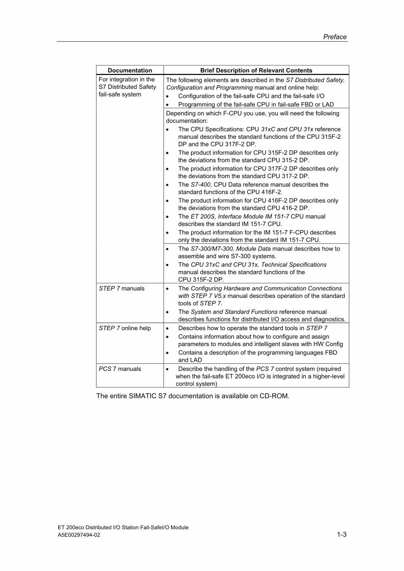
Documentation Brief Description of Relevant Contents The following elements are described in the S7 Distributed Safety, Configuration and Programming manual and online help: • Configuration of the fail-safe CPU and the fail-safe I/O • Programming of the fail-safe CPU in fail-safe FBD or LAD Depending on which F-CPU you use, you will need the following documentation: • The CPU Specifications: CPU 31xC and CPU 31x reference
manual describes the standard functions of the CPU 315F-2 DP and the CPU 317F-2 DP.
• The product information for CPU 315F-2 DP describes only the deviations from the standard CPU 315-2 DP.
• The product information for CPU 317F-2 DP describes only the deviations from the standard CPU 317-2 DP.
• The S7-400, CPU Data reference manual describes the standard functions of the CPU 416F-2.
• The product information for CPU 416F-2 DP describes only the deviations from the standard CPU 416-2 DP.
• The ET 200S, Interface Module IM 151-7 CPU manual describes the standard IM 151-7 CPU.
• The product information for the IM 151-7 F-CPU describes only the deviations from the standard IM 151-7 CPU.
For integration in the S7 Distributed Safety fail-safe system
• The S7-300/M7-300, Module Data manual describes how to assemble and wire S7-300 systems.
• The CPU 31xC and CPU 31x, Technical Specifications manual describes the standard functions of the CPU 315F-2 DP.
STEP 7 manuals • The Configuring Hardware and Communication Connections with STEP 7 V5.x manual describes operation of the standard tools of STEP 7.
• The System and Standard Functions reference manual describes functions for distributed I/O access and diagnostics.
STEP 7 online help • Describes how to operate the standard tools in STEP 7 • Contains information about how to configure and assign
parameters to modules and intelligent slaves with HW Config • Contains a description of the programming languages FBD
and LAD PCS 7 manuals • Describe the handling of the PCS 7 control system (required
when the fail-safe ET 200eco I/O is integrated in a higher-level control system)
The entire SIMATIC S7 documentation is available on CD-ROM.

Preface
ET 200eco Distributed I/O Station Fail-SafeI/O Module 1-4 A5E00297494-02
Guide This manual describes the fail-safe 4/8 F-DI I/O module of the ET 200eco distributed I/O station. It consists of instructions and reference material (technical specifications and appendices)
• This manual covers the following basic aspects of the fail-safe I/O module:
• Design and use
• Configuring and assigning parameters
• Addressing, mounting, and wiring
• Diagnostic evaluation
• Technical specifications
• Order numbers
Conventions In this manual, the terms "safety engineering" and "fail-safe engineering" are used synonymously. The same applies to the terms "fail-safe“ and "F-“ and to the terms "fail-safe I/O module" and "ET 200eco 4/8 F-DI".
"S7 Distributed Safety" and "S7 F Systems" in italics refer to the optional packages for the two fail-safe systems: "S7 Distributed Safety" and "S7 F/FH Systems".
Recycling and Disposal Due to the low levels of pollutants it contains, the fail-safe ET 200eco I/O module can be recycled. For proper recycling and disposal of your old module (device), consult a certified disposal facility for electronic scrap.
Additional Support If you have any additional questions about the use of products presented in this manual, contact your local Siemens representative:
http://www.siemens.com/automation/partner

Preface
ET 200eco Distributed I/O Station Fail-SafeI/O Module A5E00297494-02 1-5
Training Center We offer courses to help you get started with the S7 automation system. Contact your regional training center or the central training center in Nuremberg (90327), Federal Republic of Germany. Telephone +49 (911) 895–3200 Internet: http://www.sitrain.com
H/F Competence Center
The H/F Competence Center in Nuremberg offers special workshops on SIMATIC S7 fail-safe and fault tolerant (high availability) automation systems. The H/F Competence Center can also provide assistance with onsite configuration, commissioning, and troubleshooting.
Telephone: +49 (911) 895-4759 Fax: +49 (911) 895-5193
For questions about workshops, etc.: [email protected]

Preface
ET 200eco Distributed I/O Station Fail-SafeI/O Module 1-6 A5E00297494-02
Automation and Drives, Service & Support Available worldwide, 24 hours a day:
Beijing
Nuernberg
Johnson City
Worldwide (Nuernberg) Technical Support
24 hours a day, 365 days a year
Phone: +49 (180) 5050-222
Fax: +49 (180) 5050-223
mailto:[email protected]
GMT: +1:00
Europe / Africa (Nuernberg) Authorization Local time: Mon.-Fri. 8:00 to 5:00 PM
Phone: +49 (180) 5050-222
Fax: +49 (180) 5050-223
mailto:[email protected]
GMT: +1:00
United States (Johnson City) Technical Support and Authorization Local time: Mon.-Fri. 8:00 to 5:00 PM
Phone: +1 (423) 262 2522
Fax: +1 (423) 262 2289
mailto:[email protected]
GMT: -5:00
Asia / Australia (Beijing) Technical Support and Authorization Local time: Mon.-Fri. 8:00 to 5:00 PM
Phone: +86 10 64 75 75 75
Fax: +86 10 64 74 74 74
mailto:[email protected]
GMT: +8:00
The languages of the SIMATIC Hotlines and the authorization hotline are generally German and English.
Preface
ET 200eco Distributed I/O Station Fail-SafeI/O Module A5E00297494-02 1-7
Service & Support on the Internet In addition to our documentation, we offer our Know-how online on the internet at: http://www.siemens.com/automation/service&support
where you will find the following:
• The newsletter, which constantly provides you with up-to-date information on your products.
• The right documents via our Search function in Service & Support.
• A forum, where users and experts from all over the world exchange their experiences.
• Your local representative for Automation & Drives.
• Information on field service, repairs, spare parts and more under "Services".
Preface
ET 200eco Distributed I/O Station Fail-SafeI/O Module 1-8 A5E00297494-02
ET 200eco Distributed I/O Station Fail-SafeI/O Module A5E00297494-02 2-1
2 Product Overview
2.1 Introduction
Overview This chapter provides information about the following topics:
• How the fail-safe ET 200eco I/O module fits into the fail-safe SIMATIC S7 automation systems
• The components that make up the fail-safe ET 200eco I/O module
• The steps you need to take to commission the fail-safe ET 200eco I/O module in PROFIBUS DP
Important Note for Maintaining Operational Safety of Your System
Note The operators of systems with safety-related characteristics must adhere to operational safety requirements. The supplier is also obliged to comply with special product monitoring measures. To keep you informed, a special newsletter is therefore available containing information on product developments and properties that are important (or potentially important) for operating systems where safety is an issue. By subscribing to the appropriate newsletter, you will ensure that you are always up-to-date and able to make changes to your system, when necessary. Please connect to the following Internet address http://my.ad.siemens.de/myAnD/guiThemes2Select.asp?subjectID=2&lang=en and register for the following Newsletter:
• SIMATIC S7-300
• SIMATIC S7-400
• Distributed I/O
• SIMATIC Industrial Software
To receive these newsletters, select the "Updates" check box.
Product Overview
ET 200eco Distributed I/O Station Fail-SafeI/O Module 2-2 A5E00297494-02
2.2 Using the Fail-Safe ET 200eco I/O Module
What is a Fail-Safe Automation System? Fail-safe automation systems (F-systems) are used in systems with higher-level safety requirements. F-systems are used to control systems having a safe state immediately after shutdown. That is, F-systems control processes in which an immediate shutdown does not endanger humans or the environment.
What is the ET 200eco Distributed I/O Station? The ET 200eco distributed I/O station is a compact DP slave in PROFIBUS DP that can consist of one fail-safe I/O module.
You can use copper cables to configure PROFIBUS-DP chains.
What is a Fail-Safe I/O Module? The essential difference between the fail-safe I/O module and the standard -ET 200eco I/O modules is that it has a two-channel design. The two integrated processors monitor each other, automatically test the input and output circuits, and switch the F-I/O module to a safe state in the event of a fault. The F-CPU communicates with the F-I/O module using the PROFIsafe safety-related bus profile.
Possible Uses of the Fail-Safe ET 200eco I/O Module The use of ET 200eco fail-safe I/O modules allows conventional configurations in safety engineering to be replaced with PROFIBUS-DP components. This includes replacement of switching devices for emergency stop, protective door monitors, two-hand operation, etc.
Product Overview
ET 200eco Distributed I/O Station Fail-SafeI/O Module A5E00297494-02 2-3
Use in F-Systems Fail-safe ET 200eco I/O modules can be used:
• In the S7 Distributed Safety F-system with the S7 Distributed Safety optional package as of version V 5.2
• In S7 F/FH systems with the S7 F Systems optional package as of version V 5.2
The F Configuration Pack V 5.3 Service Pack 2 or higher must be installed (see Chapter 3).
When using fail-safe ET 200eco I/O modules in F-systems, the information in the following manuals applies:
• ET 200eco Distributed I/O Station
• Safety Engineering in SIMATIC S7
• S7 Distributed Safety, Configuration and Programming or Programmable Controllers S7 F/FH Systems
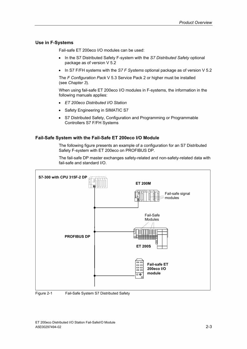
Fail-Safe System with the Fail-Safe ET 200eco I/O Module The following figure presents an example of a configuration for an S7 Distributed Safety F-system with ET 200eco on PROFIBUS DP.
The fail-safe DP master exchanges safety-related and non-safety-related data with fail-safe and standard I/O.
S7-300 with CPU 315F-2 DP ET 200M
Fail-safe signal modules
PROFIBUS DP
ET 200S
Fail-Safe Modules
Fail-safe ET 200eco I/O module
Figure 2-1 Fail-Safe System S7 Distributed Safety
Product Overview
ET 200eco Distributed I/O Station Fail-SafeI/O Module 2-4 A5E00297494-02
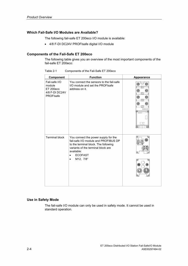
Which Fail-Safe I/O Modules are Available? The following fail-safe ET 200eco I/O module is available:
• 4/8 F-DI DC24V PROFIsafe digital I/O module
Components of the Fail-Safe ET 200eco The following table gives you an overview of the most important components of the fail-safe ET 200eco:
Table 2-1 Components of the Fail-Safe ET 200eco
Component Function Appearance Fail-safe I/O module ET 200eco 4/8 F-DI DC24V PROFIsafe
You connect the sensors to the fail-safe I/O module and set the PROFIsafe address on it.
Terminal block You connect the power supply for the fail-safe I/O module and PROFIBUS DP to the terminal block. The following variants of the terminal block are available: • ECOFAST • M12, 7/8“
Use in Safety Mode The fail-safe I/O module can only be used in safety mode. It cannot be used in standard operation.

Product Overview
ET 200eco Distributed I/O Station Fail-SafeI/O Module A5E00297494-02 2-5
Achievable Safety Classes The fail-safe I/O module is equipped for safety mode with integrated safety function.
The following safety classes can be achieved by making suitable parameter settings for the user safety functions in STEP 7 with the S7 Distributed Safety or S7 F Systems optional package and by arranging and wiring the sensors accordingly:
Table 2-2 Achievable Safety Classes in Safety Mode
Safety Class in Safety Mode In Accordance with IEC 61508
In Accordance with DIN V 19250
In Accordance with EN 954-1
SIL2 AK4 Category 3 SIL3 AK6 Category 3 SIL3 AK6 Category 4

Product Overview
ET 200eco Distributed I/O Station Fail-SafeI/O Module 2-6 A5E00297494-02
2.3 Guide to Commissioning the Fail-Safe ET 200eco I/O Module on PROFIBUS DP
Introduction The following table lists all the important steps you need to take to commission the fail-safe ET 200eco distributed I/O module as a DP slave on PROFIBUS DP.
Steps in Commissioning the Fail-Safe ET 200eco I/O Module
Table 2-3 Steps in Commissioning the Fail-Safe ET 200eco I/O Module
Step Procedure See ... 1. Configuring and assigning parameters to
the ET 200eco 4/8 F-DI in STEP 7 Chapter 3 and Chapter 8
2. Setting the PROFIsafe address on the ET 200eco 4/8 F-DI
Chapter 4
3. Installing the ET 200eco 4/8 F-DI Chapter 4 4. Wiring the ET 200eco 4/8 F-DI Chapter 5 5. Commissioning the ET 200eco 4/8 F-DI on
PROFIBUS DP ET 200eco Distributed I/O Station manual
6. If commissioning was not successful, run diagnostics on the ET 200eco 4/8 F-DI
Chapter 6, Chapter 8 and ET 200eco Distributed I/O Station manual
Note
You must configure and assign parameters to the fail-safe I/O module in STEP 7 before commissioning it.
Reason: The PROFIsafe address of the fail-safe I/O module is assigned automatically by STEP 7. You must set this PROFIsafe address on each failsafe I/O -module by means of switches before installing the module.

ET 200eco Distributed I/O Station Fail-SafeI/O Module A5E00297494-02 3-1
3 Configuration and Parameter Assignment
Requirements One of the following optional packages must be installed in STEP 7 before you can configure and assign parameters for the fail-safe I/O module.
• S7 Distributed Safety, Version V5.2 Service Pack 2 or higher
• S7 F Systems, Version V5.2 Service Pack 1 or higher
The following requirements also apply to the ET 200eco 4/8 F-DI:
• STEP 7 V 5.2 and higher
• F Configuration Pack V 5.3 service pack 2 and higher
The F Configuration Pack can be downloaded over the Internet from: http://www.siemens.com/automation/service&support. This ships with the optional packages S7 Distributed Safety V 5.2 Service Pack 2 or higher and S7 F Systems V 5.2 Service Pack 1 or higher.
Configuration Follow the usual procedure with STEP 7 HW Config to configure the fail-safe I/O module (in the same way as standard ET 200eco modules).
Parameter Assignment to set the I/O Module Properties To set the properties of the fail-safe I/O module:
1. Select the I/O module in STEP 7 HW Config.
2. Double-click on the "Slot 1" row of the I/O module. Or: Select the menu command Edit > Object Properties.
Parameters are downloaded from the programming device to the F-CPU of the DP master, where they are stored and then transferred to the fail-safe I/O module.
Where to Find Parameter Descriptions You will find a description of fail-safe module parameter settings in Chapter 8.
PROFIsafe Address and PROFIsafe Address Assignment You can find a description of PROFIsafe addresses and the address assignment procedure in Chapter 4.

Configuration and Parameter Assignment
ET 200eco Distributed I/O Station Fail-SafeI/O Module 3-2 A5E00297494-02
Bus Parameter Settings for PROFIBUS DP To comply with the values for electromagnetic compatibility, if you are using transmission rates less than 6 Mbps, you must increase the bus parameter "Retry Limit" to at least "3". Leave all other bus parameter default settings for the bus profile you are using.
Follow the steps outlined below in HW Config:
1. Open the "General" tab and select Properties > "Network Settings" tab in the DP master system.
3. Set "User-defined" in the Profile.
4. Select the Bus parameters and increase the "Retry Limit" from "1" to "3".
5. Exit the Bus Parameters dialog with "OK".
6. Open the Bus Parameters dialog again.
7. Click the Recalculate button.
8. Exit the Bus Parameters dialog with "OK".
Note
Remember that whenever you make a change to the DP master system (for example adding a new DP slave), you must subsequently click on the Recalculate button in the Bus Parameters dialog.
If you change to a transmission rate higher than 6 Mbps, you should set the "DP" bus profile again.

ET 200eco Distributed I/O Station Fail-Safe I/O Module A5E00297494-02 4-1
4 Address Assignment and Installation
4.1 Introduction
Overview This section provides information on the following topics:
• Address assignment of the fail-safe I/O module in the F-CPU
• Assigning the PROFIsafe address for the fail-safe I/O module
• Installing the fail-safe I/O module
4.2 Address Assignment in the F-CPU
Address assignment The fail-safe I/O module occupies the following address areas on the F-CPU:
• For S7 Distributed Safety: in the process image range
• For S7 F/FH systems: in the entire I/O range (inside and outside the process image).
Table 4-1 Addresses Assigned to the F-I/O module
Occupied Bytes in the F-CPU: F-I/O module
In Input Range In Output Range
ET 200eco 4/8 F-DI x + 0 through x + 5 x + 0 through x + 3
x = Module start address

Address Assignment and Installation
ET 200eco Distributed I/O Station Fail-Safe I/O Module 4-2 A5E00297494-02
Addresses Occupied by Useful Data Of the addresses assigned to the fail-safe I/O module, the useful data occupies the following addresses in the F-CPU:
Table 4-2 Addresses Occupied by Useful Data
Bits Occupied on the F-CPU: Bytes on the F-CPU 7 6 5 4 3 2 1 0 ET 200eco 4/8 F-DI:
x+0 Channel 7
Channel 6
Channel 5
Channel 4
Channel 3
Channel 2
Channel 1
Channel 0
x = Module start address
! Warning You must only access the addresses occupied by the useful data. The other address ranges occupied by the fail-safe I/O module are for other functions including safety-related communication between the fail-safe I/O module and F-CPU in compliance with PROFIsafe.
In 1oo2 evaluation of sensors, only the less significant channel of the channels that are grouped as a result of the 1oo2 sensor evaluation can be accessed in the safety program.
Additional Information Detailed information on F-I/O access can be found in the S7 Distributed Safety, Configuring and Programming manual or the Programmable Controllers S7 F/FH Systems manual.

Address Assignment and Installation
ET 200eco Distributed I/O Station Fail-Safe I/O Module A5E00297494-02 4-3
4.3 Assigning PROFIsafe Address
PROFIsafe Address Each fail-safe I/O module has its own PROFIsafe address in addition to the PROFIBUS address. Before installing the fail-safe ET 200eco I/O module, you must first set the PROFIsafe address of the fail-safe I/O module on every fail-safe I/O module.
PROFIsafe Address Assignment The PROFIsafe addresses (F_source_address, F_destination_address) are assigned automatically during configuration of the fail-safe I/O module in STEP 7. The F_destination_address is displayed in binary format in the "DIP switch setting" parameter in the object properties of the fail-safe I/O module in HW Config.
You can change the configured F_destination_address in HW Config. To prevent addressing errors, however, we recommend using the automatically assigned F_destination_address.
Address Switch for Setting PROFIsafe Addresses On the terminal block of the fail-safe I/O module, there is an address switch (10-pin DIP switch, see Figure 8-1). With this address switch, you enter the PROFIsafe address (F_destination_address) of the fail-safe I/O module.
Note
Fail-safe ET 200eco I/O modules can only be used in safety mode.
Address Assignment and Installation
ET 200eco Distributed I/O Station Fail-Safe I/O Module 4-4 A5E00297494-02
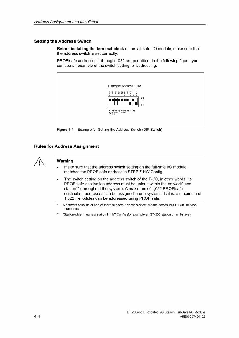
Setting the Address Switch Before installing the terminal block of the fail-safe I/O module, make sure that the address switch is set correctly.
PROFIsafe addresses 1 through 1022 are permitted. In the following figure, you can see an example of the switch setting for addressing.
Example: Address 1018
ON
OFF
9 8 7 6 5 4 3 2 1 0
8 1 6
3 2
6 4
1 2 8
2 5 6
5 1 2 4 2 1
Figure 4-1 Example for Setting the Address Switch (DIP Switch)
Rules for Address Assignment
! Warning • make sure that the address switch setting on the fail-safe I/O module
matches the PROFIsafe address in STEP 7 HW Config.
• The switch setting on the address switch of the F-I/O, in other words, its PROFIsafe destination address must be unique within the network* and station** (throughout the system). A maximum of 1,022 PROFIsafe destination addresses can be assigned in one system. That is, a maximum of 1,022 F-modules can be addressed using PROFIsafe.
* A network consists of one or more subnets. "Network-wide" means across PROFIBUS network boundaries.
** "Station-wide“ means a station in HW Config (for example an S7-300 station or an I-slave)

Address Assignment and Installation
ET 200eco Distributed I/O Station Fail-Safe I/O Module A5E00297494-02 4-5
4.4 Installation
Installing the Fail-Safe I/O Module The fail-safe I/O module belongs to the I/O module spectrum of ET 200eco. It is installed in the same way as all standard ET 200eco I/O modules.
For more information about module installation, refer to the ET 200eco Distributed I/O Station manual.

Address Assignment and Installation
ET 200eco Distributed I/O Station Fail-Safe I/O Module 4-6 A5E00297494-02

ET 200eco Distributed I/O Station Fail-Safe I/O Module A5E00297494-02 5-1
5 Wiring
5.1 Introduction
! Warning In order to prevent hazardous threats to persons or the environment, you must not under any circumstances override safety functions or implement measures that cause safety functions to be bypassed or that result in the bypassing of safety functions. The manufacturer is not liable for the consequences of such manipulations or for damages that result from failure to heed this warning.
Overview This chapter explains special features relating to wiring the ET 200eco fail-safe module. For more detailed information on this topic that applies equally to the fail-safe I/O module and the standard ET 200eco I/O module, refer to the Distributed I/O Station ET 200eco manual.

Wiring
ET 200eco Distributed I/O Station Fail-Safe I/O Module 5-2 A5E00297494-02
5.2 Safe Functional Extra-Low Voltage for the Fail-Safe I/O Module
Safe Functional Extra Low Voltage
! Warning The fail-safe I/O module must be operated with safe functional extra low voltage. This means that this module, even in the event of a fault, can only have a maximum voltage of Um applied to it. The following applies to all fail-safe I/O modules:
Um < 60.0 V
You can find additional information about safe functional extra low voltage, for example, in the data sheets of the applicable power supplies.
All components of the system that are capable of supplying electrical energy in any form must satisfy this requirement.
Each additional circuit (24 VDC) implemented must have a safe functional extra low voltage. Refer to the relevant data specification sheets or contact the manufacturer for information.
Note, also, that sensors having an external power supply can be connected to the fail-safe I/O module. Here, pay attention to the supply voltage from safe functional extra-low voltage. The process signal of a 24 VDC digital I/O module must not exceed a fault voltage of Um in the event of a fault.
! Warning All power sources, for example internal 24 V DC load voltage power supplies, external 24 V DC load voltage power supplies, 5 V DC bus voltage must be electrically connected externally. This prevents voltage additions in the individual voltage sources that would cause the fault voltage Um to be exceeded even if there are voltage differences. Make sure that there is sufficient line cross section for the electrical connection, in accordance with the ET 200eco configuration guidelines (see ET 200eco Distributed I/O Station manual).

Wiring
ET 200eco Distributed I/O Station Fail-Safe I/O Module A5E00297494-02 5-3
Power Supply Requirements in Compliance with NAMUR Recommendations
Note You must use only power packs or power supplies (230 VAC --> 24 VDC) with a power failure ride-through of at least 20 ms to comply with NAMUR recommendation NE 21, IEC 61131-2, and EN 298. The following power supply board components are available, for example:
S7-400:
• 6ES7 407-0KA01-0AA0 for 10 A
• 6ES7 407-0KR00-0AA0 for 10 A
S7-300:
• 6ES7 307-1BA00-0AA0 for 2 A
• 6ES7 307-1EA00-0AA0 for 5 A
• 6ES7 307-1KA00-0AA0 for 10 A
These requirements also apply, of course, to power packs and power supplies that do not have an S7-300 or S7-400 configuration.
5.3 Wiring a Fail-Safe I/O Module
Same Wiring Procedure as for ET 200eco The fail-safe ET 200eco I/O module belongs to the I/O module spectrum of ET 200eco.It is wired in the same way as all standard ET 200eco I/O modules.
For more information about wiring I/O modules, refer to the ET 200eco Distributed I/O Station manual.
! Warning When assigning signals of the fail-safe I/O module, remember that signals should only be routed within a cable or a nonmetallic sheathed cable if:
• A short circuit in the signals does not conceal a serious safety risk
• Signals are supplied by different sensor supplies of this fail-safe I/O module

Wiring
ET 200eco Distributed I/O Station Fail-Safe I/O Module 5-4 A5E00297494-02
5.4 Replacing a Fail-Safe I/O Module
Replacing a Fail-Safe I/O module During Operation A fail-safe I/O module can be replaced in exactly the same way as a standard ET 200eco I/O module (turn off the power to the I/O module, remove the module, connect up the new I/O module).
Note
Note that replacing a fail-safe ET 200eco I/O module during operation causes a communication error on the F-CPU. You must acknowledge the communication error in your safety program (for the response of the F-system after communication errors, output of a fail-safe value and user acknowledgment, refer to the manual S7 Distributed Safety, Configuration and Programming or Programmable Controllers S7 F/FH Systems).
! Caution Turn off the load power supply (2L+) before dismantling the terminal block. When the terminal block is dismantled, degree of protection IP 65, IP 66 or IP 67 no longer applies.
Remember to Set the PROFIsafe Address When replacing a fail-safe I/O module, make sure that the address switch (DIP switch) setting on the modules match (for information on the PROFIsafe address setting, see Chapter 4).
Note
Please refer to the information on dismantling and replacing the I/O module and the terminal block in the ET 200eco Distributed I/O Station manual.

Wiring
ET 200eco Distributed I/O Station Fail-Safe I/O Module A5E00297494-02 5-5
5.5 Sensor Requirements
General Requirements for Sensors Note the following important information for safety-related use of sensors:
! Warning The use of sensors is outside of our sphere of influence. We have equipped our electronics with such safety engineering features as to leave 85% of the maximum permissible probability of hazardous faults for sensors up to you. (This corresponds to the recommended load division in safety engineering between sensing devices, actuating devices, and electronic switching for input, processing, and output).
Note, therefore, that instrumentation with sensors involves a considerable safety responsibility. You should also bear in mind that sensors and actuators do not generally stand up to proof-test intervals of 10 years to IEC 61508 without considerable loss of safety.
The probability of hazardous faults and the rate of occurrence of hazardous faults of a safety function must comply with an upper limit determined by a safety integrity level (SIL). You will find a listing of values achieved by the fail-safe I/O module under "Safety-Related Characteristics" in the technical specifications for the fail-safe I/O module in Chapter 8.
To achieve SIL3 (AK6/Catefgory 4), suitably qualified sensors are necessary.
Requirements for the Duration of Sensor Signals
! Warning • To guarantee accurate detection of the sensor signals by the fail-safe I/O
module, make sure that the sensor signals have a certain minimum duration.
• In order for pulses to be detected with certainty, the time between two signal changes (pulse duration) must be greater than the PROFIsafe monitoring time.

Wiring
ET 200eco Distributed I/O Station Fail-Safe I/O Module 5-6 A5E00297494-02
Reliable acquisition by the fail-safe I/O module
The following table lists the minimum duration of the sensor signals for the fail-safe I/O module. This depends on the parameter settings for the short-circuit test and the input delay in STEP 7 (see Section 8.2).
Table 5-1 Minimum Duration of the Sensor Signals to Allow Correct Acquisition by the Fail-Safe I/O Module
Short-Circuit Test Parameter
Assigned Input Delay
3 ms 15 ms
Deactivated 9 ms 23 ms Activated 12 ms 37 ms
Reliable acquisition by the safety program on the F-CPU
You will find information on the times necessary for correct acquisition of the sensor signals in the safety program in Chapter 9 of the system description Safety Engineering in SIMATIC S7.
Technical Specifications of the Sensors Please refer to Chapter 8 for the technical specifications relating to the choice of sensors.

ET 200eco Distributed I/O Station Fail-Safe I/O Module A5E00297494-02 6-1
6 Diagnostics
6.1 Introduction
Overview This section provides information on the following topics:
• Reactions to faults of the fail-safe I/O module
• Diagnostics of the fail-safe I/O module if a fault occurs
6.2 Reactions to Faults
Safe State (Safety Concept) The basic principle behind the safety concept is the existence of a safe state for all process variables. For digital fail-safe I/O modules, the safe state is, for example, the value "0".
Reactions to Faults and Startup of the F-System The safety function requires that the fail-safe values (safe state) are used instead of the process values for a fail-safe I/O module in the following situations (passivation of the fail-safe I/O module):
• When the F-system is started up
• In the case of faults during safety-related communication between the F-CPU and fail-safe I/O module using the PROFIsafe safety protocol (communication fault).
• In the case of F-I/O or channel faults (for example, wire break, short circuit, discrepancy error)
! Warning For channels that you set to "deactivated" in STEP 7, there is no diagnostic reaction or error handling if a channel fault occurs, not even when such a channel is affected indirectly by a channel group error ("Channel activated/deactivated“ parameter, see Section 8.2).

Diagnostics
ET 200eco Distributed I/O Station Fail-Safe I/O Module 6-2 A5E00297494-02
Fail-safe Value Output for the Fail-Safe I/O Module For fail-safe input modules, if passivation occurs, the F-system provides fail-safe values for the safety program instead of the process values pending at the fail-safe inputs:
• For fail-safe digital input modules, this is always the fail-safe value 0.
Depending on which F-system is used and the type of fault that occurred (F-I/O, channel, or communication fault), fail-safe values are used either for the affected channel only or for all channels of the fail-safe I/O module involved.
Reintegration of a Fail-Safe I/O Module Switchover from fail-safe values to process values (reintegration of a fail-safe I/O module) occurs either automatically or only after user acknowledgement in the safety program. For a fail-safe input module, the process values pending at the fail-safe inputs are provided again for the safety program after reintegration.
Additional Information on Passivation and Reintegration For more detailed information on passivation and reintegration of F-I/O, refer to the S7 Distributed Safety, Configuring and Programming manual or Programmable Controllers S7 F/FH Systems manual.

Diagnostics
ET 200eco Distributed I/O Station Fail-Safe I/O Module A5E00297494-02 6-3
6.3 Fault Diagnostics
Definition Diagnostics can be used to determine whether faults occurred during signal acquisition by the fail-safe I/O module. Diagnostic information is assigned either to one channel or to the entire fail-safe I/O module.
Diagnostic Functions are not Critical to Safety Diagnostic functions (displays and messages) are not critical to safety and therefore are not designed to be safety-oriented functions. That is, they are not tested internally.
Diagnostic Options for the Fail-Safe I/O Module The following diagnostic options are available for the fail-safe I/O module:
• LED display on front panel of the I/O module
• Diagnostic functions of the fail-safe I/O module (slave diagnostics complying with the PROFIBUS standard IEC 61784-1:2002 Ed1 CP 3/1)
Diagnostic Functions that Cannot be Activated by the User The fail-safe I/O module provides diagnostic functions that cannot be deselected or influenced. This means that diagnostics are always activated and are automatically made available by the fail-safe I/O module in STEP 7 and passed on to the F-CPU in the event of a fault.
Diagnostic Functions that can be Assigned as Parameters You can activate certain diagnostic functions using parameter settings in STEP 7:
• short-circuit monitoring (short-circuit test parameter, see Section 8.2).
! Warning Diagnostic functions must be enabled or disabled in coordination with the application.

Diagnostics
ET 200eco Distributed I/O Station Fail-Safe I/O Module 6-4 A5E00297494-02
Diagnostics by LED Display The fail-safe I/O module indicates faults with its SF LED (group fault LED), for example faults in the internal sensor power supplies. The SF-LED lights up as soon as a diagnostic function is triggered by the fail-safe I/O module. The SF LED flashes when a fault is cleared but has not yet been acknowledged. It goes off when all faults/errors have been cleared and acknowledged.
The fail-safe I/O module also has an ON LED that displays the load voltage power supply of the voltage group. The ON LED is lit when the sensor power supply is present. The ON LED flashes when there is a fault in the sensor power supply.
The fail-safe I/O module also has a BF LED to indicate bus problems. The BF LED is lit/flashes as soon as there is a bus problem. The BF LED goes off, when all bus problems have been cleared.
Slave Diagnostics Slave diagnostics complies with the IEC 61784-1:2002 ED1 CP 3/1 standard. The fail-safe I/O module supports slave diagnostics in exactly the same way as the standard ET 200eco I/O modules.
You will find a description of the general configuration of slave diagnostics for ET 200eco and the fail-safe I/O module in the ET 200eco Distributed I/O Station manual. Below, there is an additional description of channel-related diagnostics for the fail-safe I/O module.
7 Bit no. 6 5 4 1 3 2
same as standard I/O module ET 200eco
0Byte 0
1: channel-related diagnostics are available
same as standard I/O module ET 200eco
Bytes 4 and 5: 81H0EH: manufacturer's ID for ET 200eco 4/8 F-DI
Figure 6-1 Byte sturcture 0, 4 and 5 for slave diagnostics

Diagnostics
ET 200eco Distributed I/O Station Fail-Safe I/O Module A5E00297494-02 6-5
Channel-Related Diagnostics As with ET 200eco, three bytes of channel-related diagnostics are available per fault starting with byte 6. Channel-related diagnostics for the fail-safe I/O module is configured as follows:
7 Bit no. 1 0
6 5 4 1 3 2
000000B: Identifier of the fail-safe I/O module,that supplies the channel-related diagnostic information.
0
7 Bit no. 6 5 4 1 3 2 0Byte7
000000B through 000111B: Number of the channel that supplies diagnostic
Byte6
Code for channel-related diagnostics
7 Bit no. 6 5 4 1 3 2 0Byte8
Fault type (see Table 6-1) Channel 001B: Byte (fail-safe I/O module)
01B: Input channel (fail-safe I/O module)
Byte9 to
Next channel-related diagnostic information(assignment as bytes 6 through 8)
max. byte 63 (64 bytes) …
0 1
0 0 0 0 0 0
Figure 6-2 Configuration of Channel-Related Diagnostics
Note
Channel-related diagnostics are always updated to the current diagnostic function in the diagnostic message frame. Subsequent, older diagnostic functions are not deleted.
Remedy: Evaluate the valid current length of the diagnostic message frame in STEP7 using the RET_VAL parameter of SFC13.

Diagnostics
ET 200eco Distributed I/O Station Fail-Safe I/O Module 6-6 A5E00297494-02
Possible Errors/Faults of the Fail-Safe I/O Module
Table 6-1 Channel-Related Diagnostics: Fault Types of the Fail-Safe I/O Module
Fault Number
Diagnostic Function in STEP 7 (Fault/Error Type)
Special Significance for Fail-Safe I/O Modules
1H Short circuit Short circuit 5H Overtemperature Overtemperature 9H Fault Internal error 10H Parameter assignment error Parameter assignment error 11H Sensor voltage or load voltage
missing Missing external auxiliary supply
13H Communication error Communication error 19H Safety-related deactivation Discrepancy error
Behavior of the Fail-Safe I/O Module in the Event of Module Failure The following events occur following a serious internal fault in the fail-safe I/O module causing fail-safe I/O module failure:
• The connection to PROFIBUS DP is interrupted and the fail-safe inputs are passivated
• Diagnostic information is not sent by the fail-safe I/O module and the standard diagnostic message "module fault“ is signaled.
• The SF LED of the fail-safe I/O module lights up.
Specific Information about Diagnostic Functions All module-specific diagnostic functions, possible causes and remedies are described in Section 8.2.
This chapter also describes which status and diagnostic functions can be displayed by LEDs on the front panel of the fail-safe I/O module.
Reading out Diagnostic Functions You can display the cause of an/a error/fault in the module diagnostics of STEP 7 (see STEP 7 Online Help).
You can read out diagnostic functions (slave diagnostics) by means of SFC 13 in the standard user program (see System and Standard Functions reference manual).

ET 200eco Distributed I/O Station Fail-Safe I/O Module A5E00297494-02 7-1
7 General Technical Specifications
7.1 Introduction
Overview This chapter contains the following information about fail-safe I/O modules:
• Information about the most important standards and approvals
• Information about the general technical specifications
What Are General Technical Specifications? The general technical specifications include standards and test values adhered to and met by the fail-safe ET 200eco I/O module and the criteria used for testing.

General Technical Specifications
ET 200eco Distributed I/O Station Fail-Safe I/O Module 7-2 A5E00297494-02
7.2 Standards and Approvals
CE Certification
The fail-safe ET 200eco I/O module satisfies the requirements and safety objectives of the following European Community directives and complies with the harmonized European standards (EN) for programmable logic controllers published in the Gazette of the European Community:
• 73/23/EEC ”Electrical Equipment Designed for Use within Certain Voltage Limits” (low voltage directive)
• 89/336/EWG ”Electromagnetic Compatibility” (EMC Guideline)
• 94/9/EC "Equipment and Protective Systems Intended for Use in Potentially Explosive Atmospheres" (Explosion Protection Guideline):
The EC declarations of conformity are available to the competent authorities at:
Siemens Aktiengesellschaft Bereich Automatisierungstechnik A&D AS RD ST Postfach 1963 D-92209 Amberg

General Technical Specifications
ET 200eco Distributed I/O Station Fail-Safe I/O Module A5E00297494-02 7-3
UL approval
Underwriters Laboratories Inc., in accordance with
• UL 508 (Industrial Control Equipment)
CSA approval
Canadian Standard Association (CSA) in accordance with
• C22.2 No. 142 (Process Control Equipment)
or
Underwriters Laboratories Inc., in accordance with
• UL 508 (Industrial Control Equipment)
• CSA C22.2 No. 142 (Process Control Equipment)
or
Underwriters Laboratories Inc., in accordance with
• UL 508 (Industrial Control Equipment)
• CSA C22.2 No. 142 (Process Control Equipment)
• UL 1604 (Hazardous Location)
• CSA-213 (Hazardous Location)
APPROVED for use in Class I, Division 2, Group A, B, C, D Tx; Class I, Zone 2, Group IIC Tx
Note
The nameplate of the specific I/O module indicates the currently valid approvals.

General Technical Specifications
ET 200eco Distributed I/O Station Fail-Safe I/O Module 7-4 A5E00297494-02
Marking for Australia
The fail-safe ET 200eco I/O module satisfies the AS/NZS 2064 standard (class A).
IEC 61131 The fail-safe ET 200eco I/O module satisfies the requirements and criteria of the IEC 61131-2 standard (Programmable Controllers, Part 2: Equipment Requirements and Tests).
PROFIBUS Standard The ET 200eco distributed I/O station is based on the IEC 61784-1:2002 Ed1 CP 3/1 standard.

General Technical Specifications
ET 200eco Distributed I/O Station Fail-Safe I/O Module A5E00297494-02 7-5
Shipbuilding Approval Submitted to the following classification bodies:
ABS (American Bureau of Shipping)
BV (Bureau Veritas)
DNV (Det Norske Veritas)
GL (Germanischer Lloyd)
LRS (Lloyds Register of Shipping)
Class NK (Nippon Kaiji Kyokai)
Use in Industry SIMATIC products are designed for use in industrial environments.
Requirement Relating to Field of Application Emitted Interference Immunity to Interference
Industry EN 50081-2 :1993 EN 50082-2 :1995
Use in Residential Areas If you use the ET 200eco in residential areas, you must ensure limit class B (EN 55011) for emission of radio interferences.
Suitable measures for achieving limit class B for emission of radio interference are:
• Installing the ET 200eco in grounded switching cubicles/switch boxes
• Use of filters in power supply lines

General Technical Specifications
ET 200eco Distributed I/O Station Fail-Safe I/O Module 7-6 A5E00297494-02
TÜV Certificate and Standards The fail-safe ET 200eco I/O module is certified for the following standards. Refer to the report accompanying the TÜV certificate for the current version/edition of the standard.
Standards/Directives for Functional Safety
Standards/Directives for Machine Safety
Additional Standards/Guidelines
DIN V 19250 98/37/EC DIN VDE 0110-1 DIN V VDE 0801 EN 60204-1 DIN VDE 0160 DIN V VDE 0801/A1 EN/ISO 954-1/13849-1 93/68/EEC IEC 61508-1 to 7 prEN 954-2 92/31/EEC and 93/68/EEC prEN 50159-1 and 2 Standards/Directives for Fuel
Engineering DIN EN 55011
Standards/Directives for Process Engineering
DIN VDE 0116, Clause 8.7 EN 50081-2
DIN V 19251 prEN 50156-1 EN 61000-6-2 VDI/VDE 2180-1 to 5 EN 230, Clause 7.3 DIN EN 61131-2 NE 31 EN 298 Nos. 7.3, 8, 9, and
10
ISA S 84.01 DIN V ENV 1954
Requesting TÜV Certificate You can request copies of the TÜV certificate and the accompanying report at the following address:
Siemens Aktiengesellschaft Bereich Automatisierungstechnik A&D AS RD ST Postfach 1963 D-92209 Amberg

General Technical Specifications
ET 200eco Distributed I/O Station Fail-Safe I/O Module A5E00297494-02 7-7
7.3 Electromagnetic Compatibility
Introduction This section contains information on the interference immunity of the fail-safe I/O module and information on radio interference suppression.
Definition of EMC Electromagnetic compatibility is the ability of an electrical device to function in its electromagnetic environment in a satisfactory manner without affecting this environment.
The fail-safe ET 200eco I/O module also satisfies the requirements of the EMC directive of the European Economic Area. This is possible only when the ET 200S distributed I/O station complies with the specifications and guidelines for electrical assembly.
Pulse-Shaped Interference The following table shows the electromagnetic compatibility of the fail-safe I/O module with regard to pulse-shaped interference.
Pulse-Shaped Interference Tested With Degree of Severity
Electrostatic discharge in accordance with IEC 61000-4-2 (DIN VDE 0843 Part 2)
8 kV 6 kV (cabinet installation mandatory) 4 kV (no cabinet installation)
3 (air discharge) 3 (contact discharge)
Burst pulse (rapid transient interference) in accordance with IEC 61000-4-4 (DIN VDE 0843 Part 4)
2 kV (supply line) 2 kV (signal line)
3 4
Surge in accordance with IEC 61000-4-5 (DIN VDE 0839 Part 10) Degrees of severity 2 and 3 require an external protective circuit (see paragraph on next page)
Asymmetrical connection 1 kV (supply line) 1 kV (signal lead/data lead)
2
2 kV (supply line) 3 Symmetrical connection 0.5 kV (supply line)
0.5 kV (signal lead/data lead) 2
1 kV (supply line) 1 kV (signal lead/data lead)
3

General Technical Specifications
ET 200eco Distributed I/O Station Fail-Safe I/O Module 7-8 A5E00297494-02
Bus Parameter Settings for PROFIBUS DP To comply with the values for electromagnetic compatibility, if you are using transmission rates less than 6 Mbps, you must increase the bus parameter "Retry Limit" to at least "3". Leave all other bus parameter default settings for the bus profile you are using.
The procedure is described in Chapter 3.
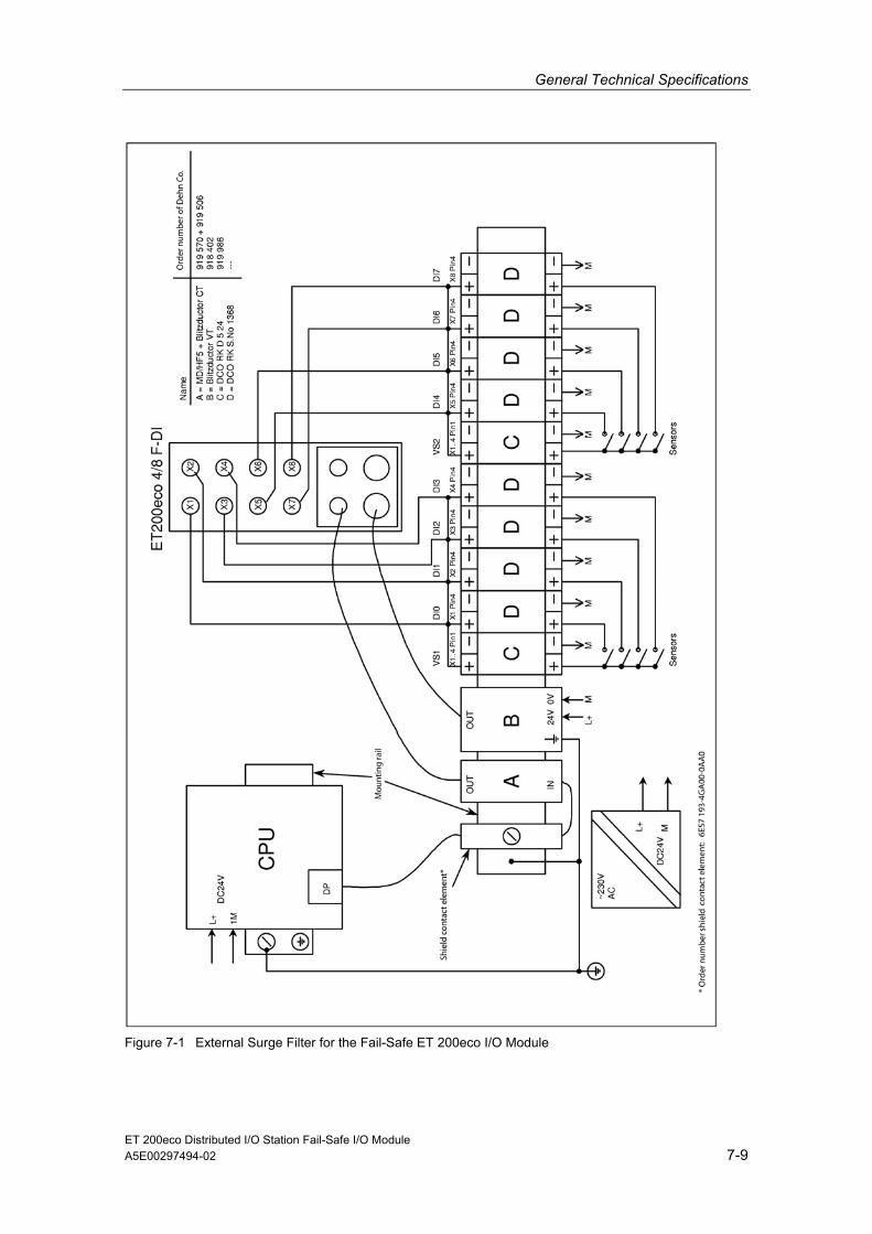
Protecting the Fail-Safe ET 200eco I/O Module from Overvoltages If your equipment makes protection from overvoltage necessary, you must use an external protective circuit (surge filter) between the load voltage power supply and the load voltage input of the I/O module to ensure surge immunity for the fail-safe ET 200eco I/O module.
Note
Lightning protection measures always require a case-by-case examination of the entire system. Nearly complete protection from overvoltages, however, can only be achieved if the entire building surroundings have been designed for overvoltage protection. In particular, this involves structural measures in the building design phase.
Therefore, for detailed information regarding overvoltage protection, we recommend that you contact your Siemens representative or a company specializing in lightning protection.
The following figure shows an example of an external surge filter for the fail-safe ET 200eco I/O module.
For additional information about surge protection for standard I/O modules, refer to the ET 200eco Distributed I/O Station manual.
General Technical Specifications
ET 200eco Distributed I/O Station Fail-Safe I/O Module A5E00297494-02 7-9
Figure 7-1 External Surge Filter for the Fail-Safe ET 200eco I/O Module

General Technical Specifications
ET 200eco Distributed I/O Station Fail-Safe I/O Module 7-10 A5E00297494-02
Sinusoidal Interferences RFI immunity according to IEC 61000-4-3:
• Electromagnetic RF field, amplitude modulated: from 80 through 2000 MHz; 10 V/m; 80 % AM (1 kHz)
• Electromagnetic RF field, pulse modulated: 900 ± 5 MHz; 10 V/m; 50 % ESD; 200 Hz repetition frequency
• GSM/ISM field interferences of different frequencies (EN 298: 1998):
System Frequency Test Level Modulation
GSM 890-915 MHz 20 V/m Pulse modulation 200Hz GSM 1710-1785 MHz 20 V/m Pulse modulation 200Hz GSM 1890 MHz 20 V/m Pulse modulation 200Hz ISM 433.05-434.79 MHz 20 V/m AM, 80% 1 kHz ISM 83,996-84,004 MHz 20 V/m AM, 80% 1 kHz ISM 167,992-168,008 MHz 20 V/m AM, 80% 1 kHz ISM 886,000-906,000 MHz 20 V/m AM, 80% 1 kHz
• HF coupling with signal lines and data lines, etc. complying with IEC 61000-4-6, high frequency, asymmetric, amplitude-modulated: from 0.15 through 80 MHz; 10 V R. M. S value, unmodulated; 80 % AM (1 kHz); 150 Ω source impedance
• ISM interferences of different frequencies (EN 298: standard 1998):
System Frequency Test Level Modulation
ISM 6,765-6,795 MHz 20 V AM, 80% 1 kHz ISM 13,553-13,567 MHz 20 V AM, 80% 1 kHz ISM 26,957-27,283 MHz 20 V AM, 80% 1 kHz ISM 40.66-40.70 MHz 20 V AM, 80% 1 kHz ISM 3,370-3,410 MHz 20 V AM, 80% 1 kHz ISM 13,533-13,533 MHz 20 V AM, 80% 1 kHz ISM 13,567-13,587 MHz 20 V AM, 80% 1 kHz

General Technical Specifications
ET 200eco Distributed I/O Station Fail-Safe I/O Module A5E00297494-02 7-11
Radio Interference Emission Emitted interference of electromagnetic fields according to EN 55011: limit value class A, group 1 (measured at a distance of 10 m).
Frequency Emitted Interference
Between 30 MHz and 230 MHz; < 40 dB (µV/m)Q Between 230 MHz and 1000 MHz; < 47 dB (µV/m)Q
Emitted interference over network AC power supply in accordance with EN 55011: Limit class A, Group 1.
Frequency Emitted Interference
Between 0.15 MHz and 0.5 MHz; < 79 dB (µV)Q, < 66 dB (µV)M Between 0.5 MHz and 5 MHz < 73 dB (µV)Q, < 60 dB (µV)M Between 5 MHz and 30 MHz < 73 dB (µV)Q, < 60 dB (µV)M
7.4 Transport and Storage Conditions
Conditions for the Fail-Safe I/O Module In terms of transport and storage conditions, the fail-safe ET 200eco I/O module is better than the requirements of IEC 61131-2. The following specifications apply to fail-safe I/O modules that are transported and stored in their original packaging.
Type of Condition Permitted Range
Free fall ≤ 1m Temperature from –40 °C through +70 °C Temperature change 20 K/h Air pressure 1080 hPA to 660 hPa
(corresponds to an altitude of -1000 m to 3500 m)
Relative humidity 5% to 95%, without condensation

General Technical Specifications
ET 200eco Distributed I/O Station Fail-Safe I/O Module 7-12 A5E00297494-02
7.5 Mechanical and Climatic Environmental Conditions
Mechanical Environmental Conditions The mechanical environmental conditions for the fail-safe I/O module are listed in the following table as sinusoidal oscillations.
Frequency Range (Hz)
Continuous Intermittent
10 ≤ f ≤ 58 0.35 mm amplitude 0.75 mm amplitude 58 ≤ f ≤ 150 5 g constant acceleration 10 g constant acceleration
Reduction of Vibration If the fail-safe I/O module is subjected to greater shock pulses or oscillation, you must take appropriate measures to reduce acceleration and amplitude.
We recommend that you mount the ET 200eco on cushioning material (for example, on a rubber-metal vibration damper).
Testing for Mechanical Environmental Conditions The following table provides information about the type and scope of testing for mechanical environmental conditions.
Condition Test Standard Comments
Oscillation Osclillation test complying with IEC 60068-2-8
Vibration method: frequency sweeps with a rate of change velocity of 1 octave per minute. 10 Hz ≤ f ≤ 58 Hz, constant amplitude 0.75 mm 58 Hz ≤ f ≤ 150 Hz, constant acceleration 10 g Vibration duration: 10 frequency sweeps per axis in each of three perpendicular axes
Shock Shock, tested to IEC 60068-2-27
Shock method: half sine Shock intensity: 30 g peak value, 18 ms duration Shock direction: 3 shocks each in +/- direction in each of three perpendicular axes
Permanent shock
Shock, tested to IEC 60068-29
Shock method: half sine Shock intensity: 25 g peak value, 6 ms duration Shock direction: 1000 shocks each in +/- direction in each of three perpendicular axes

General Technical Specifications
ET 200eco Distributed I/O Station Fail-Safe I/O Module A5E00297494-02 7-13
Climatic Environmental Conditions The fail-safe ET 200eco I/O module can be used under the following climatic environmental conditions:
Environmental Requirements
Range of Application Comments
Temperature from 0 through 55 °C All installations
Temperature change 10 K/h Relative humidity from 15 through max. 95 % no condensation Air pressure 1080 hPa to 795 Corresponds to an altitude of
-1000 m to 2000 m Pollutant concentration
SO2: < 0.5 ppm; relative humidity < 60%, no condensation H2S: < 0.1 ppm; relative humidity < 60%, no condensation
Test: 10 ppm; 4 days 1 ppm; 4 days

General Technical Specifications
ET 200eco Distributed I/O Station Fail-Safe I/O Module 7-14 A5E00297494-02
7.6 Specifications for Nominal Line Voltages, Isolation Tests, Protection Class, and Type of Protection
Nominal Line Voltages for Operation The fail-safe ET 200eco I/O module operates with rated voltage 24 VDC. The tolerance range is 20.4 V DC to 28.8 V DC.
Protection Class Protection class I in compliance with IEC 60536 (VDE 0106-1); in other words, ground terminal required on grounding screw!
Pollution degree/Overvoltage category according to IEC 61131 • Pollution degree 2
• Overvoltage category
- at UN = 24 VDC: II
Degree of protection IP 65 Degree of protection to IEC 529
• Protection against ingress of dust and full protection against touch
• Protection against a stream of water from a nozzle onto the enclosure from all directions. (The water must not have any detrimental effects.)
Degree of protection IP 66 and 67 Degree of protection to IEC 529
• Protection against ingress of dust and full protection against touch
• IP 66: Protection against heavy seas or strong water stream. (Water must not enter the enclosure in harmful quantity.)
• IP 67: Protection against water when the enclosure is immersed in water under specified pressure and time conditions. (Water must not enter the enclosure in harmful quantity.)
ET 200eco Distributed I/O Station Fail-Safe I/O Module A5E00297494-02 8-1
8 Digital F I/O Module
8.1 Introduction
Overview To connect digital sensors/encoders, you can use the fail-safe I/O module 4/8 F-DI for ET 200eco. This chapter provides the following information on the fail-safe I/O module:
• Properties and special features
• The front view, connections and the block diagram
• Wiring diagram and programmable parameters
• Diagnostic functions, including corrective measures
• Technical specifications
! Warning The safety-related characteristics in the Technical Specifications apply for a proof-test interval of 10 years and a repair time of 100 hours.
Digital F I/O Module
ET 200eco Distributed I/O Station Fail-Safe I/O Module 8-2 A5E00297494-02
8.2 Fail-Safe ET 200eco I/O Module 4/8 F-DI DC 24V PROFIsafe
Order Number 6ES7 148-3FA00-0XB0
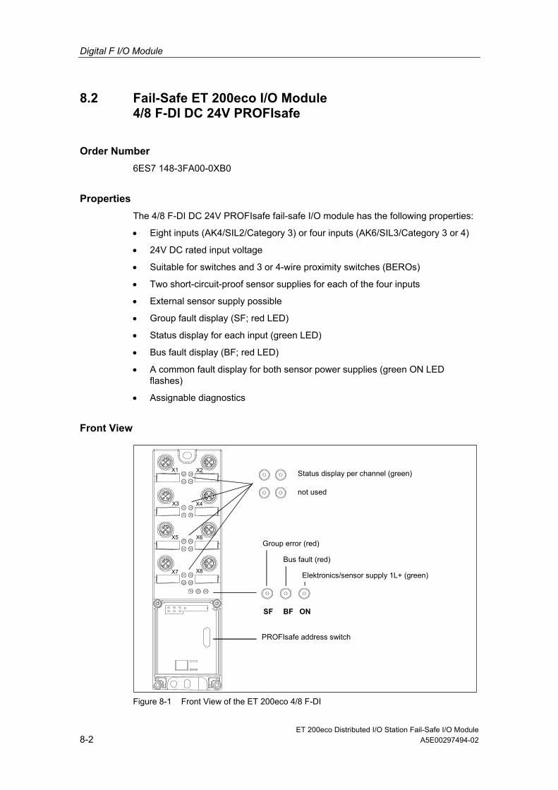
Properties The 4/8 F-DI DC 24V PROFIsafe fail-safe I/O module has the following properties:
• Eight inputs (AK4/SIL2/Category 3) or four inputs (AK6/SIL3/Category 3 or 4)
• 24V DC rated input voltage
• Suitable for switches and 3 or 4-wire proximity switches (BEROs)
• Two short-circuit-proof sensor supplies for each of the four inputs
• External sensor supply possible
• Group fault display (SF; red LED)
• Status display for each input (green LED)
• Bus fault display (BF; red LED)
• A common fault display for both sensor power supplies (green ON LED flashes)
• Assignable diagnostics
Front View
SF BF ON
PROFIsafe address switch
Elektronics/sensor supply 1L+ (green)
Bus fault (red)
Group error (red)
Status display per channel (green)
X3
X5
X7
X1 X2
X4
X6
X8
not used
Figure 8-1 Front View of the ET 200eco 4/8 F-DI

Digital F I/O Module
ET 200eco Distributed I/O Station Fail-Safe I/O Module A5E00297494-02 8-3
Terminal Assignment The following table shows the assignment of the 8 female connectors of the fail-safe ET 200eco I/O module for connecting the digital inputs.
Table 8-1 Pin Assignment of the Sockets X1 through X8 for Digital Inputs Pin Assignment of
Socket X1 Assignment of
Socket X2 Assignment of
Socket X3 Assignment of
Socket X4 View of the
Socket (from front)
1 24 V sensor power supply 1 2* Input signal
channel 4 Input signal channel 5
Input signal channel 6
Input signal channel 7
3 Ground sensor power supply (1M) 4 Input signal
channel 0 Input signal channel 1
Input signal channel 2
Input signal channel 3
5 24 V sensor power supply 2 Pin Assignment of
Socket X5 Assignment of Socket X6
Assignment of Socket X7
Assignment of Socket X8
1 24 V sensor power supply 2 2 not used 3 Ground sensor power supply (1M) 4 Input signal
channel 4 Input signal channel 5
Input signal channel 6
Input signal channel 7
5 not used
1
2
3
4
5
* Pin 2: The contact of the second channel (X5-X8) is looped through (1oo2 evaluation 1-channel sensor, application 2.1)

Digital F I/O Module
ET 200eco Distributed I/O Station Fail-Safe I/O Module 8-4 A5E00297494-02
Block Diagram
24
F address switch
M
01
32
Vs1
P
RO
FIB
US
DP
Filter logic
Status
M
P
roce
ssin
g lo
gic
SF
5
Test
BF
ON
DP address switch
Load
sup
ply
E
letro
nics
pow
er s
uppl
y
P1
P2
*
4 5
76
Vs2 *
* The representation of the NO contacts is as printed on the module. Generally, however, the sensor contacts must be NC contacts (due to safe state of the process variables).
Figure 8-2 Block Diagram of the ET 200eco 4/8 F-DI

Digital F I/O Module
ET 200eco Distributed I/O Station Fail-Safe I/O Module A5E00297494-02 8-5
Parameters in STEP 7 The following table shows the parameters that can be assigned for the ET 200eco 4/8 F-DI (see also Chapter 3).
Table 8-2 Parameters of the ET 200eco 4/8 F-DI
Parameter Range Default Setting
Type of Para-meter
Effective Range
F-Parameter: F_destination_address 1 to 1022 Assigned
automatically
Static Module
F_monitoring_time 10 to 10,000 ms 150 ms, typical
Static Module
F-Module Parameter: Input delay 3 ms/15 ms 3 ms Static Module Short-circuit test Cyclic/blocked Cyclic Static Module Channel n, n+4 Activated/deactivate
d Activated Static Channel
group Evaluation of sensors 1oo2 evaluation/
1oo1 evaluation/ 1oo2 evaluation
Static Channel group
Type of sensor interconnection
2-channel equivalent/ 1-channel/ 2-channel non-equivalent
2-channel equivalent (or 1-channel for "1oo1 evaluation“)
Static Channel group
Discrepancy Behavior Provide value 0/ Provide last valid value
"Provide 0 value"
Static Channel group
Discrepancy Time 10 to 30,000 ms 500 ms (for "provide value 0“) or 10 ms (for "1-channel“ or "provide last valid value“)
Static Channel group

Digital F I/O Module
ET 200eco Distributed I/O Station Fail-Safe I/O Module 8-6 A5E00297494-02
Input delay
Note If there is a risk of overvoltage on the lines, to avoid a safety shutdown for the fail-safe digital inputs and the sensor power supply, you must set an input delay of 15 ms.
Short-Circuit Test Parameter The cyclic short-circuit test is activated or deactivated using the short-circuit test parameter. The short-circuit test is only useful for simple switches that do not have their own power supply. The internal sensor supplies must be used whenever the short-circuit test has been activated (see also Section 8.2.1).
Response to Discrepancy Parameter As the "response to discrepancy", you set the value that is made available to the safety program in the F-CPU while there is a discrepancy between the two input channels involved; in other words, during the discrepancy time. You set the response to discrepancy as follows:
• "provide last valid value" or
• "provide 0 value"
Requirements
You have set the following:
• Sensor evaluation: "1oo2 evaluation" und
• Type of sensor: "2-channel equivalent" or "2-channel non-equivalent"
"Provide Last Valid Value "
The last valid value (old value) before discrepancy occurs is made available in the safety program in F-CPU as soon as a discrepancy is determined between the signals of the affected input channels. This value remains available until the discrepancy disappears or until the discrepancy time expires and a discrepancy error is detected. The sensor-actuator response time is extended according to the this time.
As a result, the discrepancy time of sensors connected over two channels must be set for fast responses to short response times. It makes no sense, for example, if sensors connected over two channels with a discrepancy time of 500 ms trigger a time-critical shutdown. In the worst case, the sensor-actuator response time is extended by an amount approximately equal to the discrepancy time:
• For this reason, position the sensor in the process in such a way to minimize discrepancy.
• You should then select the shortest possible discrepancy time, which, on the other hand, also provides adequate reserves against the erroneous triggering of discrepancy errors.
Digital F I/O Module
ET 200eco Distributed I/O Station Fail-Safe I/O Module A5E00297494-02 8-7
"Provide 0 value"
The value "0" is immediately made available to the safety program in the F-CPU as soon as a discrepancy is detected between the signals of the two affected input channels.
If you assigned the parameter "Provide 0 value“, the sensor-actuator response time will not be affected by the discrepancy time.
Discrepancy Time Here, you can specify the discrepancy time for each pair of channels. The value entered is rounded to multiples of 10 ms.
Requirements
You have set the following:
• Sensor evaluation: "1oo2 evaluation" und
• Type of sensor: "2-channel equivalent" or "2-channel non-equivalent"
Discrepancy Analysis and Discrepancy Time
If you use a 2-channel, one non-equivalent, or two 1-channel sensors, that measure the same physical process variable, the sensors will respond with a slight time delay among each other due to the limited accuracy of the arrangement.
Discrepancy analysis for equivalence or nonequivalence is used for fail-safe inputs to determine faults based on the time characteristic of two signals with the same functionality. Discrepancy analysis is initiated when different levels are detected for two associated input signals (for nonequivalence testing, when the same levels are detected). The signals are checked to establish whether the difference (when checking for non-quality: the match) has disappeared following a selectable time known as the discrepancy time. If not, this means that a discrepancy error exists.
The most cases, the discrepancy time is started but is not elapse fully since the signal differences disappear after a short time.
Select a discrepancy time that is long enough so that when no error has occurred, the difference between two signals (the match between two signals when checking for non-equality) disappears before the discrepancy time elapses.
Response While the Discrepancy Time Is Running
While the discrepancy time is running internally on the module, either the last valid value or "0“ is provided for the safety program on the F-CPU by the input channels involved depending on the parameter settings for the response to discrepancy.
Response after the Discrepancy Time Elapses
If the input signals do not match after the selected discrepancy time has elapsed (when checking for non-equivalence) for example due to a break in the sensor wire, a discrepancy error is detected and the "discrepancy error" diagnostic message is generated in the diagnostic buffer of the F-I/O module indicating the faulty channels.

Digital F I/O Module
ET 200eco Distributed I/O Station Fail-Safe I/O Module 8-8 A5E00297494-02
8.2.1 Applications of the ET 200eco 4/8 F-DI
Selecting the Application The following figure provides information to help you select the application that corresponds to your fail-safe requirements. The following chapters provide instructions for each application on wiring the fail-safe I/O module and requirements for specific parameter settings in STEP 7.
Requiredsafety class?
Use Cases 1 to 3
21 See
Section 8.2.3See
Section 8.2.2
AK 6/SIL3/Category 3AK4/SIL 2/Category 3 AK6/SIL3/Category 4
3See
Section 8.2.4
Figure 8-3 Selecting a Application - ET 200eco 4/8 F-DI
! Warning The achievable safety class is dependent on the quality of the sensor and the magnitude of the proof-test interval in accordance with IEC 61508 (interval for external function test). If the quality of the sensor is lower than the quality stipulated in the required safety class, the sensor must be applied redundantly with a two-channel connection.

Digital F I/O Module
ET 200eco Distributed I/O Station Fail-Safe I/O Module A5E00297494-02 8-9
Conditions for Achieving AK/SIL/Category The conditions for achieving the respective safety requirements are presented in the following table.
Table 8-3 ET 200eco 4/8 F-DI: Conditions for Achieving the AK/SIL/Category
Application Sensor Evaluation of sensors
Sensor power supply
Achievable AK/SIL/
Category
Internal, with short-circuit test
Internal, without short-circuit test
1 1-channel 1oo1
External
4/2/3
2.1 Internal, with short-circuit test
Internal, without short-circuit test
1-channel 1oo2
External 2.2 Internal, without
short-circuit test
2-channel equivalent
1oo2
External 2.3 Internal, without
short-circuit test
2-channel non-equivalent
1oo2
External
6/3/3
3.1 2-channel equivalent
3.2 2-channel non-equivalent
1oo2 Internal, with short-circuit test
6/3/4
Note
You can operate the various inputs of a fail-safe I/O module simultaneously in AK4/SIL2/Category 3 and in AK6/SIL3/Category 3 or 4. You only need to interconnect and assign parameters for the inputs as shown in the following sections.
Sensor Requirements When using sensors for safety-related applications, please note the information in Section 5.5 "Requirements for Sensors“.

Digital F I/O Module
ET 200eco Distributed I/O Station Fail-Safe I/O Module 8-10 A5E00297494-02
8.2.2 Application 1: Safety Mode AK4/SIL2/Category 3
Sensor Supply The ET 200eco 4/8 F-DI provides sensor supply Vs1 for inputs 0 to 3 and sensor supply Vs2 for inputs 4 to 7. The sensor supply can be provided internally or externally.
Wiring Diagram for Application 1 – Connecting one sensor to one channel One 1-channel sensor (1oo1 evaluation) ) is connected for each process signal.
8 F-DI
ET 200eco 4/8 F-DI
L+ M DI0 DI1 DI2 DI3 DI4 DI5 DI6 DI7 Vs1 Vs2
L+ M
S0 S1 S2 S3 S4 S5 S6 S7
Figure 8-4 Wiring Diagram ET 200eco 4/8 F-DI – One 1-channel Sensor Connected, Internal Sensor Supply
8 F-DI
ET 200eco 4/8 F-DI
L+ M DI0 DI1 DI2 DI3 DI4 DI5 DI6 DI7Vs1 Vs2
L+ M
S0 S1 S2 S3 S4 S5 S6 S7
Figure 8-5 Wiring Diagram ET 200eco 4/8 F-DI – One 1-channel Sensor Connected, External Sensor Supply

Digital F I/O Module
ET 200eco Distributed I/O Station Fail-Safe I/O Module A5E00297494-02 8-11
Assignable Parameters for Application 1 Set the parameter "Evaluation of sensor“ to "1oo1 evaluation“ for the respective input.
You can activate or deactivate the "short-circuit test" parameter. However, you must deactivate the short-circuit test as soon as one or more fail-safe digital inputs are externally supplied. Otherwise the diagnostic "short-circuit“ could be signaled when applicable..
Special Features of Error Detection (Application 1) The following table presents error detection according to the sensor supply and the parameter assignment for the short-circuit test:
Table 8-4 ET 200eco 4/8 F-DI: Fault Detection (Application 1)
Fault detection when ... Example of Error Internal sensor
supply and activated short-
circuit test
Internal sensor supply and
deactivated short-circuit Test
External Sensor Supply
Short circuit in DI 0 with DI 1
No No No
Short circuit in DI 0 with DI 4
Yes* No No
P-short circuit in DI 0 Yes No No M-short circuit in DI 0 Yes* Yes* No Discrepancy error - - - P-short current in sensor supply 1
Yes No No
M-short circuit in sensor supply 1 or GV1 defective
Yes Yes Yes
Short circuit in sensor supply 1 with sensor supply 2
Yes No No
Error in read/test circuit Yes Yes Yes Supply voltage fault Yes Yes Yes
* Error is detected only in case of signal corruption. That is, the signal read differs from the sensor signal. If there is no signal corruption with respect to the sensor signal, error detection is not possible and is not required from a safety standpoint.

Digital F I/O Module
ET 200eco Distributed I/O Station Fail-Safe I/O Module 8-12 A5E00297494-02
8.2.3 Application 2: Safety Mode AK6/SIL3/Category 3
Assigning Inputs to Each Other The ET 200eco 4/8 F-DI has 8 fail-safe inputs DI 0 to DI 7 (SIL2). Two inputs each can be used as one input (SIL3) The following assignment applies:
• DI 0 with DI 4
• DI 1 with DI 5
• DI 2 with DI 6
• DI 3 with DI 7
Sensor Supply The ET 200eco 4/8 F-DI provides sensor supply Vs1 for inputs 0 to 3 and sensor supply Vs2 for inputs 4 to 7. The sensor power supply can be provided internally or externally.
Wiring Diagram for Application 2.1 – Connecting one channel of one sensor to two inputs
One channel of a sensor is connected to two inputs of the fail-safe I/O module for each process signal (1oo2 evaluation).
Note
If the voltage is supplied to the sensor by the fail-safe I/O module, you must use the internal sensor supply Vs1. Connection to Vs2 is not possible.

Digital F I/O Module
ET 200eco Distributed I/O Station Fail-Safe I/O Module A5E00297494-02 8-13
4 F-DI
ET 200eco 4/8 F-DI
L+ M DI0 DI1 DI2 DI3 DI4 DI5 DI6 DI7Vs1 Vs2
L+ M
S0
S1
S2
S3
Figure 8-6 Wiring Diagram ET 200eco 4/8 F-DI – One Channel of a Sensor Connected to Two Inputs, Internal Power Supply
4 F-DI
ET 200eco 4/8 F-DI
L+ M DI0 DI1 DI2 DI3 DI4 DI5 DI6 DI7Vs1 Vs2
L+ M
S0
S1
S2
S3
Figure 8-7 Wiring Diagram ET 200eco 4/8 F-DI – One Channel of a Sensor Connected to Two Inputs, External Power Supply
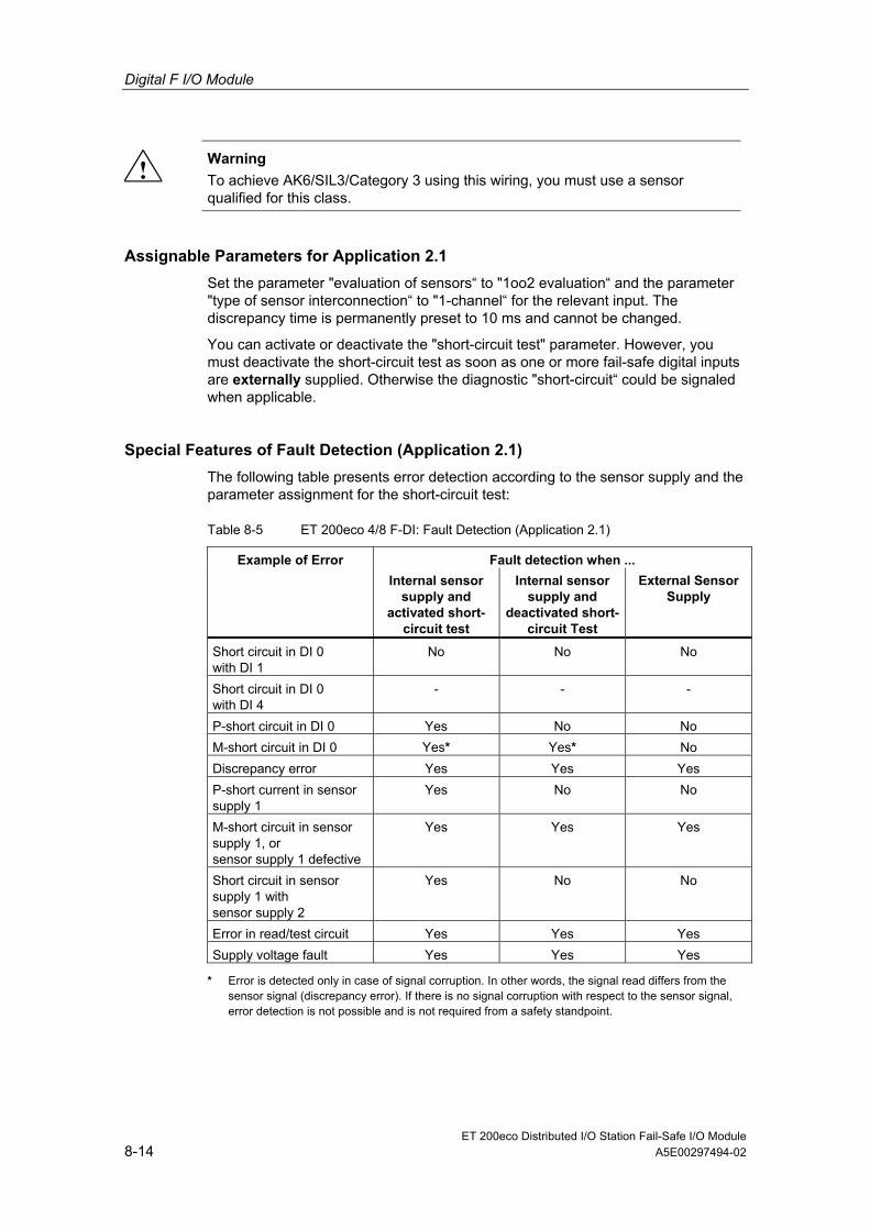
Digital F I/O Module
ET 200eco Distributed I/O Station Fail-Safe I/O Module 8-14 A5E00297494-02
! Warning To achieve AK6/SIL3/Category 3 using this wiring, you must use a sensor qualified for this class.
Assignable Parameters for Application 2.1 Set the parameter "evaluation of sensors“ to "1oo2 evaluation“ and the parameter "type of sensor interconnection“ to "1-channel“ for the relevant input. The discrepancy time is permanently preset to 10 ms and cannot be changed.
You can activate or deactivate the "short-circuit test" parameter. However, you must deactivate the short-circuit test as soon as one or more fail-safe digital inputs are externally supplied. Otherwise the diagnostic "short-circuit“ could be signaled when applicable.
Special Features of Fault Detection (Application 2.1) The following table presents error detection according to the sensor supply and the parameter assignment for the short-circuit test:
Table 8-5 ET 200eco 4/8 F-DI: Fault Detection (Application 2.1)
Fault detection when ... Example of Error Internal sensor
supply and activated short-
circuit test
Internal sensor supply and
deactivated short-circuit Test
External Sensor Supply
Short circuit in DI 0 with DI 1
No No No
Short circuit in DI 0 with DI 4
- - -
P-short circuit in DI 0 Yes No No M-short circuit in DI 0 Yes* Yes* No Discrepancy error Yes Yes Yes P-short current in sensor supply 1
Yes No No
M-short circuit in sensor supply 1, or sensor supply 1 defective
Yes Yes Yes
Short circuit in sensor supply 1 with sensor supply 2
Yes No No
Error in read/test circuit Yes Yes Yes Supply voltage fault Yes Yes Yes
* Error is detected only in case of signal corruption. In other words, the signal read differs from the sensor signal (discrepancy error). If there is no signal corruption with respect to the sensor signal, error detection is not possible and is not required from a safety standpoint.

Digital F I/O Module
ET 200eco Distributed I/O Station Fail-Safe I/O Module A5E00297494-02 8-15
Wiring Diagram for Application 2.2 – Connecting a two-channel sensor to two channels
Two channels of a 2-channel sensor are connected to two inputs of the fail-safe I/O module for each process signal (1oo2 evaluation).
4 F-DI
ET 200eco 4/8 F-DI
L+ M DI0 DI1 DI2 DI3 DI4 DI5 DI6 DI7 Vs1 Vs2
L+ M
S0
S1
S2
S3
Sensor contacts are mechanically coupled.
Figure 8-8 Wiring Diagram ET 200eco 4/8 F-DI – Two Channels of a 2-channel Sensor Connected, Internal Sensor Supply
4 F-DI
ET 200eco 4/8 F-DI
L+ M DI0 DI1 DI2 DI3 DI4 DI5 DI6 DI7 Vs1 Vs2
L+ M
S0
S1
S2
S3
Sensor contacts are mechanically coupled.
Figure 8-9 Wiring Diagram ET 200eco 4/8 F-DI – Two Channels of a 2-channel Sensor Connected, External Sensor Supply

Digital F I/O Module
ET 200eco Distributed I/O Station Fail-Safe I/O Module 8-16 A5E00297494-02
Wiring Diagram for Application 2.2 – Connecting two channels of two 1-channel sensors
Two channels of two 1-channel sensors are connected to two inputs of the fail-safe I/O module for each process signal (1oo2 evaluation). The sensors can also be supplied via an external sensor supply.
4 F-DI
ET 200eco 4/8 F-DI
L+ M DI0 DI1 DI2 DI3 DI4 DI5 DI6 DI7 Vs1 Vs2
L+ M
S0
S1
S2
S3
Acquisition of the same process variable with mechanically separate sensors.
Figure 8-10 Wiring Diagram ET 200eco 4/8 F-DI – Two Channels of Two 1-channel Sensors Connected, Internal Sensor Supply
! Warning To achieve AK6/SIL3/Category 3 using this wiring, you must use a sensor qualified for this class.
Assignable Parameters for Application 2.2 Set the parameter "evaluation of sensors“ to "1oo2 evaluation“ and the parameter "type of sensor interconnection“ to "2-channel equivalent“ for the relevant input. Deactivate the parameter "short-circuit test.“
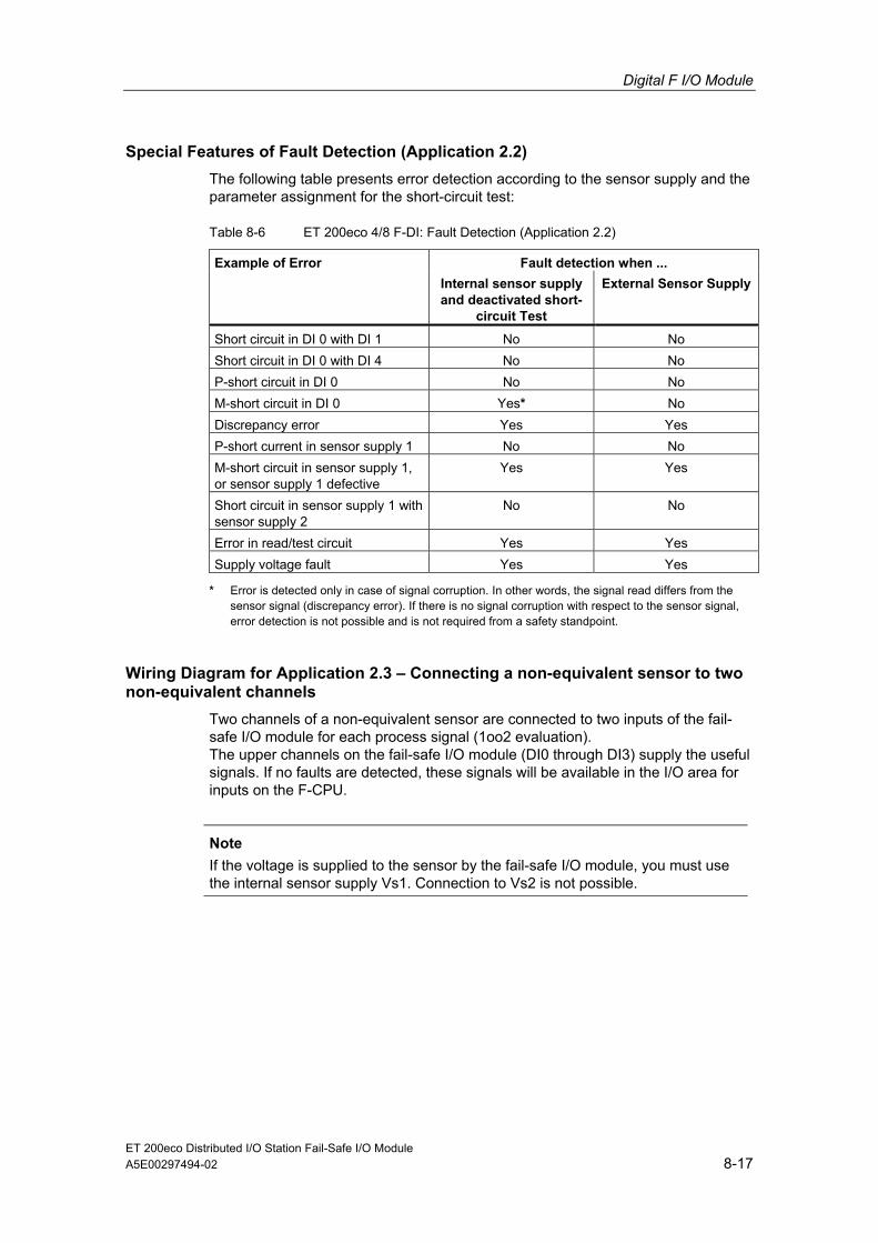
Digital F I/O Module
ET 200eco Distributed I/O Station Fail-Safe I/O Module A5E00297494-02 8-17
Special Features of Fault Detection (Application 2.2) The following table presents error detection according to the sensor supply and the parameter assignment for the short-circuit test:
Table 8-6 ET 200eco 4/8 F-DI: Fault Detection (Application 2.2)
Fault detection when ... Example of Error Internal sensor supply and deactivated short-
circuit Test
External Sensor Supply
Short circuit in DI 0 with DI 1 No No Short circuit in DI 0 with DI 4 No No P-short circuit in DI 0 No No M-short circuit in DI 0 Yes* No Discrepancy error Yes Yes P-short current in sensor supply 1 No No M-short circuit in sensor supply 1, or sensor supply 1 defective
Yes Yes
Short circuit in sensor supply 1 with sensor supply 2
No No
Error in read/test circuit Yes Yes Supply voltage fault Yes Yes
* Error is detected only in case of signal corruption. In other words, the signal read differs from the sensor signal (discrepancy error). If there is no signal corruption with respect to the sensor signal, error detection is not possible and is not required from a safety standpoint.
Wiring Diagram for Application 2.3 – Connecting a non-equivalent sensor to two non-equivalent channels
Two channels of a non-equivalent sensor are connected to two inputs of the fail-safe I/O module for each process signal (1oo2 evaluation). The upper channels on the fail-safe I/O module (DI0 through DI3) supply the useful signals. If no faults are detected, these signals will be available in the I/O area for inputs on the F-CPU.
Note
If the voltage is supplied to the sensor by the fail-safe I/O module, you must use the internal sensor supply Vs1. Connection to Vs2 is not possible.

Digital F I/O Module
ET 200eco Distributed I/O Station Fail-Safe I/O Module 8-18 A5E00297494-02
4 F-DI
ET 200eco 4/8 F-DI
L+ M DI0 * DI1 * DI2 * DI3 * DI4 DI5 DI6 DI7 Vs1 Vs2
L+ M
S0
S1
S2
S3
* The upper channels on the fail-safe I/O module provide the useful signals.
Figure 8-11 Wiring Diagram ET 200eco 4/8 F-DI – Two Channels of a Non-equivalent Sensor Connected (for non-equivalence), Internal Sensor Supply
4 F-DI
ET 200eco 4/8 F-DI
L+ M DI0 * DI1 * DI2 * DI3 * DI4 DI5 DI6 DI7 Vs1 Vs2
L+ M
S0
S1
S2
S3
* The upper channels on the fail-safe I/O module provide the useful signals.
Figure 8-12 Wiring Diagram ET 200eco 4/8 F-DI – Two Channels of a Non-equivalent Sensor Connected (for non-equivalence), External Sensor Supply

Digital F I/O Module
ET 200eco Distributed I/O Station Fail-Safe I/O Module A5E00297494-02 8-19
Wiring Diagram for Application 2.3 – Connecting two one-channel sensors to two non-equivalent channels
Two channels of two 1-channel sensors are connected non-equivalent to two inputs of the F-I/O module for each process signal (1oo2 evaluation). The sensors can also be supplied via an external sensor supply.
4 F-DI
ET 200eco 4/8 F-DI
L+ M DI0 * DI1 * DI2 * DI3 * DI4 DI5 DI6 DI7 Vs1 Vs2
L+ M
S0
S1
S2
S3
* The upper channels on the fail-safe I/O module provide the useful signals. Acquisition of the same process variable with mechanically separate
Figure 8-13 Wiring Diagram ET 200eco 4/8 F-DI – Two Channels of Two 1-channel Sensors Connected (for non-equivalence), Internal Sensor Supply
! Warning To achieve AK6/SIL3/Category 3 using this wiring, you must use a sensor qualified for this class.
Assignable Parameters for Application 2.3 Set the parameter "evaluation of sensors“ to "1oo2 evaluation“ and the parameter "type of sensor interconnection“ to "2-channel non-equivalent“ for the relevant input. Deactivate the parameter "short-circuit test.“

Digital F I/O Module
ET 200eco Distributed I/O Station Fail-Safe I/O Module 8-20 A5E00297494-02
Special Features of Fault Detection (Application 2.3) The following table shows fault detection depending on the sensor power supply and the parameter assignment for the short-circuit test:
Table 8-7 ET 200eco 4/8 F-DI: Fault Detection (Application 2.3)
Fault detection when ... Example of Error Internal sensor supply and deactivated short-
circuit Test
External Sensor Supply
Short circuit in DI 0 with DI 1 No No Short circuit in DI 0 with DI 4 Yes Yes P-short circuit in DI 0 No No M-short circuit in DI 0 No No Discrepancy error Yes Yes P-short current in sensor supply 1 No No M-short circuit in sensor supply 1, or sensor supply 1 defective
Yes Yes
Short circuit in sensor supply 1 with sensor supply 2
No No
Error in read/test circuit Yes Yes Supply voltage fault Yes Yes
* Error is detected only in case of signal corruption. In other words, the signal read differs from the sensor signal (discrepancy error). If there is no signal corruption with respect to the sensor signal, error detection is not possible and is not required from a safety standpoint.

Digital F I/O Module
ET 200eco Distributed I/O Station Fail-Safe I/O Module A5E00297494-02 8-21
8.2.4 Application 3: Safety Mode AK6/SIL3/Category 4
Assigning Inputs to Each Other The ET 200eco 4/8 F-DI has 8 fail-safe inputs DI 0 to DI 7 (SIL2). Two inputs each can be used as one input (SIL3) The following assignment applies:
• DI 0 with DI 4
• DI 1 with DI 5
• DI 2 with DI 6
• DI 3 with DI 7
Sensor Supply The ET 200eco 4/8 F-DI provides sensor supply Vs1 for inputs 0 to 3 and sensor supply Vs2 for inputs 4 to 7. The sensor must be supplied internally.

Digital F I/O Module
ET 200eco Distributed I/O Station Fail-Safe I/O Module 8-22 A5E00297494-02
Wiring Diagram for Application 3.1 – Connecting a two-channel sensor to two channels
Two channels of a 2-channel sensor are connected to two inputs of the fail-safe I/O module for each process signal (1oo2 evaluation).
DI3
4 F-DI
ET 200eco 4/8 F-DI
L+ M DI0 DI1 DI2 DI4 DI5 DI6 DI7 Vs1 Vs2
L+ M
S0
S1
S2
S3
Sensor contacts are mechanically coupled.
Figure 8-14 Wiring Diagram ET 200eco 4/8 F-DI – Two Channels of a 2-channel Sensor Connected, Internal Sensor Supply
As an alternative, you can connect two 1-channel sensors (see Figure 8-10). In this case, the same process variable is acquired with two mechanically separate sensors.
! Warning To achieve AK6/SIL3/Category 4 using this wiring, you must use a sensor qualified for this class.
Assignable Parameters for Application 3.1 Set the parameter "evaluation of sensors“ to "1oo2 evaluation“ and the parameter "type of sensor interconnection“ to "2-channel equivalent“ for the relevant input. Deactivate the parameter "short-circuit test.“

Digital F I/O Module
ET 200eco Distributed I/O Station Fail-Safe I/O Module A5E00297494-02 8-23
Wiring Diagram for Application 3.2 – Connecting a non-equivalent sensor to two non-equivalent channels
Two channels of a non-equivalent sensor are connected to two inputs of the fail-safe I/O module for each process signal (1oo2 evaluation). The upper channels on the fail-safe I/O module (DI0 through DI3) supply the useful signals. If no faults are detected, these signals will be available in the I/O area for inputs on the F-CPU.
Note
You must use the internal sensor supply Vs1 to supply voltage to the sensor. Connection to Vs2 is not possible.
4 F-DI
ET 200eco 4/8 F-DI
L+ M DI0 * DI1 * DI2 * DI3 * DI4 DI5 DI6 DI7 Vs1 Vs2
L+ M
S0
S1
S2
S3
* The upper channels on the fail-safe DI I/O module provide the useful signals.
Figure 8-15 Wiring Diagram ET 200eco 4/8 F-DI – Two Channels of a Non-equivalent Sensor Connected (for non-equivalence), Internal Sensor Supply
As an alternative, you can connect two 1-channel sensors non-equivalent (see Figure 8-13). In this case, the same process variable is acquired with two mechanically separate sensors.
! Warning To achieve AK6/SIL3/Category 4 using this wiring, you must use a sensor qualified for this class.

Digital F I/O Module
ET 200eco Distributed I/O Station Fail-Safe I/O Module 8-24 A5E00297494-02
Assignable Parameters for Application 3.2 Set the parameter "evaluation of sensors“ to "1oo2 evaluation“ and the parameter "type of sensor interconnection“ to "2-channel non-equivalent“ for the relevant input. Deactivate the parameter "short-circuit test.“
Special Features of Fault Detection (Application 3.1 and 3.2) The following table presents error detection according to the sensor supply and the parameter assignment for the short-circuit test:
Table 8-8 ET 200eco 4/8 F-DI: Fault Detection (Applications 3.1 and 3.2)
Fault detection with internal sensor power supply and activated short-circuit test for...
Example of Error
Sensor 2-channel equivalent
Sensor 2-channel non-equivalent
Short circuit in DI 0 with DI 1 No No Short circuit in DI 0 with DI 4 Yes* Yes P-short circuit in DI 0 Yes Yes M-short circuit in DI 0 Yes* Yes* Discrepancy error Yes Yes P-short current in sensor supply 1 Yes Yes M-short circuit in sensor supply 1, or sensor supply 1 defective
Yes Yes
Short circuit in sensor supply 1 with sensor supply 2
Yes Yes
Error in read/test circuit Yes Yes Supply voltage fault Yes Yes
* Error is detected only in case of signal corruption. In other words, the signal read differs from the sensor signal (discrepancy error). If there is no signal corruption with respect to the sensor signal, error detection is not possible and is not required from a safety standpoint.
Requirements for Machine Protection Applications with Category 4 The requirements for machine protection applications with Category 4 are:
• Wiring between sensors and the automation system and between the automation system and the actuators must be state-of-the-art and must comply with standards for preventing short circuits.
• All short circuits detected in the table above are detected. In this case, it is sufficient to detect one short circuit, because it required two faults to be generated (both of the short-circuited signal cables indicate an isolation fault). Consequently, a multiple short-circuit analysis is not required.
Methods for detecting all short circuits are permissible even if no individual short circuits are detected, provided they do one of the following:
• Do not cause corruption of read signals compared to sensor signals
• Cause corruption of read signals compared to sensor signals, but in the direction that ensures safety

Digital F I/O Module
ET 200eco Distributed I/O Station Fail-Safe I/O Module A5E00297494-02 8-25
8.2.5 Diagnostic Functions of the ET 200eco 4/8 F-DI
Reaction to Sensor Power Supply Faults Faults in the sensor power supplies Vs1 and Vs2 of the ET 200eco 4/8 F-DI are indicated by the ON LED flashing on the fail-safe I/O module. This information is also provided in the I/O module (diagnostic entry).
• Fail-safe system S7 Distributed Safety: The entire fail-safe I/O module is passivated.
• Fail-safe system S7 F/FH Systems: The channels of the sensor power supply affected are passivated.
The SF LED is lit. When the fault is cleared, the LED flashes. After acknowledging the fault in the safety program, the SF LED goes off again.
See also Chapter 6.
Diagnostic Functions The following table provides you with an overview of the diagnostic functions of the ET 200eco 4/8 F-DI. Diagnostic functions are assigned either to one channel or to the entire fail-safe I/O module.
Table 8-9 Diagnostic Functions of the ET 200eco 4/8 F-DI
Diagnostic Function* Fault Number
LED Signaled in Application
Effective Range of Diagnostics
Assign-able Para-meter?
Short circuit 1H SF 1, 2, 3 Channel Yes Overtemperature 5H SF 1, 2, 3 Module No Internal error 9H SF 1, 2, 3 Module No Parameter assignment error 10H SF 1, 2, 3 Module No Sensor or load voltage fault 11H SF 1, 2, 3 Module No Communication error 13H SF 1, 2, 3 Module No Discrepancy error (1oo2 evaluation)
19H SF 2,3 Channel No
* Specifically for fail-safe I/O modules; display in STEP 7, see Table 6-1.
Note
If you have activated the short-circuit test for the fail-safe I/O module in STEP 7 and are using only one of the two internal sensor supplies of the module (Vs1 or Vs2), a channel P-short circuit is then detected for each of the four channels with a sensor supply that is not used. Four "short-circuit" diagnostic functions are generated in the diagnostic buffer of the fail-safe I/O module.

Digital F I/O Module
ET 200eco Distributed I/O Station Fail-Safe I/O Module 8-26 A5E00297494-02
Special Features for Error Detection Detection of some errors (such as short circuits or discrepancy errors) is dependent on the application, wiring, and parameter assignment of the short-circuit test. For this reason, tables on error detection are included in Sections 8.2.2 through 8.2.4 for the specific applications.
Causes of Errors and Corrective Measures The following table presents the possible causes of errors and corrective measures for the individual diagnostic messages of the ET 200eco 4/8 F-DI.
Table 8-10 Diagnostic Messages of the ET 200eco 4/8 F-DI, Causes of Errors and Corrective Measures
Diagnostic Message
Possible Causes Remedies
Short circuit in the sensor Cross circuit in the sensor
Eliminate short circuit/cross circuit Short circuit
Internal error Replace module Overtempera-ture
Temperature limit in the module housing is exceeded causing module to be deactivated
Check ambient temperature, and check whether permissible output current of the sensor supply is exceeded for the ambient temperature After clearing the problem, you must turn the power off and on again
Internal error Internal module fault has occurred Replace module Inserted module does not match configuration Faulty parameter assignment
Correct the configuration (compare actual and preset configuration), and check communication paths Correct the parameter assignment
Parameter assignment error
PROFIsafe address set incorrectly in the fail-safe I/O module
Check whether the PROFIsafe address on the module matches the configuration in STEP 7 HW Config
External auxiliary power supply missing
No supply voltage or supply voltage is too low
Check module for correct contact After clearing the problem, you must turn the power off and on again
Error in communication between F-CPU and module due to defective PROFIBUS connection or higher than permissible EMI, for example
Check the PROFIBUS connection Eliminate the interference
PROFIsafe monitoring time set too low
Set a higher value for the "F-moni-toring time“ parameter for the module in STEP 7 HW Config
Communi-cation error
Configuration of the fail-safe I/O module does not match safety program
Recompile the safety program; then download the configuration and safety program to the F-CPU again

Digital F I/O Module
ET 200eco Distributed I/O Station Fail-Safe I/O Module A5E00297494-02 8-27
Diagnostic Message
Possible Causes Remedies
Faulty process signal Defective sensor
Check process signal, replace sensor if necessary
Short circuit between unconnected sensor cable and the sensor supply cable
Eliminate short circuit
Wire break in connected sensor cable or the sensor supply cable
Eliminate broken wire
Assigned discrepancy time too short
Check the assigned discrepancy time
Discrepancy error (1oo2 evaluation)
After eliminating the problem, the fail-safe I/O module must be re-integrated in the safety program.
For more detailed information on passivation and reintegration of F-I/O, refer to Chapter 6 and the S7 Distributed Safety, Configuration and Programming manual or Programmable Controllers S7 F/FH Systems.
Generally Applicable Information on Diagnostics For general information on diagnostics (for example on reading out diagnostic functions, passivating channels), refer to Chapter 6.

Digital F I/O Module
ET 200eco Distributed I/O Station Fail-Safe I/O Module 8-28 A5E00297494-02
8.2.6 Technical Specifications of the ET 200eco 4/8 F-DI
Technical Specifications
Dimensions and Weight Dimensions W x H x D (mm) 60 x 210 x 28 Weight Approx. 220 g Module-Specific Specifications Number of inputs Can be selected per input • 1-channel 8, maximum • 2-channel 4, maximum Assigned address area • In the I/O area for inputs 6 Byte • In the I/O area for outputs 4 Byte Length of cable • Unshielded 30 m, maximum Maximum achievable safety class 1-channel 2-channel • In Accordance with IEC 61508 SIL2 SIL3 • In accordance with DIN VDE 0801 AK4 AK6 • In accordance with EN 954 Category 3 Category 4 Safety-related characteristics SIL2 SIL3 • Low demand mode (average probability
of failure on demand) << 1.00 E-03 << 1.00 E-05
• High demand/continuous mode (probability of a dangerous failure per hour)
<< 1.00 E-08
<< 1.00 E-10
Voltages, Currents, Potentials Rated supply voltage L+ 24V DC • Permitted Range 20.4 V to 28.8 V • Power loss ride-through of L+ None • Power loss ride-through of internal P5 5 ms • Reverse polarity protection No Number of simultaneously controllable inputs
8
• All installations - Up to 55°C 8 Electrical isolation • Between channels and backplane bus Yes • Between channels and power supply No • Between channels No • Between channels/power supply and
shield Yes
Permissible potential difference between • Shield and ET 200eco bus connection 75 VDC/60 VAC • Shield and I/O 75 VDC/60 VAC • ET 200eco bus connection and I/O 75 VDC/60 VAC

Digital F I/O Module
ET 200eco Distributed I/O Station Fail-Safe I/O Module A5E00297494-02 8-29
Technical Specifications
Isolation in the type test tested with • Shield and ET 200eco bus connection 350 VAC/1 min • Shield and I/O 350 VAC/1 min • ET 200eco bus connection and I/O 350 VAC/1 min Current consumption • From load voltage L+ (without load) 100 mA, typical Power loss of the fail-safe I/O module 3 W, typical Status, Interrupts, Diagnostics Status display Inputs Green LED per channel Sensor supply Green LED for both channels Interrupts Diagnostic Interrupt "ON" Diagnostic functions • Group error display Red LED (SF) • Bus fault display Red LED (BF) • Diagnostic information can be displayed Possible Sensor Supply Outputs Number of outputs 2 Output voltage • Loaded Minimum L+ (-1.5 V) Output current • Rated value 300 mA • Permitted Range 0 mA to 300 mA Permissible aggregate current of outputs 600 mA Short-circuit protection Yes, electronic • Operating value 0.7 A to 1.8 A Data for Selecting a Sensor** Input voltage • Rated value 24V DC • For "1“ signal 15 V to 30 V • For "0“ signal -30 V to 5 V Input current • For "1“ signal 3,7 mA, typical

Digital F I/O Module
ET 200eco Distributed I/O Station Fail-Safe I/O Module 8-30 A5E00297494-02
Technical Specifications Input delay* Assignable
(for all inputs together) • For "0“ after "1“ Typically 3 ms (2.6 ms to 3.4 ms) Typically 15 ms (13 ms to 17 ms) • For "1“ after "0“ Typically 3 ms (2.6 ms to 3.4 ms) Typically 15 ms (13 ms to 17 ms) Input characteristic In accordance with IEC 1131, Type 1 Connection of 2-wire proximity switch Not possible • Permissible quiescent current 0.6 mA, maximum Time, Frequency Internal preparation times See Chapter 10 Acknowledgment time in safety mode • Short-circuit test activated
at input delay of 3 ms: at input delay of 15 ms:
min. 13 ms / max. 26 ms min. 13 ms / max. 22 ms
• Short-circuit test deactivated 13 ms minimum/22 ms maximum Minimum sensor signal duration See Table 5-1 Protection against Overvoltage Protection of supply voltage L+ from surge in accordance with IEC 61000-4-5 with external protection elements only
• Symmetrical (L+ to M) + 1 kV; 1.2/50 µs • Asymmetrical
(L+ to PE, M to PE) + 2 kV; 1.2/50 µs
Protection of inputs and outputs from surge stressing in accordance with IEC 61000-4-5 with external protection elements only
• Symmetrical (Vs, DI to M) + 1 kV; 1.2/50 µs • Asymmetrical
(Vs, DI to PE, M to PE) + 1 kV; 1.2/50 µs
* If there is a risk of overvoltage on the lines, to avoid a safety shutdown of the fail-safe digital inputs and the sensor power supply, you must set an input delay of 15 ms (see Section 7.3).
* For requirements for sensors, refer to Section 5.5

ET 200eco Distributed I/O Station Fail-Safe I/O Module A5E00297494-02 9-1
9 Accessories and Order Numbers
Accessories and Order Numbers Below, you will find the order numbers of the ET 200eco components you require to use the fail-safe ET 200eco I/O module. The standard accessories for I/O modules, terminal block ECOFAST and terminal block M12, 7/8" can also be used with the fail-safe ET 200eco I/O module (see ET 200eco Distributed I/O Station) manual.
Components of the Fail-Safe ET 200eco I/O Module Component Order Number
4/8 F-DI DC24V PROFIsafe digital I/O module 6ES7 148-3FA00-0XB0 Terminal block M12, 7/8" 6ES7 194-3AA00-0BA0 Terminal block ECOFAST 6ES7 194-3AA00-0AA0

Accessories and Order Numbers
ET 200eco Distributed I/O Station Fail-Safe I/O Module 9-2 A5E00297494-02
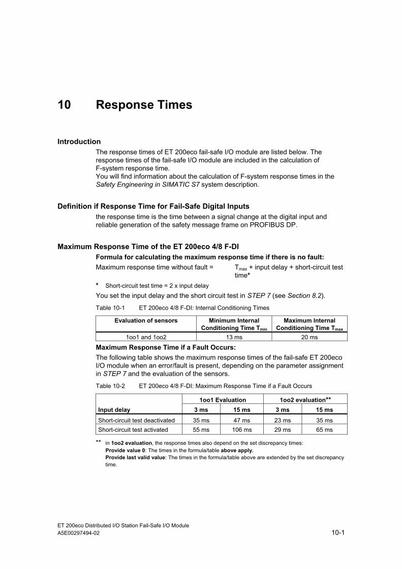
ET 200eco Distributed I/O Station Fail-Safe I/O Module A5E00297494-02 10-1
10 Response Times
Introduction The response times of ET 200eco fail-safe I/O module are listed below. The response times of the fail-safe I/O module are included in the calculation of F-system response time. You will find information about the calculation of F-system response times in the Safety Engineering in SIMATIC S7 system description.
Definition if Response Time for Fail-Safe Digital Inputs the response time is the time between a signal change at the digital input and reliable generation of the safety message frame on PROFIBUS DP.
Maximum Response Time of the ET 200eco 4/8 F-DI Formula for calculating the maximum response time if there is no fault: Maximum response time without fault = Tmax + input delay + short-circuit test
time* * Short-circuit test time = 2 x input delay You set the input delay and the short circuit test in STEP 7 (see Section 8.2).
Table 10-1 ET 200eco 4/8 F-DI: Internal Conditioning Times
Evaluation of sensors Minimum Internal Conditioning Time Tmin
Maximum Internal Conditioning Time Tmax
1oo1 and 1oo2 13 ms 20 ms
Maximum Response Time if a Fault Occurs: The following table shows the maximum response times of the fail-safe ET 200eco I/O module when an error/fault is present, depending on the parameter assignment in STEP 7 and the evaluation of the sensors.
Table 10-2 ET 200eco 4/8 F-DI: Maximum Response Time if a Fault Occurs
1oo1 Evaluation 1oo2 evaluation** Input delay 3 ms 15 ms 3 ms 15 ms
Short-circuit test deactivated 35 ms 47 ms 23 ms 35 ms Short-circuit test activated 55 ms 106 ms 29 ms 65 ms
** in 1oo2 evaluation, the response times also depend on the set discrepancy times: Provide value 0: The times in the formula/table above apply. Provide last valid value: The times in the formula/table above are extended by the set discrepancy time.

Response Times
ET 200eco Distributed I/O Station Fail-Safe I/O Module 10-2 A5E00297494-02
Note
The MS Excel files for calculating maximum response times (s7fcotib.xls or s7ftimeb.xls) provided with the S7 Distributed Safety and S7 F/FH Systems optional packages support calculation of the “maximum response time when a fault is present” by increasing the response time by the amount of the parameterized discrepancy time.

ET 200eco Distributed I/O Station Fail-Safe I/O Module A5E00297494-02 11-1
11 Glossary
1oo1 Evaluation 1oo1 evaluation is a type of sensor evaluation in which one -> sensor is
connected to the fail-safe I/O module by means of a single channel.
1oo2 Evaluation -> Sensor evaluation method - In 1oo2 evaluation, two input channels are occupied, either by one 2-channel sensor or two single-channel sensors. The input signals are compared internally for equality (equivalence) or non-equality (nonequivalence).
A
Acknowledgment Time
During the acknowledgement time, the -> F-I/O acknowledge the sign of life specified by the -> F-CPU. The acknowledgement time enters into the calculation of the -> monitoring time and -> response time for the F-system as a whole.
Actuator Actuators can be power relays or contactors for switching on consumers, or they can be consumers themselves (for example, directly controlled solenoid valves).
Availability Availability is the probability that a system is functional at a specific point in time. Availability can be increased by redundancy, e.g., by using redundant signal modules and/or by using multiple -> sensors at the same measuring point.
C
Category Category in accordance with EN 954-01:
With -> fail-safe I/O modules, up to category 4 can be achieved in safety mode.
Channel Fault A channel fault is a channel-related fault, such as a wire break or a short circuit.
Glossary
ET 200eco Distributed I/O Station Fail-Safe I/O Module 11-2 A5E00297494-02
Channel Group The channels of a module are grouped together in a channel group. Certain parameters in STEP 7 can only be assigned to channel groups, rather than to individual channels.
Channel Number The inputs of an I/O module are identified uniquely by means of the channel number and the channel-specific diagnostic messages are assigned.
Channel-specific passivation
In this passivation method, when a -> channel fault occurs, only the channel involved is passivated (method available in S7 F/FH systems only). In the event of a module fault, all channels of the -> fail-safe I/O module are passivated.
Configuration Systematic arrangement of individual I/O modules (configuration)
CRC Cyclic Redundancy Check
CRC Signature A CRC signature in the safety message frame is used to safeguard the validity of the process values in the safety message frame, the correctness of the assigned address references, and the safety-related parameters.
D
Discrepancy Analysis
Discrepancy analysis for equivalence or nonequivalence is used for fail-safe inputs to determine faults based on the time characteristic of two signals with the same functionality. Discrepancy analysis is initiated when different levels are detected for two associated input signals (for nonequivalence testing, when the same levels are detected). After a programmable time interval (so-called -> discrepancy time) has elapsed, a check is made to determine whether the difference has disappeared (for nonequivalence testing, whether the agreement has disappeared). If not, this means that a discrepancy error exists.
There are two types of discrepancy analyses for fail-safe input modules: • In the case of -> 1oo2 evaluation:
The discrepancy analysis is carried out between the two input signals of the 1oo2 evaluation in the fail-safe input module.
• In the case of redundant I/O (S7 FH systems only):
The discrepancy analysis is performed between the two input signals of the redundant input modules by the fail-safe driver blocks of the S7 F Systems optional software.

Glossary
ET 200eco Distributed I/O Station Fail-Safe I/O Module A5E00297494-02 11-3
Discrepancy Time Discrepancy time is a period of time configured for the -> discrepancy analysis. If the discrepancy time is set too high, the times for fault detection and -> fault response are extended unnecessarily. If the discrepancy time is set too low, availability is decreased unnecessarily because a discrepancy error is detected when, in reality, no fault exists.
F
Fail-safe I/O module The ET 200eco I/O module that can be used for safety-related operation (-> safety mode) in S7 Distributed Safety or S7 F/FH fail-safe systems. This I/O module has integrated -> safety functions.
Fail-Safe Systems Fail-safe systems (F-systems) are systems that remain in a safe state or immediately switch to another safe state as soon as particular failures occur.
Fault reaction time The maximum fault reaction time for an F-system is the time between the occurrence of any fault and a safe response at all affected fail-safe outputs. For -> F-System in total: The maximum fault reaction time is the time between occurrence of any fault in any -> F-I/O and a safe response at the relevant fail-safe output.
For inputs: The maximum fault reaction time is the time between the occurrence of a fault and a safe response at the backplane bus/on PROFIBUS DP.
For digital outputs: The maximum fault reaction time is the time between the occurrence of a fault and a safe response at the digital output.
Fault Tolerance Time
The fault tolerance time of a process is a time interval during which the process can be left on its own without risk to life and limb of the operating personnel or damage to the environment.
Within the fault tolerance time, any type of F-system process control is tolerated. That is, during this time, the -> F-system can control its process incorrectly or it can even exercise no control at all. The fault tolerance time depends on the process type and must be determined on a case-by-case basis.
F-CPU An F-CPU is a central processing unit with fail-safe capability that is permitted for use in S7 Distributed Safety/S7 F/FH systems. For S7 F/FH systems, the F-copy license allows the central processing unit to be used as an F-CPU. That is, it can execute a -> safety program. For S7 Distributed Safety, an F-copy license is not required. A standard user program can also be run on the F-CPU.

Glossary
ET 200eco Distributed I/O Station Fail-Safe I/O Module 11-4 A5E00297494-02
F-I/O F-I/O is a group designation for fail-safe inputs and outputs available in SIMATIC S7 for integration in S7 Distributed Safety and S7 F/FH systems. The following F-I/O modules are available: • Fail-safe ET 200eco I/O module
• S7-300 fail-safe signal modules (F-SMs)
• ET 200S fail-safe module
• Fail-safe DP standard slaves (for S7 Distributed Safety only)
F-monitoring time -> PROFIsafe monitoring time
F-Systems -> Fail-safe systems
I
I/O Module Fault I/O module faults can be external faults (for example, missing load voltage) or internal faults (for example, processor failure). An internal fault always requires I/O module replacement.
M
Monitoring Time -> PROFIsafe monitoring time
N
Nonequivalent Sensor
A nonequivalent -> sensor is a reversing switch that is connected to two inputs of an -> F-I/O (via 2 channels) in -> fail-safe systems (for -> 1oo2 evaluation of sensor signals).
P
Parameter Assignment
Parameter assignment via PROFIBUS DP: Transfer of slave parameters from the DP master to the DP slave
Parameter assignment of modules: Setting the module behavior using the STEP 7 configuration software

Glossary
ET 200eco Distributed I/O Station Fail-Safe I/O Module A5E00297494-02 11-5
Passivation If an -> F-I/O module detects a fault, it switches either the affected channel or all channels to a -> safe state; that is, the channels of the F-I/O module are passivated. The F-I/O signals the detected faults to the CPU.
For an F-I/O with inputs, if passivation occurs, the F-system provides fail-safe values for the safety program instead of the process values pending at the fail-safe inputs.
For an I/O module with outputs, if passivation occurs, the F-system transfers fail-safe values (0) to the fail-safe outputs instead of the output values provided by the safety program.
PG Programming devices (PGs) are compactly designed personal computers made especially for use in an industrial setting. A programming device (PG) is fully equipped for programming SIMATIC automation systems.
Process Image The process image is a component of the system memory of the CPU. At the start of the cyclical program, the signal states of the input modules/submodules are transferred to the process image of the inputs. At the end of the cyclic program, the process image of the outputs is transferred to the output modules/submodules as the signal state.
PROFIBUS PROcess FIeld BUS, German process and fieldbus standard specified in IEC 61784-1:2002 Ed1 CP 3/1. This standard specifies functional, electrical, and mechanical properties for a bit-serial field bus system.
PROFIBUS is available with the following protocols: DP (= distributed I/O), FMS (= Fieldbus message specification), PA (= Process automation), or TF (= Technological functions).
PROFIsafe Safety-related PROFIBUS DP/PA bus profile for communication between the -> safety program and the -> fail-safe I/O in a -> fail-safe system.
PROFIsafe Address Every -> F-I/O module has a PROFIsafe address You must configure the PROFIsafe address in STEP 7 HW Config and set it on the F-I/O using a switch.
PROFIsafe Monitoring Time
Monitoring time for safety-related communication between the F-CPU and F-I/O
Proof-Test Interval A component must be set in the fail-safe state following the proof-test interval. That is, it is replaced by an unused component or it is proven to be completely without faults.
Glossary
ET 200eco Distributed I/O Station Fail-Safe I/O Module 11-6 A5E00297494-02
R
Redundancy, Availability-Enhancing
Availability-enhancing redundancy means multiple availability of components to ensure that components continue to function even in the event of hardware faults.
Redundancy, Safety-Enhancing
Multiple availability of components with the aim of exposing hardware faults based on comparison (for example, -> 1oo2 evaluation in fail-safe signal modules.
Reintegration Once a fault has been eliminated, the -> F-I/O must be reintegrated (depassivated). The reintegration (switchover from fail-safe values to process values) occurs either automatically or only after user acknowledgement in the safety program.
For an F-I/O module with inputs, the process values pending at the fail-safe inputs are provided again for the -> safety program after reintegration. For an F-I/O module with outputs, the -> F-system again transfers the output values provided in the safety program to the fail-safe outputs.
Response Time Response time starts with the detection of an input signal and ends with the modification of a gated output signal.
The actual response time is between the shortest and the longest response time. The longest response time must always be anticipated.
For fail-safe inputs: the response time represents the time between a signal change at the input and safe delivery of the safety message frame on the backplane bus.
For fail-safe digital outputs: the response time represents the time between an arriving safety message frame from the backplane bus and the signal change at the digital output.
S
Safe State The basis of the safety concept for fail-safe systems is that there is a safe state for all process variables. For digital fail-safe I/O modules, the safe state is, for example, the value "0".
Safety Function Safety function is a mechanism built into the -> F-CPU and -> F-I/O that allows them to be used in -> S7 Distributed Safety or S7 F/FH systems.
IEC 61508: Function implemented by a safety system to ensure that the system is kept in a safe state or brought to a safe state in the event of a particular fault.

Glossary
ET 200eco Distributed I/O Station Fail-Safe I/O Module A5E00297494-02 11-7
Safety Integrity Level
The safety integrity level (SIL) is a safety class in accordance with IEC 61508 and prEN 50129. The higher the safety integrity level, the stricter the measures must be to prevent and eliminate systematic faults and to remedy hardware failures.
With fail-safe ET 200eco I/O modules, safety-integrity levels up to SIL 3 can be achieved in safety mode.
Safety Message Frame
In safety mode, data is transferred between the -> F-CPU and -> the fail-safe I/O module in a safety message frame.
Safety Mode Safety mode is the operating mode of the -> F-I/O that allows -> safety-related communication by means of -> safety message frames. -> ET 200eco fail-safe I/O modules can only be used in safety mode.
Safety Program The safety program is a safety-related user program.
Safety Requirement Class (AK)
Safety requirement class (AK) in accordance with DIN V 19250 (DIN V VDE 0801):
Safety requirement classes are a means of categorizing safety requirements for preventing and remedying faults. With -> fail-safe I/O modules, safety requirement classes up to AK6 can be used in -> safety mode.
Safety-Related Communication
Safety-related communication is used to exchange fail-safe data.
Sensor Sensors permit exact acquisition of digital and analog signals and exact measurement of routes, positions, velocities, rotational speeds, weights, etc.
Sensor Evaluation There are two types of sensor evaluation:
• -> 1oo1 evaluation – Sensor signal is read out once
• -> 1oo2 evaluation: To increase availability, the sensor signal is read twice by the same -> fail-safe I/O and compared internally.
Standard Mode Operating mode of F-I/O, in which standard communication is possible but not -> safety-related communication by means of -> safety message frames.
ET 200eco fail-safe I/O modules can only be used in -> safety mode.
Static Parameter Static parameters can only be set when the CPU is in STOP mode and cannot be changed by means of SFC (system function) while the user program is running.

Glossary
ET 200eco Distributed I/O Station Fail-Safe I/O Module 11-8 A5E00297494-02
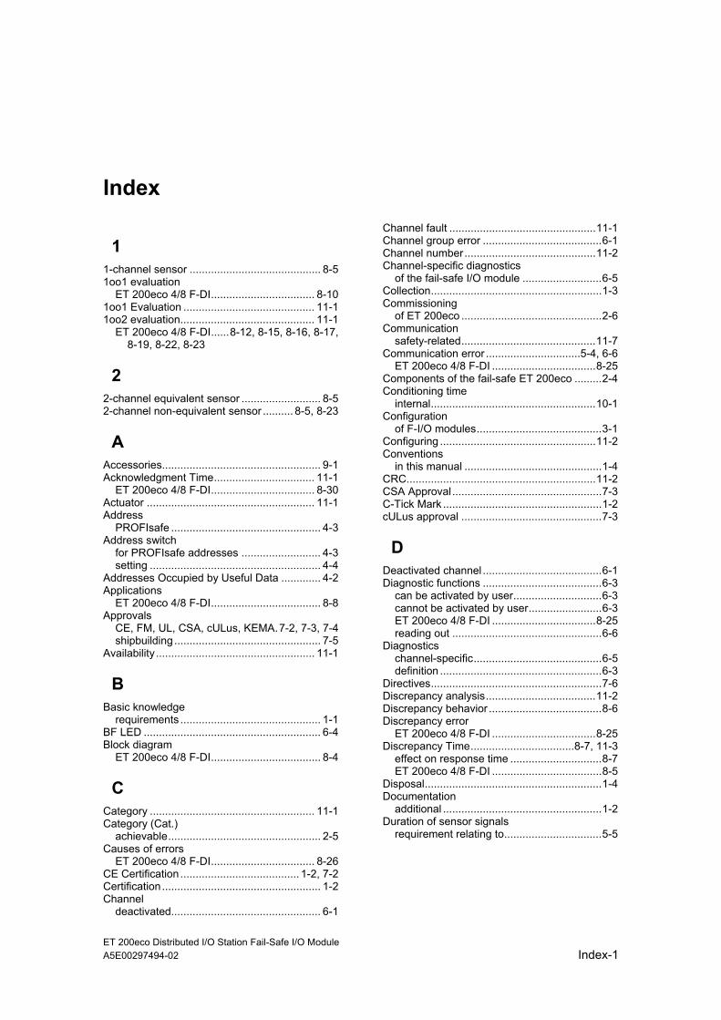
ET 200eco Distributed I/O Station Fail-Safe I/O Module A5E00297494-02 Index-1
Index
1 1-channel sensor ........................................... 8-5 1oo1 evaluation
ET 200eco 4/8 F-DI.................................. 8-10 1oo1 Evaluation ........................................... 11-1 1oo2 evaluation............................................ 11-1
ET 200eco 4/8 F-DI......8-12, 8-15, 8-16, 8-17, 8-19, 8-22, 8-23
2 2-channel equivalent sensor .......................... 8-5 2-channel non-equivalent sensor .......... 8-5, 8-23
A Accessories.................................................... 9-1 Acknowledgment Time................................. 11-1
ET 200eco 4/8 F-DI.................................. 8-30 Actuator ....................................................... 11-1 Address
PROFIsafe ................................................. 4-3 Address switch
for PROFIsafe addresses .......................... 4-3 setting ........................................................ 4-4
Addresses Occupied by Useful Data ............. 4-2 Applications
ET 200eco 4/8 F-DI.................................... 8-8 Approvals
CE, FM, UL, CSA, cULus, KEMA.7-2, 7-3, 7-4 shipbuilding ................................................ 7-5
Availability .................................................... 11-1
B Basic knowledge
requirements .............................................. 1-1 BF LED .......................................................... 6-4 Block diagram
ET 200eco 4/8 F-DI.................................... 8-4
C Category ...................................................... 11-1 Category (Cat.)
achievable.................................................. 2-5 Causes of errors
ET 200eco 4/8 F-DI.................................. 8-26 CE Certification ....................................... 1-2, 7-2 Certification.................................................... 1-2 Channel
deactivated................................................. 6-1
Channel fault ................................................11-1 Channel group error .......................................6-1 Channel number...........................................11-2 Channel-specific diagnostics
of the fail-safe I/O module ..........................6-5 Collection........................................................1-3 Commissioning
of ET 200eco ..............................................2-6 Communication
safety-related............................................11-7 Communication error ...............................5-4, 6-6
ET 200eco 4/8 F-DI ..................................8-25 Components of the fail-safe ET 200eco .........2-4 Conditioning time
internal......................................................10-1 Configuration
of F-I/O modules.........................................3-1 Configuring ...................................................11-2 Conventions
in this manual .............................................1-4 CRC..............................................................11-2 CSA Approval.................................................7-3 C-Tick Mark ....................................................1-2 cULus approval ..............................................7-3
D Deactivated channel .......................................6-1 Diagnostic functions .......................................6-3
can be activated by user.............................6-3 cannot be activated by user........................6-3 ET 200eco 4/8 F-DI ..................................8-25 reading out .................................................6-6
Diagnostics channel-specific..........................................6-5 definition .....................................................6-3
Directives........................................................7-6 Discrepancy analysis....................................11-2 Discrepancy behavior .....................................8-6 Discrepancy error
ET 200eco 4/8 F-DI ..................................8-25 Discrepancy Time..................................8-7, 11-3
effect on response time ..............................8-7 ET 200eco 4/8 F-DI ....................................8-5
Disposal..........................................................1-4 Documentation
additional ....................................................1-2 Duration of sensor signals
requirement relating to................................5-5
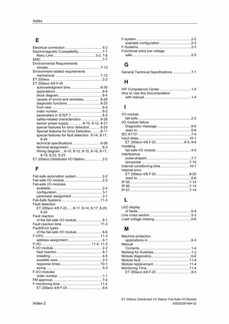
Index
ET 200eco Distributed I/O Station Fail-Safe I/O Module Index-2 A5E00297494-02
E Electrical connection ...................................... 5-2 Electromagnetic Compatibility........................ 7-7
Retry Limit........................................... 3-2, 7-8 EMC............................................................... 7-7 Environmental Requirements
climatic ..................................................... 7-13 Environment-related requirements
mechanical............................................... 7-12 ET 200eco ..................................................... 2-2 ET 200eco 4/8 F-DI
acknowledgment time .............................. 8-30 applications ................................................ 8-8 block diagram............................................. 8-4 causes of errors and remedies................. 8-26 diagnostic functions ................................. 8-25 front view ................................................... 8-2 order number ............................................. 8-2 parameters in STEP 7................................ 8-5 safety-related characteristics ................... 8-28 sensor power supply ..............8-10, 8-12, 8-21 special features for error detection........... 8-20 Special features for Error Detection ......... 8-11 special features for fault detection . 8-14, 8-17,
8-24 technical specifications ............................ 8-28 terminal assignment................................... 8-3 Wiring diagram....8-10, 8-12, 8-15, 8-16, 8-17,
8-19, 8-22, 8-23 ET 200eco Distributed I/O Station.................. 2-2
F Fail-safe automation system .......................... 2-2 Fail-safe I/O module....................................... 2-2 Fail-safe I/O modules
available..................................................... 2-4 configuration .............................................. 3-1 parameter assignment ............................... 3-1
Fail-Safe Systems........................................ 11-3 Fault detection
ET 200eco 4/8 F-DI......8-11, 8-14, 8-17, 8-20, 8-24
Fault reaction of the fail-safe I/O module.......................... 6-1
Fault reaction time ....................................... 11-3 Fault/Error types
of the fail-safe I/O module.......................... 6-6 F-CPU.......................................................... 11-3
address assignment................................... 4-1 F-I/O.................................................... 11-4, 11-5 F-I/O module .................................................. 2-2
fault reaction .............................................. 6-1 installing..................................................... 4-5 possible uses ............................................. 2-2 response times......................................... 10-1 wiring ......................................................... 5-3
F-I/O modules order number ............................................. 1-1
FM approval ................................................... 7-4 F-monitoring time ......................................... 11-4
ET 200eco 4/8 F-DI.................................... 8-5
F-system.........................................................2-2 example configuration ................................2-3
F-Systems ......................................................2-3 Functional extra low voltage
safe.............................................................5-2
G General Technical Specifications ...................7-1
H H/F Competence Center.................................1-5 How to Use this Documentation
with manual ................................................1-4
I I/O module
fail-safe.......................................................2-2 I/O module failure
Diagnostic message ...................................6-6 react to .......................................................6-6
IEC 61131 ......................................................7-4 Input delay....................................................10-1
ET 200eco 4/8 F-DI .............................8-5, 8-6 Installing
fail-safe I/O module ....................................4-5 Interference
pulse-shaped..............................................7-7 sinusoidal .................................................7-10
Internal conditioning time..............................10-1 Internal error
ET 200eco 4/8 F-DI ..................................8-25 react to .......................................................6-6
IP 65.............................................................7-14 IP 66.............................................................7-14 IP 67.............................................................7-14
L LED display
of faults.......................................................6-4 Line cross section...........................................5-2 Load voltage missing......................................6-6
M Machine protection
applications in.............................................6-3 Manual
Contents .....................................................1-4 Marking for Australia.......................................1-2 Module diagnostics.........................................6-6 Module fault..................................................11-4 Module replacement .....................................11-4 Monitoring Time............................................11-4
ET 200eco 4/8 F-DI ....................................8-5
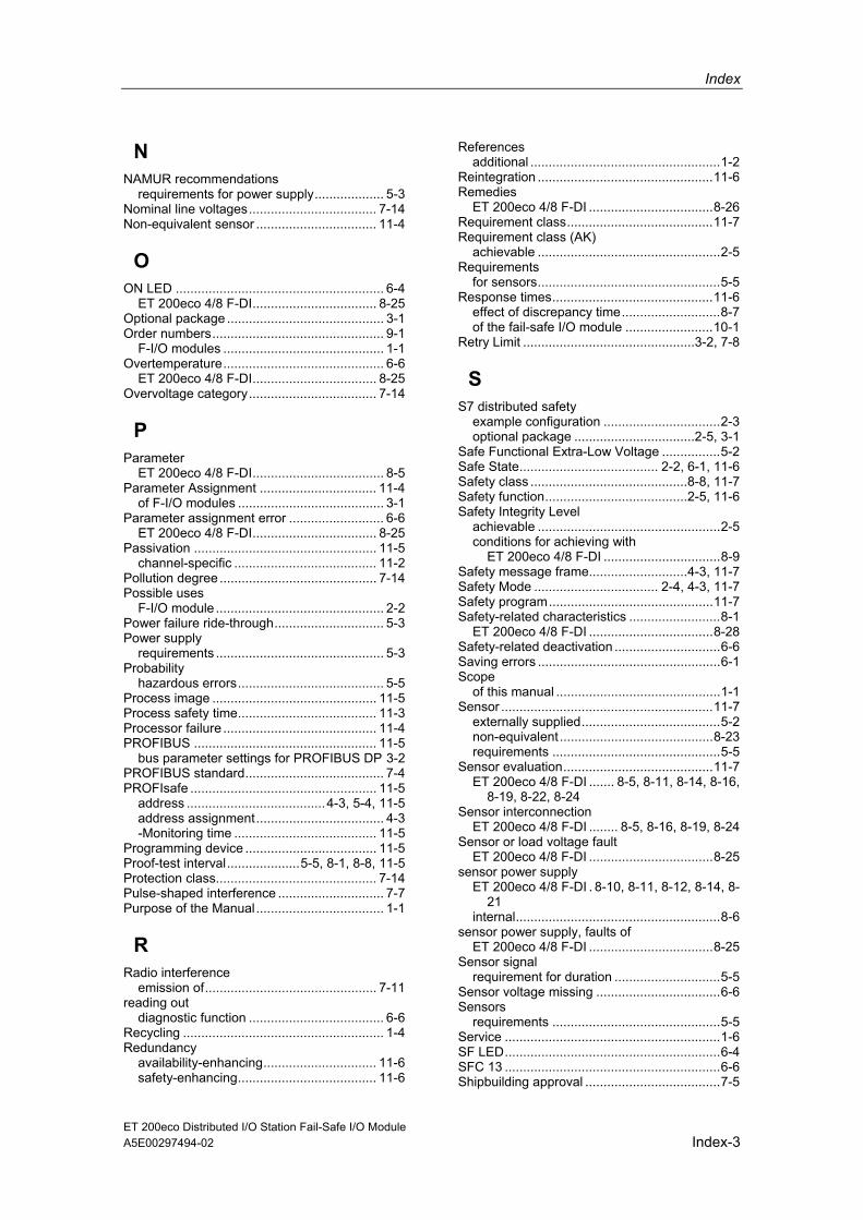
Index
ET 200eco Distributed I/O Station Fail-Safe I/O Module A5E00297494-02 Index-3
N NAMUR recommendations
requirements for power supply................... 5-3 Nominal line voltages................................... 7-14 Non-equivalent sensor ................................. 11-4
O ON LED ......................................................... 6-4
ET 200eco 4/8 F-DI.................................. 8-25 Optional package ........................................... 3-1 Order numbers............................................... 9-1
F-I/O modules ............................................ 1-1 Overtemperature............................................ 6-6
ET 200eco 4/8 F-DI.................................. 8-25 Overvoltage category................................... 7-14
P Parameter
ET 200eco 4/8 F-DI.................................... 8-5 Parameter Assignment ................................ 11-4
of F-I/O modules ........................................ 3-1 Parameter assignment error .......................... 6-6
ET 200eco 4/8 F-DI.................................. 8-25 Passivation .................................................. 11-5
channel-specific ....................................... 11-2 Pollution degree ........................................... 7-14 Possible uses
F-I/O module .............................................. 2-2 Power failure ride-through.............................. 5-3 Power supply
requirements .............................................. 5-3 Probability
hazardous errors........................................ 5-5 Process image ............................................. 11-5 Process safety time...................................... 11-3 Processor failure .......................................... 11-4 PROFIBUS .................................................. 11-5
bus parameter settings for PROFIBUS DP 3-2 PROFIBUS standard...................................... 7-4 PROFIsafe ................................................... 11-5
address ......................................4-3, 5-4, 11-5 address assignment................................... 4-3 -Monitoring time ....................................... 11-5
Programming device .................................... 11-5 Proof-test interval....................5-5, 8-1, 8-8, 11-5 Protection class............................................ 7-14 Pulse-shaped interference ............................. 7-7 Purpose of the Manual................................... 1-1
R Radio interference
emission of............................................... 7-11 reading out
diagnostic function ..................................... 6-6 Recycling ....................................................... 1-4 Redundancy
availability-enhancing............................... 11-6 safety-enhancing...................................... 11-6
References additional ....................................................1-2
Reintegration ................................................11-6 Remedies
ET 200eco 4/8 F-DI ..................................8-26 Requirement class........................................11-7 Requirement class (AK)
achievable ..................................................2-5 Requirements
for sensors..................................................5-5 Response times............................................11-6
effect of discrepancy time...........................8-7 of the fail-safe I/O module ........................10-1
Retry Limit ...............................................3-2, 7-8
S S7 distributed safety
example configuration ................................2-3 optional package .................................2-5, 3-1
Safe Functional Extra-Low Voltage ................5-2 Safe State...................................... 2-2, 6-1, 11-6 Safety class ...........................................8-8, 11-7 Safety function.......................................2-5, 11-6 Safety Integrity Level
achievable ..................................................2-5 conditions for achieving with
ET 200eco 4/8 F-DI ................................8-9 Safety message frame...........................4-3, 11-7 Safety Mode .................................. 2-4, 4-3, 11-7 Safety program.............................................11-7 Safety-related characteristics .........................8-1
ET 200eco 4/8 F-DI ..................................8-28 Safety-related deactivation .............................6-6 Saving errors ..................................................6-1 Scope
of this manual .............................................1-1 Sensor ..........................................................11-7
externally supplied......................................5-2 non-equivalent ..........................................8-23 requirements ..............................................5-5
Sensor evaluation.........................................11-7 ET 200eco 4/8 F-DI ....... 8-5, 8-11, 8-14, 8-16,
8-19, 8-22, 8-24 Sensor interconnection
ET 200eco 4/8 F-DI ........ 8-5, 8-16, 8-19, 8-24 Sensor or load voltage fault
ET 200eco 4/8 F-DI ..................................8-25 sensor power supply
ET 200eco 4/8 F-DI . 8-10, 8-11, 8-12, 8-14, 8-21
internal........................................................8-6 sensor power supply, faults of
ET 200eco 4/8 F-DI ..................................8-25 Sensor signal
requirement for duration .............................5-5 Sensor voltage missing ..................................6-6 Sensors
requirements ..............................................5-5 Service ...........................................................1-6 SF LED...........................................................6-4 SFC 13 ...........................................................6-6 Shipbuilding approval .....................................7-5

Index
ET 200eco Distributed I/O Station Fail-Safe I/O Module Index-4 A5E00297494-02
Short-circuit.................................................... 6-6 ET 200eco 4/8 F-DI................8-11, 8-14, 8-25
Short-circuit test .................................... 6-3, 10-1 ET 200eco 4/8 F-DI.8-5, 8-6, 8-11, 8-14, 8-16,
8-19, 8-22, 8-24, 8-25 Sinusoidal interference ................................ 7-10 Slave Diagnostics .......................................... 6-4
Reading out................................................ 6-6 Standard Mode ............................................ 11-7 Standard Operation........................................ 2-4 Standards ............................................... 1-2, 7-6 Startup of the fail-safe system........................ 6-1 Static parameters......................................... 11-7 Storage conditions ....................................... 7-11 Support .......................................................... 1-6
additional ................................................... 1-4
T Technical specifications
ET 200eco 4/8 F-DI.................................. 8-28 Technical Specifications
general ....................................................... 7-1 Terminal assignment
ET 200eco 4/8 F-DI.................................... 8-3 Training center ............................................... 1-5 Transport and storage conditions................. 7-11
TÜV certificate................................................7-6 Type of Protection
IP 65.........................................................7-14 IP 66.........................................................7-14 IP 67.........................................................7-14
U UL approval ....................................................7-3
V Vibration .......................................................7-12 Voltages
nominal line ..............................................7-14
W Wiring
fail-safe I/O modules...................................5-3 wiring diagram
ET 200eco 4/8 F-DI ..................................8-16 Wiring diagram
ET 200eco 4/8 F-DI ..... 8-10, 8-12, 8-15, 8-17, 8-19, 8-22, 8-23

SIMATIC S7 Distributed Safety: feedback for Version 03/2004A5E00297771-01
Siemens AG
A&D AS SM IDPostfach 1963D-92209 Amberg
Telefax: +49(9621)80-3103mailto:[email protected]
Your Feedback as regards the S7 Distributed Safety (Version 03/2004)
Dear SIMATIC user,
Our goal is to provide you information with a high degree of quality and usability, and to continuouslyimprove the SIMATIC documentation for you. To achieve this goal, we require your feedback andsuggestions. Please take a few minutes to fill out this questionnaire and return it to me by Fax, e-mail orby post.
We are giving out three presents every month in a raffle among the senders. Which present would youlike to have?
SIMATIC Manual Collection Automation Value Card Laser pointer
Dr. Thomas Rubach,Head of Information & Documentation
General Questions
1. Are you familiar with the SIMATIC ManualCollection?
yes no
2. Have you ever downloaded manuals from theinternet?
yes no
3. Do you use Getting Starteds?
yes no
if yes, which:
4. How much experience do you have with theS7 Distributed Safety?
Expert
Experienced user
Advanced user
Beginner
Your Address:
Name:
Company:
Position:
Street:
Postal code / Place:
Email:
Phone:
Fax:

SIMATIC S7 Distributed Safety: feedback for Version 03/2004A5E00297771-01
Please specify the documents, for which you want to answer the questions below:
A: Manual S7 Distributed Safety, D: Manual ET 200eco, Distributed I/O Configuring and Programming Fail-Safe I/O Module
B: Manual S7-300, Fail-Safe E: System DescriptionSignal Modules Safety Engineering in SIMATIC S7
C: Manual ET 200S, Distributed I/O SystemFail-Safe Modules
1. In which project phase do you use thisdocument frequently?
Information Assembly
Planning Commissioning
Configuration Maintenance & Service
Programming others:
2. Finding the required information in thedocument:
How quickly can you find the desired information inthe document?
immediately not at all
after a brief after a long search search
Which search method do you prefer?
Table of contents Index
Full-text search others:
Which supplements/improvements would you like in order to help you find the required information quickly?
3. Your judgement of the document as regardscontent.
How satisfied are you with this document
Totally satisfied not very satisfied
Very satisfied not satisfied
Satisfied
Were able to find the required information?
yes no
which was not:
4. What is the scope of the information?
Just right
Not enough - which topic:
Too detailed – which topic:
5. Is the information easy to understand (texts,figures, tables)?
yes no
if no, which was not:
6. Are examples important to you?
no, of less importance
yes, important –were the examplesenough?
yes no
if no, on which topic:
7. What are your suggestions as regards thecontents of the document?
Thank you for your cooperation

s
Copyright © Siemens AG 2007
Siemens Aktiengesellschaft A5E00470176-02
SIMATIC
Product Information 04/2007
Manual ET 200eco Distributed I/O Station, Failsafe I/O Module
Diese Produktinformation enthält wichtige Informationen zum Handbuch Dezentrales Peripheriegerät ET 200eco, Fehlersicheres Peripheriemodul, Ausgabe 06/2004, A5E00297493-02. Die Produktinformation ist Bestandteil des gelieferten Produkts und die darin enthaltenen Aussagen sind in Zweifelsfällen in der Verbindlichkeit anderen Aussagen übergeordnet.
This Product Information contains important information about manual ET 200eco Distributed I/O Station, Fail-Safe I/O Module, Edition 06/2004, A5E00297494-02. The Product Information is part of the product supplied and the information in it should be considered more up-to-date if uncertainties arise.
Cette information produit contient des informations importantes manuel ET 200eco Périphérie décentralisée, Module de périphérie de Sécurité, Edition 06/2004, A5E00297495-02. L'information produit fait partie du produit livré et, en cas de doute, c’est à elle que vous devez vous reporter.
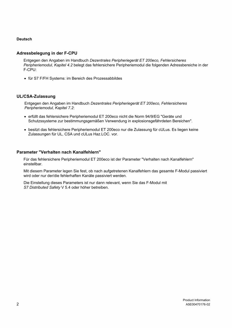
Product Information 2 A5E00470176-02
Deutsch
Adressbelegung in der F-CPU Entgegen den Angaben im Handbuch Dezentrales Peripheriegerät ET 200eco, Fehlersicheres Peripheriemodul, Kapitel 4.2 belegt das fehlersichere Peripheriemodul die folgenden Adressbereiche in der F-CPU:
• für S7 F/FH Systems: im Bereich des Prozessabbildes
UL/CSA-Zulassung Entgegen den Angaben im Handbuch Dezentrales Peripheriegerät ET 200eco, Fehlersicheres Peripheriemodul, Kapitel 7.2:
• erfüllt das fehlersichere Peripheriemodul ET 200eco nicht die Norm 94/9/EG "Geräte und Schutzssysteme zur bestimmungsgemäßen Verwendung in explosionsgefährdeten Bereichen".
• besitzt das fehlersichere Peripheriemodul ET 200eco nur die Zulassung für cULus. Es liegen keine Zulassungen für UL, CSA und cULus Haz.LOC. vor.
Parameter "Verhalten nach Kanalfehlern" Für das fehlersichere Peripheriemodul ET 200eco ist der Parameter "Verhalten nach Kanalfehlern" einstellbar.
Mit diesem Parameter legen Sie fest, ob nach aufgetretenen Kanalfehlern das gesamte F-Modul passiviert wird oder nur der/die fehlerhaften Kanäle passiviert werden.
Die Einstellung dieses Parameters ist nur dann relevant, wenn Sie das F-Modul mit S7 Distributed Safety V 5.4 oder höher betreiben.

Product Information A5E00470176-02 3
Englisch
Address Assignment in the F-CPU Contrary to the information in the manual ET 200eco Distributed I/O Station, Fail-Safe I/O Module, section 4.2, the fail safe distributed I/O station assigns the following address range in the F-CPU:
• For S7 F/FH systems: in the process image range
UL/CSA Approval Contrary to the information in the manual ET 200eco Distributed I/O Station, Fail-Safe I/O Module, section 7.2:
• The Fail-Safe I/O Module ET 200eco does not fulfill the norm: 94/9/EC "Equipment and Protective Systems Intended for Use in Potentially Explosive Atmospheres" (Explosion Protection Guideline).
• The Fail-Safe I/O Module ET 200eco only has cULus approval. Approvals for UL, CSA and cULus Haz.LOC. are not available.
Parameter "Behavior after Channel Faults"
The Fail-Safe I/O Module ET 200eco setting "Behavior after Channel Faults" is configurable.
This parameter is used to specify whether the entire F-module is passivated or just the faulty channel(s) in the event of channel faults.
The setting of this parameter is only relevant if you operate the F-module with S7 Distributed Safety V5.4 or higher.
Section 8.2.4 Application 3: Safety Mode AK6/SIL3/Category 4 There is a mistake on pages 8-22 and 8-24 in the manual ET 200eco Distributed I/O Station, Fail-Safe I/O Module, section 8.2.4 Application 3: Safety Mode AK6/SIL3/Category 4.
The correct translation for the last sentence in the paragraph Assignable Parameters for Application 3.1 and Assignable Parameters for Application 3.2 should be: Activate the parameter "short-circuit test.“

Product Information 4 A5E00470176-02
Französisch
Affectation d'adresse dans la CPU F Contrairement aux informations du manuel Station de périphérie décentralisée ET 200eco, Module de périphérie de sécurité, chapitre 4.2, le module de périphérie de sécurité occupe les zones d’adresses suivantes dans la CPU F
• Pour S7 F/FH Systems : dans la mémoire image
Homologation UL/CSA Contrairement aux informations du manuel Station de périphérie décentralisée ET 200eco, Module de périphérie de sécurité, chapitre 7.2 :
• le module de périphérie de sécurité ET 200eco n’est pas conforme à la norme 94/9/CE "Appareils et systèmes de protection destinés à être utilisés en atmosphères explosibles" (directive de protection contre les explosions)
• le module de périphérie de sécurité ET 200eco ne possède que l’homologation pour cULus. Il ne possède pas d’homologation pour UL, CSA und cULus Haz.LOC.
Paramètre "Réaction aux erreurs de voie" Le paramètre “Réaction aux erreurs de voie“ peut être sélectionné pour le module de périphérie de sécurité ET 200eco.
Ce paramètre détermine si l'ensemble du module F doit être passivé à la suite d'erreurs de voie ou uniquement les voies défectueuses.
Ce paramètre n'est significatif que si le module F est exploité avec S7 Distributed Safety V 5.4 ou une version supérieure.