
ESTIMATION OF ACL FORCES UTILIZING A NOVEL...
77
ESTIMATION OF ACL FORCES UTILIZING A NOVEL NON-INVASIVE METHODOLOGY THAT REPRODUCES KNEE KINEMATICS BETWEEN SETS OF KNEES by Shon Patrick Darcy BS, Walla Walla College, 2000 Submitted to the Graduate Faculty of School of Engineering in partial fulfillment of the requirements for the degree of Masters of Science in Bioengineering University of Pittsburgh 2003
Transcript of ESTIMATION OF ACL FORCES UTILIZING A NOVEL...

ESTIMATION OF ACL FORCES UTILIZING A NOVEL NON-INVASIVE METHODOLOGY THAT REPRODUCES KNEE KINEMATICS BETWEEN SETS OF KNEES
by
Shon Patrick Darcy
BS, Walla Walla College, 2000
Submitted to the Graduate Faculty of
School of Engineering in partial fulfillment
of the requirements for the degree of
Masters of Science in Bioengineering
University of Pittsburgh
2003
ii
UNIVERSITY OF PITTSBURGH
SCHOOL OF ENGINEERING
This thesis was presented
by
Shon Patrick Darcy
It was defended on
July 29, 2003
and approved by
Dr. Freddie H. Fu, Professor, Department of Orthopaedic Surgery
Rakié Cham, Assistant Professor, Department of Bioengineering
Savio L-Y. Woo, Professor, Department of Orthopaedic Surgery, Bioengineering, Mechanical Engineering, Rehabilitation Science & Technology
Thesis Director: Richard E. Debski, Assistant Professor, Departments of Orthopaedic Surgery & Bioengineering
iii
ABSTRACT
ESTIMATION OF ACL FORCES UTILIZING A NOVEL NON-INVASIVE METHODOLOGY THAT REPRODUCES KNEE KINEMATICS BETWEEN SETS OF
KNEES
Shon Patrick Darcy, MS
University of Pittsburgh, 2003
The force of the anterior cruciate ligament (ACL) in response to simple loads
designed to simulate clinical exams, such as a pivot shift test or an anterior drawer test, have
been quantified in vitro. In addition, force transducers have also been used to estimate the
forces in the ACL in vivo in animal models, but to date there are few non-invasive non-
contact methods for use in human subjects. The specific aim of this study is to evaluate the
feasibility of a non-invasive, non-contact methodology for estimating force in the ACL by
reproducing average kinematics in 6-degrees of freedom (DOF) from one set of porcine
knees (source) onto a separate set of porcine knees (target). A non-invasive, non-contact
methodology to estimate forces in the ACL in response to in vivo knee kinematics will allow
surgical procedures and rehabilitation protocols to be improved.
Source kinematics were collected in response to an anterior load of 100 N and a
valgus load of 5 Nm at 30°, 60°, and 90° of knee flexion. After kinematics were collected for
eight source knees, the average of these kinematics were calculated. The in situ force in the
ACL of the target knees in response to reproducing the average kinematics was compared to
the in situ force in the ACL of the source knees from the applied loads.

iv
A significant difference in the in situ force in the ACL between the source knees and the
target knees was found for all flexion angles in response to an anterior load and at 60° of
knee flexion for valgus loading. These differences can be attributed to the variations in the
coupled motions of individual knees due to the applied loads compared to the average
kinematics of the source knees. In other words, when average kinematics are computed,
variations in knee laxity cause coupled motions to be eliminated or reduced, artificially
constraining the motion of the knee. However, knees with similar anterior knee laxity
(length of toe region from load-displacement curve) had similar coupled internal-external
rotations. Therefore, this study provides promising evidence that this innovative
methodology can be extended to account for knee laxity and coupled motions by matching
cadaveric knees to groups of subjects with similar anterior and internal-external knee laxity
throughout the range of flexion-extension. Thus, an accurate understanding of the forces in
the ACL and ACL graft during in vivo activities may be obtained using this methodology.

v
FOREWORD First and foremost, I would like to thank my wife for being so supportive and
longsuffering with me while I was finishing my master’s degree. I would like to dedicate
this thesis to her.
Second, I am thankful to the members of my thesis committee, Dr. Richard Debski,
Dr. Freddie H. Fu, Dr. Rakié Cham, and Dr. Savio L-Y. Woo for reading my thesis and for
their advice and suggestions. I would also like to recognize Dr. Richard E. Debski not only
for his part in my thesis, but also for his patience with me while I made mistakes. I learned
from him not only how to be a successful scientist and engineer but how to work with people
and balance home life and work. Seldom have I seen a man with such dedication and a belief
that yes, the lab, and his job are important but people are more important.
Third, I would like to thank Jorge Gil for teaching me about the robot and for being
such a patient and gracious teacher. Jorge Gil went the extra mile coming in on weekends
and early in the morning to teach me about the robot and to finish the program he had
created.
I would also like to thank Dr. Woo for his advice. I have learned from Dr. Woo and
Dr. Debski to be a critic first and foremost of my own work, and second to evaluate the
scientific work of others with a critical eye. This is one of the greatest skills a scientist can
develop and I thank them for teaching me these skills and for encouraging me to use them in
a tactful and gracious manner.
I would also like to thank the whole MSRC, the ACL group and my family.
In particular, I would like to thank my father, brother, and sister for their financial and
emotional support.

vi
TABLE OF CONTENTS
1.0 MOTIVATION............................................................................................................ 1
2.0 BACKGROUND AND SIGNIFICANCE................................................................... 2
2.1 Anatomy ................................................................................................................... 2
2.1.1 Anatomy of the Knee ........................................................................................2
2.1.2 Anatomy of the Anterior Cruciate Ligament ....................................................4
2.2 Function of the Anterior Cruciate Ligament ............................................................ 5
2.3 Biomechanics of the ACL ........................................................................................ 6
2.3.1 ACL Reconstruction .........................................................................................6
2.3.2 Rehabilitation Protocols..................................................................................11
2.4 Previous Attempts to Estimate In Vivo Force......................................................... 13
2.4.1 Invasive – Contact Methodologies..................................................................13
2.4.2 Noninvasive – Non-Contact Methodologies...................................................14
2.5 Robotic/UFS Testing System ................................................................................. 15
2.5.1 Experimental Evaluation of Joint Function ....................................................16
2.5.2 Kinematics of the Robotic Manipulator..........................................................17
2.5.3 Application of External Loads to Joint (Force Control) .................................18
2.5.4 In Situ Forces in Ligaments (Position Control) ..............................................20
2.6 Previous Studies at MSRC/Preliminary Studies..................................................... 21
2.6.1 Computational Models....................................................................................21
2.6.2 Reproducing Kinematics.................................................................................23
2.6.3 Reproducing Average Kinematics ..................................................................23
3.0 OBJECTIVES............................................................................................................ 25
3.1 Broad Goal.............................................................................................................. 25
3.2 Specific Aim........................................................................................................... 26

vii
4.0 METHODS .............................................................................................................. 27
4.1 Overview of Methods ............................................................................................. 27
4.2 Collection of Source Kinematics............................................................................ 29
4.3 Calculation of Average Kinematics – Source Knees.............................................. 30
4.4 Reproducing 6-DOF Average Kinematics – Target Knees .................................... 31
4.5 Summary of Data Obtained .................................................................................... 34
4.6 Statistics.................................................................................................................. 35
5.0 RESULTS .................................................................................................................. 36
6.0 DISCUSSION............................................................................................................ 47
7.0 FUTURE DIRECTIONS ........................................................................................... 54
BIBLIOGRAPHY............................................................................................................. 56
viii
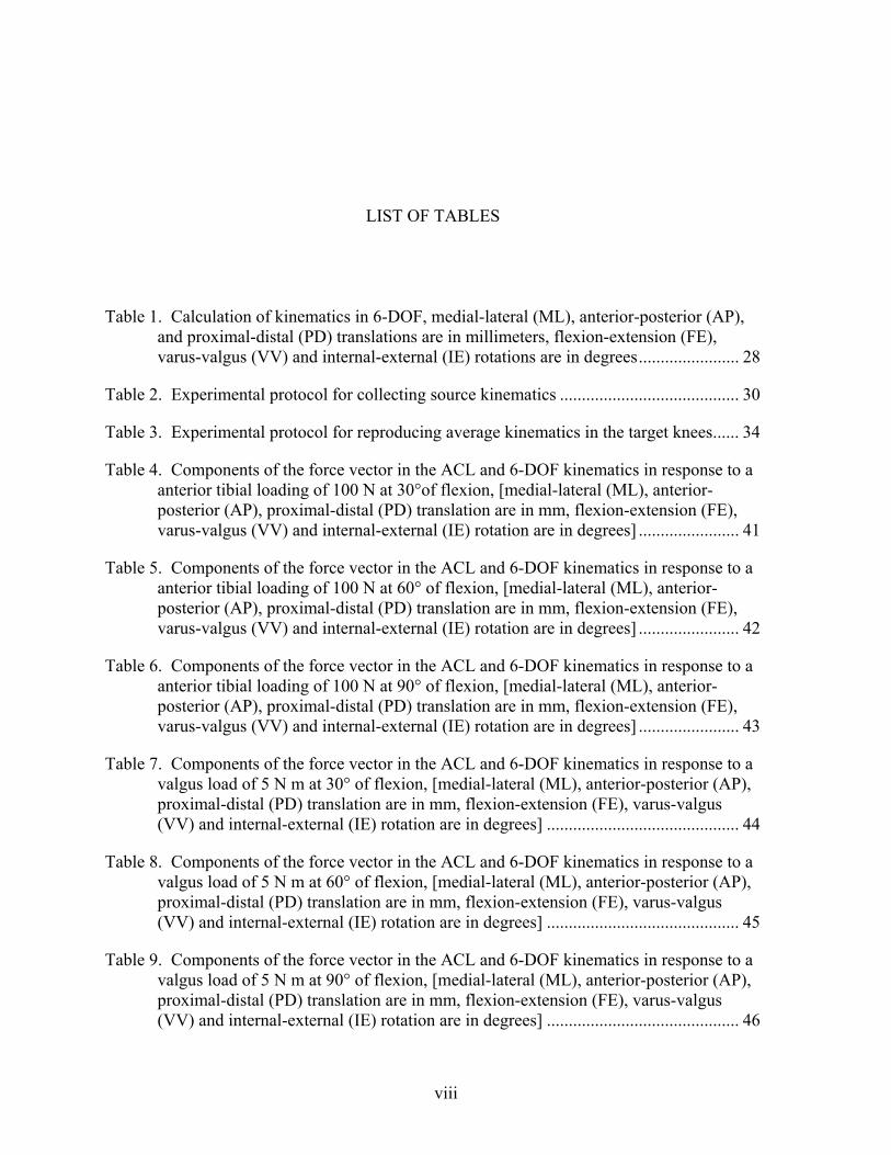
LIST OF TABLES Table 1. Calculation of kinematics in 6-DOF, medial-lateral (ML), anterior-posterior (AP),
and proximal-distal (PD) translations are in millimeters, flexion-extension (FE), varus-valgus (VV) and internal-external (IE) rotations are in degrees....................... 28
Table 2. Experimental protocol for collecting source kinematics ......................................... 30
Table 3. Experimental protocol for reproducing average kinematics in the target knees...... 34
Table 4. Components of the force vector in the ACL and 6-DOF kinematics in response to a anterior tibial loading of 100 N at 30°of flexion, [medial-lateral (ML), anterior-posterior (AP), proximal-distal (PD) translation are in mm, flexion-extension (FE), varus-valgus (VV) and internal-external (IE) rotation are in degrees] ....................... 41
Table 5. Components of the force vector in the ACL and 6-DOF kinematics in response to a anterior tibial loading of 100 N at 60° of flexion, [medial-lateral (ML), anterior-posterior (AP), proximal-distal (PD) translation are in mm, flexion-extension (FE), varus-valgus (VV) and internal-external (IE) rotation are in degrees] ....................... 42
Table 6. Components of the force vector in the ACL and 6-DOF kinematics in response to a anterior tibial loading of 100 N at 90° of flexion, [medial-lateral (ML), anterior-posterior (AP), proximal-distal (PD) translation are in mm, flexion-extension (FE), varus-valgus (VV) and internal-external (IE) rotation are in degrees] ....................... 43
Table 7. Components of the force vector in the ACL and 6-DOF kinematics in response to a valgus load of 5 N m at 30° of flexion, [medial-lateral (ML), anterior-posterior (AP), proximal-distal (PD) translation are in mm, flexion-extension (FE), varus-valgus (VV) and internal-external (IE) rotation are in degrees] ............................................ 44
Table 8. Components of the force vector in the ACL and 6-DOF kinematics in response to a valgus load of 5 N m at 60° of flexion, [medial-lateral (ML), anterior-posterior (AP), proximal-distal (PD) translation are in mm, flexion-extension (FE), varus-valgus (VV) and internal-external (IE) rotation are in degrees] ............................................ 45
Table 9. Components of the force vector in the ACL and 6-DOF kinematics in response to a valgus load of 5 N m at 90° of flexion, [medial-lateral (ML), anterior-posterior (AP), proximal-distal (PD) translation are in mm, flexion-extension (FE), varus-valgus (VV) and internal-external (IE) rotation are in degrees] ............................................ 46

ix
Table 10. Six DOF kinematics in response to an anterior load for 4 porcine knees. [medial-lateral (ML), anterior-posterior (AP), proximal-distal (PD) translation, flexion-extension (FE), varus-valgus (VV) and internal-external (IE) rotation]..................... 48
x
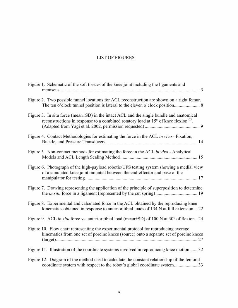
LIST OF FIGURES Figure 1. Schematic of the soft tissues of the knee joint including the ligaments and
meniscus........................................................................................................................ 3
Figure 2. Two possible tunnel locations for ACL reconstruction are shown on a right femur. The ten o’clock tunnel position is lateral to the eleven o’clock position...................... 8
Figure 3. In situ force (mean±SD) in the intact ACL and the single bundle and anatomical reconstructions in response to a combined rotatory load at 15° of knee flexion 65. (Adapted from Yagi et al. 2002, permission requested) ............................................... 9
Figure 4. Contact Methodologies for estimating the force in the ACL in vivo - Fixation, Buckle, and Pressure Transducers .............................................................................. 14
Figure 5. Non-contact methods for estimating the force in the ACL in vivo - Analytical Models and ACL Length Scaling Method .................................................................. 15
Figure 6. Photograph of the high-payload robotic/UFS testing system showing a medial view of a simulated knee joint mounted between the end-effector and base of the manipulator for testing................................................................................................ 17
Figure 7. Drawing representing the application of the principle of superposition to determine the in situ force in a ligament (represented by the cut spring).................................... 19
Figure 8. Experimental and calculated force in the ACL obtained by the reproducing knee kinematics obtained in response to anterior tibial loads of 134 N at full extension ... 22
Figure 9. ACL in situ force vs. anterior tibial load (mean±SD) of 100 N at 30° of flexion.. 24
Figure 10. Flow chart representing the experimental protocol for reproducing average kinematics from one set of porcine knees (source) onto a separate set of porcine knees (target)......................................................................................................................... 27
Figure 11. Illustration of the coordinate systems involved in reproducing knee motion ...... 32
Figure 12. Diagram of the method used to calculate the constant relationship of the femoral coordinate system with respect to the robot’s global coordinate system.................... 33

xi
Figure 13. Anterior tibial translation-ATT (mean±SD) in response to an anterior load of 100 N, n = 8 – (*, p<0.05) ................................................................................................. 36
Figure 14. Valgus rotation (mean±SD) in response to a valgus load of 5 Nm, ..................... 37
Figure 15. In situ force (mean±SD) in the ACL in response to an anterior load of 100 N and average kinematics. (*, p<0.05).................................................................................. 38
Figure 16. In situ force (mean±SD) in the ACL in response to a valgus load of 5 Nm and average kinematics. (*, p<0.05).................................................................................. 39
Figure 17. Load-displacement curve in response to an applied load of 100 N at 90°of flexion – The standard deviation of the toe region is represented on the average curve ........ 50
Figure 18. Differences in internal-external knee laxity in response to a 3 Nm internal and external load throughout knee flexion-extension........................................................ 52

xii
ACRONYMS ACL Anterior Cruciate Ligament AM Anteromedial DOF Degrees of Freedom PL Posterolateral UFS Universal Force Moment Sensor

1
1.0 MOTIVATION
The ACL is the most frequently injured ligament within the knee. This injury affects
roughly one in 3,000 people each year in the United States 1-3. Despite the large number of
ACL reconstructions that are performed every year around the world, these procedures are
neither able to fully restore intact knee kinematics nor fully reproduce the force in the intact
ACL 4-13. The force of the ACL in response to simple loads designed to simulate clinical
exams, such as a pivot shift test or an anterior drawer test, have been quantified in vitro 14-18.
However, the literature provides contradictory and, in many cases, uncertain conclusions as
to the force and function of the ACL in vivo 19-28. In particular, there is little scientific data
available to guide postoperative rehabilitation, which can range from conservative to
aggressive. There is also a lack of clarity as to which rehabilitation exercises and activities
of daily living, i.e. closed chain vs. open chain 22, 28, squat vs. knee extension 23, 24, 28, and
stair climbing vs. walking 25-27, best restore the function of an intact knee postoperatively.
The force data obtained in future studies from reproducing average kinematics will
elucidate how well the ACL graft is performing during various rehabilitation regimens and
activities of daily living. The force data obtained from the ACL reconstructed knee will be
compared to that of the intact ACL – the “true gold standard of ACL reconstruction.” This
information will be used to suggest directions for improvements of ACL reconstruction, not
only in terms of graft fixation and placement but also in terms of postoperative rehabilitation
regimens that are scientifically based. Finally, from reproducing average kinematics, it will
be possible to provide force validation for a realistic computational model of the knee. Once
the model is validated with the experimental data obtained from a high-payload robotic/UFS
testing system, it can be used to determine the forces and force distribution in the ACL in
response to more complex dynamic in vivo activities.
2
2.0 BACKGROUND AND SIGNIFICANCE
First, a brief description of the anatomy and function of the knee and ACL will be
described. Second, biomechanics of the ACL will be discussed. Third, previous
methodologies used to measure in vivo force in the ACL will presented. Next, the
robotic/UFS testing system will be introduced. Finally, preliminary studies, which lead us to
adopt the current methodology for reproducing in vivo kinematics, will be described.
2.1 Anatomy
An understanding of the anatomy of the knee and the ACL are important for
understanding the function of the ACL and for ultimately improving reconstruction
procedures and rehabilitation protocols. This section of the thesis will describe the anatomy
of the knee and ACL. Finally, a review of the most recent findings of the function of the
ACL and its bundles will be discussed.
2.1.1 Anatomy of the Knee
The bones of the knee consist of the femur, tibia, fibula, and patella. The femur is the
longest bone of the body and extends from the hip joint to the knee joint. At the hip joint, the
femoral head fits within the acetabulum, while at the knee joint, the femoral condyles glide
upon the plateau of the tibia. The tibia extends from the knee joint to the talus or ankle. The
fibula runs parallel to the tibia on the lateral side.

3
The patella, a sesamoid bone within the quadriceps and the patellar tendon, glides within the
trochlear groove of the femur and comprises the patellar-femoral joint 29.
The lateral and medial menisci of the knee conform to the surface of the tibial
plateau. The lateral meniscus is circular, while the medial meniscus is more oval. There are
four main ligaments of the knee (Figure 1): the anterior cruciate ligament (ACL), the
posterior cruciate ligament (PCL), the medial collateral ligament (MCL) and the lateral
collateral ligament (LCL). The ACL and the PCL cross over one another inside the joint to
connect the femur to the tibia.
Figure 1. Schematic of the soft tissues of the knee joint including the ligaments and meniscus

4
The ACL is the primary restraint to anterior translation of the tibia with respect to the
femur, while the PCL is the primary restraint to posterior tibial translation. The MCL is
located on the medial aspect of the knee, connecting the femur to the tibia; it primarily
restrains valgus rotation of the tibia. The lateral collateral ligament connects the lateral
aspect of the femur to the head of the fibula and is the primary restraint to varus rotation of
the tibia. The many muscles of the knee provide dynamic stabilization to the knee joint. The
main muscle groups can be divided into those that produce flexion or extension of the knee.
The extensor muscles are known as the quadriceps, which include the rectus femoris, the
vastus medialis, the vastus lateralis, and the vastus intermedius. The flexor muscles are
known as the hamstrings and include the gracilis, semimembranosus, semitendinosus, and
sartorius.
2.1.2 Anatomy of the Anterior Cruciate Ligament
The anterior cruciate ligament is an intra-articular ligament, which means it is located
inside the articular surface of the knee joint. It is also extrasynovial, and therefore located
outside of the synovium, a surrounding protective layer of synovial fluid.
The 3-4 cm long ACL has a cross-sectional area of roughly 37 mm2 at the mid-
substance that varies little with knee flexion 30 The insertion of the ACL expands to 3.5 times
its cross-sectional area at the mid-substance as it directly inserts into the posteromedial
aspect of the lateral femoral condyle and the anteromedial tibial plateau. It is angulated in the
sagittal plane to allow the ACL to function to restrict anterior tibial translation, internal tibial
rotation, and valgus tibial rotation. The semi-circular femoral insertion, longer in the
superior inferior direction than in the anteroposterior direction, has an average cross sectional
area of 113 mm2, while the average cross sectional area of the oval tibial insertion, longer in
the anteroposterior than mediolateral direction, is 136 mm2 31. Blood supplied to the ACL is
shared with the PCL through the middle genicular artery. The nerve supply is also shared
with the PCL using the popliteus plexus of nerves.

5
2.2 Function of the Anterior Cruciate Ligament
The function of diarthrodial joints is mediated by the complex interactions of bones,
ligaments and capsule, articular cartilage, and muscle. The interdependence of these
structures is such that severe injury or failure of any one of them can lead to deterioration of
the others and then the disruption of overall joint function. Ligaments are particularly
vulnerable with estimates of the annual rate of ligament injury in North America ranging
from 5-10% of all people up to the age of 65 years 32. Injuries to these soft tissues include
frequent sprains as well as complete rupture.
The ACL has been shown to resist excessive anterior tibial translation (ATT), as well
as internal and valgus rotation 14, 33-37. The force distribution in the ACL can be defined as
the percentage of load sharing between the two functional bundles of the ACL. The ACL
consists of two main bundles, the anteromedial (AM) bundle, and the posterolateral (PL)
bundle. The posterior lateral bundle has higher forces with knee extension, while the anterior
medial bundle will carry a higher percentage of the forces with knee flexion. The larger,
shorter AM bundle is generally taut during passive knee flexion, while the PL bundle is
relatively taut in passive knee extension 14, 38. Both bundles of the ACL carry load during
valgus rotation at 15° and 30° of knee flexion 38.
The anterior tibial translation and in situ force in the ACL were also examined
following the application of a 200 N compressive as well as a 100 N AP load 39. These
loading conditions resulted in a decrease in the total anterior-posterior tibial translation and a
significant increase in the anterior tibial translation coupled with an even smaller decrease in
the posterior tibial translation. High compressive loads in the knee cause elevated in situ
forces in the ACL, suggesting that high axial compressive loads to the knee without muscle
contraction should be avoided during rehabilitation.

6
2.3 Biomechanics of the ACL
Ligaments are highly specialized connective tissues that connect bones and transfer
forces to mediate smooth movement of diarthrodial joints during normal activities. They also
limit excessive displacements between the bones at high external loads. Ruptures of
ligaments due to excessively high loads experienced during sports and accidents can upset
the dynamic balance between the mobility and stability of a joint and result in abnormal
kinematics. This can potentially cause damage to other soft tissues of the joint and
eventually lead to pain, morbidity, and osteoarthritis.
For young and active individuals participating in sports activities, the anterior cruciate
ligament (ACL) of the knee is especially susceptible to frequent injury. Most ACL tears do
not heal and require surgical reconstruction 40, 41. The results of surgical reconstructions are
generally successful and most patients can resume normal activities and return to
participating in sports 42, 43. However, 15-25% of patients have experienced less than
satisfactory results at both short and long-term follow-ups 8, 44-47. While there are numerous
factors that contribute to these failures, recent biomechanical studies have helped to gain a
better understanding of the complex function of the ACL as well as the function of its
replacement grafts. There are also ongoing studies such as this thesis that aims to further
enhance this knowledge in order to improve outcomes for patients.
2.3.1 ACL Reconstruction
In spite of the large number of ACL reconstructions that are performed each year
around the world (estimated between 75,000 to 100,000 cases in the United States alone),
these procedures continue to encounter post-operative problems 48. Recent literature on long-
term follow-up between five and ten years has revealed that 15 – 25% of patients have
unsatisfactory results 8, 11, 13, 35. In terms of ACL surgery, there is much debate over the use
of different autographs 49-54, the selection of fixation devices 8, 55-61, and tunnel placement42,
62, 63.

7
Our research has found that current ACL reconstruction procedures are insufficient in
resisting rotatory loads applied to the knee and that the medial meniscus plays an important
role in ACL reconstructions.
A 134 N anterior tibial load applied to an ACL-reconstructed knee with a quadruple
semitendinosus/gracilis tendon (QSTG) graft and a bone-patellar tendon-bone (BPTB) graft
showed anterior tibial translation (ATT) of 166±33% and 140±32% of the intact knee,
respectively. When the same grafts were subjected to a combined internal tibial torque of 10
N-m and valgus torque of 10 N-m, the ATT was 192±52% and 171±48% of the intact knee,
respectively. The results demonstrated that both reconstructions were successful in limiting
anterior tibial translation under anterior tibial loads. However, in response to a combined
rotational load, neither of the two reconstructions were effective in reducing anterior tibial
translation. The placement of the QSTG and BPTB graft between the AM and PL bundles
made them incapable of providing rotatory stability because they were close to the rotational
center of the knee 4. Furthermore, the mean in situ forces in the grafts under a 134-N anterior
tibial load were restored to within 78% to 100% of that in the intact knee.
8
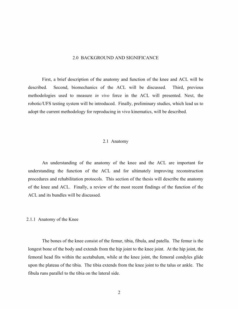
Figure 2. Two possible tunnel locations for ACL reconstruction are shown on a right femur. The ten o’clock tunnel position is lateral to the eleven o’clock position
Thus, a study of the effectiveness of moving the tunnel laterally and away from the
rotational center of the knee to improve the function of the ACL graft was performed 64. A
BPTB graft was placed in the femoral tunnel at the 10 and 11 o’clock positions (Figure 2).
The 10 o'clock position approximates the femoral insertion site of the PL bundle of the ACL
while the 11 o’clock position is close to the insertion site of the AM bundle. In response to
an anterior tibial load, there were no significant differences in ATT or in situ forces between
the intact and reconstructed knee for both the 10 and 11 o’clock positions. However, under
rotatory loads, there was significantly higher ATT in the reconstructed knees. The in situ
force in the replacement graft fixed at the 10 o’clock position was significantly higher than
the in situ force in the graft fixed at the 11 o’clock position. These results indicate that,
under rotatory loads, the 10 o’clock position restores function more effectively than the 11
o’clock position, but neither position has been shown to restore the knee to its intact state.

9
Therefore, it is believed that in order to restore the function of both bundles of the
ACL, it may be necessary to consider a more anatomical reconstruction. Using a QSTG
graft, both the traditional and anatomical reconstructions were studied 65. For the anatomic
reconstructions, one tibial tunnel and two femoral tunnels, based on the insertion sites of the
ACL bundles, were used. It was found that the anatomically reconstructed knee had
significantly lower ATT than the single bundle reconstruction (with femoral tunnel at 11
o’clock). However, both the traditionally and anatomically reconstructed knees experienced
significantly higher ATT than the intact knee. The anatomically reconstructed knee better
restored the in situ force of the intact ligament than the traditionally reconstructed knee
(Figure 3).
Figure 3. In situ force (mean±SD) in the intact ACL and the single bundle and anatomical reconstructions in response to a combined rotatory load at 15° of knee flexion 65. (Adapted from Yagi et al. 2002, permission requested)
Flexion Angle (degrees)
In S
itu F
orce
(N)

10
Thus, it has been shown that an anatomic ACL reconstruction replacing both the
anteromedial (AM) and posterolateral (PL) bundles could restore normal knee kinematics
and in situ force of the ACL more closely than the popular single-bundle reconstruction
procedures when the graft is placed at the 11 o’clock femoral tunnel position65. In addition,
it was demonstrated that using a single ACL graft placed at the 10 o’clock femoral tunnel
position is more effective in resisting rotatory loads than those at the 11 o’clock position 66.
Therefore, the objective of the following study was to compare two reconstruction
procedures, i.e. anatomic vs. a more lateral graft placement at 10 o’clock femoral tunnel
position, which is close to the insertion site of the PL bundle. A 134 N anterior tibial load at
knee flexion angles of full extension (FE), 15°, 30°, 60° and 90° and a combined rotatory
load of 10 N-m valgus and 5 N-m internal tibial torque at knee flexion angles of 15° and 30°
were applied to knees with both the single-bundle reconstruction placed at 10 o’clock
position on the femoral side and the double-bundle anatomical reconstruction. Results
demonstrated that under anterior loading the anatomic double-bundle reconstruction restored
intact knee kinematics and in situ force more closely than 10 o’clock single-bundle
reconstruction, especially at high flexion angles. However, in response to rotatory loads, 10
o’clock single-bundle reconstruction was as effective at restoring intact knee kinematics and
in situ force as the anatomical reconstruction. Because the 10 o’clock femoral tunnel
position is close to the PL bundle insertion and is located more laterally than the 11 o’clock
position, it contributes to the rotatory stability of the knee. Since the PL bundle is maximally
taut at low flexion angles, the 10 o’clock single-bundle reconstruction could not restrain the
ATT at high flexion angles. The anatomic double-bundle reconstruction more successfully
restored intact knee kinematics and in situ force than 10 o’clock single-bundle reconstruction
at high flexion angles, but these differences may not be clinically significant 67.
The resultant force in the meniscus was found to be significantly elevated in ACL
deficient knees in response to a 134 N anterior tibial load with 200 N of axial compression.
After ACL reconstruction, these forces returned to intact levels. Conversely, with medial
meniscectomy, the in situ force in the ACL graft increased by approximately 50%. Thus, the
ACL and medial meniscus are interdependent. The medial meniscectomy may cause the
ACL graft to fail because of excessive force in the graft 68.

11
Another study focused on the role of the posterior horn of the medial meniscus (PMM) by
removing portions of the PMM and its effect on knee kinematics in response to a 10 N-m
varus torque. The results suggest that removing one-third of the PMM will have little effect
on knee kinematics while removing more than two-thirds of the posterior horn of the medial
meniscus will have a significant effect on the kinematics of the knee. Based on these results,
removal of one-third of the posterior horn of the medial meniscus may present little risk to
the ACL. However, one needs to give serious consideration to the potential risk to other
knee structures69. These studies indicate the importance of the medial meniscus on
restraining knee motion, which will minimize loads transferred to the ACL and other
structures of the knee.
The biomechanical analyses of the ACL-reconstructed knees based on cadaveric
studies have helped us understand the complexity of the ACL. However, from this series of
studies, it is clear that there are many complex issues involved with ACL reconstructions. As
the loading conditions applied in these studies are relatively simple and only designed to
mimic clinical exams, more realistic in vivo loading conditions will need to be added in order
to better understand both the function of the intact ACL and the effectiveness of ACL
reconstruction. The new scientific data obtained from in vivo loading will enable a more
thorough evaluation of the function of ACL replacement grafts, improve reconstruction
procedures, and guide rehabilitation protocols 5, 22, 25, 70-77.
2.3.2 Rehabilitation Protocols
The quadriceps muscle of patients who undergo ACL reconstruction becomes
significantly weakened following surgery 78, 79. Various postoperative rehabilitation exercises
are used to restore quadriceps strength in order for patients to return safely to their previous
activities. Some researchers have suggested that closed kinetic chain exercises (closed-
chain) rather than open kinetic chain exercises (open-chain) are better at protecting the ACL
replacement graft from excessive force 80, 81.

12
However, the University of Vermont group 77 recently reported that there were only minor
differences in the strain values in the ACL replacement graft obtained during closed- and
open-chain exercises. Furthermore, in a prospective randomized clinical study, a combination
of closed-chain and open-chain training after ACL reconstruction was found to improve
patients’ quadriceps strength significantly over closed-chain exercises alone 6. In a more
recent study utilizing subjects who frequently lifted weights, an analytical model found that
neither closed nor open chain exercises created forces high enough to predispose the ACL
graft to premature failure with the exception of the last 25° of extension for open-chain
exercises 28. Nevertheless, the force distribution of the ACL replacement graft during these
exercises is still unclear 23, and the need for further data on rehabilitation exercises that
involves tibial rotatory motion has been suggested 82, 83.
The University of Vermont group has ranked various rehabilitation exercise protocols
based on in vivo strains in the AM bundle of the intact ACL from patients 25, 77, 84, 85. A
similar study whereby the forces in the ACL replacement graft are obtained will further the
understanding of ACL replacement graft function in response to these rehabilitation
exercises. Whether the ACL replacement graft experiences excessive forces during these
exercises, which could predispose it to failure during the early healing process, remains
unknown 9, 23, 85-90. Therefore, it is critical to quantify the level of forces in the ACL
replacement graft during these activities. The methodology described in this thesis will
enable identification of the difference between the in situ force and force distribution of the
ACL and ACL graft during these rehabilitation exercises. This knowledge will help surgeons
and physical therapists select appropriate post-operative rehabilitation protocols on a
scientific basis. Moreover, rehabilitation exercises could be designed to strengthen the
quadriceps muscles as well as to maintain adequate in situ forces in the ACL graft for healing
and remodeling that could lead to improved knee function after ACL reconstruction.
13
2.4 Previous Attempts to Estimate In Vivo Force
During the last decade, intensive efforts have been made to quantify the forces in the
ACL in vivo19-21, 91, 92. As a result, various devices and methods have been developed to
measure the force in the ACL, including buckle, femoral fixture and pressure transducers,
analytical models and ligament scaling methods. With the use of these devices, valuable
information on forces experienced by the ligaments has been obtained. However, each of
these devices has limitations. Many of these methods have been contact methodologies that
may affect the force measured in the ACL by altering the ligament’s structure and
environment.
2.4.1 Invasive – Contact Methodologies
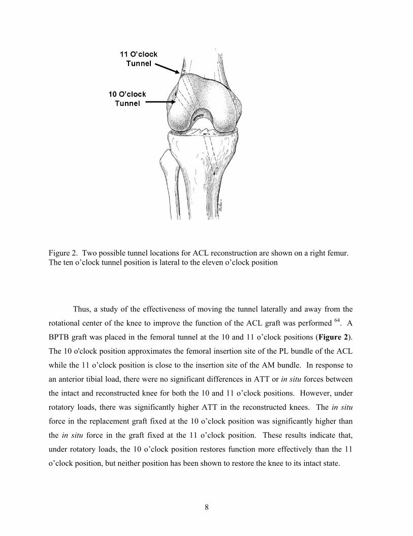
Contact methodologies such as fixation, buckle, and pressure transducers have been
used to measure force in the ACL (Figure 4). The fixation transducer relates tension in the
ACL graft to strain caused by the deflection of a cantilever beam within the transducer91, 92.
Buckle transducers measure the force in the ACL by relating strain caused by the deflection
of the transducer to tension in the ACL19, 20. Pressure transducers are surgically implanted
within one of the functional bundles of the ACL relating pressure to force21. These devises
are invasive and requiring surgical installation. In addition, impingement and decreases in
force due to healing often occur when the force transducers are placed within the joint20, 92 .
Finally, force transducers are impractical for estimating force in vivo in human subjects
because most devices must be calibrated in vitro19, 21.

14
Figure 4. Contact Methodologies for estimating the force in the ACL in vivo - Fixation, Buckle, and Pressure Transducers 2.4.2 Noninvasive – Non-Contact Methodologies
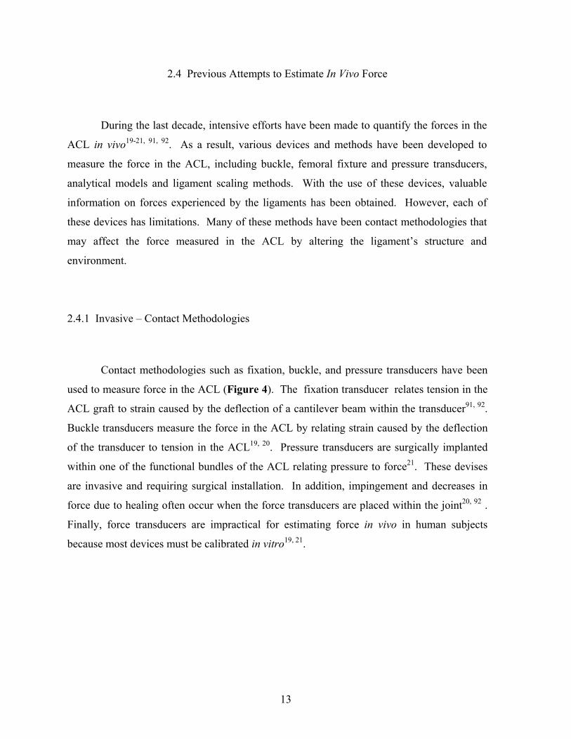
Although few in number, there have been previous attempts to develop noninvasive,
non-contact methodologies to estimate the force in the ACL. Analytical models have been
used to estimate force in the ACL (Figure 5). The major limitation of these analytical
models is the difficulty of validating these models experimentally23, 24, 26, 28, 93. Previous
researchers have also attempted to estimate forces in the ACL through a ligament scaling
method. The location of the ACL origin and insertion were predicted by mathematically
transforming their location from a dissected cadaveric specimen to their respective position
in human subjects 94. These transformations between the ACL origin and insertion were
based on anatomical landmarks, which were located by palpation on human subjects. This
methodology, although non-invasive and non-contact, was not effective in human subjects
due to the difficulty in interpretation and precision of defining anatomical landmarks in vivo.
15
Figure 5. Non-contact methods for estimating the force in the ACL in vivo - Analytical Models and ACL Length Scaling Method
2.5 Robotic/UFS Testing System
In our research center, we have successfully used a 6-DOF robotic manipulator in
combination with a 6-DOF UFS to measure the in situ force in ligaments 95-100. The
advantages of this innovative method are based on the robotic manipulator reproducing
positions of the path of knee motion with high fidelity such that the principle of superposition
can be employed to calculate changes in force before and after a ligament is transected 95, 98.
Further, the in situ force in the ACL is determined without dependence on the specimen
geometry, the location of the ligament, or muscle forces and without having a device
physically in contact with the ligament. This system is capable of measuring the force and
force distribution in the ACL and other soft tissue structures in the same knee specimen, thus
eliminating inter-specimen variability and increasing statistical power.

16
Our research has provided quantitative data on forces and force distribution in both the AM
and the PL bundles of the ACL as well as ACL replacement grafts during the anterior drawer
test, Lachman test, and simulated pivot shift test using human cadaveric knee specimens 38, 98,
101-103. In the future, this testing system will be used to reproduce knee kinematics. This
thesis is devoted to the partial development of a methodology to estimate the in situ force in
the ACL by reproducing average kinematics.
2.5.1 Experimental Evaluation of Joint Function
In our research center, two testing systems have been developed that consist of a
robotic manipulator combined with a universal force-moment sensor 95, 97, 98, 104. The low-
payload robot (Mitsubishi Electric Corporation, RV-MIS-P2, Nagoya, Aichi, Japan
UNIMATE Puma 762) is capable of applying loads up to 300 N while the high-payload
manipulator (S-900W, FANUC Robotics North America, Inc, Auburn Hills, MI) can exert
loads of 3500 N or more (Figure 6). These testing systems allow for multiple axial force and
position controls that can be used to apply loads and produce motions of diarthrodial joints in
multiple degrees-of-freedom (DOF). The robotic/UFS testing system defines a passive path
of flexion extension of the joint. The passive path is the joint motion resulting in zero forces
and moments; it serves as a reference position for other loading conditions. In addition, each
testing system can record the resulting 6-DOF motions and then reproduce the identical path
of motion in a dissected specimen, allowing for the use of the principle of superposition.
Since identical loading conditions are applied to the intact and dissected states of the same
joint specimen, inter-specimen variability can be minimized and the statistical power
increased in each study.
In addition to a brief review of our current development of knee kinematics, the
description and control of joint motion and forces/moments with respect to an anatomical
reference system for clinical relevance will be described. This includes the determination of
the transformations between the axes of all coordinate systems as well as forces in the
ligaments of the knee using a non-contact methodology.

17
Figure 6. Photograph of the high-payload robotic/UFS testing system showing a medial view of a simulated knee joint mounted between the end-effector and base of the manipulator for testing
2.5.2 Kinematics of the Robotic Manipulator
A robotic manipulator is a tool that can control the location and orientation of its end
effector relative to its base (Figure 6). This enables the robot to accurately control the
location and orientations of an object attached to its end effector and record each location and
orientation throughout a path of motion 95. This can be accomplished using a 4x4-
transformation matrix (T) that is composed of rotation (R) and translation components (U),
such as the two matrices below:
UFS
Simulated knee Joint

18
∆∆∆
=
1000100010001
10 z
yx
U
−
=
1000010000cossin00sincos
10
θθθθ
R (1)
Therefore, the transformation from one link of a multi-link system to another for a serial
robot is a combination of these two components. Where the order of operation is translation
(U) followed by rotation (R)
∆∆∆−
=
10001000cossin0sincos
10 z
yx
Tθθθθ
(2)
and
11PTP oo = (3)
The robot can then determine the location (Po) of its end effector or initiate a desired
motion using a series of transformations between the end effector and the global coordinate
systems. Po can be described as follows for a six link system 105, 106.
665
54
43
32
21
1oo PTTTTTTP = (4)
2.5.3 Application of External Loads to Joint (Force Control)
Once the transformations between the sensor and axes of the joint coordinate system
have been established, the application of specified external loads to the knee joint is
straightforward using the robotic/UFS testing system. Force (or load) control is used to
apply a given external load, or a set of desired forces and moments to the joint. This mode of
control is similar to the flexibility method commonly described in the literature 107. The
desired movement of the robotic manipulator is determined by comparing the current forces
and moments measured by the UFS to the specified, or target, forces and moments. The
robot is then instructed to perform a movement in order to achieve the target forces and
moments and the new forces and moments are recorded.

19
Based on the differences between the target forces and moments and the new forces and
moments measured by the UFS, a new movement is calculated and the robot is instructed to
move the joint accordingly. This iterative process allows the testing system to move the knee
through the appropriate motions such that the specified loads are developed within the joint.
The testing system can apply an identical external force to a specimen in both the
intact and ligament-deficient states in force control mode. The difference in the kinematics
between the intact and ligament-deficient states can then be determined. These tests are
similar to clinical examinations used to diagnose ligament deficiency where the clinician
applies a similar load to the uninjured and injured knee to compare the differences in
resulting kinematics for diagnostic purposes.
Figure 7. Drawing representing the application of the principle of superposition to determine the in situ force in a ligament (represented by the cut spring)
Robot Arm
Robot Arm
UFS
CCuutt
UFS
F1 F2

20
2.5.4 In Situ Forces in Ligaments (Position Control)
A detailed understanding of a ligament’s function and contribution to overall joint
kinematics is dependent on an accurate determination of the in situ forces developed in the
ligament in response to motion or external loading of the intact joint (Figure 7).
To accomplish this task, the robotic/UFS testing system is asked to accurately reproduce joint
positions (position control). This testing system is capable of not only reproducing the joint
positions at the maximum loads but at each intermediate position used to reach the extreme
position as well. Therefore, any sequence of joint positions that represents the path of
motion of a diarthrodial joint can be reproduced. To determine the in situ force in a ligament
(e.g. ACL) a known external load (F1) is applied to an intact knee and the resulting motion is
recorded. The ACL is subsequently transected (as represented by the cut spring in (Figure 7)
and the robot reproduces the previously recorded joint motion and a new set of force data
(F2) is obtained; because the path of motion for both test conditions is identical, the principle
of superposition can be applied and the in situ force of the ACL is the vector difference in
recorded forces, i.e. (F1 - F2).
The principle of superposition states that “the combined effect of a number of forces
acting on a structure is equal to the sum of the effects of each force applied separately” 97.
Three assumptions are required to apply the principle of superposition. First, the bones must
be effectively rigid when compared to the soft tissues at the joint. This condition stipulates
that the joint is free from any disease such as osteoporosis, which might significantly
compromise rigidity. Second, no interactions can exist between the surrounding tissues and
the bones. Third, the position of the bones before and after transecting a joint structure must
also be repeated exactly (the position of the tibia must be exactly the same with respect to the
femur). Soft tissue stress strain curves are nonlinear as a result of their viscoelastic behavior.
Even though the stress-strain curve of soft tissues is nonlinear, the principle of superposition
still holds when there is no interaction between the surrounding tissues and the bones as
stated above. Nonlinearity is not a condition for exemption although it could indicate
interaction.
21
As stated before, the UFS is capable of measuring three forces and three moments along
and about a Cartesian coordinate system fixed with respect to the sensor.
Tzyxzyx
s )m,m,m,f,f,f(F = (15)
The magnitude of the external forces can be determined by:
(16)
The direction of the external forces can also be determined as follows:
222222222,,
zyx
zz
zyx
yy
zyx
xx
fff
fa
fff
fa
fff
fa
++=
++=
++= (17)
where ax, ay and az represent components of the direction vector, a, of the external force.
2.6 Previous Studies at MSRC/Preliminary Studies
Several preliminary studies were performed in the process of developing our current
methodology to estimate ligament force. These studies laid the groundwork for the
methodology presented in this paper.
2.6.1 Computational Models
A 3-D computational model has been used to investigate the effect of variation in
geometric, mechanical, and structural properties between cadaveric knees on the
determination of force in the human ACL during the reproduction of knee kinematics. Ten
human cadaveric knee specimens were tested using the robotic/UFS testing system to
determine the knee kinematics and in situ force in the ACL under an anterior tibial load.
222zyx fffMagnitude ++=

22
The kinematics of each knee was used as input into a validated 3-D finite element model of
the ACL, and forces in the ACL for each knee were calculated. Experimental and calculated
ACL forces were then compared.
Figure 8. Experimental and calculated force in the ACL obtained by the reproducing knee kinematics obtained in response to anterior tibial loads of 134 N at full extension Calculated forces in the ACL varied from the experimental in situ force of the ACL by
2.6±5.2 N (Figure 8). In response to the kinematics obtained under a 134 N anterior tibial
load, the maximum force difference was 3.5%. This data showed that differences in
kinematics due to variation in geometric, mechanical and structural properties between knees
does not have a significant effect on the estimation of force in the human ACL in response to
anterior tibial loads at full extension108.
0 20 40 60 80
100 120
9 29 49 69 89 109 129
Anterior Tibial Load (N)
Calculated (n=10)
Experimental (n=10)
AC
L In
Situ
For
ce (N
)

23
This model did not include joint contact. Preliminary studies at the musculoskeletal research
center have shown that variation in geometric, mechanical and structural properties does
effect the joint compressive force when knee kinematics are reproduced.
2.6.2 Reproducing Kinematics
Preliminary studies have shown that the biological variability between knees creates
high joint contact forces in the knee making it impossible to simply reproduce absolute
motion from one knee onto another. In order to reproduce knee kinematics between different
knees, we needed to choose a common reference position to apply kinematics. The passive
path of flexion extension can be easily recorded from patients and is a safe reference position
from which to apply load. Kinematics were then calculated from the one knee (source) as the
difference between 6-DOF kinematics from the applied loads and the passive path of flexion-
extension109. Kinematics from one cadaveric porcine knee was then added to the specimen
specific reference position of another cadaveric porcine knee. This method proved
unsuccessful due to variation in coupled motions between knees. These differences in
coupled motion damaged the cadaveric porcine knee on which the kinematics were
reproduced.
2.6.3 Reproducing Average Kinematics
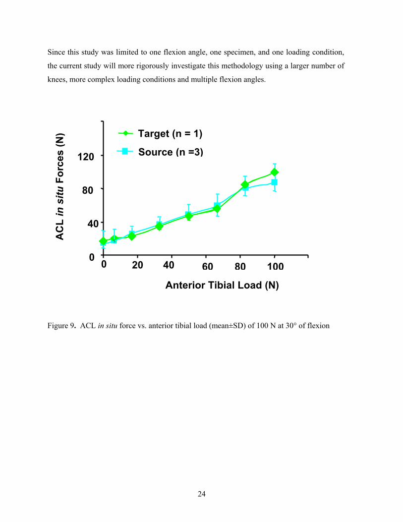
In a preliminary study, average kinematics from three cadaveric porcine knees
(source) were reproduced onto another cadaveric porcine knee (target) at 30° of knee flexion
in response to a 100 N anterior load (Figure 9). The in situ forces in the ACL were not
statistically different (p<0.05), which indicates that it is possible to reproduce kinematics of
one set of knees to obtain in situ forces in another.
24
Since this study was limited to one flexion angle, one specimen, and one loading condition,
the current study will more rigorously investigate this methodology using a larger number of
knees, more complex loading conditions and multiple flexion angles.
Figure 9. ACL in situ force vs. anterior tibial load (mean±SD) of 100 N at 30° of flexion
160
20 0
40
80
120
0 40 60 80 100
AC
L in
situ
For
ces
(N)
Source (n =3)
Target (n = 1)
Anterior Tibial Load (N)
25
3.0 OBJECTIVES
In this section, the overall goal and clinical relevance of this study will be presented. The
specific aims for reproducing in vivo kinematics will also be explained. In section 4.0 the
development of a methodology for estimating the force in the ACL in a non-contact and non-
invasive manner by reproducing average kinematics will be presented.
3.1 Broad Goal
It continues to be the belief of our research center that, for a successful short and
long-term outcome, the ACL replacement graft must restore, as closely as possible, the intact
knee kinematics, and reproduce the force of the intact ACL in response to in vivo activities.
Thus, the broad goal of this work is to improve ACL reconstruction procedures by restoring
the in situ force of the ACL graft to that of the intact ACL during in vivo activities this will
allow rehabilitation protocols to be designed to replicate the knee kinematics and in situ
forces of the intact ACL in vivo.

26
3.2 Specific Aim
The specific aim of this study was to evaluate the feasibility of a non-invasive, non-
contact methodology for estimating force in the ACL by reproducing average kinematics in
6-DOF degrees of freedom from one set of porcine knees (source) onto a separate set of
porcine knees (target). To do this we will:
a) Record Input kinematics from a set of source knees
b) Compute the average kinematics
c) Reproduce these kinematics on a set of target knees
d) The in situ force in the ACL between the applied loads in the source knees and
reproduced kinematics in the target knees will then be compared

27
4.0 METHODS
Figure 10. Flow chart representing the experimental protocol for reproducing average kinematics from one set of porcine knees (source) onto a separate set of porcine knees (target)
4.1 Overview of Methods A robotic/universal force-moment sensor (UFS) testing system was utilized to
determine the passive path of flexion-extension of the source knees (n=8) (Figure 10).
These joint positions served as a reference positions for the application of external loading
conditions to the joint and resulted from minimizing the forces and moments during flexion-
extension of the knee. Source kinematics were then collected in response to an anterior load
of 100 N and a valgus load of 5 Nm at 30°, 60°, and 90° of knee flexion.
SOURCE KNEES TARGET KNEES
Reference Positions (RP)
Remove ACL Reproduce Kinematics
ACL In Situ Force
Reference Positions (RP)
Remove ACL Reproduce Paths of Motion
ACL In Situ Force
Applied Loads Record Kinematics (Kin)
RP + Kin = Paths of Motion (n = 8)
Applied Loads Record Kinematics (Kin)
Remove ACL Reproduce Kinematics
ACL In Situ Force
Avg

28
After the kinematics were collected for eight source knees, the average kinematics were
calculated (Table 1). Next, the ACL was removed and the kinematics from the applied loads
were repeated to determine the in situ force in the ACL for the source knees.
Table 1. Calculation of kinematics in 6-DOF, medial-lateral (ML), anterior-posterior (AP), and proximal-distal (PD) translations are in millimeters, flexion-extension (FE), varus-valgus (VV) and internal-external (IE) rotations are in degrees
The passive path of flexion-extension (reference positions) was subsequently determined for
the target knees. Target kinematics were then collected in response to the same loading
conditions. The reference positions of the target knee and the average kinematics from the
source knees for each loading condition was defined as the paths of motion to be reproduced
on the target knees. After removing the ACL, the calculated paths of motion and target
kinematics were repeated providing the in situ force in the ACL from the average kinematics
of the source knees and the applied loads.
10.0 -0.8 0.0 -0.16.22.9 Average Kinematics
0.1 0.5 30.0-0.31.2-0.5Passive Path (Source) 10.1 -0.3 30.0-0.47.42.4 Source Kinematics – A or B
IE VV FE PD AP ML
mm degrees

29
4.2 Collection of Source Kinematics
The robotic/UFS testing system is designed to test human knees, thus, several
changes to the robot control algorithms were required in order to adapt it to testing porcine
knees. Porcine knees are very lax in internal external rotation. On our first preliminary test,
in which IE loading of 10 Nm was attempted, the robot control algorithm diverged at 90° of
knee flexions breaking the knee; as a result, the IE loading condition was discarded. On the
second preliminary test, the robot control algorithm again diverged at 90° of knee flexion
during passive path. To remedy this problem, the IE moment targets for minimizing IE
rotations during passive path was decreased by an order of magnitude. This change to the
control algorithm minimized the range of IE rotation over which the control algorithm
searches for equilibrium. These changes demonstrated very repeatable passive paths and
prevent further specimen damage. IE laxity continued to pose a problem during AP loading;
IE rotations differed from extreme internal (45°) to extreme external (30°). To prevent this,
IE rotations were limited to ±10° of the reference position at each flexion angle were loads
were applied. Thus, altered passive path (Flex17p.v2) and loading (Load19p.v2) control
algorithm were created. Source kinematics were collected with the successful completion of
these control algorithms.
Six-DOF source kinematics were collected from eight cadaveric porcine knees using
the robotic/UFS testing system. The porcine model was selected because of the similarity
between the human and porcine ACL force magnitude and direction in response to an
anterior load110. Source kinematics were then collected in response to an anterior load of 100
N and a valgus load of 5 Nm at 30°, 60°, and 90° of knee flexion. (Table 2). Only the knee
flexion angle was constrained during anterior loading; hence, this loading condition was a 5-
DOF test. Knee flexion angle and internal-external tibial rotation were constrained during
valgus loading; thus, this loading condition was a 4-DOF test. The robotic/UFS testing
system applies loads in incremental steps, where each incremental step is a percentage of the
target load. There are nine loading steps, which ramp up to meet the force targets in the
anterior and valgus direction (100 N, 5 Nm).

30
Therefore, the load and displacement is recorded for nine positions between the reference
position and the position of maximum target load. The loading conditions resulted in
Kinematics – 1A for anterior loads and Kinematics – 1B for valgus loads. The ACL was
then transected and Kinematics 1A & 1B were repeated on the ACL deficient knee. The
difference between the knee forces in the intact and the ACL deficient knee is attributed to
the ligament, giving the in situ force in the ACL by the principle of superposition.
Table 2. Experimental protocol for collecting source kinematics Protocol Data Obtained Intact knee
Passive path of flexion-extension Reference positions Applied loads at 30°, 60°, and 90°
Anterior load of 100 N Kinematics - 1A Valgus load of 5 Nm (4-DOF) Kinematics - 1B
ACL –deficient knee Reproducing kinematics – 1A, 1B ACL in situ force
4.3 Calculation of Average Kinematics – Source Knees
The 6-DOF kinematics for an applied load were calculated by taking the difference
between Kinematics 1A & 1B and the reference positions in each of the 6-DOF. The
kinematics in 6-DOF were then calculated by taking the average of the kinematics of the
eight source knees tested (Table 1). One set of average kinematics was calculated for each
loading condition (Anterior load of 100 N, valgus load of 5 Nm) at 30°, 60°, and 90° of
flexion, giving a total of six paths of motion to be reproduced in the target knee.
31
4.4 Reproducing 6-DOF Average Kinematics – Target Knees
The low-payload robotic/UFS testing system moves the tibial with respect to its
global coordinate system in response to the force feedback during a force control. The robot
records the location of the tibia in Cartesian coordinates, x, y, z, translations and nautical
angles yaw, pitch, and role. The robot does not record the relationship between the tibia and
femur but does not utilize this relationship to carry out joint motion. Thus, the user can
request the Cartesian Coordinates of the tibia with respect to the global coordinate system
and the joint motion (tibia with respect to femur). Average kinematics are calculated based
on the joint motion but the robot cannot utilize the joint motion because the position and
orientation of the tibia is unique for each test. Therefore, given the average joint motion and
the position and orientation of the femur with respect to robot global, the motion of the tibia
with respect to the robot’s global coordinate system can than be calculated (TG_T)
(Figure 11).
32
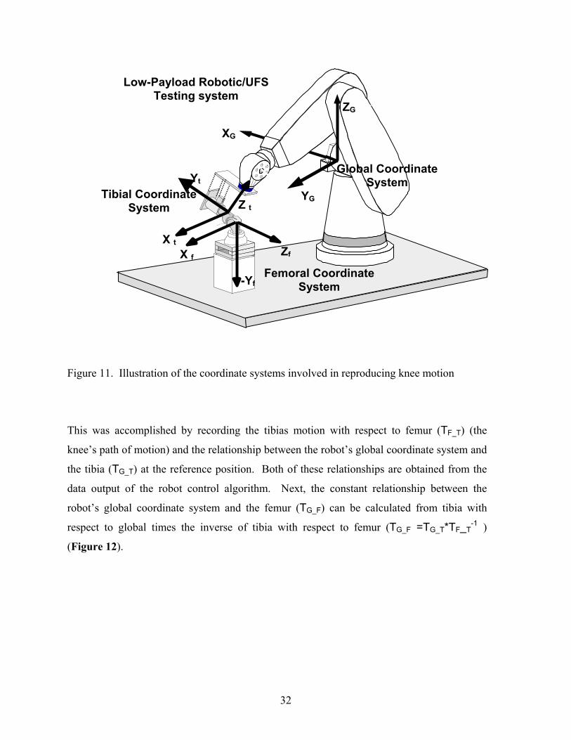
Figure 11. Illustration of the coordinate systems involved in reproducing knee motion
This was accomplished by recording the tibias motion with respect to femur (TF_T) (the
knee’s path of motion) and the relationship between the robot’s global coordinate system and
the tibia (TG_T) at the reference position. Both of these relationships are obtained from the
data output of the robot control algorithm. Next, the constant relationship between the
robot’s global coordinate system and the femur (TG_F) can be calculated from tibia with
respect to global times the inverse of tibia with respect to femur (TG_F =TG_T*TF_T-1 )
(Figure 12).
Joint 5
Joint 4 ZG
YG
XG
Global Coordinate System
Low-Payload Robotic/UFS Testing system
Femoral Coordinate System -Yf
X f Zf
Tibial Coordinate System Z t
Yt
X t
33
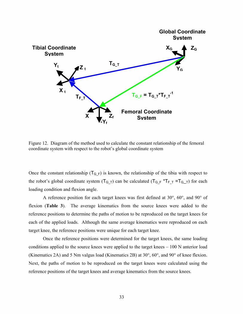
Figure 12. Diagram of the method used to calculate the constant relationship of the femoral coordinate system with respect to the robot’s global coordinate system
Once the constant relationship (TG_F) is known, the relationship of the tibia with respect to
the robot’s global coordinate system (TG_T) can be calculated (TG_F *TF_T =TG_T) for each
loading condition and flexion angle.
A reference position for each target knees was first defined at 30°, 60°, and 90° of
flexion (Table 3). The average kinematics from the source knees were added to the
reference positions to determine the paths of motion to be reproduced on the target knees for
each of the applied loads. Although the same average kinematics were reproduced on each
target knee, the reference positions were unique for each target knee.
Once the reference positions were determined for the target knees, the same loading
conditions applied to the source knees were applied to the target knees – 100 N anterior load
(Kinematics 2A) and 5 Nm valgus load (Kinematics 2B) at 30°, 60°, and 90° of knee flexion.
Next, the paths of motion to be reproduced on the target knees were calculated using the
reference positions of the target knees and average kinematics from the source knees.
Global Coordinate System
Tibial Coordinate System
ZG
YG
XG
Z t Yt
X t
-Yf
X ZfFemoral Coordinate
System
TG_F = TG_T*TF_T-1
TG_T
TF_T

34
Reproducing these paths of motion in the intact target knee provided the knee force due to
reproducing average kinematics. After removing the ACL, the kinematics from the applied
loads (Kinematics 2A and 2B) and the calculated paths of motion were reproduced in the
ligament deficient target knee. The difference between the knee force in the intact knee and
the knee force in the ligament deficient knee are the in situ forces in the ACL from the
applied loads and average kinematics.
Table 3. Experimental protocol for reproducing average kinematics in the target knees
Protocol Data Obtained Intact knee Passive path of flexion-extension Reference Positions
Applied loads at 30°, 60°, and 90° Anterior load of 100 N Kinematics 2A Valgus load of 5 Nm (4-DOF) Kinematics 2B
Reproducing average kinematics Knee force ACL – deficient knee Reproducing kinematics – 2A, 2B ACL in situ force Reproducing average kinematics ACL in situ force
4.5 Summary of Data Obtained The kinematics for each of the loading conditions in the target (n = 8) and source (n =
8) knees were obtained from the robotic /UFS testing system in experimental protocols
(Table 2 & Table 3). The in situ force in the ACL, in response to each of the applied loads,
was recorded for both the target and source specimens. In the target specimens, the in situ
force in the ACL was also recorded from reproducing the average kinematics from the source
knees. Tables of the components of the force vector in the ACL and 6-DOF kinematics for
anterior tibial loads and valgus loads in the source and target knees are also listed at the end
of the results section.

35
4.6 Statistics
Results of a power analysis (2-way ANOVA) showed that a sample size of 3 to 5
porcine knees was sufficient to prove a significant difference in force with 80% power for all
loading conditions. The dependent variable was flexion angle and the independent variable
was the in situ force in the ACL due to reproducing average kinematics and applied loads.
Statistical differences between the anterior tibial translation and valgus rotations between the
target and source knees were evaluated at each flexion angle using a two-sample t-test. A
two-sample t-test was also used to determine statistical differences between the in situ force
in the ACL due to applied loads in the source and the target knee. A paired t-test was
performed at 30°, 60°, and 90° of flexion to determine if there was a difference in the in situ
force in the ACL resulting from the applied loads and reproducing average kinematics in the
target knee. Finally, a two-sample t-test assuming unequal variance was used to determine if
there were significant differences between in situ forces in the ACL due to applied loads in
the source knees and reproducing average kinematics in the target knees.

36
5.0 RESULTS The anterior tibial translations (ATT) for the source knees in response to an applied
anterior load of 100 N were 4.5±1.5 mm, 5.8±1.3 mm, and 5.1±1.3 mm at 30°, 60°, and 90°
of flexion, respectively (Figure 13).
Figure 13. Anterior tibial translation-ATT (mean±SD) in response to an anterior load of 100 N, n = 8 – (*, p<0.05) For the target knees, ATT at the same flexion angles were 3.9±0.7 mm, 6.2±2.0 mm, and
5.3±1.7 mm, respectively, for an applied anterior load of 100 N. The ATT of the target and
source knees from applied loads were not statistically different at 30° (p=0.5178), 60°
(p=0.6881), or 90° (p=0.8736) of flexion. The valgus rotations for the source knees in
response to an applied valgus load of 5 Nm were 3.2±0.7°, 4.6±1.2°, and 5.4±0.8°, at 30°,
60°, and 90° of flexion, respectively (Figure 14).
Flexion Angle (degrees)
ATT
(mm
)
SourceTarget
0.0
2.0
4.0
6.0
8.0 10.0
12.0
30 60 90

37
For the target knees, valgus rotations at these same flexion angles were 2.6±0.5°, 4.0±0.8°,
and 5.2±0.7°, respectively, for an applied valgus load of 5 Nm. The valgus rotations of the
target and source knees from applied loads were not statistically different at 30° (p= 0.1094),
60° (p= 0.2531), or 90° (p= 0.7299) of flexion.
Figure 14. Valgus rotation (mean±SD) in response to a valgus load of 5 Nm, n = 8 – (*, p<0.05)
The in situ forces in the ACL for the source knees in response to an anterior tibial
load of 100 N were 79.3±11.1 N, 89.3±6.6 N, and 80.7±4.0 N, at 30°, 60°, and 90° of
flexion, respectively. For the target knees, in situ forces in the ACL at these same flexion
angles were 73.7±9.3 N, 83.9±4.0 N, and 76.3±4.4 N, respectively. There was not a
significant difference in the in situ force in the ACL between the applied anterior loads in the
source and target knees at 30°, 60°, and 90° of flexion. The in situ forces in the ACL for the
source knees in response to a valgus load of 5 Nm were 21.3±8.0 Nm, 18.7±6.4 Nm, and
20.1±9.4 Nm, at 30°, 60°, and 90° of flexion, respectively.
0 1
2
3
4
5
6
30 60 90 Flexion Angle (degrees)
Valg
us R
otat
ion
(deg
rees
)
SourceTarget

38
For the target knees, in situ forces at these same flexion angles were 24.7±10.1 Nm, 21.8±9.5
Nm, and 16.7±8.4 Nm, respectively. There was not a significant difference in the in situ
force in the ACL between the valgus loads in the source and target knees at 30°, 60°, and 90°
of flexion. The in situ forces in the ACL of the target knees from reproducing average
kinematics from an anterior load of 100 N were 174.1±27.6 N, 138.1±109.9 N, and
127.4±102.1 N at 30°, 60°, and 90° of flexion, respectively (Figure 15).
Figure 15. In situ force (mean±SD) in the ACL in response to an anterior load of 100 N and average kinematics. (*, p<0.05) These in situ forces in the ACL in response to reproducing average kinematics from an
anterior load were significantly different from those of the anterior tibial loads in the source
and target knees at 30°, 60°, and 90° of flexion. The in situ forces in the ACL due to
reproducing average kinematics from a valgus load of 5 Nm were 24.8±21.7 N, 36.9±47.2 N,
and 23.9±30.8 N at 30°, 60°, and 90° of flexion, respectively (Figure 16).
*
Flexion Angle
AC
L In
Situ
For
ce (N
)
0
50
100
150
200
250
30 60 90
* * *
Source (Applied Loads) Target (Applied Loads) Target (Reproduced Kinematics)
* *

39
These in situ forces in the ACL due to reproducing average kinematics from a valgus load of
5 Nm were not statistically different from those of the valgus loads in the source and target
knees at 30° (p=0.4914) and 90° (p=0.6632) although force differences were significantly
different at 60° of flexion.
Figure 16. In situ force (mean±SD) in the ACL in response to a valgus load of 5 Nm and average kinematics. (*, p<0.05)
Tables of the components of the force vector in the ACL and 6-DOF kinematics of
the target knees due to anterior tibial and valgus loads at 30°, 60°, and 90° of flexion are
listed on the left hand side of Table 4-9. Reproduced average kinematics in response to
these loads at 30°, 60°, and 90° of flexion are listed in on the right had side of these tables.
The applied load in the target knees were identical to those applied in the source knees.
Thus, these tables will allow the readers to evaluate the effect of the 6-DOF kinematics from
anterior tibial load and the average kinematics on the force components in the ACL.
0 10 20 30 4050 60 70 8090
30 60 90 Flexion Angle (degrees)
AC
L In
Situ
For
ce (N
)
Source (Applied Loads) Target (Applied Loads) Target (Reproduced Kinematics)
* *

40
For example in response to an anterior load at 30° of flexion, the ACL force in the anterior
direction of knees 6 and 8 were notably different, although the ATT of both knees were
identical. The coupled internal-external rotation of these knees differed by 8° (Table 4).
Knee 3 was very lax at 60° and 90° of flexion the reproduced kinematics did not reach the
linear region of the load displacement curve thus the ACL force component in the anterior
direction were very low (Tables 5 & 6). The ACL force in the anterior direction of knee 6 in
response to reproducing average kinematics at 90° of flexion was not significantly different
from the applied anterior tibial load (Table 6). The resultant force in the ACL in response to
reproduced average kinematics and the applied valgus load were identical at 30° of flexion
for knee 3. In response to a valgus load at 60° and 90°of flexion, the in situ force in the ACL
of knee 1 and knee 5 were notably different, although the valgus rotation only varied by 0.1°
for both knees (Tables 8 & 9). The coupled anterior-posterior and proximal-distal
translations differed most in these knees.

41
Table 4. Components of the force vector in the ACL and 6-DOF kinematics in response to a anterior tibial loading of 100 N at 30°of flexion, [medial-lateral (ML), anterior-posterior (AP), proximal-distal (PD) translation are in mm, flexion-extension (FE), varus-valgus (VV) and internal-external (IE) rotation are in degrees]
Applied Anterior Load (Target) Reproduced Average Kinematics (Target) Knee #1 ML AP PD FE VV IE ML AP PD FE VV IE ACL Force (N) -16.6 56.6 5.0 7.6 154.8 -32.8 Kinematics 1.5 4.9 -0.6 0.0 0.1 4.9 1.5 4.4 -0.2 0.0 -0.6 1.8 Knee #2 ACL Force (N) -15.3 76.3 14.1 -16.5 165.8 -12.8 Kinematics 2.0 3.8 0.4 0.0 -0.6 1.9 1.5 4.4 -0.5 0.0 -0.7 2.0 Knee #3 ACL Force (N) -15.8 59.9 13.9 5.0 215.6 -7.8 Kinematics 0.9 4.0 0.8 0.0 -1.0 10.0 1.4 4.5 -0.3 0.0 -0.7 1.9 Knee #4 ACL Force (N) -21.9 62.1 3.1 -39.8 186.1 18.3 Kinematics 0.6 3.6 -0.2 0.0 -0.2 5.1 1.3 4.4 -0.3 0.0 -0.7 2.0 Knee #5 ACL Force (N) -16.8 75.5 3.7 -20.4 154.1 11.6 Kinematics 1.7 3.4 -0.3 0.0 -1.0 3.4 1.4 4.3 -0.3 0.0 -0.7 2.0 Knee #6 ACL Force (N) -5.5 80.0 9.4 -21.0 181.7 0.9 Kinematics 2.9 4.4 0.2 0.0 0.6 10.0 1.8 4.4 -0.3 0.0 -0.6 2.0 Knee #7 ACL Force (N) -9.7 80.4 19.3 -20.1 188.6 44.4 Kinematics 0.8 2.5 -0.3 0.0 -0.3 -1.2 1.4 4.3 -0.2 0.0 -0.7 2.0 Knee #8 ACL Force (N) -9.2 79.3 12.6 -15.9 125.5 12.6 Kinematics 2.2 4.4 0.5 0.0 -0.4 10.0 1.7 4.4 -0.4 0.0 -0.7 2.0
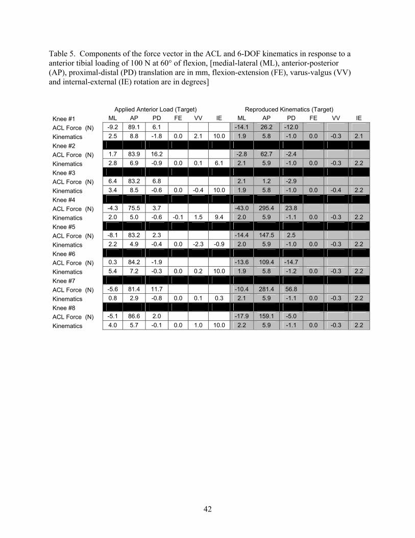
42
Table 5. Components of the force vector in the ACL and 6-DOF kinematics in response to a anterior tibial loading of 100 N at 60° of flexion, [medial-lateral (ML), anterior-posterior (AP), proximal-distal (PD) translation are in mm, flexion-extension (FE), varus-valgus (VV) and internal-external (IE) rotation are in degrees]
Applied Anterior Load (Target) Reproduced Kinematics (Target) Knee #1 ML AP PD FE VV IE ML AP PD FE VV IE ACL Force (N) -9.2 89.1 6.1 -14.1 26.2 -12.0 Kinematics 2.5 8.8 -1.8 0.0 2.1 10.0 1.9 5.8 -1.0 0.0 -0.3 2.1 Knee #2 ACL Force (N) 1.7 83.9 16.2 -2.8 62.7 -2.4 Kinematics 2.8 6.9 -0.9 0.0 0.1 6.1 2.1 5.9 -1.0 0.0 -0.3 2.2 Knee #3 ACL Force (N) 6.4 83.2 6.8 2.1 1.2 -2.9 Kinematics 3.4 8.5 -0.6 0.0 -0.4 10.0 1.9 5.8 -1.0 0.0 -0.4 2.2 Knee #4 ACL Force (N) -4.3 75.5 3.7 -43.0 295.4 23.8 Kinematics 2.0 5.0 -0.6 -0.1 1.5 9.4 2.0 5.9 -1.1 0.0 -0.3 2.2 Knee #5 ACL Force (N) -8.1 83.2 2.3 -14.4 147.5 2.5 Kinematics 2.2 4.9 -0.4 0.0 -2.3 -0.9 2.0 5.9 -1.0 0.0 -0.3 2.2 Knee #6 ACL Force (N) 0.3 84.2 -1.9 -13.6 109.4 -14.7 Kinematics 5.4 7.2 -0.3 0.0 0.2 10.0 1.9 5.8 -1.2 0.0 -0.3 2.2 Knee #7 ACL Force (N) -5.6 81.4 11.7 -10.4 281.4 56.8 Kinematics 0.8 2.9 -0.8 0.0 0.1 0.3 2.1 5.9 -1.1 0.0 -0.3 2.2 Knee #8 ACL Force (N) -5.1 86.6 2.0 -17.9 159.1 -5.0 Kinematics 4.0 5.7 -0.1 0.0 1.0 10.0 2.2 5.9 -1.1 0.0 -0.3 2.2

43
Table 6. Components of the force vector in the ACL and 6-DOF kinematics in response to a anterior tibial loading of 100 N at 90° of flexion, [medial-lateral (ML), anterior-posterior (AP), proximal-distal (PD) translation are in mm, flexion-extension (FE), varus-valgus (VV) and internal-external (IE) rotation are in degrees]
Applied Anterior Load (Target) Reproduced Kinematics (Target) Knee #1 ML AP PD FE VV IE ML AP PD FE VV IE ACL Force (N) -0.5 70.2 2.6 -1.1 17.5 11.5 Kinematics 4.8 7.8 -2.0 0.0 2.9 10.0 3.2 5.0 -0.9 0.0 0.7 3.5 Knee #2 ACL Force (N) 1.3 83.9 11.1 1.1 50.1 8.1 Kinematics 4.5 5.8 -0.5 0.0 0.1 3.6 3.6 5.2 -1.0 -0.1 0.8 3.8 Knee #3 ACL Force (N) 11.0 74.9 5.0 1.7 9.4 -8.9 Kinematics 5.3 6.6 -0.4 0.0 0.8 10.0 3.2 5.0 -0.8 -0.1 0.7 3.7 Knee #4 ACL Force (N) -2.6 72.4 -1.6 -21.2 261.9 2.0 Kinematics 2.7 3.6 0.1 -0.1 1.2 5.5 3.3 5.1 -0.8 -0.1 0.8 3.7 Knee #5 ACL Force (N) -4.6 75.2 2.2 -9.6 207.8 -5.3 Kinematics 4.2 3.6 0.5 0.0 -1.1 1.2 3.3 5.0 -0.9 -0.1 0.8 3.7 Knee #6 ACL Force (N) 6.5 75.2 3.0 -2.5 94.0 -7.6 Kinematics 6.1 6.1 0.1 0.0 2.1 10.0 3.4 5.1 -0.8 0.0 0.8 3.6 Knee #7 ACL Force (N) -7.0 76.1 10.6 10.2 254.9 23.8 Kinematics 1.2 2.8 -0.8 0.0 0.0 0.0 3.2 5.2 -0.8 -0.1 0.8 3.7 Knee #8 ACL Force (N) -3.8 79.2 -3.3 -17.4 111.9 -3.0 Kinematics 5.2 5.7 -0.4 -0.1 2.7 10.0 3.6 5.0 -0.9 -0.1 0.8 3.7

44
Table 7. Components of the force vector in the ACL and 6-DOF kinematics in response to a valgus load of 5 N m at 30° of flexion, [medial-lateral (ML), anterior-posterior (AP), proximal-distal (PD) translation are in mm, flexion-extension (FE), varus-valgus (VV) and internal-external (IE) rotation are in degrees]
Applied Anterior Load (Target) Reproduced Kinematics (Target) Knee #1 ML AP PD FE VV IE ML AP PD FE VV IE ACL Force (N) -4.3 6.6 5.0 -9.1 16.0 1.0 Kinematics 0.9 0.1 0.6 0.0 -2.3 1.0 1.2 1.2 0.6 0.0 -3.1 -0.2 Knee #2 ACL Force (N) -4.2 14.8 10.1 0.7 1.8 7.4 Kinematics 1.9 1.2 0.6 0.0 -2.6 -0.7 1.2 1.1 0.4 0.0 -3.2 0.0 Knee #3 ACL Force (N) -0.5 15.0 -2.3 -7.3 12.6 4.3 Kinematics 2.3 1.9 0.6 0.0 -2.7 1.1 0.9 1.0 0.5 0.0 -3.2 0.0 Knee #4 ACL Force (N) -12.8 28.6 4.7 -16.1 35.9 -3.5 Kinematics 0.8 0.6 0.7 0.0 -2.2 -0.6 1.2 1.2 0.6 0.0 -3.1 0.0 Knee #5 ACL Force (N) -7.6 29.2 3.8 -4.2 9.5 2.6 Kinematics 2.0 1.5 0.2 0.0 -3.4 -0.8 1.2 1.0 0.6 0.0 -3.1 0.0 Knee #6 ACL Force (N) -8.5 14.8 0.8 -13.5 1.4 0.5 Kinematics 2.7 1.8 0.5 0.0 -3.3 0.8 1.4 1.1 0.5 0.0 -3.1 0.0 Knee #7 ACL Force (N) -6.4 16.5 10.2 -13.1 67.4 13.9 Kinematics 0.9 -0.3 0.5 0.0 -2.0 -1.1 1.4 1.2 0.6 0.0 -3.2 0.0 Knee #8 ACL Force (N) -11.5 25.0 -6.9 -15.2 29.7 1.2 Kinematics 1.1 1.2 0.4 0.0 -2.5 0.4 1.3 1.2 0.5 0.0 -3.2 0.0

45
Table 8. Components of the force vector in the ACL and 6-DOF kinematics in response to a valgus load of 5 N m at 60° of flexion, [medial-lateral (ML), anterior-posterior (AP), proximal-distal (PD) translation are in mm, flexion-extension (FE), varus-valgus (VV) and internal-external (IE) rotation are in degrees] Applied Anterior Load (Target) Reproduced Kinematics (Target) Knee #1 ML AP PD FE VV IE ML AP PD FE VV IE ACL Force (N) -0.5 14.7 8.4 -2.0 3.7 2.5 Kinematics 1.2 1.0 1.3 0.0 -3.6 1.0 1.4 2.1 0.6 0.0 -4.6 -0.1 Knee #2 ACL Force (N) 0.1 14.3 0.1 0.7 1.8 7.4 Kinematics 1.6 0.8 1.0 0.0 -3.8 -0.5 1.5 2.1 0.5 0.0 -4.6 0.1 Knee #3 ACL Force (N) 1.3 4.5 -4.6 2.7 2.6 -1.3 Kinematics 2.0 3.2 0.7 0.0 -4.2 0.7 1.5 2.0 0.6 0.0 -4.7 0.1 Knee #4 ACL Force (N) -10.1 26.0 -5.1 -28.1 97.2 11.6 Kinematics 0.9 0.5 1.1 -0.1 -3.3 -0.2 1.5 2.1 0.7 0.0 -4.6 0.1 Knee #5 ACL Force (N) -0.5 19.2 5.8 -0.1 1.6 1.4 Kinematics 1.5 2.9 0.5 0.0 -4.7 -0.7 1.4 2.0 0.6 0.0 -4.6 0.1 Knee #6 ACL Force (N) -7.3 18.9 -3.2 -1.4 -6.0 -5.7 Kinematics 2.2 3.5 0.9 0.0 -5.5 0.8 1.3 2.2 0.7 0.0 -4.6 0.0 Knee #7 ACL Force (N) -6.7 19.2 2.4 -20.6 110.9 26.7 Kinematics 1.1 0.5 0.5 0.0 -3.1 -0.9 1.4 2.2 0.6 0.0 -4.6 0.1 Knee #8 ACL Force (N) -10.0 19.6 -6.3 -18.6 46.4 -7.8 Kinematics 1.3 1.3 1.1 0.1 -3.9 0.7 1.6 2.1 0.6 0.0 -4.6 0.1

46
Table 9. Components of the force vector in the ACL and 6-DOF kinematics in response to a valgus load of 5 N m at 90° of flexion, [medial-lateral (ML), anterior-posterior (AP), proximal-distal (PD) translation are in mm, flexion-extension (FE), varus-valgus (VV) and internal-external (IE) rotation are in degrees] Applied Anterior Load (Target) Reproduced Kinematics (Target) Knee #1 ML AP PD FE VV IE ML AP PD FE VV IE ACL Force (N) -0.9 18.2 1.2 -1.8 1.3 -0.8 Kinematics 2.1 1.3 2.1 0.0 -5.6 0.4 1.6 1.2 1.1 -0.1 -5.5 -0.2 Knee #2 ACL Force (N) -4.5 17.9 1.1 -1.2 1.3 5.0 Kinematics 3.5 0.4 1.7 0.0 -4.9 -0.8 2.0 1.5 1.1 -0.1 -5.4 0.1 Knee #3 ACL Force (N) 4.2 4.6 0.3 -1.5 1.3 -0.3 Kinematics 3.5 1.6 1.5 0.0 -5.7 0.7 1.6 1.1 1.1 -0.1 -5.4 0.0 Knee #4 ACL Force (N) -6.8 34.9 -3.2 -34.2 78.7 3.4 Kinematics 1.9 0.4 1.8 -0.1 -4.6 -1.0 1.8 1.3 1.0 0.0 -5.4 0.0 Knee #5 ACL Force (N) -3.0 13.4 2.6 -2.7 6.9 3.1 Kinematics 2.3 0.7 1.7 0.0 -5.2 -0.8 1.8 1.3 1.0 0.0 -5.4 0.0 Knee #6 ACL Force (N) -0.8 11.7 -10.0 0.4 3.8 -2.6 Kinematics 1.9 1.6 2.0 0.0 -6.4 0.0 1.8 1.1 1.0 0.0 -5.3 -0.1 Knee #7 ACL Force (N) -2.3 23.0 1.1 -13.9 50.8 6.5 Kinematics 1.8 0.7 0.5 0.0 -4.3 -0.1 1.8 1.3 0.9 -0.1 -5.4 0.0 Knee #8 ACL Force (N) -7.7 26.5 -12.6 -16.8 24.1 -8.6 Kinematics 2.4 1.5 1.7 0.0 -5.3 0.4 1.9 1.2 1.1 0.2 -5.4 0.0

47
6.0 DISCUSSION
This study evaluated the feasibility of estimating force in the ACL by reproducing
average kinematics in 6-DOF from one set of porcine knees onto a separate set of porcine
knees. Kinematics from a set of source cadaveric porcine knees were recorded in response to
an anterior tibial load of 100 N and a valgus load of 5 Nm at 30°, 60°, and 90° of flexion.
The same loading conditions applied to the source knees were applied to the target knees. In
addition to the applied loads, the average kinematics from the source knees was reproduced
on the target knees. To validate this methodology, the in situ forces in the ACL of the source
knees in response to applied loads were compared to the in situ forces in the ACL from
reproducing average kinematics in the target knees.
There was not a significant difference in ATT for anterior loads or valgus rotations
for valgus loads between the source and target knees for all flexion angles. In addition,
neither applied loads in the anterior, nor the valgus directions demonstrated a significant
difference in the in situ force in the ACL between the source and target knees. Reproducing
kinematics was used successfully to estimate the force in the ACL for valgus loads at 30°
and 90° of knee flexion. However, a significant difference in the in situ force in the ACL
between the source and target knees was found for all flexion angles in response to an
anterior load and at 60° of knee flexion for valgus loading. These differences can be
attributed to the variability of the coupled motions that resulted in response to the applied
loads. For example, in response to an anterior tibial load, the in situ force in the ACL of two
target knees were notably different from that obtained by reproducing the average kinematics
from the source knees, although the anterior tibial translations of both knees were identical
(Table 4). Upon further examination, the coupled internal-external rotations differed by 8°.

48
Even though forces between the source and target knees were significantly different
under anterior loads, the similarities in force between source and target knees under valgus
loading provides promising evidence that this methodology can be utilized when the source
and target knees are matched according to knee laxity. There were notable force difference
when coupled motions differed significantly indicating that all 6-DOF of knee motion are
important. When average kinematics are utilized, variations in knee laxity cause coupled
motions to be eliminated or reduced, artificially constraining the motion of the knee. An
example of this has been illustrated in Table 10 were in the last row of the table, calculation
of the average kinematics eliminated internal-external rotations. Constraining knee motion
produced high variability in the in situ force in the ACL of most knees 111, 112, this re-
emphasizes the importance of the ACL in resisting coupled motions 16, 65, 101, 113. The large
variability in ACL in situ force can be illustrated by the load displacement cures of
Figure 17. For example reproducing the ATT from the average curve (5 mm of ATT) on the
knee with the maximum toe region would result in an anterior knee force of 20 N yielding
even a smaller force in the ACL. Likewise reproducing the ATT form the average curve
onto the curve with the minimum toe region would result in an anterior knee force 2 to 3
times the applied anterior load, which would yield a very large force in the ACL as well.
Thus, coupled motions and knee laxity affect the force variability in the ACL.
Table 10. Six DOF kinematics in response to an anterior load for 4 porcine knees. [medial-lateral (ML), anterior-posterior (AP), proximal-distal (PD) translation, flexion-extension (FE), varus-valgus (VV) and internal-external (IE) rotation]
Knee ML (mm)
AP (mm)
PD (mm)
FE (°)
VV (°)
IE (°)
#1 1.5 4.6 -1.1 0.0 -0.4 -7.4#2 3.1 5.0 -0.4 0.0 -0.3 6.8 #3 1.4 5.0 -0.4 0.0 -0.6 -3.4#4 1.7 3.4 -0.3 0.0 -1.0 3.4
Avg 1.9 4.5 -0.6 0.0 -0.6 -0.1

49
Thus, one of the biggest challenges in this study was caused by variation in knee
laxity between specimens. Knee laxity is clinically defined as the length of the toe region of
the load-displacement curve. Figure 17 shows load-displacement curves from this study for
an anterior load of 100 N at 90° of flexion, and demonstrates the large variability in anterior
knee laxities. The stiffness of the average curve was very similar to the stiffness of the knees
with the minimum and maximum toe regions. Therefore, differences in the toe region of the
curve and not the stiffness of the knee appear to contribute the most to variability in knee
laxity.
Anterior knee laxity was quantified by calculating the length of the toe region of the
anterior load-displacement curve. Variability in anterior knee laxity was quantified as the
range of anterior laxity divided by the average anterior laxity for the eight source and target
knees times 100. The average lengths of the toe region for source and target knees (n = 16)
were 2.0 mm, 3.8 mm, and 3.3 mm at 30°, 60°, and 90° of flexion, respectively. The length
of the toe region for all source and target knees ranged from 0.6 to 4.3 mm, 1.3 to 7.0 mm,
and 1.5 to 6.3 mm at 30°, 60°, and 90° of flexion, respectively. Anterior knee laxity showed
variability of 183%, 153%, and 146% at these same flexion angles, respectively.

50
Figure 17. Load-displacement curve in response to an applied load of 100 N at 90°of flexion – The standard deviation of the toe region is represented on the average curve
Multiple measures of knee laxity should to be performed throughout the range of
knee flexion-extension because of the nonlinear behavior of the load-displacement curve in
biological specimens. For example, the lengths of the toe region in one knee tested were 3.3,
3.0, and 2.5 mm, while another knee had toe region lengths of 3.3, 7.1, and 6.5 mm at 30°,
60°, and 90° of knee flexion. In this study, knee kinematics with similar anterior knee laxity
had similar coupled internal-external rotations. Two knees with anterior knee laxity which
differed by only 0.0, 0.2, and 1.1 mm at 30°, 60°, and 90° of flexion showed differences in
coupled internal-external rotation of 4.6°, 1.2°, and 1.2° at these same flexion angles,
respectively. Two knees with anterior laxity which varied by 3.3, 3.6, and 2.7 mm at 30°,
60°, and 90° of knee flexion showed differences in coupled internal-external rotation of
11.2°, 9.8° and 10.0°at these same flexion angles, respectively.
#1 (Max Toe Region)Average Curve, n = 8
#2 (Min Toe Region)
Anterior Tibial Translation (mm)
Ant
erio
r Kne
e Lo
ad (N
)
20
40
60
80
100
1.0 2.0 3.0 4.0 5.0 6.0 7.0 8.0
51
Knee laxity can be quantified in all 6-DOF, but several of these degrees of freedom
are either suppressed or coupled because of the constraints provided by the ligamentous and
bony structures. For example, axial rotations of the tibia causes coupled anterior-posterior
translations and varus-valgus rotations 114, 115. Most medial-lateral translations of the knee
are coupled with rotations of the knee, and are affected by the bony geometry of the tibia and
femur116. Consequently, medial-lateral translations are a poor predictor of knee laxity.
Proximal-distal translations do not pose a problem when reproducing average kinematics,
since the average kinematics are applied to the knee specific reference positions. Anterior
tibial translation has been shown to be a good indicator of knee laxity in this study and in
many previous studies117-122. Anterior knee laxity (length of the toe region of the load-
displacement curve) was not only variable for the porcine model in this study, but has also
been reported to vary in cadaveric human knees by as much as 200%, 116%, 89%, and 84%
at 0°, 30°, 60°, and 90° of knee flexion, respectively, in response to an anterior load of 225 N 122.
In addition to translational laxity of the knee, rotational laxity must also be
considered. Varus-valgus rotations have been shown to be very repeatable between subjects
in previous studies120, 123. Therefore, varus valgus rotations are a poor predictor of knee
laxity. A constant 3 Nm internal and external rotational load throughout knee flexion-
extension has been shown to result in differences in internal-external laxity in human cadaver
knees of up to 200% 123 (Figure 18). Furthermore, this type of test for knee laxity has been
shown to be consistent and reproducible within the same cadaveric knee specimens 123.
Hence, anterior translation and internal-external rotations are the most useful knee motions
for determining laxity. The average kinematics from subjects with similar anterior and
internal-external knee laxity throughout the range of passive flexion-extension could be
grouped, and later matched to a comparable cadaveric specimen.
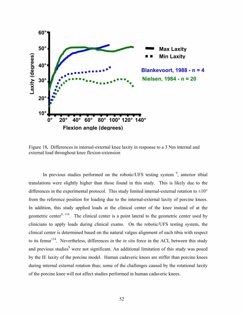
52
Figure 18. Differences in internal-external knee laxity in response to a 3 Nm internal and external load throughout knee flexion-extension
In previous studies performed on the robotic/UFS testing system 9, anterior tibial
translations were slightly higher than those found in this study. This is likely due to the
differences in the experimental protocol. This study limited internal-external rotation to ±10°
from the reference position for loading due to the internal-external laxity of porcine knees.
In addition, this study applied loads at the clinical center of the knee instead of at the
geometric center9, 114. The clinical center is a point lateral to the geometric center used by
clinicians to apply loads during clinical exams. On the robotic/UFS testing system, the
clinical center is determined based on the natural valgus alignment of each tibia with respect
to its femur114. Nevertheless, differences in the in situ force in the ACL between this study
and previous studies9 were not significant. An additional limitation of this study was posed
by the IE laxity of the porcine model. Human cadaveric knees are stiffer than porcine knees
during internal external rotation thus; some of the challenges caused by the rotational laxity
of the porcine knee will not affect studies performed in human cadaveric knees.
140°120°100°80°60° 40° 20° 0° 10°
20°
40°
30°
50°
60°
Flexion angle (degrees)
Laxi
ty (d
egre
es)
Blankevoort, 1988 - n = 4Nielsen, 1984 - n = 20
Max Laxity Min Laxity

53
One of the reasons why porcine knees are very lax is due to the absence of the iliotibial band,
which plays a major role in maintaining rotatory stability in vivo.
Experimental data utilizing averaged kinematics will be valuable for advancing the
understanding of ACL forces during in vivo activities. Evaluating the forces of different
ACL reconstructions during in vivo activities will allow graft function to be compared under
clinically relevant loading conditions. Results from this research will also elucidate the
forces in the ACL during various rehabilitation exercises. This will allow rehabilitation
protocols to be optimized, avoiding excessive forces in the ACL that could damage the
healing graft. However, average kinematics must account for coupled motions and knee
laxity by grouping knees with similar laxity.
54
7.0 FUTURE DIRECTIONS
Two extension of the proposed methodology of reproducing average kinematics will
be presented. Method 1 would extend the current methodology by accounting for knee laxity
in multiple degrees of freedom by grouping sets of knees with similar laxity. Method 2
would account for differences in knee laxity by using the end of the toe region of the load
displacement curve as a reference instead of the passive path of flexion extension. Method 1
will require clinicians to apply internal, external, and anterior loads though out the range of
flexion extension until a firm stopping point is felt. This will provide the translational and
rotational laxity of each subject tested. Load displacement curves for internal, external, and
anterior loads would be compared between subjects. Subjects with similar correlation
coefficient for both anterior and internal-external laxity would be grouped and the average
kinematics calculated. Once a database of subject kinematics has been established, cadaveric
knee specimens would be tested in a similar manner to human subjects. An anterior load of
100 N, and an internal, and an external load of 3 Nm would be applied to the cadaveric knee
at several flexion angles throughout the range of flexion-extension. Next, the set of average
subject kinematics that correlates best to the knee laxity of the cadaveric knee would be
reproduced.
Method 2 would require clinicians to apply anterior loads though out the range of
flexion extension until a firm stopping point is felt. Recorded subject kinematics would use
the end of the toe region instead of the passive as a reference. A 100 N anterior load would
also be applied with the robotic/UFS testing system to the cadaveric knee to establish a
reference position from which the recorded subject kinematics could be added. Method 1
should also account for coupled motions in some way; this could be accomplished by
grouping knees with similar laxities as in Method 1.

55
In spite of the challenges posed by this research project, several alternative solutions
were established. This study provides promising evidence that this innovative methodology
can be extended to account for knee laxity and coupled motions. Thus, an accurate
understanding of the forces in the ACL and ACL graft during in vivo activities may be
obtained using an extension of this methodology.

56
BIBLIOGRAPHY 1. Miyasaka, K., et al., The incidence of knee ligament injuries in the general
population. American Journal of Knee Surgery, 1991. 4(1): p. 3-8.
2. Deibert, M.C., et al., Skiing injuries in children, adolescents, and adults. Journal of Bone & Joint Surgery - American Volume, 1998. 80(1): p. 25-32.
3. Griffin, L.Y., et al., Noncontact anterior cruciate ligament injuries: Risk factors and prevention strategies. Journal of the American Academy of Orthopeadic Surgeons, 2000. 8(3): p. 141-50.
4. Woo, S.L., et al., The effectiveness of reconstruction of the anterior cruciate ligament with hamstrings and patellar tendon . A cadaveric study comparing anterior tibial and rotational loads. J Bone Joint Surg Am, 2002. 84-A(6): p. 907-14.
5. Fleming, B.C., et al., The effect of weightbearing and external loading on anterior cruciate ligament strain. J Biomech, 2001. 34(2): p. 163-70.
6. Mikkelsen, C., S. Werner, and E. Eriksson, Closed kinetic chain alone compared to combined open and closed kinetic chain exercises for quadriceps strengthening after anterior cruciate ligament reconstruction with respect to return to sports: a prospective matched follow-up study. Knee Surgery, Sports Traumatology, Arthroscopy, 2000. 8(6): p. 337-42.
7. Kanamori, A., et al., The forces in the anterior cruciate ligament and knee kinematics during a simulated pivot shift test: A human cadaveric study using robotic technology. Arthroscopy, 2000. 16(6): p. 633-9.
8. Jomha, N.M., et al., Arthroscopic reconstruction of the anterior cruciate ligament with patellar-tendon autograft and interference screw fixation. The results at seven years. Journal of Bone & Joint Surgery - British Volume, 1999. 81(5): p. 775-9.
9. Li, G., et al., Effect of combined axial compressive and anterior tibial loads on in situ forces in the anterior cruciate ligament: a porcine study. Journal of Orthopaedic Research, 1998. 16(1): p. 122-7.
10. Bach, B.R., Jr., et al., Arthroscopically assisted anterior cruciate ligament reconstruction using patellar tendon autograft. Five to nine-year follow-up evaluation. Am J Sports Med, 1998. 26(1): p. 20-9.
57
11. Aglietti, P., et al., Long-term study of anterior cruciate ligament reconstruction for chronic instability using the central one-third patellar tendon and a lateral extraarticular tenodesis. American Journal of Sports Medicine, 1992. 20(1): p. 38-45.
12. Miyasaka, K.C., et al., The incidence of knee ligament injuries in the general population. Am J Knee Surg, 1991. 4: p. 3-8.
13. Kaplan, N., T.L. Wickiewicz, and R.F. Warren, Primary surgical treatment of anterior cruciate ligament ruptures. A long-term follow-up study. American Journal of Sports Medicine, 1990. 18(4): p. 354-8.
14. Sakane, M., et al., In situ forces in the anterior cruciate ligament and its bundles in response to anterior tibial loads. J Orthop Res, 1997. 15(2): p. 285-93.
15. Wong, E.K., In-Situ Forces in the Bundles of the Anterior Cruciate Ligament: An Experimental and Computational Approach, in Bioengineering. 2000, University of Pittsburgh: Pittsburgh. p. 1-77.
16. Kanamori, A., et al., The forces in the anterior cruciate ligament and knee kinematics during a simulated pivot shift test: A human cadaveric study using robotic technology. Arthroscopy, 2000. 16(6): p. 633-9.
17. Sakane, M., et al., In situ forces in the anterior cruciate ligament and its bundles in response to anterior tibial loads. Journal of Orthopaedic Research, 1997. 15(2): p. 285-93.
18. Loh, J.C., et al., Knee stability and graft function following anterior cruciate ligament reconstruction: Comparison between 11 o'clock and 10 o'clock femoral tunnel placement. Arthroscopy, 2003. 19(3): p. 297-304.
19. Lewis, J.L., et al., Method for establishing and measuring in vivo forces in an anterior cruciate ligament composite graft: response to differing levels of load sharing in a goat model. Journal of Orthopaedic Research, 1994. 12(6): p. 780-8.
20. Lundberg, W.R., et al., In vivo forces during remodeling of a two-segment anterior cruciate ligament graft in a goat model. Journal of Orthopaedic Research, 1997. 15(5): p. 645-51.
21. Holden, J.P., et al., In vivo forces in the anterior cruciate ligament: Direct measurements during walking and trotting in a quadruped. Journal of Biomechanics, 1994. 27(5): p. 517-26.
22. Beynnon, B.D., et al., The strain behavior of the anterior cruciate ligament during squatting and active flexion-extension. A comparison of an open and a closed kinetic chain exercise. American Journal of Sports Medicine, 1997. 25(6): p. 823-9.
23. Toutoungi, D.E., et al., Cruciate ligament forces in the human knee during rehabilitation exercises. Clin Biomech (Bristol, Avon), 2000. 15(3): p. 176-87.

58
24. Zheng, N., et al., An analytical model of the knee for estimation of internal forces during exercise. J Biomech, 1998. 31(10): p. 963-7.
25. Fleming, B.C., et al., The strain behavior of the anterior cruciate ligament during stair climbing: an in vivo study. Arthroscopy, 1999. 15(2): p. 185-91.
26. Morrison, J.B., The mechanics of the knee joint in relation to normal walking. J Biomech, 1970. 3(1): p. 51-61.
27. Ahmed, A.M. and C. McLean, In vitro measurement of the restraining role of the anterior cruciate ligament during walking and stair ascent. J Biomech Eng, 2002. 124(6): p. 768-79.
28. Escamilla, R.F., et al., Biomechanics of the knee during closed kinetic chain and open kinetic chain exercises. Med Sci Sports Exerc, 1998. 30(4): p. 556-69.
29. Agur, A.M.R., Lee, M. J. and Grant, J. C. B., . Atlas of Anatomy (10th; Philadelphia: Lippincott Williams & Wilkins, 1999). Grant's Atlas of Anatomy, ed. 10th. 1999: Philadelphia: Lippincott Williams & Wilkins.
30. Harner, C.D., et al., Comparative study of the size and shape of human anterior and posterior cruciate ligaments. J Orthop Res, 1995. 13(3): p. 429-34.
31. Harner, C.D., et al. Biomechanical analysis of a double bundle posterior cruciate ligament reconstruction: Comparison with a single bundle reconstrution. in Meeting of the American Orthopaedic Society for Sports medicine. 1999. Traverse City, MI.
32. Frank, C.B., Ligament Healing: Current Knowledge and Clinical Applications. J Am Acad Orthop Surg, 1996. 4(1): p. 74-83.
33. Rosenberg, T.D. and G.L. Rasmussen, The function of the anterior cruciate ligament during anterior drawer and Lachman's testing. An in vivo analysis in normal knees. Am J Sports Med, 1984. 12(4): p. 318-22.
34. Sydney, S.V., D.W. Haynes, and D.S. Hungerford, The kinematics of the pivot shift. Transactions of the orthopaedic Research Society, 1987. 12: p. 199.
35. Bach, B.R., Jr., et al., Single-incision endoscopic anterior cruciate ligament reconstruction using patellar tendon autograft. Minimum two-year follow-up evaluation. Am J Sports Med, 1998. 26(1): p. 30-40.
36. Harter, R.A., L.R. Osternig, and K.M. Singer, Instrumented Lachman tests for the evaluation of anterior laxity after reconstruction of the anterior cruciate ligament. J Bone Joint Surg Am, 1989. 71(7): p. 975-83.
37. Noyes, F.R., et al., The diagnosis of knee motion limits, subluxations, and ligament injury. American Journal of Sports Medicine, 1991. 19(2): p. 163-71.

59
38. Wong, E.K., et al., The Force Distribution in the Bundles of the ACL during Simulated Joint Motions: A Computational Approach. Journal of Biomechanical Engineering, 2001 (Submitted).
39. Li, G., et al., Effect of comined axial compressive and anterior tibial loads on in situ forces in the anterior cruciate ligament: A porcine study. J Orthop Res, 1998. 16: p. 122-127.
40. Kannus, P. and M. Jarvinen, Conservatively treated tears of the anterior cruciate ligament. Long-term results. J Bone Joint Surg Am, 1987. 69(7): p. 1007-12.
41. Noyes, F.R., et al., The symptomatic anterior cruciate-deficient knee. Part I: The long-term functional disability in athletically active individuals. J Bone Joint Surg Am, 1983. 65(2): p. 154-62.
42. Aglietti, P., et al., Arthroscopic-assisted anterior cruciate ligament reconstruction with the central third patellar tendon. A 5-8-year follow-up. Knee Surg Sports Traumatol Arthrosc, 1997. 5(3): p. 138-44.
43. Colombet, P., et al., Anterior cruciate ligament reconstruction using four-strand semitendinosus and gracilis tendon grafts and metal interference screw fixation. Arthroscopy, 2002. 18(3): p. 232-7.
44. Aune, A.K., et al., Four-strand hamstring tendon autograft compared with patellar tendon-bone autograft for anterior cruciate ligament reconstruction. A randomized study with two-year follow-up. Am J Sports Med, 2001. 29(6): p. 722-8.
45. Anderson, A.F., R.B. Snyder, and A.B. Lipscomb, Jr., Anterior cruciate ligament reconstruction. A prospective randomized study of three surgical methods. Am J Sports Med, 2001. 29(3): p. 272-9.
46. Bach, B.R., Jr., et al., Arthroscopically assisted anterior cruciate ligament reconstruction using patellar tendon autograft. Five- to nine-year follow-up evaluation. Am J Sports Med, 1998. 26(1): p. 20-9.
47. Ritchie, J.R. and R.D. Parker, Graft selection in anterior cruciate ligament revision surgery. Clin Orthop, 1996(325): p. 65-77.
48. Clancy, W.G., Jr., et al., Anterior cruciate ligament reconstruction using one-third of the patellar ligament, augmented by extra-articular tendon transfers. Journal of Bone & Joint Surgery - American Volume, 1982. 64(3): p. 352-9.
49. Allen, C.R., et al., Importance of the medial meniscus in the anterior cruciate ligament- deficient knee. J Orthop Res, 2000. 18(1): p. 109-15.
50. Rosenberg, T.D. and K.T. Deffner, ACL reconstruction: semitendinosus tendon is the graft of choice. Orthopedics, 1997. 20(5): p. 396-398.
60
51. Specchiulli, F., et al., Anterior cruciate ligament reconstruction. A comparison of 2 techniques. Clinical Orthopaedics & Related Research, 1995(311): p. 142-7.
52. Rowden, N.J., et al., Anterior cruciate ligament graft fixation. Initial comparison of patellar tendon and semitendinosus autografts in young fresh cadavers. American Journal of Sports Medicine, 1997. 25(4): p. 472-8.
53. Otero, A.L. and L. Hutcheson, A comparison of the doubled semitendinosus/gracilis and central third of the patellar tendon autografts in arthroscopic anterior cruciate ligament reconstruction. Arthroscopy, 1993. 9(2): p. 143-8.
54. Corry, I.S., et al., Arthroscopic reconstruction of the anterior cruciate ligament. A comparison of patellar tendon autograft and four-strand hamstring tendon autograft. Am J Sports Med, 1999. 27(4): p. 444-54.
55. Steiner, M.E., et al., Anterior cruciate ligament graft fixation. Comparison of hamstring and patellar tendon grafts. American Journal of Sports Medicine, 1994. 22(2): p. 240-7.
56. Rupp, S., et al., Ligament graft initial fixation strength using biodegradable interference screws. Journal of Biomedical Materials Research, 1999. 48(1): p. 70-4.
57. Caborn, D., et al., Biomechanical comparison between BioScrew and titanium alloy interference screws for bone-patellar tendon-bone graft fixation in anterior cruciate ligament reconstruction. Arthroscopy, 1997. 13(2): p. 229-232.
58. Kurosaka, M., S. Yoshiya, and J.T. Andrish, A biomechanical comparison of different surgical techniques of graft fixation in anterior cruciate ligament reconstruction. American Journal of Sports Medicine, 1987. 15(3): p. 225-9.
59. Seil, R., et al., Comparison of initial fixation strength between biodegradable and metallic interference screws and a press-fit fixation technique in a porcine model. American Journal of Sports Medicine, 1998. 26(6): p. 815-9.
60. Kousa, P., et al., The fixation strength of six hamstring tendon graft fixation devices in anterior cruciate ligament reconstruction. Part II: tibial site. Am J Sports Med, 2003. 31(2): p. 182-8.
61. Kousa, P., et al., The fixation strength of six hamstring tendon graft fixation devices in anterior cruciate ligament reconstruction. Part I: femoral site. Am J Sports Med, 2003. 31(2): p. 174-81.
62. Fu, F.H., et al., Current trends in anterior cruciate ligament reconstruction. Part II. Operative procedures and clinical correlations. American Journal of Sports Medicine, 2000. 28(1): p. 124-30.
63. Van Scyoc, A.H., Plakseychuk, A., Musahl, V., Sasaki, T., Castner,C.J., Debski, R.E., McMahon, P.J., Fu. F.H., Woo, S.L-Y. FEMORAL TUNNEL POSITION AFFECTS

61
ACL GRAFT FUNCTION: A CADAVERIC STUDY USING TWO ROBOTS. in The American Orthopaedic Society for Sports Medicine. 2003. San Diego, California.
64. Loh, J.C., et al., Knee stability and graft function following anterior cruciate ligament reconstruction: comparison between 11 o'clock and 10 o'clock femoral tunnel placement. Arthroscopy, 2002. Accepted.
65. Yagi, M., et al., Biomechanical analysis of an anatomic anterior cruciate ligament reconstruction. Am J Sports Med, 2002. 30(5): p. 660-6.
66. Scheffler, S.U., et al., Structure and function of the healing medial collateral ligament in a goat model. Ann Biomed Eng, 2001. 29(2): p. 173-80.
67. Yamamoto, Y., Hsu, W.H., Van Scyoc, A.H., Takakura, Y., Debski, R.E., Woo, S.L-Y. DOES A 10 O'CLOCK SINGLE-BUNDLE ACL RECONSTRUCTION RESTORE NORMAL KNEE KINEMATICS AND IN SITU FORCES AS CLOSELY AS AN ANATOMIC DOUBLE-BUNDLE ACL RECONSTRUCTION. in Orthopaedic Research Society. 2004. San Francisco, CA.
68. Papageorgiou, C.D., et al., The biomechanical interdependence between the ACL replacement graft and the medial meniscus. American Journal of Sports Medicine, 2001 (In-press).
69. Yasuhiko Watanabe MD, et al. Does Partial Meniscectomy Affect Knee Instability? in Orthopaedic Research Society. 2002. Dallas Texas.
70. Muller, W., et al., Evaluation du genou selon I'OAK: Une nouvelle maniere permettant de documenter les lesions ligamentaires du genou, in Le genou Anatomie, biomecaniqu et reconstruction ligamentaire, W. Muller, Editor. 1994, Springer-Verlag: Berlin Heidelberg. p. 329-335.
71. Feagin, J.A., Jr., et al., Anterior cruciate ligament reconstruction. Bone-patella tendon-bone versus semitendinosus anatomic reconstruction. Clinical Orthopaedics & Related Research, 1997(341): p. 69-72.
72. Mott, H.W., Semitendinosus anatomic reconstruction for cruciate ligament insufficiency. Clinical Orthopaedics & Related Research, 1983(172): p. 90-2.
73. Muneta, T., et al., Two-bundle reconstruction of the anterior cruciate ligament using semitendinosus tendon with endobuttons: operative technique and preliminary results. Arthroscopy, 1999. 15(6): p. 618-24.
74. Hara, K., et al., Reconstruction of the anterior cruciate ligament using a double bundle. Arthroscopy, 2000. 16(8): p. 860-4.
75. Pederzini, L., et al., Technical note: double tibial tunnel using quadriceps tendon in anterior cruciate ligament reconstruction. Arthroscopy, 2000. 16(5): p. E9.

62
76. Radford, W.J. and A.A. Amis, Biomechanics of a double prosthetic ligament in the anterior cruciate deficient knee. Journal of Bone & Joint Surgery - British Volume, 1990. 72(6): p. 1038-43.
77. Beynnon, B.D., et al., Anterior cruciate ligament strain behavior during rehabilitation exercises in vivo. American Journal of Sports Medicine, 1995. 23(1): p. 24-34.
78. Erikkson, E., Sports injuries of the knee ligaments-their diagnosis treatment and rehabilitation. Medical Science in Sports, 1976. 8: p. 133-144.
79. Andriacchi, T.P. and D. Birac, Functional testing in the anterior cruciate ligament-deficient knee. Clinical Orthopaedics & Related Research, 1993(288): p. 40-7.
80. Shelbourne, K.D., T.E. Klootwyk, and M.S. DeCarlo, Update on accelerated rehabilitation after anterior cruciated ligament reconstruction. Journal of Orthopaedic Sports and Physical Therapy, 1992(15): p. 303-08.
81. Lutz, G.E., et al., Comparison of tibiofemoral joint forces during open-kinetic-chain and closed-kinetic-chain exercises. Journal of Bone & Joint Surgery - American Volume, 1993. 75(5): p. 732-9.
82. Jonsson, H. and J. Karrholm, Three-dimensional knee joint movements during a step-up: Evaluation after anterior cruciate ligament rupture. Journal of Orthopaedic Research, 1994. 12(6): p. 769-79.
83. Jonsson, H., J. Karrholm, and L.G. Elmqvist, Kinematics of active knee extension after tear of the anterior cruciate ligament. American Journal of Sports Medicine, 1989. 17(6): p. 796-802.
84. Beynnon, B.D. and A.A. Amis, In vitro testing protocols for the cruciate ligaments and ligament reconstructions. Knee Surgery, Sports Traumatology, Arthroscopy, 1998. 6 Suppl 1: p. S70-6.
85. Beynnon, B.D. and R.J. Johnson, Anterior cruciate ligament injury rehabilitation in athletes. Biomechanical considerations. Sports Medicine, 1996. 22(1): p. 54-64.
86. Shoemaker, S.C., et al., Quadriceps/anterior cruciate graft interaction. An in vitro study of joint kinematics and anterior cruciate ligament graft tension. Clinical Orthopaedics & Related Research, 1993(294): p. 379-90.
87. Li, G., et al., A validated three-dimensional computational model of a human knee joint. Journal of Biomechanical Engineering, 1999. 121(6): p. 657-62.
88. Frndak, P.A. and C.C. Berasi, Rehabilitation concerns following anterior cruciate ligament reconstruction. Sports Medicine, 1991. 12(5): p. 338-46.
63
89. Howell, S.M., Anterior tibial translation during a maximum quadriceps contraction: Is it clinically significant? American Journal of Sports Medicine, 1990. 18(6): p. 573-8.
90. Irrgang, J.J., Modern trends in anterior cruciate ligament rehabilitation: nonoperative and postoperative management. Clinics in Sports Medicine, 1993. 12(4): p. 797-813.
91. Zacharias, I., M.L. Hull, and S.M. Howell, Static and fatigue strength of a fixation device transducer for measuring anterior cruciate ligament graft tension. J Biomech Eng, 2000. 122(6): p. 600-3.
92. Zacharias, I., et al., In vivo calibration of a femoral fixation device transducer for measuring anterior cruciate ligament graft tension: a study in an ovine model. J Biomech Eng, 2001. 123(4): p. 355-61.
93. Shelburne, K.B. and M.G. Pandy, Determinants of cruciate-ligament loading during rehabilitation exercise. Clin Biomech (Bristol, Avon), 1998. 13(6): p. 403-413.
94. Lew, W.D. and J.L. Lewis, A technique for calculating in vivo ligament lengths with application to the human knee joint. J Biomech, 1978. 11(8-9): p. 365-77.
95. Fujie, H., et al., Forces and moments in six-DOF at the human knee joint: mathematical description for control. J Biomech, 1996. 29(12): p. 1577-85.
96. Fujie, H., et al., The use of robotics technology to study human joint kinematics: a new methodology. J Biomech Eng, 1993. 115(3): p. 211-7.
97. Rudy, T.W., et al., A combined robotic/universal force sensor approach to determine in situ forces of knee ligaments. J Biomech, 1996. 29(10): p. 1357-60.
98. Fujie, H., et al., The use of a universal force-moment sensor to determine in-situ forces in ligaments: a new methodology. J Biomech Eng, 1995. 117(1): p. 1-7.
99. Xerogeanes, J.W., et al., Effect of knee flexion on the in situ force distribution in the human anterior cruciate ligament. Knee Surgery, Sports Traumatology, Arthroscopy, 1995. 3(1): p. 9-13.
100. Ishibashi, Y., et al., The effect of anterior cruciate ligament graft fixation site at the tibia on knee stability: evaluation using a robotic testing system. Arthroscopy, 1997. 13(2): p. 177-82.
101. Kanamori, A., et al., The effects of axial tibial torque on the function of the anterior cruciate ligament: A biomechanical study of a simulated pivot shift test. Arthroscopy, 2001 (Revised).
102. Livesay, G.A., et al., Evaluation of the effect of joint constraints on the in situ force distribution in the anterior cruciate ligament. J Orthop Res, 1997. 15(2): p. 278-84.
64
103. Hoher, J., et al., The position of the tibia during graft fixation affects knee kinematics and graft forces for anterior cruciate ligament reconstruction. Am J Sports Med, 2001. 29(6): p. 771-6.
104. Takai, S., et al., Determination of the in situ loads on the human anterior cruciate ligament. J Orthop Res, 1993. 11(5): p. 686-95.
105. Grood, E.S. and W.J. Suntay, A joint coordinate system for the clinical description of three- dimensional motions: application to the knee. Journal of Biomechanical Engineering, 1983. 105(2): p. 136-44.
106. Cho, K.O., Reconstruction of the anterior cruciate ligament by semitendinosus tenodesis. Journal of Bone & Joint Surgery - American Volume, 1975. 57(5): p. 608-12.
107. Craig, J.J., Introduction to Robotics, 2nd edn. 1989, New York: Addison-Wesley Publishing Company.
108. Song, Y., et al. EFFECT OF THE BIOLOGICAL VARIATION BETWEEN KNEES ON THE FORCE IN THE ANTERIOR CRUCIATE LIGAMENT. in ISLT3. 2002.
109. Ma, C.B., et al., Significance of changes in the reference position for measurements of tibial translation and diagnosis of cruciate ligament deficiency. J Orthop Res, 2000. 18(2): p. 176-82.
110. Xerogeanes, J.W., et al., A functional comparison of animal anterior cruciate ligament models to the human anterior cruciate ligament. Ann Biomed Eng, 1998. 26(3): p. 345-52.
111. Rudy, T.W., et al., A combined robotic/universal force sensor approach to determine in situ forces of knee ligaments. Journal of Biomechanics, 1996. 29(10): p. 1357-60.
112. Andriacchi, T.P., et al., Model studies of the stiffness characteristics of the human knee joint. J Biomech, 1983. 16(1): p. 23-9.
113. Loh, J.C. Does Femoral Tunnel Position Improve Knee Stability in ACL Reconstruction. in ORS. 2001. Dallas, Texas.
114. Rudy, T.W., et al., The effect of the point of application of anterior tibial loads on human knee kinematics. J Biomech, 2000. 33(9): p. 1147-52.
115. Inoue, M., et al., Treatment of the medial collateral ligament injury. I: The importance of anterior cruciate ligament on the varus-valgus knee laxity. Am J Sports Med, 1987. 15(1): p. 15-21.
116. Wilson, D.R., J.D. Feikes, and J.J. O'Connor, Ligaments and articular contact guide passive knee flexion. J Biomech, 1998. 31(12): p. 1127-36.

65
117. Katz, J.W. and R.J. Fingeroth, The diagnostic accuracy of ruptures of the anterior cruciate ligament comparing the Lachman test, the anterior drawer sign, and the pivot shift test in acute and chronic knee injuries. Am J Sports Med, 1986. 14(1): p. 88-91.
118. Kim, S.J. and H.K. Kim, Reliability of the anterior drawer test, the pivot shift test, and the Lachman test. Clin Orthop, 1995(317): p. 237-42.
119. Zhai, G.H., [Diagnosis of anterior cruciate ligament injury of the knee joint]. Zhonghua Wai Ke Za Zhi, 1992. 30(1): p. 10-3, 61.
120. Markolf, K.L., J.S. Mensch, and H.C. Amstutz, Stiffness and laxity of the knee--the contributions of the supporting structures. A quantitative in vitro study. J Bone Joint Surg Am, 1976. 58(5): p. 583-94.
121. Piziali, R.L., et al., The contribution of the cruciate ligaments to the load-displacement characteristics of the human knee joint. J Biomech Eng, 1980. 102(4): p. 277-83.
122. Eagar, P., M.L. Hull, and S.M. Howell, A method for quantifying the anterior load-displacement behavior of the human knee in both the low and high stiffness regions. J Biomech, 2001. 34(12): p. 1655-60.
123. Blankevoort, L., R. Huiskes, and A. de Lange, The envelope of passive knee joint motion. J Biomech, 1988. 21(9): p. 705-20.


![Winners List - Motor Car [ACL] (motor car).pdfareej 14 Motor Car ACL 016 2,000 15,000 ACL-35202****9025-016 Shamaila Shafique 15 Motor Car ACL 017 2,000 10,100 ACL-35202****4553-017](https://static.fdocuments.us/doc/165x107/60e41d8b31ed9359ad784c32/winners-list-motor-car-acl-motor-carpdf-areej-14-motor-car-acl-016-2000.jpg)