Essential Safety Precautions WARNINGS - · PDF filetoto AGPAGP correct Incorrect toto AGPAGP...
8
-1- RS-232C/485 Isolation Unit Installation Guide Thank you for purchasing Pro-face's RS-232C/485 Isolation Unit (CA3-ISO232-01/ CA3-ISO485-01). This unit is designed to utilize Pro-face product,Display(Unit) serial interface connector (D-sub9-pin), and electrically separates the serial interface signal from the Display's chassis. For the details of the applicable models, please refer to each Display’s Hardware Manual or Pro-face Home Page. URL http://www.pro-face.com/ • To avoid an electric shock, prior to connecting this unit to the Display's serial interface, confirm that the Display's power supply is completely turned OFF, via a breaker, or similar unit. • Do not modify this unit. Doing so may cause a fire or an electric shock. • Do not use this unit in an environment where flammable gases are present, since operating this unit may cause an explosion. • When disposing of this product, be sure to do so according to your country’s standards for industrial waste disposal. General Safety Precautions • Do not allow water, liquids, metal or charged particles to enter inside this unit, since they can cause either a unit malfunction or an electrical shock. • Do not use or store this unit in direct sunlight, in excessively dusty or dirty environments or where excessive vibration can occur. • Do not store or use this unit where strong jolting can occur. • Do not store or use this unit where chemicals (such as organic solvents, etc.) and acids can evaporate, or where chemicals and acids are present in the air. WARNINGS Essential Safety Precautions
Transcript of Essential Safety Precautions WARNINGS - · PDF filetoto AGPAGP correct Incorrect toto AGPAGP...

-1-
RS-232C/485 Isolation UnitInstallation Guide
Thank you for purchasing Pro-face's RS-232C/485 Isolation Unit (CA3-ISO232-01/CA3-ISO485-01). This unit is designed to utilize Pro-face product,Display(Unit) serialinterface connector (D-sub9-pin), and electrically separates the serial interface signalfrom the Display's chassis.For the details of the applicable models, please refer to each Display’s HardwareManual or Pro-face Home Page.
URL http://www.pro-face.com/
• To avoid an electric shock, prior to connecting this unit to theDisplay's serial interface, confirm that the Display's power supply iscompletely turned OFF, via a breaker, or similar unit.
• Do not modify this unit. Doing so may cause a fire or an electric shock.• Do not use this unit in an environment where flammable gases are
present, since operating this unit may cause an explosion.• When disposing of this product, be sure to do so according to your
country’s standards for industrial waste disposal.
General Safety Precautions• Do not allow water, liquids, metal or charged particles to enter inside this unit,
since they can cause either a unit malfunction or an electrical shock.• Do not use or store this unit in direct sunlight, in excessively dusty or dirty
environments or where excessive vibration can occur.• Do not store or use this unit where strong jolting can occur.• Do not store or use this unit where chemicals (such as organic solvents, etc.)
and acids can evaporate, or where chemicals and acids are present in the air.
WARNINGSEssential Safety Precautions

-2-
1 External Drawings and DimensionsUnit mm:[in.]
The CA3-ISO232-01 and CA3-ISO485-01 are a CE marked, EMC compliant products.These units conform to EN55011 Class A and EN61000-6-2 directives.
CE Marking
Please check that the following items are included in your package.Isolation Unit
RS-232C Isolation Unit ....... CA3-ISO232-01
RS-485 Isolation Unit .......... CA3-ISO485-01
Installation Guide (this guide)Attachment Screws (2)
Package Contents
110[4.33]
40[1
.57]
27[1.06]
PLC Display
totoAG
PA
GP
420[16.54] 48[1.89]
totoAG
PA
GP 31
[1.2
2]B
A
RS-232C Isolation Unit RS-485 Isolation Unit
CommunicationMethod
RS-232C RS-485
Interface D-Sub 9-pin socket D-Sub 9-pin plug
CommunicationMethod
RS-232C / RS-422(Via DIP switch)
RS-485 / RS-422(Via DIP switch)
Interface D-Sub 9-pin plug D-Sub 9-pin socket
Input(DisplaySide)
Output(PLC Side)
A
B

-3-
2 Specifications
Item DescriptionCooling Method Natural air circulation
Weight 170g[0.4lb] or lessExternal Dimensions W110mm[4.33in]xH40mm[1.57in]xD27mm[1.06in]
Item DescriptionRated Voltage DC5V(supplied from the Display)
Power Consumption 1.25W or lessVoltage Endurance AC1000V 20mA 1min(When attached to the Display)
Insulation Resistance DC500V 10MΩ or higher(When attached to the Display)
.2.1 Electrical
.2.2 Environmental
.2.3 Structural
Item Description
Ambient Operating Temperature 0oC to +50oC
Storage Temperature -20oC to +60oC
Ambient Humidity10%RH to 90%RH
(No condensing,wet bulb temperature:39oC or less)
Storage Humidity10%RH to 90%RH
(No condensing,wet bulb temperature:39oC or less)
Dust 0.1mg/m3 and below(non-conductive levels)
Pollution Degree Pollution Degree 2
Atmosphere Free of corrosive gases
Air Pressure Vibration Resistance
(available altitude)800hpa to 1114hpa(2000m above sea level or lower)
Vibration Resistance
IEC61131-2compliant
5Hz to 9Hz single-amplitude 3.5mm
9Hz to 150Hz constant-accelerated velocity 9.8m/s2
X,Y,Z directions for 10cycles(100minutes)
Concussion Resistance IEC61131-2 compliant(147m/s2,XYZ directions 3times each)
Noise Immunity
Noise Voltage:1000Vp-p
Pulse Duration:1µs
Rise T ime:1ns
(via noise simulator)
Electrostatic Discharge Immunity 6kV(complies with EN 61000-4-2 level3)
-4-
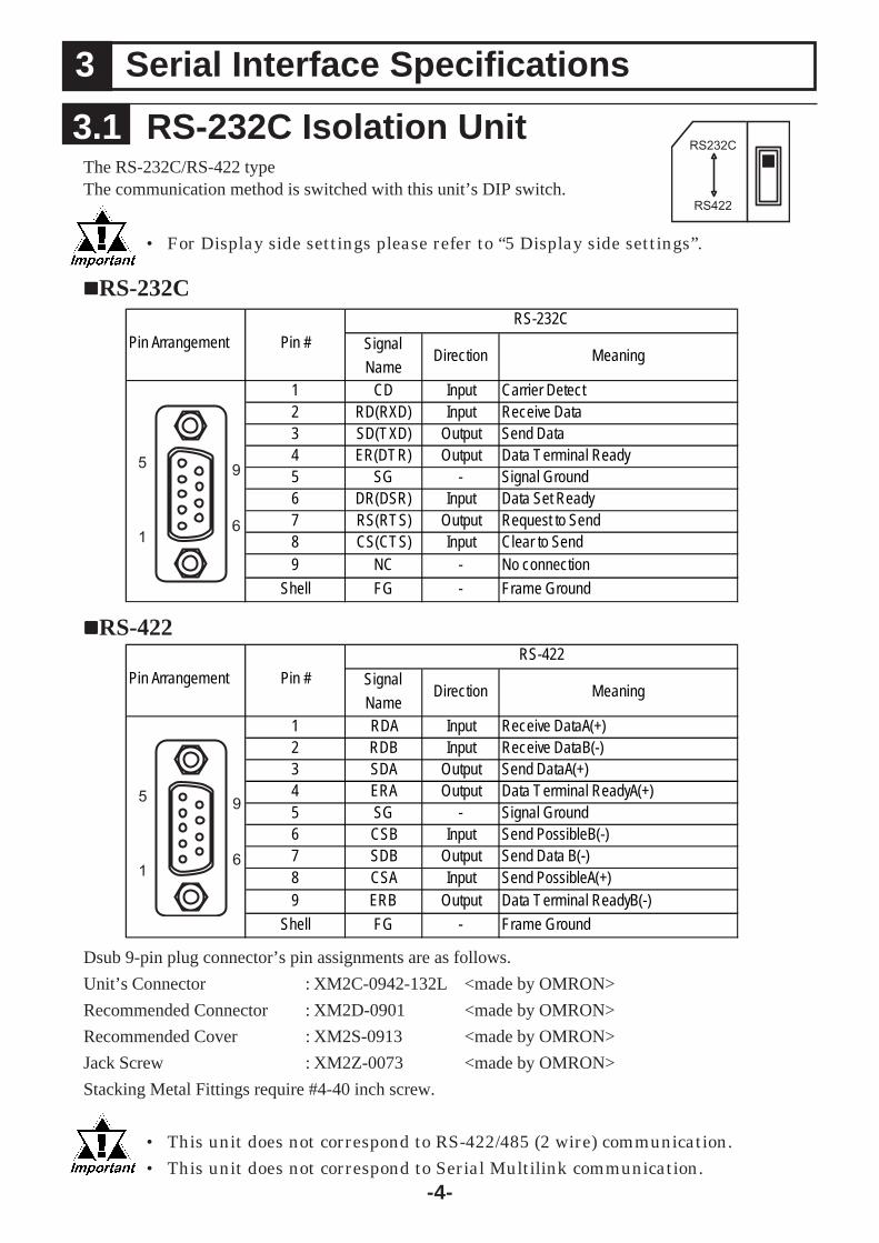
The RS-232C/RS-422 typeThe communication method is switched with this unit’s DIP switch.
• For Display side settings please refer to “5 Display side settings”.
Dsub 9-pin plug connector’s pin assignments are as follows.Unit’s Connector : XM2C-0942-132L <made by OMRON>Recommended Connector : XM2D-0901 <made by OMRON>Recommended Cover : XM2S-0913 <made by OMRON>Jack Screw : XM2Z-0073 <made by OMRON>Stacking Metal Fittings require #4-40 inch screw.
• This unit does not correspond to RS-422/485 (2 wire) communication.• This unit does not correspond to Serial Multilink communication.
Signal
NameDirection Meaning
1 CD Input Carrier Detect2 RD(RXD) Input Receive Data3 SD(TXD) Output Send Data4 ER(DTR) Output Data Terminal Ready5 SG - Signal Ground6 DR(DSR) Input Data Set Ready7 RS(RTS) Output Request to Send8 CS(CTS) Input Clear to Send9 NC - No connection
Shell FG - Frame Ground
Pin Arrangement Pin #
RS-232C
Signal
NameDirection Meaning
1 RDA Input Receive DataA(+)2 RDB Input Receive DataB(-)3 SDA Output Send DataA(+)4 ERA Output Data Terminal ReadyA(+)5 SG - Signal Ground6 CSB Input Send PossibleB(-)7 SDB Output Send Data B(-)8 CSA Input Send PossibleA(+)9 ERB Output Data Terminal ReadyB(-)
Shell FG - Frame Ground
Pin Arrangement Pin #
RS-422
RS-232C
RS-422
3.1 RS-232C Isolation Unit
3 Serial Interface Specifications
5
1
9
6
5
1
9
6
RS232C
RS422

-5-
The RS-485/RS-422 typeThe communication method is switched with a change switch.
Dsub 9-pin socket connector's pin assignments are as follows.
Unit’s Connector : XM3B-0942-132L <made by OMRON>Recommended Connector : XM2A-0901 <made by OMRON>Recommended Cover : XM2S-0913 <made by OMRON>Jack Screw : XM2Z-0073 <made by OMRON>Stacking Metal Fittings require #4-40 inch screw.
*1 The VCC output for Pin #6 is not protected against overcurrent. To prevent damage or unit mal-functions, use only the rated current.
RS422
RS485
.3.2 RS-485 Isolation Unit
Signal
NameDirection Meaning
1 TRMRX -Termination
(Receive side:100Ω)2 - -3 Input/Output Receive/Send DataA(+)4 NC - No connection5 SG - Signal Ground6 VCC - +5V±5% output 0.05A*1
7 - -8 Input/Output Receive/Send DataB(-)
9 TRMTX -Termination
(Send side:100Ω)
Shell FG - Frame Ground
Pin Arrangement Pin #
RS-485
RDB/SDB
RDA/SDA
RS-485
5
1
9
6
RS-422
Signal
NameDirection Meaning
1 TRMRX -Termination
(Receive side:100Ω)2 RDA Input Receive DataA(+)3 SDA Output Send DataA(+)4 NC - No connection5 SG - Signal Ground6 VCC - +5V±5% output 0.05A*1
7 RDB Input Receive DataB(-)8 SDB Output Send DataB(-)
9 TRMTX -Termination
(Send side:100Ω)
Shell FG - Frame Ground
Pin Arrangement Pin #
RS-422
5
1
9
6

-6-
Attaching the unit directly to the Display
1) Attach one screw to the Display’s rear face. The torque should be 0.5Nm to0.6Nm.
2) Attach this unit to the Display.
3) Slide the unit in the direction the arrow shows so that the unit gets caught by the attached screw of 1).
4) Fix the unit with another screw. The torque should be 0.5Nm to 0.6 Nm.
Rear face of Display
Rear face of Display
Rear face of Display
Rear face of Display
When attaching this unit to the rear side of the Display, place it on the rear side of theDisplay in the vertical or horizontal direction using two of the four screws as shownbelow and attach it there.If a different unit is attached to the Display, the attachmentdirection of this unit might be restricted.
4 Attachment Method
75[2.95]
75[2
.95]
EXT*

-7-
• When attaching another unit to the Display, be careful of theplace for the attachment.
• If this unit and Pro-face Product, VM Unit (GP2000-VM41) areattached to AGP-35*0T at the same time,only when this unit isattached in the position as shown below, it's possible to attachthe VM Unit with it at the same time.
VM Unit
• Be careful of the attachment position when attaching this unit to the Display.• Be sure to attach this unit to a stable surface.Do not leave the
unit hanging by its cord.• Be fully careful of wiring. When cords overlap, they may cause noise.
totoAGPAGP
correct Incorrect
totoAGPAGP
totoAGPAGP

-8-
Digital Electronics Corporation8-2-52 Nanko Higashi, Suminoe-ku, Osaka559-0031, JapanURL : http://www.pro-face.com/
NotePlease be aware that Digital Electronics Corpora-tion shall not be held liable by the user for any dam-ages, losses, or third party claims arising from theuses of this product.
When connecting the RS-232C isolation unit, the following two settings are made in theDisplay’s Offline mode or using the screen creation software GP-Pro EX.-Setting the Display’s communication method to RS-232C-Setting the COM1 port’s number 9 pin to VCC
In the case of the operation in the Offline mode, change it with [Peripheral Settings] of[Device PLC/Settings]. For the software(GP-Pro EX)’s operation, refer to “GP-Pro EXDevice/PLC Connection Manual”.
Attaching the unit to the panelWhen attaching the unit to a panel other than the Display main unit, attach it at twopoints referring to the diagram below. Make holes suitable for the screws referring tothe diagram below. For attaching it, refer to “ Attaching the unit directly to theDisplay”.
Unit mm:[in.]
75[2.95]
φ9±0.1[0.35±0.00]
0.7±0.1[0.03±0.00]
(2.7[0.11])
φ6.5±0.1
3.3±0.05[0.13±0.00]4
+0-0.2
M3 SCREW[0.16 ]+0.00-0.01
[0.26±0.00]
2-M3[0.12] or less
5 Display side settings


![Toto the Best of Toto Full Band Score[1]](https://static.fdocuments.us/doc/165x107/54580b1fb1af9fbd038b46a4/toto-the-best-of-toto-full-band-score1.jpg)