Nomenclature Naming Compounds. Naming Binary Ionic Compounds.

!!!!! ! ! !!!!!!!!!!
!
!!!Accelerator Division !!!!!!!!!!
Garry Trahern
ESS Naming Convention
17 May 2011
ESS AD Technical Note ESS/AD/0005
!

ESS Naming Convention
Naming Convention
Revision: 1.2
Status: Accepted
Project: ESS Naming Convention
Document ID: ESS/AD/0005
File: ESS Naming Convention.doc
Owner: Garry Trahern
Last modification: Maay 17, 2011
Created: October 26, 2010
Document History
Revision
Date Changed/ reviewed
Section(s) Modification
1.0
2010/10/26 Garry Trahern
All Initial version
1.1 2010/11/16 Garry Trahern
All Clarify syntax for system/subsystem instantiation TOC formatting
1.2 2011/03/21 Garry Trahern
All Updated examples, moved reference tables to separate document
Confidentiality
This document is classified as a public document. As such, it or parts thereof are openly accessible to anyone listed in the Audience section, either in electronic or in any other form.
Scope
This document represents the basic definitions for the ESS naming convention. It includes the definition of the convention, reference tables and further examples.
Audience
This document is targeted at ESS staff.
Table of Contents
1. Naming convention scope 4!
2. Format and syntax definition 5!2.1. Syntax rules .............................................................................................................. 6!
2.1.1. General guidelines ........................................................................................... 6!2.2. Type reference and attributes ................................................................................... 7!
2.2.1. Device type reference ...................................................................................... 7!2.2.2. Device attribute ................................................................................................ 7!2.2.3. Example ........................................................................................................... 8!
2.3. Conventional facility naming ..................................................................................... 8!
3. Examples 9!3.1. DTL magnet power supply ........................................................................................ 9!3.2. System and subsystem instancing ........................................................................... 9!3.3. Conventional facilities ............................................................................................... 9!

3.4. More examples ....................................................................................................... 10!
4. References 11!Appendix A. Naming convention tools and consistency 12!
Figures
Figure 1: A mockup GUI of a naming convention tool ................................. 10
Tables
Table 1: Naming convention components ........................................................... 6
Acknowledgement We have created this document after referring to naming conventions adopted at many other facilities: SNS, FRIB, ITER, CEBAF as well as earlier ESS naming conventions studies. In particular the system, subsystem and device identifiers from SNS have been borrowed (with some modifications) in the writing of the supporting documents listed in the references. We gratefully acknowledge the use of ideas and nomenclature as well as conversations with personnel from these institutions.
A.1. Naming convention tool / software ....................................................................................................................... 12!A.2. IOC variable name checking ................................................................................................................................ 12!

1. NAMING CONVENTION SCOPE
These requirements apply to all devices (beam instrumentation, sensors, actuators, etc.), equipment (power supplies, magnets, RF cavities, targets, moderators, instruments, etc.) and signals in technical systems and conventional facilities. The naming syntax does not apply to cable or pipe numbering, though cables, pipes and other items may be subsumed in the convention at a later date. The designations listed are to be used on operator screens, in the inventory system, drawings, design schematics, computer software, project databases, equipment name tags, test procedures, and other sources of technical information at ESS. The guiding principle for this document is that a uniform naming convention for ESS will help enforce system integration activities across all divisions.

2. FORMAT AND SYNTAX DEFINITION
The format of names (also called Process Variables in EPICS based Control Systems (CS) for those names which also reside in the CS) shall be as shown below. Further explanations of each component of the naming convention elements are listed in Table 1.
SSSS-BBBB:DDDD-III:TTTIIIXXX
Various examples for system and subsystem components are listed in reference 1. Device identifier examples are listed in reference 2.
This naming convention does not specify minimum or maximum lengths of the name components. However, there is one practical restriction on the overall length of a signal name in the Control System: the current EPICS version can only handle signal names of less than or equal to 28 characters in length. While this restriction will probably be eliminated in a future version, signal names to be implemented in EPICS in the near term should be limited to a length of 28 characters or less. Tests within EPICS are currently being conducted to determine whether this constraint remains necessary. Since the naming convention is a very important part of the over all system integration activities, we feel that this restriction will not present a problem in defining names for ESS.
System and subsystem name
Device identifier and quantifier
Signal type, instance and suffix
Device part Signal part
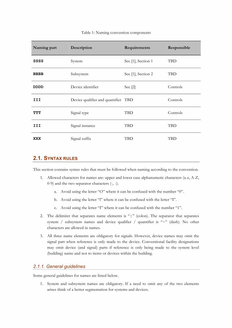
Table 1: Naming convention components
Naming part Description Requirements Responsible
SSSS System See [1], Section 1 TBD
BBBB Subsystem See [1], Section 2 TBD
DDDD Device identifier See [2] Controls
III Device qualifier and quantifier TBD Controls
TTT Signal type TBD Controls
III Signal instance TBD TBD
XXX Signal suffix TBD TBD
2.1. SYNTAX RULES
This section contains syntax rules that must be followed when naming according to the convention.
1. Allowed characters for names are: upper and lower case alphanumeric characters (a-z, A-Z, 0-9) and the two separator characters (-, :).
a. Avoid using the letter “O” where it can be confused with the number “0”.
b. Avoid using the letter “l” where it can be confused with the letter “I”.
c. Avoid using the letter “I” where it can be confused with the number “1”.
2. The delimiter that separates name elements is “:” (colon). The separator that separates system / subsystem names and device qualifier / quantifier is “-” (dash). No other characters are allowed in names.
3. All three name elements are obligatory for signals. However, device names may omit the signal part when reference is only made to the device. Conventional facility designations may omit device (and signal) parts if reference is only being made to the system level (building) name and not to items or devices within the building.
2.1.1. General guidelines
Some general guidelines for names are listed below.
1. System and subsystem names are obligatory. If a need to omit any of the two elements arises think of a better segmentation for systems and devices.
2. If additional segmentation of the system or subsystem is required or for better clarity, an instance number can be appended to the system and subsystem name.
3. Name elements shall be composed with suitable and logical use of lower and upper case component names.
4. Device identifiers and quantifiers are obligatory unless there is only one instance present. Before the quantifier is omitted it is recommended to analyze the risk of doing so.
5. The number of devices and the scope of the devices should define the instancing (e.g. “-001”, “-A01”, “-1”).
6. The device quantifier can also be descriptive if the scope of the devices allows (e.g. high pressure – “-HP” – instead of “-001”).
7. Signal instance can be omitted if there is only an individual signal present.
8. Vendor specific naming should be avoided; the same goes for funny, contemporary or otherwise “meaningful” names.
9. It is advised to use fixed-width fonts (e.g. Courier New) when using variable names in any documentation, examples …
2.2. TYPE REFERENCE AND ATTRIBUTES
A name is composed of a device part (SSSS-BBBB:DDDD-III) and a signal part (TTTIIIXXX). The signal part is intrinsic to the Control System. The device part, however, can be used as the general designation for any part of the ESS infrastructure whether in controls or other technical systems and conventional facilities. Since the device part is constrained by nature of being a mnemonic, various type reference and attribute information may be required to fully understand the nature of an instantiated device. We explain these in the following two sub-sections.
2.2.1. Device type reference
A device type reference is defined as TTTTTTTTTT and represents a class of objects having the same set of characteristics.
Type references will be used as pointers to drawing schematics as well as purchasing information contained elsewhere in ESS technical information systems. As such the type reference identifier must be defined in co-ordination with the design team in the ESS project office.
2.2.2. Device attribute
A device attribute is defined as EEEEEE and is used to distinguish one instance of the same type reference from another.
Attribute information for a device type reference can be various. It may be stored elsewhere in ESS technical content management systems (TCMS). Consequently such attribute information will also be associated with an identifier (e.g., a web page link is possible) that conveniently allows access to this information.

2.2.3. Example
For example, there may be several types of valves used in ESS.
Valves with similar characteristics (size, shape, and manufacturer) are of the same type reference. This type reference is then used to reference part lists and purchasing information.
Each such valve type can then be distinguished by other attributes such as fluid type, pressure, temperature, etc.
2.3. CONVENTIONAL FACILITY NAMING
As mentioned earlier there are parts of the ESS complex that might escape being named by this convention. Pipes, cables and other structures in conventional facilities are potential examples. However, given that we will have type reference and attribute information available (see section [2.2] above) which link to other technical information systems and can provide additional information, we should try and use the naming syntax for everything in conventional facilities if possible. We will go through several examples to make this clearer in section 3.4.

3. EXAMPLES
In order to further clarify the naming convention some basic examples are presented in this section.
3.1. DTL MAGNET POWER SUPPLY
One of the examples would be naming a power supply that services magnets in the DTL system.
The power supply is connected to magnets in the first tank of the DTL system, i.e., DTL1. Additionally the power supply is a part of the Magnets subsystem. Using the tables providing the system and subsystem names the first name element is:
DTL1-Mag
If the power supply is the 10th power supply in a sequence of 20, the device qualifier and quantifier is:
PS-010
Following the same analogy the current (I) setpoint (Set) signal name is:
ISet
The complete name for the command signal is:
DTL1-Mag:PS-010:ISet
The same analogy goes for the current readback signal:
DTL1-Mag:PS-010:IRb
Further examples for Linac, Target systems are listed in section 3.4.
3.2. SYSTEM AND SUBSYSTEM INSTANCING
As indicated in the example above, it is possible to add instance numbers to both the system and subsystem mnemonics. The following example shows proper usage of this syntax.
The second (in a line of n) elliptical cavity sections and the first corresponding cryogenic module (out of m) in that section would have the following system and subsystem name:
EL2-CM1:…
3.3. CONVENTIONAL FACILITIES
The system designation for conventional facilities is CF. Examples of buildings that might be named in CF are:
1. CF-LN Linac tunnel
2. CF-CH1: Cryo facility, (Central Helium liquefier 1)

3. CF-FE5: Front End building 5
4. CF-KL: Klystron Gallery
Inside buildings there will be doors, racks, etc. which also require naming. Examples are
1. CF-LN:Dr-01 : Door 1 in the Linac tunnel
2. CF-FE1:Rack-04: Rack 4 in Front End building 1
3. CF-Pwr2:Twr-01: Electrical tower 1 in power station 2
3.4. MORE EXAMPLES
We will now list further examples from Linac and Target
Linac
1. Src-Vac:Pmp-01 Vacuum pump 1 in Ion Source
2. LEBT-Vac:Pmp-03 Third vacuum pump in LEBT
3. MEBT-Diag:BLM-01 Beam Loss Monitor 1 in MEBT Diagnostic system
4. RFQ-RF:Cpl-01 RFQ RF Coupler 1
5. RFQ-RF:Kly-01 RFQ Klystron 1
6. DTL2-MAG:PMQ-03 DTL Tank 2, Permanent Magnet Quadrupole 3
7. EL1-CM2:Cav-03 Cavity 3 in CryoModule 2 of Elliptical Section 1 (Low Beta)
8. EL2-CM6:QD-01 Defocusing Quadrupole 1 in CryoModule 6 of Elliptical Section 2 (High Beta)
9. EL1-Mag:PS-03 Magnet Power Supply 3 of Elliptical section 1
10. EL2-CM8:BLM-03 Beam Loss Monitor 3 in CryoModule 8 of Elliptical section 2
Target
1. TMod-Cool:IX Ion Exchanger in Thermal Moderator Water Cooling system
2. TMod-Vac:Pmp-01 Pump 1 in Thermal Moderator vacuum system
3. Tgt-Chp:Cu-04 Chopper Unit 4 in Target Chopper system
4. Tgt-Cool:HX Heat Exchanger in Target Water Cooling system
5. HC-PCE:Fan-02 Fan 2 in Hot Cell PCE system
4. REFERENCES
1. ESS Naming Convention reference tables
-- http://eval.esss.lu.se/cgi-bin/public/DocDB/ShowDocument?docid=41
2. ESS device identifiers
-- http://eval.esss.lu.se/cgi-bin/public/DocDB/ShowDocument?docid=42
Appendix A. NAMING CONVENTION TOOLS AND
CONSISTENCY
The name format and list of syntax rules do not automatically make a good naming convention. Therefore the most important aspect of the naming convention is enforcement of the rules.
There are many different approaches to enforce the rules of the naming convention. They range from user-friendly (via applications) to very user-hostile (name checking of the signal names in the input output controllers (IOCs) at boot time). In this section we take a look at some of them.
A.1. NAMING CONVENTION TOOL / SOFTWARE
The best way to enforce naming convention rules is by using a tool that takes care of various naming steps. The possible use-cases for such an application are described in a separated document that is under development.
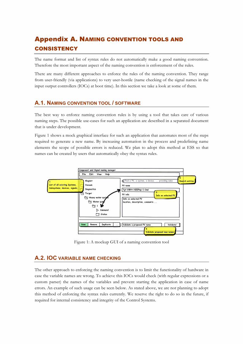
Figure 1 shows a mock graphical interface for such an application that automates most of the steps required to generate a new name. By increasing automation in the process and predefining name elements the scope of possible errors is reduced. We plan to adopt this method at ESS so that names can be created by users that automatically obey the syntax rules.
Figure 1: A mockup GUI of a naming convention tool
A.2. IOC VARIABLE NAME CHECKING
The other approach to enforcing the naming convention is to limit the functionality of hardware in case the variable names are wrong. To achieve this IOCs would check (with regular expressions or a custom parser) the names of the variables and prevent starting the application in case of name errors. An example of such usage can be seen below. As stated above, we are not planning to adopt this method of enforcing the syntax rules currently. We reserve the right to do so in the future, if required for internal consistency and integrity of the Control Systems.

/home/user> ./run_ioc ! ERROR: PV name ‘Tgt:BullsEye-1:Center’ has no subsystem defined! ! The IOC application will now EXIT!