ESS Administration and Reference, Release 19
160
ESS Administration and Reference, Release 19 First Published: 2015-09-30 Last Modified: 2016-10-27 Americas Headquarters Cisco Systems, Inc. 170 West Tasman Drive San Jose, CA 95134-1706 USA http://www.cisco.com Tel: 408 526-4000 800 553-NETS (6387) Fax: 408 527-0883
Transcript of ESS Administration and Reference, Release 19

ESS Administration and Reference, Release 19First Published: 2015-09-30
Last Modified: 2016-10-27
Americas HeadquartersCisco Systems, Inc.170 West Tasman DriveSan Jose, CA 95134-1706USAhttp://www.cisco.comTel: 408 526-4000 800 553-NETS (6387)Fax: 408 527-0883

THE SPECIFICATIONS AND INFORMATION REGARDING THE PRODUCTS IN THIS MANUAL ARE SUBJECT TO CHANGE WITHOUT NOTICE. ALL STATEMENTS,INFORMATION, AND RECOMMENDATIONS IN THIS MANUAL ARE BELIEVED TO BE ACCURATE BUT ARE PRESENTED WITHOUT WARRANTY OF ANY KIND,EXPRESS OR IMPLIED. USERS MUST TAKE FULL RESPONSIBILITY FOR THEIR APPLICATION OF ANY PRODUCTS.
THE SOFTWARE LICENSE AND LIMITEDWARRANTY FOR THE ACCOMPANYING PRODUCT ARE SET FORTH IN THE INFORMATION PACKET THAT SHIPPED WITHTHE PRODUCT AND ARE INCORPORATED HEREIN BY THIS REFERENCE. IF YOU ARE UNABLE TO LOCATE THE SOFTWARE LICENSE OR LIMITED WARRANTY,CONTACT YOUR CISCO REPRESENTATIVE FOR A COPY.
The Cisco implementation of TCP header compression is an adaptation of a program developed by the University of California, Berkeley (UCB) as part of UCB's public domain versionof the UNIX operating system. All rights reserved. Copyright © 1981, Regents of the University of California.
NOTWITHSTANDINGANYOTHERWARRANTYHEREIN, ALL DOCUMENT FILES AND SOFTWARE OF THESE SUPPLIERS ARE PROVIDED “AS IS"WITH ALL FAULTS.CISCO AND THE ABOVE-NAMED SUPPLIERS DISCLAIM ALL WARRANTIES, EXPRESSED OR IMPLIED, INCLUDING, WITHOUT LIMITATION, THOSE OFMERCHANTABILITY, FITNESS FORA PARTICULAR PURPOSEANDNONINFRINGEMENTORARISING FROMACOURSEOFDEALING, USAGE, OR TRADE PRACTICE.
IN NO EVENT SHALL CISCO OR ITS SUPPLIERS BE LIABLE FOR ANY INDIRECT, SPECIAL, CONSEQUENTIAL, OR INCIDENTAL DAMAGES, INCLUDING, WITHOUTLIMITATION, LOST PROFITS OR LOSS OR DAMAGE TO DATA ARISING OUT OF THE USE OR INABILITY TO USE THIS MANUAL, EVEN IF CISCO OR ITS SUPPLIERSHAVE BEEN ADVISED OF THE POSSIBILITY OF SUCH DAMAGES.
Any Internet Protocol (IP) addresses and phone numbers used in this document are not intended to be actual addresses and phone numbers. Any examples, command display output, networktopology diagrams, and other figures included in the document are shown for illustrative purposes only. Any use of actual IP addresses or phone numbers in illustrative content is unintentionaland coincidental.
Cisco and the Cisco logo are trademarks or registered trademarks of Cisco and/or its affiliates in the U.S. and other countries. To view a list of Cisco trademarks, go to this URL: http://www.cisco.com/go/trademarks. Third-party trademarks mentioned are the property of their respective owners. The use of the word partner does not imply a partnershiprelationship between Cisco and any other company. (1110R)
© 2016 Cisco Systems, Inc. All rights reserved.

C O N T E N T S
P r e f a c e About this Guide vii
Conventions Used 9
Additional Information 11
Contacting Customer Support 13
C H A P T E R 1 External Storage System Overview 1
ESS Overview 1
ESS Features and Functions 2
System Requirements 3
ASR 5x00/VPC System Requirements 3
ESS System Requirements 3
ESS System Recommendations for Stand-alone Deployment 4
ESS System Recommendations for Cluster Deployment 6
C H A P T E R 2 Veritas Cluster Installation and Management 11
ESS Cluster Functional Description 12
Installing Hardware 13
Configuring Storage Array on Solaris 15
Configuring Storage using CAM 24
Installing the Management Software (CAM) 24
Accessing the Storage Management GUI 27
Installing the hardware 27
Configuring the Storage System 28
Configuring Veritas Volume Manager and Veritas Cluster 33
Tuning the VxFS File System for Better Performance 36
Configuring Resources for High Availability 37
Creating Disk Group for ESS 39
ESS Administration and Reference, Release 19 iii
Monitoring Veritas Cluster 40
Setup of rootdisk Encapsulation and Mirroring 42
Testing Veritas Cluster 43
ESS Cluster Failure Handling 44
Upgrading from SFHA 5.1SP1 to 6.1/6.1.1 for RHEL 5.9 44
C H A P T E R 3 ESS Installation and Configuration 47
ESS Installation Modes 47
Installing ESS Application in Stand-alone Mode 48
Installing ESS Application in Cluster Mode 57
Uninstalling ESS Application 67
Configuring PSMON Threshold (Optional) 68
C H A P T E R 4 Configuring the ESS Server 71
ESS Server Configuration 71
Source and Destination Configuration 73
Starting and Stopping ESS 78
Restarting LESS 78
Using Veritas Cluster Server 79
Using serv script 81
C H A P T E R 5 L-ESS Deployment in Virtualized Environment 85
Deploying product in Stand-alone mode on KVM-based Guests 85
ESS System Recommendations for KVM-based Guest— Stand-alone Mode 85
Setting-up the environment 86
Deploying product in cluster mode on a KVM-based Guests 97
ESS System Recommendations for KVM-based Guest - Cluster Mode 97
Setting-up the Environment 98
Installing Symantec SFCFSHA in VM Guests 99
Installing L-ESS in cluster mode 99
Deploying product in Stand-alone mode on VMware based Guests 99
ESS System Recommendations for VMware based Guest - Stand-alone Mode 99
Setting-up the environment 100
Deploying Product in Cluster Mode on VMware based Guests 110
ESS System Recommendations for VMware based Guest - Cluster Mode 110
ESS Administration and Reference, Release 19iv
Contents
Setting-up the Environment 111
Installing Symantec SFCFSHA in VM Guests. 127
Installing L-ESS in cluster mode 127
C H A P T E R 6 ESS Maintenance and Troubleshooting 129
Using the Maintenance Utility 129
Using ESS Logs 131
ESS Server Scripts 131
Using the add_project Script 131
Using FSS Scheduler 132
Using Resource Pool Facility 132
Using the start_serv Script 132
Configuring Veritas Cluster to Start ESS Using FSS Scheduler 132
Using the Cleanup Script 133
How the Cleanup Script Works 133
Troubleshooting the ESS 134
Capturing Server Logs Using Script 137
Requirements 137
A P P E N D I X A xDR File Push Functionality 141
Configuring HDD 141
Configuring Push Functionality 142
Pushing xDR Files Manually 143
ESS Directory Structure 144
Log Maintenance 145
ESS Administration and Reference, Release 19 v
Contents

ESS Administration and Reference, Release 19vi
Contents

About this Guide
This document pertains to the features and functionality that are related to the Cisco® ESS Installation andAdministration Guide.
ESS Administration and Reference, Release 19 vii

ESS Administration and Reference, Release 19viii
About this Guide
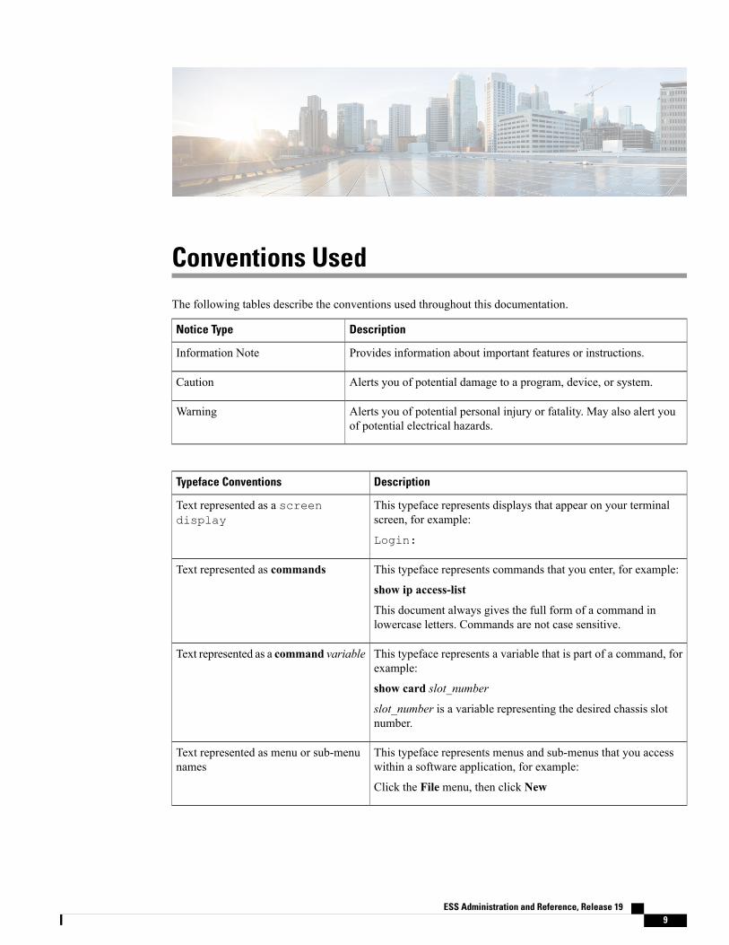
Conventions Used
The following tables describe the conventions used throughout this documentation.
DescriptionNotice Type
Provides information about important features or instructions.Information Note
Alerts you of potential damage to a program, device, or system.Caution
Alerts you of potential personal injury or fatality. May also alert youof potential electrical hazards.
Warning
DescriptionTypeface Conventions
This typeface represents displays that appear on your terminalscreen, for example:
Login:
Text represented as a screendisplay
This typeface represents commands that you enter, for example:
show ip access-list
This document always gives the full form of a command inlowercase letters. Commands are not case sensitive.
Text represented as commands
This typeface represents a variable that is part of a command, forexample:
show card slot_number
slot_number is a variable representing the desired chassis slotnumber.
Text represented as a command variable
This typeface represents menus and sub-menus that you accesswithin a software application, for example:
Click the File menu, then click New
Text represented as menu or sub-menunames
ESS Administration and Reference, Release 19 9

ESS Administration and Reference, Release 1910
Conventions Used

Additional Information
Refer to the following guides for supplemental information about the system:
• Cisco ASR 5000 Installation Guide
• Cisco ASR 5000 System Administration Guide
• Cisco ASR 5x00 Command Line Interface Reference
• Cisco ASR 5x00 Thresholding Configuration Guide
• Cisco ASR 5x00 SNMP MIB Reference
• StarOS IP Security (IPSec) Reference
• Cisco ASR 5x00 AAA Interface Administration and Reference
• Cisco ASR 5x00 GTPP Interface Administration and Reference
• Cisco ASR 5x00 Release Change Reference
• Cisco ASR 5x00 Statistics and Counters Reference
• Cisco ASR 5x00 Gateway GPRS Support Node Administration Guide
• Cisco ASR 5x00 HRPD Serving Gateway Administration Guide
• Cisco ASR 5000 IP Services Gateway Administration Guide
• Cisco ASR 5x00 Mobility Management Entity Administration Guide
• Cisco ASR 5x00 Packet Data Network Gateway Administration Guide
• Cisco ASR 5x00 Packet Data Serving Node Administration Guide
• Cisco ASR 5x00 System Architecture Evolution Gateway Administration Guide
• Cisco ASR 5x00 Serving GPRS Support Node Administration Guide
• Cisco ASR 5x00 Serving Gateway Administration Guide
• Cisco ASR 5000 Session Control Manager Administration Guide
• Cisco ASR 5000 Packet Data Gateway/Tunnel Termination Gateway Administration Guide
• Release notes that accompany updates and upgrades to the StarOS for your service and platform
ESS Administration and Reference, Release 19 11

ESS Administration and Reference, Release 1912
Additional Information

Contacting Customer Support
Use the information in this section to contact customer support.
Refer to the support area of http://www.cisco.com for up-to-date product documentation or to submit a servicerequest. A valid username and password are required to access this site. Please contact your Cisco sales orservice representative for additional information.
ESS Administration and Reference, Release 19 13

ESS Administration and Reference, Release 1914
Contacting Customer Support
C H A P T E R 1External Storage System Overview
The External Storage System (ESS) is used to collect, store, and report billing information from the EnhancedCharging Service running on the ASR 5x00 chassis. This guide contains information on installing, configuring,and maintaining the ESS.
This chapter consists of the following topics:
• ESS Overview, page 1
• System Requirements, page 3
ESS Overview
The ESS is not a part of the ASR5x00 platform or the Enhanced Charging Service (ECS) in-line service.It is an external server.
Important
For information on compatibility between ESS and StarOS releases, contact your Cisco accountrepresentative.
Important
On the ASR 5x00 chassis, the CDR subsystem provides 512 MB of volatile memory on the packet processingcard RAM on the ASR 5000 and the data processing card RAM on the ASR 5500 to store accountinginformation. This on-board memory is intended as a short-term buffer for accounting information so thatbilling systems can periodically retrieve the buffered information for bill generation purposes. However ifnetwork outages or other failures cause billing systems to lose contact with the system, it is possible that theCDR subsystem storage area can be filled with non-retrieved accounting information. When the storage isfilled the CDR subsystem starts deleting the oldest files to make sure that there is room for new billing filesand non-retrieved accounting information can be lost. Using an external storage server with a large storagevolume in close proximity to the chassis ensures room for storing a large amount of billing data that is notlost by any failure.
The ESS has the capability of simultaneously fetching any types of files from one or more chassis. That is, itcan fetch xDRs like CDR, EDR, NBR, UDR file, etc.
ESS Administration and Reference, Release 19 1
In case of Hard Disk Drive (HDD) support on the chassis, the platform has the capability to push the xDRfiles to ESS, and ESS forwards these files to the required destinations. If HDD is not configured on theplatform, ESS pulls the files from the system and forwards them to the destinations. For information on thepush functionality and its configuration, refer to the xDR File Push Functionality appendix.
The ESS is designed to be used as a safe storage area. A mediation or billing server within your network mustbe configured to collect accounting records from the ESS once it retrieves them.
The ESS supports a high level of redundancy for secure charging and billing information for post-processingof xDRs. This system can store charging data of up to 30 days.
The procedures in this guide assume that you have already configured your chassis with ECS as describedin the Enhanced Charging Services Administration Guide.
Important
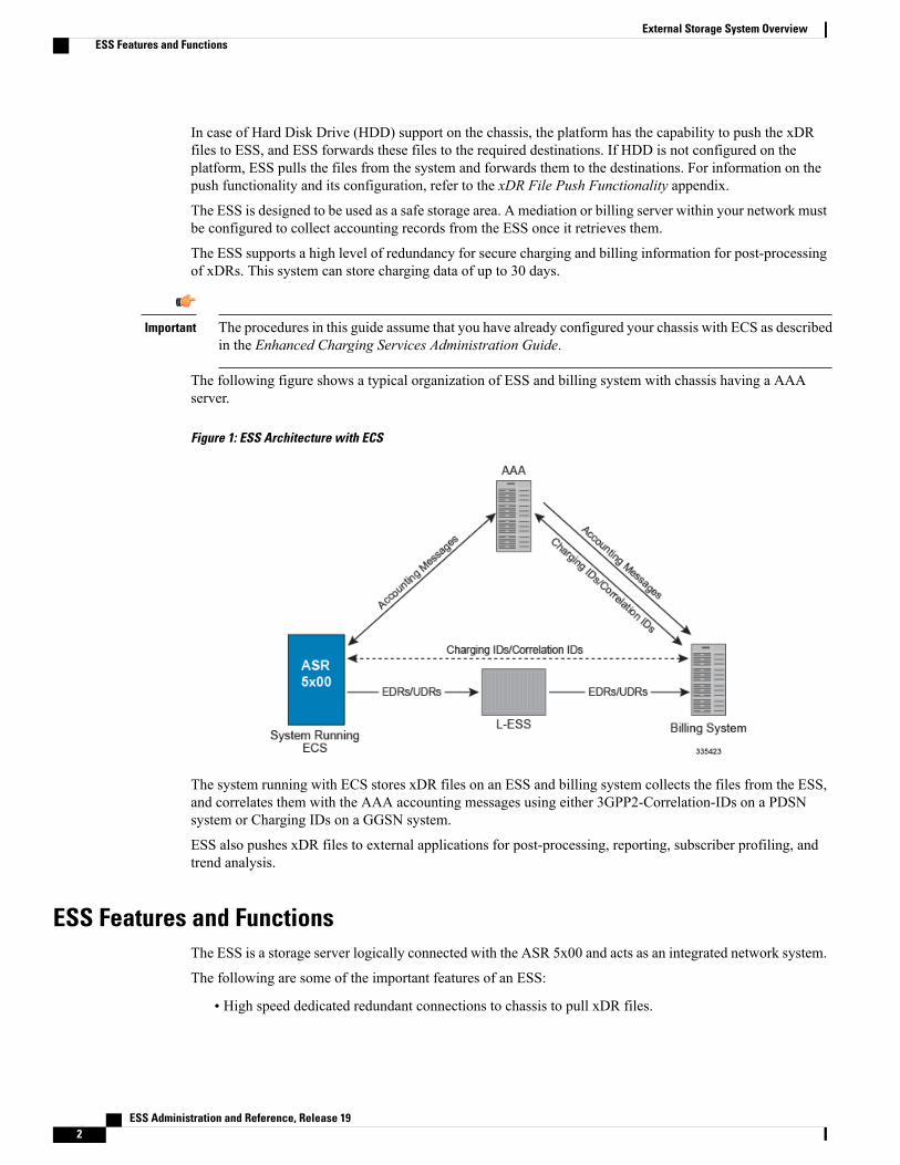
The following figure shows a typical organization of ESS and billing system with chassis having a AAAserver.
Figure 1: ESS Architecture with ECS
The system running with ECS stores xDR files on an ESS and billing system collects the files from the ESS,and correlates them with the AAA accounting messages using either 3GPP2-Correlation-IDs on a PDSNsystem or Charging IDs on a GGSN system.
ESS also pushes xDR files to external applications for post-processing, reporting, subscriber profiling, andtrend analysis.
ESS Features and FunctionsThe ESS is a storage server logically connected with the ASR 5x00 and acts as an integrated network system.
The following are some of the important features of an ESS:
• High speed dedicated redundant connections to chassis to pull xDR files.
ESS Administration and Reference, Release 192
External Storage System OverviewESS Features and Functions
• High-speed dedicated and redundant connection with billing system to transfer xDR files.
• Different management addresses than the management addresses of the chassis and billing system.
• Management interface with support of multiple VLANs.
• Redundancy support with two or more geographically co-located or isolated chassis to pull xDRs.
In general ESS provides the following functions:
• Stores copy of records pulled from chassis.
• Supports storage of up to 7 days worth of records.
• Supports storage capacity of carrier-class redundant.
• Provides a means of limiting the amount of bandwidth, in term of kbps, used for the file transfer betweenchassis and ESS.
• Provides a means of archiving/compression of the pulled xDR files for the purpose of extending thestorage capacity.
• Provides xDR files to the billing system.
System RequirementsThe requirements described in this section must be met in order to ensure proper operation of the ESS system.
ASR 5x00/VPC System RequirementsThe following configurationsmust be implemented, as described inConfiguring Enhanced Charging Serviceschapter of the Enhanced Charging Services Administration Guide:
• ECS must be configured for generating billing records.
• An administrator or config-administrator account that is enabled for FTP must be configured.
• SSH keys must be generated.
• The SFTP subsystem must be enabled.
ESS System Requirements
System requirement recommendation is dependent of different parameters including xDR generation,compression, deployment scenario, etc. Contact your sales representative for system requirements specificto your ESS deployment.
Important
ESS Administration and Reference, Release 19 3
External Storage System OverviewSystem Requirements
ESS System Recommendations for Stand-alone DeploymentThis section identifies the minimum system requirements recommended for the the stand-alone deploymentof the ESS application in 14.0 and later releases:
NEBS Requirements:
• OpenSSL must be installed
• Oracle's Sun Netra™ X4270 M3 Server
◦2 x Intel Xeon processor E5-2600 with 64GB RAM
◦DVD-RW drive
◦Two 100-240V AC (1+1) or two -48V DC or two -60V DC (1+1)
◦Quad Gigabit Ethernet interfaces
• Sun 2540 M2 12 Disk Array AC, Sun 2501 M2 12-Disk Expansion Tray AC
◦12 x 600 GB 2.5" SAS HDD
◦Two redundant AC power supplies
• Operating Environment:
◦Cisco MITG RHEL 5.5
–or–
• Cisco UCS C240 M3
◦2x Intel Xeon X5675 processors with 2x 16 GB DDR3 RAM
◦300GB SAS 10K RPM SFF Hard Disk Drive
◦Quad Gigabit Ethernet interfaces
◦Internal DVD-ROM drive
◦AC or DC power supplies depending on the application
• Sun 2540 M2 12 Disk Array AC, Sun 2501 M2 12-Disk Expansion Tray AC
◦12 x 600 GB 2.5" SAS HDD
◦Two redundant AC power supplies
–or–Oracle FS1 Storage
• FS1-2 Pilot with 2 x Sun Servers X5-2
• HA Controller Pair with 4 x Intel E5-2620 6 Core CPUs
• 64 GB Cache
• 4 x 16 Gbps FC Host Ports
ESS Administration and Reference, Release 194
External Storage System OverviewESS System Requirements
• 24 x 900 GB SAS-2 HDDs
• Operating Environment:
◦Cisco MITG RHEL 5.9
Non-NEBS Requirements:
• Cisco UCS C210 M2 Rack Server
◦2 x Intel Xeon X5675 processor with 64 GB DDR3 RAM
◦300 GB 6Gb SAS 10K RPM SFF Hard Disk Drive
◦Quad Gigabit Ethernet interfaces
◦Internal DVD-ROM drive
◦AC or DC power supplies depending on the application
• Sun 2540 M2 12 Disk Array AC, Sun 2501 M2 12-Disk Expansion Tray AC
◦12 x 600 GB 2.5" SAS HDD
◦Two redundant AC power supplies
• Operating Environment:
◦Cisco MITG RHEL 5.5
The number of discs recommended is based on the throughput of the network and data retentionconfiguration. Please contact Cisco Advanced Service Team for data sizing, number of processors, andRAM size.
Important
The Cisco MITG RHEL v5.5/v5.9 OS is a custom image that contains only those software packagesrequired to support compatible Cisco MITG external software applications. Users must not install anyother applications on servers running the Cisco MITG v5.5/v5.9 OS. For detailed software compatibilityinformation, refer to the Cisco MITG RHEL v5.5/v5.9 OS Application Note.
Important
This section identifies the minimum system requirements recommended for the the stand-alone deploymentof the ESS application in 9.0 and earlier releases:
• OpenSSL must be installed
• Sun Microsystems Netra™ T5220 server
◦1 x 1.2GHz 8 core UltraSPARC T2 processor with 8GB RAM
◦2 x 146GB SAS hard drives
◦Internal CDROM drive
◦AC or DC power supplies depending on your application
ESS Administration and Reference, Release 19 5
External Storage System OverviewESS System Requirements
◦PCI-based video card or Keyboard-Video-Mouse (KVM) card (optional)
◦Quad Gigabit Ethernet interfaces
It is recommended that you have separate interfaces (in IPMP) for mediation device andchassis. Also, for given IPMP, the two interfaces should be on different cards.
Important
• Operating Environment:
◦Sun Solaris 9 with Solaris Patch dated January 25, 2005
◦Sun Solaris 10 with Solaris Patch number 137137-09 dated on or after July 16, 2007 to Nov 2008.
◦Sun Solaris 10 with Solaris-SPARC patch number 126546-07 for SUN bash vulnerability fix.
• PSMON (installed through ESS installation script)
• Perl 5.8.5 (installed through ESS installation script)–or–
• Sun Microsystems Netra™ X4450 server for ESS
◦Quad-Core Intel Xeon E7340 (2x4MB L2, 2.40 GHz, 1066 MHz FSB)
◦32 GB RAM
◦12 x 300 GB 10000 RPM mirrored SAS disks
◦Four 10/100/1000 Ethernet ports, 2 PCI-X, 8 PCIe
◦4 redundant AC power supplies
◦Intel x64 core 4 socket
• Operating Environment:
◦Sun Solaris 10
For information on which server to be used for ESS application, contact your local sales representative.Important
ESS System Recommendations for Cluster DeploymentThis section identifies the minimum system requirements recommended for the the cluster deployment of theESS application in 14.0 and later releases:
NEBS Requirements:
• OpenSSL must be installed
• 2 x Oracle's Sun Netra™ X4270 M3 Server
◦2 x Intel Xeon processor E5-2600 with 64GB RAM
ESS Administration and Reference, Release 196
External Storage System OverviewESS System Requirements
◦DVD-RW drive
◦Two 100-240V AC (1+1) or two -48V DC or two -60V DC (1+1)
◦Quad Gigabit Ethernet interfaces
• Sun 2540 M2 12 Disk Array AC, Sun 2501 M2 12-Disk Expansion Tray AC
◦12x600 GB 2.5" SAS HDD
◦Two redundant AC power supplies
• Veritas cluster version 5.1
• Operating Environment:
◦Cisco MITG RHEL 5.5
–or–
• 2 x Cisco UCS C240 M3
◦2x Intel Xeon X5675 processors with 2x 16 GB DDR3 RAM
◦300GB SAS 10K RPM SFF Hard Disk Drive
◦Quad Gigabit Ethernet interfaces
◦Internal DVD-ROM drive
◦AC or DC power supplies depending on the application
• Sun 2540 M2 12 Disk Array AC, Sun 2501 M2 12-Disk Expansion Tray AC
◦12 x 600 GB 2.5" SAS HDD
◦Two redundant AC power supplies
–or–Oracle FS1 Storage
• FS1-2 Pilot with 2 x Sun Servers X5-2
• HA Controller Pair with 4 x Intel E5-2620 6 Core CPUs
• 64 GB Cache
• 4 x 16 Gbps FC Host Ports
• 24 x 900 GB SAS-2 HDDs
• Veritas cluster version 5.1
• Operating Environment:
◦Cisco MITG RHEL 5.9
Non-NEBS Requirements:
ESS Administration and Reference, Release 19 7
External Storage System OverviewESS System Requirements
• 2 x Cisco UCS C210 M2 Rack Server
◦2 x Intel Xeon X5675 processor with 64 GB DDR3 RAM
◦300GB 6Gb SAS 10K RPM SFF Hard Disk Drive
◦Quad Gigabit Ethernet interfaces
◦Internal DVD-ROM drive
◦AC or DC power supplies depending on the application
• Veritas cluster version 5.1
• Sun 2540 M2 12 Disk Array AC, Sun 2501 M2 12-Disk Expansion Tray AC
◦12 x 600 GB 2.5" SAS HDD
◦Two redundant AC power supplies
–or–Oracle FS1 Storage
• FS1-2 Pilot with 2 x Sun Servers X5-2
• HA Controller Pair with 4 x Intel E5-2620 6 Core CPUs
• 64 GB Cache
• 4 x 16 Gbps FC Host Ports
• 24 x 900 GB SAS-2 HDDs
• Operating Environment:
◦Cisco MITG RHEL 5.5
The number of discs recommended is based on the throughput of the network and data retentionconfiguration. Please contact Cisco Advanced Service Team for data sizing, Number of processors, andRAM size.
Important
The Cisco MITG RHEL v5.5/v5.9 OS is a custom image that contains only those software packagesrequired to support compatible Cisco MITG external software applications. Users must not install anyother applications on servers running the Cisco MITG v5.5/v5.9 OS. For detailed software compatibilityinformation, refer to the Cisco MITG RHEL v5.5/v5.9 OS Application Note.
Important
This section identifies the minimum system requirements recommended for the the cluster deployment of theESS application in 9.0 and earlier releases:
• 2 x Sun Microsystems Netra™ T5220 server
◦1 x 1.2GHz 4 core UltraSPARC T2 processor with 8GB RAM
◦2 x 146GB SAS hard drives
ESS Administration and Reference, Release 198
External Storage System OverviewESS System Requirements

◦Quad Gigabit Ethernet interfaces
It is recommended that you have separate interfaces (in IPMP) for mediation device andchassis. Also, for given IPMP, the two interfaces should be on different cards.
Important
◦Internal CDROM drive
◦AC or DC power supplies depending on your application
• Fiber channel (FC) based Common Storage System for Servers (Sun Storage Tek 2540)
• PCI Dual FC 4GB HBA
• Dual RAID Controllers
• 5 x 300GB 15K drives
• AC or DC power supplies depending upon your application
ESS Administration and Reference, Release 19 9
External Storage System OverviewESS System Requirements

ESS Administration and Reference, Release 1910
External Storage System OverviewESS System Requirements

C H A P T E R 2Veritas Cluster Installation and Management
The cluster mode functionality enables ESS to provide high availability and critical redundancy support toretrieve CDRs in failure of any one of the systems. An ESS cluster comprises of two ESS systems, or nodes,that work together as a single, continuously available system to provide applications, system resources, anddata to ESS users. Each ESS node on a cluster is a fully functional, standalone system. However, in a clusteredenvironment, the ESS nodes are connected by an interconnected network and work together as a single entityto provide increased data availability.
The ESS application consists of internal entities such as the ESS process and process monitor which run ona machine and communicate with the external entities such as the ASR 5x00 chassis. Whenever the machineor ESS process fails, there are chances of loss of communication between internal and external entities. Toavoid downtime and ensure continuous availability of ESS application, High Availability (HA) support usingVeritas Clustering has been provided.
The hardware setup for Veritas Cluster Server (VCS) solution consists of two cluster nodes connected withan external shared storage. Both the cluster nodes are connected to the external storage. Cluster nodes mustbe installed with the Cisco MITG RHEL OS, Veritas Storage Foundation (Veritas Volume Manager andVeritas File System), and Veritas Cluster Server (for High Availability).
The Veritas Volume Manager (VxVM) can be used to create a single disk group (DG) containing multipledisks. Separate disk/LUN from the shared storage is required for I/O fencing. I/O fencing is part of the VCSadministration. It is assumed that I/O fencing is already configured on the Veritas Cluster setup before theESS application is installed for HA.
The cluster setup offers several advantages over traditional single-server systems. These advantages include:
• Support for failover and scalable services
• Capacity for modular growth
• Low entry price compared to traditional hardware fault-tolerant systems
• Reduce or eliminate system downtime because of software or hardware failure
• Ensure availability of data and applications to ESS user, regardless of the kind of failure that wouldnormally take down a single-server system.
• Provide enhanced availability of the system by enabling you to perform maintenance without shuttingdown the entire cluster.
Following are the cluster components that work with ESS to provide this functionality:
• ESS Cluster Node
ESS Administration and Reference, Release 19 11

A ESS cluster node is a ESS server that runs both the ESS Application software and Cluster Agentsoftware. The Cluster Agent enables carrier to network two ESS nodes in a cluster. Every ESS nodein the cluster is aware when another ESS node joins or leaves the cluster. Also, every ESS node in thecluster is aware of the resources that are running locally as well as the resources that are running onthe other ESS cluster nodes.
Each ESS cluster node is a standalone server that runs its own processes. These processes communicatewith one another to form what looks like (to a network client) a single system that co-operativelyprovides applications, system resources, and data to ESS users.
• Common Storage SystemA common storage system is a fiber channel (FC) -based cluster storage with FC drives for the serversin the cluster environment. It is interconnected with ESS cluster nodes with carrier class networkconnectivity to provide high level redundant storage and backup support for CDRs. It serves as commonstorage for all connected ESS cluster nodes.
This system provides high storage scalability and redundancy with RAID support.
Once the Veritas Volume Manager and Veritas Cluster are configured, install the ESS application on theESS Server. For detailed instructions, refer to the ESS Installation and Configuration chapter of this guide.Then, configure the resources for high availability, and perform the cluster monitoring and rootdiskencapsulation processes.
This chapter includes the following topics:
• ESS Cluster Functional Description, page 12
• Installing Hardware, page 13
• Configuring Storage Array on Solaris, page 15
• Configuring Storage using CAM, page 24
• Configuring Veritas Volume Manager and Veritas Cluster, page 33
• Tuning the VxFS File System for Better Performance, page 36
• Configuring Resources for High Availability, page 37
• Monitoring Veritas Cluster, page 40
• Setup of rootdisk Encapsulation and Mirroring, page 42
• Testing Veritas Cluster, page 43
• ESS Cluster Failure Handling, page 44
• Upgrading from SFHA 5.1SP1 to 6.1/6.1.1 for RHEL 5.9, page 44
ESS Cluster Functional DescriptionESS clustering application provides the support to two discreet ESS servers for retrieving and storing xDRsfrom the chassis at a distribution node on a single IP address/network element for the billing system.
Both the ESS nodes (ESS1 and ESS2) are configured identically from the standpoint of the retrieval andstorage of the xDRs to support the following:
ESS Administration and Reference, Release 1912
Veritas Cluster Installation and ManagementESS Cluster Functional Description

• The active ESS (either ESS1 or ESS2) is configured to retrieve xDRs from any and all local chassis inpre-defined intervals and the xDRs are stored on shared disk (between active and standby) by the activeso that whenever active goes down and standby takes over, it has access to fetched data as data is on theshared disk.
• The directory structure of both ESS1 and ESS2 is identical and conform to the carrier standards. A/fetched_data directory under <less_install_dir>/ess is used to store initial retrieval of the xDRs fromthe chassis.
From a process flow perspective, the interaction of the clustered ESS and the ECS is as follows:
• The ESS(s) is statically configured with chassis to pull xDRs.
• The chassis continually generates and groups individual records into xDRs, which are marked as a'closed' xDR file based on pre-defined criteria.
• The active ESS uses SFTP to access the chassis and retrieve all closed xDRs for storage in the/fetched_data directory.
• Active ESS fetches xDR files for eventual retrieval by the billing system.
Installing HardwareTo install the hardware components required for the installation of ESS cluster:
Step 1 Rack the Sun Netra T5220 servers and storage array and connect power to each of them.Step 2 Connect Ethernet port 0 on each server to an Ethernet switch.Step 3 Connect Ethernet port 1 on server 1 to Ethernet port 1 on server 2 with a cross-over cable.Step 4 Connect Ethernet port 2 on server 1 to Ethernet port 2 on server 2 with a cross-over cable.Step 5 Connect a terminal (pc with terminal emulation such as HyperTerm) to the console port. Settings for the console are
9600 8, 1, N. Console cable and DB9 to RJ45 adapter are included with each server.Step 6 Connect one SCSI cable from CH 0 on the Storage Array to Single Bus Conf as shown in the following figure. DO NOT
make any connections to Sun Servers at this time.Step 7 Connect the Ethernet ports on each array controller to an Ethernet switch.Step 8 Insert install DVD into DVD-ROM in the first Sun server. Make sure the server is NOT cabled to the storage array.Step 9 Power on the server.Step 10 Wait for the ok prompt on the console.Step 11 To boot the machine from the DVD, enter:
ok> boot cdrom – installStep 12 The install will run for some time. After the image has been loaded, you will be prompted for the host information shown
below:# Please enter the desired hostname for this machine.# Please enter the desired IP address for bge0.# Please enter the netmask for bge0.# Please enter the default router for bge0.
ESS Administration and Reference, Release 19 13
Veritas Cluster Installation and ManagementInstalling Hardware
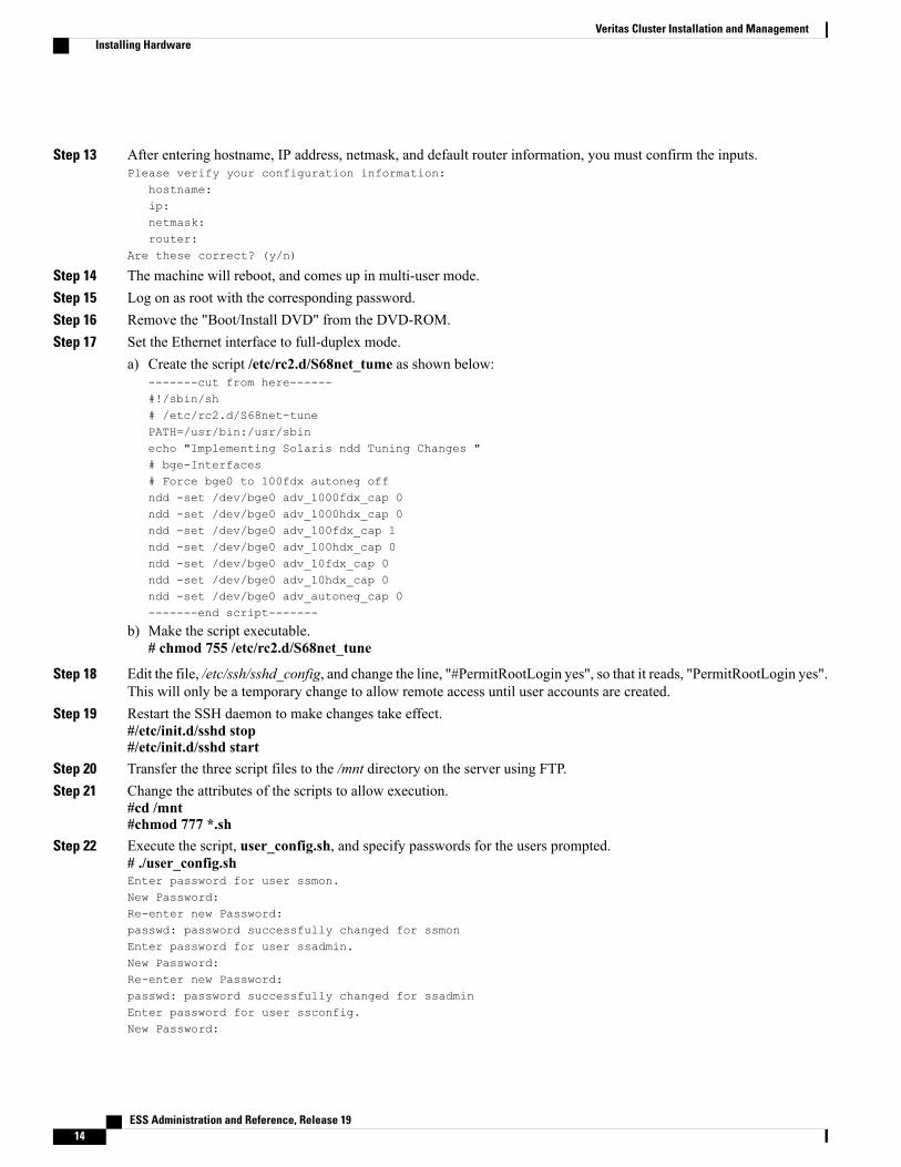
Step 13 After entering hostname, IP address, netmask, and default router information, you must confirm the inputs.Please verify your configuration information:
hostname:ip:netmask:router:
Are these correct? (y/n)
Step 14 The machine will reboot, and comes up in multi-user mode.Step 15 Log on as root with the corresponding password.Step 16 Remove the "Boot/Install DVD" from the DVD-ROM.Step 17 Set the Ethernet interface to full-duplex mode.
a) Create the script /etc/rc2.d/S68net_tume as shown below:-------cut from here------#!/sbin/sh# /etc/rc2.d/S68net-tunePATH=/usr/bin:/usr/sbinecho "Implementing Solaris ndd Tuning Changes "# bge-Interfaces# Force bge0 to 100fdx autoneg offndd -set /dev/bge0 adv_1000fdx_cap 0ndd -set /dev/bge0 adv_1000hdx_cap 0ndd -set /dev/bge0 adv_100fdx_cap 1ndd -set /dev/bge0 adv_100hdx_cap 0ndd -set /dev/bge0 adv_10fdx_cap 0ndd -set /dev/bge0 adv_10hdx_cap 0ndd -set /dev/bge0 adv_autoneg_cap 0-------end script-------
b) Make the script executable.# chmod 755 /etc/rc2.d/S68net_tune
Step 18 Edit the file, /etc/ssh/sshd_config, and change the line, "#PermitRootLogin yes", so that it reads, "PermitRootLogin yes".This will only be a temporary change to allow remote access until user accounts are created.
Step 19 Restart the SSH daemon to make changes take effect.#/etc/init.d/sshd stop#/etc/init.d/sshd start
Step 20 Transfer the three script files to the /mnt directory on the server using FTP.Step 21 Change the attributes of the scripts to allow execution.
#cd /mnt#chmod 777 *.sh
Step 22 Execute the script, user_config.sh, and specify passwords for the users prompted.# ./user_config.shEnter password for user ssmon.New Password:Re-enter new Password:passwd: password successfully changed for ssmonEnter password for user ssadmin.New Password:Re-enter new Password:passwd: password successfully changed for ssadminEnter password for user ssconfig.New Password:
ESS Administration and Reference, Release 1914
Veritas Cluster Installation and ManagementInstalling Hardware
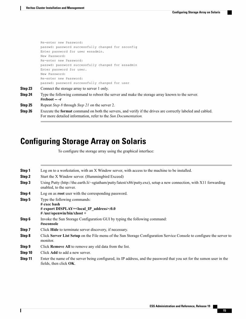
Re-enter new Password:passwd: password successfully changed for ssconfigEnter password for user essadmin.New Password:Re-enter new Password:passwd: password successfully changed for essadminEnter password for user.New Password:Re-enter new Password:passwd: password successfully changed for user
Step 23 Connect the storage array to server 1 only.Step 24 Type the following command to reboot the server and make the storage array known to the server.
#reboot -- -rStep 25 Repeat Step 8 through Step 21 on the server 2.Step 26 Execute the format command on both the servers, and verify if the drives are correctly labeled and cabled.
For more detailed information, refer to the Sun Documentation.
Configuring Storage Array on SolarisTo configure the storage array using the graphical interface:
Step 1 Log on to a workstation, with an X Window server, with access to the machine to be installed.Step 2 Start the X Window server. (Hummingbird Exceed)Step 3 Using Putty (http://the.earth.li/~sgtatham/putty/latest/x86/putty.exe), setup a new connection, with X11 forwarding
enabled, to the server.Step 4 Log on as root user with the corresponding password.Step 5 Type the following commands:
# exec bash# export DISPLAY=<local_IP_address>:0.0# /usr/openwin/bin/xhost +
Step 6 Invoke the Sun Storage Configuration GUI by typing the following command:#ssconsole
Step 7 Click Hide to terminate server discovery, if necessary.Step 8 Click Server List Setup on the File menu of the Sun Storage Configuration Service Console to configure the server to
monitor.Step 9 Click Remove All to remove any old data from the list.Step 10 Click Add to add a new server.Step 11 Enter the name of the server being configured, its IP address, and the password that you set for the ssmon user in the
fields, then click OK.
ESS Administration and Reference, Release 19 15
Veritas Cluster Installation and ManagementConfiguring Storage Array on Solaris
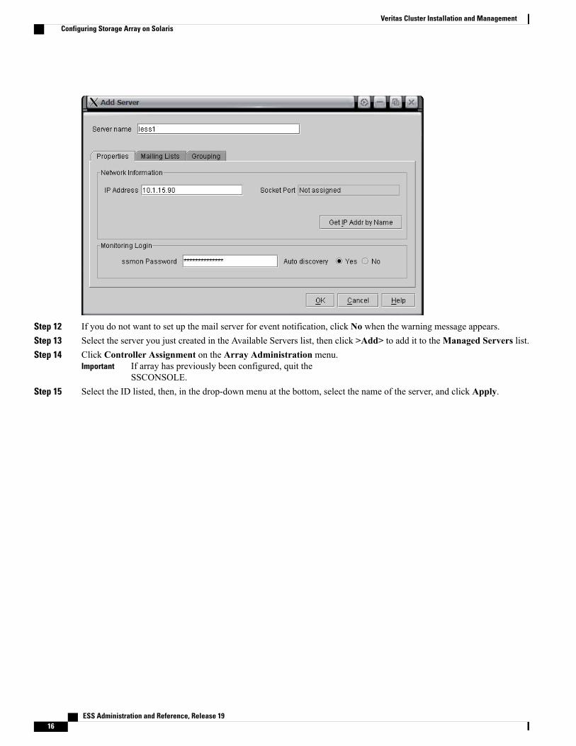
Step 12 If you do not want to set up the mail server for event notification, click No when the warning message appears.Step 13 Select the server you just created in the Available Servers list, then click >Add> to add it to theManaged Servers list.Step 14 Click Controller Assignment on the Array Administration menu.
If array has previously been configured, quit theSSCONSOLE.
Important
Step 15 Select the ID listed, then, in the drop-down menu at the bottom, select the name of the server, and click Apply.
ESS Administration and Reference, Release 1916
Veritas Cluster Installation and ManagementConfiguring Storage Array on Solaris

Step 16 When prompted, enter the password for the ssadmin user that you selected earlier, and then click OK.
Step 17 Click Close.Step 18 Double-click the server in the main dialog. Refer to the following figure for details.Step 19 Double-click the array in the main dialog. Refer to the following figure for details.Step 20 Select the array, and click Standard Configure on the Configuration menu.Step 21 Enter the password for the ssconfig user that you selected earlier.Step 22 Select RAID 5, then select Use a standby drive, andWrite a new label to the new LD check boxes.
ESS Administration and Reference, Release 19 17
Veritas Cluster Installation and ManagementConfiguring Storage Array on Solaris
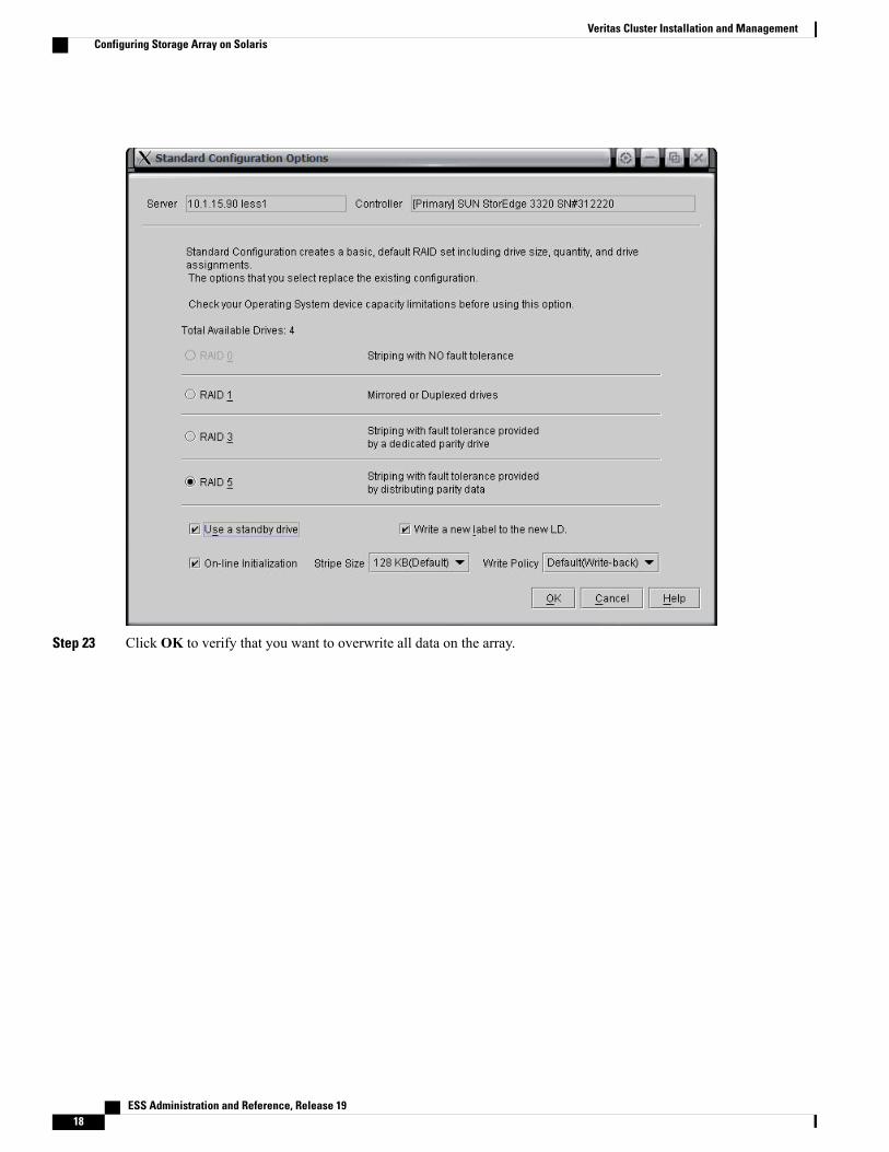
Step 23 Click OK to verify that you want to overwrite all data on the array.
ESS Administration and Reference, Release 1918
Veritas Cluster Installation and ManagementConfiguring Storage Array on Solaris

Step 24 A progress dialog appears showing you the status of the array format.Step 25 When complete, the below dialog appears. Click Close.
Step 26 Click Custom Configure on the Configuration menu.Step 27 Select Change Controller Parameters.
ESS Administration and Reference, Release 19 19
Veritas Cluster Installation and ManagementConfiguring Storage Array on Solaris
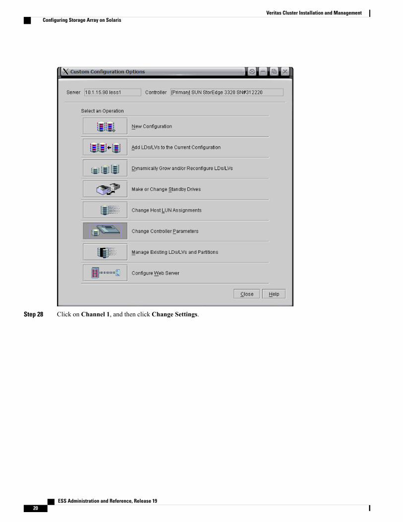
Step 28 Click on Channel 1, and then click Change Settings.
ESS Administration and Reference, Release 1920
Veritas Cluster Installation and ManagementConfiguring Storage Array on Solaris
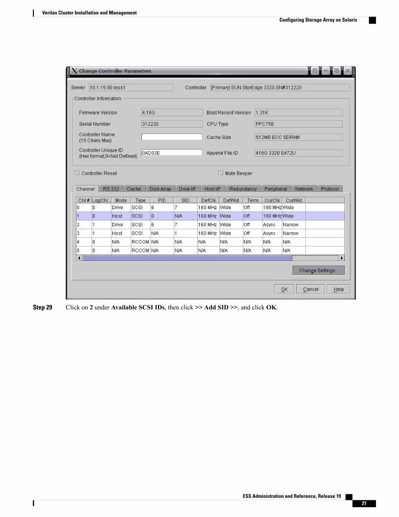
Step 29 Click on 2 under Available SCSI IDs, then click >> Add SID >>, and click OK.
ESS Administration and Reference, Release 19 21
Veritas Cluster Installation and ManagementConfiguring Storage Array on Solaris
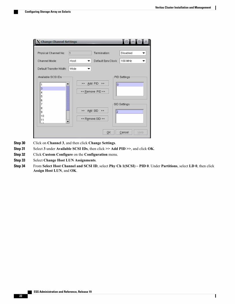
Step 30 Click on Channel 3, and then click Change Settings.Step 31 Select 3 under Available SCSI IDs, then click >> Add PID >>, and click OK.Step 32 Click Custom Configure on the Configuration menu.Step 33 Select Change Host LUN Assignments.Step 34 From Select Host Channel and SCSI ID, select Phy Ch 1(SCSI) – PID 0. Under Partitions, select LD 0, then click
Assign Host LUN, and OK.
ESS Administration and Reference, Release 1922
Veritas Cluster Installation and ManagementConfiguring Storage Array on Solaris

Step 35 Repeat the same for Phy Ch 3(SCSI) – PID 3, and assign LD 0 to it.Step 36 Click Custom Configure on the Configuration menu.Step 37 Select Change Controller Parameters.Step 38 Click on Network tab of the Change Controller Parameters screen, and then click Change Settings.Step 39 Enter the IP address for the array, and subnet mask, then click OK.Step 40 Click Custom Configure on the Configuration menu.Step 41 SelectMake or Change Standby Drives.Step 42 Click the radio button next to, Local Standby for LD#, and make sure that the popup has 0 shown, then click Apply.
ESS Administration and Reference, Release 19 23
Veritas Cluster Installation and ManagementConfiguring Storage Array on Solaris
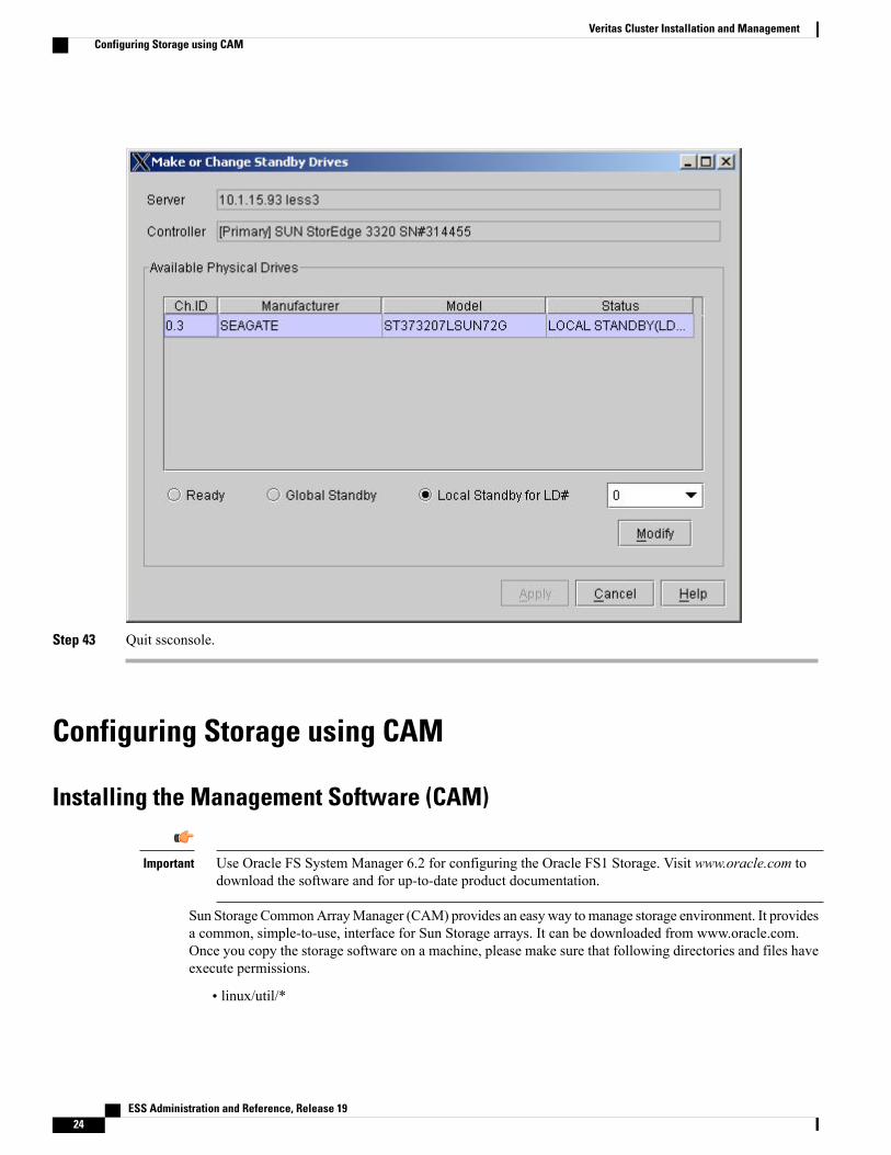
Step 43 Quit ssconsole.
Configuring Storage using CAM
Installing the Management Software (CAM)
Use Oracle FS System Manager 6.2 for configuring the Oracle FS1 Storage. Visit www.oracle.com todownload the software and for up-to-date product documentation.
Important
Sun Storage CommonArrayManager (CAM) provides an easy way tomanage storage environment. It providesa common, simple-to-use, interface for Sun Storage arrays. It can be downloaded from www.oracle.com.Once you copy the storage software on a machine, please make sure that following directories and files haveexecute permissions.
• linux/util/*
ESS Administration and Reference, Release 1924
Veritas Cluster Installation and ManagementConfiguring Storage using CAM
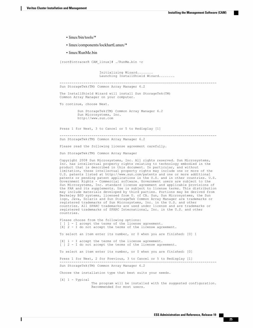
• linux/bin/tools/*
• linux/components/lockhartLunux/*
• linux/RunMe.bin
[root@intracerR CAM_linux]# ./RunMe.bin -c
Initializing Wizard........Launching InstallShield Wizard........
-------------------------------------------------------------------------------Sun StorageTek(TM) Common Array Manager 6.2
The InstallShield Wizard will install Sun StorageTek(TM)Common Array Manager on your computer.
To continue, choose Next.
Sun StorageTek(TM) Common Array Manager 6.2Sun Microsystems, Inc.http://www.sun.com
Press 1 for Next, 3 to Cancel or 5 to Redisplay [1]
-------------------------------------------------------------------------------Sun StorageTek(TM) Common Array Manager 6.2
Please read the following license agreement carefully.
Sun StorageTek(TM) Common Array Manager
Copyright 2008 Sun Microsystems, Inc. All rights reserved. Sun Microsystems,Inc. has intellectual property rights relating to technology embodied in theproduct that is described in this document. In particular, and withoutlimitation, these intellectual property rights may include one or more of theU.S. patents listed at http://www.sun.com/patents and one or more additionalpatents or pending patent applications in the U.S. and in other countries. U.S.Government Rights - Commercial software. Government users are subject to theSun Microsystems, Inc. standard license agreement and applicable provisions ofthe FAR and its supplements. Use is subject to license terms. This distributionmay include materials developed by third parties. Portions may be derived fromBerkeley BSD systems, licensed from U. of CA. Sun, Sun Microsystems, the Sunlogo, Java, Solaris and Sun StorageTek Common Array Manager are trademarks orregistered trademarks of Sun Microsystems, Inc. in the U.S. and othercountries. All SPARC trademarks are used under license and are trademarks orregistered trademarks of SPARC International, Inc. in the U.S. and othercountries.
Please choose from the following options:[ ] 1 - I accept the terms of the license agreement.[X] 2 - I do not accept the terms of the license agreement.
To select an item enter its number, or 0 when you are finished: [0] 1
[X] 1 - I accept the terms of the license agreement.[ ] 2 - I do not accept the terms of the license agreement.
To select an item enter its number, or 0 when you are finished: [0]
Press 1 for Next, 2 for Previous, 3 to Cancel or 5 to Redisplay [1]-------------------------------------------------------------------------------Sun StorageTek(TM) Common Array Manager 6.2
Choose the installation type that best suits your needs.
[X] 1 - TypicalThe program will be installed with the suggested configuration.Recommended for most users.
ESS Administration and Reference, Release 19 25
Veritas Cluster Installation and ManagementInstalling the Management Software (CAM)

[ ] 2 - CustomThe program will be installed with the features you choose.Recommended for advanced users.
Select the number corresponding to the type of install you would like: [0]Press 1 for Next, 2 for Previous, 3 to Cancel or 5 to Redisplay [1]
-------------------------------------------------------------------------------Checking current system ...
|-----------|-----------|-----------|------------|0% 25% 50% 75% 100%||||||||||||||||||||||||||||||||||||||||||||||||||-------------------------------------------------------------------------------Sun StorageTek(TM) Common Array Manager 6.2
Software To Be Installed:Full Install* Browser User Interface (BUI)* Local and Remote CLI* Array Firmware
Press 1 for Next, 2 for Previous, 3 to Cancel or 5 to Redisplay [1] Preparing for installation...
Pre Uninstall Old Action ...
Removing old features ...
-------------------------------------------------------------------------------Sun StorageTek(TM) Common Array Manager 6.2
Installing Sun StorageTek(TM) Common Array Manager 6.2. Please wait...
|-----------|-----------|-----------|------------|0% 25% 50% 75% 100%||||||||||||||||||||||||||||||||||||||||||||||||||
Installing Java 2 Standard Edition
-------------------------------------------------------------------------------Sun StorageTek(TM) Common Array Manager 6.2
|-----------|-----------|-----------|------------|0% 25% 50% 75% 100%||||||||||||||||||||||||||||||||||||||||||||||||||-------------------------------------------------------------------------------Sun StorageTek(TM) Host Software Installation Summary
View results:Info:Installation success.The following have been installed: Browser User Interface (BUI), Local andRemote CLI, and Array Firmware.To access the Browser User Interface point a browser at:https://installation_host:6789The logs may be found in /var/opt/cam/
Press 3 to Finish or 5 to Redisplay [3]
ESS Administration and Reference, Release 1926
Veritas Cluster Installation and ManagementInstalling the Management Software (CAM)
Accessing the Storage Management GUIFollow these steps to access the storage management GUI.
Step 1 Access the Management GUI using a browser on PC (If 65.198.111.26 is the public IP of the node on which themanagement software was installed)https://65.198.111.26:6789
Step 2 The first time login to the CAM software is always through the admin user of the operating system. For example,Administrator on Windows and root on the Unix/Linux.
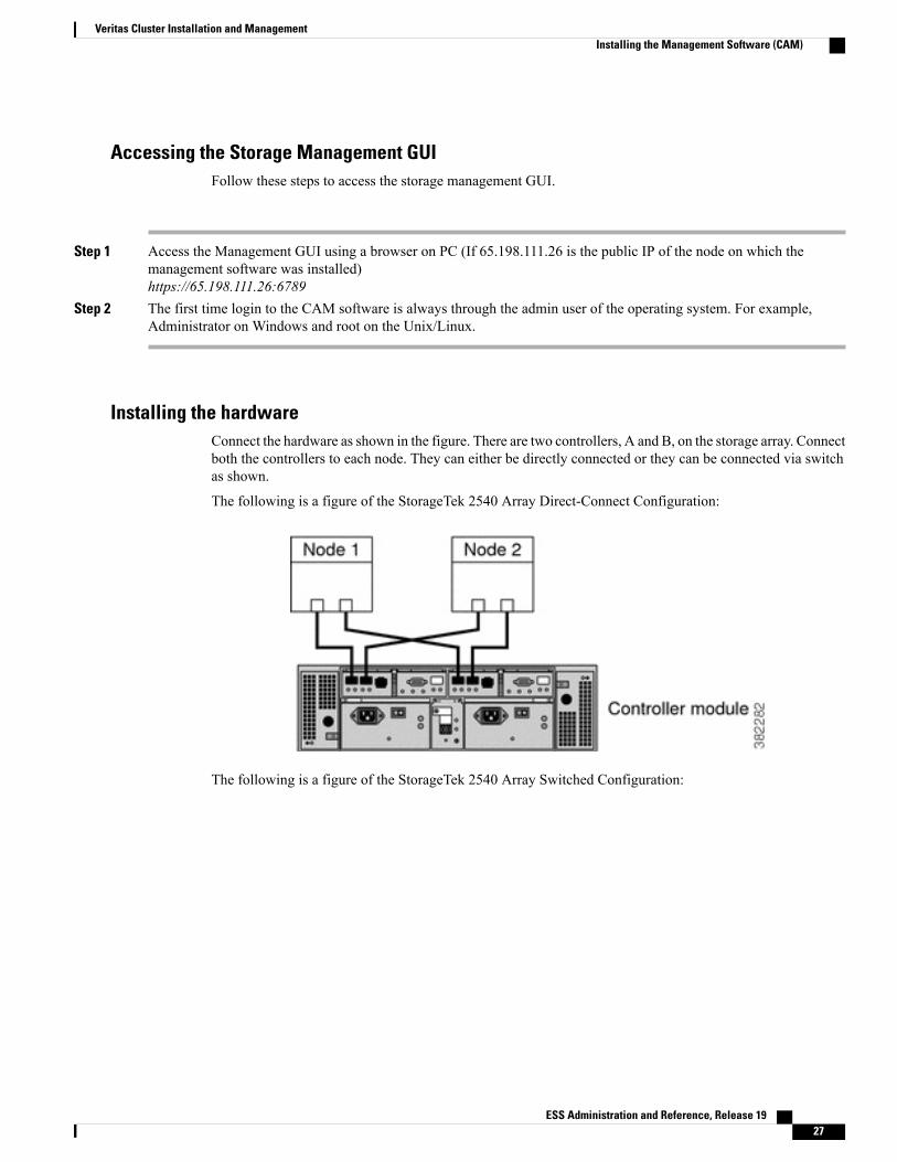
Installing the hardwareConnect the hardware as shown in the figure. There are two controllers, A and B, on the storage array. Connectboth the controllers to each node. They can either be directly connected or they can be connected via switchas shown.
The following is a figure of the StorageTek 2540 Array Direct-Connect Configuration:
The following is a figure of the StorageTek 2540 Array Switched Configuration:
ESS Administration and Reference, Release 19 27
Veritas Cluster Installation and ManagementInstalling the Management Software (CAM)
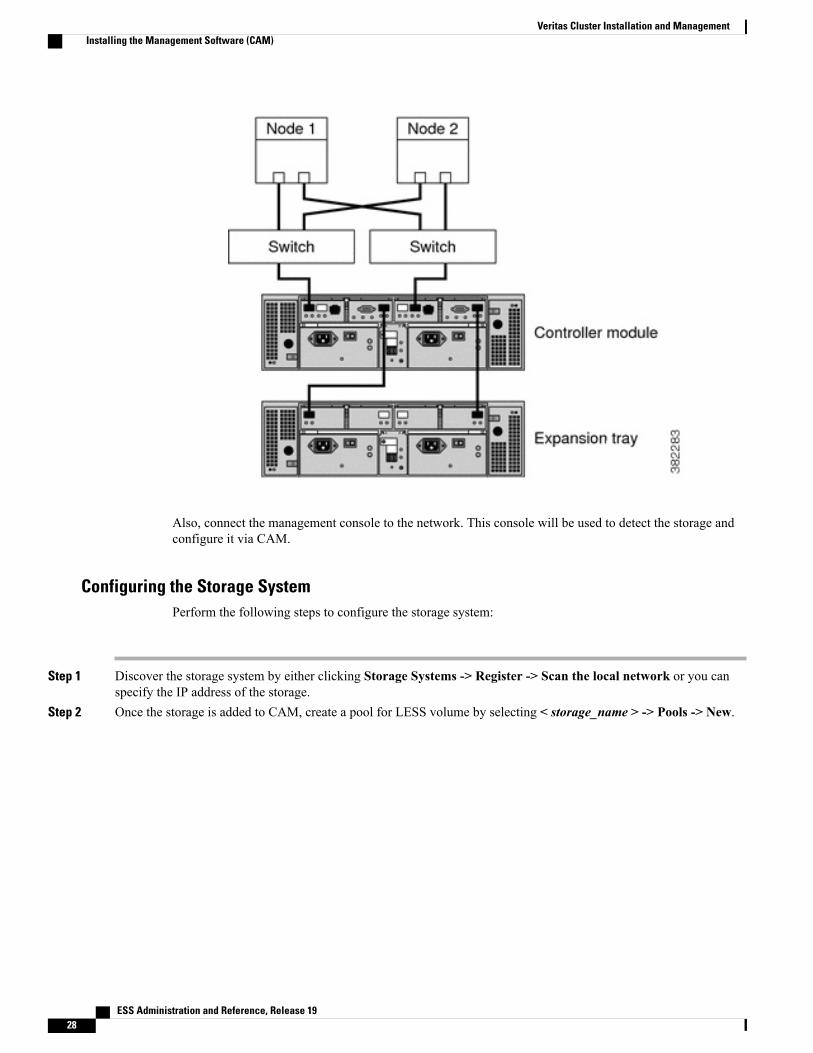
Also, connect the management console to the network. This console will be used to detect the storage andconfigure it via CAM.
Configuring the Storage SystemPerform the following steps to configure the storage system:
Step 1 Discover the storage system by either clicking Storage Systems -> Register -> Scan the local network or you canspecify the IP address of the storage.
Step 2 Once the storage is added to CAM, create a pool for LESS volume by selecting < storage_name > -> Pools -> New.
ESS Administration and Reference, Release 1928
Veritas Cluster Installation and ManagementInstalling the Management Software (CAM)
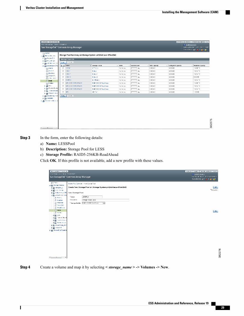
Step 3 In the form, enter the following details:a) Name: LESSPoolb) Description: Storage Pool for LESSc) Storage Profile: RAID5-256KB-ReadAheadClick OK. If this profile is not available, add a new profile with these values.
Step 4 Create a volume and map it by selecting < storage_name > -> Volumes -> New.
ESS Administration and Reference, Release 19 29
Veritas Cluster Installation and ManagementInstalling the Management Software (CAM)
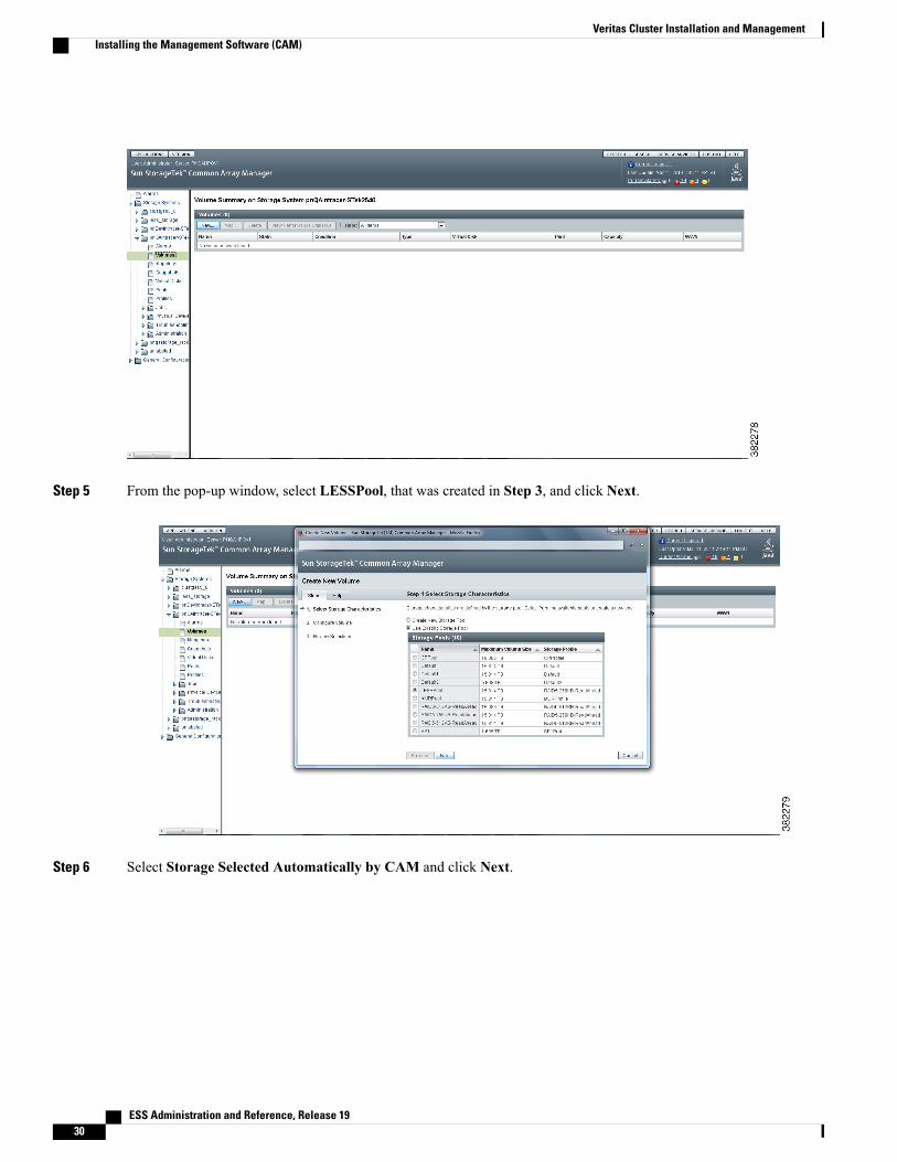
Step 5 From the pop-up window, select LESSPool, that was created in Step 3, and click Next.
Step 6 Select Storage Selected Automatically by CAM and click Next.
ESS Administration and Reference, Release 1930
Veritas Cluster Installation and ManagementInstalling the Management Software (CAM)
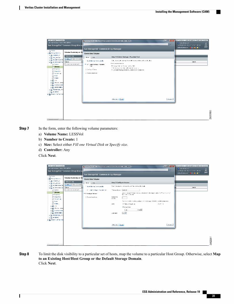
Step 7 In the form, enter the following volume parameters:a) Volume Name: LESSVolb) Number to Create: 1c) Size: Select either Fill one Virtual Disk or Specify size.d) Controller: AnyClick Next.
Step 8 To limit the disk visibility to a particular set of hosts, map the volume to a particular Host Group. Otherwise, selectMapto an Existing Host/Host Group or the Default Storage Domain.Click Next.
ESS Administration and Reference, Release 19 31
Veritas Cluster Installation and ManagementInstalling the Management Software (CAM)
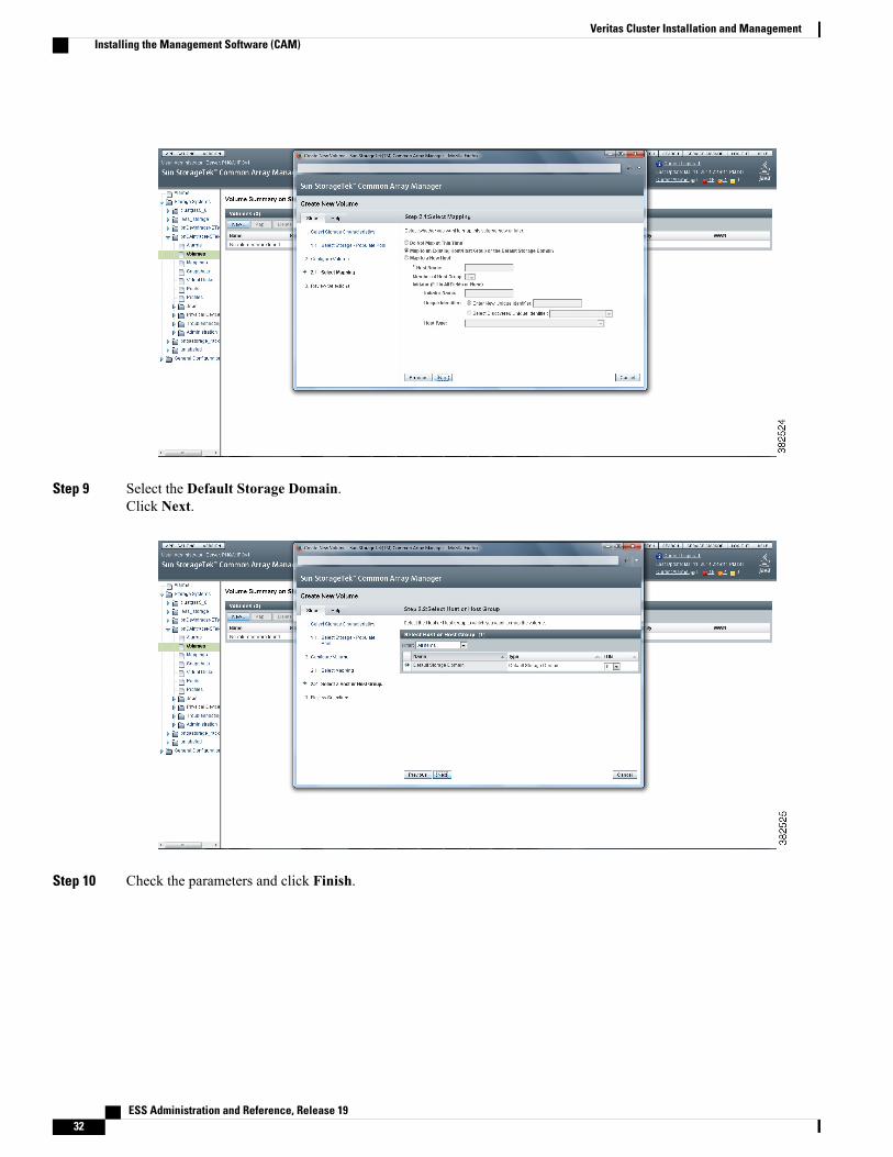
Step 9 Select the Default Storage Domain.Click Next.
Step 10 Check the parameters and click Finish.
ESS Administration and Reference, Release 1932
Veritas Cluster Installation and ManagementInstalling the Management Software (CAM)

Configuring Veritas Volume Manager and Veritas ClusterTo configure the Veritas Volume Manager:
Step 1 Start the installation by entering the following command:vxinstallThe following prompt appears:Are you sure that you want to reinstall [y,n,q,?] (default: n)
Type y if you want to reinstall the Volume Manager.Step 2 Type y to review the licenses that are already installed when the following prompt appears:
Some licenses are already installed. Do you wish to review them [y,n,q] (default: y)
Step 3 Type y when prompted for entering another license key, if necessary. Then enter the key data for this server.The key on the Install DVD is a demo key and will expire in 60days.
Important
Step 4 Press Enter to accept the default of n in the following prompt:Do you want to use enclosure based name for all disks? [y,n,q,?] (default: n)
Step 5 Press Enter to accept the default of y in the following prompt:Do you want to setup a system wide default disk group? [y,n,q,?] (default: y)
Enter a default disk group name of rootdg. The installation of Veritas Volume Manager is now successfully completed.Step 6 Repeat Step 1 through Step 5 on the server 2.Step 7 Copy the provided default LLT and GAB configuration files to configure LLT and GAB. Type the following:
# for file in llttab gabtab llthosts; do cp /etc/$file.server1 /etc/$file; done
ESS Administration and Reference, Release 19 33
Veritas Cluster Installation and ManagementConfiguring Veritas Volume Manager and Veritas Cluster

Step 8 Edit /etc/llttab, if there are more than one cluster on the network. If this is the case, change the cluster ID, after set-clusterto a unique integer. If not, no changes are necessary.
Step 9 Edit /etc/llthosts, and replace less1 with the name of the first server in the pair, and less2 with the name of the secondserver.
Step 10 Restart LLT and GAB, by executing the following commands:#/etc/init.d/gab stop#/etc/init.d/llt.rc stop#/etc/init.d/llt.rc start#/etc/init.d/gab start
Step 11 Repeat Step 7 through Step 10 on second server.Step 12 Verify that both servers' cluster communication modules see each other by typing the following command:
gabconfig –aIf you see a line with membership "01", then both nodes are talking. If you see the message as membership ";1" or "0;"then the node that has the ";" (semi-colon) is misconfigured. Verify your configurations in the /etc/llttab, /etc/llthosts,and /etc/gabtab files.
Step 13 Type hastart and then hastatus. When the last line reads "<system name> RUNNING", VCS engine has started. If youget "VCS ERROR V-16-1-10600 Cannot connect to VCS engine" repeatedly, the VCS engine has failed to start. Referto the /var/VRTSvcs/log/engine_A.log for possible problems.
Step 14 Execute the first VCS configuration script, /mnt/vcs_basic.sh, from the configuration DVD. Enter the data for clusternode names, cluster name, virtual IP address and virtual netmask. A lot of warning messages will be displayed, but thereshould be no errors.
In case of IPv6, enter virtual IPv6 address and the prefix length for virtual IPv6 address. For example:64
Important
Step 15 Stop the cluster by typing the following command:root@less4 # hastop –allThen, copy the new types.cf from the /mnt directory to /etc/VRTSvcs/conf/config.
Step 16 Regenerate and populate the config on both the nodes by executing the following commands:root@less4 # hacf –verify /etc/VRTSvcs/conf/config/root@less4 # hacf –generate /etc/VRTSvcs/conf/config/Then execute hastart on both the nodes.
Step 17 Validate that the cluster has probed all resources by waiting until the hastatus -sum command output looks similar tothe following:root@less4 # hastatus -sum-- SYSTEM STATE-- System State FrozenA less3 RUNNING 0A less4 RUNNING 0-- GROUP STATE-- Group System Prob AutoDisabled StateB LAPP less3 Y N OFFLINEB LAPP less4 Y N OFFLINE
Step 18 Create the resource groups for ESS application and define the dependencies between the resource groups as outlinedbelow.a) Change the VCS configuration as rewritable.
haconf -makerwb) Add the application resource group and change the required attributes.
hares -add <APP_RES> Application lesssghares -modify <APP_RES> Enabled 1
ESS Administration and Reference, Release 1934
Veritas Cluster Installation and ManagementConfiguring Veritas Volume Manager and Veritas Cluster

hares -modify <APP_RES>MonitorProcesses "<ess_installation_directory>/ess/3rdparty/perl/linux//bin/perl-w <ess_installation_directory>/ess/template/psmon --daemon --cron"hares -modify <APP_RES> StartProgram FOR EG /users/ess/start_serv.shhares -modify <APP_RES> StopProgram FOR EG "/users/ess/serv forcestop"hares -modify <APP_RES> User <USERNAME> For EG essadmin
c) Now add the dependencies.hares -link <APP_RES> LESS-VIPhares -link <APP_RES> lessmount
d) To verify the dependencies, enter the following command:hares -disp <APP_RES>The output for this command will display all the required attributes.hares -dep <APP_RES>This command displays the dependencies of the application.
e) Shutdown the ESS.f) Now bring the APP_RES online by entering the following command:
hares -online <APP_RES> -sys <NODE_NAME>g) Once the application is up and running, dump the configuration using the following command:
haconf -dump makeroAlso, perform a cat of main.cf file. A sample output is shown below.
Application T5220-Application (User = rootStartProgram = "/less/LESS/ess/start_serv.sh"StopProgram = "/less/LESS/ess/serv forcestop"MonitorProcesses = { "/less/LESS//ess/3rdparty/perl/linux//bin/perl –w
/less/LESS/ess/template/psmon --daemon --cron" })
// resource dependency tree//// group T5220-SG//
{// Application T5220-Application// {// IP T5220-IP// {// NIC T5220-NIC// }// Mount T5220-mount// {// Volume T5220-Vol// {// DiskGroup T5220-DG// }// }// }// }
h) Perform a switch over and verify that the application comes up on the other node as well.hagrp -offline <RG_name> -sys <Node1>hagrp -online <RG_name> -sys <Node2>
Step 19 Validate that it is online on the first node.root@less4 # hastatus -sum-- SYSTEM STATE
ESS Administration and Reference, Release 19 35
Veritas Cluster Installation and ManagementConfiguring Veritas Volume Manager and Veritas Cluster
-- System State FrozenA less3 RUNNING 0A less4 RUNNING 0-- GROUP STATE-- Group System Probed AutoDisabled StateB LAPP less3 Y NONLINEB LAPP less4 Y NOFFLINE
Step 20 Enable the SNMP traps/alarms and edit the main.cf file under /etc/VRTSvcs/conf/config to add the following entries:NotifierMngr LAPP-Notif-Mgr (
SnmpdTrapPort = 162SnmpConsoles = { "<SNMP_IP_Address>" = Information })
Step 21 Verify and regenerate the new config.root@less3 # hacf –verify /etc/VRTSvcs/conf/config/root@less3 # hacf –generate /etc/VRTSvcs/conf/config/Then, restart both the nodes by executing the following command:root@less3 # hastartroot@less4 # hastartFor more details on the installation of Veritas Volume Manager and Veritas Cluster configuration, refer to the VeritasDocumentation.
Tuning the VxFS File System for Better PerformanceThe VxFS file system can be tuned for better performance using the vxtunefs command to set the tuningparameters. The default values of these parameters are set when the volume is mounted.
The performance of the ESS application can improve when the following tuning parameters are changed:
• read_pref_io: The preferred read request size. The filesystem uses this in conjunction with theread_nstream value to determine how much data to read ahead. The default value is 64000. The ESSperformance can improve when this value is set to 128000.
• read_nstream: This is the desired number of parallel read requests of the size specified in theread_pref_io parameter to have outstanding at one time. The file system uses the value specified in theread_nstream parameter multiplied by the value specified in the read_pref_io parameter to determineits read ahead size. The default value for the read_nstream parameter is 1. If you know the hardwareRAID configuration on the external storage, then set the read_nstream parameter value to be the numberof columns (disks) in the disk array.
• write_pref_io: The preferred write request size. The filesystem uses this in conjunction with the valuespecified in thewrite_nstream parameter to determine how to flush behind on writes. The default valueis 64000. The ESS performance can improve when this value is set to 128K.
• write_nstream: This is the desired number of parallel write requests of the size specified in thewrite_pref_io parameter to have outstanding at one time. The file system uses the value specified inthe write_nstream parameter multiplied by the value specified in the write_pref_io parameter todetermine when to flush behind on writes. The default value for the write_nstream parameter is 1. For
ESS Administration and Reference, Release 1936
Veritas Cluster Installation and ManagementTuning the VxFS File System for Better Performance

disk striping configurations, set the value of the write_pref_io and write_nstream parameters to thesame values as the read_pref_io and read_nstream parameters.
Use the following command to tune Veritas file system:
$ /opt/VRTS/bin/vxtunefs -oread_pref_io=131072,read_unit_io=131072,write_pref_io=131072,write_unit_io=131072 /shared_db
To ensure that these values are not lost after a reboot, create the file /etc/vx/tunefstab using the followingcommand:
$ cat /etc/vx/tunefstab /dev/vx/dsk/apps_dg/apps_volread_pref_io=131072,read_unit_io=131072,write_pref_io=131072,write_unit_io=131072command.
Configuring Resources for High AvailabilityAfter installation of the storage array, Veritas cluster, and the ESS server, the following resources need to beconfigured with the Veritas cluster:
• NIC— To monitor an NIC (Network Interface Card)
• IP— To monitor an IP address
• Disk Group, Volume, and Mount— for shared storage
• ESS Application— comprising of all the ESS-related processes
• Volume—With apps_vol mounted on the /shared_app directory
• ESS installation directory— /shared_apps/less
• ESS Administrator— lessadmin
• Shared/Floating IP address (on NIC eth0)
Figure 2: Resources for high availability
ESS Administration and Reference, Release 19 37
Veritas Cluster Installation and ManagementConfiguring Resources for High Availability

To configure these resources:
The following configurations should be performed only on the node where the ESS application is installed.Important
Step 1 Log on as super user (root).Step 2 Make the veritas config file writable using the following command:
$ haconf -makerwStep 3 Create resource group using the following commands:
$hagrp -add less-ha$hagrp –modify less-ha SystemList <Node1> 0<Node2> 1$hagrp –modify less-ha NumRetries 1Where, Node1 and Node2 are the hostnames of the active and passive nodes.
Step 4 Create Disk Group resource for the ESS partition using the following commands:$ hares -add less-apps-dg DiskGroup less-ha$ hares -modify less-apps-dg DiskGroup apps_dg$ hares -modify less-apps-dg Enabled 1
Step 5 Create Volume resource for the ESS partition using the following commands:$ hares -add less-apps-vol Volume less-ha$ hares -modify less-apps-vol DiskGroup apps_dg$ hares -modify less-apps-vol Volume apps_vol$ hares -modify less-apps-vol Enabled 1
Step 6 Create Mount resource for the ESS partition using the following commands:$ hares -add less-apps-mnt Mount less-ha$ hares -modify less-apps-mnt MountPoint /shared_apps$ hares -modify less-apps-mnt BlockDevice /dev/vx/dsk/apps_dg/apps_vol$ hares -modify less-apps-mnt FSType vxfs$ hares -modify less-apps-mnt FsckOpt %-y$ hares -modify less-apps-mnt MountOpt largefiles$ hares -modify less-apps-mnt Enabled 1
Step 7 Create Application resource for the ESS processes using the following commands:$ hares -add less-app Application less-ha$ hares -modify less-app User lessadmin$ hares -modify less-app StartProgram "/<installed dir>/ess/serv start"$ hares -modify less-app StopProgram "/<installed dir>/ess/serv forcestop"$ hares -modify <APP_RES>MonitorProcesses "<ess_installation_directory>/ess/3rdparty/perl/linux//bin/perl-w <ess_installation_directory>/ess/template/psmon --daemon --cron"$ hares -modify less-app Enabled 1
Step 8 Create the NIC resource using the following commands:$ hares -add less-nic NIC less-ha$ hares -modify less-nic Device eth0$ hares -modify less-nic Protocol IPv6
Use the hares -modify less-nic Protocol IPv6 command only in IPv6setup.
Important
$ hares -modify less-nic Enabled 1Step 9 Create the IP resource using the following commands:
$ hares -add less-ip IP less-ha$ hares -modify less-ip Device eth0
ESS Administration and Reference, Release 1938
Veritas Cluster Installation and ManagementConfiguring Resources for High Availability
• For IPv6 setup:$ hares -modify less-ip Address <ipv6-address>$ hares -modify less-ip PrefixLen 64
• For IPv4 setup:$ hares -modify less-ip Address <ip-address>$ hares -modify less-ip NetMask 255.255.255.0
The floating or shared IP address should be a public IP in the DNS to which the client machine cansuccessfully ping.
Important
$ hares -modify less-ip Enabled 1Step 10 Set the resource dependencies using the following commands:
$ hares -link less-app less-apps-mnt$ hares -link less-apps-mnt less-apps-vol$ hares -link less-apps-vol less-apps-dg$ hares -link less-app less-ip$ hares -link less-ip less-nic
Step 11 Dump the configuration to the Veritas config file using the following command:$ haconf -dump -makero
Step 12 Bring the ESS HA application online on Node 1 using the following command:$ hagrp -online less-ha -sys <Node1>
Once the above steps are performed, the ESS HA application will start running.
Creating Disk Group for ESSUse the following instructions to create disk groups for ESS:
Step 1 Rebuild the disk lists with the new disks detected by the kernel using the following command:$ vxdctl initdmp$ vxdctl enableTo see the status of the new disk, use the command:$ vxdisk -o alldgs listDEVICE TYPE DISK GROUPSTATUSdisk_0 auto:none - -online invaliddisk_1 auto:none - -online invaliddisk_2 auto:none - -online invaliddisk_3 auto:none - -online invalidemc_clariion0_28 auto - -erroremc_clariion0_29 auto - -error
ESS Administration and Reference, Release 19 39
Veritas Cluster Installation and ManagementCreating Disk Group for ESS
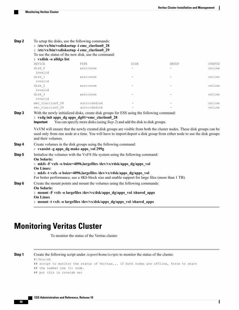
Step 2 To setup the disks, use the following commands:$ /etc/vx/bin/vxdisksetup -i emc_clariion0_28$ /etc/vx/bin/vxdisksetup -i emc_clariion0_29To see the status of the new disk, use the command:$ vxdisk -o alldgs listDEVICE TYPE DISK GROUP STATUSdisk_0 auto:none - - onlineinvaliddisk_1 auto:none - - onlineinvaliddisk_2 auto:none - - onlineinvaliddisk_3 auto:none - - onlineinvalidemc_clariion0_28 auto:cdsdisk - - onlineemc_clariion0_29 auto:cdsdisk - - online
Step 3 With the newly initialized disks, create disk groups for ESS using the following command:$ vxdg init apps_dg apps_dg01=emc_clariion0_28
You can specify more disks (using Step 2) and add the disk to disk groups.Important
VxVM will ensure that the newly created disk groups are visible from both the cluster nodes. These disk groups can beused only from one node at a time. You will have to import/deport a disk group from either node to use the disk groupsand their volumes.
Step 4 Create volumes in the disk groups using the following command:$ vxassist -g apps_dg make apps_vol 299g
Step 5 Initialize the volumes with the VxFS file system using the following command:On Solaris:$ mkfs -F vxfs -o bsize=4096,largefiles /dev/vx/rdsk/apps_dg/apps_volOn Linux:$ mkfs -t vxfs -o bsize=4096,largefiles /dev/vx/rdsk/apps_dg/apps_volFor better performance, use a 4Kb block size and enable support for large files (more than 1 TB).
Step 6 Create the mount points and mount the volumes using the following commands:On Solaris:$ mount -F vxfs -o largefiles /dev/vx/dsk/apps_dg/apps_vol /shared_appsOn Linux$ mount -t vxfs -o largefiles /dev/vx/dsk/apps_dg/apps_vol /shared_apps
Monitoring Veritas ClusterTo monitor the status of the Veritas cluster:
Step 1 Create the following script under /export/home/scripts to monitor the status of the cluster.#!/bin/sh## script to monitor the status of Veritas... if both nodes are offline, force to start## the number one (1) node.## put this in crontab as:
ESS Administration and Reference, Release 1940
Veritas Cluster Installation and ManagementMonitoring Veritas Cluster
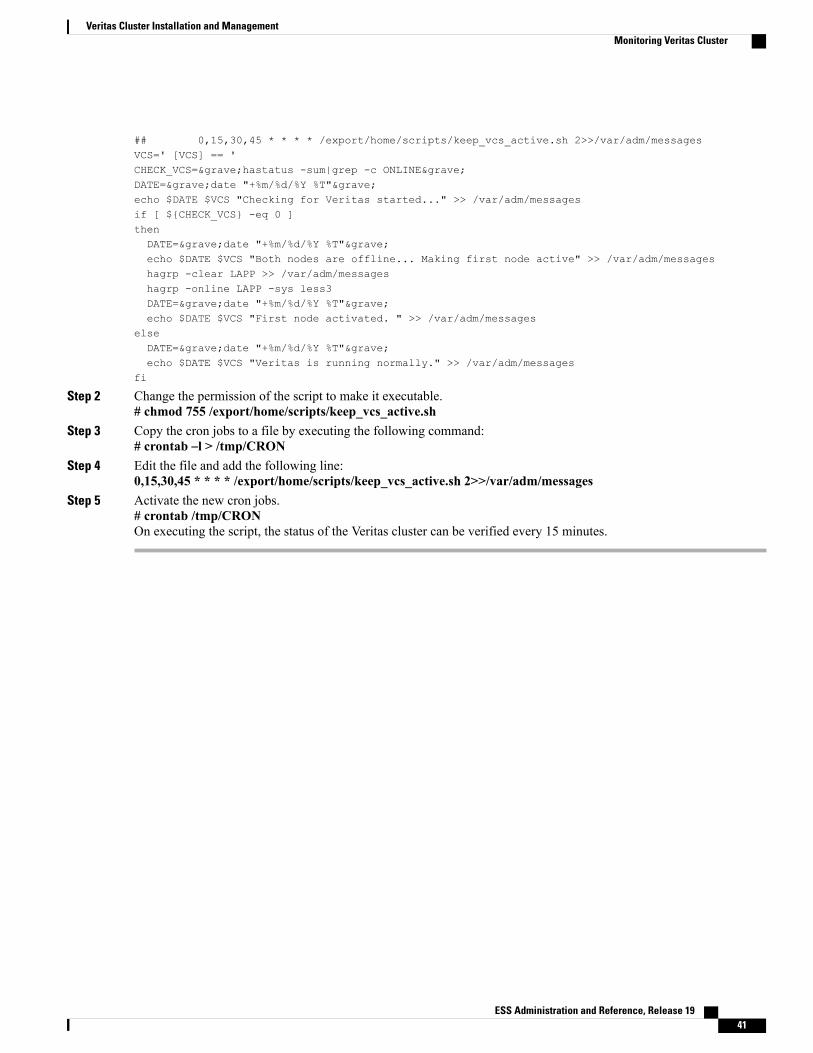
## 0,15,30,45 * * * * /export/home/scripts/keep_vcs_active.sh 2>>/var/adm/messagesVCS=' [VCS] == 'CHECK_VCS=`hastatus -sum|grep -c ONLINE`DATE=`date "+%m/%d/%Y %T"`echo $DATE $VCS "Checking for Veritas started..." >> /var/adm/messagesif [ ${CHECK_VCS} -eq 0 ]thenDATE=`date "+%m/%d/%Y %T"`echo $DATE $VCS "Both nodes are offline... Making first node active" >> /var/adm/messageshagrp -clear LAPP >> /var/adm/messageshagrp -online LAPP -sys less3DATE=`date "+%m/%d/%Y %T"`echo $DATE $VCS "First node activated. " >> /var/adm/messages
elseDATE=`date "+%m/%d/%Y %T"`echo $DATE $VCS "Veritas is running normally." >> /var/adm/messages
fi
Step 2 Change the permission of the script to make it executable.# chmod 755 /export/home/scripts/keep_vcs_active.sh
Step 3 Copy the cron jobs to a file by executing the following command:# crontab –l > /tmp/CRON
Step 4 Edit the file and add the following line:0,15,30,45 * * * * /export/home/scripts/keep_vcs_active.sh 2>>/var/adm/messages
Step 5 Activate the new cron jobs.# crontab /tmp/CRONOn executing the script, the status of the Veritas cluster can be verified every 15 minutes.
ESS Administration and Reference, Release 19 41
Veritas Cluster Installation and ManagementMonitoring Veritas Cluster

Setup of rootdisk Encapsulation and MirroringTo setup the rootdisk encapsulation and mirroring:
Step 1 Log on as super user (root) on the first server. Execute format, and then select disk "1".Step 2 Type y when prompted for labeling the disk.Step 3 Exit format, by pressing CTRL+D.Step 4 Execute vxdiskadm, and select option "2".Step 5 Type list to see a list of available disks.Step 6 Select the rootdisk, "c1t0d0" for encapsulation.Step 7 Verify that the rootdisk is the desired disk to encapsulate.Step 8 Specify rootdg, the default, as the disk group to add the rootdisk to. Then, confirm that rootdg should be created.Step 9 When prompted, type n to specify that you do not wish to use the default disk name for the rootdisk. Then, confirm that
you wish to continue with the encapsulation.Step 10 Enter a name for the rootdisk, and press ENTER to accept the default private region length.Step 11 The rootdisk has been configured for encapsulation. Reboot the server using the following command:
#shutdown –g0 –y –i6Step 12 Repeat Step 1 through Step 11 on the second server.Step 13 Initialize the second disk that was formatted in Step 2.
# vxdisksetup -i c1t1d0 format=slicedStep 14 Add the disk to the rootdg disk group.
# vxdg -g rootdg adddisk rootmirror=c1t1d0s2Step 15 Initialize the mirror process by executing the following command:
# vxrootmir -v rootmirrorThe output should be similar to the following:! vxassist -g bootdg mirror rootvol layout=contig,diskalign rootmirror! vxbootsetup -g bootdg -v rootmirror! vxmksdpart -f -v -g rootdg rootmirror-01 0 0x2 0x200! vxpartadd /dev/rdsk/c1t1d0s2 0 0x2 0x200 20352 62918208! /usr/sbin/installboot /usr/platform/SUNW,Netra-T5220/lib/fs/ufs/bootblk /dev/rdsk/c1t1d0s0! vxeeprom devalias vx-rootmirror /dev/dsk/c1t1d0s0
This process will take a long time. It can be monitored from another terminal by typing vxtaskmonitor.Important
Step 16 Mirror the additional volumes with the following command:# vxmirror rootdisk rootmirrorThe output should be as follows:! vxassist -g defaultdg mirror swapvol rootmirror! vxassist -g defaultdg mirror export rootmirror
This process will take a long time. It can be monitored from another terminal by typing vxtaskmonitor.Important
Step 17 Eject the DVD from the drive, by typing /usr/sbin/umount /mnt and eject /dev/dsk/c0t0d0s0.Step 18 When complete, shut down both the nodes, by typing, hastop –all –force. Then, type hacf –verify
/etc/VRTSvcs/conf/config/ to verify the cluster configuration. Next, type hastart on node 1, then hastatus. On node 2,
ESS Administration and Reference, Release 1942
Veritas Cluster Installation and ManagementSetup of rootdisk Encapsulation and Mirroring

type hastart. The cluster should then start, and can be monitored in the hastatus window open on node 1. Refer to/var/VRTSvcs/log/engine_A.log if you get any errors.
Testing Veritas ClusterThere are two ways to check the status of the cluster, either interactive or by its summary. To verify the status,type the following:
root@LESS1 # hastatusattempting to connect....connectedgroup resource system message-------- -------------------- -------------------- --------------------
JPTRFLGN-LESS1 RUNNINGJPTRFLGN-LESS2 RUNNING
LAPP JPTRFLGN-LESS1 OFFLINELAPP JPTRFLGN-LESS2 ONLINE-----------------------------------------------------------------------LAPP JPTRFLGN-LESS1 OFFLINELAPP JPTRFLGN-LESS2 ONLINE
LAPP-app-ess JPTRFLGN-LESS1 OFFLINELAPP-app-ess JPTRFLGN-LESS2 ONLINELAPP-vmdg-lessdg JPTRFLGN-LESS1 OFFLINE
-----------------------------------------------------------------------LAPP-vmdg-lessdg JPTRFLGN-LESS2 ONLINELAPP-ip-vip_ext JPTRFLGN-LESS1 OFFLINELAPP-ip-vip_ext JPTRFLGN-LESS2 ONLINELAPP-mnt-less JPTRFLGN-LESS1 OFFLINELAPP-mnt-less JPTRFLGN-LESS2 ONLINE
-----------------------------------------------------------------------LAPP-mnt-less-bk JPTRFLGN-LESS1 OFFLINELAPP-mnt-less-bk JPTRFLGN-LESS2 ONLINELAPP-nic-bge0 JPTRFLGN-LESS1 ONLINELAPP-nic-bge0 JPTRFLGN-LESS2 ONLINELAPP-app-ess JPTRFLGN-LESS1 OFFLINE
-----------------------------------------------------------------------LAPP-app-ess JPTRFLGN-LESS2 ONLINELAPP-vmdg-lessdg JPTRFLGN-LESS1 OFFLINELAPP-vmdg-lessdg JPTRFLGN-LESS2 ONLINELAPP-ip-vip_ext JPTRFLGN-LESS1 OFFLINELAPP-ip-vip_ext JPTRFLGN-LESS2 ONLINE
-----------------------------------------------------------------------LAPP-mnt-less JPTRFLGN-LESS1 OFFLINELAPP-mnt-less JPTRFLGN-LESS2 ONLINELAPP-mnt-less-bk JPTRFLGN-LESS1 OFFLINELAPP-mnt-less-bk JPTRFLGN-LESS2 ONLINELAPP-nic-bge0 JPTRFLGN-LESS1 ONLINE
-----------------------------------------------------------------------LAPP-nic-bge0 JPTRFLGN-LESS2 ONLINE
This will continue to gather the status unless interrupted by pressing Ctrl+C key.Important
root@LESS1 # hastatus –sum-- SYSTEM STATE-- System State FrozenA JPTRFLGN-LESS1 RUNNING 0A JPTRFLGN-LESS2 RUNNING 0-- GROUP STATE-- Group System Probed AutoDisabled StateB LAPP JPTRFLGN-LESS1 Y N OFFLINEB LAPP JPTRFLGN-LESS2 Y N ONLINE
ESS Administration and Reference, Release 19 43
Veritas Cluster Installation and ManagementTesting Veritas Cluster
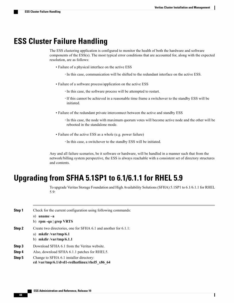
ESS Cluster Failure HandlingThe ESS clustering application is configured to monitor the health of both the hardware and softwarecomponents of the ESS(s). The most typical error conditions that are accounted for, along with the expectedresolution, are as follows:
• Failure of a physical interface on the active ESS
◦In this case, communication will be shifted to the redundant interface on the active ESS.
• Failure of a software process/application on the active ESS
◦In this case, the software process will be attempted to restart.
◦If this cannot be achieved in a reasonable time frame a switchover to the standby ESS will beinitiated.
• Failure of the redundant private interconnect between the active and standby ESS
◦In this case, the node with maximum quorum votes will become active node and the other will berebooted in the standalone mode.
• Failure of the active ESS as a whole (e.g. power failure)
◦In this case, a switchover to the standby ESS will be initiated.
Any and all failure scenarios, be it software or hardware, will be handled in a manner such that from thenetwork/billing system perspective, the ESS is always reachable with a consistent set of directory structuresand contents.
Upgrading from SFHA 5.1SP1 to 6.1/6.1.1 for RHEL 5.9To upgrade Veritas Storage Foundation and High Availability Solutions (SFHA) 5.1SP1 to 6.1/6.1.1 for RHEL5.9:
Step 1 Check for the current configuration using following commands:a) uname –ab) rpm -qa | grep VRTS
Step 2 Create two directories, one for SFHA 6.1 and another for 6.1.1:a) mkdir /var/tmp/6.1b) mkdir /var/tmp/6.1.1
Step 3 Download SFHA 6.1 from the Veritas website.Step 4 Also, download SFHA 6.1.1 patches for RHEL5.Step 5 Change to SFHA 6.1 installer directory:
cd /var/tmp/6.1/dvd1-redhatlinux/rhel5_x86_64
ESS Administration and Reference, Release 1944
Veritas Cluster Installation and ManagementESS Cluster Failure Handling
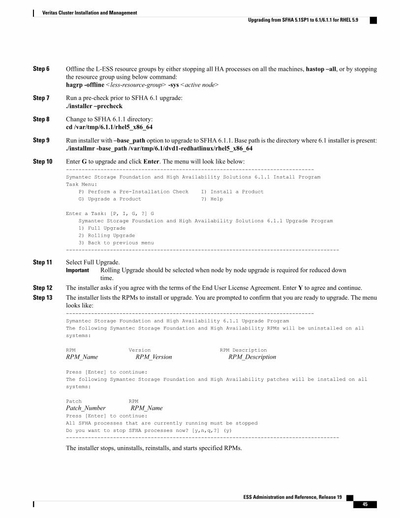
Step 6 Offline the L-ESS resource groups by either stopping all HA processes on all the machines, hastop –all, or by stoppingthe resource group using below command:hagrp -offline <less-resource-group> -sys <active node>
Step 7 Run a pre-check prior to SFHA 6.1 upgrade:./installer –precheck
Step 8 Change to SFHA 6.1.1 directory:cd /var/tmp/6.1.1/rhel5_x86_64
Step 9 Run installer with –base_path option to upgrade to SFHA 6.1.1. Base path is the directory where 6.1 installer is present:./installmr -base_path /var/tmp/6.1/dvd1-redhatlinux/rhel5_x86_64
Step 10 Enter G to upgrade and click Enter. The menu will look like below:-------------------------------------------------------------------------------Symantec Storage Foundation and High Availability Solutions 6.1.1 Install ProgramTask Menu:
P) Perform a Pre-Installation Check I) Install a ProductG) Upgrade a Product ?) Help
Enter a Task: [P, I, G, ?] GSymantec Storage Foundation and High Availability Solutions 6.1.1 Upgrade Program1) Full Upgrade2) Rolling Upgrade3) Back to previous menu
---------------------------------------------------------------------------------------
Step 11 Select Full Upgrade.Rolling Upgrade should be selected when node by node upgrade is required for reduced downtime.
Important
Step 12 The installer asks if you agree with the terms of the End User License Agreement. Enter Y to agree and continue.Step 13 The installer lists the RPMs to install or upgrade. You are prompted to confirm that you are ready to upgrade. The menu
looks like:-------------------------------------------------------------------------------Symantec Storage Foundation and High Availability 6.1.1 Upgrade ProgramThe following Symantec Storage Foundation and High Availability RPMs will be uninstalled on allsystems:
RPM Version RPM DescriptionRPM_Name RPM_Version RPM_Description
Press [Enter] to continue:The following Symantec Storage Foundation and High Availability patches will be installed on allsystems:
Patch RPMPatch_Number RPM_NamePress [Enter] to continue:All SFHA processes that are currently running must be stoppedDo you want to stop SFHA processes now? [y,n,q,?] (y)---------------------------------------------------------------------------------------
The installer stops, uninstalls, reinstalls, and starts specified RPMs.
ESS Administration and Reference, Release 19 45
Veritas Cluster Installation and ManagementUpgrading from SFHA 5.1SP1 to 6.1/6.1.1 for RHEL 5.9

Step 14 After successful VCS upgrade, online the Veritas resources on any single cluster node:hagrp -online <less-resource-group> -sys <active node>
ESS Administration and Reference, Release 1946
Veritas Cluster Installation and ManagementUpgrading from SFHA 5.1SP1 to 6.1/6.1.1 for RHEL 5.9

C H A P T E R 3ESS Installation and Configuration
This chapter describes how to install and configure the ESS application on the ESS Server.
It consists of the following topics:
• ESS Installation Modes, page 47
• Installing ESS Application in Stand-alone Mode, page 48
• Installing ESS Application in Cluster Mode, page 57
• Uninstalling ESS Application, page 67
• Configuring PSMON Threshold (Optional), page 68
ESS Installation ModesThis section provides information on the different modes available for the installation of ESS application.
The ESS application can be installed in one of the following modes:
• Stand-alone mode
• Cluster mode
In the cluster mode, ESS provides high availability and critical redundancy support to retrieve xDRs in caseof failure of any one of the systems. An ESS Veritas cluster comprises of two ESS systems, or nodes, thatwork together as a single, continuously available system to provide applications, system resources, and datato the ESS users. Each ESS node on the Veritas cluster is a fully functional, stand-alone system. However, ina Veritas clustered environment, the ESS nodes are connected by an interconnected network and work togetheras a single entity to provide increased data availability.
For more information on the Veritas cluster, refer to the Veritas Cluster Installation and Management chapter.
For stand-alone installation of ESS application, refer to the Installing ESS Application in Stand-alone Mode,on page 48 section. For cluster-based installation of ESS application, refer to the Installing ESS Applicationin Cluster Mode, on page 57 section.
ESS Administration and Reference, Release 19 47
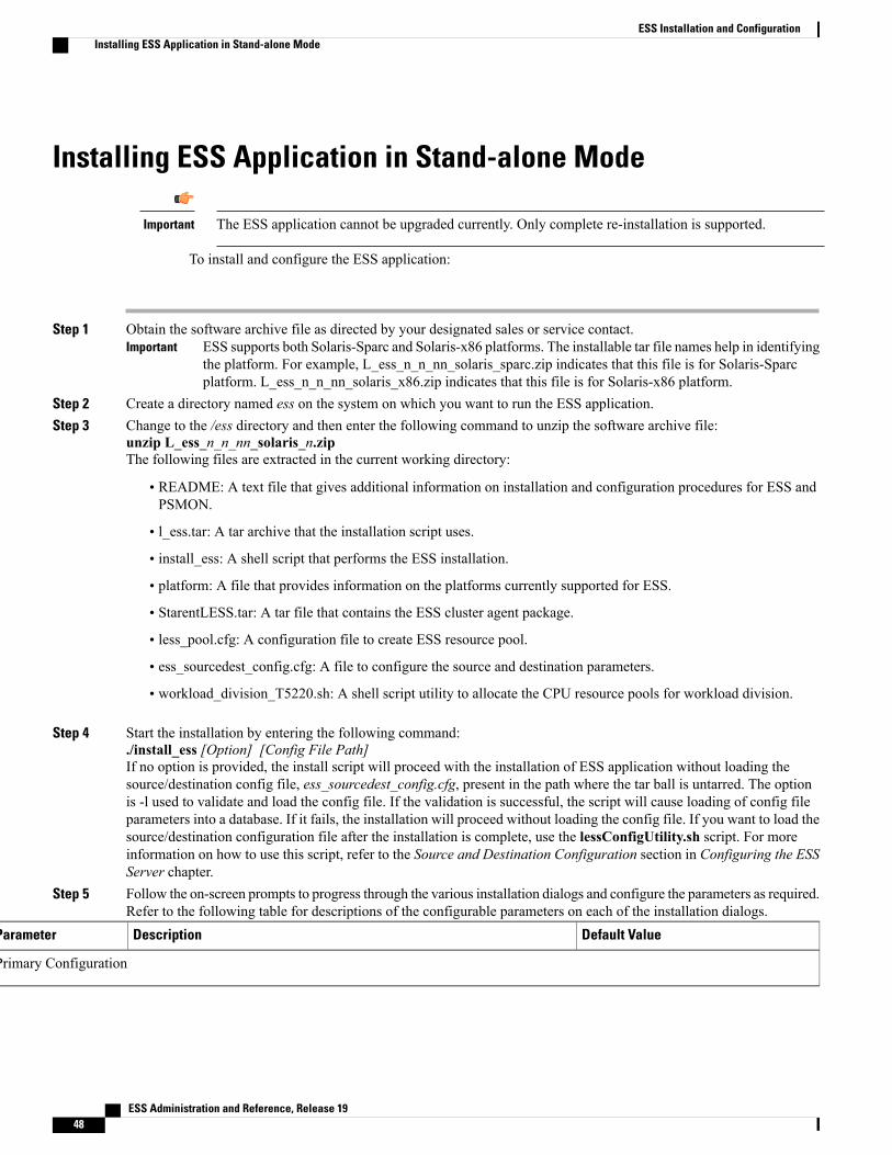
Installing ESS Application in Stand-alone Mode
The ESS application cannot be upgraded currently. Only complete re-installation is supported.Important
To install and configure the ESS application:
Step 1 Obtain the software archive file as directed by your designated sales or service contact.ESS supports both Solaris-Sparc and Solaris-x86 platforms. The installable tar file names help in identifyingthe platform. For example, L_ess_n_n_nn_solaris_sparc.zip indicates that this file is for Solaris-Sparcplatform. L_ess_n_n_nn_solaris_x86.zip indicates that this file is for Solaris-x86 platform.
Important
Step 2 Create a directory named ess on the system on which you want to run the ESS application.Step 3 Change to the /ess directory and then enter the following command to unzip the software archive file:
unzip L_ess_n_n_nn_solaris_n.zipThe following files are extracted in the current working directory:
• README: A text file that gives additional information on installation and configuration procedures for ESS andPSMON.
• l_ess.tar: A tar archive that the installation script uses.
• install_ess: A shell script that performs the ESS installation.
• platform: A file that provides information on the platforms currently supported for ESS.
• StarentLESS.tar: A tar file that contains the ESS cluster agent package.
• less_pool.cfg: A configuration file to create ESS resource pool.
• ess_sourcedest_config.cfg: A file to configure the source and destination parameters.
• workload_division_T5220.sh: A shell script utility to allocate the CPU resource pools for workload division.
Step 4 Start the installation by entering the following command:./install_ess [Option] [Config File Path]If no option is provided, the install script will proceed with the installation of ESS application without loading thesource/destination config file, ess_sourcedest_config.cfg, present in the path where the tar ball is untarred. The optionis -l used to validate and load the config file. If the validation is successful, the script will cause loading of config fileparameters into a database. If it fails, the installation will proceed without loading the config file. If you want to load thesource/destination configuration file after the installation is complete, use the lessConfigUtility.sh script. For moreinformation on how to use this script, refer to the Source and Destination Configuration section in Configuring the ESSServer chapter.
Step 5 Follow the on-screen prompts to progress through the various installation dialogs and configure the parameters as required.Refer to the following table for descriptions of the configurable parameters on each of the installation dialogs.
Default ValueDescriptionParameter
Primary Configuration
ESS Administration and Reference, Release 1948
ESS Installation and ConfigurationInstalling ESS Application in Stand-alone Mode

Default ValueDescriptionParameter
Current directory from where the ESSinstallation script is executed.
Type the directory path where you want the ESS to be installed. The defaultis the current directory.
ESS InstallationDirectory
IP address of the local machine whereESS is installed
Type the IP address of the local machine where the ESS application isinstalled.
Both IPv4 and IPv6 addresses can be configured. When configuring IPv6address, make sure that you are configuring global IPv6 address, not Linkscope address like 'fe80::8a5a:92ff:fe88:1536'.
This IP address will be used to lock a socket to avoid startingof similar ESS instances. In case of stand alone installation thisshould be machine's IP address and in case of cluster basedinstallation this should be Logical Host's IP address. Default iscurrent machine's IP address.
Important
IP Address for ESSinstallation
<less_install_dir>/ess/fetched_dataType the base directory path for the fetched data.Base Directory Pathfor Fetched Data
Stand-alone mode:<less_install_dir>/ess/log
Cluster mode:When the ESS installationis in shared path, the log files will beavailable at <shared_path>/LESS/log.
When the ESS installation is in local pathand the data files are on shared path, thelog files will be available at<shared_path>/LESS/lesslog_hostname.
Type the directory path for the log files.Log Directory Path
nUse this option to install init scripts for a standalone ESS installation. Thesescripts are required if you want to start the ESS application after a systemreboot.
Type (Y)es to create the init script named less in the /etc/init.d/ location.
Install init scripts [forstandalone]
SMTP Configuration
NullIf youwant ProcessMonitor (PSMON) alert messages automatically e-mailedto a specific person, type the host name or IP address of a valid SMTP server.Press ENTER for no SMTP server and e-mail recipient.
SMTP Server Name
NullType the e-mail address of the person who should receive the alert messages.Email-ID [To ]
Miscellaneous Configuration
ESS Administration and Reference, Release 19 49
ESS Installation and ConfigurationInstalling ESS Application in Stand-alone Mode
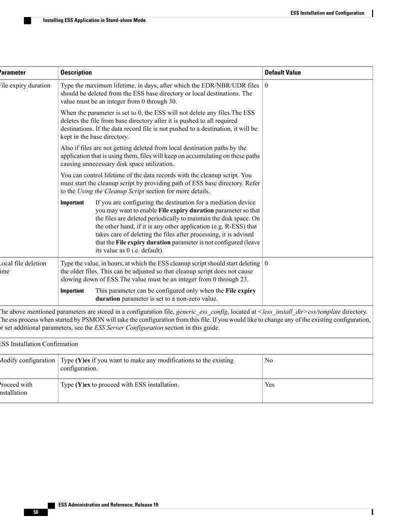
Default ValueDescriptionParameter
0Type the maximum lifetime, in days, after which the EDR/NBR/UDR filesshould be deleted from the ESS base directory or local destinations. Thevalue must be an integer from 0 through 30.
When the parameter is set to 0, the ESS will not delete any files.The ESSdeletes the file from base directory after it is pushed to all requireddestinations. If the data record file is not pushed to a destination, it will bekept in the base directory.
Also if files are not getting deleted from local destination paths by theapplication that is using them, files will keep on accumulating on these pathscausing unnecessary disk space utilization.
You can control lifetime of the data records with the cleanup script. Youmust start the cleanup script by providing path of ESS base directory. Referto the Using the Cleanup Script section for more details.
If you are configuring the destination for a mediation deviceyou may want to enable File expiry duration parameter so thatthe files are deleted periodically to maintain the disk space. Onthe other hand, if it is any other application (e.g. R-ESS) thattakes care of deleting the files after processing, it is advisedthat the File expiry duration parameter is not configured (leaveits value as 0 i.e. default).
Important
File expiry duration
0Type the value, in hours, at which the ESS cleanup script should start deletingthe older files. This can be adjusted so that cleanup script does not causeslowing down of ESS.The value must be an integer from 0 through 23.
This parameter can be configured only when the File expiryduration parameter is set to a non-zero value.
Important
Local file deletiontime
The above mentioned parameters are stored in a configuration file, generic_ess_config, located at <less_install_dir>ess/template directory.The ess process when started by PSMONwill take the configuration from this file. If you would like to change any of the existing configuration,or set additional parameters, see the ESS Server Configuration section in this guide.
ESS Installation Confirmation
NoType (Y)es if you want to make any modifications to the existingconfiguration.
Modify configuration
YesType (Y)es to proceed with ESS installation.Proceed withinstallation
ESS Administration and Reference, Release 1950
ESS Installation and ConfigurationInstalling ESS Application in Stand-alone Mode
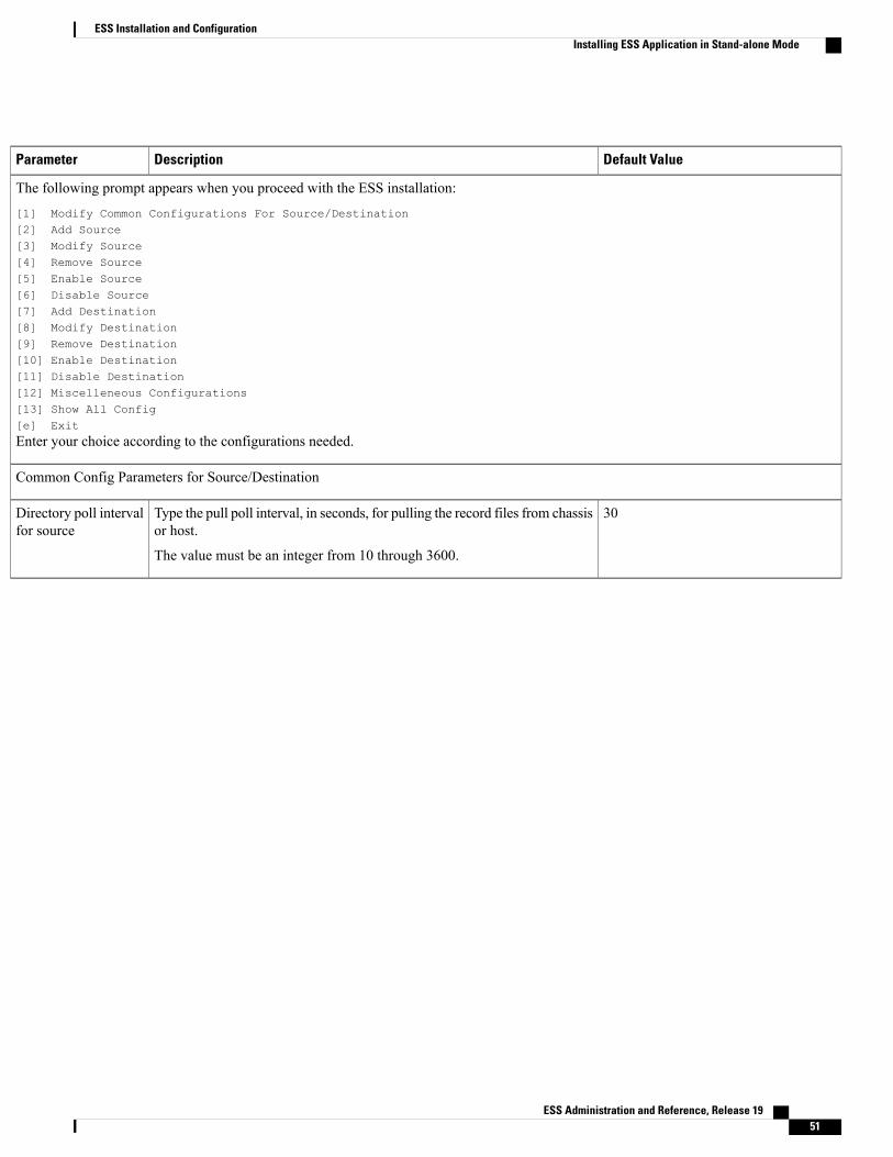
Default ValueDescriptionParameter
The following prompt appears when you proceed with the ESS installation:
[1] Modify Common Configurations For Source/Destination[2] Add Source[3] Modify Source[4] Remove Source[5] Enable Source[6] Disable Source[7] Add Destination[8] Modify Destination[9] Remove Destination[10] Enable Destination[11] Disable Destination[12] Miscelleneous Configurations[13] Show All Config[e] Exit
Enter your choice according to the configurations needed.
Common Config Parameters for Source/Destination
30Type the pull poll interval, in seconds, for pulling the record files from chassisor host.
The value must be an integer from 10 through 3600.
Directory poll intervalfor source
ESS Administration and Reference, Release 19 51
ESS Installation and ConfigurationInstalling ESS Application in Stand-alone Mode

Default ValueDescriptionParameter
1Select from the currently available file formats for xDR files.
• [1]FIELDSEP(_)_STR_RULEBASENAME_TIMESTAMP_RSTIND_SEQUENCENO(0,999999999)
• [2]FIELDSEP(_)_STR_RULEBASENAME_TIMESTAMP_RSTIND_SEQUENCENO(0,999999999)_PSCNO
• [3]FIELDSEP(_)_STR_RULEBASENAME_TIMESTAMP_SEQUENCENO(0,999999999)
• [4] FIELDSEP(_)_STR-RULEBASENAME_STR_TIMESTAMP
• [5] FIELDSEP(_)_STR_TIMESTAMP(MM_DD_YYYY+HH:MM:SS)_STR_STR(file)SEQUENCENO(1,4294967295).EXT
• [6] FIELDSEP(_)_STR_TIMESTAMP(MM_DD_YYYY+HH:MM:SS)_STR_STR(file)SEQUENCENO(1,4294967295)
• [7] FIELDSEP(_)_STR_TIMESTAMP(MM_DD_YYYY+HH:MM:SS)_STR_STR(file)SEQUENCENO(1,999999).EXT
• [8] FIELDSEP(_)_STR_STR_TIMESTAMP(YYYYMMDDHHMMSS).EXT
In ESS 14.0 and later releases:
• [9] STR
• [10] ACR_FILEFORMAT
In ESS 9.0 and earlier releases:
• [9] ACR_FILEFORMAT
Modification in file format requires restart ofESS.
Important
You can also customize your own format according to the file namingconvention.
File name format forsource
yType (Y)es to delete record files from source directory after fetching.
Type (N)o to keep record files at source directory even after fetching.Please set this configuration to (Y)eswhen cdr-multi-mode isenabled at ASR5x00. Otherwise, L-ESS might fail to identifyfresh files at source and may skip pulling of fresh files.
Important
Delete files fromsource
ESS Administration and Reference, Release 1952
ESS Installation and ConfigurationInstalling ESS Application in Stand-alone Mode

Default ValueDescriptionParameter
yType (Y)es to activate alarmwhen files are found missing while pulling themfrom chassis.
Type (N)o to deactivate alarm when files are found missing while pullingthem from chassis.
This feature is to be set to (Y)es only if file naming formatcontains sequence number.
Important
Please set this configuration to (N)o if cdr-multi-mode isenabled at ASR5x00 as L-ESS might fail to uniquely identifysequence of files and may not report the missing filesappropriately.
Important
This particular alarm generation can be enabled only if thedeletion of EDR or UDR files from remote host is enabled andthe SNMP support is enabled.
Important
Report missed filesfrom remote source
curr_Type the transient file prefix for source files. This is a customer specificunique text prefix to distinguish the incomplete files from final files.
Transient file prefixfor source
NullType the transfer file prefix for destination files. This is a customer specificunique text prefix to distinguish the incomplete files from final files.
Transfer file prefix fordestination
0If SNMP feature is enabled and the number of total files to be fetched fromsource directory is larger than this threshold number then alarm"starLESSThreshPendingFiles" will be raised.
Alarms will be raised even if the files to be pushed to destination directoryis exceeding the configured limit.
Clear alarm "starLESSThreshClearPendingFiles"will be raised when numberof total files to be fetched falls below this threshold. The threshold value, 0indicates do not enable this threshold. Maximum value for this threshold is1000 files.
Pending file threshold
1Type the threshold value, in hours, to avoid the unnecessary half cookedfiles being stored under chassis' base directory. If incomplete file older thanthis threshold is found, then ESS removes the file.The value must be aninteger from 1 through 24.
Half cooked filedetection threshold
22Type the port number used to create SFTP connection to remote host.Port
3This value is used to decide number of times ESS can try to set up connectionto remote host in case of connection failure.
Connection retrycount
60This is the time interval after which ESS should reconsider connecting toremote host in case connection creation has failed earlier even after retryingconfigured number of times.
Connection RetryFrequency
ESS Administration and Reference, Release 19 53
ESS Installation and ConfigurationInstalling ESS Application in Stand-alone Mode
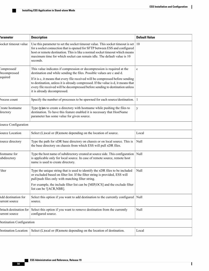
Default ValueDescriptionParameter
10Use this parameter to set the socket timeout value. This socket timeout is setfor a socket connection that is opened for SFTP between ESS and configuredhost or remote destination. This is like a normal socket timeout which meansmaximum time for which socket can remain idle. The default value is 10seconds.
Socket timeout value
cThis value indicates if compression or decompression is required at thedestination end while sending the files. Possible values are c and d.
If it is c, it means that every file received will be compressed before sendingto destination, unless it is already compressed. If the value is d, it means thatevery file received will be decompressed before sending to destination unlessit is already decompressed.
Compressed/Decompressedrequired
1Specify the number of processes to be spawned for each source/destination.Process count
yType (y)es to create a directory with hostname while pushing the files todestination. To have this feature enabled it is necessary that HostNameparameter has some value for given source.
Create hostnamedirectory
Source Configuration
LocalSelect (L)ocal or (R)emote depending on the location of source.Source Location
NullType the path for xDR base directory on chassis or on local source. This isthe base directory on chassis from which ESS will pull xDR files.
Source directory
NullType the host name of subdirectory created at source side. This configurationis applicable only for local source. In case of remote source, remote hostname is used to create directory.
Hostname forsubdirectory
NullType the unique string that is used to identify the xDR files to be includedor excluded based on filter list. If the filter string is provided, ESS willpull/push files only with matching filter string.
For example, the include filter list can be [MIP,OCS] and the exclude filterlist can be ![ACR,NBR].
Filter
NullSelect this option if you want to add destination to the currently configuredsource.
Add destination forcurrent source
NullSelect this option if you want to remove destination from the currentlyconfigured source.
Detach destination forcurrent source
Destination Configuration
LocalSelect (L)ocal or (R)emote depending on the location of destination.Destination Location
ESS Administration and Reference, Release 1954
ESS Installation and ConfigurationInstalling ESS Application in Stand-alone Mode

Default ValueDescriptionParameter
NullType the destination directory path at the destination side where xDR filesare to be stored. In cluster mode installation, this path should be shared path.
Destination directory
yType (Y)es if you want to create subdirectory with host name underdestination base path.
Create subdirectorywith hostname
yType (Y)es if you want to create subdirectory under the host name directoryif it exists.
Create subdir underhostname dir
dataType the name of the subdirectory being created.Subdirectory name
cType (Y)es if file is required in compressed format at the destination side.
If you type (Y)es, the file will be compressed (if it is not previouslycompressed) and then forwarded. If you type (N)o, the file will beuncompressed (if previously compressed) and then forwarded to destination.
How should files besent to destination?Compressed/Decompressed
NullType the unique string that is used to identify the xDR files to be includedor excluded based on filter list. If the filter string is provided, ESS willpull/push files only with matching filter string.
For example, the include filter list can be [MIP,OCS] and the exclude filterlist can be ![ACR,NBR].
Filter string
NullType the file prefix to be used while transferring the xDR files to thedestination.
File prefix whiletransfer
Miscellaneous Configuration
yTo enable the disk cleanup based on the disk utilization threshold level, type(Y)es. This causes the deletion of older files on disk crossing the thresholdof the Disk threshold 2 parameter until disk utilization drops below Diskthreshold 1.
Start disk clean upbased on threshold
80Type the first level threshold value, in percentage, for monitoring disk usage.If disk utilization goes beyond this threshold an alarm is raised indicatingthat the disk is overutilized. The value must be an integer from 1 through100.
Disk threshold 1
98Type the second level threshold value, in percentage, for monitoring diskusage. If disk utilization goes beyond this threshold an alarm is raisedindicating that the disk utilization has crossed the configured second levelthreshold. This threshold is specifically to notify that disk is now criticallylow. The value must be an integer from 1 through 100.
Disk threshold 2
YesType (Y)es to enable the SNMP trap notifications.Enable SNMP
ESS Administration and Reference, Release 19 55
ESS Installation and ConfigurationInstalling ESS Application in Stand-alone Mode
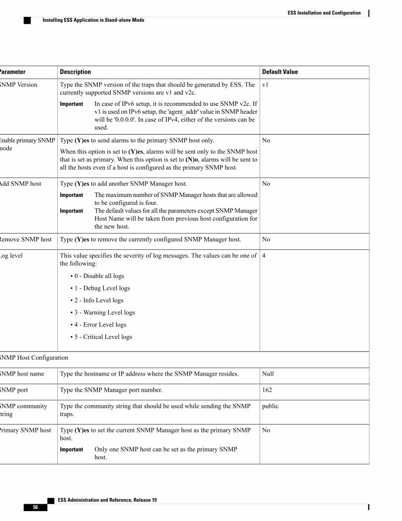
Default ValueDescriptionParameter
v1Type the SNMP version of the traps that should be generated by ESS. Thecurrently supported SNMP versions are v1 and v2c.
In case of IPv6 setup, it is recommended to use SNMP v2c. Ifv1 is used on IPv6 setup, the 'agent_addr' value in SNMP headerwill be '0.0.0.0'. In case of IPv4, either of the versions can beused.
Important
SNMP Version
NoType (Y)es to send alarms to the primary SNMP host only.
When this option is set to (Y)es, alarms will be sent only to the SNMP hostthat is set as primary. When this option is set to (N)o, alarms will be sent toall the hosts even if a host is configured as the primary SNMP host.
Enable primary SNMPmode
NoType (Y)es to add another SNMP Manager host.
Themaximumnumber of SNMPManager hosts that are allowedto be configured is four.
Important
The default values for all the parameters except SNMPManagerHost Name will be taken from previous host configuration forthe new host.
Important
Add SNMP host
NoType (Y)es to remove the currently configured SNMP Manager host.Remove SNMP host
4This value specifies the severity of log messages. The values can be one ofthe following:
• 0 - Disable all logs
• 1 - Debug Level logs
• 2 - Info Level logs
• 3 - Warning Level logs
• 4 - Error Level logs
• 5 - Critical Level logs
Log level
SNMP Host Configuration
NullType the hostname or IP address where the SNMP Manager resides.SNMP host name
162Type the SNMP Manager port number.SNMP port
publicType the community string that should be used while sending the SNMPtraps.
SNMP communitystring
NoType (Y)es to set the current SNMP Manager host as the primary SNMPhost.
Only one SNMP host can be set as the primary SNMPhost.
Important
Primary SNMP host
ESS Administration and Reference, Release 1956
ESS Installation and ConfigurationInstalling ESS Application in Stand-alone Mode
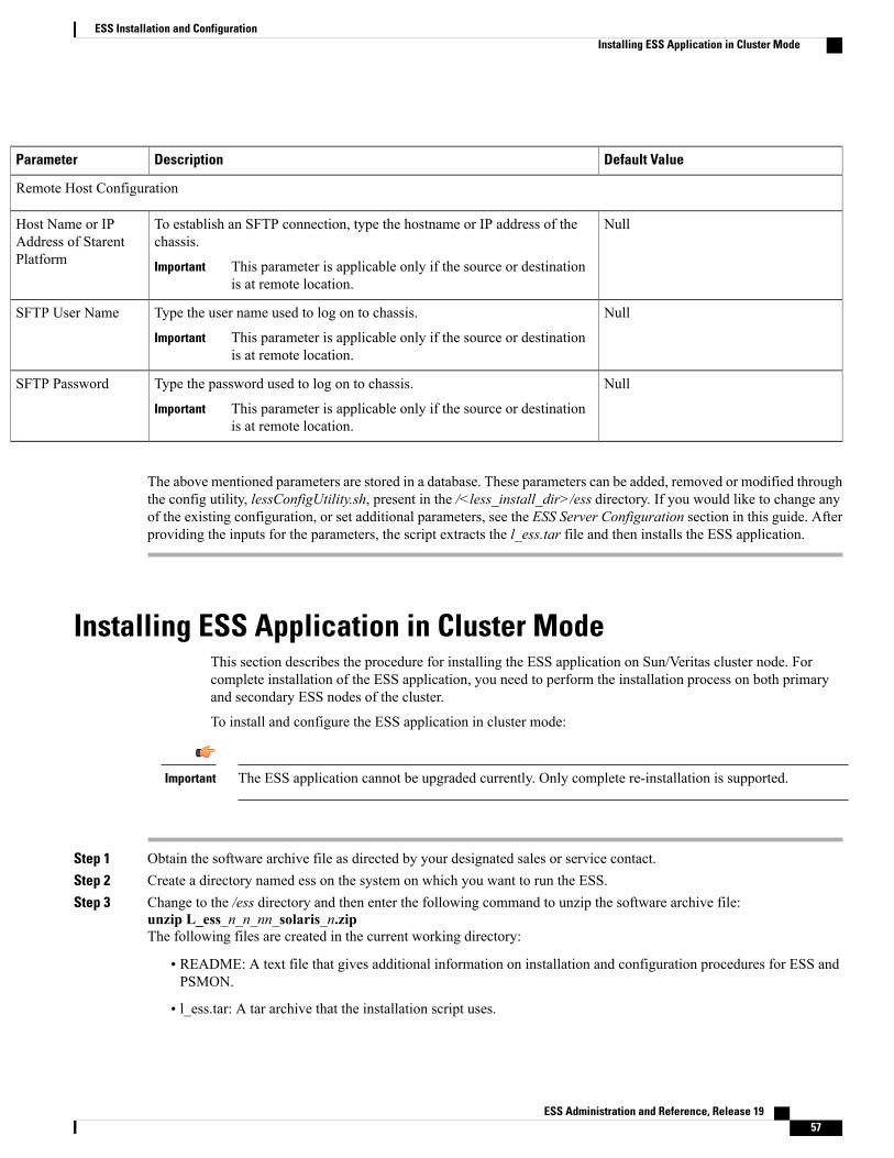
Default ValueDescriptionParameter
Remote Host Configuration
NullTo establish an SFTP connection, type the hostname or IP address of thechassis.
This parameter is applicable only if the source or destinationis at remote location.
Important
Host Name or IPAddress of StarentPlatform
NullType the user name used to log on to chassis.
This parameter is applicable only if the source or destinationis at remote location.
Important
SFTP User Name
NullType the password used to log on to chassis.
This parameter is applicable only if the source or destinationis at remote location.
Important
SFTP Password
The above mentioned parameters are stored in a database. These parameters can be added, removed or modified throughthe config utility, lessConfigUtility.sh, present in the /<less_install_dir>/ess directory. If you would like to change anyof the existing configuration, or set additional parameters, see the ESS Server Configuration section in this guide. Afterproviding the inputs for the parameters, the script extracts the l_ess.tar file and then installs the ESS application.
Installing ESS Application in Cluster ModeThis section describes the procedure for installing the ESS application on Sun/Veritas cluster node. Forcomplete installation of the ESS application, you need to perform the installation process on both primaryand secondary ESS nodes of the cluster.
To install and configure the ESS application in cluster mode:
The ESS application cannot be upgraded currently. Only complete re-installation is supported.Important
Step 1 Obtain the software archive file as directed by your designated sales or service contact.Step 2 Create a directory named ess on the system on which you want to run the ESS.Step 3 Change to the /ess directory and then enter the following command to unzip the software archive file:
unzip L_ess_n_n_nn_solaris_n.zipThe following files are created in the current working directory:
• README: A text file that gives additional information on installation and configuration procedures for ESS andPSMON.
• l_ess.tar: A tar archive that the installation script uses.
ESS Administration and Reference, Release 19 57
ESS Installation and ConfigurationInstalling ESS Application in Cluster Mode
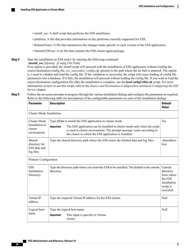
• install_ess: A shell script that performs the ESS installation.
• platform: A file that provides information on the platforms currently supported for ESS.
• ReleaseNotes: A file that summarizes the changes made specific to each version of the ESS application.
• StarentLESS.tar: A tar file that contains the ESS cluster agent package.
Step 4 Start the installation on ESS node1 by entering the following command:./install_ess [Option] [Config File Path]If no option is provided, the install script will proceed with the installation of ESS application without loading thesource/destination config file, ess_sourcedest_config.cfg, present in the path where the tar ball is untarred. The optionis -l used to validate and load the config file. If the validation is successful, the script will cause loading of config fileparameters into a database. If it fails, the installation will proceed without loading the config file. If you want to load thesource/destination configuration file after the installation is complete, use the lessConfigUtility.sh script. For moreinformation on how to use this script, refer to the Source and Destination Configuration section in Configuring the ESSServer chapter.
Step 5 Follow the on-screen prompts to progress through the various installation dialogs and configure the parameters as required.Refer to the following table for descriptions of the configurable parameters on each of the installation dialogs.
DefaultValue
DescriptionParameter
Cluster Mode Installation
YesType (Y)es to install the ESS application in cluster mode.
The ESS application can be installed in cluster mode only when the scriptis used in cluster environment. The prompt message varies according tothe cluster in which the ESS application is installed.
Important
Cluster ModeInstallation inclusterenvironment
/sharedless/less
Type the shared directory path where the ESS stores the fetched data and log files.Shareddirectory forESS data andlog files
Primary Configuration
Currentdirectoryfrom wherethe ESSinstallationscript isexecuted.
Type the directory path where you want the ESS to be installed. The default is the currentdirectory.
ESSInstallationDirectory
NullType the required Virtual IP address for the ESS cluster.Virtual IPaddress
NullType the logical host name.
This input is specific to Veritascluster.
Important
Logical hostname
ESS Administration and Reference, Release 1958
ESS Installation and ConfigurationInstalling ESS Application in Cluster Mode

DefaultValue
DescriptionParameter
SMTP Configuration
NullIf you want Process Monitor (PSMON) alert messages automatically e-mailed to aspecific person, type the host name or IP address of a valid SMTP server. PressENTERfor no SMTP server and e-mail recipient.
SMTP ServerName
NullType the e-mail address of the person who should receive the alert messages.Email-ID [To ]
Miscellaneous Configuration
0Type the maximum lifetime, in days, after which the EDR/NBR/UDR files should bedeleted from the ESS base directory or local destinations.The value must be an integerfrom 0 through 30.
When the parameter is set to 0, the ESS will not delete any files. The ESS deletes thefile from base directory after it is pushed to all required destinations. If the data recordfile is not pushed to a destination, it will be kept in the base directory.
Also if files are not getting deleted from local destination paths by the application thatis using them, files will keep on accumulating on these paths causing unnecessary diskspace utilization.
You can control lifetime of the data records with the cleanup script. You must start thecleanup script by providing path of ESS base directory. Refer to the Using the CleanupScript section for more details.
If you are configuring the destination for a mediation device youmaywantto enable File expiry duration parameter so that the files are deletedperiodically to maintain the disk space. On the other hand, if it is any otherapplication that takes care of deleting the files after processing, it is advisedthat the File expiry duration parameter is not configured (leave its valueas 0 i.e. default).
Important
File expiryduration
0Type the value, in hours, at which the ESS cleanup script should start deleting the olderfiles. This can be adjusted so that cleanup script does not cause slowing down of ESS.The value must be an integer from 0 through 23.
This parameter can be configured only when the File expiry durationparameter is set to a non-zero value.
Important
Local filedeletion time
The above mentioned parameters are stored in a configuration file, generic_ess_config, located at<less_install_dir>ess/template directory. The ess process when started by PSMON will take the configuration fromthis file. If you would like to change any of the existing configuration, or set additional parameters, see the ESS ServerConfiguration section in this guide.
ESS Installation Confirmation
NoType (Y)es if you want to make any modifications to the existing configuration.Modifyconfiguration
ESS Administration and Reference, Release 19 59
ESS Installation and ConfigurationInstalling ESS Application in Cluster Mode

DefaultValue
DescriptionParameter
YesType (Y)esto proceed with ESS installation.Proceed withinstallation
The following prompt appears when you proceed with the ESS installation:
[1] Modify Common Configurations For Source/Destination[2] Add Source[3] Modify Source[4] Remove Source[5] Enable Source[6] Disable Source[7] Add Destination[8] Modify Destination[9] Remove Destination[10] Enable Destination[11] Disable Destination[12] Miscelleneous Configurations[13] Show All Config[e] Exit
Enter your choice according to the configurations needed.
Common Config Parameters for Source/Destination
30Type the pull poll interval, in seconds, for pulling the record files from chassis or host.The value must be an integer from 10 through 3600.
Directory pollinterval forsource
ESS Administration and Reference, Release 1960
ESS Installation and ConfigurationInstalling ESS Application in Cluster Mode
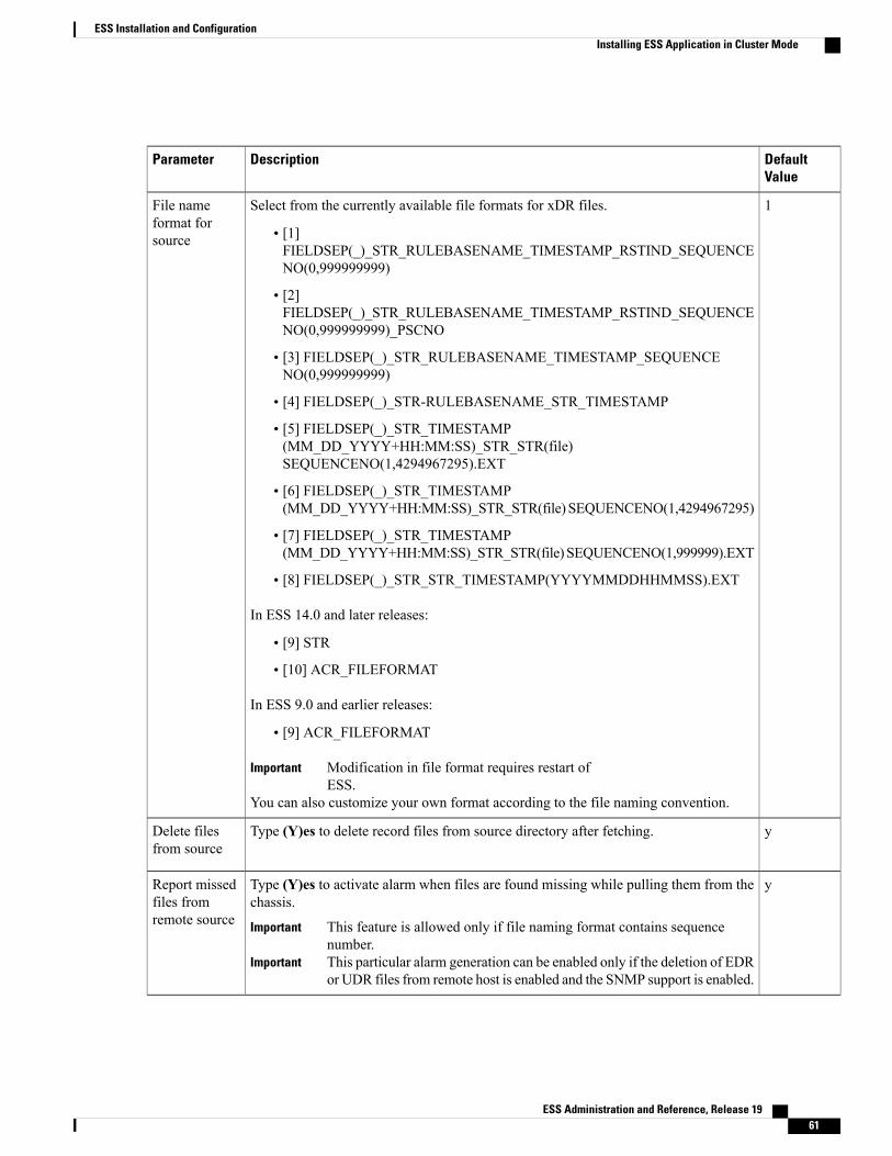
DefaultValue
DescriptionParameter
1Select from the currently available file formats for xDR files.
• [1]FIELDSEP(_)_STR_RULEBASENAME_TIMESTAMP_RSTIND_SEQUENCENO(0,999999999)
• [2]FIELDSEP(_)_STR_RULEBASENAME_TIMESTAMP_RSTIND_SEQUENCENO(0,999999999)_PSCNO
• [3] FIELDSEP(_)_STR_RULEBASENAME_TIMESTAMP_SEQUENCENO(0,999999999)
• [4] FIELDSEP(_)_STR-RULEBASENAME_STR_TIMESTAMP
• [5] FIELDSEP(_)_STR_TIMESTAMP(MM_DD_YYYY+HH:MM:SS)_STR_STR(file)SEQUENCENO(1,4294967295).EXT
• [6] FIELDSEP(_)_STR_TIMESTAMP(MM_DD_YYYY+HH:MM:SS)_STR_STR(file) SEQUENCENO(1,4294967295)
• [7] FIELDSEP(_)_STR_TIMESTAMP(MM_DD_YYYY+HH:MM:SS)_STR_STR(file) SEQUENCENO(1,999999).EXT
• [8] FIELDSEP(_)_STR_STR_TIMESTAMP(YYYYMMDDHHMMSS).EXT
In ESS 14.0 and later releases:
• [9] STR
• [10] ACR_FILEFORMAT
In ESS 9.0 and earlier releases:
• [9] ACR_FILEFORMAT
Modification in file format requires restart ofESS.
Important
You can also customize your own format according to the file naming convention.
File nameformat forsource
yType (Y)es to delete record files from source directory after fetching.Delete filesfrom source
yType (Y)es to activate alarm when files are found missing while pulling them from thechassis.
This feature is allowed only if file naming format contains sequencenumber.
Important
This particular alarm generation can be enabled only if the deletion of EDRor UDR files from remote host is enabled and the SNMP support is enabled.
Important
Report missedfiles fromremote source
ESS Administration and Reference, Release 19 61
ESS Installation and ConfigurationInstalling ESS Application in Cluster Mode

DefaultValue
DescriptionParameter
curr_Type the transient file prefix for source files. This is a customer specific unique textprefix to distinguish the incomplete files from final files.
Transient fileprefix forsource
curr_Type the transfer file prefix for destination files. This is a customer specific unique textprefix to distinguish the incomplete files from final files.
Transfer fileprefix fordestination
0If number of total files to be fetched from source directory is larger than this thresholdnumber then alarm "starLESSThreshPendingFiles" will be raised if SNMP feature isenabled.
Alarms will be raised even if the files to be pushed to destination directory is exceedingthe configured limit.
Clear alarm "starLESSThreshClearPendingFiles" will be raised when number of totalfiles to be fetched falls below this threshold. The threshold value, 0 indicates do notenable this threshold. Maximum value for this threshold is 1000 files.
Pending filethreshold
1Type the threshold value, in hours, to avoid the unnecessary half cooked files beingstored under chassis' base directory. If incomplete file older than this threshold is found,then ESS removes the file. The value must be an integer from 1 through 24.
Half cookedfile detectionthreshold
22Type the port number used to create SFTP connection to remote host.Port
3This value is used to decide number of times ESS can try to set up connection to remotehost in case of connection failure.
Connectionretry count
60This is the time interval after which ESS should reconsider connecting to remote hostin case connection creation has failed earlier even after retrying configured number oftimes.
ConnectionRetryFrequency
10Use this parameter to set the socket timeout value. This socket timeout is set for a socketconnection that is opened for SFTP between ESS and configured host or remotedestination. This is like a normal socket timeout which means maximum time for whichsocket can remain idle. The default value is 10 seconds.
Socket timeoutvalue
cThis value indicates if compression or decompression is required at the destination endwhile sending the files. Possible values are c and d.
If it is c, it means that every file received will be compressed before sending todestination, unless it is already compressed. If the value is d, it means that every filereceived will be decompressed before sending to destination unless it is alreadydecompressed.
Compressed/Decompressedrequired
1Specify the number of processes to be spawned for each source/destination.Process count
ESS Administration and Reference, Release 1962
ESS Installation and ConfigurationInstalling ESS Application in Cluster Mode
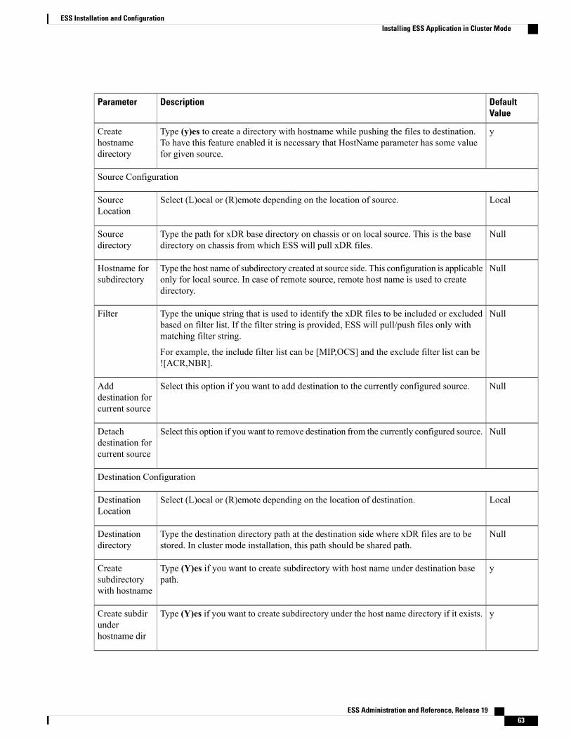
DefaultValue
DescriptionParameter
yType (y)es to create a directory with hostname while pushing the files to destination.To have this feature enabled it is necessary that HostName parameter has some valuefor given source.
Createhostnamedirectory
Source Configuration
LocalSelect (L)ocal or (R)emote depending on the location of source.SourceLocation
NullType the path for xDR base directory on chassis or on local source. This is the basedirectory on chassis from which ESS will pull xDR files.
Sourcedirectory
NullType the host name of subdirectory created at source side. This configuration is applicableonly for local source. In case of remote source, remote host name is used to createdirectory.
Hostname forsubdirectory
NullType the unique string that is used to identify the xDR files to be included or excludedbased on filter list. If the filter string is provided, ESS will pull/push files only withmatching filter string.
For example, the include filter list can be [MIP,OCS] and the exclude filter list can be![ACR,NBR].
Filter
NullSelect this option if you want to add destination to the currently configured source.Adddestination forcurrent source
NullSelect this option if you want to remove destination from the currently configured source.Detachdestination forcurrent source
Destination Configuration
LocalSelect (L)ocal or (R)emote depending on the location of destination.DestinationLocation
NullType the destination directory path at the destination side where xDR files are to bestored. In cluster mode installation, this path should be shared path.
Destinationdirectory
yType (Y)es if you want to create subdirectory with host name under destination basepath.
Createsubdirectorywith hostname
yType (Y)es if you want to create subdirectory under the host name directory if it exists.Create subdirunderhostname dir
ESS Administration and Reference, Release 19 63
ESS Installation and ConfigurationInstalling ESS Application in Cluster Mode
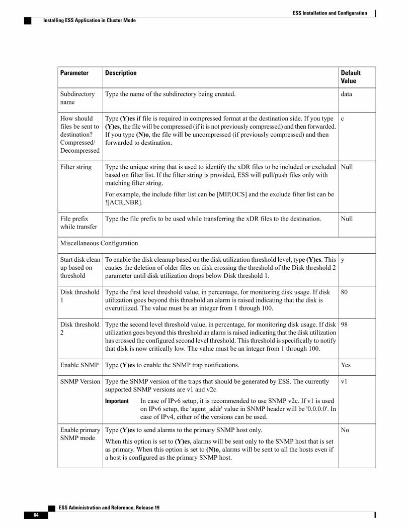
DefaultValue
DescriptionParameter
dataType the name of the subdirectory being created.Subdirectoryname
cType (Y)es if file is required in compressed format at the destination side. If you type(Y)es, the file will be compressed (if it is not previously compressed) and then forwarded.If you type (N)o, the file will be uncompressed (if previously compressed) and thenforwarded to destination.
How shouldfiles be sent todestination?Compressed/Decompressed
NullType the unique string that is used to identify the xDR files to be included or excludedbased on filter list. If the filter string is provided, ESS will pull/push files only withmatching filter string.
For example, the include filter list can be [MIP,OCS] and the exclude filter list can be![ACR,NBR].
Filter string
NullType the file prefix to be used while transferring the xDR files to the destination.File prefixwhile transfer
Miscellaneous Configuration
yTo enable the disk cleanup based on the disk utilization threshold level, type (Y)es. Thiscauses the deletion of older files on disk crossing the threshold of the Disk threshold 2parameter until disk utilization drops below Disk threshold 1.
Start disk cleanup based onthreshold
80Type the first level threshold value, in percentage, for monitoring disk usage. If diskutilization goes beyond this threshold an alarm is raised indicating that the disk isoverutilized. The value must be an integer from 1 through 100.
Disk threshold1
98Type the second level threshold value, in percentage, for monitoring disk usage. If diskutilization goes beyond this threshold an alarm is raised indicating that the disk utilizationhas crossed the configured second level threshold. This threshold is specifically to notifythat disk is now critically low. The value must be an integer from 1 through 100.
Disk threshold2
YesType (Y)es to enable the SNMP trap notifications.Enable SNMP
v1Type the SNMP version of the traps that should be generated by ESS. The currentlysupported SNMP versions are v1 and v2c.
In case of IPv6 setup, it is recommended to use SNMP v2c. If v1 is usedon IPv6 setup, the 'agent_addr' value in SNMP header will be '0.0.0.0'. Incase of IPv4, either of the versions can be used.
Important
SNMPVersion
NoType (Y)es to send alarms to the primary SNMP host only.
When this option is set to (Y)es, alarms will be sent only to the SNMP host that is setas primary. When this option is set to (N)o, alarms will be sent to all the hosts even ifa host is configured as the primary SNMP host.
Enable primarySNMP mode
ESS Administration and Reference, Release 1964
ESS Installation and ConfigurationInstalling ESS Application in Cluster Mode
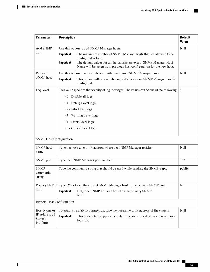
DefaultValue
DescriptionParameter
NullUse this option to add SNMP Manager hosts.
The maximum number of SNMP Manager hosts that are allowed to beconfigured is four.
Important
The default values for all the parameters except SNMP Manager HostName will be taken from previous host configuration for the new host.
Important
Add SNMPhost
NullUse this option to remove the currently configured SNMP Manager hosts.
This option will be available only if at least one SNMP Manager host isconfigured.
Important
RemoveSNMP host
4This value specifies the severity of log messages. The values can be one of the following:
• 0 - Disable all logs
• 1 - Debug Level logs
• 2 - Info Level logs
• 3 - Warning Level logs
• 4 - Error Level logs
• 5 - Critical Level logs
Log level
SNMP Host Configuration
NullType the hostname or IP address where the SNMP Manager resides.SNMP hostname
162Type the SNMP Manager port number.SNMP port
publicType the community string that should be used while sending the SNMP traps.SNMPcommunitystring
NoType (Y)es to set the current SNMP Manager host as the primary SNMP host.
Only one SNMP host can be set as the primary SNMPhost.
Important
Primary SNMPhost
Remote Host Configuration
NullTo establish an SFTP connection, type the hostname or IP address of the chassis.
This parameter is applicable only if the source or destination is at remotelocation.
Important
Host Name orIP Address ofStarentPlatform
ESS Administration and Reference, Release 19 65
ESS Installation and ConfigurationInstalling ESS Application in Cluster Mode

DefaultValue
DescriptionParameter
NullType the user name used to log on to chassis.
This parameter is applicable only if the source or destination is at remotelocation.
Important
SFTP UserName
NullType the password used to log on to chassis.
This parameter is applicable only if the source or destination is at remotelocation.
Important
SFTPPassword
The above mentioned parameters are stored in a database. These parameters can be added, removed or modified throughthe config utility. If you would like to change any of the existing configuration, or set additional parameters, see theESS Server Configuration section in this guide.
The ess process when started by PSMON will take the configuration from this file. If you would like to change any ofthe existing configuration, or set additional parameters, see the ESS Server Configuration section in this guide.
Step 6 After completion of ESS installation on node1, please perform switchover and then execute the ESS installation scripton node2.
Step 7 Type (y)es to continue the installation. The script displays the configuration settings for node1. If you want to makechanges to the existing configuration, modify the configuration as needed.
Step 8 If you do not want to make any changes to the configurations, type (y)es to continue the installation.After successful installation of ESS, verify the status of the ESS cluster resource group by entering the following command:For Veritas cluster:hastatusThe system displays the status of various cluster nodes, elements and resources. The status of the nodes must be onlineas displayed below:---------------- Cluster Nodes ----------------Node name Status--------- -------Cluster node: clustems2 OnlineCluster node: clustems1 Online------------------------------------------------------------ Cluster Transport Paths ---------
Endpoint Endpoint Status----------------- ------------------Transport path: clustems2:bge3 clustems1:bge3 Path onlineTransport path: clustems2:bge2 clustems1:bge2 Path online-------------------------------------------------------------------- Quorum Summary --Quorum votes possible: 3Quorum votes needed: 2Quorum votes present: 3
-- Quorum Votes by Node --Node Name Present Possible Status------------ ------- -------- -------Node votes: clustems2 1 1 OnlineNode votes: clustems1 1 1 Online-- Quorum Votes by Device --
ESS Administration and Reference, Release 1966
ESS Installation and ConfigurationInstalling ESS Application in Cluster Mode
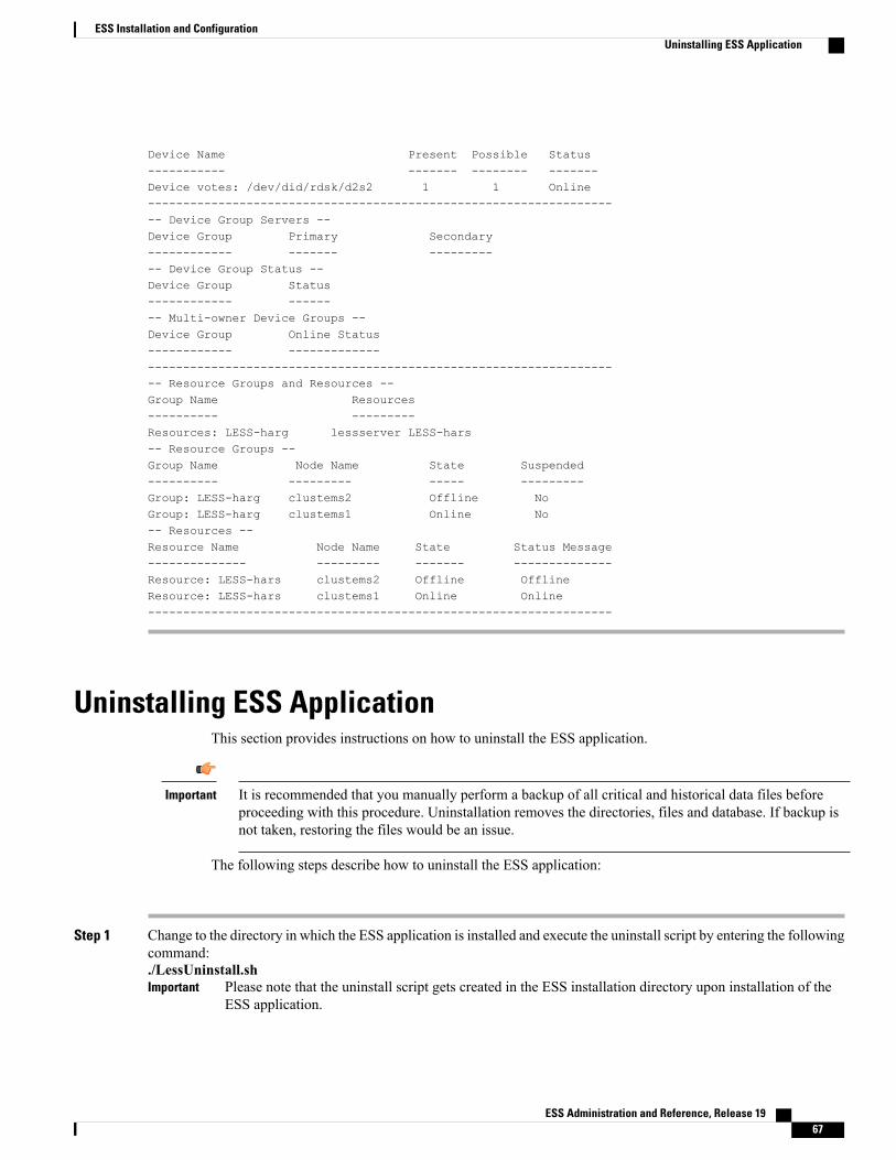
Device Name Present Possible Status----------- ------- -------- -------Device votes: /dev/did/rdsk/d2s2 1 1 Online-------------------------------------------------------------------- Device Group Servers --Device Group Primary Secondary------------ ------- ----------- Device Group Status --Device Group Status------------ -------- Multi-owner Device Groups --Device Group Online Status------------ --------------------------------------------------------------------------------- Resource Groups and Resources --Group Name Resources---------- ---------Resources: LESS-harg lessserver LESS-hars-- Resource Groups --Group Name Node Name State Suspended---------- --------- ----- ---------Group: LESS-harg clustems2 Offline NoGroup: LESS-harg clustems1 Online No-- Resources --Resource Name Node Name State Status Message-------------- --------- ------- --------------Resource: LESS-hars clustems2 Offline OfflineResource: LESS-hars clustems1 Online Online------------------------------------------------------------------
Uninstalling ESS ApplicationThis section provides instructions on how to uninstall the ESS application.
It is recommended that you manually perform a backup of all critical and historical data files beforeproceeding with this procedure. Uninstallation removes the directories, files and database. If backup isnot taken, restoring the files would be an issue.
Important
The following steps describe how to uninstall the ESS application:
Step 1 Change to the directory in which the ESS application is installed and execute the uninstall script by entering the followingcommand:./LessUninstall.sh
Please note that the uninstall script gets created in the ESS installation directory upon installation of theESS application.
Important
ESS Administration and Reference, Release 19 67
ESS Installation and ConfigurationUninstalling ESS Application

Step 2 Type (y)es to continue the uninstall.The script stops the ESS server, Process Monitor application, and the ESS processes.When uninstallation is finished, thesystem displays a message to indicate successful uninstallation and removal of the directories.
Step 3 Remove shared directories/process manually if not removed during uninstallation.
Configuring PSMON Threshold (Optional)PSMON is a Perl script that runs as a stand-alone program or as a fully functional background daemon.PSMON is capable of logging to a syslog and a log file with customizable e-mail notification facilities. Youcan define a set of rules in the psmon.cfg file. These rules describe what processes must always be runningon the system. PSMON scans the UNIX process table and uses the set of rules to restart any dead processes.
The following are the files/package used by PSMON:
• psmon: A perl script that handles monitoring processes and restarts them.
• ess/template/psmon.cfg: A configuration file for PSMON. Contains process information and otherinformation like e-mail id, smtp server, poll interval (or Frequency) and threshold parameters[MemoryUsed and SwapUsed, FinalDirPath and FinalDirThreshold].
• ess/3rdparty/perl/linux/perl5.8.7.tar: Perl 5.8.7 used by PSMON for LINUX.
• ess/3rdparty/perl/solaris/perl5.8.5.tar: Perl 5.8.5 used by PSMON for SOLARIS.
The PSMON utility monitors the following thresholds for the ESS application:
• The percentage of total memory used (Default: 50%)
• The percentage of swap space used (Default 50%)
• The final directory size in percentage of the file system used (Default 10%)
• The percentage of memory (Default: 10 %)
• The percentage of CPU resources used. (Default: 10%)
When these thresholds are crossed, an alert message is sent to the administrator/user at E-mail ID specifiedduring installation of ESS application. This alert message is also written to a log file, watchdog.log locatedin the <less_install_dir>/ess/log directory.
The watchdog.log file will be generated by PSMON.Important
To edit the PSMON configuration file for changing the threshold monitoring values of PSMON:
Step 1 Change to the directory where the psmon.cfg is present by entering the following command:cd <less_install_dir>/ess/template
ESS Administration and Reference, Release 1968
ESS Installation and ConfigurationConfiguring PSMON Threshold (Optional)

Step 2 Open the psmon.cfg in a standard text editor.Step 3 Find the following lines:
#THRESHOLDS for total memory used and total swap used in percentage (%).Default is 50 %MemoryUsed 50SwapUsed 50
Step 4 Change the values forMemoryUsed and SwapUsed to the desired percentages.The users are advisedNOT tomodify any parameters other thanMemoryUsed and SwapUsed.Important
Step 5 Save and close the file.Step 6 Stop and restart the PSMON process to implement these changes by using the procedures in Starting and Stopping ESS
and Using the Maintenance Utility sections.
ESS Administration and Reference, Release 19 69
ESS Installation and ConfigurationConfiguring PSMON Threshold (Optional)

ESS Administration and Reference, Release 1970
ESS Installation and ConfigurationConfiguring PSMON Threshold (Optional)

C H A P T E R 4Configuring the ESS Server
This chapter includes the following topics:
• ESS Server Configuration, page 71
• Source and Destination Configuration, page 73
• Starting and Stopping ESS, page 78
• Restarting LESS, page 78
ESS Server ConfigurationThis section provides information about the ESS configuration file parameters. ESS server configuration file,generic_ess_config, can be modified to fine-tune the operation of the application. This file is located in the<less_install_dir>/ess/template directory by default.
There are a few parameters that the installation script does not prompt for. These are available in thegeneric_ess_config file. The following table lists the ESS server configuration parameters and the correspondingdescriptions.
Any change in the generic_ess_config file requires ESS server restart.Important
Table 1: ESS Server Configuration Parameters
Default ValueDescriptionParameter
ASR 5x00 Parameters
0This specifies the time period (in days) for which files can bestored locally in ESS.
essdellocalrecordsexpirytime
ESS Administration and Reference, Release 19 71

Default ValueDescriptionParameter
0This specifies the time period (in hours) at which ESS shouldstart deleting local files stored in final directory depending onthe expiry time configured. This value must be an integer from0 through 23.
essdellocalrecordsstarttime
<less_install_dir>/ess/fetched_data
This specifies the ESS specific base directory path.essbasedirectorypath
Miscellaneous Parameters
<less_install_dir>/ ess/log
This specifies the directory path where ESS stores the ESSlogs.
logPath
NoIf this flag is enabled, ESS pull instance on start/restart emptiesthe file containing the entry of the last xDR file fetched fromthe chassis.
The ESS assumes that this is a fresh start and will refetch allthe files from chassis if ESS is configured not to delete filesfrom chassis. This parameter is also used to reset theinformation maintained for identifying missing files.
If this flag is set, each time when ESS instance restarts ESSwill also ignore the past information about missing fileidentification and the file contents will be reset.
resetfilecontent
60ESS uses this configurable to test whether ESS on startup isreferring to old information about missing files. The configuredvalue indicates the maximum allowed difference between thecurrent time stamp and the timestamp at which information foridentifying missing files was written.
If the difference exceeds, ESS will assume fresh restart andwill restart identifying missing files ignoring previousinformation.
Minimum value allowed is 30 minutes and maximum allowedis 1440 minutes (24 hours). Default is 60 minutes.
maxinfotimestampdiff
N/AThis specifies the IP address that is used by ESS to create TCPsocket. In case of stand alone installation this should be themachine's IP address and in case of cluster based installationthis should be Logical Host's IP address. Default is currentmachine's IP address.
In case of IPv6 address, configure global scopeIP address, and not Link scope address like'fe80::8a5a:92ff:fe88:1536'.
Important
ServerIpAddress
ESS Administration and Reference, Release 1972
Configuring the ESS ServerESS Server Configuration

Default ValueDescriptionParameter
22222This port is used when creating TCP sockets to avoid startingof similar ESS instances on the same ESSmachine. The defaultvalue for this parameter is 22222. The limit is within 1025 to65535.
Do not change this port unless it is absolutelyrequired.
Important
ServerPort
Source and Destination ConfigurationThis section provides information about the source and destination configuration file parameters. The sourceand destination configuration file, ess_sourcedest_config, is located in the directory where the installable tarfile is extracted.
This config file can be loaded to a database using a config utility called lessConfigUtility.sh. This script canalso be used to add/remove/modify the configuration for particular source/destination, and other miscellaneousconfigurations like changing config parameters and adding/removing/modifying SNMP host.
The config file based configuration is provided to load source/destination config in bulk. Please note thefollowing points:
• Common configuration parameters will be applied to all source/destination configured through the configfile.
• If any parameter is changed from particular source/destination configuration block then changed valuewill be applied to source/destination instead of the value from common config.
• Destination can be configured from "common local destination block" / "common remote destinationblock" / "destination block per source".
• If the source block is having corresponding destination configuration then same configuration will beused for destination.
• If the source does not have corresponding destination configuration then configuration from "commonlocal destination block"/ "common remote destination block" will be used depending on the location (R- Remote / L - Local) value.
• Source-Destination mapping
◦Source Path1,Filter1 mapped to Destination Path1,subdirectory1,Filter1
◦Source Path2,Filter2 mapped to Destination Path2,subdirectory2,Filter2
◦Source Path5,Filter5 mapped to Destination Path5,subdirectory5,Filter5
To load the source/destination config file after the ESS installation is complete:
1 Modify the source/destination config file template as per the requirements.
2 Use the config utility present in the <less_install_dir>/ess directory to validate and load the config file.
./lessConfigUtility.sh [Options] [Config File Path]
The [Config File Path] is the path where the config file is present.
ESS Administration and Reference, Release 19 73
Configuring the ESS ServerSource and Destination Configuration
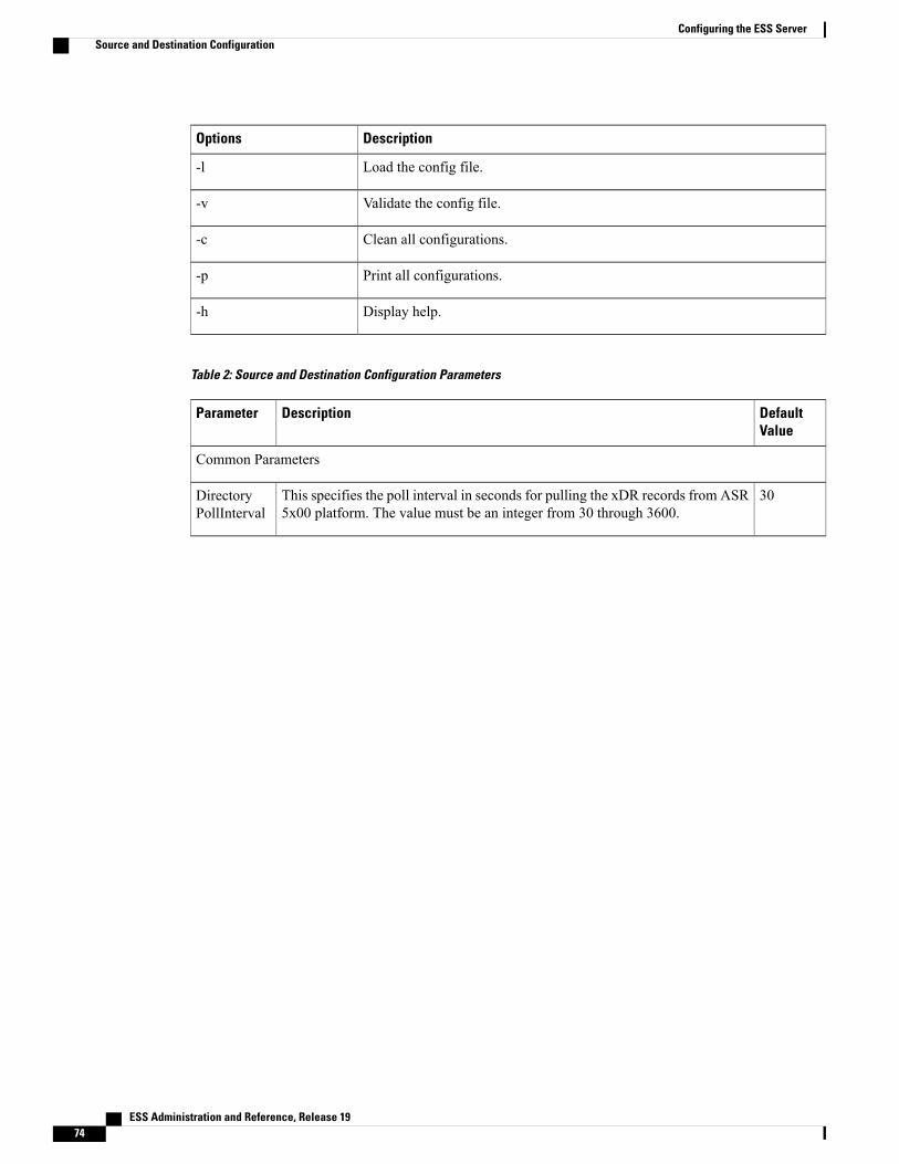
DescriptionOptions
Load the config file.-l
Validate the config file.-v
Clean all configurations.-c
Print all configurations.-p
Display help.-h
Table 2: Source and Destination Configuration Parameters
DefaultValue
DescriptionParameter
Common Parameters
30This specifies the poll interval in seconds for pulling the xDR records from ASR5x00 platform. The value must be an integer from 30 through 3600.
DirectoryPollInterval
ESS Administration and Reference, Release 1974
Configuring the ESS ServerSource and Destination Configuration

DefaultValue
DescriptionParameter
1This specifies the file format for xDR file naming convention.
• [1]FIELDSEP(_)_STR_RULEBASENAME_TIMESTAMP_RSTIND_SEQUENCENO(0,999999999)
• [2]FIELDSEP(_)_STR_RULEBASENAME_TIMESTAMP_RSTIND_SEQUENCENO(0,999999999)_PSCNO
• [3]FIELDSEP(_)_STR_RULEBASENAME_TIMESTAMP_SEQUENCENO(0,999999999)
• [4] FIELDSEP(_)_STR-RULEBASENAME_STR_TIMESTAMP
• [5] FIELDSEP(_)_STR_TIMESTAMP(MM_DD_YYYY+HH:MM:SS)_STR_STR(file)SEQUENCENO(1,4294967295).EXT
• [6] FIELDSEP(_)_STR_TIMESTAMP(MM_DD_YYYY+HH:MM:SS)_STR_STR(file)SEQUENCENO(1,4294967295)
• [7] FIELDSEP(_)_STR_TIMESTAMP(MM_DD_YYYY+HH:MM:SS)_STR_STR(file)SEQUENCENO(1,999999).EXT
• [8]FIELDSEP(_)_STR_STR_TIMESTAMP(YYYYMMDDHHMMSS).EXT
In ESS 14.0 and later releases:
• [9] STR
• [10] ACR_FILEFORMAT
In ESS 9.0 and earlier releases:
• [9] ACR_FILEFORMAT
Modification in file format requires restart ofESS.
Important
You can also customize your own format according to the file naming convention.
fileformat
yIf this flag is enabled this will cause deleting data records from the source directoryafter fetching. The possible values are:
• y – enable
• n – disable
DeleteFilesFrom Source
ESS Administration and Reference, Release 19 75
Configuring the ESS ServerSource and Destination Configuration
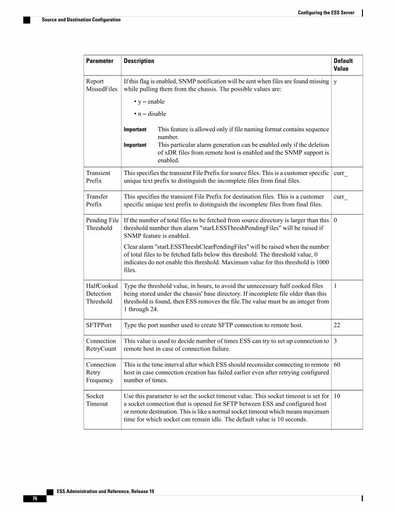
DefaultValue
DescriptionParameter
yIf this flag is enabled, SNMP notification will be sent when files are foundmissingwhile pulling them from the chassis. The possible values are:
• y – enable
• n – disable
This feature is allowed only if file naming format contains sequencenumber.
Important
This particular alarm generation can be enabled only if the deletionof xDR files from remote host is enabled and the SNMP support isenabled.
Important
ReportMissedFiles
curr_This specifies the transient File Prefix for source files. This is a customer specificunique text prefix to distinguish the incomplete files from final files.
TransientPrefix
curr_This specifies the transient File Prefix for destination files. This is a customerspecific unique text prefix to distinguish the incomplete files from final files.
TransferPrefix
0If the number of total files to be fetched from source directory is larger than thisthreshold number then alarm "starLESSThreshPendingFiles" will be raised ifSNMP feature is enabled.
Clear alarm "starLESSThreshClearPendingFiles" will be raised when the numberof total files to be fetched falls below this threshold. The threshold value, 0indicates do not enable this threshold. Maximum value for this threshold is 1000files.
Pending FileThreshold
1Type the threshold value, in hours, to avoid the unnecessary half cooked filesbeing stored under the chassis' base directory. If incomplete file older than thisthreshold is found, then ESS removes the file.The value must be an integer from1 through 24.
HalfCookedDetectionThreshold
22Type the port number used to create SFTP connection to remote host.SFTPPort
3This value is used to decide number of times ESS can try to set up connection toremote host in case of connection failure.
ConnectionRetryCount
60This is the time interval after which ESS should reconsider connecting to remotehost in case connection creation has failed earlier even after retrying configurednumber of times.
ConnectionRetryFrequency
10Use this parameter to set the socket timeout value. This socket timeout is set fora socket connection that is opened for SFTP between ESS and configured hostor remote destination. This is like a normal socket timeout whichmeansmaximumtime for which socket can remain idle. The default value is 10 seconds.
SocketTimeout
ESS Administration and Reference, Release 1976
Configuring the ESS ServerSource and Destination Configuration

DefaultValue
DescriptionParameter
cThis value indicates if compression or decompression is required at the destinationend while sending the files. Possible values are c and d. If it is c, it means thatevery file received will be compressed before sending to destination, unless it isalready compressed. If the value is d, it means that every file received will bedecompressed before sending to destination unless it is already decompressed.
CompressionDecompressionAtDestination
1Specify the number of processes to be spawned for each source/destination.ProcessCount
yType (y)es to create a directory with hostname while pushing the files todestination. To have this feature enabled it is necessary thatHostName parameterhas some value for given source.
CreateHostNameDir
Common Local Destination Parameters
NullType the path for xDR base directory on chassis or on local source. This is thebase directory on the chassis from which ESS will pull xDR files.
Path
Type the name of the subdirectory being created under destination base path.Subdirectory
NullType the unique string that is used to identify the xDR files. If filter string isprovided, ESS will pull files only with matching filter string.
Filter is the string based on which the files are to be moved to appropriatedirectory. If a filter is specified for certain type of record, it is must to specifyfor other types of records as well. Otherwise, files for that record type will notbe moved to any destination.
Filter
Common Remote Destination Parameters
NullType the host name for the remote destination.HostName
NullType the host user name for the remote destination.RemoteHostUserName
NullType the password used for the remote destination.RemoteHostPassword
NullType the path for xDR base directory on chassis or on local source. This is thebase directory on the chassis from which ESS will pull xDR files.
Path
Type the name of the subdirectory being created under destination base path.Subdirectory
ESS Administration and Reference, Release 19 77
Configuring the ESS ServerSource and Destination Configuration
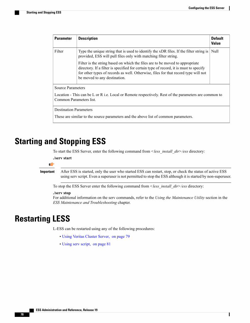
DefaultValue
DescriptionParameter
NullType the unique string that is used to identify the xDR files. If the filter string isprovided, ESS will pull files only with matching filter string.
Filter is the string based on which the files are to be moved to appropriatedirectory. If a filter is specified for certain type of record, it is must to specifyfor other types of records as well. Otherwise, files for that record type will notbe moved to any destination.
Filter
Source Parameters
Location - This can be L or R i.e. Local or Remote respectively. Rest of the parameters are common toCommon Parameters list.
Destination Parameters
These are similar to the source parameters and the above list of common parameters.
Starting and Stopping ESSTo start the ESS Server, enter the following command from <less_install_dir>/ess directory:./serv start
After ESS is started, only the user who started ESS can restart, stop, or check the status of active ESSusing serv script. Even a superuser is not permitted to stop the ESS although it is started by non-superuser.
Important
To stop the ESS Server enter the following command from <less_install_dir>/ess directory:./serv stopFor additional information on the serv commands, refer to the Using the Maintenance Utility section in theESS Maintenance and Troubleshooting chapter.
Restarting LESSL-ESS can be restarted using any of the following procedures:
• Using Veritas Cluster Server, on page 79
• Using serv script, on page 81
ESS Administration and Reference, Release 1978
Configuring the ESS ServerStarting and Stopping ESS

Using Veritas Cluster ServerThe following procedure is the preferred way of restarting the L-ESS when it is installed with Veritas:
Step 1 Find the Veritas Group configured for LESS.If L-ESS installation guide is followed, the configured Veritas Group should be less-ha. Otherwise, use the followingcommand:rootpnclustless1 hagrp -listless-ha pnclustless1less-ha pnclustless2
Step 2 Find the resource configured for L-ESS Application.Usually, it is configured to be less-app. It can be confirmed using the following command:rootpnclustless1 hagrp -resources less-haless-apps-dgless-apps-volless-apps-mntless-appless-nicless-ip
Step 3 Check the current status of Veritas.rootpnclustless1 hastatusattempting to connect ....attempting to connect ....connected
group resource system message--------------- -------------------- -------------------- --------------------
pnclustless1 RUNNINGpnclustless2 RUNNING
less-ha pnclustless1 OFFLINEless-ha pnclustless2 ONLINE-------------------------------------------------------------------------
less-apps-dg pnclustless1 OFFLINEless-apps-dg pnclustless2 ONLINEless-apps-vol pnclustless1 OFFLINEless-apps-vol pnclustless2 ONLINEless-apps-mnt pnclustless1 OFFLINE
-------------------------------------------------------------------------less-apps-mnt pnclustless2 ONLINEless-app pnclustless1 OFFLINEless-app pnclustless2 ONLINEless-nic pnclustless1 ONLINEless-nic pnclustless2 ONLINE
-------------------------------------------------------------------------less-ip pnclustless1 OFFLINEless-ip pnclustless2 ONLINE
Currently, less-app is online on pnclustless2Step 4 Bring this resource, less-app, offline by using the following command:
rootpnclustless1 hares -offline less-app -sys pnclustless2
Now, the status of Veritas will change. The less-app will be offline on both the nodes.rootpnclustless1 hastatusattempting to connect....
ESS Administration and Reference, Release 19 79
Configuring the ESS ServerUsing Veritas Cluster Server
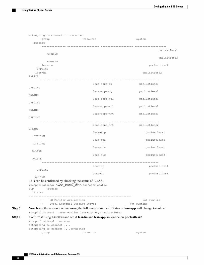
attempting to connect....connectedgroup resource system
message--------------- -------------------- -------------------- --------------------
pnclustless1RUNNING
pnclustless2RUNNING
less-ha pnclustless1OFFLINEless-ha pnclustless2
PARTIAL-------------------------------------------------------------------------
less-apps-dg pnclustless1OFFLINE
less-apps-dg pnclustless2ONLINE
less-apps-vol pnclustless1OFFLINE
less-apps-vol pnclustless2ONLINE
less-apps-mnt pnclustless1OFFLINE
-------------------------------------------------------------------------less-apps-mnt pnclustless2
ONLINEless-app pnclustless1
OFFLINEless-app pnclustless2
OFFLINEless-nic pnclustless1
ONLINEless-nic pnclustless2
ONLINE-------------------------------------------------------------------------
less-ip pnclustless1OFFLINE
less-ip pnclustless2ONLINE
This can be confirmed by checking the status of L-ESS:rootpnclustless2 <less_install_dir>/ess/serv statusPID Process
Status----------------------------------------------------------------
- PS Monitor Application Not running- Local External Storage Server Not running
Step 5 Now bring the resource online using the following command. Status of less-app will change to online.rootpnclustless1 hares -online less-app -sys pnclustless2
Step 6 Confirm it using hastatus and see if less-ha and less-app are online on pnclustless2.rootpnclustless1 hastatusattempting to connect ....attempting to connect ....connected
group resource system
ESS Administration and Reference, Release 1980
Configuring the ESS ServerUsing Veritas Cluster Server
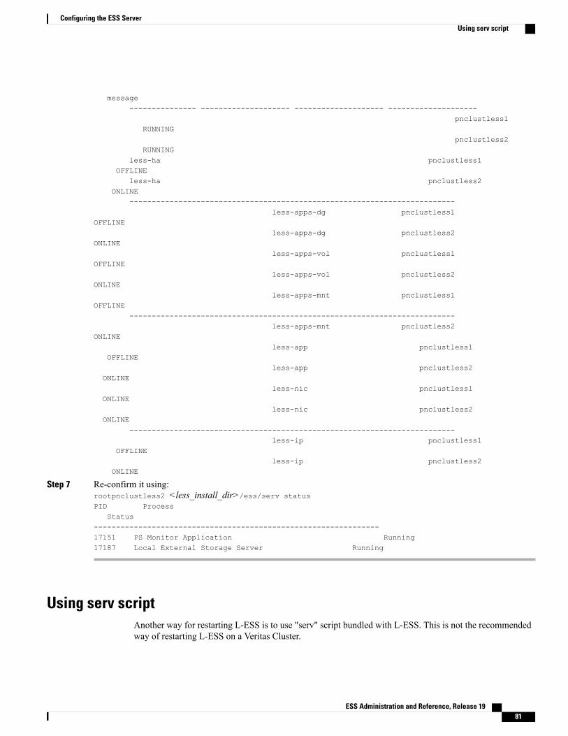
message--------------- -------------------- -------------------- --------------------
pnclustless1RUNNING
pnclustless2RUNNING
less-ha pnclustless1OFFLINE
less-ha pnclustless2ONLINE
-------------------------------------------------------------------------less-apps-dg pnclustless1
OFFLINEless-apps-dg pnclustless2
ONLINEless-apps-vol pnclustless1
OFFLINEless-apps-vol pnclustless2
ONLINEless-apps-mnt pnclustless1
OFFLINE-------------------------------------------------------------------------
less-apps-mnt pnclustless2ONLINE
less-app pnclustless1OFFLINE
less-app pnclustless2ONLINE
less-nic pnclustless1ONLINE
less-nic pnclustless2ONLINE
-------------------------------------------------------------------------less-ip pnclustless1
OFFLINEless-ip pnclustless2
ONLINE
Step 7 Re-confirm it using:rootpnclustless2 <less_install_dir>/ess/serv statusPID Process
Status----------------------------------------------------------------17151 PS Monitor Application Running17187 Local External Storage Server Running
Using serv scriptAnother way for restarting L-ESS is to use "serv" script bundled with L-ESS. This is not the recommendedway of restarting L-ESS on a Veritas Cluster.
ESS Administration and Reference, Release 19 81
Configuring the ESS ServerUsing serv script

It should only be used in a single node installation. Using this on a cluster installation may lead to nodeswitchover and may show a node to be faulted. However, it will not cause any loss of billing files.
Important
Enter the following commands from <less_install_dir>/ess directory:
Step 1 Check the current status of L-ESS.rootpnclustless2 ./serv statusPID Process
Status----------------------------------------------------------------17780 PS Monitor Application Running17812 Local External Storage Server Running
Step 2 Stop L-ESS.rootpnclustless2 ./serv stopStopping L-ESS. Please wait...Stopping PS Monitor Application...Stopping Local External Storage Server...Checking if all L-ESS processes have been stopped...Some L-ESS processes are still running.Checking if all L-ESS processes have been stopped...Some L-ESS processes are still running.Checking if all L-ESS processes have been stopped...Some L-ESS processes are still running.Checking if all L-ESS processes have been stopped...Local External Storage Server is stopped.
Step 3 Start L-ESSrootpnclustless2 ./serv start
Please Wait ...Starting L-ESS. Please wait...checking if L-ESS is started succesfully...checking if L-ESS is started succesfully...Local ESS Storage Server started.
Capturing status, please wait for a while...
=============================================================0 18345 12:32:23 TS 59 00:01
/export/home/LESS-HJ/less/less/ess/3rdparty/python/solaris//bin/python /export/ 10 18359 12:32:23 TS 59 00:00
/export/home/LESS-HJ/less/less/ess/3rdparty/python/solaris//bin/python /export/ 183450 18338 12:32:20 TS 59 00:00
/export/home/LESS-HJ/less/less/ess/3rdparty/perl/solaris//bin/perl -w /export/h 1=============================================================
Step 4 If there is a problem in stopping, use the following command to restart the server.rootpnclustless2 ./serv forcestartRestarting L-ESS. Please wait...Trying to stop already running L-ESS...Stopping PS Monitor Application...
ESS Administration and Reference, Release 1982
Configuring the ESS ServerUsing serv script
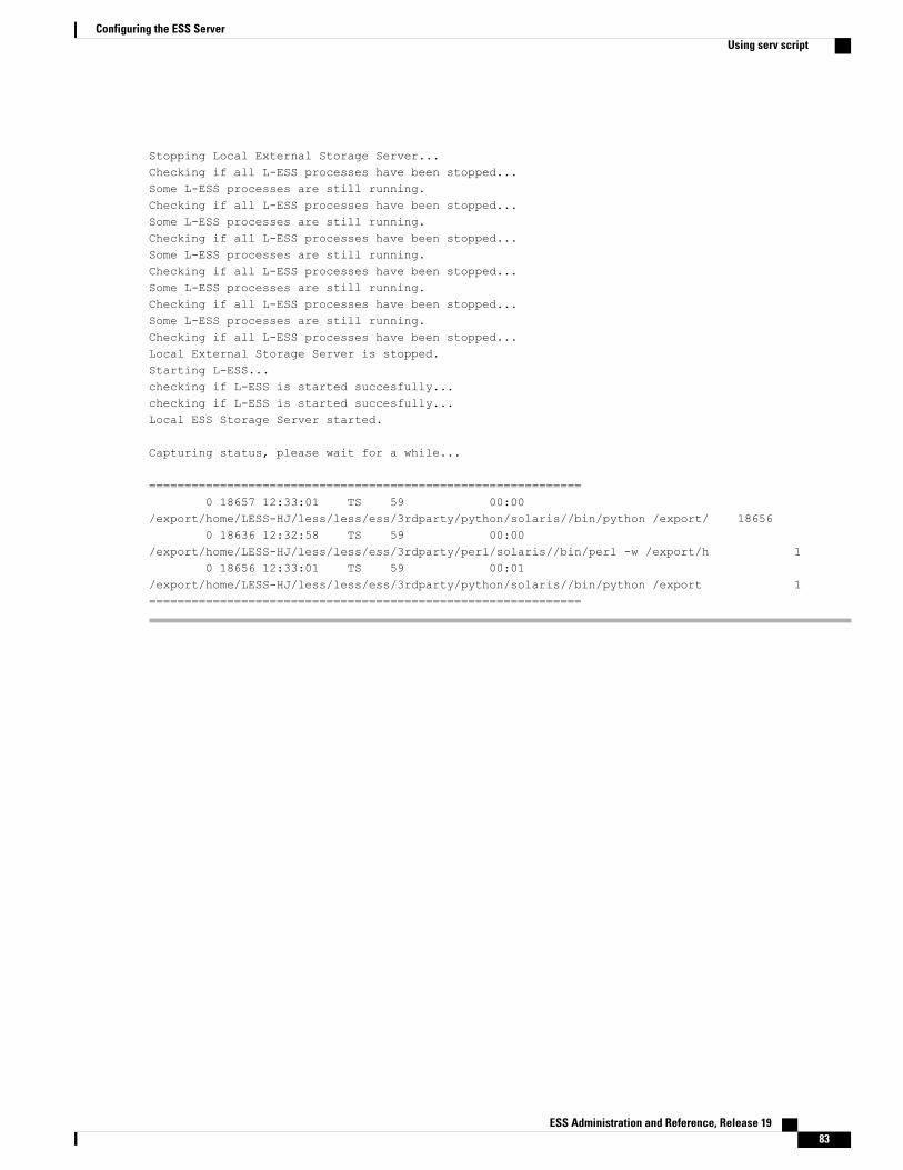
Stopping Local External Storage Server...Checking if all L-ESS processes have been stopped...Some L-ESS processes are still running.Checking if all L-ESS processes have been stopped...Some L-ESS processes are still running.Checking if all L-ESS processes have been stopped...Some L-ESS processes are still running.Checking if all L-ESS processes have been stopped...Some L-ESS processes are still running.Checking if all L-ESS processes have been stopped...Some L-ESS processes are still running.Checking if all L-ESS processes have been stopped...Local External Storage Server is stopped.Starting L-ESS...checking if L-ESS is started succesfully...checking if L-ESS is started succesfully...Local ESS Storage Server started.
Capturing status, please wait for a while...
=============================================================0 18657 12:33:01 TS 59 00:00
/export/home/LESS-HJ/less/less/ess/3rdparty/python/solaris//bin/python /export/ 186560 18636 12:32:58 TS 59 00:00
/export/home/LESS-HJ/less/less/ess/3rdparty/perl/solaris//bin/perl -w /export/h 10 18656 12:33:01 TS 59 00:01
/export/home/LESS-HJ/less/less/ess/3rdparty/python/solaris//bin/python /export 1=============================================================
ESS Administration and Reference, Release 19 83
Configuring the ESS ServerUsing serv script

ESS Administration and Reference, Release 1984
Configuring the ESS ServerUsing serv script
C H A P T E R 5L-ESS Deployment in Virtualized Environment
Documenting the details of Kernel-based Virtual Machine (KVM), VMware, and Symantec software isbeyond the scope of this document. Please refer the individual product guides, if required, for additionalinformation.
Important
This chapter describes the procedure to deploy L-ESS in a virtual environment. It consists of the followingtopics:
• Deploying product in Stand-alone mode on KVM-based Guests, page 85
• Deploying product in cluster mode on a KVM-based Guests, page 97
• Deploying product in Stand-alone mode on VMware based Guests, page 99
• Deploying Product in Cluster Mode on VMware based Guests, page 110
Deploying product in Stand-alone mode on KVM-based GuestsThis section provides information on ESS SystemRecommendations and installation procedure in Stand-alonemode on a Kernel-based Virtual Machine (KVM) guest.
ESS System Recommendations for KVM-based Guest — Stand-alone Mode• Cisco UCS C240 M3
◦2x Intel Xeon X5675 processors with 2x 16 GB DDR3 RAM
◦300GB SAS 10K RPM SFF Hard Disk Drive
◦Quad Gigabit Ethernet interfaces
◦Internal DVD-ROM drive
◦AC or DC power supplies depending on the application
• Optional: Sun 2540 M2 12 Disk Array AC, Sun 2501 M2 12-Disk Expansion Tray AC
ESS Administration and Reference, Release 19 85
12 x 600 GB 2.5" SAS HDD◦
◦Two redundant AC power supplies
–or–Oracle FS1 Storage
• FS1-2 Pilot with 2 x Sun Servers X5-2
• HA Controller Pair with 4 x Intel E5-2620 6 Core CPUs
• 64 GB Cache
• 4 x 16 Gbps FC Host Ports
• 24 x 900 GB SAS-2 HDDs
• Operating Environment:
◦RHEL 6 with the following packages:
◦Qemu KVM (1.5.0) onwards
◦virt-manager
◦libvirt
◦libvirt-python
◦python-virtinst
-Or-
◦Ubuntu 13.04 with the following packages:
◦virt-manager
◦qemu-system
◦qemu-kvm
◦libvirt-bin
◦Ubuntu-vm-builder
◦Bridge-utils
◦Libguestfs-tools
Setting-up the environmentFollow the below guidelines to prepare the operating environment:
1 Install ESXiVMware ESXi is the bare-metal hypervisor. ESXi installs directly onto physical server enabling it to bepartitioned into multiple logical servers referred to as virtual machines. If the hardware on which L-ESS
ESS Administration and Reference, Release 1986
L-ESS Deployment in Virtualized EnvironmentSetting-up the environment

VM is to be launched does not have the VMware Hypervisor: ESXi, then download and install the ESXisoftware on the UCS box or blade using CIMC console and the physical disk or disk image of the software.
The recommended version is: ESXi-5.5.0-1331820-custom-Cisco-5.5.0.1.
Downloading the Customized VMware vSphere Hypervisor Image
Follow the below steps:
• Navigate to: https://my.vmware.com/web/vmware/loginThe VMware login page appears.
• Enter your VMware credentials, and then click Log in.If you do not have an account with VMware, click Register to create a free account.
• Click Downloads, and then select All Products from the drop-down list.
• To download the VMware vSphere Hypervisor 5.5 image, enterESXi-5.5.0-1331820-custom-Cisco-5.5.0.1.iso, in the Search field, and then click the Search icon.From the Search Results, click VMware vSphere > Drivers & Tools > CISCO Custom Image forESXi 5.5.0 GA Install CD, and then click Download.
2 Install vSphere ClientThe vSphere Client is a Windows program that you can use to configure the host and to operate its virtualmachines. You can obtain vSphere Client and its license fromVMware. Install the vSphere client compliantto the ESXi host.
Recommended version is: VMware-viclient-all-5.5.0
3 Connect to ESXi host and create VM:
a Using the vSphere client, connect to the ESXi host with its IP address, administrative user, and passwordas shown below:
ESS Administration and Reference, Release 19 87
L-ESS Deployment in Virtualized EnvironmentSetting-up the environment

b Select option Deploy OVF Template from the File menu inside vSphere client.
ESS Administration and Reference, Release 1988
L-ESS Deployment in Virtualized EnvironmentSetting-up the environment
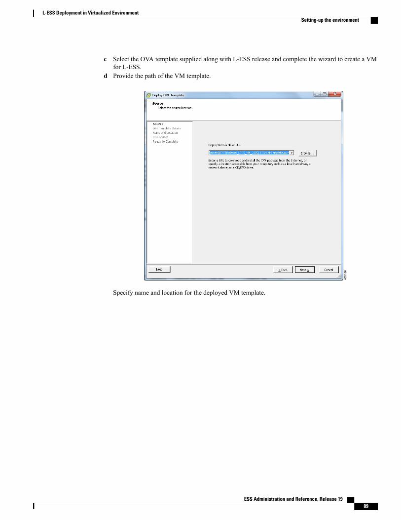
c Select the OVA template supplied along with L-ESS release and complete the wizard to create a VMfor L-ESS.
d Provide the path of the VM template.
Specify name and location for the deployed VM template.
ESS Administration and Reference, Release 19 89
L-ESS Deployment in Virtualized EnvironmentSetting-up the environment
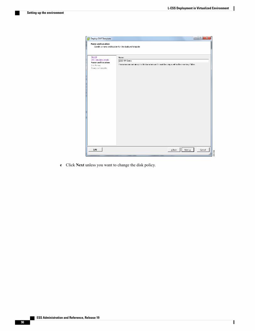
e Click Next unless you want to change the disk policy.
ESS Administration and Reference, Release 1990
L-ESS Deployment in Virtualized EnvironmentSetting-up the environment

Click Finish to start deployment task.
ESS Administration and Reference, Release 19 91
L-ESS Deployment in Virtualized EnvironmentSetting-up the environment

Deployment of the VM template will be complete with below message.
f You may want to edit the settings of the VM to change the resource allocation if needed. You can doso as shown below with the option to edit settings.
ESS Administration and Reference, Release 1992
L-ESS Deployment in Virtualized EnvironmentSetting-up the environment
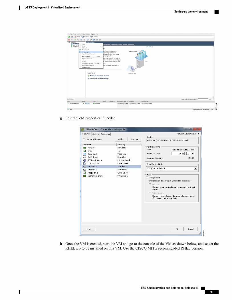
g Edit the VM properties if needed.
h Once the VM is created, start the VM and go to the console of the VM as shown below, and select theRHEL iso to be installed on this VM. Use the CISCO MITG recommended RHEL version.
ESS Administration and Reference, Release 19 93
L-ESS Deployment in Virtualized EnvironmentSetting-up the environment

i Restart the VM by providing "CTRL+ALT+DEL" signal using below option.
As VM reboots, it will enter into RHEL installation page.
ESS Administration and Reference, Release 1994
L-ESS Deployment in Virtualized EnvironmentSetting-up the environment
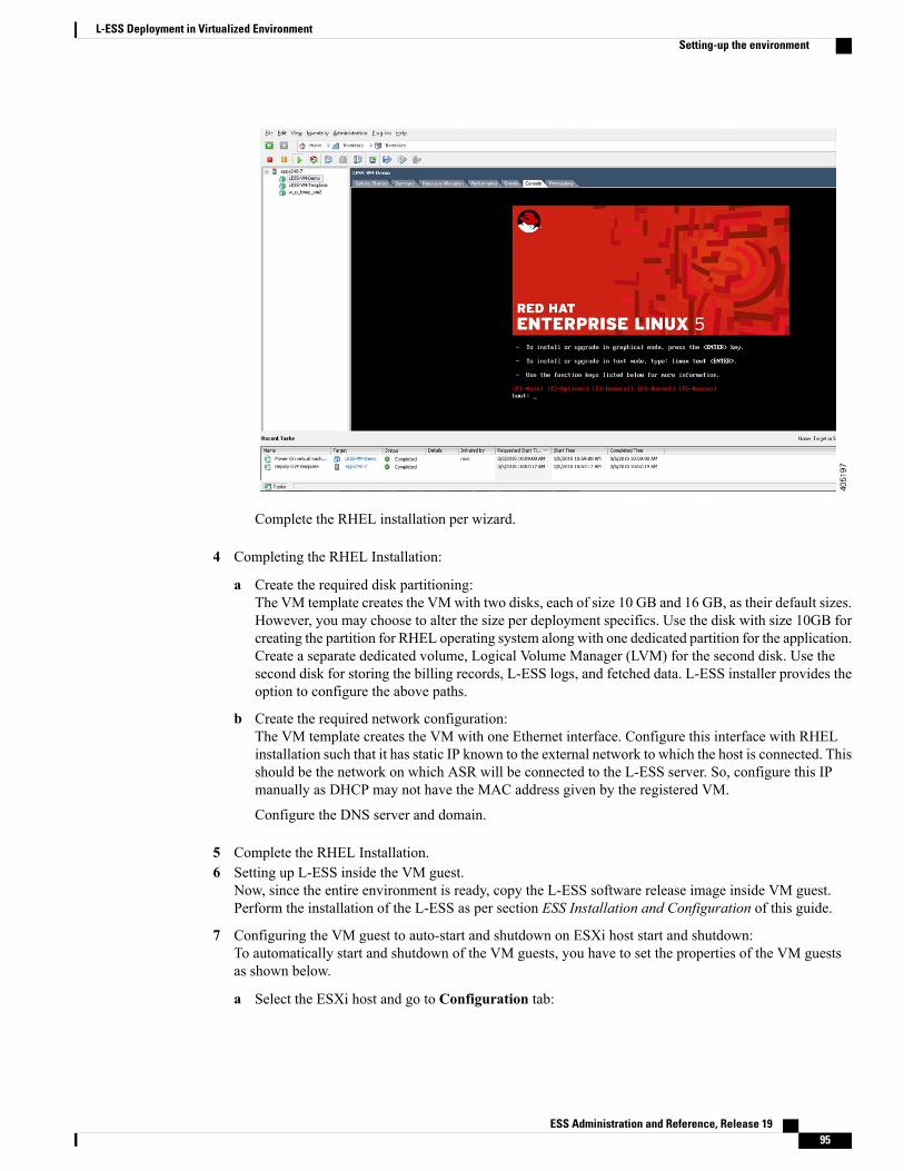
Complete the RHEL installation per wizard.
4 Completing the RHEL Installation:
a Create the required disk partitioning:The VM template creates the VMwith two disks, each of size 10 GB and 16 GB, as their default sizes.However, you may choose to alter the size per deployment specifics. Use the disk with size 10GB forcreating the partition for RHEL operating system along with one dedicated partition for the application.Create a separate dedicated volume, Logical Volume Manager (LVM) for the second disk. Use thesecond disk for storing the billing records, L-ESS logs, and fetched data. L-ESS installer provides theoption to configure the above paths.
b Create the required network configuration:The VM template creates the VM with one Ethernet interface. Configure this interface with RHELinstallation such that it has static IP known to the external network to which the host is connected. Thisshould be the network on which ASR will be connected to the L-ESS server. So, configure this IPmanually as DHCP may not have the MAC address given by the registered VM.
Configure the DNS server and domain.
5 Complete the RHEL Installation.6 Setting up L-ESS inside the VM guest.
Now, since the entire environment is ready, copy the L-ESS software release image inside VM guest.Perform the installation of the L-ESS as per section ESS Installation and Configuration of this guide.
7 Configuring the VM guest to auto-start and shutdown on ESXi host start and shutdown:To automatically start and shutdown of the VM guests, you have to set the properties of the VM guestsas shown below.
a Select the ESXi host and go to Configuration tab:
ESS Administration and Reference, Release 19 95
L-ESS Deployment in Virtualized EnvironmentSetting-up the environment
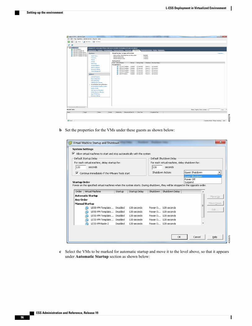
b Set the properties for the VMs under these guests as shown below:
c Select the VMs to be marked for automatic startup and move it to the level above, so that it appearsunder Automatic Startup section as shown below:
ESS Administration and Reference, Release 1996
L-ESS Deployment in Virtualized EnvironmentSetting-up the environment

Deploying product in cluster mode on a KVM-based GuestsThis section provides information on ESS System Recommendations and installation procedure in Clustermode on a Kernel-based Virtual Machine (KVM) guest.
ESS System Recommendations for KVM-based Guest - Cluster Mode• Cisco UCS C240 M3
◦2x Intel Xeon X5675 processors with 2x 16 GB DDR3 RAM
◦300GB SAS 10K RPM SFF Hard Disk Drive
◦Quad Gigabit Ethernet interfaces
◦Internal DVD-ROM drive
◦AC or DC power supplies depending on the application
• Sun 2540 M2 12 Disk Array AC, Sun 2501 M2 12-Disk Expansion Tray AC
◦12 x 600 GB 2.5" SAS HDD
◦Two redundant AC power supplies
–or–Oracle FS1 Storage
ESS Administration and Reference, Release 19 97
L-ESS Deployment in Virtualized EnvironmentDeploying product in cluster mode on a KVM-based Guests

• FS1-2 Pilot with 2 x Sun Servers X5-2
• HA Controller Pair with 4 x Intel E5-2620 6 Core CPUs
• 64 GB Cache
• 4 x 16 Gbps FC Host Ports
• 24 x 900 GB SAS-2 HDDs
• Operating Environment:
◦RHEL 6 with below packages.
◦Qemu KVM (1.5.0) onwards
◦virt-manager
◦libvirt
◦libvirt-python
◦python-virtinst
• Storage Foundation Cluster File System and High availability product 6.0 compatible for RHEL 5.9
Setting-up the EnvironmentFollow the below guidelines to prepare the operating environment.
1 Setup the two physical nodes for the cluster as specified under the Veritas Cluster Installation andManagement section of this guide.
a Install RHEL 6 on both the physical cluster nodes.b Setup the SAN storage between two physical cluster nodes as described under theConfiguring Storage
Array section of this guide.c Setup the Heartbeat link between two physical cluster nodes.
Create bridge interface for primary network interface and also for the network interfaces on whichheartbeat links are connected. Refer the section, and create three bridges br0, br1 and br2. Last two,br1 and br2, are for the heartbeat links. Do not allocate IP address to heartbeat link bridge interfaces.
Perform the same action for both the physical cluster nodes.
d Configure VM guest behavior on shutdown and start of the host as below:Make below changes to the file /etc/sysconfig/libvirt-guests on physical hosts.
Change the parameters as:ON_BOOT=startON_SHUTDOWN=shutdownSHUTDOWN_TIMEOUT=300
e Launch the VM guest :Refer section, and create VM on both the physical cluster nodes. Provide additional network bridgeinterface which will be used for heartbeat links as below:# ./less_vm_install.sh -n <less VM Name> -m <bridge interface> -i br1 -i br2 -I <pathfor RHEL ISO>
ESS Administration and Reference, Release 1998
L-ESS Deployment in Virtualized EnvironmentSetting-up the Environment
For example:# ./less_vm_install.sh -n lessAppVM -m br0 -i br1 -i br2-I/home/luser/cisco_rhel-5.9_15.0.26.0.isoComplete the RHEL Installation inside the VM guests. Do necessary IP addressing for the VM guestsso that both the guests are accessible to the external network.
f Attach the disks to the VM guests.Refer section, and attach the SAN storage disks to both the VMs through respective physical hosts.Ensure that the same disk from each host gets attached to both the VM as it will be used during failover.
If the mapping is not persistent, the VM will not have an attached disk when it reboots.Important
Installing Symantec SFCFSHA in VM GuestsLogin to one of the VM guests and perform the Symantec SFCFSHA 6.0 product installation. The installationprocedure inside the VM guests is same as per section Veritas Cluster Installation and Management. Thestorage is the disk attached to the VM guests and heartbeat links are the additional interfaces supplied to theVM guests. Veritas Installation and usage inside VM guests remains the same as it is for the physical hosts
Installing L-ESS in cluster modeRefer section Installing ESS Application in Cluster Mode of this guide and do the necessary installation ofL-ESS product.
Deploying product in Stand-alone mode on VMware basedGuests
This section provides information on ESS SystemRecommendations and installation procedure in Stand-alonemode on a VMware guest.
ESS System Recommendations for VMware based Guest - Stand-alone Mode• Cisco UCS C240 M3
◦2x Intel Xeon X5675 processors with 2x 16 GB DDR3 RAM
◦300GB SAS 10K RPM SFF Hard Disk Drive
◦Quad Gigabit Ethernet interfaces
◦Internal DVD-ROM drive
◦AC or DC power supplies depending on the application
• Optional:Sun 2540 M2 12 Disk Array AC, Sun 2501 M2 12-Disk Expansion Tray AC
ESS Administration and Reference, Release 19 99
L-ESS Deployment in Virtualized EnvironmentInstalling Symantec SFCFSHA in VM Guests
12 x 600 GB 2.5" SAS HDD◦
◦Two redundant AC power supplies
–or–Oracle FS1 Storage
• FS1-2 Pilot with 2 x Sun Servers X5-2
• HA Controller Pair with 4 x Intel E5-2620 6 Core CPUs
• 64 GB Cache
• 4 x 16 Gbps FC Host Ports
• 24 x 900 GB SAS-2 HDDs
• Operating Environment:
◦VMware hypervisor : ESXi-5.5.0-1331820-custom-Cisco-5.5.0.1.
Setting-up the environmentFollow the below guidelines to prepare the operating environment:
1 Install ESXiVMware ESXi is the bare-metal hypervisor. ESXi installs directly onto physical server enabling it to bepartitioned into multiple logical servers referred to as virtual machines. If the hardware on which L-ESSVM is to be launched does not have the VMware Hypervisor: ESXi, then download and install the ESXisoftware on the UCS box or blade using CIMC console and the physical disk or disk image of the software.
The recommended version is: ESXi-5.5.0-1331820-custom-Cisco-5.5.0.1.
Downloading the Customized VMware vSphere Hypervisor Image
Follow the below steps:
• Navigate to: https://my.vmware.com/web/vmware/loginThe VMware login page appears.
• Enter your VMware credentials, and then click Log in.If you do not have an account with VMware, click Register to create a free account.
• Click Downloads, and then select All Products from the drop-down list.
• To download the VMware vSphere Hypervisor 5.5 image, enterESXi-5.5.0-1331820-custom-Cisco-5.5.0.1.iso, in the Search field, and then click the Search icon.From the Search Results, click VMware vSphere > Drivers & Tools > CISCO Custom Image forESXi 5.5.0 GA Install CD, and then click Download.
2 Install vSphere ClientThe vSphere Client is a Windows program that you can use to configure the host and to operate its virtualmachines. You can obtain vSphere Client and its license fromVMware. Install the vSphere client compliantto the ESXi host.
Recommended version is: VMware-viclient-all-5.5.0
ESS Administration and Reference, Release 19100
L-ESS Deployment in Virtualized EnvironmentSetting-up the environment

3 Connect to ESXi host and create VM:
a Using the vSphere client, connect to the ESXi host with its IP address, administrative user, and passwordas shown below:
b Select option Deploy OVF Template from the File menu inside vSphere client.
ESS Administration and Reference, Release 19 101
L-ESS Deployment in Virtualized EnvironmentSetting-up the environment

c Select the OVA template supplied along with L-ESS release and complete the wizard to create a VMfor L-ESS.
d Provide the path of the VM template.
Specify name and location for the deployed VM template.
ESS Administration and Reference, Release 19102
L-ESS Deployment in Virtualized EnvironmentSetting-up the environment
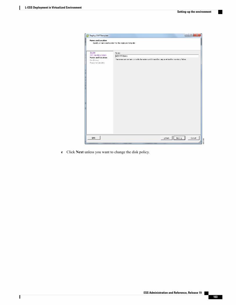
e Click Next unless you want to change the disk policy.
ESS Administration and Reference, Release 19 103
L-ESS Deployment in Virtualized EnvironmentSetting-up the environment
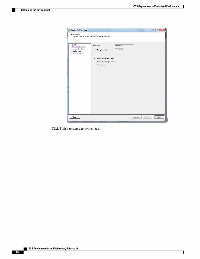
Click Finish to start deployment task.
ESS Administration and Reference, Release 19104
L-ESS Deployment in Virtualized EnvironmentSetting-up the environment

Deployment of the VM template will be complete with below message.
f You may want to edit the settings of the VM to change the resource allocation if needed. You can doso as shown below with the option to edit settings.
ESS Administration and Reference, Release 19 105
L-ESS Deployment in Virtualized EnvironmentSetting-up the environment
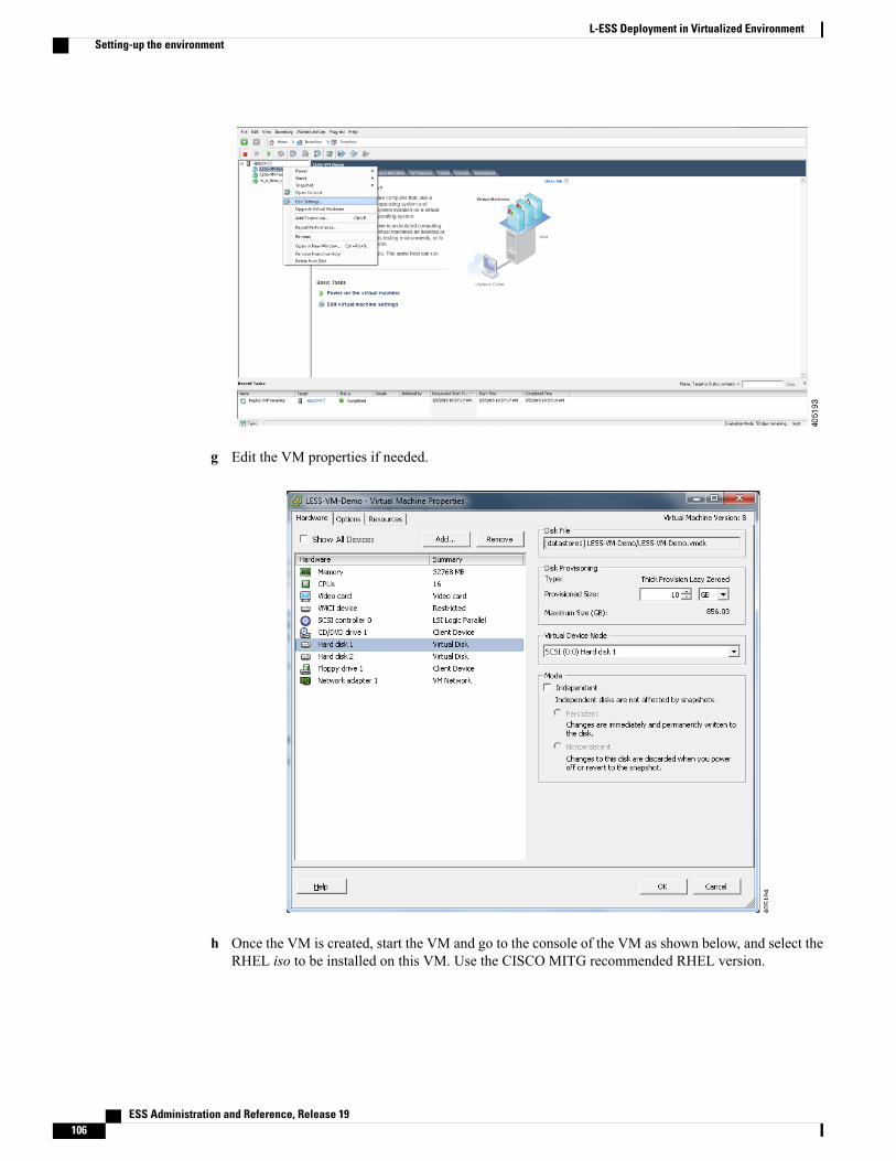
g Edit the VM properties if needed.
h Once the VM is created, start the VM and go to the console of the VM as shown below, and select theRHEL iso to be installed on this VM. Use the CISCO MITG recommended RHEL version.
ESS Administration and Reference, Release 19106
L-ESS Deployment in Virtualized EnvironmentSetting-up the environment
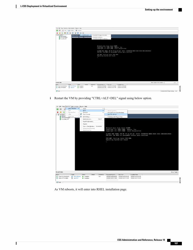
i Restart the VM by providing "CTRL+ALT+DEL" signal using below option.
As VM reboots, it will enter into RHEL installation page.
ESS Administration and Reference, Release 19 107
L-ESS Deployment in Virtualized EnvironmentSetting-up the environment

Complete the RHEL installation per wizard.
4 Completing the RHEL Installation:
a Create the required disk partitioning:The VM template creates the VMwith two disks, each of size 10 GB and 16 GB, as their default sizes.However, you may choose to alter the size per deployment specifics. Use the disk with size 10GB forcreating the partition for RHEL operating system along with one dedicated partition for the application.Create a separate dedicated volume, Logical Volume Manager (LVM) for the second disk. Use thesecond disk for storing the billing records, L-ESS logs, and fetched data. L-ESS installer provides theoption to configure the above paths.
b Create the required network configuration:The VM template creates the VM with one Ethernet interface. Configure this interface with RHELinstallation such that it has static IP known to the external network to which the host is connected. Thisshould be the network on which ASR will be connected to the L-ESS server. So, configure this IPmanually as DHCP may not have the MAC address given by the registered VM.
Configure the DNS server and domain.
5 Complete the RHEL Installation.6 Setting up L-ESS inside the VM guest.
Now, since the entire environment is ready, copy the L-ESS software release image inside VM guest.Perform the installation of the L-ESS as per section ESS Installation and Configuration of this guide.
7 Configuring the VM guest to auto-start and shutdown on ESXi host start and shutdown:To automatically start and shutdown of the VM guests, you have to set the properties of the VM guestsas shown below.
a Select the ESXi host and go to Configuration tab:
ESS Administration and Reference, Release 19108
L-ESS Deployment in Virtualized EnvironmentSetting-up the environment
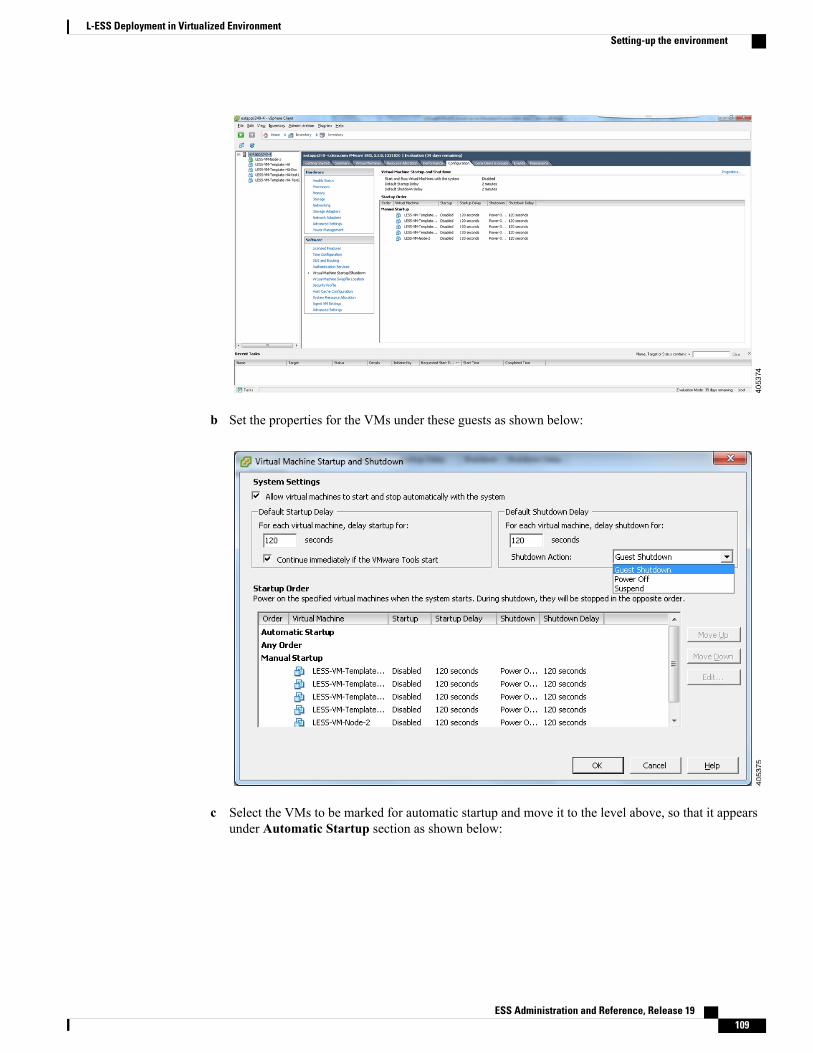
b Set the properties for the VMs under these guests as shown below:
c Select the VMs to be marked for automatic startup and move it to the level above, so that it appearsunder Automatic Startup section as shown below:
ESS Administration and Reference, Release 19 109
L-ESS Deployment in Virtualized EnvironmentSetting-up the environment
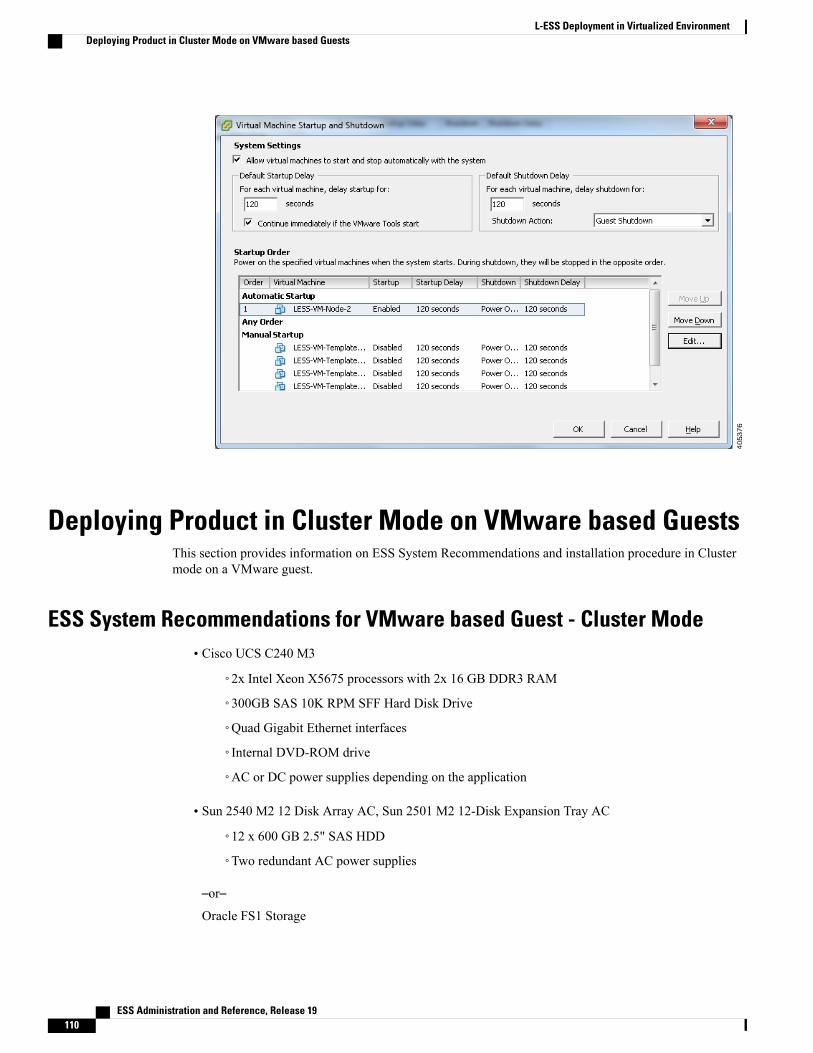
Deploying Product in Cluster Mode on VMware based GuestsThis section provides information on ESS System Recommendations and installation procedure in Clustermode on a VMware guest.
ESS System Recommendations for VMware based Guest - Cluster Mode• Cisco UCS C240 M3
◦2x Intel Xeon X5675 processors with 2x 16 GB DDR3 RAM
◦300GB SAS 10K RPM SFF Hard Disk Drive
◦Quad Gigabit Ethernet interfaces
◦Internal DVD-ROM drive
◦AC or DC power supplies depending on the application
• Sun 2540 M2 12 Disk Array AC, Sun 2501 M2 12-Disk Expansion Tray AC
◦12 x 600 GB 2.5" SAS HDD
◦Two redundant AC power supplies
–or–Oracle FS1 Storage
ESS Administration and Reference, Release 19110
L-ESS Deployment in Virtualized EnvironmentDeploying Product in Cluster Mode on VMware based Guests

• FS1-2 Pilot with 2 x Sun Servers X5-2
• HA Controller Pair with 4 x Intel E5-2620 6 Core CPUs
• 64 GB Cache
• 4 x 16 Gbps FC Host Ports
• 24 x 900 GB SAS-2 HDDs
• Operating Environment:
◦VMware hypervisor: ESXi-5.5.0-1331820-custom-Cisco-5.5.0.1
Setting-up the EnvironmentFollow the below guidelines to prepare the operating environment.
In the case of setting up HA cluster with two nodes, install ESXi hypervisor on both the UCS nodes.Important
1 Connect SAN storage to both the physical hosts as specified in this guide.2 Create a Logical Unit Number (LUN) on the SAN storage and map the same LUN to be available on both
the physical hosts as specified in the Configuring Storage using CAM section of this guide.3 Setup the two dedicated Ethernet Heartbeat links between the two ESXi hosts.4 Install the ESXi hypervisor on both the UCS hosts (For simplicity, let us address the UCS hosts as ESXi
hosts for now).5 As per guidelines provided in section Deploying product in Stand-alone mode on VMware based Guests,
on page 99, setup the VM guests on both the ESXi hosts. Use the OVA templateLESS-VM-Template-HA.ova bundled along with the L-ESS release. Install the RHELOperating Systemon both the VM guests created. However, do not setup the L-ESS application as yet. Also, mark the VMguests from both the ESXi hosts to start and shutdown automatically on ESXi host start and stop as specifiedin same section.
6 Add the SAN storage to both the ESXi hosts inventory as instructed below:
a Go to the ESXi host, Configuration tab and to the Storage (under Hardware) details.
ESS Administration and Reference, Release 19 111
L-ESS Deployment in Virtualized EnvironmentSetting-up the Environment
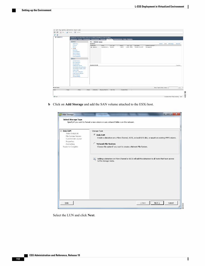
b Click on Add Storage and add the SAN volume attached to the ESXi host.
Select the LUN and click Next.
ESS Administration and Reference, Release 19112
L-ESS Deployment in Virtualized EnvironmentSetting-up the Environment
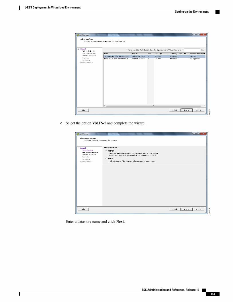
c Select the option VMFS-5 and complete the wizard.
Enter a datastore name and click Next.
ESS Administration and Reference, Release 19 113
L-ESS Deployment in Virtualized EnvironmentSetting-up the Environment

d Create a new virtual Disk from the SAN storage and map it to both the VMs.On ESXi host 1
1 Go to the VM settings and add the disk as shown below on ESXi host 1.
Do keep the VMs in shutdown state before adding the disk. Restart the VMs after adding the disks to VMresources as described in this section.
Important
ESS Administration and Reference, Release 19114
L-ESS Deployment in Virtualized EnvironmentSetting-up the Environment

2 Select Disk Provisioning as Thick Provision Eager Zeroed and also select the disk location asSpecify a datastore or datastore cluster.
ESS Administration and Reference, Release 19 115
L-ESS Deployment in Virtualized EnvironmentSetting-up the Environment
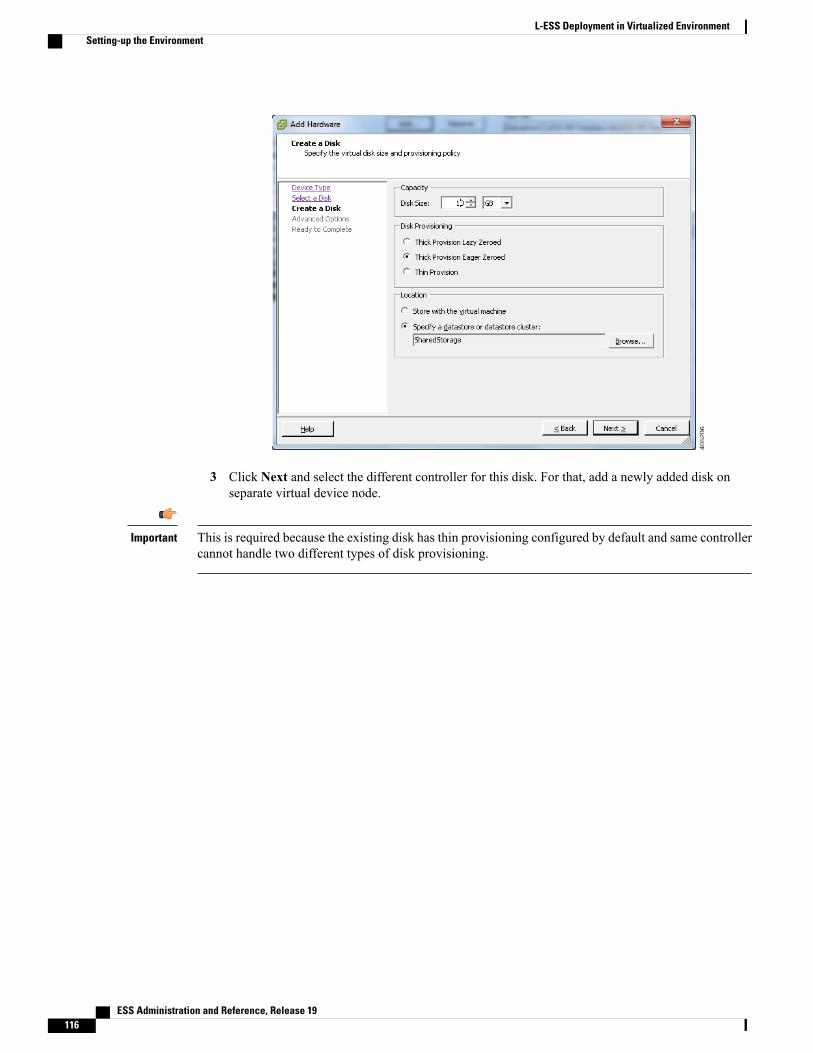
3 Click Next and select the different controller for this disk. For that, add a newly added disk onseparate virtual device node.
This is required because the existing disk has thin provisioning configured by default and same controllercannot handle two different types of disk provisioning.
Important
ESS Administration and Reference, Release 19116
L-ESS Deployment in Virtualized EnvironmentSetting-up the Environment
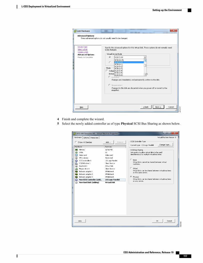
4 Finish and complete the wizard.5 Select the newly added controller as of type Physical SCSI Bus Sharing as shown below.
ESS Administration and Reference, Release 19 117
L-ESS Deployment in Virtualized EnvironmentSetting-up the Environment
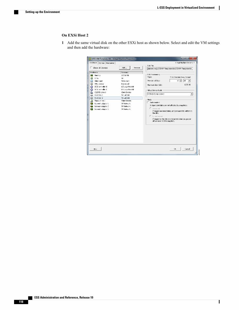
On EXSi Host 2
1 Add the same virtual disk on the other ESXi host as shown below. Select and edit the VM settingsand then add the hardware:
ESS Administration and Reference, Release 19118
L-ESS Deployment in Virtualized EnvironmentSetting-up the Environment
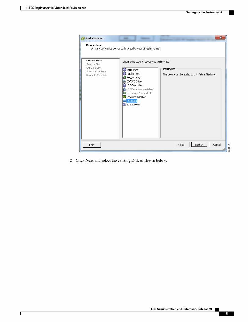
2 Click Next and select the existing Disk as shown below.
ESS Administration and Reference, Release 19 119
L-ESS Deployment in Virtualized EnvironmentSetting-up the Environment

On the second ESXi host, the existing disk that is created while setting up VM guest on ESXi host 1,needs to be added as both the guest should refer the same disk for HA solution.
Important
Select the datastore on which the disk was added on host1, and select the disk that is created byname of the VM provided on host1.
ESS Administration and Reference, Release 19120
L-ESS Deployment in Virtualized EnvironmentSetting-up the Environment

3 Again, dedicate a separate controller for this disk.
4 Select the newly added controller as of type Physical SCSI Bus Sharing, as shown below, sincevirtual disks needs to be shared between virtual machines.
ESS Administration and Reference, Release 19 121
L-ESS Deployment in Virtualized EnvironmentSetting-up the Environment

e After restarting the VM guests, check if the new disk is available inside RHEL using fdisk command.# fdisk -l
f Map the heartbeat link interfaces to the VMs.
a Create additional two network adapter at EXSi host inventory level. These would be used forheartbeat links. Follow the below steps:Go to Networking section of Configuration tab of the ESXi host.
ESS Administration and Reference, Release 19122
L-ESS Deployment in Virtualized EnvironmentSetting-up the Environment
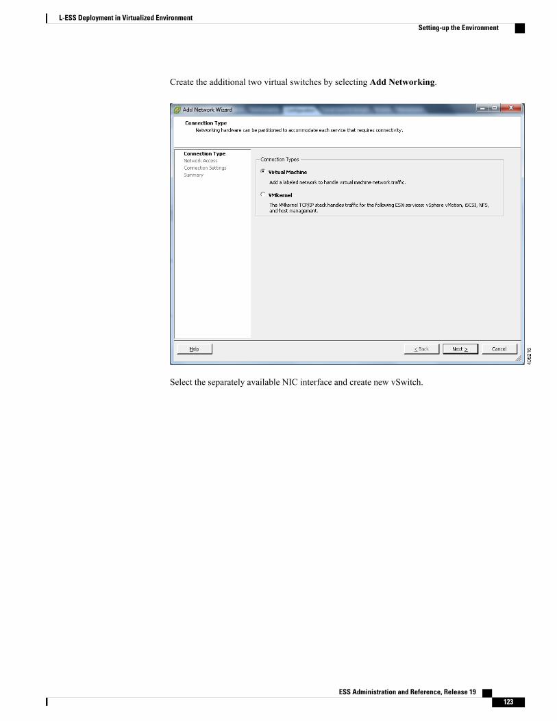
Create the additional two virtual switches by selecting Add Networking.
Select the separately available NIC interface and create new vSwitch.
ESS Administration and Reference, Release 19 123
L-ESS Deployment in Virtualized EnvironmentSetting-up the Environment
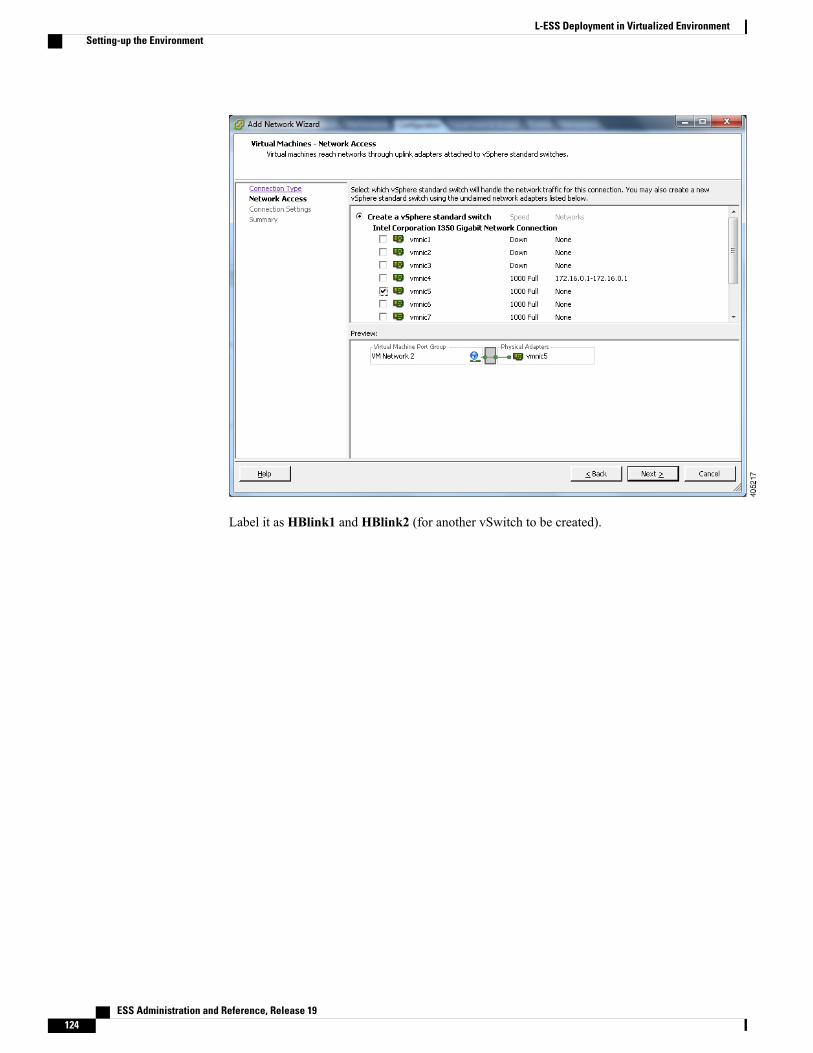
Label it as HBlink1 and HBlink2 (for another vSwitch to be created).
ESS Administration and Reference, Release 19124
L-ESS Deployment in Virtualized EnvironmentSetting-up the Environment
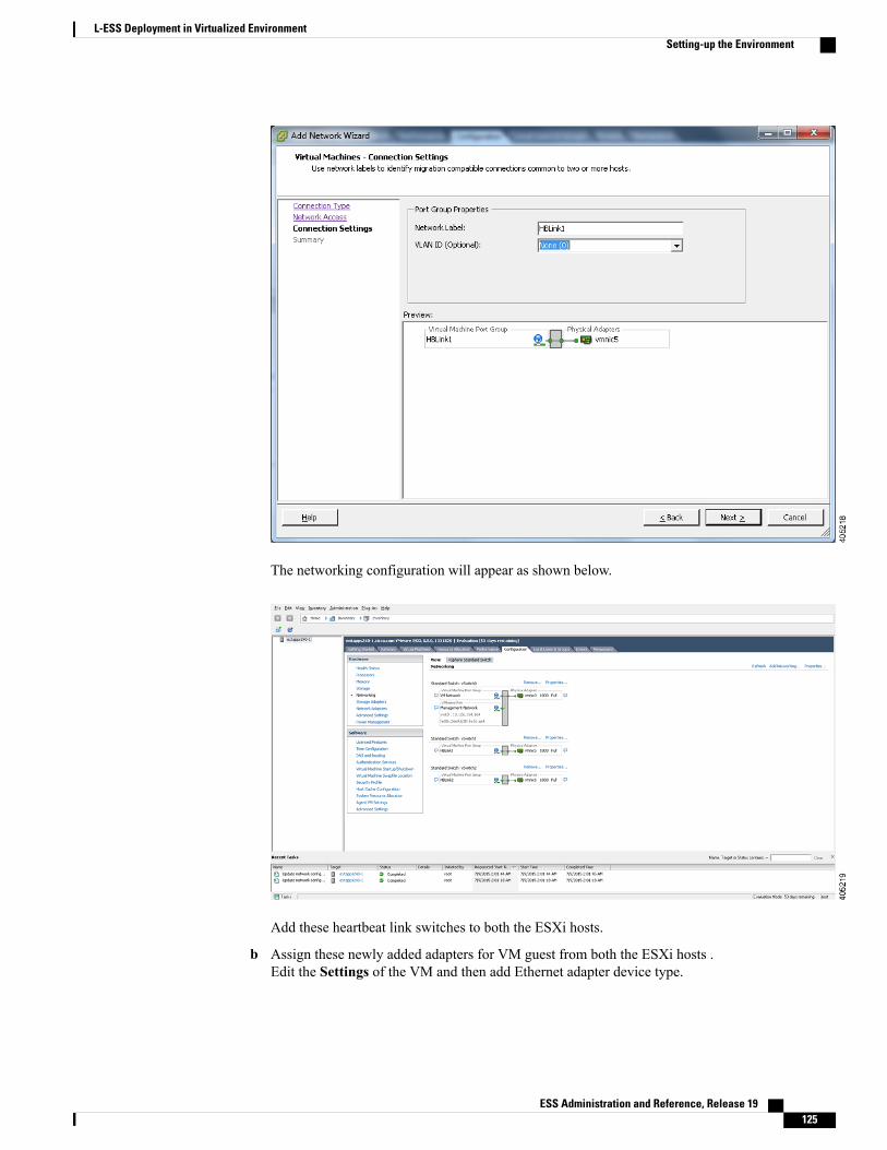
The networking configuration will appear as shown below.
Add these heartbeat link switches to both the ESXi hosts.
b Assign these newly added adapters for VM guest from both the ESXi hosts .Edit the Settings of the VM and then add Ethernet adapter device type.
ESS Administration and Reference, Release 19 125
L-ESS Deployment in Virtualized EnvironmentSetting-up the Environment
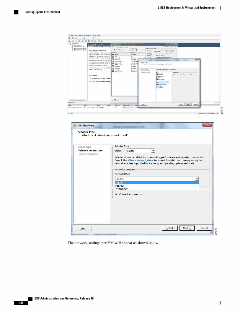
The network settings per VM will appear as shown below.
ESS Administration and Reference, Release 19126
L-ESS Deployment in Virtualized EnvironmentSetting-up the Environment

These NIC links would appear as heartbeat link interfaces inside the RHEL VM guests.
The Disk and Network interfaces are now available per VM for HA configuration.
Restart the VM Guests after adding the disk and network configurations.Important
Installing Symantec SFCFSHA in VM Guests.Login to one of the VM guest and perform the Symantec SFCFSHA 6.0 product installation. The installationprocedure inside the VM guests is same as per section Veritas Cluster Installation and Management of thisguide. The storage is the disk attached to the VM guests and heartbeat links are the additional interfacessupplied to the VM guests. Veritas Installation and usage inside VM guests remains same as it is for thephysical hosts.
Installing L-ESS in cluster modeRefer section Installing ESS Application in Cluster Mode of this guide and do the necessary installation ofL-ESS product.
ESS Administration and Reference, Release 19 127
L-ESS Deployment in Virtualized EnvironmentInstalling Symantec SFCFSHA in VM Guests.

ESS Administration and Reference, Release 19128
L-ESS Deployment in Virtualized EnvironmentInstalling L-ESS in cluster mode

C H A P T E R 6ESS Maintenance and Troubleshooting
This chapter includes the following topics:
• Using the Maintenance Utility, page 129
• Using ESS Logs, page 131
• ESS Server Scripts, page 131
• Troubleshooting the ESS, page 134
Using the Maintenance UtilityA shell script utility called serv is included with the ESS distribution at the <less_install_dir>/ess/ directory.This serv script can be used to manage the following processes of ESS Server:
• PS Monitor Application (PSMON)
• ESS
This utility can report the status of the ESS process on the system or it can be used to stop an instance of ESSprocess.
ESS must always be started with the serv script command.Important
Following are the options available with the serv script:
./serv { start | stop | forcestart | forcestop | switch | version | hoststatus | status[ <resource_name |resourcegroup_name> ] }
DescriptionKeyword
Use this command to start each ESS process and PSMON.start
Stops the running ESS process and PSMON.stop
ESS Administration and Reference, Release 19 129

DescriptionKeyword
Use this command to restart ESS and PSMON. This command will first stopalready running ESS processes and then restart each process.
forcestart
Use this command to forcibly stop ESS process and PSMON. If ESS is notstopped by serv stop command, this command will be used.
forcestop
Use this command to switchover the resource group.
This option can be used only in cluster modeinstallation.
Important
switch
Displays the status of each source and destination host.hoststatus
Displays the status of each of process/resource/resourcegroup.
For stand-alone mode:
• Process monitor tool
• Local External Storage Server
status
This command will show the version of ESS build. It will also show therevision date.
version
The following is a sample output of the serv status command:PID Process Status---------------------------------------------------------4270 PS Monitor Application Running- Local External Storage Server Not running
The following is a sample output of the serv hoststatus command:===================================================================Host ID State Status LastListedCount ProcessedCount
FailedCount===================================================================clustems2_edr_1269433964.51 Disabled - - 0
0clustems1_edr_1269434568.52 Enabled Pulling 0 294
610.4.4.93_edr_1269434878.55 Enabled Pulling 0 143
35
===================================================================Host ID State Status LastListedCount ProcessedCount
FailedCountt==================================================================local_edr_1269433964.54 Enabled Pushing 1 294
0local_data_1269434878.62 Enabled Pushing 1 143
0where,
• Host ID – source or destination name
• State – Source enabled/disabled for pull, or destination enabled/disabled for push
• Status – Current status of the source or destination
ESS Administration and Reference, Release 19130
ESS Maintenance and TroubleshootingUsing the Maintenance Utility

• LastListedCount – The latest count of files listed by the source or destination
• ProcessedCount – The number of files pulled/pushed successfully
• FailedCount – The number of files failed during the push/pull process
Using ESS LogsThe PSMON process logs memory usage threshold crossing alerts and other error and warning messages inthe watchdog.log file located in the <less_install_dir>/ess/log directory.
The PSMON process also sends alerts and messages to the configured e-mail address.
ESS stores all logs and other error and warning messages in a directory path configurable during installation.If this path is incorrect, then logs are stored in the <less_install_dir>/ess/log directory. See the Installing ESSApplication in Stand-alone Mode section in this guide for details.
The ESS creates separate log files for each ESS process (one file/ESS instance).
In 14.0 and later releases, the log file size can be a maximum of 50 MB.
In 9.0 and earlier releases, the log file size can be a maximum of 5 MB.
Each time ESS starts, a new directory is created under the log path directory. This directory uses the followingnaming conventions:
SERVER_LOG<Current date>_<Current time>
Paramiko related logs are also stored at the same location with file name paramiko.log.
ESS Server ScriptsThis section provides the function of the scripts available in the <less_install_dir>/ess directory, and theinformation on the usage of scripts. These scripts are mainly used for configuration management andmaintenance purposes.
This section includes the following topics:
Using the add_project ScriptTo avoid the impact of other applications running simultaneously on ESS Server, ESS tasks can be separatedby creating it as a Solaris project. This script is designed to add a dedicated project for ESS. The script addsproject "lessPrj" with ID 1001 and for the user essadmin. Depending on the underlying platform this scriptenables workload divisionmechanism.OnNetra 210 or Netra 245 server Fair Share Scheduler (FSS)mechanismis enabled and on T5220 server resource pool mechanism is enabled.
The script must be executed with superuser login before starting the ESS Server. In the cluster mode, thisscript must be executed on both the nodes of the cluster.
Important
To use the script, enter the following command from the <less_install_dir>/ess directory:./add_project.sh
ESS Administration and Reference, Release 19 131
ESS Maintenance and TroubleshootingUsing ESS Logs
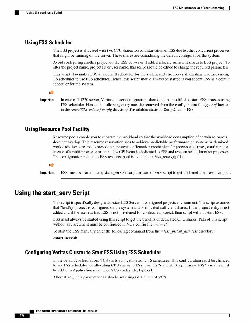
Using FSS SchedulerThe ESS project is allocated with two CPU shares to avoid starvation of ESS due to other concurrent processesthat might be running on the server. These shares are considering the default configuration the system.
Avoid configuring another project on the ESS Server or if added allocate sufficient shares to ESS project. Toalter the project name, project ID or user name, this script should be edited to change the required parameters.
This script also makes FSS as a default scheduler for the system and also forces all existing processes usingTS scheduler to use FSS scheduler. Hence, this script should always be started if you accept FSS as a defaultscheduler for the system.
In case of T5220 server, Veritas cluster configuration should not be modified to start ESS process usingFSS scheduler. Hence, the following entry must be removed from the configuration file types.cf locatedin the /etc/VRTSvcs/conf/config directory if available: static str ScriptClass = FSS
Important
Using Resource Pool FacilityResource pools enable you to separate the workload so that the workload consumption of certain resourcesdoes not overlap. This resource reservation aids to achieve predictable performance on systems with mixedworkloads. Resource pools provide a persistent configurationmechanism for processor set (pset) configuration.In case of a multi-processor machine few CPUs can be dedicated to ESS and rest can be left for other processes.The configuration related to ESS resource pool is available in less_pool.cfg file.
ESS must be started using start_serv.sh script instead of serv script to get the benefits of resource pool.Important
Using the start_serv ScriptThis script is specifically designed to start ESS Server in configured projects environment. The script assumesthat "lessPrj" project is configured on the system and is allocated sufficient shares. If the project entry is notadded and if the user starting ESS is not privileged for configured project, then script will not start ESS.
ESS must always be started using this script to get the benefits of dedicated CPU shares. Path of this script,without any argument must be configured in VCS config file, main.cf.
To start the ESS manually enter the following command from the <less_install_dir>/ess directory:./start_serv.sh
Configuring Veritas Cluster to Start ESS Using FSS SchedulerIn the default configuration, VCS starts application using TS scheduler. This configuration must be changedto use FSS scheduler for allocating CPU shares to ESS. For this "static str ScriptClass = FSS" variable mustbe added in Application module of VCS config file, types.cf.
Alternatively, this parameter can also be set using GUI client of VCS.
ESS Administration and Reference, Release 19132
ESS Maintenance and TroubleshootingUsing the start_serv Script

Using the Cleanup ScriptUse the deleteLocalFiles.sh script to delete files from local paths as a cleanup process. This script is requiredso that older files from the local destination, such as mediation, can be removed periodically. This ensuresthat there is no unnecessary disk space usage.
If the local destination deletes the file after picking up, then this script may not be required.
Files from ESS specific directories are deleted as soon as a fetched file is transferred to all of the configureddestinations. However, if the file is not pushed towards the destination, these skipped files keep accumulatingunder the destination's local temporary directory. You can use the cleanup script to regularly remove theseolder files from the temporary directories.
You should run the cleanup script from the ESS base directory.Important
How the Cleanup Script WorksUse this procedure to start and kill the deletelocalfiles.sh script manually.
Step 1 Provide the local paths from where files should be deleted periodically.These paths are taken as base paths and all of the older files below the base path are deleted at the configured time.Ifyou want to delete files from directory /home/ess/udr and /home/ess/edr, you can provide base path as /home/ess. Inother words if you provide path as /home/ess all of the older files from the directories below ess such as edr or udr willbe deleted.
Step 2 You can provide more than one path at a time so that the script deletes the files from more than one path../deleteLocalFiles.sh /home/ess /home/mediation /home/RESS
Since all older files below the base directory are deleted, make sure that you are providing only requiredpaths for the script.
Warning
The script reads the required parameters from the ess/ess config. The parameters and definitions are listed below:
• essdellocalrecordsexpirytime: Indicates the number of days after which the file is treated as an older file. If thisparameter is set to 0, the files will not be deleted.
• essdellocalrecordsstarttime: This value in hours indicates the starting hour when the ESS will start deleting olderfiles.
The above parameters read from config file are applied to all paths provided to thescript.
Important
Step 3 Start this script from /ess directory with the following command:./deleteLocalFiles.sh path1 [path2 path3 .. pathn ]
The logs for the cleanup script are generated in a file located at ess/log/deleteLocalFiles_%timestamp%.log.Important
ESS Administration and Reference, Release 19 133
ESS Maintenance and TroubleshootingUsing the Cleanup Script
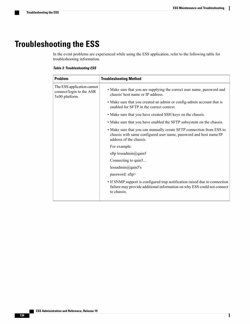
Troubleshooting the ESSIn the event problems are experienced while using the ESS application, refer to the following table fortroubleshooting information.
Table 3: Troubleshooting ESS
Troubleshooting MethodProblem
• Make sure that you are supplying the correct user name, password andchassis' host name or IP address.
• Make sure that you created an admin or config-admin account that isenabled for SFTP in the correct context.
• Make sure that you have created SSH keys on the chassis.
• Make sure that you have enabled the SFTP subsystem on the chassis.
• Make sure that you can manually create SFTP connection from ESS tochassis with same configured user name, password and host name/IPaddress of the chassis.
For example:
sftp lessadmin@qain5
Connecting to qain5...
lessadmin@qain5's
password: sftp>
• If SNMP support is configured trap notification raised due to connectionfailure may provide additional information on why ESS could not connectto chassis.
The ESS application cannotconnect/login to the ASR5x00 platform.
ESS Administration and Reference, Release 19134
ESS Maintenance and TroubleshootingTroubleshooting the ESS
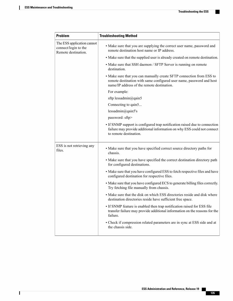
Troubleshooting MethodProblem
• Make sure that you are supplying the correct user name, password andremote destination host name or IP address.
• Make sure that the supplied user is already created on remote destination.
• Make sure that SSH daemon / SFTP Server is running on remotedestination.
• Make sure that you can manually create SFTP connection from ESS toremote destination with same configured user name, password and hostname/IP address of the remote destination.
For example:
sftp lessadmin@qain5
Connecting to qain5...
lessadmin@qain5's
password: sftp>
• If SNMP support is configured trap notification raised due to connectionfailure may provide additional information on why ESS could not connectto remote destination.
The ESS application cannotconnect/login to theRemote destination.
• Make sure that you have specified correct source directory paths forchassis.
• Make sure that you have specified the correct destination directory pathfor configured destinations.
• Make sure that you have configured ESS to fetch respective files and haveconfigured destination for respective files.
• Make sure that you have configured ECS to generate billing files correctly.Try fetching file manually from chassis.
• Make sure that the disk on which ESS directories reside and disk wheredestination directories reside have sufficient free space.
• If SNMP feature is enabled then trap notification raised for ESS filetransfer failure may provide additional information on the reasons for thefailure.
• Check if compression related parameters are in sync at ESS side and atthe chassis side.
ESS is not retrieving anyfiles.
ESS Administration and Reference, Release 19 135
ESS Maintenance and TroubleshootingTroubleshooting the ESS
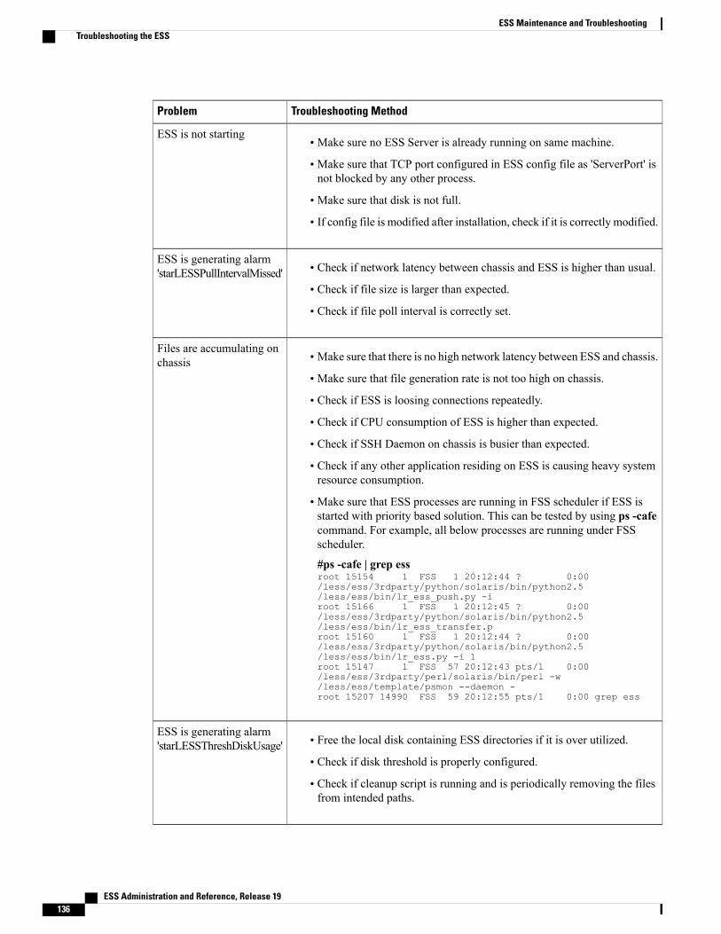
Troubleshooting MethodProblem
• Make sure no ESS Server is already running on same machine.
• Make sure that TCP port configured in ESS config file as 'ServerPort' isnot blocked by any other process.
• Make sure that disk is not full.
• If config file is modified after installation, check if it is correctly modified.
ESS is not starting
• Check if network latency between chassis and ESS is higher than usual.
• Check if file size is larger than expected.
• Check if file poll interval is correctly set.
ESS is generating alarm'starLESSPullIntervalMissed'
• Make sure that there is no high network latency between ESS and chassis.
• Make sure that file generation rate is not too high on chassis.
• Check if ESS is loosing connections repeatedly.
• Check if CPU consumption of ESS is higher than expected.
• Check if SSH Daemon on chassis is busier than expected.
• Check if any other application residing on ESS is causing heavy systemresource consumption.
• Make sure that ESS processes are running in FSS scheduler if ESS isstarted with priority based solution. This can be tested by using ps -cafecommand. For example, all below processes are running under FSSscheduler.
#ps -cafe | grep essroot 15154 1 FSS 1 20:12:44 ? 0:00/less/ess/3rdparty/python/solaris/bin/python2.5/less/ess/bin/lr_ess_push.py -iroot 15166 1 FSS 1 20:12:45 ? 0:00/less/ess/3rdparty/python/solaris/bin/python2.5/less/ess/bin/lr_ess_transfer.proot 15160 1 FSS 1 20:12:44 ? 0:00/less/ess/3rdparty/python/solaris/bin/python2.5/less/ess/bin/lr_ess.py -i 1root 15147 1 FSS 57 20:12:43 pts/1 0:00/less/ess/3rdparty/perl/solaris/bin/perl -w/less/ess/template/psmon --daemon -root 15207 14990 FSS 59 20:12:55 pts/1 0:00 grep ess
Files are accumulating onchassis
• Free the local disk containing ESS directories if it is over utilized.
• Check if disk threshold is properly configured.
• Check if cleanup script is running and is periodically removing the filesfrom intended paths.
ESS is generating alarm'starLESSThreshDiskUsage'
ESS Administration and Reference, Release 19136
ESS Maintenance and TroubleshootingTroubleshooting the ESS
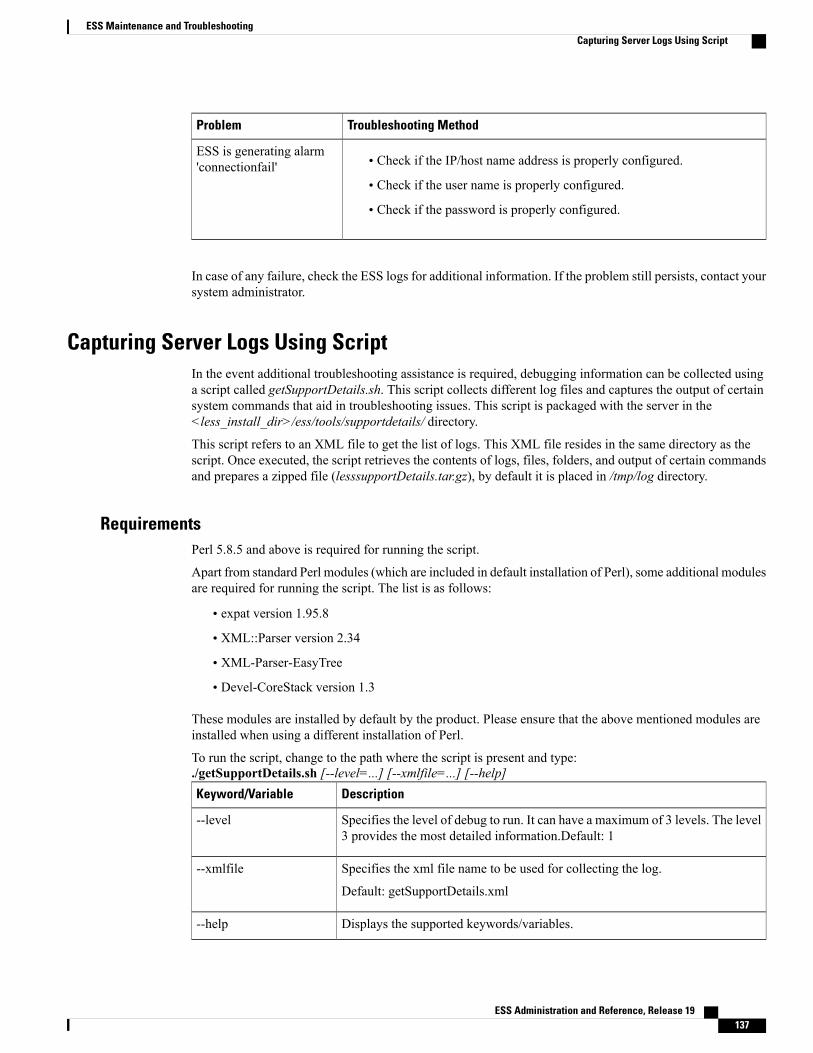
Troubleshooting MethodProblem
• Check if the IP/host name address is properly configured.
• Check if the user name is properly configured.
• Check if the password is properly configured.
ESS is generating alarm'connectionfail'
In case of any failure, check the ESS logs for additional information. If the problem still persists, contact yoursystem administrator.
Capturing Server Logs Using ScriptIn the event additional troubleshooting assistance is required, debugging information can be collected usinga script called getSupportDetails.sh. This script collects different log files and captures the output of certainsystem commands that aid in troubleshooting issues. This script is packaged with the server in the<less_install_dir>/ess/tools/supportdetails/ directory.
This script refers to an XML file to get the list of logs. This XML file resides in the same directory as thescript. Once executed, the script retrieves the contents of logs, files, folders, and output of certain commandsand prepares a zipped file (lesssupportDetails.tar.gz), by default it is placed in /tmp/log directory.
RequirementsPerl 5.8.5 and above is required for running the script.
Apart from standard Perl modules (which are included in default installation of Perl), some additional modulesare required for running the script. The list is as follows:
• expat version 1.95.8
• XML::Parser version 2.34
• XML-Parser-EasyTree
• Devel-CoreStack version 1.3
These modules are installed by default by the product. Please ensure that the above mentioned modules areinstalled when using a different installation of Perl.
To run the script, change to the path where the script is present and type:./getSupportDetails.sh [--level=...] [--xmlfile=...] [--help]
DescriptionKeyword/Variable
Specifies the level of debug to run. It can have a maximum of 3 levels. The level3 provides the most detailed information.Default: 1
--level
Specifies the xml file name to be used for collecting the log.
Default: getSupportDetails.xml
--xmlfile
Displays the supported keywords/variables.--help
ESS Administration and Reference, Release 19 137
ESS Maintenance and TroubleshootingCapturing Server Logs Using Script

For example, ./getSupportDetails.sh --level=3 --xmlfile=/tmp/getSupportDetails.xml
Supported Levels:
The logs that can be collected for different levels are as follows:
• Level 1:
◦Current status (running / not running) of the product
◦Current version of the installed product
◦Current Config files of the product
◦Output of the following commands:netstat -nrscstat
• Level 2:
◦Logs from Level 1
◦All Log files (Including Old Logs)
◦Information of Solaris version and current patch installed
◦Output of the following commands:On both Solaris and Linux:
netstat -nrifconfig -adf -vuname -aps -eafOn Solaris:
showrevprstat 1 1On Linux:
top -n 1 -benv
• Level 3:
◦Logs from level 2
◦Listing of directory pointed by "essbasedirectorypath" from ess_config file
◦Output of the following commands:On Linux:
rpm -q --all --queryformat'%-30{NAME}\t%{VERSION}\t%-60{SUMMARY}\t%{GROUP}\n'cat /proc/cpuinfocat /proc/meminfo
ESS Administration and Reference, Release 19138
ESS Maintenance and TroubleshootingCapturing Server Logs Using Script

On Solaris:
pkginfoprtdiag
ESS Administration and Reference, Release 19 139
ESS Maintenance and TroubleshootingCapturing Server Logs Using Script

ESS Administration and Reference, Release 19140
ESS Maintenance and TroubleshootingCapturing Server Logs Using Script
A P P E N D I X AxDR File Push Functionality
The ESS has the capability of simultaneously fetching any types of files from one or more chassis. That is,it can fetch CDR, EDR, NBR, UDR file, etc.
The chassis is configured such that the xDR files can either be pulled from chassis by ESS using pythonscripts, or the CDR files can be automatically pushed by chassis to any external server, in this case, ESS.ESS then forwards these files to the required destinations.
In the PUSH model, the transfer of CDR files will be done from within a context on the chassis. The filesare collected from the SMC hard disk or in-memory file system and will be transferred to ESS. Once the fileis transferred successfully, according to the configuration, the file will be either removed from the chassisor kept as is.
This Appendix includes the following topics:
• Configuring HDD, page 141
• Configuring Push Functionality, page 142
• ESS Directory Structure, page 144
• Log Maintenance, page 145
Configuring HDDTo use the hard disk for storing the EDR/UDR files, the following configuration needs to be applied.
configurecontext <context_name>
edr-module active-charging-servicecdr use-harddisk
endApplying this configuration results in EDR/UDR files to be transferred from RAMFS on the PSC card to thehard disk on the SMC card. On the hard disk, the EDR/UDR files are stored in the /records/edr and /records/udrdirectories respectively.
The default value of use-harddisk is set to FALSE, indicating that, by default, the usage of hard disk isdisabled.
ESS Administration and Reference, Release 19 141

This configuration can be applied either in EDR / UDR module, but it is applicable for both EDR and UDRmodules. Configuring in one of the modules prevents the configuration to be done in the other module. Hence,it is must to remove the configuration from the current module to apply it in the other module.
To disable the usage of hard disk, use the following command:
no cdr use-harddiskIn 12.3 and earlier releases, see theHDD Storage chapter in the AAA and GTPP Interface Administration andReference for more information on HDD. In 14.0 and later releases, refer to theGTPP Interface Administrationand Reference
Configuring Push FunctionalityBefore configuring the push functionality, you must make sure that the SSH Daemon (sshd) config on theexternal server is ready to receive the files.
Make sure that the SSH Daemon is running on the ESS server and has appropriate configuration forreceiving the files from one or more chassis.
Important
Make sure the following configuration changes are done in the /etc/ssh/sshd_config file on the ESS server.
• PasswordAuthentication yes
• UsePAM no
Any changes to the /etc/ssh/sshd_config file needs sshd to re-read the config file. For this to happen, get thepid of the sshd process and execute this command kill -1 <pid of the sshd>
Now, the sshd on the ESS is ready to receive the files from chassis using push mode. The push functionalitycan be configured on chassis.
To configure the push functionality, use the following command:
configurecontext <context_name>
edr-module active-charging-servicecdr { transfer-mode [ pull | push { primary { encrypted-url | url } <value> [ {
encrypted-secondary-url | secondary-url } ] ] | push-interval <push_interval> | remove-file-after-transfer| use-harddisk }
endNotes:
• If pull mode is selected, the ESS server pulls the xDR files from chassis. If push mode is selected, anapplication process on the chassis will be responsible for pushing the xDR files as and when needed.By default, the transfer mode is set to pull.
The change in the file transfer mode does not require any reboot of the chassis and ESS.Important
• Please note the following points before switching between transfer modes:
◦The chassis should first remove all temporary files and directories that are created while pushingfiles to ESS.
ESS Administration and Reference, Release 19142
xDR File Push FunctionalityConfiguring Push Functionality
◦Changing transfer mode from 'pull' to 'push' - You should first remove the entry of chassis' hostfrom the list of hosts maintained in ESS configuration file. Then disable 'pull' from ESS and changethe transfer mode to 'push' through the specified CLI command.
Make sure that the push server URL specified in the CLI is accessible from the localcontext. Also, make sure that the base directory mentioned contains edr and udrdirectories created within it.
Important
◦Changing transfer mode from 'push' to 'pull' - You should first disable 'push' from chassis and thenmanually remove the host directory of the chassis' from the base directory path.
After removing the host directory, ESS configuration file should be altered to have entry ofcorresponding chassis in pull hosts list.
Then, use the CLI command to enable 'pull' on ESS. Any of the ongoing push activity will continuetill all the file transfers scheduled is completed. If there is no push activity at the time of thisconfiguration change, all the push related configuration is nullified immediately.
• If push mode is selected, it is mandatory that you specify the ESS server URL to which the xDR filesneed to be transferred to. This allows user to configure a primary and a secondary server. Whenever afile transfer to the primary server fails for 4 times, the files will be transferred to the secondary server.The transfer will switch back to the primary server under the following conditions.
◦Transfer failures to secondary server for 4 times
◦Time elapsed for 30 minutes from the time it switched from primary server
The server can be specified in the standard URL format similar to the following:
scheme://user:password@host
Currently, for push, only sftp scheme is supported. Configuring a secondary server is optional.
For example:
cdr transfer-mode push primary url sftp://less-user:[email protected] server secondary secondary-urlsftp://less-user:[email protected]
• Once the file transfer is completed, the file is removed from the disk if remove-file is configured throughthe CLI. If not, the files are kept as is on the disk. Once the disk usage reaches a threshold limit, someof the files transferred already are removed to make room for new CDR files. By default, a file is removedafter its successful transfer.
Pushing xDR Files ManuallyTo manually push xDR files to the configured ESS, in the Exec mode, enter the following command:
cdr-push { all | local-filename <file_name> }Notes:
• Before you can use this command, in the EDR/UDR Configuration Mode, the CDR transfer mode andfile locations must be set to 'push'.
• <file_name> must be absolute path of the local file to push.
ESS Administration and Reference, Release 19 143
xDR File Push FunctionalityPushing xDR Files Manually
• If the file push is successful, the file name will have the prefix "tx." Also, the transferred files will bemoved to the /records/edr/TX directory. The prefix "prog." indicates the file transfer is in progress.
For the files that failed to transfer, "failed." is added as a prefix to the file name.
A new temporary directory named "TX" is created within /records/edr and /records/udrdirectories during the push activity. This directory contains the successfully pushedfiles. Tampering of any of the directories/files within /records file system is not allowed,and doing so may result into an unexpected behavior.
Important
During the push activity, if one more push is triggered i.e., either due to a periodic timer expiry or due to amanual push, then the push request is queued. Once the first push is completed, the queued request will beprocessed. At any time, there can be a maximum of one periodic push and one manual push that can be queued.Once the queue is full, the subsequent push triggers are ignored / failed.
ESS Directory StructureThis section describes the internal directory structure of the ESS server.
The chassis creates individual directories by its name under the base directory. Also, separate sub-directoriesare created for edr and udr under the chassis' directory. Thus, the directory structure should be similar to thefollowing:
|_____ <Local data directory > e.g. /less/ess/data
| |_____<STX-1> e.g. /less/ess/data/stx-1
| | |_____udr
| | | |______temp
| | | |______temp_dest1
| | | |______temp_dest2
| | | |______temp_dest3
| | |_____edr
| | | |______temp
| | | |______temp_dest1
| | | |______temp_dest2
| | | |______temp_dest3
| |_____<STX-2> e.g. /less/ess/data/stx-2
| | |_____udr
| | | |______temp
| | | |______temp_dest1
| | | |______ temp_dest2
| | | |______ temp_dest3
| | |_____edr
ESS Administration and Reference, Release 19144
xDR File Push FunctionalityESS Directory Structure
| | | |______ temp
| | | |______ temp_dest1
| | | |______ temp_dest2
| | | |______ temp_dest3
The STX-n indicates the name of the chassis.
In case of cluster environment, the chassis is configured to push the files to central location on shared disk sothat active ESS cluster nodes will be able to retrieve the files in case of switchover / failover.
In case of any chassis failure during file transfer, it will push the half-cooked file again. Since chassis ispushing the files to ESS, missing of any files is reported by chassis and if some files are deleted due toinsufficient disk space, the chassis generates an alarm.
Log MaintenanceThis section provides information on the logs maintained during file transfer.
The file transfer script generates separate logs like the pull and push process under the configured log directory.The script creates separate directory for the logs as shown below:
Log directory name: FTRANSFER_LOG_date_time
Log file name: ftransfer.log
The file transfer process generates logs under the following events:
•When script is started
• Detection of addition or removal of new host
• Detection of UDR or EDR files addition or removal
• Successful transfer of file (Link creation or copy operation)
• Failure during transfer of file (Link creation or copy operation)
ESS Administration and Reference, Release 19 145
xDR File Push FunctionalityLog Maintenance

ESS Administration and Reference, Release 19146
xDR File Push FunctionalityLog Maintenance