ESPOO 2007 Tarja Häkkinen, Sirje Vares, Pekka Huovila ... · VTT TIEDOTTEITA Œ RESEARCH NOTES...
212
ESPOO 2007 VTT RESEARCH NOTES 2401 Tarja Häkkinen, Sirje Vares, Pekka Huovila, Erkki Vesikari, Janne Porkka, Lars-Olof Nilsson, Åse Togerö, Carl Jonsson, Katarina Suber, Ronny Andersson, Robert Larsson & Isto Nuorkivi ICT for whole life optimization of residential buildings Skanska Moderna Hus Concept ILCD Toolbox EKOMETER LifePlan Ennus-Concrete Suppliers data SABO (experience data) Database Comparison Interface Database Maintenance Plan Data LCC LCA Maintenance Plan Data Interface Ennus-Wood Ennus-Steel EcoProP Skanska Moderna Hus Concept ILCD Toolbox EKOMETER LifePlan Ennus-Concrete Suppliers data SABO (experience data) Database Comparison Interface Database Maintenance Plan Data LCC LCA Maintenance Plan Data Interface Ennus-Wood Ennus-Steel EcoProP
-
Upload
truongkien -
Category
Documents
-
view
214 -
download
0
Transcript of ESPOO 2007 Tarja Häkkinen, Sirje Vares, Pekka Huovila ... · VTT TIEDOTTEITA Œ RESEARCH NOTES...
VTT R
ESEAR
CH
NO
TES 2401 ICT for w
hole life optimization of residential buildings
ESPOO 2007 VTT RESEARCH NOTES 2401
The research project "ICT for whole life optimisation of residentialbuildings" developed and tested the whole life design and optimisationmethods for residential buildings. The project defined that an industrialisedbuilding process is characterised by two main elements: a building conceptbased approach and efficient information management. Building conceptbased approach enables 1) the product development of the end product,2) repetition of the basic elements of the building from one project to othersand 3) customisation of the end-product considering the specific needs ofthe case and the client. Information management enables 1) the considerationof wide spectrum of aspects including building performance, environmentalaspects, life cycle costs and service life, and 2) rapid adapting of the designto the specific requirements of the case. This report presents the results ofthe project and introduces the case studies.
Tarja Häkkinen, Sirje Vares, Pekka Huovila,Erkki Vesikari, Janne Porkka, Lars-Olof Nilsson,Åse Togerö, Carl Jonsson, Katarina Suber,Ronny Andersson, Robert Larsson & Isto Nuorkivi
ICT for whole life optimization ofresidential buildings
ISBN 978-951-38-6948-9 (URL: http://www.vtt.fi/publications/index.jsp)ISSN 1455-0865 (URL: http://www.vtt.fi/publications/index.jsp)
SkanskaModerna Hus
Concept
ILCD
Toolbox
EKOMETER
LifePlan
Ennus-ConcreteSuppliers
data
SABO(experience
data)
DatabaseComparison
InterfaceDatabase
Maintenance Plan Data LCC
LCA
Maintenance Plan Data
Interface
Ennus-Wood
Ennus-Steel
EcoProPSkanska
Moderna Hus Concept
ILCD
Toolbox
EKOMETER
LifePlan
Ennus-ConcreteSuppliers
data
SABO(experience
data)
DatabaseComparison
InterfaceDatabase
Maintenance Plan Data LCC
LCA
Maintenance Plan Data
Interface
Ennus-Wood
Ennus-Steel
EcoProP
VTT VTT VTTPL 1000 PB 1000 P.O. Box 1000
02044 VTT 02044 VTT FI-02044 VTT, FinlandPuh. 020 722 4404 Tel. 020 722 4404 Phone internat. + 358 20 722 4404Faksi 020 722 4374 Fax 020 722 4374 Fax + 358 20 722 4374

VTT TIEDOTTEITA � RESEARCH NOTES 2401
ICT for whole life optimization of residential buildings
Tarja Häkkinen, Sirje Vares, Pekka Huovila, Erkki Vesikari & Janne Porkka
VTT Technical Research Centre of Finland
Lars-Olof Nilsson & Åse Togerö Lund University
Carl Jonsson & Katarina Suber Skanska Sverige AB
Ronny Andersson & Robert Larsson Cementa
Isto Nuorkivi Skanska Oyj

ISBN 978-951-38-6948-9 (URL: http://www.vtt.fi/publications/index.jsp) ISSN 1455-0865 (URL: http://www.vtt.fi/publications/index.jsp) Copyright © VTT 2007
JULKAISIJA � UTGIVARE � PUBLISHER
VTT, Vuorimiehentie 3, PL 1000, 02044 VTT puh. vaihde 020 722 111, faksi 020 722 4374
VTT, Bergsmansvägen 3, PB 1000, 02044 VTT tel. växel 020 722 111, fax 020 722 4374
VTT Technical Research Centre of Finland, Vuorimiehentie 3, P.O.Box 1000, FI-02044 VTT, Finland phone internat. +358 20 722 111, fax +358 20 722 4374
VTT, Lämpömiehenkuja 2, PL 1000, 02044 VTT puh. vaihde 020 722 111, faksi 020 722 7055
VTT, Värmemansgränden 2, PB 1000, 02044 VTT tel. växel 020 722 111, fax 020 722 7055
VTT Technical Research Centre of Finland, Lämpömiehenkuja 2, P.O. Box 1000, FI-02044 VTT, Finland phone internat. +358 20 722 111, fax +358 20 722 7055
Technical editing Anni Kääriäinen

3
Häkkinen, Tarja, Vares, Sirje, Huovila, Pekka, Vesikari, Erkki, Porkka, Janne, Nilsson, Lars-Olof, Togerö, Åse, Jonsson, Carl, Suber, Katarina, Andersson, Ronny, Larsson, Robert & Nuorkivi, Isto. ICT for whole life optimisation of residential buildings. Espoo 2007. VTT Tiedotteita � Research Notes 2401.207 p.
Keywords life cycle, integrated, buildings, design, industrialised
Abstract
The research project �ICT for whole life optimisation of residential buildings� (ICTWLORB) developed and tested the whole life design and optimisation methods for residential buildings. The objective of the ICTWLORB project was to develop and implement an ICT based tool box for integrated life cycle design (ILCD) of residential buildings. ICTWLORB was performed in cooperation with Swedish and Finnish partners.
The ICTWLORB project defined as a premise that an industrialised building process is characterised by two main elements: a building concept based approach and efficient information management. Building concept based approach enables 1) the product development of the end product, 2) repetition of the basic elements of the building from one project to others and 3) customisation of the end-product considering the specific needs of the case and the client. Information management enables 1) the consideration of wide spectrum of aspects including building performance, environmental aspects, life cycle costs and service life, and 2) rapid adapting of the design to the specific requirements of the case.
ILCD calls for the development of new kinds of tools and databases. In the traditional building process the information management is difficult to realise because the time to collect data, make assessments and comparisons, and correct decisions is too short. However, in the industrialized process the technical solutions are developed separately for launch to a concept, and thus ILCD is easier to realise. The tools used today should undergo a change from advanced engineering tools to solutions more suitable for development and application of concepts. For the development of concepts, there is a possibility to use sophisticated expert tools. For the application in projects, we may only use the tabulated results, and simple combinations suitable for customisation of the design option.
4
Preface
The research project �ICT for whole life optimisation of residential buildings� (ICTWLORB) (2006�2007) belonged to the ERABUILD research programme. The objective of the ICTWLORB project was to develop and implement an ICT based tool box for integrated life cycle design of residential buildings.
ICTWLORB was performed in cooperation with Swedish and Finnish partners:
− Lund University, project coordinator − VTT Technical Research Centre of Finland − Skanska Sverige AB − Skanska Oyj − Cementa AB.
The project was funded by Tekes � Finnish Funding Agency for Technology and Innovation and FORMAS and by the participating organisations. The specific objectives of the project were as follows:
− to structure integrated life cycle design methodology for buildings
− to collect and formulate ICT based tools and data bases for requirements management and life cycle design of buildings
− to develop, consolidate and link these tools and data bases in order to form an ICT based toolbox for integrated life cycle design
− to test and implement the toolbox in building projects
− to formulate guidelines for the use of the integrated life cycle design toolbox.
5
Contents
Abstract..............................................................................................................................3
Preface ...............................................................................................................................4
Chapter 1 .........................................................................................................................10
1. Introduction................................................................................................................11 1.1 Objectives and purpose of the project ..............................................................11 1.2 Approach ..........................................................................................................11 1.3 Life-cycle management of buildings from the viewpoint of industrialised
building.............................................................................................................15 References..................................................................................................................21
Chapter 2 .........................................................................................................................22
2. Life cycle methodology for buildings � regulatory and methodological framework .....23 2.1 Introduction ......................................................................................................23 2.2 Life cycle approach in the context of sustainable development
strategies of the EU ..........................................................................................24 2.3 Building regulatory and standardisation framework for the life cycle
management of buildings .................................................................................25 2.3.1 Construction Product Directive............................................................26 2.3.2 Harmful chemicals and health effects ..................................................26 2.3.3 Energy Performance of Buildings........................................................27 2.3.4 Standards for life-cycle assessment and service life design of buildings.... 27 2.3.5 Life Cycle Assessment (LCA) .............................................................29 2.3.6 Life cycle costing (LCC)......................................................................29
2.4 Methodologies for life cycle management of buildings ...................................31 2.4.1 Sustainability indicators for building ...................................................31 2.4.2 National environmental assessment and classification
methods for buildings and building products.......................................32 2.4.3 Methodologies for requirement management ......................................35 2.4.4 Methodologies for service life management ........................................36
2.5 Usability and restrictions of life cycle management methodologies................39 2.5.1 Requirement setting .............................................................................40 2.5.2 Design for required performance .........................................................40 2.5.3 Declaration ...........................................................................................41 2.5.4 Industrialised building processes .........................................................42
References..................................................................................................................42

6
Chapter 3 .........................................................................................................................47
3. The industrialised building process ...........................................................................48 3.1 Main ingredients in the industrialised building process ...................................48 3.2 Why choose an industrialised building process?..............................................49 3.3 Components and interfaces...............................................................................50 3.4 Concepts and projects.......................................................................................51 3.5 The process phases and product models...........................................................52 3.6 The planning phase...........................................................................................53 3.7 The execution phase .........................................................................................55 3.8 Different ways to apply a building concept......................................................57 3.9 What is most important to hold on to in a building concept?...........................58 3.10 Traditional and industrialised design processes in a concept...........................58 3.11 Production cost .................................................................................................60 3.12 Concept maintenance and concept life cycle....................................................61 3.13 ILCD tools in the industrialised process ..........................................................63 3.14 Summary and conclusions................................................................................63 References..................................................................................................................64
Chapter 4 .........................................................................................................................65
4. Whole-life optimisation of buildings and BIMs ........................................................66 4.1 Introduction ......................................................................................................66 4.2 Product information..........................................................................................67 4.3 Building Information Model � BIM.................................................................69 4.4 Integration of product information with BIMs.................................................71 4.5 Product libraries ...............................................................................................74 4.6 Techniques for publishing and finding product information in web................76 4.7 Case LifePlan ...................................................................................................77 4.8 Case ENNUS CONCRETE..............................................................................81 4.9 Conclusions ......................................................................................................83 References..................................................................................................................84
Chapter 5 .........................................................................................................................87
5. Toolbox � Methodologies and tools for ILC-Design and ILC-Customisation & Configuration .............................................................................................................88 5.1 Introduction ......................................................................................................88 5.2 Integrated life cycle design...............................................................................88 5.3 The traditional building process .......................................................................90 5.4 The industrialised building process ..................................................................91 5.5 The Toolbox � examples of tools to use in an ILC Design or
Customisation/Configuration ...........................................................................95
7
5.6 Description of tools ..........................................................................................98 References................................................................................................................107
Chapter 6 .......................................................................................................................109
6. Case studies..............................................................................................................111 6.1 Introduction ....................................................................................................111 6.2 EcoProP/ModernaHus ....................................................................................111
6.2.1 EcoProP tool.......................................................................................111 6.2.2 Skanska�s ModernaHus concept ........................................................113 6.2.3 Requirements management in Skanska�s Almby housing
project in Örebro ................................................................................115 6.2.4 Experiences and feedback ..................................................................115 6.2.5 Conclusions ........................................................................................117
6.3 Service-life tools for concrete structures........................................................120 6.3.1 Background ........................................................................................120 6.3.2 Traditional concrete durability design ...............................................120 6.3.3 ENNUS-Concrete...............................................................................122
6.3.3.1 Background .........................................................................122 6.3.3.2 Service-life with respect to frost in exposure classes
XF1 and XF3 (without salts)...............................................124 6.3.3.3 Service-life with respect to corrosion in exposure
classes XC1 to XC4 (without salts) ....................................128 6.3.3.4 Service-life with respect to frost in exposure classes
XF2 and XF4 (with de-icing salts)......................................130 6.3.3.5 Conclusion ..........................................................................130
6.3.4 SBF-SLD-tool ....................................................................................131 6.3.4.1 Background .........................................................................131 6.3.4.2 Principles of performance based service-life design...........132 6.3.4.3 Frost ....................................................................................134 6.3.4.4 Frost and salt .......................................................................135 6.3.4.5 Carbonation-initiated reinforcement corrosion...................136 6.3.4.6 Chloride-initiated reinforcement corrosion.........................137 6.3.4.7 Consequences of corrosion .................................................138 6.3.4.8 Environmental actions on concrete structures ....................140 6.3.4.9 Methods for determining new material and
environmental parameters ...................................................140 6.3.4.10 Conclusions.........................................................................140
6.3.5 References ..........................................................................................140 6.4 LifePlan/Ecometer..........................................................................................142
6.4.1 Introduction of LifePlan and Ecometer..............................................142 6.4.1.1 Ecometer .............................................................................142

8
6.4.1.2 LifePlan and LCA ...............................................................142 6.4.2 Purpose of the case study ...................................................................143 6.4.3 Case study ..........................................................................................143
6.5 LifePlan/ModernaHus ....................................................................................144 6.5.1 Introduction of LifePlan.....................................................................144 6.5.2 Purpose of the case study ...................................................................146 6.5.3 Case study ..........................................................................................147 6.5.4 Data supply for LifePlan database, guide ..........................................149 6.5.5 Discussions/problems.........................................................................154
References................................................................................................................155 6.6 Lifecycle costs for industrialised concept buildings � experiences
of applying LCC spreadsheet to ModernaHus ...............................................155 6.6.1 Introduction ........................................................................................155 6.6.2 Objectives...........................................................................................155 6.6.3 Introduction to LCC and ILCD..........................................................156 6.6.4 Description of tested tools..................................................................160
6.6.4.1 LCC Spreadsheet.................................................................160 6.6.4.2 Life cycle cost data .............................................................162 6.6.4.3 Calculation horizon .............................................................162 6.6.4.4 End of the life cycle ............................................................163 6.6.4.5 Verification of the LCC tool ...............................................164 6.6.4.6 Full LCA method ................................................................165 6.6.4.7 VIP+ (energy balance calculation)......................................166
6.6.5 Description of ModernaHus...............................................................166 6.6.6 Results from the case study................................................................168
6.6.6.1 Theory is put into practice ..................................................168 6.6.6.2 LCC Spreadsheet.................................................................169 6.6.6.3 Energy calculation using VIP+ ...........................................170 6.6.6.4 Basis for calculations ..........................................................171 6.6.6.5 Sensitivity analysis..............................................................172 6.6.6.6 Calculation results...............................................................173
6.6.7 Analyse and conclusions ....................................................................176 6.6.7.1 LCC methodology applied to an industrialised building
process.................................................................................177 References ......................................................................................................179
6.7 Risks of non-performance in industrialized construction...............................181 6.7.1 Abstract ..............................................................................................181 6.7.2 Introduction ........................................................................................181 6.7.3 A hypothesis on variations in expected performance in principle .....182 6.7.4 Quantification of uncertainties � some examples ..............................185 6.7.5 Uncertainties included in life-cycle cost calculations........................190

9
6.7.6 Discussion and conclusions................................................................193 6.7.7 Acknowledgements ............................................................................193 References ......................................................................................................193
Chapter 7 .......................................................................................................................195
7. Summary and conclusions .......................................................................................196 7.1 Summary and conclusions from each chapter ................................................196
7.1.1 The project � objectives and approach...............................................196 7.1.2 Life cycle methodology for buildings � regulatory and methodological framework.............................................................................197 7.1.3 The industrialized building process ...................................................198 7.1.4 Whole-life optimisation of buildings and BIMs ................................199 7.1.5 Toolbox � Methodologies and tools for ILC-D and ILC-C ...............200 7.1.6 Case studies........................................................................................200
7.2 Recommendations for implementation...........................................................205 7.3 Future research and development...................................................................206 References................................................................................................................207

10
Chapter 1
Authors Tarja Häkkinen and Ronny Andersson
Contents
1. Introduction................................................................................................................11 1.1 Objectives and purpose of the project ..............................................................11 1.2 Approach ..........................................................................................................11 1.3 Life-cycle management of buildings from the viewpoint of industrialised
building.............................................................................................................15 References..................................................................................................................21
11
1. Introduction
1.1 Objectives and purpose of the project
There is currently a strong trend towards rationalisation of the building process. Rational production must however always be linked with management of the whole life performance and quality aspects of the end product. The long life span of buildings and their big impact on economy, environment, as well as the well being of its owners and users, underlines the importance of design with a holistic perspective.
The research project �ICT for whole life optimisation of residential buildings� (ICTWLORB) developed and tested the whole life design and optimisation methods for residential buildings. The objective of the ICTWLORB project was to develop and implement an ICT based toolbox for integrated life cycle design of residential building.
The specific objectives of the project were as follows:
− to structure integrated life cycle design methodology for buildings
− to collect and formulate ICT based tools and data bases for requirements management and life cycle design of buildings
− to develop, consolidate and link these tools and data bases in order to form an ICT based toolbox for integrated life cycle design
− to test and implement the toolbox in building projects
− to formulate guidelines for the use of the integrated life cycle design toolbox.
The project presents the integrated life design methodology and the individual tools in relation to Building Product Model design. Product Model based data management in a construction project connects the information needed for design, product manufacturing, construction, and the use and maintenance of a building. The ICTWLORB project described the role and the place of the usage of individual life cycle design tools in the process of product model based design. The project also suggests performance indicators that should later be considered in the future development of building product model attributes.
1.2 Approach
The ICTWLORB project defined as a premise that an industrialised building process is characterised with two main elements:
− a building concept based approach − efficient information management.
12
Building concept based approach enables 1) the product development of the end product, 2) repetition of the basic elements of the building from one project to others and 3) customisation of the end-product considering the specific needs of the case and the client.
Information management enables 1) the consideration of wide spectrum of aspects including building performance, environmental aspects, life cycle costs and service life, and 2) rapid adapting of the design to the specific requirements of the case.
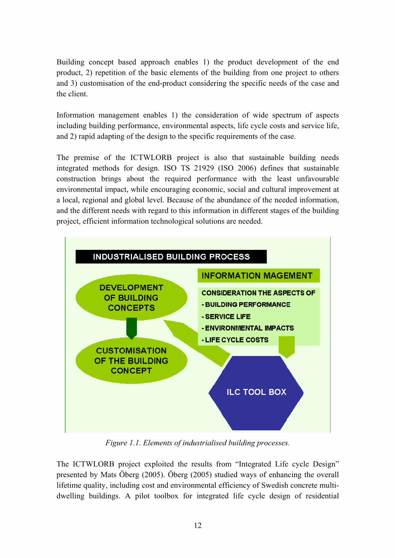
The premise of the ICTWLORB project is also that sustainable building needs integrated methods for design. ISO TS 21929 (ISO 2006) defines that sustainable construction brings about the required performance with the least unfavourable environmental impact, while encouraging economic, social and cultural improvement at a local, regional and global level. Because of the abundance of the needed information, and the different needs with regard to this information in different stages of the building project, efficient information technological solutions are needed.
Figure 1.1. Elements of industrialised building processes.
The ICTWLORB project exploited the results from �Integrated Life cycle Design� presented by Mats Öberg (2005). Öberg (2005) studied ways of enhancing the overall lifetime quality, including cost and environmental efficiency of Swedish concrete multi-dwelling buildings. A pilot toolbox for integrated life cycle design of residential

13
buildings was developed and tested. Öberg (2005) concluded that integrated life-cycle design may enhance the lifetime quality and cost effectiveness of buildings. The life cycle assessments tools and data are available and calculations can be done with reasonable effort giving reliable results.
The ICTWLORB project defined the following roles the different actors (Table 1.1).
Table 1.1. Roles of different actors in an industrialised building process.
(Contractor as a role of) Developer
Defines the purpose and the main aspects of the concept. The main aspects include the required building performance and lice-cycle performance profile. The developer also defines the freedom of the client to state client-specific requirements. Collects and maintains product information databases and tools that enable the LCA, LCC and service life assessments of individual solutions.
Client Defines the client specific requirements with regard to building performance and life cycle performance in the limits made possible.
Designer Designs the building solutions that fulfil the stated requirements and makes use of the product information data bases and tools in order to show the LCA, LCA and service life results of the solutions.
Materialproducer Delivers components or building systems according to the properties specified by the concept. Responsible to update product information data bases and to handle the information as specified by the developer.
Contractor Constructs the buildings according to the design. Collects the building specific care and maintenance instruction with help of product information databases.
Tenant Uses the building and realises the care and maintenance in accordance with the stated care and maintenance instructions.
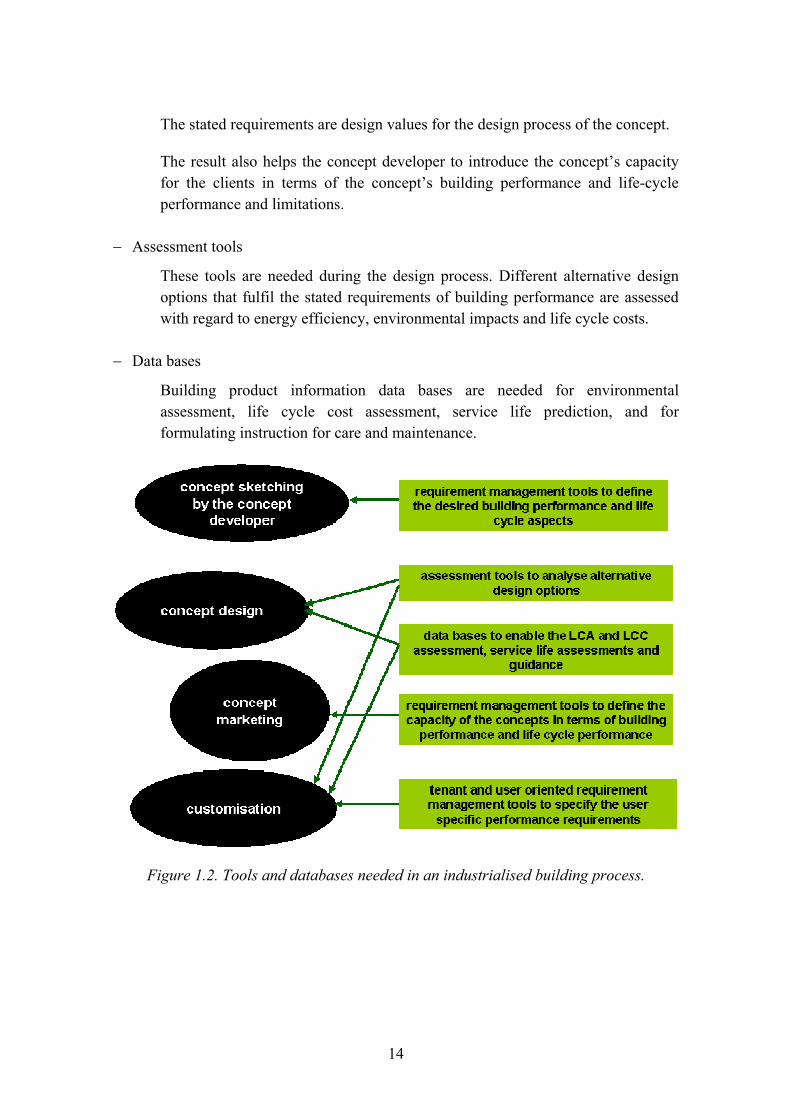
The ICTWLORB project collected and tested tools for the management of building performance and life cycle performance in an industrialised building process. The focus of the project was dwelling buildings in Sweden and Finland. The starting of the project was that the following tools are needed (Figure 1.2):
− Requirement setting tools to determine the desired building performance of the concept
These tools are needed in the original stages of the concept development. The developer defines the performance profile of the concept and the range of the performance profile.
− Requirement setting tools to determine the desired life cycle performance of the concept
These tools are needed in the original stages of the concept development. The developer defines limit values for the concept in terms of energy efficiency, environmental impacts, life-cycle costs and service life.
14
The stated requirements are design values for the design process of the concept.
The result also helps the concept developer to introduce the concept�s capacity for the clients in terms of the concept�s building performance and life-cycle performance and limitations.
− Assessment tools
These tools are needed during the design process. Different alternative design options that fulfil the stated requirements of building performance are assessed with regard to energy efficiency, environmental impacts and life cycle costs.
− Data bases
Building product information data bases are needed for environmental assessment, life cycle cost assessment, service life prediction, and for formulating instruction for care and maintenance.
Figure 1.2. Tools and databases needed in an industrialised building process.
15
1.3 Life-cycle management of buildings from the viewpoint of industrialised building
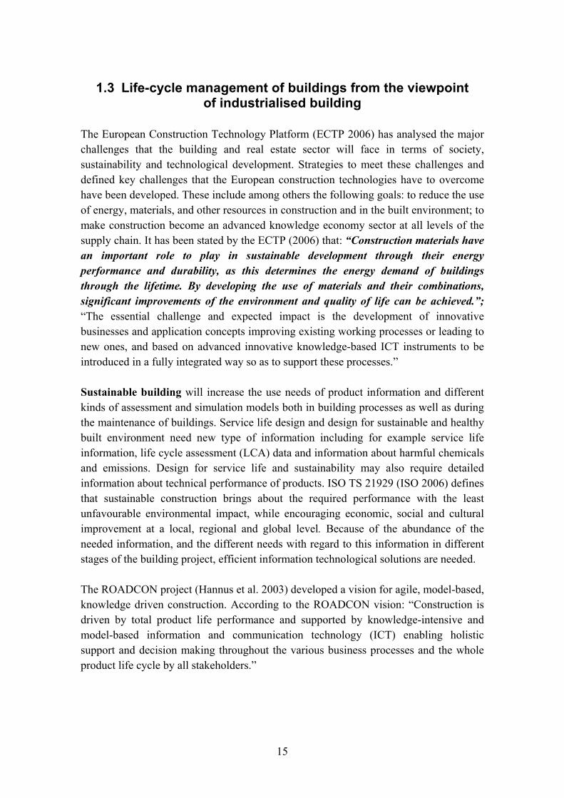
The European Construction Technology Platform (ECTP 2006) has analysed the major challenges that the building and real estate sector will face in terms of society, sustainability and technological development. Strategies to meet these challenges and defined key challenges that the European construction technologies have to overcome have been developed. These include among others the following goals: to reduce the use of energy, materials, and other resources in construction and in the built environment; to make construction become an advanced knowledge economy sector at all levels of the supply chain. It has been stated by the ECTP (2006) that: �Construction materials have an important role to play in sustainable development through their energy performance and durability, as this determines the energy demand of buildings through the lifetime. By developing the use of materials and their combinations, significant improvements of the environment and quality of life can be achieved.�; �The essential challenge and expected impact is the development of innovative businesses and application concepts improving existing working processes or leading to new ones, and based on advanced innovative knowledge-based ICT instruments to be introduced in a fully integrated way so as to support these processes.�
Sustainable building will increase the use needs of product information and different kinds of assessment and simulation models both in building processes as well as during the maintenance of buildings. Service life design and design for sustainable and healthy built environment need new type of information including for example service life information, life cycle assessment (LCA) data and information about harmful chemicals and emissions. Design for service life and sustainability may also require detailed information about technical performance of products. ISO TS 21929 (ISO 2006) defines that sustainable construction brings about the required performance with the least unfavourable environmental impact, while encouraging economic, social and cultural improvement at a local, regional and global level. Because of the abundance of the needed information, and the different needs with regard to this information in different stages of the building project, efficient information technological solutions are needed.
The ROADCON project (Hannus et al. 2003) developed a vision for agile, model-based, knowledge driven construction. According to the ROADCON vision: �Construction is driven by total product life performance and supported by knowledge-intensive and model-based information and communication technology (ICT) enabling holistic support and decision making throughout the various business processes and the whole product life cycle by all stakeholders.�
16
Traditional holistic optimisation of buildings from the point of view of life cycle costs, LCC, is done in several ways. Very often the influence on the various functions of the building, e.g., different sustainability or indoor climate, is not taken into consideration. With integrated life cycle design the characteristics and functions of the building are linked to the costs and influence of the building on the environment during its entire life-cycle.
Integrated life cycle design (ILCD) has been developed and systematised by Sarja (2002). The method has been further developed and applied in building project by Öberg (2005). In order to clarify the method, Öberg (2005) notes that the word integration �implies that components and systems should be designed with the understanding and respect of their interaction with other systems and the building as a whole�.
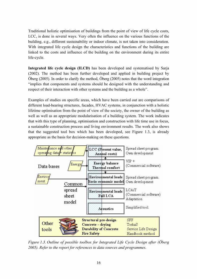
Examples of studies on specific areas, which have been carried out are comparisons of different load-bearing structures, facades, HVAC systems, in conjunction with a holistic lifetime optimisation from the point of view of the society, the owner of the building as well as well as an appropriate modularisation of a building system. The work indicates that with this type of planning, optimisation and construction with life time use in focus, a sustainable construction process and living environment results. The work also shows that the suggested tool box which has been developed, see Figure 1.3, is already appropriate as the basis for decision-making on these questions.
Figure 1.3. Outline of possible toolbox for Integrated Life Cycle Design after (Öberg 2005). Refer to the report for references to data sources and programmes.

17
A Building Information Model (BIM) implies that all information concerning a project, for example, for its design, is available digitally in one model. It is hoped that this model can be used, and be refined by all those involved and for all applications. The use of a BIM provides great advantages, for instance, by the fact that the interoperability of those involved and of the applications is complete. The disadvantages today are initially higher costs and the lack of the necessary open classifications and transmission formats. Today advanced ICT solutions, such as BIM, are thus in use only in complicated constructions such as extensive reconstructions, or in the case where the value of the enterprise is far greater than the value of the building, for example, in the case of the pharmaceutical industry buildings and constructions for certain other manufacturing industries. In these projects the design based on a model is directly profitable in the project.
In contrast to traditional multi-unit housing, where relatively uncomplicated technical solutions and installations are used, for advanced concept construction of multi-unit housing, it is practically a prerequisite that the design is undertaken digitally (BIM). This is also true for the collaboration with the manufacturing process and the enterprise systems.
Life cycle management and improved sustainability of buildings will require the development of building product information, depending on the used process. It will be necessary to develop the contents and supply of information as well as the models of exchange and use of this information in order to ensure the management of the required building performance and environmental impacts during the life cycle of buildings. The abundance of this information provided by suppliers and manufacturers and the different needs in different stages of the building process requires the development and use of new information technological solutions.
As mentioned before, in Europe there is a generally-held opinion that the building and real estate sectors must develop towards greater sustainability. Among construction firms, this is often undertaken under the concept of industrialised construction. Industrialised construction is an extremely wide concept, which covers the whole spectrum from improvements in the traditionally designed construction process to the development of concept-design based on experience from other industries, often the manufacturing industries.
For the development of the construction and housing sectors, it is advisable to start by defining the processes which are being used or are being aimed for.
Traditional construction can be described (Winch 2002) as �Concept to Order�, CtO, in which the customer initiates both the process and the product. With CtO each project is relatively independent of any previous one. This in often described as a relay race (Figure 1.4).

18
Programme Design Use Process/Project
Product
Maintenance
Logistics
Manufacture
Construction
Figure 1.4. A schematic diagram of the construction and maintenance of a traditional building project. Each project is unique, and the process and the product meet first on the construction site.
In recent years it has been found that this form of project involves extensive waste, which has been quantified by, among others, Josephsson and Saukkoriipi (2005). It should, however, be noted that his work considers only the construction process, and not the use of the building over its life cycle, which normally is dominant. An appreciation of the potentials has led over recent years to the development of the traditional building project. For instance, forms of purchasing in which the risks and possibilities (responsibilities and rights), are shared are now common, as are also the delivery of whole systems such as in load-bearing construction.
At the same time, an advanced type of concept-based construction has been developed, based on the manufacturing industry, which can be described as (Winch 2002) �Make to Order�, MtO, where the owner of the concept owns both the process and the product. In MtO all projects are based on the same knowledge and technology as previous projects. This process is often described as in Figure 1.5.

19
Product
Process
Project x1
Project x2
Project x3
Project y1
Project y2
Figure 1.5. A schematic diagram of construction and maintenance of a concept-based construction. (Revised from Lessing [2006].)
In recent years several areas of concept-based construction, which have attracted much attention, have been developed and come on the market. These concepts are focussed on specific segments, often flats with tenancy rights, but there are other specific concepts, and others are under discussion, for instance, offices and football arenas etc.
Since the processes used depend on aspects of the market, such as its size, demands of the customer, etc., both of the processes described above will exist parallel. In reality, most construction is already today carried out as a mix of the processes mentioned above. For example, most building material suppliers already today deliver systems and products that are manufactured according to MtO (Figure 1.5).
In Öberg (2005) ILCD is treated only for the traditional construction process. In the present project the focus has instead been on the utilization of ILCD in advanced concept-based construction, namely Skanska�s �ModernaHus�.
One of the hypotheses behind this project is that ILCD is applicable directly to an advanced concept-construction. In the early stages of a traditional construction project, only generic, superficial assessments can be made, on such characteristics as, for example, sustainability, energy consumption, indoor climate and sound classification. Final assessments can not be made until the entire building has been designed, which is a (too) late stage for both possibly necessary alterations, but above all because insufficient time will be available to make a holistic optimisation. For an advanced
Building projects

20
concept-construction a detailed holistic optimisation is undertaken of the overall product development of the concept. For each project which is made with the concept, it is necessary to make only limited assessments based on the configurations made for each specific project. This is called �Integrated Life Cycle -Configuration� (ILC-C) in the report.
Customer-value is one of the important driving forces behind the transformation of the building and real estate sectors. This is true in particular for the construction and housing market previously supported by state funding. This project is focussed on advanced concept-based constructions for multi-unit housing. The forms for renting and owning apartments are different in different countries. In Sweden, for instance, co-operative tenant-ownership flats are common, but are rare in other countries, where different types of owner flats are the norm. In many countries rented society-owned apartment houses exist only in the form of �social housing�, while rented society-owned apartment housing dominates throughout the Swedish rented apartment housing market. In the design of an apartment building, each individual apartment is often entirely dependent on the design of the whole building, which may concern such disparate factors as its exterior architecture and the heating and ventilation systems. Both of these factors imply that the customer for an apartment house in this project is defined as the owner of the property. In an advanced concept-construction the customer-value is utilized and developed both in the continuing product development and in the the specific configuration of each project.
With help of product modelling it is possible to efficiently handle more product information than ever. IFC-standards (IAI) have been developed in international co-operation in order to harmonise building information representation and its transfer. The target is that all information in building sector could be easily exchanged from one actor to another, within design, and between different stages during the building lifecycle. Even though IFC is meant to cover all the building life cycle phases, it is so far concentrated mostly on the generic information used in the design phase.
On the other hand, many players in Architectural-Engineering-Construction (AEC) community have been creating their computational systems and estimation programs using data structures that are not compatible with the IFC standard. These applications can use product-specific information, i.e. information produced by the suppliers or vendors of the actual products used in the construction. However, they are essentially based on manual data input where the user reads data from suppliers brochures and types the data manually via the application�s user interface.
When more and precise product information can be used in building design, purchase, assembling, care and maintenance processes, the building quality could be further
21
improved. Since the product-specific information is poorly standardised this information cannot be totally utilised because expensive and error-prone manual phases are needed.
References
ECTP. 2006. The European Construction Technology Platform (ECTP). http://www.ectp.org/default.asp.
Hannus, M. et al. 2003. Construction ICT Roadmap. IST-2001-37278 ROADCON. 77 p. http://cic.vtt.fi/projects/roadcon/docs/roadcon_d52.pdf.
IAI. International alliance for interoperability. http://www.iai-international.org/index.html.
ISO. 2006. ISO TS 21929. Building Construction � Sustainability in Building Construction � Sustainability Indicators. Part 1 � Framework for the development of indicators for buildings.
Josephsson, P.-E. & Saukkoriipi, L. 2005. Slöseri i byggprojekt. Behov av förändrat synsätt. Fou-Väst Rapport 0507. Göteborg: Sveriges Byggindustrier.
Lessing, J. 2006. Industrialised House-Building. Lund: Lund Institute of Technology.
Sarja, A. 2002. Integrated Lifecycle Design of Structures. London and New York: Spon Press.
Winch, G. 2002. Models of manufacturing and the construction process: the genesis of re-engineering construction. Building Research and Information, Vol. 31, No. 2, 1 January 2002, pp. 107�118.
Öberg, M. 2005. Integrated life cycle design. Application to Swedish concrete multi-dwelling buildings. Report TVBM-1022. Lund.
22
Chapter 2
Author Tarja Häkkinen
Contents
2. Life cycle methodology for buildings � regulatory and methodological framework .....23 2.1 Introduction ......................................................................................................23 2.2 Life cycle approach in the context of sustainable development
strategies of the EU ..........................................................................................24 2.3 Building regulatory and standardisation framework for the life cycle
management of buildings .................................................................................25 2.3.1 Construction Product Directive............................................................26 2.3.2 Harmful chemicals and health effects ..................................................26 2.3.3 Energy Performance of Buildings........................................................27 2.3.4 Standards for life-cycle assessment and service life design of buildings.... 27 2.3.5 Life Cycle Assessment (LCA) .............................................................29 2.3.6 Life cycle costing (LCC)......................................................................29
2.4 Methodologies for life cycle management of buildings ...................................31 2.4.1 Sustainability indicators for building ...................................................31 2.4.2 National environmental assessment and classification
methods for buildings and building products.......................................32 2.4.3 Methodologies for requirement management ......................................35 2.4.4 Methodologies for service life management ........................................36
2.5 Usability and restrictions of life cycle management methodologies................39 2.5.1 Requirement setting .............................................................................40 2.5.2 Design for required performance .........................................................40 2.5.3 Declaration ...........................................................................................41 2.5.4 Industrialised building processes .........................................................42
References..................................................................................................................42

23
2. Life cycle methodology for buildings � regulatory and methodological framework
2.1 Introduction
This chapter describes the basics of life-cycle methodology for residential buildings. Life-cycle management of buildings is here defined to include the following aspects: building performance and service life, environmental impacts, and life cycle costs. The process should include the following three main steps:
− defining performance and life cycle requirements − design for required performance, service life, life cycle impacts, and life cycle costs − assessment of conformity with the defined requirements.
Integrated life-cycle design should be provided by methods which support requirement setting and concept definition, design for desired building performance and life cycle performance and the assessment of the conformity of the design with reference to the stated requirements. As described in the previous chapter (Introduction), in an industrialised building process the design is produced in two phases: 1) development of the concept, 2) customisation of the concept for individual clients.
This chapter discusses the congruence of the life cycle methodologies with the European policy strategies, introduces the regulatory and standardisation framework of life cycle management of buildings, and discusses the availability of methods and tools.
Integrated life cycle methodology of buildings combines the approaches of performance based building and life cycle management (Figure 2.1). The performance approach is the practice of thinking and working in terms of ends rather than means (CIB 1982). The �ends� usually relate to technical attributes of a building, whether expressed as a high-level goal (e.g. safety), functional requirement (e.g. structural stability) or specific performance requirement (e.g. the load-carrying capacity of a column should be greater than the vertical load it supports) (Bakens et al. 2005). Performance approach is a key element in sustainable construction. As the performance approach starts off with an expression of what is expected from a building in terms of functionality, the identification of performance requirements can perform as an anchor in other elements of sustainable construction (Trinius 2005). Service life is defined to end when the building or parts of it no longer meet or exceed established performance requirements, and environmental comparisons and life-cycle costs assessments should be done with reference to equivalent functional units.

24
Öberg (2005) studied ways of enhancing the overall lifetime quality, including cost and environmental efficiency of Swedish concrete multi-dwelling buildings. A pilot toolbox for integrated life cycle design of residential buildings was developed and tested. Öberg (2005) concluded that integrated life-cycle design enhance the lifetime quality and cost effectiveness of buildings. The life cycle assessments tools and data are available and calculations can be done with reasonable effort giving reliable results.
Figure 2.1. Integrated life cycle methodology of buildings combines the approaches of performance based building and life cycle management.
2.2 Life cycle approach in the context of sustainable development strategies of the EU
The implementation of the principles of sustainable development is a fundamental goal of EU policies. The European Council of June 2006 adopted a comprehensive renewed Sustainable Development Strategy for an enlarged EU (EU 2006). The renewed strategy recognises the need to gradually change the current unsustainable consumption and production patterns and move towards a better integrated approach in policy-making. The overall aim of the renewed EU Sustainable Development Strategy is to identify and develop actions, which enable the EU to achieve continuous improvement of quality of life both for current and for future generations, through the creation of sustainable communities. Sustainable communities should be able to manage and use resources

25
efficiently and to make use of the innovation potential of the economy, ensuring prosperity, environmental protection and social cohesion.
In principle, the emphasis on life cycle approach issues from the principles of sustainable development. As stated in the renewed Sustainable Development Strategy for an enlarged EU (EU 2006): �Sustainable Development stands for meeting the needs of present generations without jeopardizing the needs of futures generations � a better quality of life for everyone, now and for generations to come. It offers a vision of progress that integrates immediate and longer-term needs, local and global needs, and regards social, economic and environmental needs as inseparable and interdependent components of human progress.� The adoption of life cycle approach as a basic principle for sustainable building methodologies is consistent with the EU policies on sustainable development.
Integrated product policy has a clear role to play in contributing to sustainable development. All products and services have environmental impacts during their production, use and/or disposal. IPP (2003) emphasises that the challenge is to combine improving life styles and well-being with environmental protection. It is important to ensure that environmental impacts are addressed throughout the life-cycle in an integrated way. It is also important that environmental impacts are addressed at the point of life-cycle where they will best and most cost-effectively reduce the overall environmental impacts and resource use.
LC guides have been developed nationally and in international level for life cycle assessment and declaration of building products, services and buildings. The general principles on life cycle assessment of products and services have been agreed upon and made public with help of standardisation. There are international standards available on the formats, contents and processes of environmental declarations of products. In addition to general methodologies, applied methods for building products have been standardised by ISO. There is also a European process going on, which aims at the development of harmonised life-cycle standards for buildings and building products as described in the next section of this chapter.
2.3 Building regulatory and standardisation framework for the life cycle management of buildings
The life cycle approach can be distinguished in the two essential directives, which direct the building product and energy regulations of building, namely CPD and EPD; both of these emphasise the importance of use phase of buildings.

26
2.3.1 Construction Product Directive
The European Union adopted the Construction Product Directive (CPD 1988) in 1988. The Directive aims to complete the internal market for construction products through removal of barriers for trade by means of technical harmonisation.
The CPD defines the so-called essential requirements concerning safety and health aspects in construction works. According to the Annex 1 �the products must be suitable for construction works which (as a whole and in their separate parts) are fit for their intended use, account being taken of economy, and in this connection satisfy the essential requirements where the works are subject to regulations containing such requirements. Such requirements must, subject to normal maintenance, be satisfied for an economically reasonable working life�. In contrast to earlier directives, the essential requirements stated in the CPD, are directed to construction works instead of building products. Therefore interpretative documents have been drawn up to the essential requirements. These should give concrete form to the essential requirements.
The essential requirement Number 3 is titled as �Hygiene, Health and the Environment�. According to the interpretative document concerning the essential requirement Number 3, the environmental impact of building products shall be considered in all stages of life cycle including the extraction of raw materials, manufacture, construction, use, demolition, final disposal and reuse. However, being adapted to the limits of the CPD, the interpretative document is now related to the product �in use�. For the present, the CPD mainly deals with the health issues, but the European Commission has noticed the need to take into account the environmental aspects and the need to provide the products with comprehensive environmental information. The development of the European standards on environmental performance of building products is the first step towards this.
2.3.2 Harmful chemicals and health effects
The second generation of harmonised product standards under the Construction Products Directive (CPD) requires harmonised test methods for the release or emission of dangerous substances to satisfy the requirements of Essential Requirement 3 of the CPD. The European Commission has issued Mandate M/366 to CEN. The scope of the TC 351 is to develop horizontal standardised assessment methods for harmonised approaches relating to the release of regulated dangerous substances under the Construction Products Directive taking into account the intended conditions of use of the product. It addresses emission to indoor air, and release to soil, surface water and ground water (CEN 2005). The objective of CEN/TC 351 is to develop the standards,
27
finalise the validation process for the standards and provide the Technical Reports mentioned in Mandate M/366.
2.3.3 Energy Performance of Buildings
The European Directive 2002/91/EC on Energy Performance of Buildings (EPB 2002) came into force 16 December 2002 in order to be implemented in the legislation of the member states in 2006. Four main elements define the requirements that were needed to be integrated into national legislation:
− establishment of a methodology for an integrated calculation of the overall energy performance of buildings
− definition of minimum energy efficiency requirements per member state based on this methodology
− energy efficiency certification of new and existing buildings
− regular inspection of heating and air conditioning systems.
On the basis of the EC standardisation mandate M/330 EN CEN is developing methodologies for the calculation of the energy uses and losses for heating and cooling, ventilation, domestic hot water, lighting, natural lighting, passive solar systems, passive cooling, position and orientation, automation and controls of buildings, and auxiliary installations necessary for maintaining a comfortable indoor environment of buildings.
Obviously, the EPB directive emphasises the life-cycle approach. The directive highlights the consideration of use phase of buildings and aims at supporting owners and users of buildings to take into account the expected energy flows and related life cycle costs when making choices.
2.3.4 Standards for life-cycle assessment and service life design of buildings
There is an active process going on aiming at the formulation of international and European standards for the assessment and declaration methods of environmental aspects of buildings and building products.
CEN/TC 350 will develop voluntary horizontal standardised methods for the assessment of the environmental performance of new and existing buildings and for standards for the environmental product declaration of construction products, in the framework of the integrated performance of buildings. The becoming standards will be applicable

28
(horizontal) and relevant for the assessment of buildings over its life cycle. The results from the standards mandated by the M/330 (energy performance directive) are integrated into the assessment of the environmental performance of buildings in the framework of integrated performance of buildings.
The standards that will be developed by CEN/TC 350 will describe a harmonized methodology for the assessment of environmental performance of buildings and life cycle cost performance of buildings as well as the quantifiable performance aspects of health and comfort of buildings. The agreed basic principles for the development of the becoming standards support the EU environmental policies, such as Integrated Product Policy (IPP 2003), the Sixth Community Environment Action Programme (6EAP) (Sixth EAP 2002) and several thematic strategies derived from the 6EAP.
The stakeholders in the building sector should come from all sectors of the construction industry and building management and include building owners and users, investors, insurance companies as well as manufacturers, designers and contractors.
ISO/TC 59 �Building construction� / SC 17 �Sustainability in building construction� makes standardisation in the field of sustainability of the built environment. The environmental, economic, and social aspects of sustainability are included as appropriate. The work is carried out by four working groups:
− WG 1: General Principles and Terminology − WG 2: Sustainability Indicators − WG 3: Environmental Declarations of Building Products − WG 4: Framework for Assessment of Environmental Performance of Buildings.
The work of WG 3 has resulted in the development of ISO/DIS 21930 (Building construction � Sustainability in building construction � Environmental declaration of building products) (ISO 2006a). ISO/DIS 21930 provides the principles and requirements for conducting Type III environmental declarations of building products. It gives guidelines for the development and implementation of such declarations based on the Life Cycle Assessment, LCA. Thus ISO/DIS 21930 complements the general provisions for such declarations contained in ISO 14025 (ISO 2006b). ISO/DIS 21930 also provides a general framework for Product Category Rules, PCR, as defined in ISO 14025, for Environmental Product Declarations of building products.
ISO has also leaded the process of developing standards for service life planning. ISO 15686-1 (ISO 2000), ISO 15686-2 (ISO 2001) and ISO/DIS 15686-8.2 (ISO 2006c) give general principles for service life planning, describe service life prediction procedures and give guidelines for reference service life. Standard ISO 15686-1 presents
29
a basic methodology in the area of service life design, but the methodology requires considerable knowledge about the age and degradation of components and materials.
2.3.5 Life Cycle Assessment (LCA)
LCA is a technique for assessing the environmental aspects and potential impacts with a product by (ISO 2006d):
− compiling an inventory of relevant inputs and outputs of a product system
− evaluating the potential environmental impacts associated with those inputs and outputs
− interpreting the results of the inventory analysis and impact assessment phases in relation to the objectives of the study.
ISO standards 14040 (ISO 2006d) and 14044 (ISO 2006e) describe the methodology and give principles and guidelines for Life Cycle Assessment. LCA studies the environmental aspects and potential impacts throughout a product�s life from raw material acquisition through production, use and disposal. According to ISO 14040, LCA can assist in
− identifying opportunities to improve the environmental aspects of products at various points in their life cycle
− decision-making in industry, governmental or non-governmental organisations
− selection of relevant indicators of environmental performance, including measurement techniques
− marketing (e.g. environmental claim, eco-labelling scheme, including environmental product declaration).
As sated by Cole (2004) the notion of life cycle assessment has been generally accepted within the environmental research community as the only legitimate basis on which to compare alternative products and services; the approach is firmly adopted for the European assessment tools.
2.3.6 Life cycle costing (LCC)
Life cycle costing (LCC) is a technique for estimating the cost of whole buildings, systems and/or building components and materials, and for monitoring the occurred throughout the lifecycle. The technique can assist decision-making in building investment projects. LCC is used to evaluate the cost performance of a building
30
throughout its lifecycle, including acquisition, development, operation, management, repair, disposal and decommissioning. Although the basic principles of LCC are widely agreed upon and known, LCC is not commonly applied in Europe in practice.
ISO/DIS 15686-5 (ISO 2006f) is currently in preparation. This part of ISO 15686 aims at providing the procedures for performing LCC analyses of building and constructed assets and their parts, including cost or cash flows. The main content covers principles of life-cycle costing, instructions for LCC assessment with reference to
− design options/alternatives − investment options − decision variables − uncertainty and risk.
Nordtest standard (LCC for building trade (NORDTEST 2001), is a Nordic classification system for lifecycle costing. It doesn�t differ much from ISO15686-5 (Table 2.1). However it aims to increase knowledge and competence on LCC as a consequence of increasing demand and service life planning. The expressions and mathematics of Life Cycle costing have been developed nationally in different countries. The basic principles adopted by those standards are quite alike. However, practical use of life cycle costing methodologies is not quite clarified (Häkkinen & Pulakka 2007).
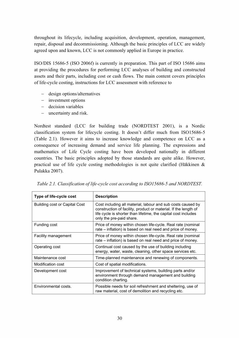
Table 2.1. Classification of life-cycle cost according to ISO15686-5 and NORDTEST.
Type of life-cycle cost Description
Building cost or Capital Cost Cost including all material, labour and sub costs caused by construction of facility, product or material. If the length of life cycle is shorter than lifetime, the capital cost includes only the pre-paid share.
Funding cost Price of money within chosen life-cycle. Real rate (nominal rate � inflation) is based on real need and price of money.
Facility management Price of money within chosen life-cycle. Real rate (nominal rate � inflation) is based on real need and price of money.
Operating cost Continual cost caused by the use of building including energy, water, waste, cleaning, other space services etc.
Maintenance cost Time-planned maintenance and renewing of components. Modification cost Cost of spatial modifications. Development cost Improvement of technical systems, building parts and/or
environment through demand management and building condition charting.
Environmental costs. Possible needs for soil refreshment and sheltering, use of raw material, cost of demolition and recycling etc.

31
2.4 Methodologies for life cycle management of buildings
2.4.1 Sustainability indicators for building
ISO TS 21929 (ISO 2006g) defines a framework for sustainability indicators of buildings. The framework is based on the premise that sustainable construction brings about the required performance with the least unfavourable environmental impact, while encouraging economic, social and cultural improvement at a local, regional and global level.
Environmental indicators address environmental aspects in terms of environmental loadings or impacts assessed on the basis of life cycle inventory or assessment. Environmental loadings are the use of resources and the production of waste, odours, noise and harmful emissions to land, water and air. However, consequential environmental indicators are also needed and used in requirements setting, design and selection of products for sustainable building. Consequential environmental indicators express environmental impacts in terms of building performance or location either quantitatively or qualitatively. These kinds of indicators have been developed for cities, built environment, buildings and other constructive assets and building products in various research projects like in the European CRISP (Häkkinen et al. 2002) and TISSUE (2004) projects.
According to ISO TS 21929 the following economic flows are related to the life cycle of a building:
− investment: site, design, product manufacturing, construction − use: energy consumption, water consumption, waste management etc. − maintenance and repair − deconstruction and waste treatment − development of the economic value of a building − revenue generated by the building and its services.
The economic indicators indicate monetary flows connected to the building life cycle. Social indicators of buildings are used to describe how buildings interact with issues of concern related to sustainability at the community level. Community level issues that may be relevant are for example urban sprawl, mixed land use, access to basic, availability of green and open space, attractiveness of city centres, development of brown-fields, availability of housing, social segregation, cultural quality and protection of cultural heritage, safety, noise and air quality. Social aspects can also be addressed on the building level like for example (ISO 2006a):
− quality of buildings as a place to live and work − building-related effects on health and safety of users
32
− barrier-free use of buildings − access to services needed by users of a building − user satisfaction − architectural quality of buildings − protection of cultural heritage.
In the discussions on sustainable building the link of sustainable building with building performance has been emphasised lately (Trinius & Sjöström 2005). Though environmental impacts and life cycle costs indicate aspects of sustainability, the quantifying is meaningless without a common reference. When comparing different design options, performance aspects are the underlying factor. Building performance is gaining stronger consideration in the connection of sustainable building, and thus also the management of building performance can be seen as an important part of sustainable building process.
2.4.2 National environmental assessment and classification methods for buildings and building products
In addition to internationally agreed standards and guidelines, there are a number of national and specific methodologies for integrated life-cycle management of buildings. These methodologies are mainly for the assessment and classification of buildings. There are a number of methodologies for evaluating buildings after they are designed, but as stated by Kohler and Lützkendorf (2002) the problem is creating an appropriate tool for the design team to use during the design process to create sustainable buildings.
The researches and practitioners together have developed environmental assessment and classification systems for buildings in a number of European countries. These tools provide a wide coverage of environmental, economic and building performance issues, which are deemed to be relevant to sustainability. Normally certificates or labels are given on the basis of assessment; some require external auditors. These tools have been developed for the following purposes: 1) target setting, 2) identifying essential sustainability issues, 3) assessing and classification of buildings and using the achieved certificates or labels in marketing.
For example VTT together with the actors of the Finnish building and real estate sector has developed national methods for environmental management of buildings and building products. These include the following methods and tools:
− the EKA method for the environmental assessment and environmental declarations of building products (Häkkinen et al. 2004)
33
− the environmental classification method for buildings PromisE (Table 2.2) (described in Huovila & Häkkinen 2005)
− the environmental assessment and life cycle cost assessment tool to support consideration of life cycle aspects in building design (BECOST 2005)
− building performance requirement management tool, EcoProP, to support requirement setting (EcoProP 2006).
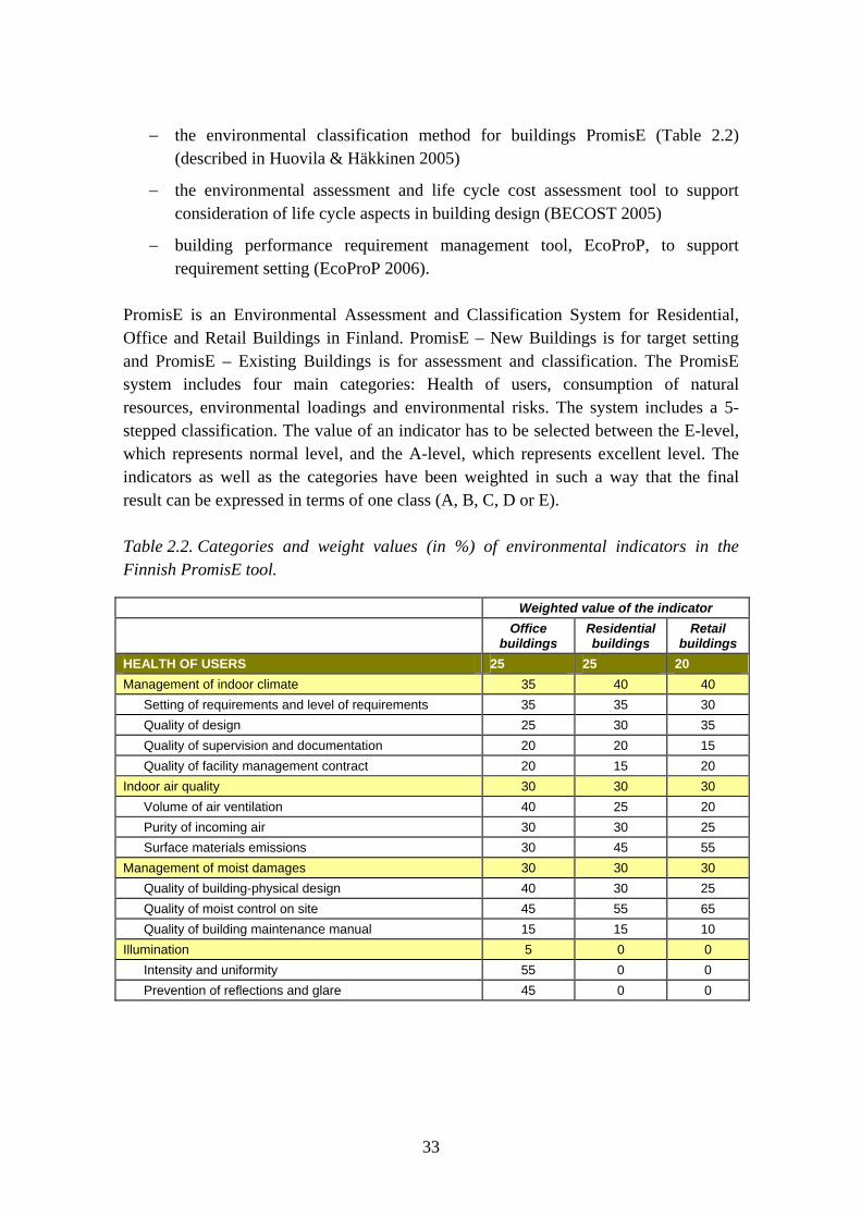
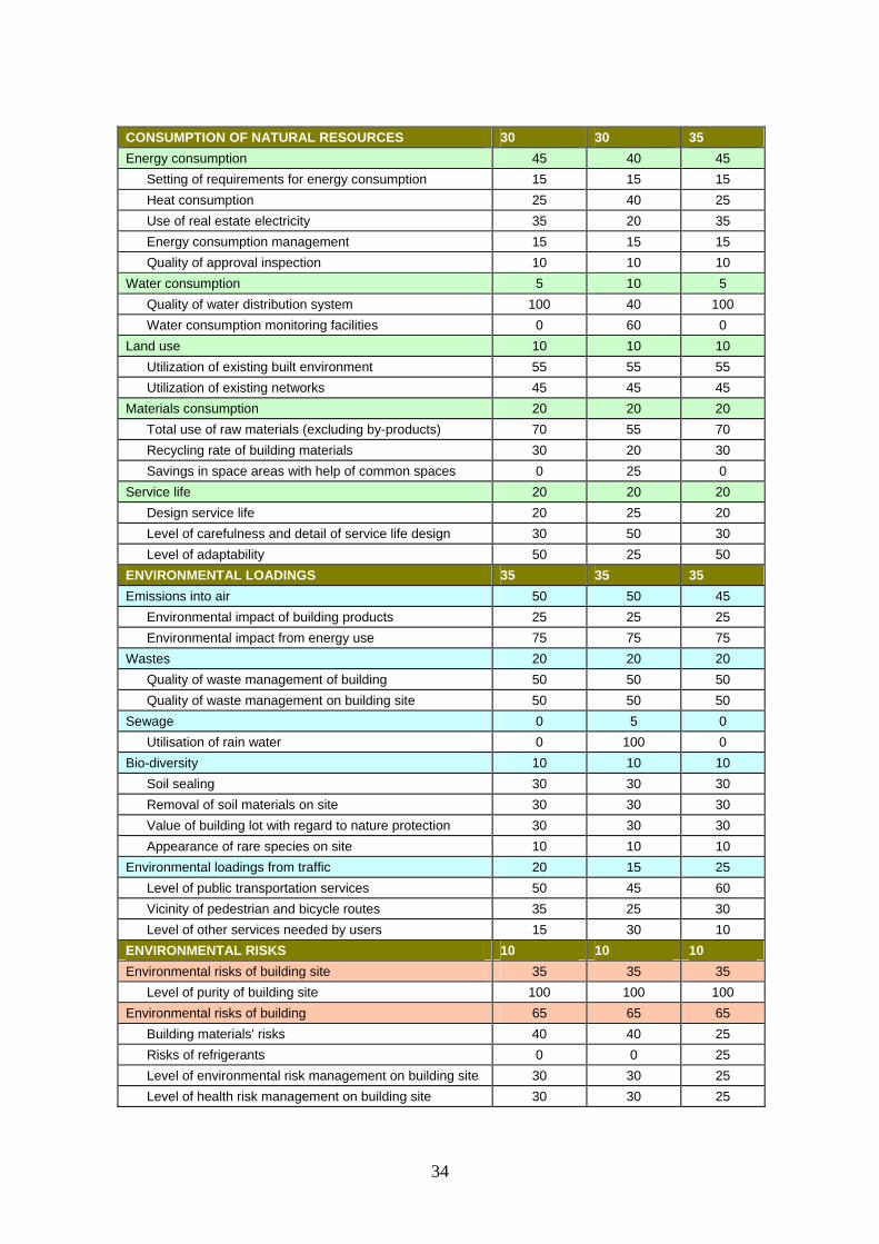
PromisE is an Environmental Assessment and Classification System for Residential, Office and Retail Buildings in Finland. PromisE – New Buildings is for target setting and PromisE – Existing Buildings is for assessment and classification. The PromisE system includes four main categories: Health of users, consumption of natural resources, environmental loadings and environmental risks. The system includes a 5-stepped classification. The value of an indicator has to be selected between the E-level, which represents normal level, and the A-level, which represents excellent level. The indicators as well as the categories have been weighted in such a way that the final result can be expressed in terms of one class (A, B, C, D or E).
Table 2.2. Categories and weight values (in %) of environmental indicators in the Finnish PromisE tool.
Weighted value of the indicator Office
buildings Residential buildings
Retail buildings
HEALTH OF USERS 25 25 20
Management of indoor climate 35 40 40
Setting of requirements and level of requirements 35 35 30
Quality of design 25 30 35
Quality of supervision and documentation 20 20 15
Quality of facility management contract 20 15 20
Indoor air quality 30 30 30
Volume of air ventilation 40 25 20
Purity of incoming air 30 30 25
Surface materials emissions 30 45 55
Management of moist damages 30 30 30
Quality of building-physical design 40 30 25
Quality of moist control on site 45 55 65
Quality of building maintenance manual 15 15 10
Illumination 5 0 0
Intensity and uniformity 55 0 0
Prevention of reflections and glare 45 0 0
34
CONSUMPTION OF NATURAL RESOURCES 30 30 35
Energy consumption 45 40 45
Setting of requirements for energy consumption 15 15 15
Heat consumption 25 40 25
Use of real estate electricity 35 20 35
Energy consumption management 15 15 15
Quality of approval inspection 10 10 10
Water consumption 5 10 5
Quality of water distribution system 100 40 100
Water consumption monitoring facilities 0 60 0
Land use 10 10 10
Utilization of existing built environment 55 55 55
Utilization of existing networks 45 45 45
Materials consumption 20 20 20
Total use of raw materials (excluding by-products) 70 55 70
Recycling rate of building materials 30 20 30
Savings in space areas with help of common spaces 0 25 0
Service life 20 20 20
Design service life 20 25 20
Level of carefulness and detail of service life design 30 50 30
Level of adaptability 50 25 50
ENVIRONMENTAL LOADINGS 35 35 35
Emissions into air 50 50 45
Environmental impact of building products 25 25 25
Environmental impact from energy use 75 75 75
Wastes 20 20 20
Quality of waste management of building 50 50 50
Quality of waste management on building site 50 50 50
Sewage 0 5 0
Utilisation of rain water 0 100 0
Bio-diversity 10 10 10
Soil sealing 30 30 30
Removal of soil materials on site 30 30 30
Value of building lot with regard to nature protection 30 30 30
Appearance of rare species on site 10 10 10
Environmental loadings from traffic 20 15 25
Level of public transportation services 50 45 60
Vicinity of pedestrian and bicycle routes 35 25 30
Level of other services needed by users 15 30 10
ENVIRONMENTAL RISKS 10 10 10
Environmental risks of building site 35 35 35
Level of purity of building site 100 100 100
Environmental risks of building 65 65 65
Building materials' risks 40 40 25
Risks of refrigerants 0 0 25
Level of environmental risk management on building site 30 30 25
Level of health risk management on building site 30 30 25
35
EKA is a Finnish national, voluntary method for environmental assessment of building products. VTT formulated the method on the request by The Confederation of Finnish Construction Industries RT. The method describes the principles that should be followed in the environmental assessment of building products and introduces the format of environmental declarations. The procedure for environmental assessment and declaration of building products includes the following issues:
− principles for data collection and data handling
− generic environmental profiles for energy and transportation
− the declaration format
− procedure of environmental assessment; auditing, approval and publication of declarations
− principles that one should follow when using the environmental profiles of building products within building design and environmental assessment of buildings.
Corresponding national methods and tools have been developed in a number of countries as presented for example in the Sustainable Building Conference in Tokyo (see Cole et al. 2005). The connective features include the life-cycle approach and making use of sustainability indicators for the classification of buildings.
2.4.3 Methodologies for requirement management
Efficient requirement management in construction projects needs requirements systematics and tools for information management. Requirement systematics enables the client to consider the various aspects of a building, to choose the relevant requirements and to set requirement levels. Requirement management tools are important in order to support requirement setting, to ensure the flow of information for all relevant actors and to ensure the checking and fulfilment of the stated requirements.
Requirement management may focus on different kinds of spatial, usability, technical, functional, and life-cycle aspects of buildings. However, requirement management is especially challenging in performance based building. Performance is concerned with what a building or building product is required to do and not with prescribing how it is to be constructed as stated in CIB (1982).
In current practice, client requirements are typically recorded in a building programme and those cover various aspects from the overall goals, planned activities and spatial needs to very detailed material and performance requirements. Building programme is used as the starting point for the design process, but it is not up-dated and it is not used

36
as a steering document against which the design is continuously checked. As a consequence, this can lead to a design solution that may no longer meet the original requirements. Kiviniemi (2005) has described requirements model specification. According to Kiviniemi the requirements model specification enables implementation of requirements management applications linked to building product models, and the use of such applications can improve the management of detailed client requirements in the building process.
EcoProP is a software tool for the systematic management of building project requirements (Huovila & Porkka 2005). The EcoProP software helps to fulfil customer requirements and expectations by describing the properties of the final product using a hierarchy of performance requirements and different performance �levels�. The technical solutions can then be designed on the basis of the specified performance requirements.
EcoProP comprises a database of performance requirements and an easy-to-use interface to the database. The user can select from one to five pre-set performance levels for each requirement and then add their own comments. Based on the specified performance requirements, the user can print out a project brief in HTML or Word format. The reports can be customised for relevant stakeholders. It is possible to also have a report only on certain performance properties (such as adaptability) or a thematic report such as �health-related� requirements. The application provides estimates of the life cycle costs of the building. This analysis is based on the cost factors associated with different performance levels and the baseline information of the project. The user can use NPV and Annuity methods in the calculation and the discount rate and timeframe can be changed. Additionally, the environmental �costs� due to the operational energy consumption can be estimated.
The first step for setting requirements in EcoProP is to start a new project. The user then selects the correct requirement definition set, e.g. office building or apartment building, and then adds the baseline information on the project, e.g. investment cost, operational cost, energy unit cost, size of the building etc. It is also possible to add different scenarios for each project. The user then selects the appropriate performance level for each relevant requirement. A requirement profile can then be created on the basis of the average of the normalised performance levels for each requirement.
2.4.4 Methodologies for service life management
The construction Product directive (CPD 1988) formulates: �The product must be suitable for construction works which are fit for their intended use, account being taken of economy, and in this connection satisfy the following essential requirements� Such
37
requirements must, subject to normal maintenance, be satisfied for an economically reasonable working life.� On the basis of this, service life design should aim at required performance and the stability economical maintenance of this performance during the design life. Thus service life design should not only be separate �durability design�, but design for required performance considering the time aspect.
Service life design is an inseparable part of eco-efficient building process. In an effective process
− building product manufacturer is responsible for providing good quality service life information for his products and ensuring that the information is available for those who need it within design and construction.
− within a building project, the client states the requirements having an objective that the building fulfils the business and use based needs. The designer supports the client�s setting requirements helping him to express the requirements in terms of performance and service life requirements of the building.
− the designer designs the space and technical solutions of the building in such a way that the building fulfils the stated requirements. On the basis of the service life requirement stated for the building, the designer defines the service life requirements for building parts. The designer creates the design documents and makes the product selections in general level. The designer uses the product specific service-life information as reference information, with help of which he can specify requirements for the building phase. The technical properties, service life as well as its preconditions are dealt with as required quality in the design documents.
− in the building stage, the quality requirements stated for products and/or building parts should be taken into account. The product-specific service-life information should be included to the building-specific information. The contractor takes care that the product specific service life information forms the basis of the care and maintenance manual of the building.
Standard ISO 15686-1 presents a valuable basic methodology in the area of service life design, but the methodology requires considerable knowledge about the degradation of components and materials (Marteinsson 2003). The service life and environmental assessment and prediction methodologies standardised by ISO provide a framework for the assessment procedure. Tools and practical guidelines have to be developed to make the methods easy to use for practitioners.
The ISO 15686 series identifies procedures for the linkage with other design tools such as environmental and lice-cycle cost assessments. With the concept of service life planning, an integrated planning for consideration of technical, economic, and
38
environmental items of concern has been developed (Trinius & Sjöström 2005). However, the application of the integrated planning concept in service life planning still requires routines for the establishment of performance requirements over time. Additionally, further work is needed to relate lower and higher system-level requirements to each other.
Service life prediction methods have been developed for construction products which are exposed to weather conditions (for example Shohet et al. [2002] and ENNUS [2006]). There is a growing awareness worldwide of the importance of the maintenance of constructed facilities as shown by Shohet et al. (2002). Among of the most important parameters affecting the efficiency of maintenance management are the precision and the reliability of the predicted service life of building components.
ENNUS®-programmes support service life assessment of building structures (ENNUS 2006). The programmes help designers to determine parameters that affect the service life of building structure and to predict service life in accordance with the factor method presented in ISO 15686-1. These parameters include materials, details, workmanship, outdoor and indoor conditions, use conditions, and care and maintenance.
Well planned maintenance is necessary in order to achieve and maintain the desired building performance. The type, scale and timing of maintenance measures affect the building performance and thus also the profitability of real estates, and the comfort and productivity of the users of buildings. Building maintenance should be understood as a significant element of sustainable building. Careful and systematic building maintenance enables to maintain the existing built environment, its economic value and the related cultural heritage; it helps to minimise material resource consumption; and when maintenance supports development towards improved energy efficiency, it also helps to minimise the energy consumption.
Durability assessment and life cycle costing are knowledge-intensive processes as stated by Ugwu et al. (2005). Durability assessment and service life design require that careful consideration is given to a range of issues that affect the design life of structures. Thus computer programmes should be developed in order to be able to compare and optimise alternative maintenance measures and the timing of these measures. Optimisation aims at the minimisation of maintenance costs while ensuring that the required building performance is not jeopardised. Also environmental impacts and risks should be able to be taken into account. With help of such optimisation programme, it is possible to determine the most beneficial maintenance strategy by comparing the alternative maintenance profiles.

39
The uncertainty on future maintenance, repair and rehabilitation needs of buildings and the new design concepts both in construction and maintenance of buildings have led to the need of development of a special life cycle management system for buildings. The program �Maintenance-Man� was aimed to establish a new kind of life cycle management system which fulfils the requirements of many stakeholders such as owners, contractors, designers and maintainers (Vesikari 2007). The program �Maintenance-Man� can be characterised as predictive, optimising, integrated, life-cycle based and risk-informed. �Maintenance-Man� was meant to be a prototype of a later developed commercial program. The preliminary version of the tool was programmed as a Visual Basic Application on Microsoft Excel. For the time being only the �envelope� of the building, i.e. the facades, balconies and roof coverings are included in the system but the system can be extended to cover any parts of the buildings. Several optional materials are available. By the help of the program it is possible to plan the future MR&R actions for modules (building parts) and to study different maintenance strategies to find the optimal solution with regard to financial, functional and ecological aims. The program “Maintenance-Man” contains several databases from which it takes the initial data: building database, module database and databases for repair actions which are specific to building parts and materials. The actual life cycle analysis process which includes functional, economic and ecological life cycle analyses is organised so that the process is the same irrespective of module, material or repair system, only the initial data change. The condition analysis is based on degradation models and the Markov Chain method.
2.5 Usability and restrictions of life cycle management methodologies
Building needs life cycle guides and sustainable construction methods for
− requirement setting − design for required performance and life-cycle − declaration of life-cycle quality of final products.
An important challenge is that these methods should be able to assess different kinds of systems with help of generally accepted indicators without favouring any specific solutions. In addition, those should be able to support the consideration of user needs and user requirements in building processes.
As stated by Shelbourn et al. (2006) one of the key issues in making construction projects more sustainable is overcoming the obstacles of capturing and managing the knowledge needed by project teams to affect such change. Although indicators, checklists and assessment tools for sustainability in construction are available, there is

40
still a need for a structured approach for the implementation of sustainability practices and methods within construction projects.
The crucial issues for design tools include the number of performance aspects simultaneously addressed and the degree of integration into the usual design environment. Kohler and Lützkendorf (2002) mention six criteria for integrated building life-cycle assessment: 1) adaptability to building life cycles, different actors and decision levels, 2) adaptability to different types of impacts, 3) consideration of absolute and relative targets, 4) relying on explicit physical framework, 5) linkage of needed data with normal professional working environment, 6) scaling of needed data with process phases and availability of accurate information.
2.5.1 Requirement setting
With regard to building process, the life cycle methodologies support rather assessment ex post facto than advance evaluation. To be able to consider life cycle aspects in the stage of requirement setting, classification systems like the before mentioned PromisE system for new buildings can be made use of. These systems classify building process, building location and building performance related issues from the view point of sustainability and life cycle advantages. As far as the indicators are not based on technical solutions, this approach is highly useful from the point of view of open building manufacturing.
2.5.2 Design for required performance
From the viewpoint of the usability of LC guides and tools, the most problematic field seem to be the building design phase. Design for sustainable buildings needs integrated methods which should provide the process with (Häkkinen & Pulakka 2007)
− easy-to-use and comprehensive product information
− integrated calculation and simulation facilities that enable the comparison of design options and the effect of changes automatically or with reasonable extra work.
Product model based building will probably solve these problems as illustrated for example in Häkkinen (2007) from the view point of product information and in Lam et al. (2004) from the view point of simulation. Product information should be able to be integrated with building information models (BIMs) and design software as illustrated in Figures 2.2 and 4.1 (Chapter 4).
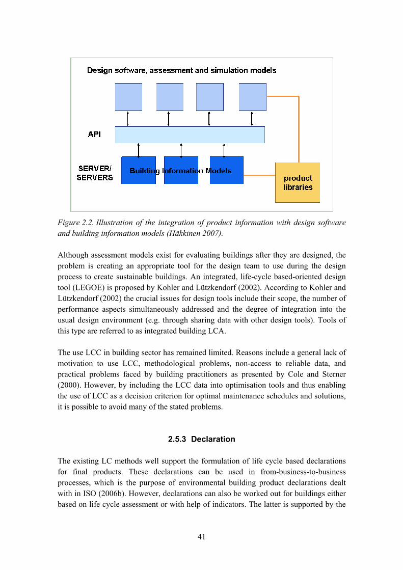
41
Figure 2.2. Illustration of the integration of product information with design software and building information models (Häkkinen 2007).
Although assessment models exist for evaluating buildings after they are designed, the problem is creating an appropriate tool for the design team to use during the design process to create sustainable buildings. An integrated, life-cycle based-oriented design tool (LEGOE) is proposed by Kohler and Lützkendorf (2002). According to Kohler and Lützkendorf (2002) the crucial issues for design tools include their scope, the number of performance aspects simultaneously addressed and the degree of integration into the usual design environment (e.g. through sharing data with other design tools). Tools of this type are referred to as integrated building LCA.
The use LCC in building sector has remained limited. Reasons include a general lack of motivation to use LCC, methodological problems, non-access to reliable data, and practical problems faced by building practitioners as presented by Cole and Sterner (2000). However, by including the LCC data into optimisation tools and thus enabling the use of LCC as a decision criterion for optimal maintenance schedules and solutions, it is possible to avoid many of the stated problems.
2.5.3 Declaration
The existing LC methods well support the formulation of life cycle based declarations for final products. These declarations can be used in from-business-to-business processes, which is the purpose of environmental building product declarations dealt with in ISO (2006b). However, declarations can also be worked out for buildings either based on life cycle assessment or with help of indicators. The latter is supported by the

42
existing sustainable building classifications methods such as for example the before mentioned PromisE system for new and existing buildings.
At present, the existing methods can be used in national level. The completion of the European and the international standards and methods will in future enable the LC information of buildings and building products valid internationally and/or in Europe (Häkkinen & Pulakka 2007).
2.5.4 Industrialised building processes
There are many differences between a traditional building process and an industrialised process; these differences also reflect to the tools needed for the information management. According to Lessing (2006), in an industrialised building process the majority of the planning and design is carried out as non-unique platforms instead of developing each building project individually with unique choices of technical solutions. The platform concepts are developed separately and in beforehand; as the specific building project proceeds the platform is used as a basis for further development of the project.
Industrialised building processes bring new kinds of needs for information management tools especially with regard to requirement setting. Requirement setting tools should at first support the concept development and finally the customisation of the concepts with the needs and requirements of individual users. This is further discussed by Åse Togerö in Chapter 3.
However, the use of service life estimation, LCA and LCC tools become easier and more meaningful in an industrialised building process compared to a traditional building process. A long-span development process of building concepts facilitates the use of different kinds of assessment tools and enables the process to seek for optimal alternatives. In addition, the development of databases that are needed in life cycle assessments, service life predictions and care and maintenance directions are meaningful to create and improve, because of the continuous nature of the process.
References
Bakens, W., Foliente, G. & Jasuja, M. 2005. Engaging stakeholders in performance-based building: lessons from the Performance-Based Building (PeBBu) Network. Building research and information: the international journal of research, development and demonstration, Vol. 33, No. 2, pp. 149�158.

43
BECOST. 2005. LCC and environmental assessment tool for buildings. Described in: http://virtual.vtt.fi/environ/ohjelmat_e.html.
CEN. 2005. BUSINESS PLAN CEN/TC 351 �Construction products: Assessment of release of dangerous substances�. In: http://www.umweltbundesamt.de/bauprodukte/dokumente/business-plan.pdf.
CIB. 1982. Working with the Performance Approach to Building. Report of Working Commission W60. Publication No. 64. Rotterdam: CIB.
Cole, R. 2004. Changing context for environmental knowledge. Building Research & Information, Vol. 32, pp. 91�109.
Cole, R. & Sterner, E. 2000. Reconciling theory and practice of life-cycle costing. Building Research and Information, Vol. 28, No. 5/6, pp. 368�375.
Cole, R., Howard, N. & Toshihau, I. 2005. Building environmental assessment tools: Current and future roles. In: http://www.sb05.com/homeE.html.
CPD. 1988. Construction Product Directive. Council Directive 89/106/EEC of 21 December 1988 in the approximation on the laws, regulations and administrative provisions of the Member States relating to construction products. Annex 1. In: http://ec.europa.eu/enterprise/construction/internal/cpd/cpd.htm.
EcoProP. 2006. Building performance requirement management EcoProP. In: http://virtual.vtt.fi/environ/vaatimus_e.html.
ENNUS. 2006. Service life assessment � ENNUS tools. In: http://virtual.vtt.fi/environ/ennus_e.html.
EPB. 2002. The European Directive 2002/91/EC on Energy Performance of Buildings.
EU. 2006. Europe, European Commission, Environment, Policies, sustainable development. In: http://ec.europa.eu/environment/eussd/.
Huovila, P. & Häkkinen, T. 2005. Eco-efficiency indicators for actors and products of building sector. In: SB05 Tokyo Proceedings. September 27�29, 2005. 4 p.
Huovila, P. & Porkka, J. 2005. Requirement management and EcoProP. In: http://virtual.vtt.fi/environ/vaatimus_e.html.
44
Häkkinen, T. 2007. Sustainable building related new demands for product information and product model based design. ITcon, Vol. 12, pp. 19�37.
Häkkinen, T. & Pulakka, S. 2007. Use of LC guides in open building manufacturing. In: Open Building Manufacturing: Core Concepts and Industrial Requirements. Ed. Katzi, S.
Häkkinen, T., Huovila, P., Bordeau, L. & Nibel, S. 2002. Network on Construction and City related Sustainability Indicators: Structuring of Indicators and status of work Summary Book and Proceedings (CD). Sustainable Building. International Conference. September 23�25, 2002. Oslo, Norway. 6 p.
Häkkinen, T. et al. 2004. Methodology for compiling environmental declarations for building products and for assessing environmental impacts of buildings. 73 p. In: http://virtual.vtt.fi/environ/ympsel_e.html.
IPP. 2003. Communication from the Commission to the Council and the European Parliament. Integrated Product Policy. Building on Environmental Life-Cycle Thinking. Commission of the European Communities. Brussels, 18.6.2003. COM(2003) 302 final. In: http://europa.eu.int/eur-lex/en/com/cnc/2003/com2003_0302en01.pdf.
ISO. 2000. ISO 15686-1:2000. Buildings and constructed assets � Service life planning � Part 1: General principles.
ISO. 2001. ISO 15686-2:2001. Buildings and constructed assets � Service life planning � Part 2: Service life prediction procedures.
ISO. 2006a. ISO/DIS 21930 Building construction � Sustainability in building construction � Environmental declaration of building products.
ISO. 2006b. ISO/FDIS 14025, Environmental labels and declarations � Type III environmental declarations � Principles and procedures.
ISO. 2006c. ISO/DIS 15686-8.2. Buildings and constructed assets � Service life planning � Part 8: Reference service life and service-life estimation.
ISO. 2006d. ISO 14040, Environmental management. Life cycle assessment. Principles and framework.
ISO. 2006e. ISO 14044, Environmental management. Life cycle assessment. Requirements and guidelines.

45
ISO. 2006f. ISO/DIS 15686-5, Buildings and constructed assets � Part 5 � Life cycle costing.
ISO. 2006g. ISO/TS 21929, Building Construction � Sustainability in Building Construction � Sustainability Indicators � Part 1 � Framework for the Development of Indicators for Buildings.
Kiviniemi, A. 2005. Requirements Management Interface to Building Product Models. CIFE CENTER FOR INTEGRATED FACILITY ENGINEERING. Technical Report 161. Dissertation. 328 p.
Kohler, N. & Lützkendorf, T. 2002. Integrated life-cycle analysis. Building Research & Information, Vol. 30, No. 5, pp. 338�348.
Lam, K. P., Wong, N. H., Mahdavi, A., Chan, K. K., Kang, Z. & Gupta, S. 2004. SEMPER II: an internet based multi-domain building performance simulation environment for early design support. Automation in construction, Vol. 13, pp. 651�663.
Lessing, J. 2006. Industrialised House-Building. Lund: Lund Institute of Technology.
Marteinsson, B. 2003. Durability and the factor method of ISO 15686-1. Building Research and Information, Vol. 31, pp. 416�426.
NORDTEST. 2001. Norwegian Council for Building Standardization. NS 3454. Life Cycle Costs for Building and Civil Engineering Work � Principles and Classification.
Shelbourn, M. A., Bouchlaghem, D. M., Anumba, C. J., Carillo, P. M., Khalfan, M. M. K. & Glass, J. 2006. Managing knowledge in the context of sustainable construction. ITcon, Vol. 11, pp. 57�71.
Shohet, I. M., Puterman, M. & Gilboa, E. 2002. Deterioration patterns of building cladding components for maintenance management. Construction Management and Economics, Vol. 20, pp. 305�314.
Sixth EAP. 2002. Sixth Environmental Action Programme of the European Community 2002�2012. In: http://ec.europa.eu/environment/newprg/index.htm.
TISSUE. 2004. Trends and indicators for monitoring the EU thematic strategy on sustainable development of urban environment. Final report. summary and recommendations. Ed. Tarja Häkkinen. Available in: http://cic.vtt.fi/projects/tissue/index2.html.

46
Trinius, W. 2005. Life performance and innovation on construction materials and components. In: Performance based buildings. Ed. Pekka Huovila. Published by VTT and RIL. Pp. 14�24.
Trinius, W. & Sjöström, C. 2005. Service life planning and performance requirements. Building Research & Information, Vol. 33, pp. 173�181.
Ugwu, O. O., Kumaraswamy, M. M., Kung, F. & Ng, S. T. 2005. Object-oriented framework for durability assessment and life cycle costing of highway bridges. Automation in construction, Vol. 14, pp. 611�632.
Vesikari, E. 2007. Life cycle management tool for buildings. Manuscript for Durability of Building Materials and Components 2008 Conference. 11 p.
Öberg, M. 2005. Integrated life cycle design. Application to Swedish concrete multi-dwelling buildings. Report TVBM-1022. Lund.
47
Chapter 3
Author Carl Jonsson
Contents
3. The industrialised building process ...........................................................................48 3.1 Main ingredients in the industrialised building process ...................................48 3.2 Why choose an industrialised building process?..............................................49 3.3 Components and interfaces...............................................................................50 3.4 Concepts and projects.......................................................................................51 3.5 The process phases and product models...........................................................52 3.6 The planning phase...........................................................................................53 3.7 The execution phase .........................................................................................55 3.8 Different ways to apply a building concept......................................................57 3.9 What is most important to hold on to in a building concept?...........................58 3.10 Traditional and industrialised design processes in a concept...........................58 3.11 Production cost .................................................................................................60 3.12 Concept maintenance and concept life cycle....................................................61 3.13 ILCD tools in the industrialised process ..........................................................63 3.14 Summary and conclusions................................................................................63 References..................................................................................................................64
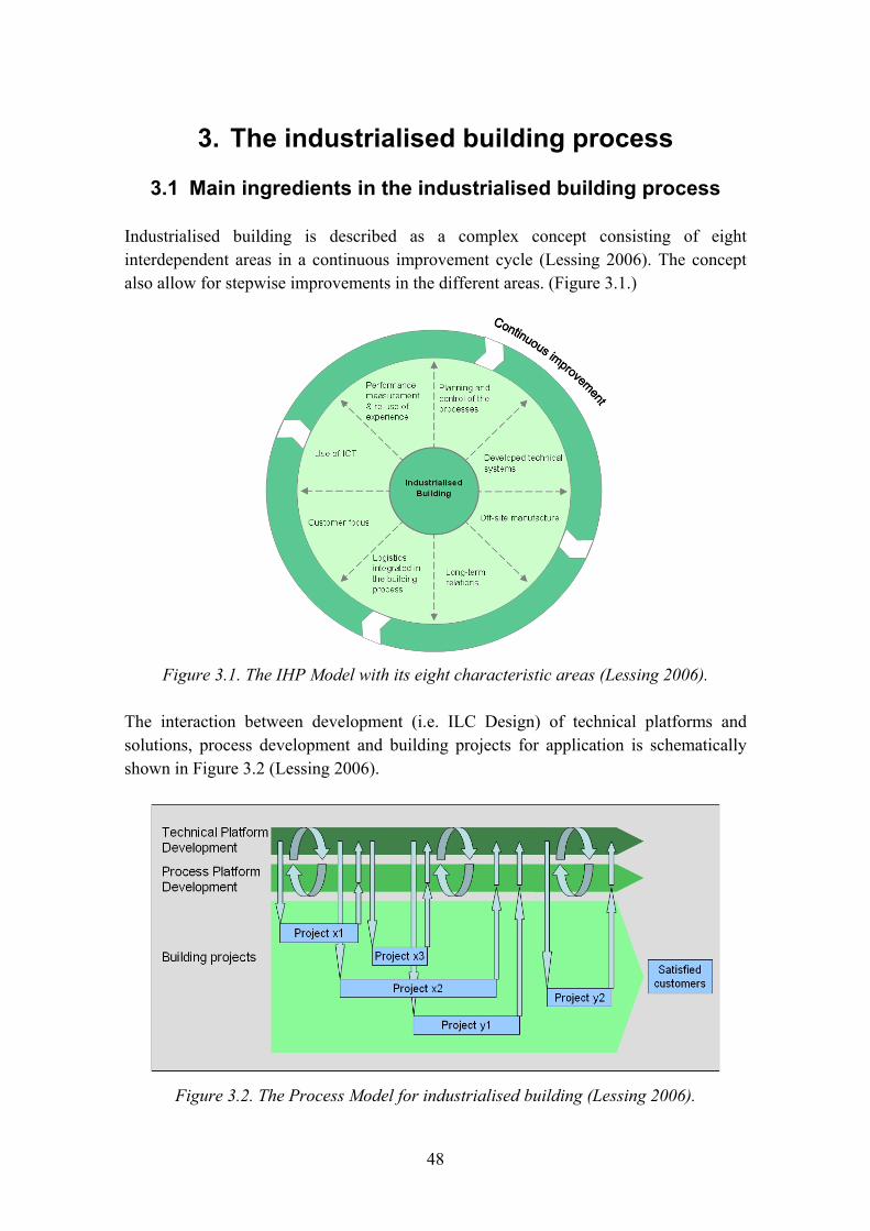
48
3. The industrialised building process
3.1 Main ingredients in the industrialised building process
Industrialised building is described as a complex concept consisting of eight interdependent areas in a continuous improvement cycle (Lessing 2006). The concept also allow for stepwise improvements in the different areas. (Figure 3.1.)
Figure 3.1. The IHP Model with its eight characteristic areas (Lessing 2006).
The interaction between development (i.e. ILC Design) of technical platforms and solutions, process development and building projects for application is schematically shown in Figure 3.2 (Lessing 2006).
Figure 3.2. The Process Model for industrialised building (Lessing 2006).

49
3.2 Why choose an industrialised building process?
Compared to traditional construction, the end product will have:
− the same or better standard − higher quality in technical solutions − detailed planning solutions, optimised on requested functions − optimised physical performance (indoor environment, energy, acoustic).
Since, in a concept, we have the possibility to grasp the whole building process and penetrate it in detail, each sub-process can be optimised in a controlled flow. Neither technical development, purchasing nor production planning is performed in the execution phase. The processes are decided before they are launched for production. If the concept is wide, this doesn�t limit the architectural possibilities. Instead, the architect can work on the functions that really create value for the client and the society. The architects and engineers can focus on ILC design outside the building process. This is a way of moving the prototype from the market to the laboratory.
Since the components and processes are controlled, the deviation and spread of performance decrease. This means the risk of non-performance is very low (Figure 3.3).
Figure 3.3. Comparison on performance between traditional and industrial construction.
However, this requires that the development teams do their work, since a bad technical solution for a component will result in a big damage due to large volumes.

50
3.3 Components and interfaces
One essential part of industrialisation is to identify the best technical solutions. These solutions must then be productified, standardised and assorted. Examples on technical solutions are bathrooms, roofs, plant rooms, kitchen, electrical installations, structural elements, sanitary equipment, ventilation risers et cetera. An important part of industrialisation is to minimise the number of interfaces on the site. The number of interfaces in the assembly on site decreases exponentially (Figure 3.4).
Traditional building process 24 interfaces
Industrialised building process 4 interfaces
Figure 3.4. Number of interfaces in traditional and industrial construction.
It is not only the number of physical interfaces that influence the degree of industrialisation. If the components offered in a concept are combined (packacked) into big modules (e.g. apartments, common areas, roofs et cetera), the number of interfaces in the planning phase are minimised and the planning is easier to control. (Figure 3.5.)
Prior to launching, the assembled components must undergo a development program (program for ILC Design), where they are tested and verified, calibrated and adjusted, packaged and implemented in accordance with a predefined process.

51
Figure 3.5. Schematic of the development of industrialised modules in Skanska.
3.4 Concepts and projects
Concepts are developed in specialised units. When it is ready for launch (after a few pilot projects), the concept is marketed, maintained and further developed by a separate concept owner organisation. The concept owner supplies the producing units with concept material, directions and support. He also gathers follow-up information from completed projects, analyses and initiates any measures for corrections. Handling of versions that are allowed for selling, and using has the same setup as for e.g. the car or computer software industry. (Figure 3.6.)

52
Industrialized The industrialized building
Figure 3.6. Illustration of industrialisation.
3.5 The process phases and product models
The industrialised building process can be split in the main phases Project development, Design & preparations and Assembly & handing over. The main processes for the concept ModernaHus are shown in Figure 3.7 (SKANSKA, Jonsson 2007).
Figure 3.7. Process and information models in a project.
In the building process, all designs and preparations are finalised prior to assembly start on site. Part of the components are manufactured and assembled in factories in accordance with concept purchasing agreements. The components are delivered and assembled in accordance with tested and verified assembly methods.

53
3.6 The planning phase
In the planning phase, the product model undergoes development from a low to a higher and higher level of resolution. In contrast to traditional project development, this is performed by a limited set of predefined choices. (Figure 3.8.)
Figure 3.8. Simplified planning phase for the concept ModernaHus.
Product model 0 to IV (PM0�IV)
The choices made within the frame of the concept are fully supported by documentation and directions. The less customisation, the safer and less costly product and the faster process. Project specific customisations are developed in a traditional way, but have to fit in the process and system criteria.
PM 0 � Program
A proposal is prepared by the concept architect based on the concept material (building types or predefined apartments, staircases, balconies, roofs et cetera). Project customisations can be made with the common CAD functions (Figure 3.9). Cost indication and time schedule is calculated on the basis of concept key figures.
The proposal is either made in a project development or as a bid in a tender.
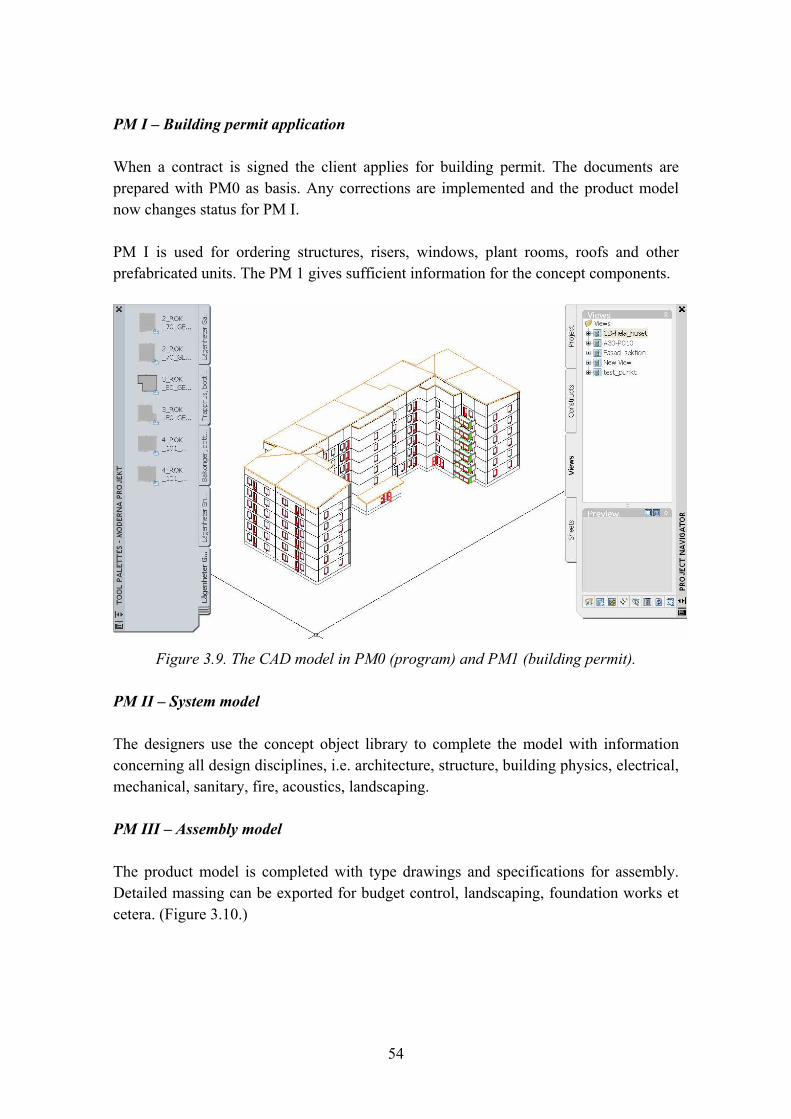
54
PM I � Building permit application
When a contract is signed the client applies for building permit. The documents are prepared with PM0 as basis. Any corrections are implemented and the product model now changes status for PM I.
PM I is used for ordering structures, risers, windows, plant rooms, roofs and other prefabricated units. The PM 1 gives sufficient information for the concept components.
Figure 3.9. The CAD model in PM0 (program) and PM1 (building permit).
PM II � System model
The designers use the concept object library to complete the model with information concerning all design disciplines, i.e. architecture, structure, building physics, electrical, mechanical, sanitary, fire, acoustics, landscaping.
PM III � Assembly model
The product model is completed with type drawings and specifications for assembly. Detailed massing can be exported for budget control, landscaping, foundation works et cetera. (Figure 3.10.)

55
Templates for estimations are based on followed-up assembly methods and checked labor consumption. The program is coordinated by integration between the estimation and project planning tool. The estimate also gives input to the project purchasing plan.
Figure 3.10. Massing and assembly drawings come from the same model.
3.7 The execution phase
The assembly is split into three main phases; Ground phase (excavation, site establishment, foundation works), Wet phase (structures, wet prefab units) and Dry phase (completions, interior dry works, landscaping). Below, the activities in each main phase are briefly described for the assembly of an 8 story point block residential building containing 32 units (Figure 3.11).
Massing Drawings

56
I. GROUND PHASE
Excavation, site establishment
8 weeks
Establishment Excavation, terrace works Connections for infrastructure, electricity, sewage, district heating Assembly of prefab foundations and lift pits Insulation, reinforcement, in-situ concreting
II. WET PHASE
Structures, prefab units
8 weeks
Crane assembly Assembly of prefab structure Assembly of bathrooms Delivery of apartment goods to each apartment Assembly of prefab electrical service and group centrals District heating and main power connections Assembly of prefab ventilation and sanitary risers Water and sewage connections to kitchen sink Assembly of plant and fan rooms on top floor Concrete screed Connection boxes for risers Installation of heating system Temporary lift installation Assembly of prefab roof structures, canopies, dewatering, roof safety
III. DRY PHASE
Completions
22 weeks
Painting and wallpaper works Flooring works Installation of lightweight partitions Kitchen installation Apartment el, tele, data Installation of metering systems White goods, doors Iron mongery Lift installation Landscaping, complementary building Final cleaning Final inspection Site de-establishment
Figure 3.11. Illustration of the execution phase.

57
3.8 Different ways to apply a building concept
End products such as multi-family housings contain quite a lot of functions and components. It is often wise to allow for a certain degree of flexibility and customisations. It would be very costly and time consuming to aim for a concept with such an assortment that it could supply even part of the market with 100% concept solutions. (Figure 3.12.)
For ModernaHus, a potential project can be created if it belongs to any of three categories:
Figure 3.12. Different ways to create a housing project.
A. Ready products
The products can be point or slab blocks. These should be the most cost effective configurations with a retained high standard.
B. Apply the concept to create the product
Configuration of the product with the ready concept solutions by combining the modules to fit the project. The ready modules and system criteria for the concept shall be utilised fully.
C. Apply the concept to create the product with customisations
Same as above but with necessary customisations. The strategic components may not be changed. Other components and planning solutions may be changed to a certain degree (e.g. 25%).

58
3.9 What is most important to hold on to in a building concept?
In order to succeed with a concept, to keep the organisation on the same track and to establish a brand, it is necessary to establish and follow a set of rules characteristic to the concept. Typical rules in the design and preparation phase are to stick to:
− planning stages PM 0 � PM IV − geometric standard and system criteria − strategic components, e.g.
o structural elements incl. assembly methods o wetrooms, kitchens and risers and how these can be combined o prefabricated electrical installations o prefabricated fan rooms and plant rooms and how these can be placed o heating system incl. radiators, risers and air intakes and how these can be placed o windows, floors, doors
− purchasing plan (max XX% deviations from the concept template) − everything planned before assembly start − no technical development in the building process.
Likewise, there are some rules in the assembly phase. For example, they could be to stick to:
− high degree of prefabrication − focus on main phases (ground phase, wet phase, dry phase) − minimum of external works (no scaffolding) − supplied units and material.
Again, why is this so important? Otherwise the building process can not be applied, e.g. the supply chain (windows, wetrooms, screed�), assembly teams will not be correctly trained and efficient, design teams will not have the correct resources, training, efficiency and so on. Also, very important, the concept stands for a set of agreed performances. If the rules are not followed, these performances will likely not be met (compare Figure 3.3). This may concern time schedule, costs, technical performance, operation and maintenance conditions et cetera.
3.10 Traditional and industrialised design processes in a concept
Since a concept has a more strict application and limitations, there are large opportunities to increase efficiency in the design process. Complicated tasks in a traditional design are to control the input to the design team and to coordinate the design material between disciplines. Figures 3.13 and 3.14 illustrate schematic examples on
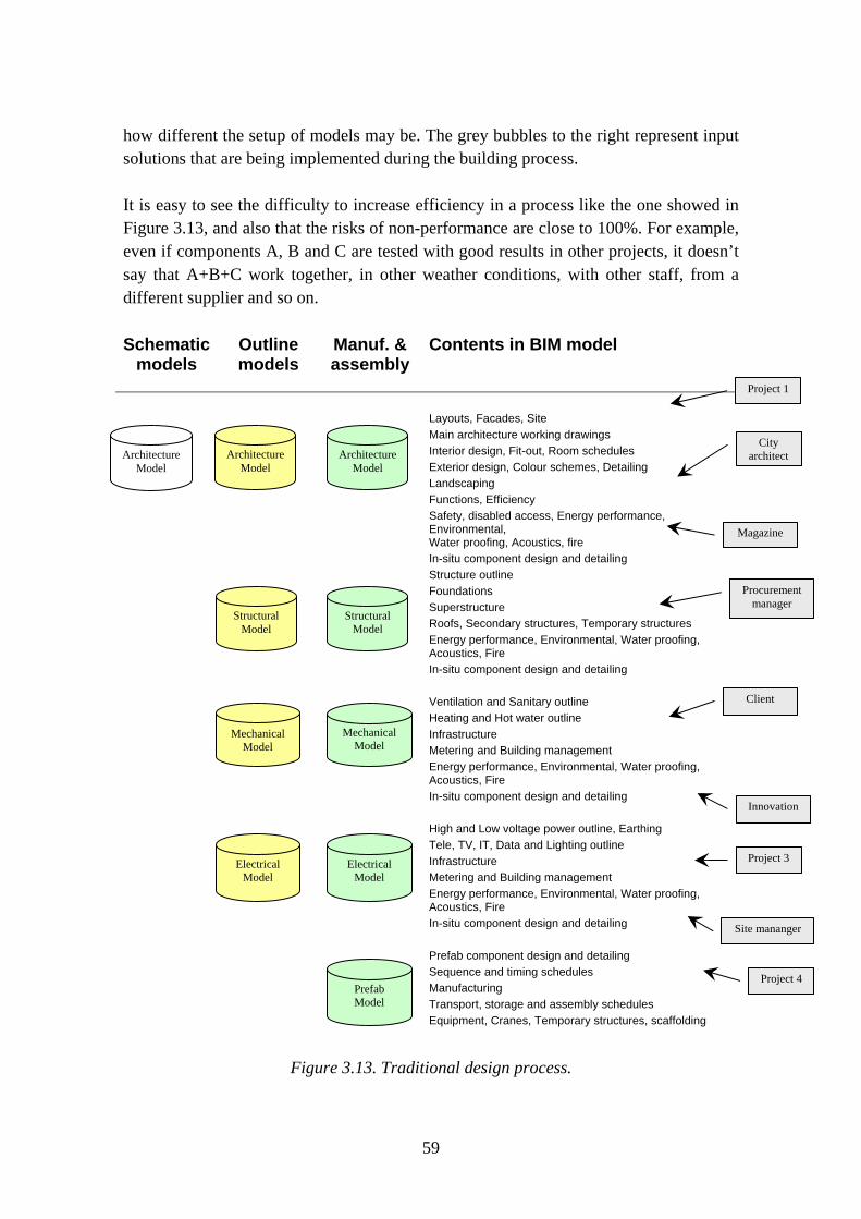
59
how different the setup of models may be. The grey bubbles to the right represent input solutions that are being implemented during the building process.
It is easy to see the difficulty to increase efficiency in a process like the one showed in Figure 3.13, and also that the risks of non-performance are close to 100%. For example, even if components A, B and C are tested with good results in other projects, it doesn’t say that A+B+C work together, in other weather conditions, with other staff, from a different supplier and so on.
Schematic models
Outline models
Manuf. & assembly
Contents in BIM model
Layouts, Facades, Site
Main architecture working drawings
Interior design, Fit-out, Room schedules
Exterior design, Colour schemes, Detailing
Landscaping
Functions, Efficiency
Safety, disabled access, Energy performance, Environmental, Water proofing, Acoustics, fire
In-situ component design and detailing
Structure outline
Foundations
Superstructure
Roofs, Secondary structures, Temporary structures
Energy performance, Environmental, Water proofing, Acoustics, Fire
In-situ component design and detailing
Ventilation and Sanitary outline
Heating and Hot water outline
Infrastructure
Metering and Building management
Energy performance, Environmental, Water proofing, Acoustics, Fire
In-situ component design and detailing
High and Low voltage power outline, Earthing
Tele, TV, IT, Data and Lighting outline
Infrastructure
Metering and Building management
Energy performance, Environmental, Water proofing, Acoustics, Fire
In-situ component design and detailing
Prefab component design and detailing
Sequence and timing schedules
Manufacturing
Transport, storage and assembly schedules
Equipment, Cranes, Temporary structures, scaffolding
Figure 3.13. Traditional design process.
Procurement manager
Project 4
Project 1
City architect
Site mananger
Magazine
Client
Project 3
Structural Model
Structural Model
Mechanical Model
Electrical Model
Electrical Model
Prefab Model
Architecture Model
ArchitectureModel
Architecture Model
Innovation
Mechanical
Model

60
Schematic models
Outline models
Manuf. & assembly
Contents in BIM model
Menu choices and assembly Configuration Customization
Menu choices and assembly Configuration Customization
Menu choices and assembly Configuration Customization
Figure 3.14. Industrialized design process.
In the industrialized design process, there is no development. This means the product models can be merged in fewer disciplines. The main work is to configure and assemble ready made modules. Except for the client, input solutions are handled outside the building process. Changes and development (i.e. ILC Design) are instead made in a concept group, directed by the concept owner.
3.11 Production cost
In a concept, it is essential to have control on the main factors that influence the cost. As an example, a project configured with the ModernaHus concept, will be influenced mainly by the following factors;
− number of m2 letable area − number of m2 gross area − number of m2 footprint area − number of stories − number of apartments − number of staircases − number of plant rooms − degree of conformity.
Client
Concept
Prefab Model
Services Model
Building Model
Building Model
Building Model
61
If we take into account life cycle costs of energy use, operation and maintenance, we have to add:
− façade area − window area.
Note, these are variables within the concept. If we go outside the concept, e.g. changing heating system, other variables will apply.
As an example, ModernaHus is optimised from a production cost perspective for an 8 story point block with 32 units. If the number of stories is less, the cost/m2 increases. Another example; the plant rooms are maximised for 36 units. The cost for plant rooms if it is 40 units will be higher than for 70 units. So, the skill in using these factors in the planning will essentially influence the project economy. This is not so obvious in traditional construction.
A cost driving factor is when deviations to the concept must be made. It could concern:
− other functions than the available that must be implemented
− other layout planning than the available. Also smaller deviations may have big influence
− other technical solutions than the available.
3.12 Concept maintenance and concept life cycle
A Concept Group with a Concept Owner is responsible for developing, marketing and maintaining a concept. They decide the scope and contents of the concept (portfolio), they control the life cycle, release handling, implementation, communication and training. They also support the projects in sales and delivery. Figure 3.15 shows the main processes for maintaining a concept from start and over time. The input that forms the initial concept criteria comes mainly from a company strategy and experience from reference projects. During the initial development phase, the input comes from market investigations, innovations, full scale tests and pilot projects. Generally, a concept undergoes great improvements after release. The input for improvements once the concept is launched comes from real application, problems in the processes, new procurement opportunities, new market situations, new innovations. It is a tough task to decide when to launch a concept. A too early launch will result in excessive operation costs and bad publicity for the brand. A late launch obviously delays income.

62
Figure 3.15. Concept maintenance.
A concept life cycle undergo development, introduction, growth, maturity and retardation. A successful concept will put input and proposals for further improvements to the Concept Group. Smaller changes will be implemented as �service packs� in the existing release. Bigger changes will be summed up for new development, release and the start of a new life cycle, see Figure 3.16.
Figure 3.16. Concept life cycle.
63
3.13 ILCD tools in the industrialised process
The development of new tools in the building sector is amazing in general. The possible level of detail in the product model is close to endless. The problem in the traditional building process is that it can not be utilized. The time to survey, collect data, negotiate, make the correct decisions, implement it in the model, mass, plan, prepare integrated analysis, finally choose and decide is too long. In the traditional building process, the components must be purchased long before the design output is really useful! It is hardly possible to complete a proper ILCD in a traditional building process before the contracts are signed and the purchasing has started.
In the industrialised process however, it�s different. Since the technical solutions will be developed separately for launch to a concept, the process for e.g. ILCD is much more suitable. But the ILCD will be made as a development, not inside the building process. In the building process, we should only choose from a limited assortment of ready solutions, where the performance and possible applications already have been analyzed.
The tools used today should undergo a change from advanced engineering tools to something more suitable for development and application of concepts. For the development, there is a possibility to use sophisticated expert tools. For the application in projects, we may only use the tabulated results, and simple combination or superposition.
For example, today in a project where a structural solution should be used in a single project of say 50 units, we may only put the effort in designing the structure with commercially commonly available engineering software, simplified models and rough assumptions. In a development of a concept where the solution will be used for say 50.000 units, it may be worth the effort to study e.g. fracture mechanical behavior for some details, or non-linear and time dependant factors for soil-structure interaction et cetera. The same applies for e.g. energy or acoustic simulations, mold and fire proofing.
3.14 Summary and conclusions
To introduce an industrialised building process will turn any organisation, work procedures and traditional methods over. It will have impact not only on each individual in the organisation, but also on the supply chain and consultants.
The industrialised components and technologies are important ingredients, but to reach the beneficial effects, the processes involved in all stages from planning, purchasing, manufacturing and assembly must be penetrated and adjusted, i.e. towards lean planning, lean purchasing, lean manufacturing, lean assembly.
64
The application of concepts in the building process calls for a change of staff expertise, tools and engineering software. The future should supply:
− Increased use of experts and expert tools for the development of new technical solutions.
− Increased use of scale testing tools, e.g. mock-ups and Monte Carlo simulations.
− Engineering draftsmen with CAD and IT skills and simple �table tools� for the design in the building process. Decreased use of advanced engineering calculations in the building process.
References
Jonsson, C. 2007. ModernaProjekt. Development project paper.
Lessing, J. 2006. Industrialised House-Building. Lund: Lund Institute of Technology.
SKANSKA. ModernaHus. Concept for multi-family housing. SKANSKA. Project Industrialisation. Development project.
65
Chapter 4
Authors Tarja Häkkinen and Sirje Vares
Contents
4. Whole-life optimisation of buildings and BIMs ........................................................66 4.1 Introduction ......................................................................................................66 4.2 Product information..........................................................................................67 4.3 Building Information Model � BIM.................................................................69 4.4 Integration of product information with BIMs.................................................71 4.5 Product libraries ...............................................................................................74 4.6 Techniques for publishing and finding product information in web................76 4.7 Case LifePlan ...................................................................................................77 4.8 Case ENNUS CONCRETE..............................................................................81 4.9 Conclusions ......................................................................................................83 References..................................................................................................................84
66
4. Whole-life optimisation of buildings and BIMs
4.1 Introduction
Sustainable building will increase the use needs of product information and different kinds of assessment and simulation models both in building processes as well as during the maintenance of buildings. Service life design and design for sustainable and healthy built environment need new type of information including for example service life information, life cycle assessment (LCA) data and information about harmful chemicals and emissions. Design for service life and sustainability may also require detailed information about technical performance of products.
ISO TS 21929 (ISO 2006) defines that sustainable construction brings about the required performance with the least unfavourable environmental impact, while encouraging economic, social and cultural improvement at a local, regional and global level. Life cycle management and improved sustainability of buildings will require the development of building product information and its processes of use. It will be necessary to develop the contents and supply of information as well as the models of exchange and use of this information in order to ensure the management of the required building performance and environmental impacts during the life cycle of buildings. The abundance of this information provided by suppliers and manufacturers and the different needs in different stages of the building process requires the development and use of new information technological solutions.
With help of product modelling it is possible to efficiently handle increased amount of product information. IFC-standards have been developed in international co-operation in order to harmonise building information representation and its transfer. The target is that all information in building sector could be easily exchanged from one actor to another, within design, and between different stages during the building lifecycle. Even though IFC is meant to cover all the building life cycle phases, it is so far concentrated mostly on the generic information used in the design phase (Siltanen et al. 2007).
On the other hand, many players in Architectural-Engineering-Construction (AEC) community have developed computational systems and estimation programs using data structures that are not compatible with the IFC standard. These applications can use product-specific information, i.e. information produced by the suppliers or vendors of the actual products used in the construction. However, they are often based on manual data input where the user reads data from suppliers brochures and types the data manually via the application�s user interface.
67
4.2 Product information
Life-cycle management and consideration of health risk aspects of buildings require that product-specific information is available on life cycle costs, environmental impacts, and use of chemicals, care and maintenance methods and periods of renewals. On the other hand product-model based building facilitates the inclusion of product-specific information in building design and in the formulation of care and maintenance �manuals�. Established methods and practices to include products specific information into building specific product models do not exist, but these have to be developed and agreed upon. Table 4.1 characterises the needs of product information in different task of design, building and maintenance (Häkkinen 2007).
Finne (Finne 2003) describes three levels of product specific information:
− Level 1: Basic contact information: Name, Address, telephone, web-site of the manufacturer or supplier.
− Level 2: Detailed product information as presented in product data sheets.
− Level 3: Fully functional on-line auctions and purchasing portals.
Level 1 and 2 information is represented in various formats:
− as unstructured representation: text (PDF) documents, contracts, email messages etc.
− as semistructured representation: HTML documents, Excel spreadsheets etc.
− as structured representation: electronic product catalogues, databases.
In an ideal case, product information is linked to the CAD model in the design phase (see e.g. Gudnason et al. 2005), and CAD applications do usually provide some sort of product information in their material libraries. This information should then be stored into the building information model and it should be able to be used by all the software needing the information. However, the information in the CAD material libraries is normally too general and limited to be useful in the software using product-specific information. Also, the product information publishing process is often separated from the design process, and it uses totally different tools.

68
Table 4.1. Needs of product information in different tasks of building and maintenance process.
TASK NEEDED INFORMATION 1 service life design preconditions (concerning assembling, details and structures,
use and environment) that are necessary for the estimated service life. Alternatively: the corresponding information in a format of a computational programme with help of which the effect of these parameters can be calculated
2 design for required building performance
technical performance
3 life cycle assessment of building parts and buildings
environmental profile and estimated service life and renewal periods of components and coatings
4 estimation of life cycle costs
cost information including costs from workmanship, estimated service life and renewal periods of possibly included components and coatings
5 design for healthy indoor conditions
indoor air emissions, preferably in terms of classification
6 design for low environmental risks
information about product composition, use of chemicals and emissions to land and water during use
7 design of care and maintenance
estimated service life, renewal periods of components and coatings, requirements with regard to inspections, care and maintenance
8 optimisation of the processes of maintenance
age behaviour, alternative options for care and maintenance, life cycle costs of maintenance measures a model which enables to compare and optimise alternative options of maintenance
9 care and maintenance instructions for care and maintenance system specifically grouped and scheduled data of all care and maintenance measures
10 repair and refurbishment
information on realised building solutions information about requirements concerning the handling and treatment of products to be demolished, surface treated etc.
11 reuse and recycling products or disposal of products after service life
guidelines for reuse, recycling and disposal (compare 6)
There is an active process going on aiming at the formulation of international and European standards for the assessment and declaration methods of environmental aspects and service life performance of buildings and building products (see further information in Chapter 2). If these standardisation efforts prove successful, a common understanding about the contents and structure of building product information will significantly help the possibilities of product libraries to deliver product information for the needs of building design and selection of products in building process (Häkkinen
69
2007). Currently these standards describe only unstructured documents which are meant to be read by humans, not by computer programs. There is a great number of software that needs specific product information, e.g.: requirements management software, architectural and structural engineering software, simulation and estimation programs, service life estimation and facility management tools and programs. For these applications, it is necessary to specify data representations that have exact representation syntax, based on the commonly agreed terminology (Siltanen et al. 2007).
4.3 Building Information Model � BIM
Building Information Model (BIM) is a standard digital information repository of building design, which may also contain information about the building�s construction, management, operations and maintenance. Generally, a BIM consists of two kinds of information: building elements and their attributes and the relationships between these building elements. In comparison to earlier CAD systems, BIM-based CAD systems are building object-oriented systems, in which the basic components are building elements like walls, doors, windows rather than geometric elements in earlier CAD systems (Fu et al. 2006).
BIM is believed to be essential in AEC and the real-estate industries to share and exchange information among project stakeholders, such as architects, engineers, contractors, owners and facility managers. In addition to the support for share-out of information, BIM should also be able to support the information management. Using BIM rather than CAD geometric models to represent and deliver the information and data throughout the lifecycle of a building project is increasingly becoming a consensus between the researchers and practitioners in the AEC industry (Fu et al. 2006).
The processes of building information modelling are to classify and standardise design and planning information, which usually fragmentally exists in a variety of phases and aspects of a building project. Moreover, another reason to apply BIM is to standardise and format the building information to suit the requirement and format of interfaces, databases, file and data exchange in computer applications.
International Alliance for Interoperability has developed a data model for Building Information Model. IFC-standards (Industry Foundation Classes) have been developed in international co-operation in order to harmonise building information and aid its transfer. The first version of the IFC-version, 1.0 was released in 1997. The first versions comprised only geometry transfer; but later versions have added a lot of capabilities to represent more entities and more relationships related to the building�s lifecycle. IFC standard has suitable methodologies for specifying the data

70
representation. The IFC classes are not defined for every conceivable product type within a constructed entity, but represent generic categories of element (e.g., wall, beam, space). However, IFC incorporates a mechanism called Property Sets which allow information publishers to allocate new properties to an object they wish to describe. Representation syntax based on commonly agreed terminology can therefore be implemented in IFC (Siltanen et al. 2007).
Currently, IFC (Industry Foundation Classes) is becoming the dominant BIM information exchange standard strongly promoted by property owners. IFC specifications can be used to describe integrated information of a product including geometry, topology, tolerances, relationships, attributes, assemblies, configuration and others of a product�s whole lifecycle. IFC is developed by the International Alliance for Interoperability (IAI). It is particularly focused on the product and process modelling of the AEC/FM industry. The IFC model defines an integrated schema to depict the main physical and logical building objects, their characteristics and their inter-relationships in the form of a class hierarchy. The IFC hierarchy covers the core project information such as building elements, the geometric and material properties of building product, project costs, schedules and organizations. Moreover, IFCs enable interoperability among AEC/FM software applications and this means the end-users in the AEC/FM area can effectively share the model data through IFC files.
Today, the most important CAD systems support the export of drawings into IFC model files (Fu et al. 2006). The latest IFC model release, IFC2x3, includes model extensions that specifically support interoperability after the CAD design phase. It includes substantial model enhancements for three major industry domains � HVAC, electrical, and structural � as well as enhancements to modelling of building architecture, and facilities management. The IFC data model of buildings has reached a maturity that makes in increasingly beneficial to developers of downstream applications that support processes during a building�s life cycle to implement the model in their software (Bazjanac 2004).
The vision of BIM is that all the information produced during the building design process is stored in one model that is independent of any individual use cases. Each individual software used during the building lifecycle can access and update the information, creating an incremental data flow of all the information related to the building design and maintenance process. The vision is compelling since it would eventually solve most of the interoperability problems faced in the construction industry today (Siltanen et al. 2007).
There are several CAD tools that support � to some extent at least � IFC specification, but a large number of software used in everyday building projects cannot export or
71
import IFC data. Early experiences from HUT 600 project (Fisher & Kam 2002) show that IFC information exchange was not mature at that time. Some progress has happened since then, but the idea of lossless data flow between all the software used in the projects has not yet come true (Kiviniemi 2005a).
The Finnish ProIT project (ProIT 2005) described the framework for product model based design, construction and maintenance process. The project studied building projects as examples, which tested potentials of product models with regard to different information management cases. The best experiences were received with bill of quantities and cost accounting. Bill of quantities is an obvious example of potential advantages. Because the current and widely used design software products are already based on product models � although they have their own internal model � and because the representation of geometry of building objects is already included, the inclusion of data that is related to geometrical data is one of the easiest tasks. Correspondingly it should be moderately easy to include LCA based calculations into the product model with help of object technology because environmental impacts are proportional to the quantities of products as well. The so-called environmental profiles of products are lists of emissions and resources consumptions normally given per mass quantities of products.
4.4 Integration of product information with BIMs
According to Kiviniemi (2005b) the instantiated model of a project, i.e. project�s data set should be divided into four separate models: Requirement model, design model, production model and maintenance model. The information content in the different design and contractor domains is so different that there is a need for several design and production models. According to Niemioja (2005) the architect�s product model may include product specific data, but basically the model is a building part model (as designed). The final up-dating of the product model is done on the basis of construction process (as built). In this model the supplier-specific information are linked with all building parts and equipment.
Figure 4.1 illustrates five building information models as discussed in two recent EC funded research projects: Performance Based Building (PeBBu 2002�2005) and Integration of performance based building standards into business processes using IFC standards to enhance innovation and sustainable development (Stand-Inn 2006�2008).
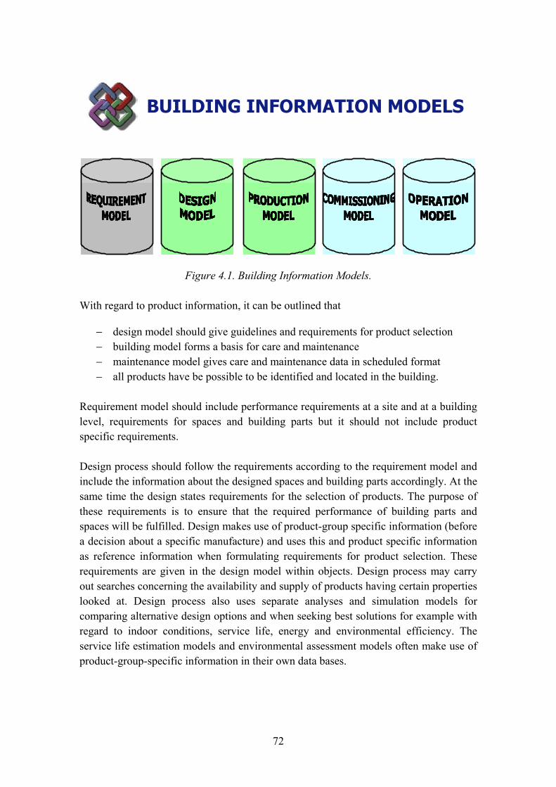
72
BUILDING INFORMATION MODELS
Figure 4.1. Building Information Models.
With regard to product information, it can be outlined that
− design model should give guidelines and requirements for product selection − building model forms a basis for care and maintenance − maintenance model gives care and maintenance data in scheduled format − all products have be possible to be identified and located in the building.
Requirement model should include performance requirements at a site and at a building level, requirements for spaces and building parts but it should not include product specific requirements.
Design process should follow the requirements according to the requirement model and include the information about the designed spaces and building parts accordingly. At the same time the design states requirements for the selection of products. The purpose of these requirements is to ensure that the required performance of building parts and spaces will be fulfilled. Design makes use of product-group specific information (before a decision about a specific manufacture) and uses this and product specific information as reference information when formulating requirements for product selection. These requirements are given in the design model within objects. Design process may carry out searches concerning the availability and supply of products having certain properties looked at. Design process also uses separate analyses and simulation models for comparing alternative design options and when seeking best solutions for example with regard to indoor conditions, service life, energy and environmental efficiency. The service life estimation models and environmental assessment models often make use of product-group-specific information in their own data bases.
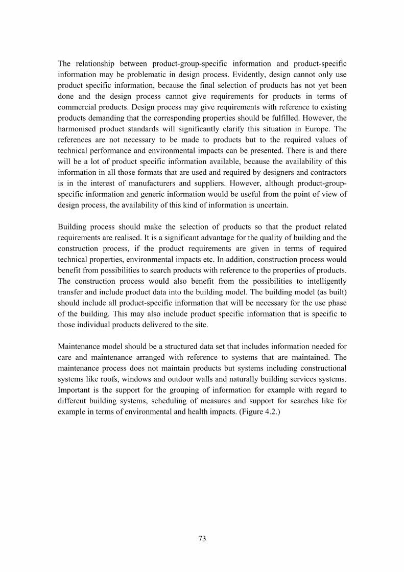
73
The relationship between product-group-specific information and product-specific information may be problematic in design process. Evidently, design cannot only use product specific information, because the final selection of products has not yet been done and the design process cannot give requirements for products in terms of commercial products. Design process may give requirements with reference to existing products demanding that the corresponding properties should be fulfilled. However, the harmonised product standards will significantly clarify this situation in Europe. The references are not necessary to be made to products but to the required values of technical performance and environmental impacts can be presented. There is and there will be a lot of product specific information available, because the availability of this information in all those formats that are used and required by designers and contractors is in the interest of manufacturers and suppliers. However, although product-group-specific information and generic information would be useful from the point of view of design process, the availability of this kind of information is uncertain.
Building process should make the selection of products so that the product related requirements are realised. It is a significant advantage for the quality of building and the construction process, if the product requirements are given in terms of required technical properties, environmental impacts etc. In addition, construction process would benefit from possibilities to search products with reference to the properties of products. The construction process would also benefit from the possibilities to intelligently transfer and include product data into the building model. The building model (as built) should include all product-specific information that will be necessary for the use phase of the building. This may also include product specific information that is specific to those individual products delivered to the site.
Maintenance model should be a structured data set that includes information needed for care and maintenance arranged with reference to systems that are maintained. The maintenance process does not maintain products but systems including constructional systems like roofs, windows and outdoor walls and naturally building services systems. Important is the support for the grouping of information for example with regard to different building systems, scheduling of measures and support for searches like for example in terms of environmental and health impacts. (Figure 4.2.)
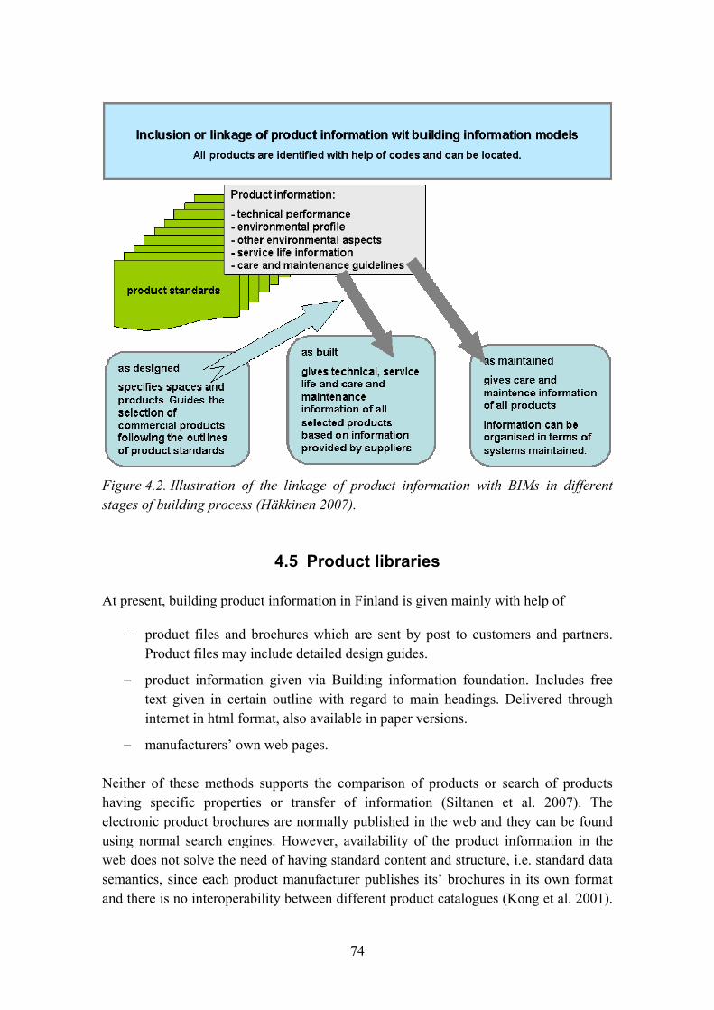
74
Figure 4.2. Illustration of the linkage of product information with BIMs in different stages of building process (Häkkinen 2007).
4.5 Product libraries
At present, building product information in Finland is given mainly with help of
− product files and brochures which are sent by post to customers and partners. Product files may include detailed design guides.
− product information given via Building information foundation. Includes free text given in certain outline with regard to main headings. Delivered through internet in html format, also available in paper versions.
− manufacturers� own web pages.
Neither of these methods supports the comparison of products or search of products having specific properties or transfer of information (Siltanen et al. 2007). The electronic product brochures are normally published in the web and they can be found using normal search engines. However, availability of the product information in the web does not solve the need of having standard content and structure, i.e. standard data semantics, since each product manufacturer publishes its� brochures in its own format and there is no interoperability between different product catalogues (Kong et al. 2001).

75
The catalogues are published in HTML, PDF or other unstructured format, ignoring the need of computer readable formats to automate the data exchange.
Web-based construction products catalogues, which enable interoperability through Web-services technologies offer efficient models for information sharing (Kong et al. 2005). As described by stated by Shailesh and Godfried (2003) there are two approaches commonly used for finding products in e-Catalogues: 1) descriptive searches which are based on matching text strings and 2) attribute-based searches which are based on matching products. A descriptive search typically produces large sets of product lists. Attribute searches assume that products can be selected on the basis of their attributes. This requires that 1) the user has knowledge of the attributes on which to search, 2) the user is aware of the acceptable range of values for each attribute, 3) the user understands the significance of each attribute in the design. Attribute searches are suitable in the construction phase of project when detailed product specifications are available, but a common understanding on product specifications in the AEC industry is required.
The use needs of product specific information will increase because this information is needed in different kinds of life-cycle design and management of buildings. However, the ideas of web based product catalogues do not originally serve the needs of analyses and design, but the needs of product selection. According to Lima et al. (2003) a better integration of the supply chain with the process will improve the use product information. This can be achieved using improved communications that make use of open standards, structured communication between applications, and semantic or object based communication. Lima et al. (2003) introduce the results of the eConstruct IST project, which developed a communication technology called Building and Construction eXtensible mark-up language (bcXML). Kong et al. (2005) propose an interoperable construction products catalogue model, which enables interoperability of Web-based construction products catalogues through Web-services technologies.
Building product manufacturers already provide information that is needed in sustainable building design. This information includes � in addition to information on technical performance � also information on service life and environmental performance. The problem is the access to this information with help of means that support search, transfer and use of data in users own applications. Karstila and Seren (2005) have dealt with data exchange between product libraries and applications. The essential information contents of product libraries include identification, classification, composition and performance. It is notable that product data should be available through the life cycle of the building. The applications using product libraries should be able to communicate; the applications have to be able to define terms for searches, transfer or directly receive data, instance it into the application�s own product model; and there should be a common understanding about the classification of products and

76
building parts. When developing solutions, there should be an understanding about the contents of product information and needs of product-specific information in different stages of building process.
The significance of product information increases, because it is needed in service-life design, life-cycle assessments, simulation, requirements verification, formulation of as-built information and within care and maintenance. It is also notable that the contents and type of this data can vary for different product groups. It is not possible for designers or maintenance personnel to define the detailed, product-specific information, but it must be created and provided by manufacturers.
4.6 Techniques for publishing and finding product information in web
Traditionally product information has been published as paper catalogues and there are electronic counterparts of these catalogues available online. However, there is no common data format and taxonomy of the product information; thus the users are forced to re-key the data manually when used in other applications. Methods suggested for sharing construction product information are often focused to the product procurement phase. For example the eConstruct project has introduced a prototype architecture where the user can access several product catalogues via one central catalogue browser (Lima et al. 2003). Web services are used in (Kong et al. 2005) for querying the product information.
Use of such intelligent agents requires representation of the product information semantics in standard representation format. The need for this is much wider than just construction product information. The Semantic Web vision (Berners-Lee et al. 2001) was developed to enable computer readable semantics to be published in the web. Semantic web uses XML based languages RDF and OWL (RDF Primer 2004, OWL 2004), which can be used to describe information semantics instead of just information content and layout. However, the Semantic web technologies are still far from being main-stream, and they cannot be expected to break through in product information sharing in near future (Siltanen et al. 2007).
The goal of IFC is similar to the Semantic Web vision by describing information as a semantic network of information instead of just a data exchange format. IFC provides a data formats for computer readable publishing, but the simplified data views are still missing in most disciplines and it is far too complicated to be used in the current product information publishing processes. Also, IFC is currently supported mostly by architectural CAD softwares that are not used by many product manufacturers.
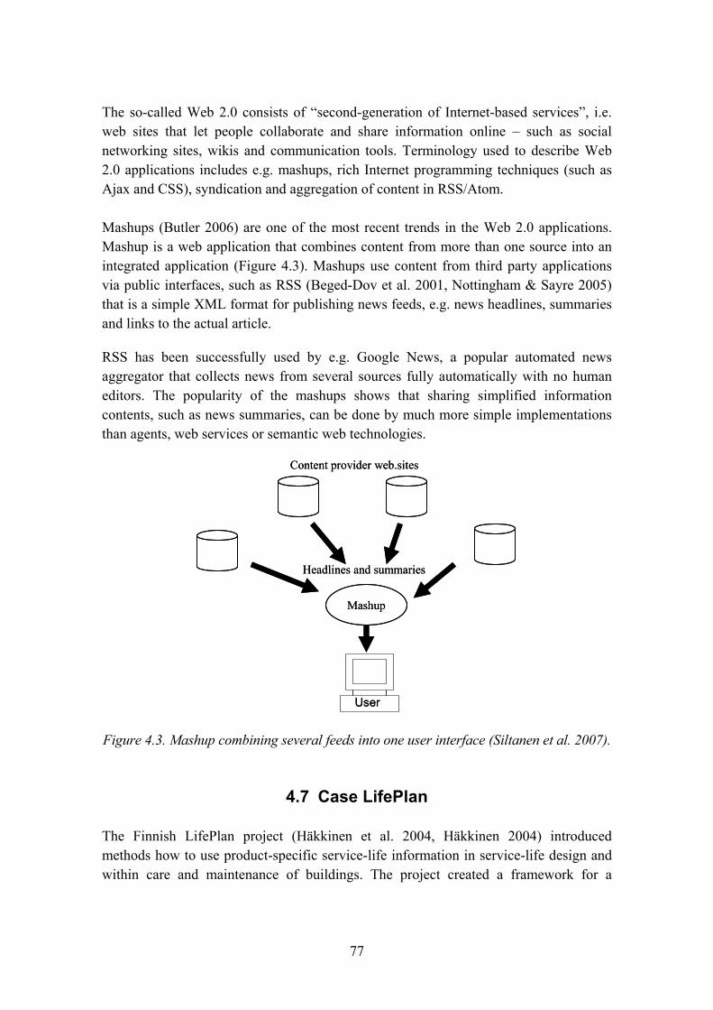
77
The so-called Web 2.0 consists of �second-generation of Internet-based services�, i.e. web sites that let people collaborate and share information online � such as social networking sites, wikis and communication tools. Terminology used to describe Web 2.0 applications includes e.g. mashups, rich Internet programming techniques (such as Ajax and CSS), syndication and aggregation of content in RSS/Atom.
Mashups (Butler 2006) are one of the most recent trends in the Web 2.0 applications. Mashup is a web application that combines content from more than one source into an integrated application (Figure 4.3). Mashups use content from third party applications via public interfaces, such as RSS (Beged-Dov et al. 2001, Nottingham & Sayre 2005) that is a simple XML format for publishing news feeds, e.g. news headlines, summaries and links to the actual article.
RSS has been successfully used by e.g. Google News, a popular automated news aggregator that collects news from several sources fully automatically with no human editors. The popularity of the mashups shows that sharing simplified information contents, such as news summaries, can be done by much more simple implementations than agents, web services or semantic web technologies.
Mashup
Content provider web.sites
Headlines and summaries
User
Mashup
Content provider web.sites
Headlines and summaries
User
Figure 4.3. Mashup combining several feeds into one user interface (Siltanen et al. 2007).
4.7 Case LifePlan
The Finnish LifePlan project (Häkkinen et al. 2004, Häkkinen 2004) introduced methods how to use product-specific service-life information in service-life design and within care and maintenance of buildings. The project created a framework for a
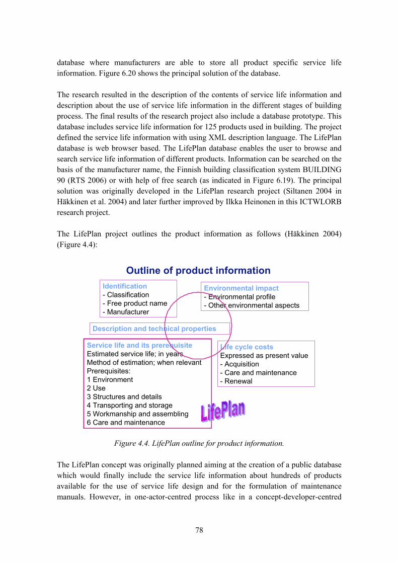
78
database where manufacturers are able to store all product specific service life information. Figure 6.20 shows the principal solution of the database.
The research resulted in the description of the contents of service life information and description about the use of service life information in the different stages of building process. The final results of the research project also include a database prototype. This database includes service life information for 125 products used in building. The project defined the service life information with using XML description language. The LifePlan database is web browser based. The LifePlan database enables the user to browse and search service life information of different products. Information can be searched on the basis of the manufacturer name, the Finnish building classification system BUILDING 90 (RTS 2006) or with help of free search (as indicated in Figure 6.19). The principal solution was originally developed in the LifePlan research project (Siltanen 2004 in Häkkinen et al. 2004) and later further improved by Ilkka Heinonen in this ICTWLORB research project.
The LifePlan project outlines the product information as follows (Häkkinen 2004) (Figure 4.4):
Outline of product informationIdentification- Classification- Free product name- Manufacturer
Description and technical properties
Service life and its prerequisiteEstimated service life; in yearsMethod of estimation; when relevantPrerequisites:1 Environment2 Use3 Structures and details4 Transporting and storage5 Workmanship and assembling6 Care and maintenance
Environmental impact- Environmental profile- Other environmental aspects
Life cycle costsExpressed as present value- Acquisition- Care and maintenance- Renewal
Figure 4.4. LifePlan outline for product information.
The LifePlan concept was originally planned aiming at the creation of a public database which would finally include the service life information about hundreds of products available for the use of service life design and for the formulation of maintenance manuals. However, in one-actor-centred process like in a concept-developer-centred
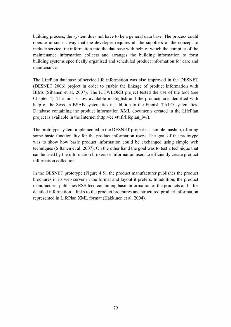
79
building process, the system does not have to be a general data base. The process could operate in such a way that the developer requires all the suppliers of the concept to include service life information into the database with help of which the compiler of the maintenance information collects and arranges the building information to form building systems specifically organised and scheduled product information for care and maintenance.
The LifePlan database of service life information was also improved in the DESNET (DESNET 2006) project in order to enable the linkage of product information with BIMs (Siltanen et al. 2007). The ICTWLORB project tested the use of the tool (see Chapter 4). The tool is now available in English and the products are identified with help of the Sweden BSAB systematics in addition to the Finnish TALO systematics. Database containing the product information XML documents created in the LifePlan project is available in the Internet (http://ce.vtt.fi/lifeplan_iw/).
The prototype system implemented in the DESNET project is a simple mashup, offering some basic functionality for the product information users. The goal of the prototype was to show how basic product information could be exchanged using simple web techniques (Siltanen et al. 2007). On the other hand the goal was to test a technique that can be used by the information brokers or information users to efficiently create product information collections.
In the DESNET prototype (Figure 4.5), the product manufacturer publishes the product brochures in its web server in the format and layout it prefers. In addition, the product manufacturer publishes RSS feed containing basic information of the products and � for detailed information � links to the product brochures and structured product information represented in LifePlan XML format (Häkkinen et al. 2004).

80
Figure 4.5. DESNET prototype allows the information user to read and import product information from manufacturer�s web server or from information broker�s server.
Since the product supplier offers summary of the product information in RSS format, it is easy to implement mashup tools that enable the users to make own collections of the preferred product catalogues. Mashup tool can be provided by the information broker that can collect lists of available product summary feeds and create user interface suitable for the information users needs. The information broker can also validate the product information if needed.
The links contained RSS feed can be used for automatically locating the detailed information of the selected products. The detailed information can when be imported into the user�s applications, assuming of course that appropriate data import interfaces have been implemented.
User interface shown in Figure 4.6 is a general purpose user interface, implemented for combining news feeds, and it does not serve product information user optimally. In the DESNET prototype a simple product information aggregator implementing more advance functionality was created. In the DESNET prototype, the user can select product data RSS feeds from the suppliers he/she prefers and the information is shown on web browser user interface. The user can see up-to-date product information summaries on the browser user
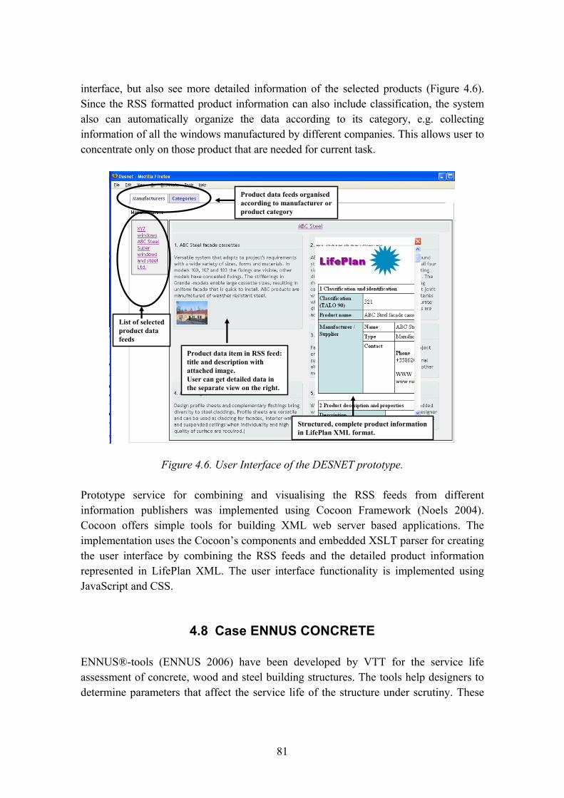
81
interface, but also see more detailed information of the selected products (Figure 4.6). Since the RSS formatted product information can also include classification, the system also can automatically organize the data according to its category, e.g. collecting information of all the windows manufactured by different companies. This allows user to concentrate only on those product that are needed for current task.
List of selectedproduct datafeeds
Product data feeds organisedaccording to manufacturer orproduct category
Product data item in RSS feed:title and description withattached image.User can get detailed data in the separate view on the right.
Structured, complete product informationin LifePlan XML format.
Figure 4.6. User Interface of the DESNET prototype.
Prototype service for combining and visualising the RSS feeds from different information publishers was implemented using Cocoon Framework (Noels 2004). Cocoon offers simple tools for building XML web server based applications. The implementation uses the Cocoon�s components and embedded XSLT parser for creating the user interface by combining the RSS feeds and the detailed product information represented in LifePlan XML. The user interface functionality is implemented using JavaScript and CSS.
4.8 Case ENNUS CONCRETE
ENNUS®-tools (ENNUS 2006) have been developed by VTT for the service life assessment of concrete, wood and steel building structures. The tools help designers to determine parameters that affect the service life of the structure under scrutiny. These
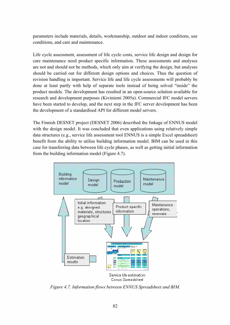
82
parameters include materials, details, workmanship, outdoor and indoor conditions, use conditions, and care and maintenance.
Life cycle assessment, assessment of life cycle costs, service life design and design for care maintenance need product specific information. These assessments and analyses are not and should not be methods, which only aim at verifying the design, but analyses should be carried out for different design options and choices. Thus the question of revision handling is important. Service life and life cycle assessments will probably be done at least partly with help of separate tools instead of being solved �inside� the product models. The development has resulted in an open-source solution available for research and development purposes (Kiviniemi 2005a). Commercial IFC model servers have been started to develop, and the next step in the IFC server development has been the development of a standardised API for different model servers.
The Finnish DESNET project (DESNET 2006) described the linkage of ENNUS model with the design model. It was concluded that even applications using relatively simple data structures (e.g., service life assessment tool ENNUS is a simple Excel spreadsheet) benefit from the ability to utilise building information model. BIM can be used in this case for transferring data between life cycle phases, as well as getting initial information from the building information model (Figure 4.7).
Figure 4.7. Information flows between ENNUS Spreadsheet and BIM.
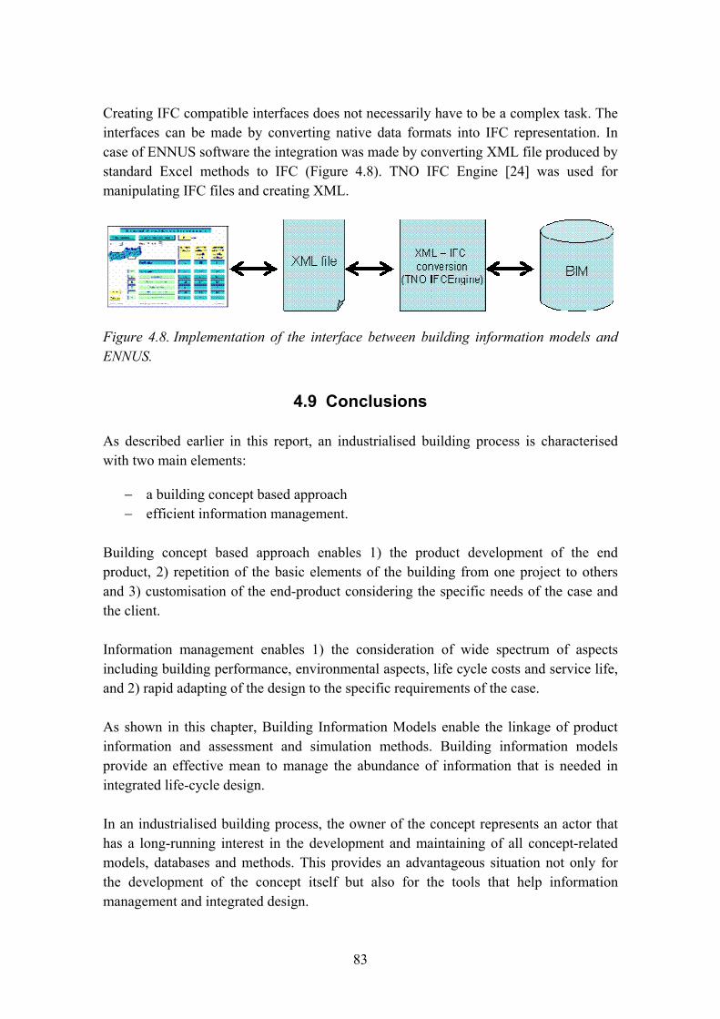
83
Creating IFC compatible interfaces does not necessarily have to be a complex task. The interfaces can be made by converting native data formats into IFC representation. In case of ENNUS software the integration was made by converting XML file produced by standard Excel methods to IFC (Figure 4.8). TNO IFC Engine [24] was used for manipulating IFC files and creating XML.
Figure 4.8. Implementation of the interface between building information models and ENNUS.
4.9 Conclusions
As described earlier in this report, an industrialised building process is characterised with two main elements:
− a building concept based approach − efficient information management.
Building concept based approach enables 1) the product development of the end product, 2) repetition of the basic elements of the building from one project to others and 3) customisation of the end-product considering the specific needs of the case and the client.
Information management enables 1) the consideration of wide spectrum of aspects including building performance, environmental aspects, life cycle costs and service life, and 2) rapid adapting of the design to the specific requirements of the case.
As shown in this chapter, Building Information Models enable the linkage of product information and assessment and simulation methods. Building information models provide an effective mean to manage the abundance of information that is needed in integrated life-cycle design.
In an industrialised building process, the owner of the concept represents an actor that has a long-running interest in the development and maintaining of all concept-related models, databases and methods. This provides an advantageous situation not only for the development of the concept itself but also for the tools that help information management and integrated design.
84
References
Bazjanac, V. 2004. Building energy performance simulation as part of interoperable software environments. University of California.
Beged-Dov, G., Brickley, D., Dornfest, R., Davis, I., Dodds, L., Eisenzopf, J., Galbraith, D., Guha, R. V., MacLeod, K., Miller, E., Swartz, A. & van der Vlist, E. 2001. RSS 1.0 specification. http://purl.org/rss/1.0/spec.
Berners-Lee, T., Hendler, J. & Lassila, O. 2001. The Semantic Web. Scientific American, Vol. 284, No. 34–43, May 2001.
Butler, D. 2006. Mashups Mix Data into Global Service 2006. Nature, Vol. 459, No. 7072, pp. 6–7.
DESNET. 2006. Potentials of networking in the application of ICT solutions for life cycle designs of buildings. Research project coordinated by Tarja Häkkinen in the Finnish research programme KITARA. http://www.aka.fi/index.asp?id=04B8272BF7F64093A4991A2A61E5B474&data=1,00308B787886459385F296A5AFD4FA74,AF4A53EF7BF54A488FA4E04F83EACB0E&tabletarget=data_1&laytmp=aka_fi_sisa.
ENNUS. 2006. ENNUS methods for service life estimation of roofs and outdoor walls. VTT Materials and Building. http://virtual.vtt.fi/environ/ennus_e.html.
Finne, C. 2003. How the Internet is Changing the Role of Construction Information Middlemen. ITcon, Vol. 8, Special Issue eWork and eBusiness, pp. 397–412. http://www.itcon.org/2003/28.
Fischer, M. & Kam, C. 2002. PM4D Final Report. CIFE Technical Report Number 143. Stanford University, USA.
Fu, C., Aouad, G., Lee, A., Marshall-Ponting, A. & Wu, S. 2006. IFC model viewer to support nD model application. Automation in Construction, Vol. 15, Issue 2, March 2006, pp. 178–185.
Gudnason, G., Hyvärinen, J., Finne, C. & Larsson, S. 2005. eProCon: Electronic Product Information in Construction. 22nd CIB W78 Conference, Dresden 2005.

85
Häkkinen, T. 2004. Service Life Planning � from theory to practical processes. 2nd int. symposium. Integrated life cycle design. Proceedings. Published by RIL (Association of Finnish Civil Engineers). Kuopio, Finland. 6 p.
Häkkinen, T. 2007. Sustainable building related new demands for product information and product model based design. ITcon, Vol. 12, pp. 19�37.
Häkkinen, T., Vares, S. & Siltanen, P. 2004. Service Life Information of Building Products. (In Finnish.) VTT Research reports 2231. Espoo: VTT.
ISO. 2006. ISO TS 21929. Building Construction � Sustainability in Building Construction � Sustainability Indicators. Part 1 � Framework for the development of indicators for buildings.
Karstila, K. & Seren, K. 2005. Tiedonsiirron käyttötapaus: Tuotekirjastotiedon siirto. (In Finnish.) ProIT project document, available online: http://virtual.vtt.fi/proit/julkiset_tulokset/proit_dexuc_tuotelib_versio_10_2005_01_31.pdf (accessed 30.8.2006).
Kiviniemi, A. 2005a. Integrated product models in life-cycle evaluation and management of the built environment. In: Proceeding of the International workshop on lifetime engineering of civil infrastructure. Ube, Yamaguchi, Japan, 9�11 Nov. 2005. 18 p.
Kiviniemi, A. 2005b. Requirements Management Interface to building product models. CIFE Technical report 161. March 2005. Stanford University. 328 p.
Kong, S., Li, H. & Shen, L. 2001. An Internet-based Electronic Product Catalogue of Construction Materials. Construction Innovation, Vol. 1, pp. 245�257.
Kong, S. C. W., Li, H., Hung, T., Anumba, C. J. & Chen, Z. 2005. Web services enhanced interoperable construction products catalogue. Automation in Construction, Vol. 14, pp. 343�352.
Lima, C., Stephens, J. & Böhms, M. 2003. The bcXML: Supporting eCommerce and Knowledge Management in the Construction Industry. ITcon, Vol. 8, Special Issue eWork and eBusiness, pp. 293�308. http://www.itcon.org/2003/22.
Niemioja, S. 2005. Architect�s product model based design. Guidelines. ProIT Product model data in construction process. (In Finnish.) Confederation of Finnish Construction Industries RT. 57 p.

86
Noels, S. 2004. Cocoon: XML and Web Application Development. XML Europe 2004, Amsterdam.
Nottingham, M. & Sayre, R. 2005. The Atom Syndication Format. Internet proposed standard RFC 4287.
OWL Web Ontology Language Overview. 2004. W3C Recommendation, available online http://www.w3.org/TR/owl-features, accessed 30.8.2006.
ProIT. 2005. ProIT, Product model data in the construction process, coordinated by the Confederation of Finnish construction industries. http://www.vtt.fi/rte/cmp/projects/proit_eng/indexe.htm.
RDF Primer. 2004. W3C Recommendation, available online http://www.w3.org/TR/rdf-primer, accessed 30.8.2006.
RTS. 2006. Building 90. The Finnish Building Classification system. http://www.rts.fi/talo-nimikkeisto/building90.pdf.
Shailesh, J. & Godfried, A. 2003. A methodology for supporting product selection from e-cataloges. ITCon, Vol. 8, pp. 383�396.
Siltanen, P. 2004. LifePlan database. Chapter 3 in Häkkinen, T., Vares, S. & Siltanen, P. Service life information of building products. VTT Research reports 2231. Espoo: VTT. 54 p. + app. 32 p. (In Finnish.)
Siltanen, P., Pärnanen, A. & Vares, S. 2007. RSS in Publishing Building Product Information. Manuscript for ITcon. 11 p.
87
Chapter 5
Author Åse Togerö
Contents
5. Toolbox � Methodologies and tools for ILC-Design and ILC-Customisation & Configuration .............................................................................................................88 5.1 Introduction ......................................................................................................88 5.2 Integrated life cycle design...............................................................................88 5.3 The traditional building process .......................................................................90 5.4 The industrialised building process ..................................................................91 5.5 The Toolbox � examples of tools to use in an ILC Design or
Customisation/Configuration ...........................................................................95 5.6 Description of tools ..........................................................................................98 References................................................................................................................107
88
5. Toolbox � Methodologies and tools for ILC-Design and ILC-Customisation & Configuration
5.1 Introduction
One of the main objectives of the co-operation project ICTWLORB is to develop an ICT based toolbox for integrated life cycle design. There is a strong need of finding new ways of working in and with the building process; changing from a short term focus to a life cycle based planning process. This demands not only computer-based tools for handling technical and qualitative issues in a life cycle based perspective but also new ways of handling information and data created by these tools. To facilitate the use of these tools they ought to be developed, consolidated to each other and, where possible, linked by ICT.
This chapter aims at collecting and describing ICT based tools for life cycle design that are suitable for use in a rational building process and that also eventually could be used in for example Building Information Models or other models suitable for an industrialised building process. Examples of tools will be given for different types of building processes, to illustrate the different way of working in an industrialised process.
There are many tools that could be brought up, but the purpose of the subproject in ICTWLORB has not been to find the best available tools, as this demands a very complex and time consuming valuation process, with risks of choices eventually made on biased opinions in any case. Instead the project group has focused on collecting a series of tools which are well suitable and functional for the purposes mentioned earlier, and of which the project members have good knowledge and experience.
5.2 Integrated life cycle design
As written earlier in this report the European Working Group on Sustainable Construction (Sustainable Construction 2004) states that good value for the community requires consideration of the building�s full life cycle. Sustainable development implies efforts to prolong the life of existing structures and the utilisation of the original materials in a structure. Trinius and Sjöström (2005) conclude that to be able to reach a sustainable building process, the life cycle aspects must be considered, and not only considered but also quantified and compared to a common reference. In other words the economical, environmental and technical building performance during a long time horizon must be considered; in the programme phase when setting the requirements, in the design phase when creating and comparing different solutions and in the

89
construction phase when the ideas of the wished performance must be understood and realised. This is what is normally referred to as life cycle design (with the word �design� included as this is the phase were the life cycle performance of different solutions is estimated). As a result of this interpretation, integrated life cycle design comprises a wider concept than �design�, and in the list of tools provided later in this chapter, not only tools to use during the design phase are listed.
Which aspects of building performances should be analysed during an ILCD? The question is not easy to answer since there are different views in the literature. Öberg (2005) refers to the EU Construction Product Directive (EU 1988) where six requirements are stated:
− mechanical resistance and stability − safety in case of fire − hygiene, health and the environment − safety in use − protection against noise − energy economy and heat retention.
Asko Sarja, who developed the concept of ILCD (Sarja et al. 1999), explains the idea like this:
�When incorporating an environmental viewpoint into the design of materials and structures, the entire context of the design process must be reconsidered in order to integrate environmental aspects into a set of other design aspects. This kind of process is known as �Integrated Life Cycle Design� and its aim consists of assimilating, in a practical manner, the multiple requirements of functionality, economy, performance, resistance, aesthetics and ecology all into the technical specifications and detailed designs of materials and structures.�
In this chapter, not all aspects mentioned above are included. Meanwhile Sarja concentrated on including quality related aspects such as ecology, aesthetics etc. in a traditional process where mechanical function is the most important issue during the design, and Öberg included mechanical function, fire resistance and acoustics as examples of functionality, the project group in ICTWLORB has concentrated on the aspects that will be of most interest for the client and the user during the life of the building. That is, meanwhile the mechanical function is of great importance for the constructor, it is more or less taken for granted by the client and the end-user. Instead, aspects that vary considerably during the life cycle and have economical or qualitative impacts during time are in the focus for the tools listed here. The chosen aspects are therefore:

90
� economy � environmental impact � energy performance � service life / durability � moisture safety � risk estimation.
Integrated life cycle design (ILCD) implies that an integration of the different agreed targets should be made � so that the different requirements do not contradict each other but seen in a holistic perspective. Further, when deciding which solutions to use in a building project, the decision should be made in a systematic way, for example by using a decision supporting tool (Öberg 2005).
The first idea of an integrated design (the holistic perspective) is crucial for a successful total outcome of the project, but in contrast to most other tasks when carrying out an ILCD, there are not so many helping tools in that field today. Thus it is important that the persons involved in the process fully understands the ideas of the integration. In short the following aspects should be addressed by the actors of the process:
− What types of performances (i.e. technical, economical and environmental) could interact with, or contradict each other during the life cycle of the building?1
− Is every life cycle aspect only considered once, or is there a risk of over-accounting when using different tools for the estimation of life cycle performance?1
− What should be the time horizon when estimating the different performances?
5.3 The traditional building process
The traditional building process is a process which involves many different actors linked together in a very typical pattern formed by the different phases of the process, see Figure 5.1: a feasibility study, a programme phase (where requirements of the building are formulated), a design phase where the project specific instructive documents are carried out, a construction phase including work on site and in factory, final control of the performed construction, and � ideally � an evaluation after a few years of use.
1 A certain help with this complex question can be found in Mats Öberg�s thesis (2005), page 122.
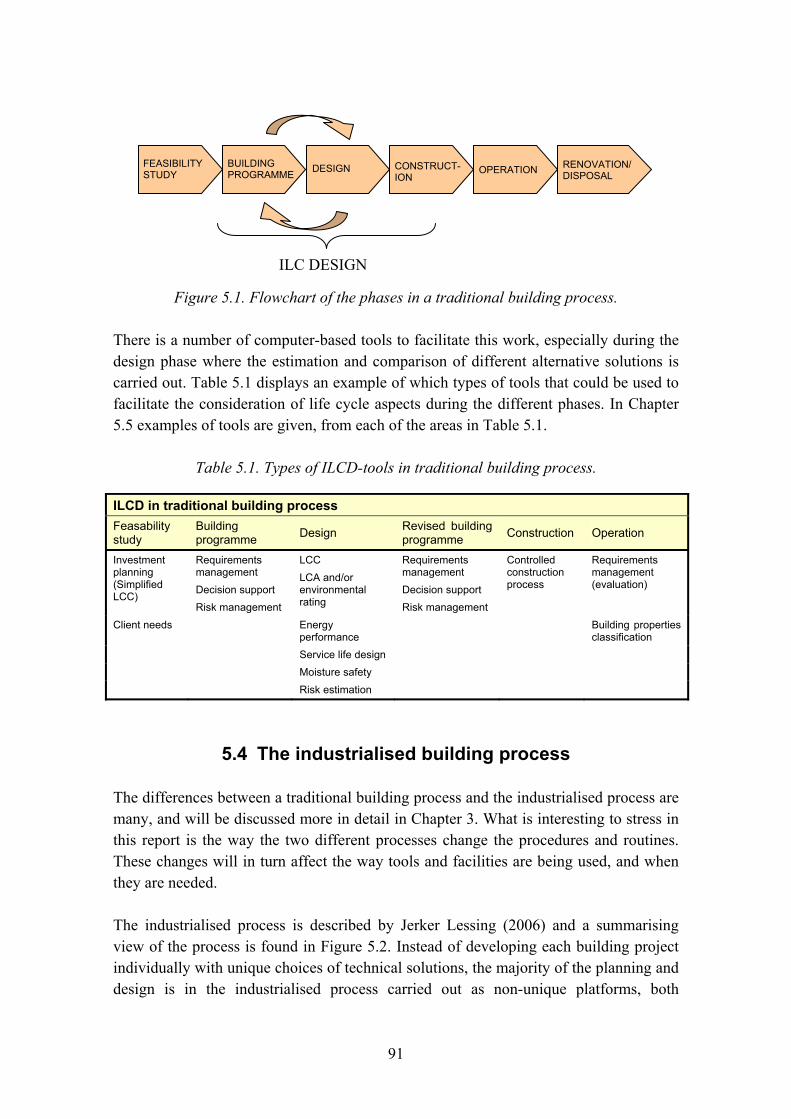
91
Figure 5.1. Flowchart of the phases in a traditional building process.
There is a number of computer-based tools to facilitate this work, especially during the design phase where the estimation and comparison of different alternative solutions is carried out. Table 5.1 displays an example of which types of tools that could be used to facilitate the consideration of life cycle aspects during the different phases. In Chapter 5.5 examples of tools are given, from each of the areas in Table 5.1.
Table 5.1. Types of ILCD-tools in traditional building process.
ILCD in traditional building process Feasability study
Building programme Design Revised building
programme Construction Operation
Investment planning (Simplified LCC)
Requirements management Decision support Risk management
LCC LCA and/or environmental rating
Requirements management Decision support Risk management
Controlled construction process
Requirements management (evaluation)
Client needs Energy performance
Building properties classification
Service life design Moisture safety Risk estimation
5.4 The industrialised building process
The differences between a traditional building process and the industrialised process are many, and will be discussed more in detail in Chapter 3. What is interesting to stress in this report is the way the two different processes change the procedures and routines. These changes will in turn affect the way tools and facilities are being used, and when they are needed.
The industrialised process is described by Jerker Lessing (2006) and a summarising view of the process is found in Figure 5.2. Instead of developing each building project individually with unique choices of technical solutions, the majority of the planning and design is in the industrialised process carried out as non-unique platforms, both
DESIGN BUILDING PROGRAMME OPERATION RENOVATION/
DISPOSAL CONSTRUCT-ION
FEASIBILITY STUDY
ILC DESIGN
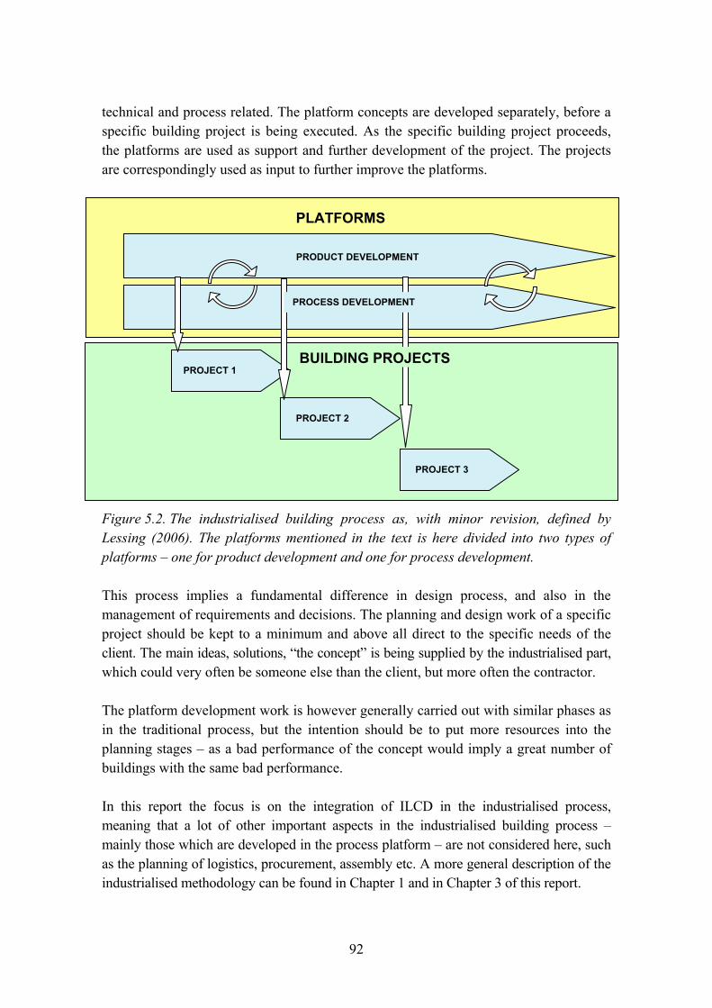
92
technical and process related. The platform concepts are developed separately, before a specific building project is being executed. As the specific building project proceeds, the platforms are used as support and further development of the project. The projects are correspondingly used as input to further improve the platforms.
Figure 5.2. The industrialised building process as, with minor revision, defined by Lessing (2006). The platforms mentioned in the text is here divided into two types of platforms � one for product development and one for process development.
This process implies a fundamental difference in design process, and also in the management of requirements and decisions. The planning and design work of a specific project should be kept to a minimum and above all direct to the specific needs of the client. The main ideas, solutions, �the concept� is being supplied by the industrialised part, which could very often be someone else than the client, but more often the contractor.
The platform development work is however generally carried out with similar phases as in the traditional process, but the intention should be to put more resources into the planning stages � as a bad performance of the concept would imply a great number of buildings with the same bad performance.
In this report the focus is on the integration of ILCD in the industrialised process, meaning that a lot of other important aspects in the industrialised building process � mainly those which are developed in the process platform � are not considered here, such as the planning of logistics, procurement, assembly etc. A more general description of the industrialised methodology can be found in Chapter 1 and in Chapter 3 of this report.
PROJECT 1
PROJECT 2
PROJECT 3
PLATFORMS
PRODUCT DEVELOPMENT
BUILDING PROJECTS
PROCESS DEVELOPMENT

93
With regards to the increased resources during early stages, as described above, the prerequisites to implement ILCD should be better in an industrialized building process than in the traditional process, but the implementation is also enhanced by the phenomena of industrialization: i.e. the effects of repetition, process control, feedback of experience etc.
Instead of the feasibility study and the programme phase carried out by the client in a traditional process, a similar process is carried out by the platform developer, i.e. a planning process including market analysis and a programme phase where wished performances are set, see Figure 5.3.
ILC DESIGN
CONCEPTDESIGN
MARKET ANALYSIS EVALUATIONWISHED
PERFORMANCERANKING/ DECISION
SUPPORT/PLANNING OF PROCESS
PLATFORMS
ILC DESIGN
CONCEPTDESIGN
MARKET ANALYSIS EVALUATIONWISHED
PERFORMANCERANKING/ DECISION
SUPPORT/PLANNING OF PROCESS
CONCEPTDESIGN
MARKET ANALYSIS EVALUATIONWISHED
PERFORMANCERANKING/ DECISION
SUPPORT/PLANNING OF PROCESS
PLATFORMSPLATFORMS
Figure 5.3. Integrated life cycle design in the development of concepts.
The platform concept owner then thoroughly design the concept, estimating the performance by using advanced tools and means. One big advantage with the industrialised process is the possibility to invest time and money to find a good performance, something that is difficult in a traditional building process for each unique project � it is time consuming and therefore a costly procedure (even though it may be profitable in a life cycle perspective).
After the creation of different solutions a decision of which alternatives to use follow, and should be carried out by a structural ranking methodology or decision support tool, see Table 5.2 which shows the type of tools needed in the different phases. Note that the decision taking part during this stage is not the client but the concept-owner of the industrialised actor, changing the power balance between the different actors and giving the concept owner a unique position in the building industry. (Also note that in an industrialized process, the technical solutions might very well be dependent on market-based situations, like the actual supply of components. Long delivery times might results in another technical solution.)

94
Figure 5.4. The integrated life cycle customisation in a building project, emerging from a platform concept.
In Figure 5.4 the process in an industrialised building project is schematically displayed. As pointed out earlier in this report, the majority of the planning and design should not be carried out during the building project itself. But even if kept to a minimum, there will very often be changes to the concept, due to the needs and wishes of the unique client, and of other circumstances such as ground conditions, local regulations etc. This will affect the concept and therefore the economical, environmental and technical performances as well. To separate this process from the extensive work carried out during the development of platforms (ILC Design), it may be called ILC Customisation. The idea is to consider life cycle aspects, but in a less thorough way, using key figures and statistic to discuss wit the client the way different alternatives is affecting the life cycle performance.
Tables 5.2 and 5.3 display an example of which types of tools that could be used to facilitate the consideration of life cycle aspects during the different phases, in the ILC Design and in ILC Customisation. In Chapter 5.5 examples of tools are given, from each of the areas in Tables 5.2 and 5.3.
Table 5.2. Type of tools to use for ILC-Design in the development of the product.
ILC Design in industrialised building process
Market analysis
Wished performance
Design Decision of solutions
Evaluation
Investment planning (Simplified LCC)
Requirements management Decision support Risk management
LCC LCA and/or environmental rating Energy performance
Requirements management Decision support Risk management
Requirements management (measuring performance)
Service life design
Moisture safety
Risk estimation
PROJECT
SYSTEM DESIGN
SCHEMATIC DESIGN
CLIENT NEEDS /PROGRAM OPERATION ASSEMBLYMANUFACTURE
ILC CUSTOMISATION & CONFIGURATION
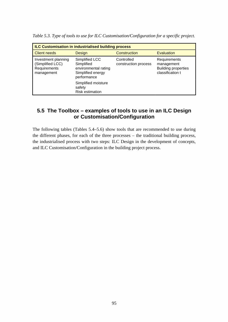
95
Table 5.3. Type of tools to use for ILC Customisation/Configuration for a specific project.
ILC Customisation in industrialised building process
Client needs Design Construction Evaluation
Investment planning (Simplified LCC) Requirements management
Simplified LCC Simplified environmental rating Simplified energy performance
Controlled construction process
Requirements management Building properties classification t
Simplified moisture safety Risk estimation
5.5 The Toolbox – examples of tools to use in an ILC Design or Customisation/Configuration
The following tables (Tables 5.4–5.6) show tools that are recommended to use during the different phases, for each of the three processes – the traditional building process, the industrialised process with two steps: ILC Design in the development of concepts, and ILC Customisation/Configuration in the building project process.
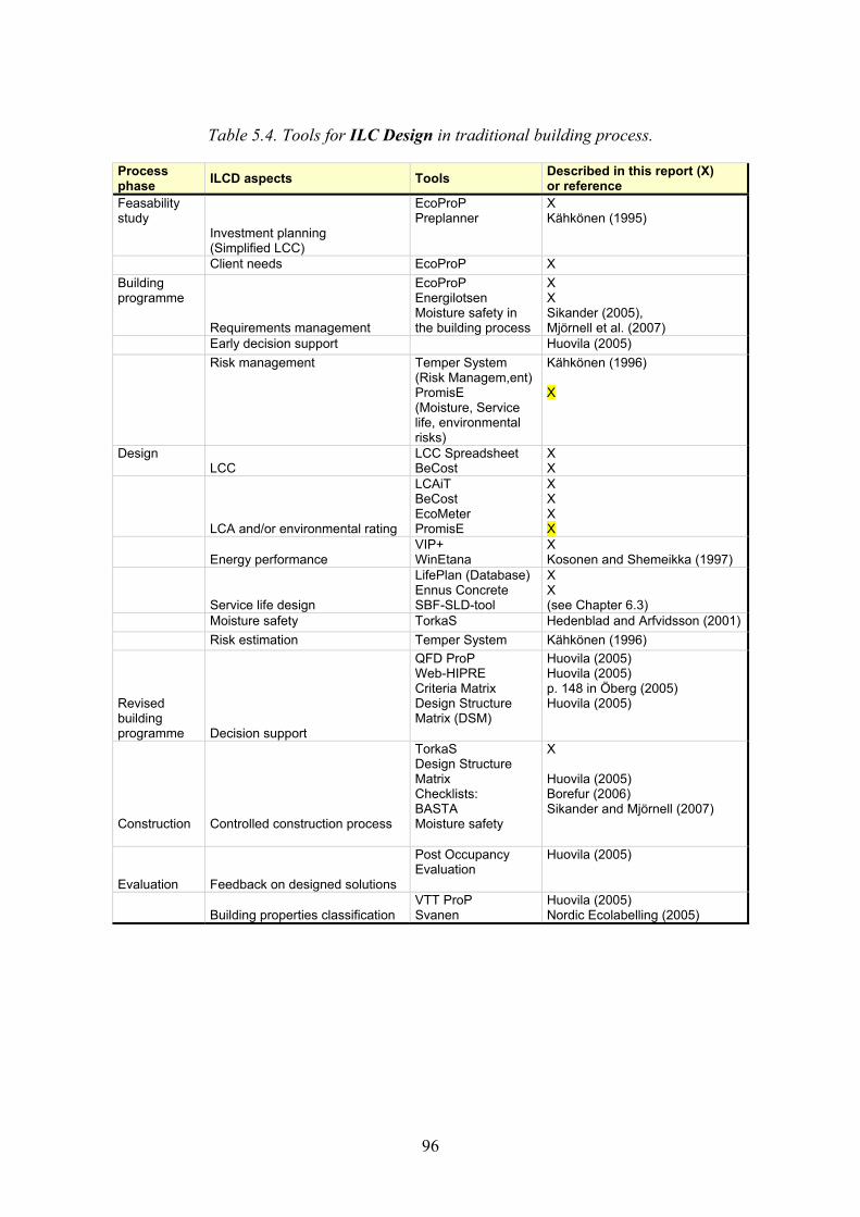
96
Table 5.4. Tools for ILC Design in traditional building process.
Process phase ILCD aspects Tools Described in this report (X)
or reference Feasability study
Investment planning (Simplified LCC)
EcoProP Preplanner
X Kähkönen (1995)
Client needs EcoProP X Building programme
Requirements management
EcoProP Energilotsen Moisture safety in the building process
X X Sikander (2005), Mjörnell et al. (2007)
Early decision support Huovila (2005) Risk management Temper System
(Risk Managem,ent)PromisE (Moisture, Service life, environmental risks)
Kähkönen (1996) X
Design LCC
LCC Spreadsheet BeCost
X X
LCA and/or environmental rating
LCAiT BeCost EcoMeter PromisE
X X X X
Energy performance
VIP+ WinEtana
X Kosonen and Shemeikka (1997)
Service life design
LifePlan (Database)Ennus Concrete SBF-SLD-tool
X X (see Chapter 6.3)
Moisture safety TorkaS Hedenblad and Arfvidsson (2001)
Risk estimation Temper System Kähkönen (1996) Revised building programme Decision support
QFD ProP Web-HIPRE Criteria Matrix Design Structure Matrix (DSM)
Huovila (2005) Huovila (2005) p. 148 in Öberg (2005) Huovila (2005)
Construction
Controlled construction process
TorkaS Design Structure Matrix Checklists: BASTA Moisture safety
X Huovila (2005) Borefur (2006) Sikander and Mjörnell (2007)
Evaluation
Feedback on designed solutions
Post Occupancy Evaluation
Huovila (2005)
Building properties classification
VTT ProP Svanen
Huovila (2005) Nordic Ecolabelling (2005)
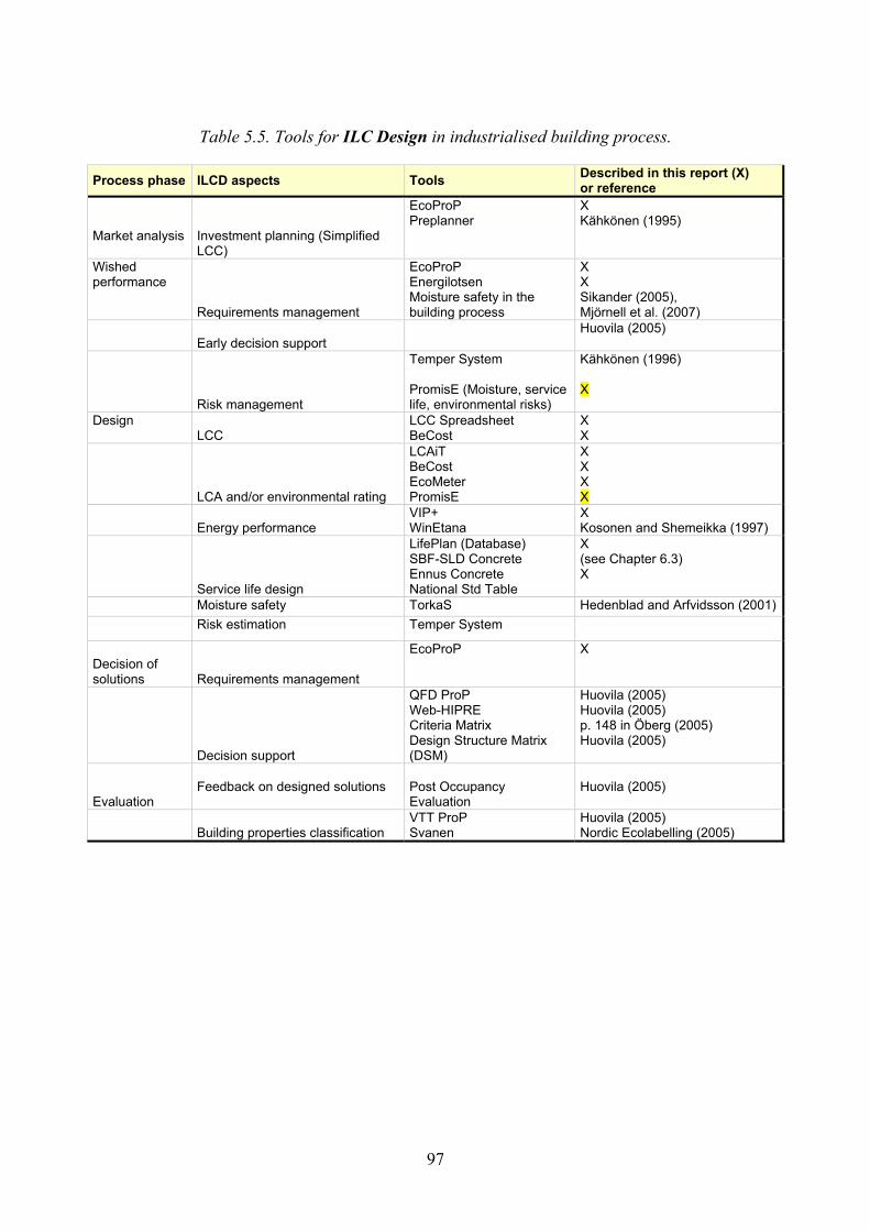
97
Table 5.5. Tools for ILC Design in industrialised building process.
Process phase ILCD aspects Tools Described in this report (X) or reference
Market analysis
Investment planning (Simplified LCC)
EcoProP Preplanner
X Kähkönen (1995)
Wished performance
Requirements management
EcoProP Energilotsen Moisture safety in the building process
X X Sikander (2005), Mjörnell et al. (2007)
Early decision support
Huovila (2005)
Risk management
Temper System PromisE (Moisture, service life, environmental risks)
Kähkönen (1996) X
Design LCC
LCC Spreadsheet BeCost
X X
LCA and/or environmental rating
LCAiT BeCost EcoMeter PromisE
X X X X
Energy performance
VIP+ WinEtana
X Kosonen and Shemeikka (1997)
Service life design
LifePlan (Database) SBF-SLD Concrete Ennus Concrete National Std Table
X (see Chapter 6.3) X
Moisture safety TorkaS Hedenblad and Arfvidsson (2001) Risk estimation Temper System
Decision of solutions Requirements management
EcoProP X
Decision support
QFD ProP Web-HIPRE Criteria Matrix Design Structure Matrix (DSM)
Huovila (2005) Huovila (2005) p. 148 in Öberg (2005) Huovila (2005)
Evaluation
Feedback on designed solutions
Post Occupancy Evaluation
Huovila (2005)
Building properties classification
VTT ProP Svanen
Huovila (2005) Nordic Ecolabelling (2005)

98
Table 5.6. Tools for ILC Customisation or Configuration in industrialised building process.
Process phase ILCD aspectss Tools Described in this report (X)
or reference
Client needs
Investment planning (Simplified LCC)
Kalkylsnurran EcoProP Preplanner iBuild
Kronudd (2007) X Kähkönen (1995) Huovila (2005)
Design Moisture Safety Moisture safety in
the building process Sikander (2005), Mjörnell et al. (2007)
Environmental rating
PromisE
X
Risk management Temper System PromisE (Moisture, Service life, environmental risks)
Kähkönen (1996) X
Moisture safety TorkaS Hedenblad and Arfvidsson (2001)
Construction
Controlled building process
TorkaS Checklists: BASTA Moisture safety
Hedenblad and Arfvidsson (2001) Datakustik (retr. 2007) Sikander and Mjörnell (2007)
Evaluation
Building properties classification
VTT ProP Svanen
Huovila (2005) Nordic Ecolabelling (2005)
5.6 Description of tools
Some of the tools in Chapter 5.5 are described more in detail, as they represent good examples of tools to use in an ILC process. The described tools are listed in alphabetical order in a format that makes them easy to compare and that facilitate eventual listing in a database. The form contains the name, purpose, intended user, functions, inputs, outputs, access, sources and user rights.

99
Name BECOST � Tool for Life Cycle Assessment of building structures and whole buildings (still only in Finnish)
Purpose of use: to examine the ecological effect of building choices related to materials used and service life of the whole building (designer and constructors use); verifying environmental characteristics' fulfillment, if such has been demanded (designer use); for owners to examine their building's environmental profiles (owner use); checking the affect of care, maintenance and repairing actions on the environment; comparing environmental profiles of structures having the same functional units; and comparing environmental impacts of produced- and competing materials in certain structure or building (use of building material producer).
Intended user Designer, owners, material producers
Description of the functions of the tool The program includes: Environmental profiles, costs and maintenance costs of building materials produced in Finland The structures for designing outdoor walls, indoor walls, roofs, floors, etc. Material quantity calculations Environmental profile calculation for designed structure Result as plot of environmental profile (emissions), energy- and raw-material use, and cost impact for the structure and whole building.
Input information BeCost is an easy to use program � the user should first define the building by making relevant choices, by choosing the structure and materials, by giving the volumes in m2 and by choosing the service life of the building.
Output Environmental profile (emissions, energy- and raw-material use) Life-cycle cost impact.
Access (web address / source) http://ce.vtt.fi/becost
User rights Available through VTT
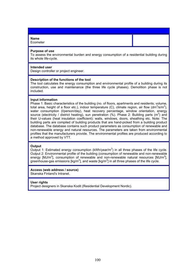
100
Name Ecometer
Purpose of use To assess the environmental burden and energy consumption of a residential building during its whole life-cycle.
Intended user Design controller or project engineer.
Description of the functions of the tool The tool calculates the energy consumption and environmental profile of a building during its construction, use and maintenance (the three life cycle phases). Demolition phase is not included.
Input information Phase 1: Basic characteristics of the building (no. of floors, apartments and residents; volume, total area, height of a floor etc.), indoor temperature (C), climate region, air flow (dm3/s/m2), water consumption (l/person/day), heat recovery percentage, window orientation, energy source (electricity / district heating), sun penetration (%). Phase 2: Building parts (m2) and their U-values (heat insulation coefficient): walls, windows, doors, sheathing etc. Note: The building parts are compiled of building products that are hand-picked from a building product database. The database contains such product parameters as consumption of renewable and non-renewable energy and natural resources. The parameters are taken from environmental profiles that the manufacturers provide. The environmental profiles are produced according to a method approved by VTT.
Output Output 1: Estimated energy consumption (kWh/year/m2) in all three phases of the life cycle. Output 2: Environmental profile of the building (consumption of renewable and non-renewable energy [MJ/m2], consumption of renewable and non-renewable natural resources [MJ/m2], greenhouse-gas emissions [kg/m2], and waste [kg/m2] in all three phases of the life cycle.
Access (web address / source) Skanska Finland's Intranet.
User rights Project designers in Skanska Kodit (Residential Development Nordic).
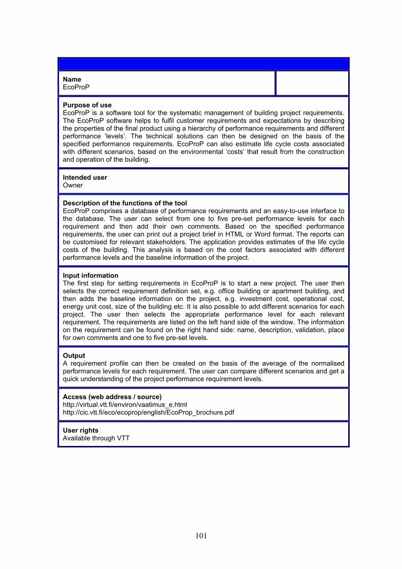
101
Name EcoProP
Purpose of use EcoProP is a software tool for the systematic management of building project requirements. The EcoProP software helps to fulfil customer requirements and expectations by describing the properties of the final product using a hierarchy of performance requirements and different performance �levels�. The technical solutions can then be designed on the basis of the specified performance requirements. EcoProP can also estimate life cycle costs associated with different scenarios, based on the environmental �costs� that result from the construction and operation of the building.
Intended user Owner
Description of the functions of the tool EcoProP comprises a database of performance requirements and an easy-to-use interface to the database. The user can select from one to five pre-set performance levels for each requirement and then add their own comments. Based on the specified performance requirements, the user can print out a project brief in HTML or Word format. The reports can be customised for relevant stakeholders. The application provides estimates of the life cycle costs of the building. This analysis is based on the cost factors associated with different performance levels and the baseline information of the project.
Input information The first step for setting requirements in EcoProP is to start a new project. The user then selects the correct requirement definition set, e.g. office building or apartment building, and then adds the baseline information on the project, e.g. investment cost, operational cost, energy unit cost, size of the building etc. It is also possible to add different scenarios for each project. The user then selects the appropriate performance level for each relevant requirement. The requirements are listed on the left hand side of the window. The information on the requirement can be found on the right hand side: name, description, validation, place for own comments and one to five pre-set levels.
Output A requirement profile can then be created on the basis of the average of the normalised performance levels for each requirement. The user can compare different scenarios and get a quick understanding of the project performance requirement levels.
Access (web address / source) http://virtual.vtt.fi/environ/vaatimus_e.html http://cic.vtt.fi/eco/ecoprop/english/EcoProp_brochure.pdf
User rights Available through VTT

102
Name ENNUS CONCRETE
Purpose of use Assessment of service life of concrete structures exposed to weather conditions Design for required service life (estimated service life > design life)
Intended user Designer of concrete structure
Description of the functions of the tool The ENNUS®-programs has been developed for the service life assessment of building structures for designers. The programs help designers to determine parameters that affect the service life of the structure under scrutiny. These parameters include the following aspects: materials, details, workmanship, outdoor and indoor conditions, use conditions, and care and maintenance. VTT has developed ENNUS® tools for concrete out door walls and balconies, steel facades and roofing, and for wood outdoor walls.
ENNUS® CONCRETE can be purchased from VTT Publication sales.
Input information Materials: Type of cement, strength, max aggregate size, air content, effective water-cement ratio Design, structural details: Thickness of the structure, reinforcement, concrete cover, coating Performance of work: Curing period Exposure to weather: Direction in terms of compass point, geographical location Maintenance: Intervals of inspection and care
Output Estimated service life with regard to frost resistance and carbonation
Access (web address / source) http://virtual.vtt.fi/environ/ennus_e.html Information about the methodology: Vesikari, E. Estimation of service life on concrete facades by the factor approach. Proceedings RILEM PRO 16. Life prediction and aging management of concrete structures. October 16�17, 2000, France. Pp. 15�23. Sources: Punkki, J. Service life design in Finnish concrete code of practice. Proceedings, European Symposium on service life and serviceability of concrete structures ESCS-2006. June 12�14, 2006. Espoo. Pp. 214�219.
User rights Public; Available through VTT

103
Name LCAiT
Purpose of use Calculation of mass and energy balances, and environmental impact assessments, of technical systems, typically life cycle assessments (LCA) of products.
Intended user Because of the huge number of flexible features it is very suitable for the LCA expert, but it is also appropriate for an LCA practitioner that performs less complex LCAs, like for instance an Environmental engineer or even an LCA beginner. An LCA beginner might however need more LCA support, Software user support and Data, which are services that we offer separately. The Design engineer might use the software for simple evaluations, but this requires that a huge number of data sets are included since a desing engineer does not have the time to perform LCIs for materials etc. A combination between a desing engineer and an LCA practioner within the company may be the best solution
Description of the functions of the tool The following main functions are contained: � Defining a new project (e.g. LCA project) and its different product systems in the Workspace
working area � Creating and designing system (i.e. flow chart / process tree) in the Flowchart working area. � Insert input and output flow data for processes, either one by one, or through a flow table
import function � Defining a new substance, a unit, impact assessment characterisation factors etc. in the
Nomenclature working area. � Searching for a data set from available data bases in the Query working area � Management of LCAiT databases � Calculating the inventory and impact assessment results in the Output working area. � Creating reports, e.g. Inventory tables, Impact tables, Impact graphs, (by activity or by life
cycle phase)
Input information If starting with a New activity, inputs are: all relevant inputs and outputs related to the functional output (e.g. 1 kg of cement) of the process under study. For transports, mode of transport, emission profile for the used mode and transport distance are needed. Already made activities are connected in the flow chart to form the modelled system under study.
Output Inputs and outputs for the total modelled system under study, distributed on each activity contained in the system, or aggregated to a user-defined level of aggregation. Inputs ond outputs can be presented in physical flow units as entered (e.g. MJ, kg), or aggregated to potential environmental impacts (e.g. global warming potential units).
Access (web address / source) Chalmers Industriteknik, Chalmers Science Park, 412 88 Göteborg, +46 31 772 4000 Distibuted also by: IVL Swedish Environmental Research Institute Ltd, Box 5302, 400 14 Göteborg, +46 31 725 62 00
User rights Demo version available free of cost; Full version available by licence agreement at a cost; additional data bases can be purchased separately
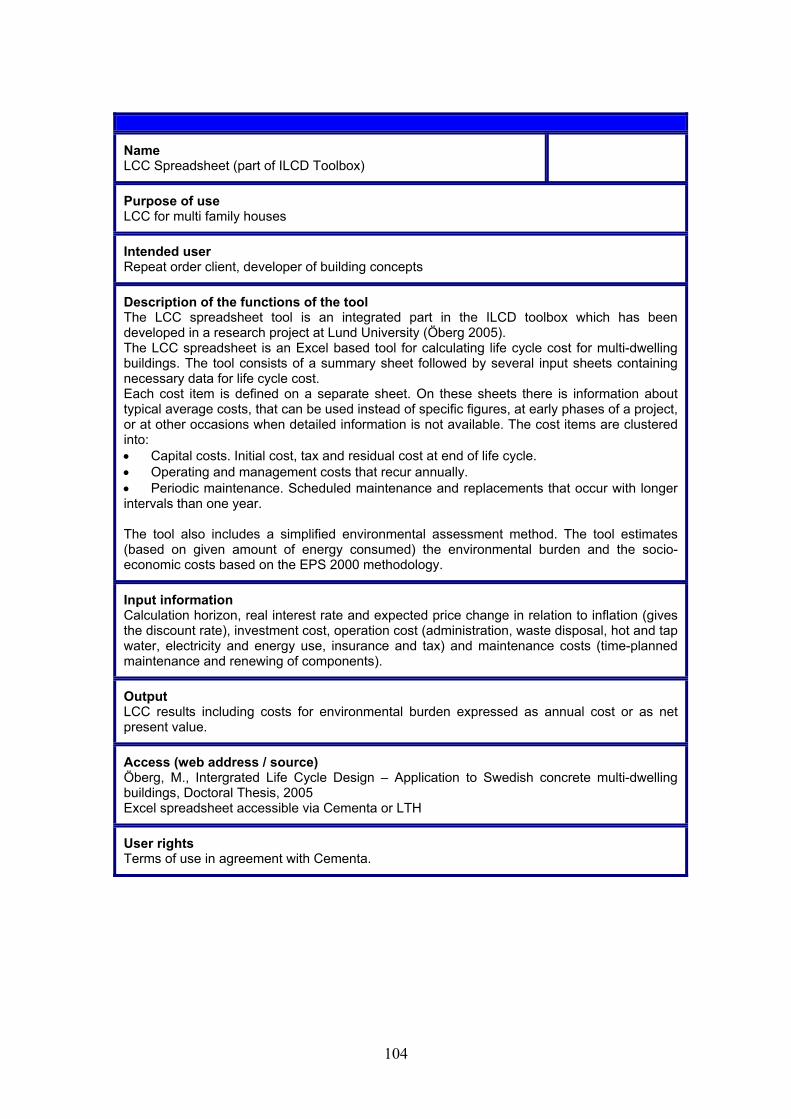
104
Name LCC Spreadsheet (part of ILCD Toolbox)
Purpose of use LCC for multi family houses
Intended user Repeat order client, developer of building concepts
Description of the functions of the tool The LCC spreadsheet tool is an integrated part in the ILCD toolbox which has been developed in a research project at Lund University (Öberg 2005). The LCC spreadsheet is an Excel based tool for calculating life cycle cost for multi-dwelling buildings. The tool consists of a summary sheet followed by several input sheets containing necessary data for life cycle cost. Each cost item is defined on a separate sheet. On these sheets there is information about typical average costs, that can be used instead of specific figures, at early phases of a project, or at other occasions when detailed information is not available. The cost items are clustered into: • Capital costs. Initial cost, tax and residual cost at end of life cycle. • Operating and management costs that recur annually. • Periodic maintenance. Scheduled maintenance and replacements that occur with longer intervals than one year. The tool also includes a simplified environmental assessment method. The tool estimates (based on given amount of energy consumed) the environmental burden and the socio-economic costs based on the EPS 2000 methodology.
Input information Calculation horizon, real interest rate and expected price change in relation to inflation (gives the discount rate), investment cost, operation cost (administration, waste disposal, hot and tap water, electricity and energy use, insurance and tax) and maintenance costs (time-planned maintenance and renewing of components).
Output LCC results including costs for environmental burden expressed as annual cost or as net present value.
Access (web address / source) Öberg, M., Intergrated Life Cycle Design � Application to Swedish concrete multi-dwelling buildings, Doctoral Thesis, 2005 Excel spreadsheet accessible via Cementa or LTH
User rights Terms of use in agreement with Cementa.
105
Name LifePlan
Purpose of use LifePlan is a web based tool and a concept for collection of environmental and service life information and formulation of a database for a building. LifePlan database is web browser based. Service life information is defined with using XML description language. The LifePlan database enables the user to browse and search information of different products.
Intended user Compiler of the product information for a building or building concept. A general or a building or building concept specific service life database can be collected with help of LifePlan. Intended process includes the following steps: 1) owner provides the access to LifePlan tool for manufacturers, 2) each manufacturer provides the service life information through web with using the LifePlan formats, 3) the XML-based data is organised as a building specific care and maintenance database by the owner.
Description of the functions of the tool The LifePlan concept was originally planned aiming at the creation of a database which would finally include the service life information about hundreds of products available for use in service life design and formulation of maintenance manuals. However, in one-actor-centred process like in an owner-centred building process, the system does not necessarily have to be an existing data base, but an existing facility. The process can operate in such a way that the owner requires all the suppliers of the project to include service life information into the database with help of which the compiler of the maintenance information collects and arranges the building information to form building systems specifically organised and scheduled product information for care and maintenance.
Input information Service life information includes the following aspects: identification, description of the product, predicted service life and required boundary conditions in terms of workmanship, outdoor conditions, care and maintenance. The same concept can be applied for the collection of all kinds of product information. ICTWLORB extended the LifePlan in such a way that also environmental profiles of products can be collected with help of the tool.
Output Output is a structured XML-based database of product information
Access (web address / source) http://ce.vtt.fi/lifeplan_iw/
User rights Public; Available through VTT
106
Name VIP+ (software for calculation of energy consumption)
Purpose of use The software calculates energy consumptions for a building with known or measurable energy flows.
Intended user Structural engineers and HVAC engineers
Description of the functions of the tool VIP+ is specialised on calculation of energy use for heating and cooling. It is not made for use in dimensioning of heating or cooling systems. VIP+ uses a one-zone model but there are possibilities to link multiple zones and calculate a dynamic energy exchange between several zones. The calculation is done hourly during a year. The calculation model include all important energy flows in a building for example solar radiation, heat accumulation, ventilation and air flow, heat exchangers, building and window orientation, heat pump, sun panels etc. Solar radiation is given from a climate file. The program calculates angles and direction toward windows and other building surfaces. Maximum solar radiation in clear weather is a known factor and the difference between this and the climate file determine the level of direct and diffuse radiation. Heat accumulation and U-values are calculated by the program based on user-defined values of necessary material properties. VIP+ is made to describe the building as real as possible and uses mathematical models to almost every calculation instead of reactor- or correction factors. This gives the model a high accuracy when the calculation is moved from early design to completed product. VIP+ considers the effect of air leakage and ventilation systems by hourly calculations of inside air pressure as a result of total air flow balance for infiltration and ventilation. VIP+ is working with climate data from the Swiss company Meteotest AG who delivers climate data from climate stations worldwide. In the Swedish version there are 20 Swedish cities included. Climate data could be adjusted to local conditions.
Input information Material and components specific information (coefficient of thermal conductivity, density and heat capacity). The user inserts data manually or picks materials with predefined values from the program�s database. The materials are combined together into building parts such as walls, slabs, roof etc. Required information for building parts are areas, orientation, height placement, infiltration factor, heat capacity and thermal insulation. The user could also pick predefined building parts from a database. In addition information about internal free gains and operation strategies and technical performance of heating and ventilation systems are also required.
Output Energy balance is calculated for three different cases: 1) Reference building with reference operation condition, 2) Reference building with actual operation condition, 3) Actual building with actual operational condition. Detailed result is shown for each calculation. Calculation result could be displayed summarised over a whole year or as hourly values. The result could also be given as costs and environmental impact. Schedules for energy costs and emission can be entered.
Access (web address / source) www.strusoft.com www.sundahusradgivning.se
User rights License required
107
References
Borefur, M. 2006. Utvärdering av byggsektorns miljöbedömningssystem BASTA: med avseende på utvalda installationsprodukter. Diploma Work. Göteborg: Chalmers University of Technology.
EU. 1988. Directive on construction products. Directive 89/106/EEC of the European Parliament. Brussels: European Union.
Hedenblad, G. & Arfvidsson, J. 2001. A material model to calculate the drying of concrete. Proc. CIPW40 Meeting, New Zealand.
Huovila, P. 2005. Decision support toolkit. PeBBu Generic Task 3. Final report no 23.
Kronudd, L. 2007. Beräkning av livscykelkostnader (LCC) i tidiga skeden av konceptbyggande. Diploma work. Div. Building Materials. Lund: Lund Technical Institute.
Kosonen, R. & Shemeikka, J. 1997. The use of a simple simulation tool for energy analysis. IBPSA Proc. September 8�10, 1997, Prague, Czech Republic.
Kähkönen, K. 1995. Preplanner: project initiation technology and tools.
Kähkönen, K. 1996. TEMPER-project risk management system.
Lessing, J. 2006. Industrialised House Building. Licentiate thesis. Div. of Design Methodology. Lund: Lund Institute of Technology.
Mjörnell, K. et al. 2007. A Method for Moisture Safety in the Building Process, to be published.
Nordic Ecolabelling. 2005. Swan labelling of small houses. Vers. 1.4. Stockholm, Sweden.
Sarja, A., Fukushima, T., Kuemmel, J., Mueller, C., Alexander, S., Oedeen, K. & Lepoivre, J.-P. 1999. Environmental design methods in materials and structural engineering � progress Report of RILEM TC 172-EDM/CIB TG 22. Materials and Structures, Vol. 32, No. 224, pp. 699�707.
Sikander, E. 2005. Byggherrens arbete för fuktsäker byggnad � Krav, uppföljning, hjälpmedel och erfarenheter. SP Rapport 2005:13.

108
Sikander, E. & Mjörnell, K. N. 2007. Moisture Management in the Building Process � Experience from Four Projects. Borås, Sweden: SP Swedish National Testing and Research Institute.
Trinius, W. & Sjöström, C. 2005. Service life planning and performance requirements. Building Research & Information, Vol. 33, pp. 173�181.
Öberg, M. 2005. Integrated life-cycle design in residential buildings. PhD thesis. Div of Building Materials. Lund: Lund Institute of Technology.

109
Chapter 6 Contents
6. Case studies..............................................................................................................111 6.1 Introduction ....................................................................................................111 6.2 EcoProP/ModernaHus ....................................................................................111
6.2.1 EcoProP tool.......................................................................................111 6.2.2 Skanska�s ModernaHus concept ........................................................113 6.2.3 Requirements management in Skanska�s Almby housing
project in Örebro ................................................................................115 6.2.4 Experiences and feedback ..................................................................115 6.2.5 Conclusions ........................................................................................117
6.3 Service-life tools for concrete structures........................................................120 6.3.1 Background ........................................................................................120 6.3.2 Traditional concrete durability design ...............................................120 6.3.3 ENNUS-Concrete...............................................................................122
6.3.3.1 Background .........................................................................122 6.3.3.2 Service-life with respect to frost in exposure classes
XF1 and XF3 (without salts)...............................................124 6.3.3.3 Service-life with respect to corrosion in exposure
classes XC1 to XC4 (without salts) ....................................128 6.3.3.4 Service-life with respect to frost in exposure classes
XF2 and XF4 (with de-icing salts)......................................130 6.3.3.5 Conclusion ..........................................................................130
6.3.4 SBF-SLD-tool ....................................................................................131 6.3.4.1 Background .........................................................................131 6.3.4.2 Principles of performance based service-life design...........132 6.3.4.3 Frost ....................................................................................134 6.3.4.4 Frost and salt .......................................................................135 6.3.4.5 Carbonation-initiated reinforcement corrosion...................136 6.3.4.6 Chloride-initiated reinforcement corrosion.........................137 6.3.4.7 Consequences of corrosion .................................................138 6.3.4.8 Environmental actions on concrete structures ....................140 6.3.4.9 Methods for determining new material and
environmental parameters ...................................................140 6.3.4.10 Conclusions.........................................................................140
6.3.5 References ..........................................................................................140 6.4 LifePlan/Ecometer..........................................................................................142
6.4.1 Introduction of LifePlan and Ecometer..............................................142 6.4.1.1 Ecometer .............................................................................142 6.4.1.2 LifePlan and LCA ...............................................................142
6.4.2 Purpose of the case study ...................................................................143

110
6.4.3 Case study ..........................................................................................143 6.5 LifePlan/ModernaHus ....................................................................................144
6.5.1 Introduction of LifePlan.....................................................................144 6.5.2 Purpose of the case study ...................................................................146 6.5.3 Case study ..........................................................................................147 6.5.4 Data supply for LifePlan database, guide ..........................................149 6.5.5 Discussions/problems.........................................................................154
References................................................................................................................155 6.6 Lifecycle costs for industrialised concept buildings � experiences
of applying LCC spreadsheet to ModernaHus ...............................................155 6.6.1 Introduction ........................................................................................155 6.6.2 Objectives...........................................................................................155 6.6.3 Introduction to LCC and ILCD..........................................................156 6.6.4 Description of tested tools..................................................................160
6.6.4.1 LCC Spreadsheet.................................................................160 6.6.4.2 Life cycle cost data .............................................................162 6.6.4.3 Calculation horizon .............................................................162 6.6.4.4 End of the life cycle ............................................................163 6.6.4.5 Verification of the LCC tool ...............................................164 6.6.4.6 Full LCA method ................................................................165 6.6.4.7 VIP+ (energy balance calculation)......................................166
6.6.5 Description of ModernaHus...............................................................166 6.6.6 Results from the case study................................................................168
6.6.6.1 Theory is put into practice ..................................................168 6.6.6.2 LCC Spreadsheet.................................................................169 6.6.6.3 Energy calculation using VIP+ ...........................................170 6.6.6.4 Basis for calculations ..........................................................171 6.6.6.5 Sensitivity analysis..............................................................172 6.6.6.6 Calculation results...............................................................173
6.6.7 Analyse and conclusions ....................................................................176 6.6.7.1 LCC methodology applied to an industrialised building process .177
References ......................................................................................................179 6.7 Risks of non-performance in industrialized construction...............................181
6.7.1 Abstract ..............................................................................................181 6.7.2 Introduction ........................................................................................181 6.7.3 A hypothesis on variations in expected performance in principle .....182 6.7.4 Quantification of uncertainties � some examples ..............................185 6.7.5 Uncertainties included in life-cycle cost calculations........................190 6.7.6 Discussion and conclusions................................................................193 6.7.7 Acknowledgements ............................................................................193 References ......................................................................................................193

111
6. Case studies
6.1 Introduction
Several case studies were carried out by groups of participants in the project. This chapter presents the results of the case studies. The case studies concern the usability of LC tools in building projects with particular reference to industrialised building processes and residential buildings.
6.2 EcoProP/ModernaHus
by Katarina Suber (Skanska Sverige AB), Pekka Huovila and Janne Porkka (VTT Technical Research Centre of Finland)
6.2.1 EcoProP tool
EcoProP is a software tool that can be used to
− create a performance based design brief (to set objectives how the building should perform in use)
− show requirement profiles (using pre-defined classes from 1 to 5)
− evaluate LCA impacts between alternative requirement options (five indicators relating with the use phase of the building, originating from a database and expert knowledge, where real environmental [e.g. energy] profiles of can be applied if available)
− provide rough LCC estimates based on requirement levels to support decision making in early phases of target setting (see Figure 6.1).

112
Figure 6.1. Main functionalities of EcoProP tool for requirements management.
EcoProP is mainly used by (or together with) developers (owners, project management consultants) in collaboration with the design team before technical solutions for construction are chosen. The objective is to capture and maintain customer requirements in the process in order to achieve solutions that meet customer needs and add value to owners and end users. Customer requirements are published as a report where performance requirements can be used in the project (e.g. as an appendix to the design brief).
The screenshot below (Figure 6.2) demonstrates the user interface of EcoProP tool; tree structure on left is used for the performance classification and right part of the layout contains detailed requirement characteristics (target values) related with pre-defined classes from the data base, validation methods and reference information. Users may also define additional information as comments (Figure 6.3).
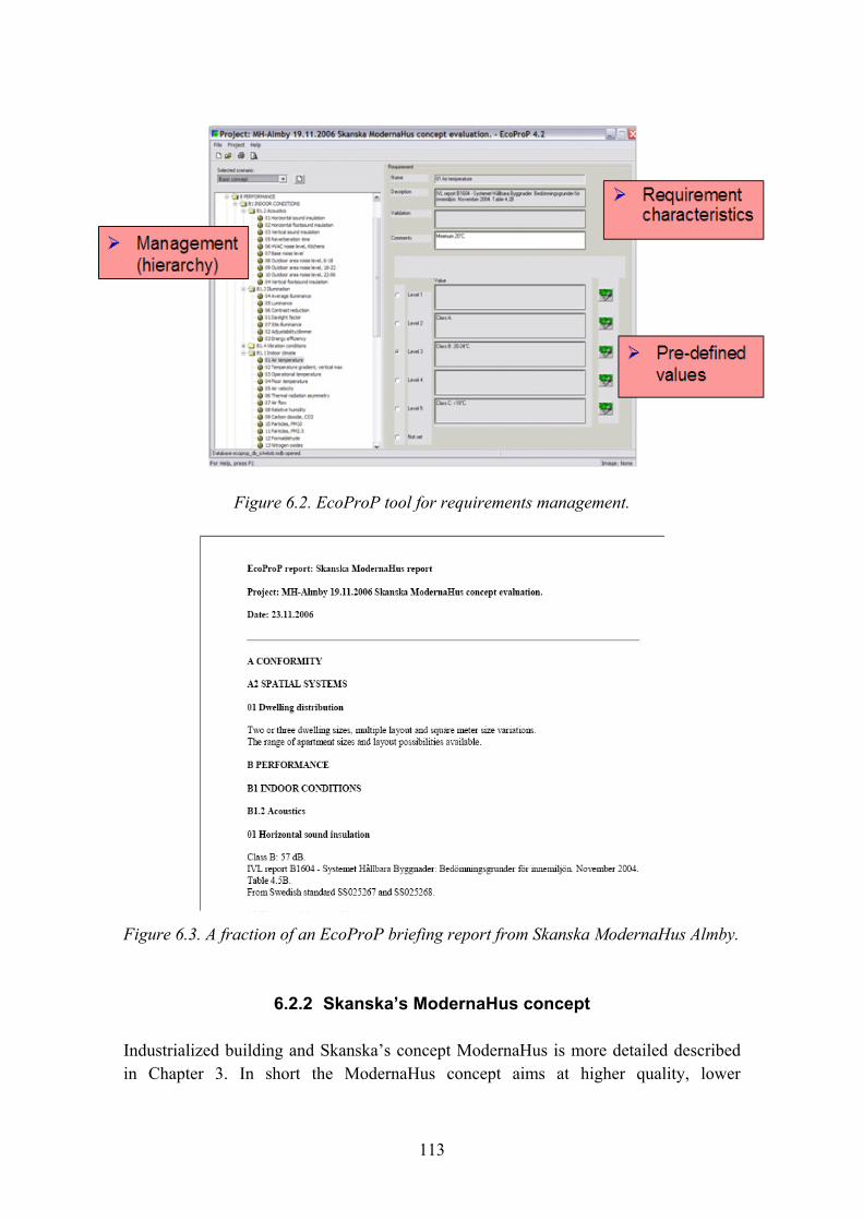
113
Figure 6.2. EcoProP tool for requirements management.
Figure 6.3. A fraction of an EcoProP briefing report from Skanska ModernaHus Almby.
6.2.2 Skanska�s ModernaHus concept
Industrialized building and Skanska�s concept ModernaHus is more detailed described in Chapter 3. In short the ModernaHus concept aims at higher quality, lower
114
construction costs and lower energy consumption during usage. The industrialized construction process and technical solutions halves the construction time and at the same time the production cost and energy consumption is decreased with 30% compared to traditional cast-in-place constructions.2
Skanska has developed ModernaHus which is a platform for multi dwelling buildings, both point and slab block from 3 to 8 stories. The idea of ModernaHus is to use standardized components that can be varied to different types of buildings. This system can be compared to the method that the car industry is using with the same platform for different models. In this way the houses built on the same component can look very different. When using standardized components, the purchase of material can be made in larger a volume which lowers the cost without compromising the variation or the quality.
An important part of the industrialized construction process is prefabrication. By producing volume modules in a plant, it will create time- and quality benefits. On the assembly site the modules are then mounted together. The decisive parameters within the industrialized ModernaHus concept are for example the stair cases and balconies that have standardized measures as well as the wet rooms and the roof that are prefabricated volume modules. The design of the apartments in ModernaHus is flexible. This means that the platform can be used in different types of apartments such as student apartments (which is corresponding to a minim level), senior apartments (with higher demands on for example accessibility). The platform can also be configured so that the balconies are available with a wheelchair.
Using the standardized solutions makes it is possible to control the production process and the quality of the end product. When applying the ModernaHus concept it is possible to control cost and quality in a better way that in traditional housing practice. The higher concept level is more preferable and ModernaHus can be used when the concept level is not less than 75% of the purchasing plan in the concept template. In addition, a set of strategic components must not be changed. Whenever special adaptations are made they are developed in a traditional way (see Chapter 3).
The energy consumption is a large part of the total life cycle cost for a building. The heating of dwellings and premises stands for about 39% of the total energy use in the community. This is why the buildings energy qualities is getting more and more important for both real estate owners, end users and last but not least the environment.
2 www.skanska.se/modernahus.
115
ModernaHus has an energy consumption that is 30% lower than average new traditional cast-in-place multi family dwellings.3
6.2.3 Requirements management in Skanska�s Almby housing project in Örebro
The test was conducted at Skanska�s head office in Solna, Stockholm Thu 16 Nov 2006. Skanska Sverige AB, Skanska Teknik, was represented by Leif Johansson, Johanna Nordström, Carl Jonsson, Erik Berggren and Katarina Suber. VTT was represented by Janne Porkka and Pekka Huovila.
Since we are still lacking European standards defining the performance characteristics of a whole building VTT ProP® was selected as the framework. EcoProP tool includes an extensive Finnish database supporting that structure. It is partly completed by supplementary data from some international projects. For this test case Swedish Indoor criteria (IVL Swedish Environmental Research Institute Report4) and some other project related local reference data were pre-filled in and thus available during the trial.
The test was conducted basically in two 2 to 3 hour sessions. The morning one captured and formalized (in successful cases) the requirement levels and contents (additional comments) using EcoProP and the afternoon session addressed more to discussion around the ModernaHus concept and to obtain feedback from the exercise.
The test day provided a lot of new information about the ModernaHus concept, and even more confidential information was obtained afterwards enabling the researchers to form a good overall picture of the system. The design brief that was created using EcoProP is shown in the Annex. It was started together with the Skanska experts in Solna and completed at VTT Espoo afterwards, enriched with data that was not accessed before or during the trial.
6.2.4 Experiences and feedback
The following experiences were shared during the test:
− Interesting discussion on many important aspects was stimulated during the requirement setting leading to thinking process towards further improvements.
3 www.skanska.se/modernahus. 4 Systemet Hållbara Byggnader: Bedömningsgrunder för innemiljön [Nov 2004].

116
− The requirement levels in performance categories that were chosen for Almby seldom exceeded the minimum (societal) requirements, however.
− The numeric values of discussed requirement categories (mainly indoor climate) didn�t seem to be familiar in everyday practice (the experts couldn�t easily tell their target values, origin, justification or consequences).
− The �customer oriented� approach was not fully supported by the (more product or production oriented) ModernaHus concept, which is based on an extensive pre-defined product (component) library, where designers select Skanska�s given technical solutions (that may still lead to improved customer satisfaction at the end even though the process does not include user segmentation or customer involvement).
− Discussion about a unified, reliable LCC calculation and management was raised as part of the decision making procedure.
− Also Energy Plus concept was discussed (�30% in use for clients interested in low cycle costs) even though that was not selected for Almby.
− Environmental rating was discussed and Swan label for buildings was given as an example.
− Since the designers didn�t participate in the session the impacts of the use of EcoProP tool in Almby project will presumably remain modest.
The following feedback was obtained afterwards from four Skanska�s experts that took part of the requirements management session.
1. Which were the things I found positive during the tool test (please, be as specific as possible) − the overall idea of defining the criteria before designing the building
− the simplicity that appears when we started the testing
− the possibility to test and compare different cases
− the graphic overview in the reports.
2. Features I disliked (approach, interface, database content, reporting qualities etc.) − at the first look, the tool looks very complex and time consuming to perform the test
3. Where could I use in real life requirements management (or LCA, service life) software like EcoProP − in my work I would say almost never but Skanska as a company could have a lot
to gain by using this
− could it be modified in, for example development and research projects

117
− a good tool for LCC estimates in the early phases of the project would be very useful benchmarking (LCA, LCC) ModernaHus with traditional house building would be very interesting
− another interesting part would be to see how Energy+ affects to LCA and LCC
− I would also like to see the now-values and return on investment calculations of Energy+
4. What kind of IT tool am I really lacking in my everyday practice − a tool for feedback, not only a tool to handle deviations and mistakes, but for
actual feedback with concrete suggestions (may be filled out by the �owner�) how to work in the future
5. The following ideas are recommended to be considered when developing IT based requirements management tools (such as EcoProP) − make the interface look as simple as possible; you don�t want to scare the user �
they are supposed to feel like this will help them and not give them more work
6.2.5 Conclusions
The industry led European Construction Technology Platform (ECTP) has stated its vision
− to add value to present and future stakeholders
− to deliver sustainable outcomes
− to help the transformation into a knowledge and service based industry, characterised by sustained innovation and excellence.
This tool experimentation raised the question of incentives and barriers related with improved user orientation and sustainability to meet these objectives. Number of systematic tools (e.g. those compiled in ICTWLORB) is and has been available for years, but they are not in active use. Are the barriers related with the technology, human interface, resistance to change or are there other good reasons why meeting the ECTP objectives seems to be still far away from current good practice.
An explanation to the tools not being used in large companies like Skanska could be that tools and aid have been developed within the company for many years. In many cases today the employees have a good IT-knowledge and no matter if a new tool has a user-friendly interface it might just feel like an extra work task to perform adding to the normal work load and the implementation can be difficult.
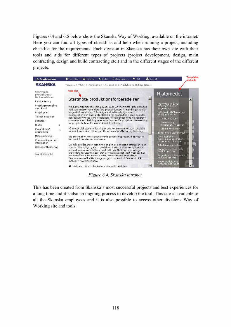
118
Figures 6.4 and 6.5 below show the Skanska Way of Working, available on the intranet. Here you can find all types of checklists and help when running a project, including checklist for the requirements. Each division in Skanska has their own site with their tools and aids for different types of projects (project development, design, main contracting, design and build contracting etc.) and in the different stages of the different projects.
Templatesand aids
Help text
Templatesand aids
Help text
Figure 6.4. Skanska intranet.
This has been created from Skanska�s most successful projects and best experiences for a long time and it�s also an ongoing process to develop the tool. This site is available to all the Skanska employees and it is also possible to access other divisions Way of Working site and tools.

119
Figure 6.5. Skanska intranet.
The standardized Way of Working provides continuity within the company that makes it easier to move labour from place to place and between divisions etc. and also to read and understand each others documents. Since this is only available on the intranet, it eliminates the handling of versions.
In other industries many frontrunner companies (Nokia, IBM etc.) have chosen the approach of involving end-users as part of their product (or service) development processes to achieve gains in lead time and to meet better user requirements � in other words: to succeed. This doesn�t seem to be the case in building construction.
To exploit future opportunities it is left for further consideration if a systematic requirements management tool, such as EcoProP could add value
− when developing new housing concepts (for urban singles, greenies, ICT freaks, elderly/wealthy, young indebted / immigrants or other customers)
− for demanding clientele with individually (or market segment) defined �personalized� requirements to improve customer satisfaction, loyalty, branding (and profit margins)
− if market differentiation could be seen as a business driver
− in cases where business success factors relate directly with product properties (performance in use) rather than other issues
− if housing sales prices (and value) correlated with the performance (quality) of the product (building + services).
120
Skanska�s ModernaHus concept gave a good impression on progressive and efficient industrialized building. Referring to the discussion during the day one might wonder how construction market could be created for Audi and Mercedes, in addition to Volkswagen that can now be delivered for all.
6.3 Service-life tools for concrete structures
Lars-Olof Nilsson, Sirje Vares and Erkki Vesikari
6.3.1 Background
The service life of materials, components, structures and systems is essential to know for several reasons in ILCD. The service-life is a significant input to mainly LCC and LCA. For most materials and components the service-life is found from experience and provided by the suppliers and included in ICT-tools like LifePlan or by user organisations like SABO and included in data-bases in LCC-tools (Öberg 2005).
For concrete structures, however, the variety of material qualities and exposure conditions is huge and calculation tools are needed. Here a few tools are presented.
6.3.2 Traditional concrete durability design
Today, durability design for most concrete structures is done according to EN-206-1 (2000). First, the environmental actions on the particular structural part are identified and an appropriate �exposure class� in EN-2006 is selected. An example for a residential building is given in Figure 6.6.

121
X0
X0
X0/XC1
XC2
XC3,4, XF1or XD1, XF2
XC3, XF1
XC4, XF3XD1?
XC3,4, XF1
Figure 6.6. Examples of exposure classes according to EN-206-1 for some parts in a residential building. Picture drawn from BY-50.
The next step is to select the concrete composition and concrete cover for the reinforcement from tables where the exposure class and the required service-life are the main input parameters. Such a table, in principle, is shown in Figure 6.7.
XF1-4
XS1-3(Sea water Cl-corr)
XD1-3(De-icing Cl-corr)
XC1-4 (CO2-corr)
Concrete composition (cement type, w0/C, cement content, air content)CuringConcrete cover for reinforcement
X0 (no risk)
1201005020ExposureClass
Required service life (years)
XF1-4
XS1-3(Sea water Cl-corr)
XD1-3(De-icing Cl-corr)
XC1-4 (CO2-corr)
Concrete composition (cement type, w0/C, cement content, air content)CuringConcrete cover for reinforcement
X0 (no risk)
1201005020ExposureClass
Required service life (years)
Figure 6.7. A table, in principle, for selection of concrete composition from the exposure class and the required service-life.
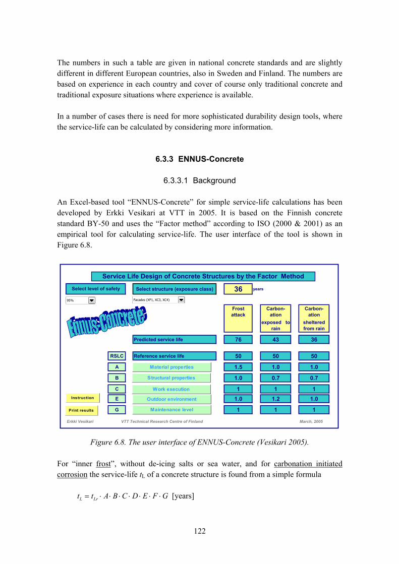
122
The numbers in such a table are given in national concrete standards and are slightly different in different European countries, also in Sweden and Finland. The numbers are based on experience in each country and cover of course only traditional concrete and traditional exposure situations where experience is available.
In a number of cases there is need for more sophisticated durability design tools, where the service-life can be calculated by considering more information.
6.3.3 ENNUS-Concrete
6.3.3.1 Background
An Excel-based tool �ENNUS-Concrete� for simple service-life calculations has been developed by Erkki Vesikari at VTT in 2005. It is based on the Finnish concrete standard BY-50 and uses the �Factor method� according to ISO (2000 & 2001) as an empirical tool for calculating service-life. The user interface of the tool is shown in Figure 6.8.
Select structure (exposure class) 36 years
Frost attack
Carbon-ation
Carbon-ation
exposed to rain
sheltered from rain
Predicted service life 76 43 36
RSLC Reference service life 50 50 50
A 1.5 1.0 1.0
B 1.0 0.7 0.7
C 1 1 1E 1.0 1.2 1.0
G 1 1 1
Erkki Vesikari March, 2005VTT Technical Research Centre of Finland
Select level of safety
Service Life Design of Concrete Structures by the Factor Method
95%
Material properties
Structural properties
Work execution
Outdoor environment
Maintenance levelPrint results
Instruction
Facades (XF1, XC3, XC4)
Figure 6.8. The user interface of ENNUS-Concrete (Vesikari 2005).
For �inner frost�, without de-icing salts or sea water, and for carbonation initiated corrosion the service-life tL of a concrete structure is found from a simple formula
GFEDCBAtt LrL ⋅⋅⋅⋅⋅⋅⋅= [years]
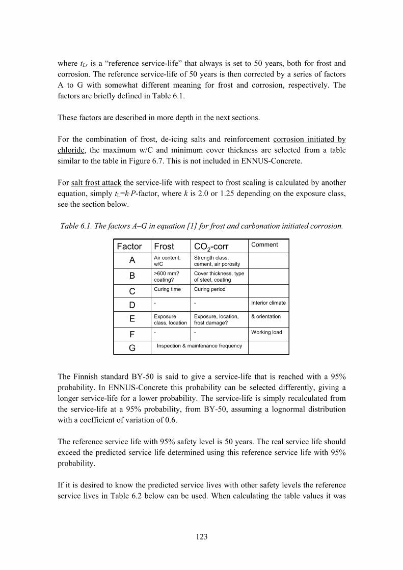
123
where tLr is a �reference service-life� that always is set to 50 years, both for frost and corrosion. The reference service-life of 50 years is then corrected by a series of factors A to G with somewhat different meaning for frost and corrosion, respectively. The factors are briefly defined in Table 6.1.
These factors are described in more depth in the next sections.
For the combination of frost, de-icing salts and reinforcement corrosion initiated by chloride, the maximum w/C and minimum cover thickness are selected from a table similar to the table in Figure 6.7. This is not included in ENNUS-Concrete.
For salt frost attack the service-life with respect to frost scaling is calculated by another equation, simply tL=k⋅P-factor, where k is 2.0 or 1.25 depending on the exposure class, see the section below.
Table 6.1. The factors A�G in equation [1] for frost and carbonation initiated corrosion.
Inspection & maintenance frequencyG
Working load--F
& orientationExposure, location, frost damage?
Exposureclass, locationE
Interior climate--D
Curing periodCuring timeC
Cover thickness, typeof steel, coating
>600 mm? coating?B
Strength class, cement, air porosity
Air content, w/CA
CommentCO2-corrFrostFactor
The Finnish standard BY-50 is said to give a service-life that is reached with a 95% probability. In ENNUS-Concrete this probability can be selected differently, giving a longer service-life for a lower probability. The service-life is simply recalculated from the service-life at a 95% probability, from BY-50, assuming a lognormal distribution with a coefficient of variation of 0.6.
The reference service life with 95% safety level is 50 years. The real service life should exceed the predicted service life determined using this reference service life with 95% probability.
If it is desired to know the predicted service lives with other safety levels the reference service lives in Table 6.2 below can be used. When calculating the table values it was

124
assumed that the distribution of the service life is log-normal and the coefficient of variation is 0.6 (probably a conservative guess).
Table 6.2. Reference service lives as a function of safety level.
Safety level Reference service life years
95% 90% 80% 50% Mean
50 61 78
124 145
6.3.3.2 Service-life with respect to frost in exposure classes XF1 and XF3 (without salts)
The calculation of the service-life with respect to �inner� frost, without frost-salt scaling, is done by equation [1] where the factors A to G are taken from tables in BY-50.
Factor A
The factor A, a �material factor�, depends mainly on the water-cement-ratio w/C and the air content. The maximum size of aggregate has a minor influence. There are two tables for factor A, one for facades and one for balconies, see Table 6.3.
Table 6.3. Factor A in exposure class XF1 (Facades). The shaded areas may only be used for cases of non-conformity.
1.572.123.314.004.004.004.007.07.58.0
Not accepted≥8.5≥9.0≥9.5
1.862.658.08.59.0
1.712.363.934.004.007.58.08.5
1.00-1.44
1.22-1.90
1.57-2.82
2.25-4.00
4.004.004.004.5-6.5
5.0-7.0
5.5-7.5
0.901.081.351.853.014.004.004.04.55.0
1.161.522.254.004.003.54.04.5
2.864.003.03.54.0
Not accepted≤2.5≤3.0≤3.5
0.700.650.600.550.500.450.400.350.3016128
Factor A for w/C (Facades)Air contentMax.stones, mm

125
Table 6.4. Factor A in exposure class XF3 (Balconies). The shaded areas may only be used for cases of non-conformity.
1.582.624.004.004.004.007.58.08.5
Not accepted≥9.0≥9.5≥10
1.998.59.09.5
1.773.164.004.008.08.59.0
1.412.214.004.004.004.007.07.58.0
0.72-1.26
0.90-1.88
1.23-3.85
2.00-4.00
4.004.004.0-7.0
4.5-7.5
5.0-8.0
0.630.771.011.503.084.003.54.04.5
3.03.54.0
Not accepted≤2.5≤3.0≤3.5
0.700.650.600.550.500.450.400.350.3016128
Factor A for w/C (Balconies)Air contentMax.stones, mm
The dependency on air content and w/c was defined according to the slab test results (the Borås slab test) with pure water. In that test method the specimens are exposed to frequencies of freezing and thawing when constantly exposed to water and the surface scaling it measured. Most probably the loss of compressive strength was also measured and a loss of 1/3 was defined as the limit state. No tests were made for different binders such as slag cement concrete, only Portland cement concrete.
The values of coefficient A for facades and balconies were based on the Borås slab test with pure water. Both the scaling (g/m2) and the reduction in the ultra sound penetration time (%) were measured. A fitted function of exponential form was searched from the results. The coefficients A were calculated with the following formulas.
Facades (XF1):
⎟⎟⎟⎟⎟⎟
⎠
⎞
⎜⎜⎜⎜⎜⎜
⎝
⎛
⎟⎟
⎠
⎞
⎜⎜
⎝
⎛⎟⎟⎠
⎞⎜⎜⎝
⎛
−⋅+−
=
141,0
451,0
)1(0,2377,130;1,0
33;4
aMax
MinAcw

126
Balconies (XF3):
⎟⎟⎟⎟⎟⎟
⎠
⎞
⎜⎜⎜⎜⎜⎜
⎝
⎛
⎟⎟
⎠
⎞
⎜⎜
⎝
⎛⎟⎟⎠
⎞⎜⎜⎝
⎛
−⋅+−
=
141,0
451,0
)1(0,2377,130;1,0
22;4
aMax
MinAcw
In the formulae w/c = effective water/cement ratio and a = air content, %.
The expression in the denominator tells the result in the slab test as the decrease of ultra sound penetration time (%) after 56 cycles. So the service life is assumed to be inversely proportional to the result in the slab test. The figure in indicator was fitted to yield a reasonable service life. The minimum reduction in ultra sound penetration time was considered 0.1%.
The maximum value for coefficient A was considered to be 4 because it would not be possible to predict service lives longer than 200 (= 4 * 50) years with this method.
As the air content affects the service life very sensitively the formulas for coefficient A were derived so that an amount of 1% is reduced from the air content of concrete. This provides extra safety for the service life design.
The tables say several things. The maximum service-life will be 200 years with respect to frost (A = 4.00) for the best concretes with a low w/C and high air contents. For w/C 0.40 and higher, with low air contents, the service-life will be shorter. This must mean that some frost damage is accepted for these cases, i.e. the concrete is not fully frost resistant. The tables also say that a concrete with w/C 0.50�0.55 or higher, or concrete with a low air content, can never be frost resistant in these applications. The difference between the two tables is that balconies require a somewhat lower w/C and a slightly higher air content to reach the same service-life.
Only one �acceptable� façade concrete will have a service-life shorter than 50 years, with w/C 0.65 and air content lower than 4�5%. Such a short service-life will follow for balconies if w/C is 0.55�0.60 and the air content is lower than 5�6%.
The quality of the air void system is not considered in BY-50. According to BY-50 there is no benefit of applying a frost test to assess the true material properties, for instance the critical degree of saturation or the degree of saturation due to the exposure situation.

127
Factors B�C & G
There are two factors B. The factor B1 depends on something called the �massivity� of the structure, which is the dimension of the structure. If the smallest dimension is larger than 0.6 m the service-life is calculated to be 30% longer. The reason for this factor is not clear. The factor B1 is empirical. Massive structures have proved to be more resistant than normal structures. The greater heat capacity may explain some of it. The factor B2 concerns the effect of coatings on the frost durability and is not further treated here.
The factor C depends on curing. If the curing is bad, the service-life is given a 30% lower value. This seems to be a very crude way to consider the effect of curing on frost resistance.
The factor G concerns the maintenance level. A frequency of inspection and maintenance of 1�2 years is expected and the factor G then equals 1.0. If the frequency is longer, the service-life is said to be 30% shorter!
Factors E
There are two factors E, for geographical location and orientation. The factor E1 concerns the direction, with a factor of E1=1.0 for structures facing south and southwest and E1=2.0 when facing north. In all other directions E1=1.1�1.7. This must mean that the factor E1 depends on the amount and frequency of driving rain, i.e. the actual degree of saturation. The factor E1 seems to be the same for vertical and horizontal surfaces which is strange. Horizontal surfaces exposed to rain should become more saturated than vertical surfaces and consequently a factor for the effect of exposure to rain should be smaller. This effect, however, may be included in the factor A. The direction of the structure (vertical/horizontal) is already considered in the A factor. So the A factor for balconies is smaller than that for facades.
The factor E2 concerns the geographical location, with structures in the centre and north part of the country, further than 50 km from the coast, achieving a service-life that is 10 and 20% longer, respectively. The geographical location should include both the effect of exposure to driving rain and to freezing temperatures and number of frost cycles. It seems strange that these effects are not larger than 10�20%.
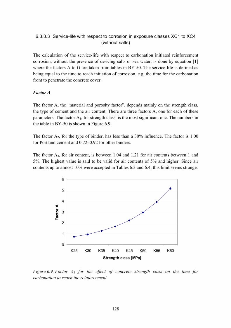
128
6.3.3.3 Service-life with respect to corrosion in exposure classes XC1 to XC4 (without salts)
The calculation of the service-life with respect to carbonation initiated reinforcement corrosion, without the presence of de-icing salts or sea water, is done by equation [1] where the factors A to G are taken from tables in BY-50. The service-life is defined as being equal to the time to reach initiation of corrosion, e.g. the time for the carbonation front to penetrate the concrete cover.
Factor A
The factor A, the �material and porosity factor�, depends mainly on the strength class, the type of cement and the air content. There are three factors A, one for each of these parameters. The factor A1, for strength class, is the most significant one. The numbers in the table in BY-50 is shown in Figure 6.9.
The factor A2, for the type of binder, has less than a 30% influence. The factor is 1.00 for Portland cement and 0.72�0.92 for other binders.
The factor A3, for air content, is between 1.04 and 1.21 for air contents between 1 and 5%. The highest value is said to be valid for air contents of 5% and higher. Since air contents up to almost 10% were accepted in Tables 6.3 and 6.4, this limit seems strange.
0
1
2
3
4
5
6
K25 K30 K35 K40 K45 K50 K55 K60
Strength class [MPa]
Fact
or A
1
Figure 6.9. Factor A1 for the effect of concrete strength class on the time for carbonation to reach the reinforcement.

129
The effect of the type and amount of binder and the concrete composition should be the effect on the diffusion coefficient for carbon dioxide on one hand and the amount of carbonatable material on the other. For an individual binder there is of course a strong relationship between strength and water-binder-ratio and impermeability to carbon dioxide and a strong relationship between water-cement-ratio and cement content. The background data for the numbers are unknown. There are reasons to believe that the effect of w/C or strength class is not unique for all types of binders and the effect of air content should be different in a low-porosity concrete and a high-porosity concrete.
Factors B, C and G
The factors B are considering the geometric effect of resistance to carbonation. One factor is related to the thickness of the cover and the other to the resistance of a coating at the concrete surface. The factor B2 is related to the �service-life� of the coating and its resistance to diffusion of CO2, tested by EN 13295.
The factor B1 is simply related to the cover thickness squared. The numbers in the table in BY-50 can be calculated from:
2
,1 ⎟⎟
⎠
⎞⎜⎜⎝
⎛=
REFc
c
xxB
where the �reference thickness� xc,REF is 25 and 30 mm for normal reinforcement and pre-stressing reinforcement respectively. The different numbers for normal reinforcement and pre-stressing steel implies that the service-life for e.g. hollow-core slabs is shorter than for slabs with normal reinforcement. This must be questioned since hollow-core slabs may have longer service-lives for a number of reasons that are not considered, such as smaller variations in concrete quality and cover thickness due to better workmanship and production control.
The factor C, for the effect of curing, is simply put to 0.7 for bad curing, which is very rough. The factor G, for inspection and maintenance frequency, is put to 0.85 for a frequency less than once every 1�2 years. This is of course nonsense, when the service-life is defined as the time for initiation of corrosion. There is nothing visible to inspect during the service-life!
Factors E
The factor E, for the effect of environmental actions, consists of four separate factors E1 to
E4. All of them equal 1.0 for a structure protected from rain, or soil moisture. For underground structures E1 is put to 1.4 and for structural parts exposed to rain E1 equals 4.0.
130
In addition to E1=4.0, for structural parts sometimes exposed to rain, E2 equals 0.8�1.4 depending on he direction compared to southwest, with south having E2=0.80, and E3=1.0�1.3 depending on the geographical location, with drier conditions and larger E3 in the centre and north of the country.
A factor E4 considers the effect of frost scaling on carbonation! Frost scaling reduces the cover thickness and consequently the time required to carbonate the concrete cover. The factor E4 is simply put to ¼ of factor A in Tables 6.3 and 6.4. This means that E4 equals 1.0 where there is no frost scaling at all and the service-life with respect to carbonation-induced reinforcement corrosion is significantly reduced because of �acceptable� frost scaling. That kind of frost damage should not be accepted at all during the service-life!
6.3.3.4 Service-life with respect to frost in exposure classes XF2 and XF4 (with de-icing salts)
The calculation of the service-life with respect to frost scaling due freezing in the presence of de-icing salts is done by a simple equation
PktL ⋅=
where k equals 2.00 for exposure class XF2 (vertical surfaces, moderate saturated) and 1.25 for exposure class XF4 (horizontal, saturated surfaces). The factor P is given by a strange equation, which for Portland cement concrete is
( )( )( )
1
21010
log17.085.0462.1
0
−⎟⎠⎞
⎜⎝⎛ −⋅+⋅
⋅+⋅=
aC
awt
P curing [years]
where C is the cement content [kg/m3], w0 is the mixing water [kg/m3], a is the air content (%) and tcuring is the curing period [days].
6.3.3.5 Conclusion
The service-life calculation tool is extremely simple to use and it seems to reflect the Finnish concrete code BY-50 in an excellent way. The code BY-50, however, seems strange in many parts and the principle of the factor method can be questioned, with a large number of factors being treated as independent factors.

131
6.3.4 SBF-SLD-tool
6.3.4.1 Background
CEB (1997) concluded that �a modern durability design procedure must meet the following conditions:
− durability must be treated in an explicit way, the behaviour and the maintenance of the structure during its service life must be clear
− functional requirements and performances of the structure are the basis
− a format similar to the load design procedure for structures
− extendable to non-structural aspects�.
Later, the EU-project DuraCrete developed a complete framework for such a durability design procedure, set up a series of models for degradation and environmental actions and quantified the parameters statistically. The Annex J of EN-206-1 gives a lot of examples where a performance based durability design could be favourable:
− required service-life is far from 50 years − a special structure − a lower probability of failure is required − a special environment or a very well known or defined environment − a high lever of workmanship − a strategy for maintenance − several similar structures − new or different concrete constituents − standard specifications are not fulfilled.
The Swedish Concrete Association formed a group to give guidelines on how to use the DuraCrete concept for Swedish conditions. A report is published in 2007. In the present project these guidelines have been used to develop a first version of an Excel-based tool for service-life calculations. The 2nd version of the user interface of that tool is shown in Figure 6.10.
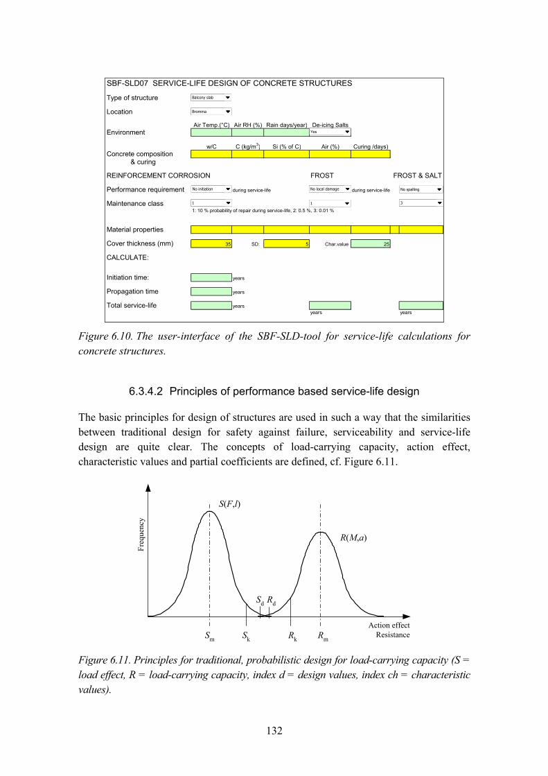
132
SBF-SLD07 SERVICE-LIFE DESIGN OF CONCRETE STRUCTURES
Type of structure
Location
Air Temp.(°C) Air RH (%) Rain days/year) De-icing SaltsEnvironment
w/C C (kg/m3) Si (% of C) Air (%) Curing /days)Concrete composition
& curing
REINFORCEMENT CORROSION FROST FROST & SALT
Performance requirement during service-life during service-life
Maintenance class1: 10 % probability of repair during service-life, 2: 0.5 %, 3: 0.01 %
Material properties
Cover thickness (mm) 35 SD: 5 Char.value 25
CALCULATE:
Initiation time: years
Propagation time years
Total service-life yearsyears years
Balcony slab
Bromma
No initiation No local damage No spalling
1 1 3
Yes
Figure 6.10. The user-interface of the SBF-SLD-tool for service-life calculations for concrete structures.
6.3.4.2 Principles of performance based service-life design
The basic principles for design of structures are used in such a way that the similarities between traditional design for safety against failure, serviceability and service-life design are quite clear. The concepts of load-carrying capacity, action effect, characteristic values and partial coefficients are defined, cf. Figure 6.11.
Sd Rd
S(F,l)
Sm Sk
R(M,a)
RmRk
Freq
uenc
y
Action effectResistance
Figure 6.11. Principles for traditional, probabilistic design for load-carrying capacity (S = load effect, R = load-carrying capacity, index d = design values, index ch = characteristic values).
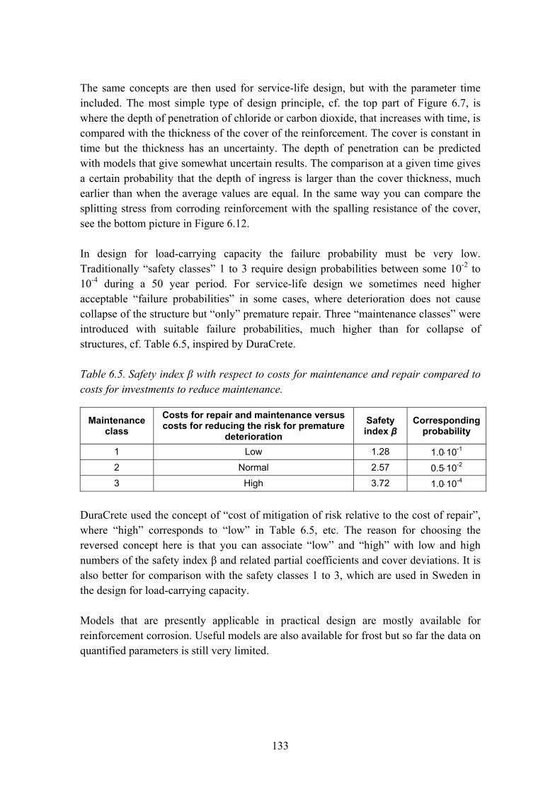
133
The same concepts are then used for service-life design, but with the parameter time included. The most simple type of design principle, cf. the top part of Figure 6.7, is where the depth of penetration of chloride or carbon dioxide, that increases with time, is compared with the thickness of the cover of the reinforcement. The cover is constant in time but the thickness has an uncertainty. The depth of penetration can be predicted with models that give somewhat uncertain results. The comparison at a given time gives a certain probability that the depth of ingress is larger than the cover thickness, much earlier than when the average values are equal. In the same way you can compare the splitting stress from corroding reinforcement with the spalling resistance of the cover, see the bottom picture in Figure 6.12.
In design for load-carrying capacity the failure probability must be very low. Traditionally �safety classes� 1 to 3 require design probabilities between some 10-2 to 10-4 during a 50 year period. For service-life design we sometimes need higher acceptable �failure probabilities� in some cases, where deterioration does not cause collapse of the structure but �only� premature repair. Three �maintenance classes� were introduced with suitable failure probabilities, much higher than for collapse of structures, cf. Table 6.5, inspired by DuraCrete.
Table 6.5. Safety index β with respect to costs for maintenance and repair compared to costs for investments to reduce maintenance.
Maintenance class
Costs for repair and maintenance versus costs for reducing the risk for premature
deterioration Safety index β
Correspondingprobability
1 Low 1.28 1.0⋅10-1 2 Normal 2.57 0.5⋅10-2 3 High 3.72 1.0⋅10-4
DuraCrete used the concept of �cost of mitigation of risk relative to the cost of repair�, where �high� corresponds to �low� in Table 6.5, etc. The reason for choosing the reversed concept here is that you can associate �low� and �high� with low and high numbers of the safety index β and related partial coefficients and cover deviations. It is also better for comparison with the safety classes 1 to 3, which are used in Sweden in the design for load-carrying capacity.
Models that are presently applicable in practical design are mostly available for reinforcement corrosion. Useful models are also available for frost but so far the data on quantified parameters is still very limited.
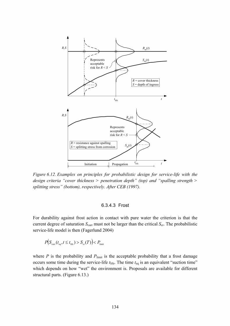
134
R,S
t
Representsacceptablerisk for R < S
Rm(t)
Sm(t)
R = cover thicknessS = depth of ingress
tlife
R,S
t
Representsacceptablerisk for R < S
Rm(t)
Sm(t)R = resistance against spallingS = splitting stress from corrosion
tlifeInitiation Propagation
Figure 6.12. Examples on principles for probabilistic design for service-life with the design criteria �cover thickness > penetration depth� (top) and �spalling strength > splitting stress� (bottom), respectively. After CEB (1997).
6.3.4.3 Frost
For durability against frost action in contact with pure water the criterion is that the current degree of saturation Scurr must not be larger than the critical Scr. The probabilistic service-life model is then (Fagerlund 2004)
( ) limitcrlifeeqcurr )(),( PTStttSP <>≤
where P is the probability and Plimit is the acceptable probability that a frost damage occurs some time during the service-life tlife. The time teq is an equivalent �suction time� which depends on how �wet� the environment is. Proposals are available for different structural parts. (Figure 6.13.)

135
Figure 6.13. Example on determination of the material property �critical degree of saturation� Scr (Fagerlund 2004).
6.3.4.4 Frost and salt
For frost durability when concrete is exposed to de-icing salts, a new model has been proposed, based on significant experience from scaling tests and field exposure (Petersson 2004; see Figure 6.14).
w/c
winter summer winter Time
-
low
high
28 days
Resistance TR
T &TR [°C<0]
After Petersson, 2004
Load T
w/c
winter summer winter Time
-
low
high
28 days
Resistance TR
T &TR [°C<0]
After Petersson, 2004
Load T
Figure 6.14. Examples of comparison between the concrete temperature T and the resistance TR against freezing during the first three winters. The structure was cast immediately before the first winter (Petersson 2004).
136
The �resistance� against damage is the concrete temperature TR that the concrete can withstand in a scaling test. The �action effect� is then the lowest temperature T that the concrete in the structure will be exposed to, when simultaneously being salted. The service-life model describes the probability for this to happen, i.e. the probability that the concrete structure will get surface scaling some time during the service-life.
Consequently, service-life design requires a series of scaling tests and a prediction of the probability of very low expected concrete temperatures of the most exposed parts of the structure. The worst periods are cold, clear nights when long-wave radiation lowers the temperature of the structure far below the air temperature.
Frost damage changes the material properties and the structure in different ways. Internal frost damage in those �unit cells� that had Scurr > Scr during freezing reduces the E-modulus and the compressive, shear and bond strength locally in these parts (Hassanzadeh & Fagerlund 2006). Surface scaling reduces the cross section of the concrete structure and the compressed zone. Surface scaling also reduces the cover thickness for the reinforcement. These effects can be considered in service-life design.
6.3.4.5 Carbonation-initiated reinforcement corrosion
The carbonation model can consider the concrete�s resistance against diffusion of carbon dioxide, the amount of calcium oxide that must be carbonated and the humidity of the cover that is determined from the humidity of the air, frequency of rain and the orientation of the concrete surface. The model is shown in Figure 6.15.
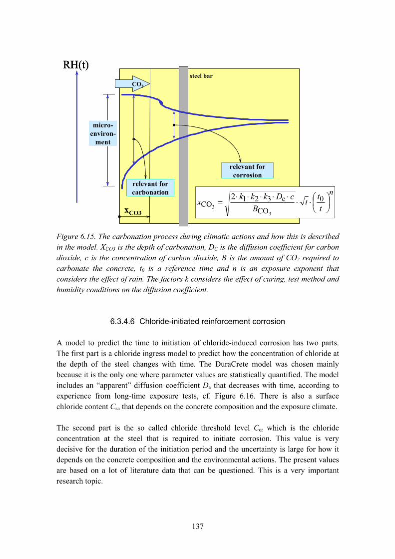
137
steel bar
xCO3
micro-environ-
ment
relevant forcorrosion
relevant forcarbonation
CO2
RH(t)
n
ttt
BcDkkkx ⎟
⎠⎞
⎜⎝⎛⋅⋅
⋅⋅⋅⋅⋅= 0
COc321
CO3
3
2
steel bar
xCO3
micro-environ-
ment
relevant forcorrosion
relevant forcarbonation
CO2
RH(t)steel bar
xCO3
micro-environ-
ment
relevant forcorrosion
relevant forcarbonation
CO2
RH(t)
n
ttt
BcDkkkx ⎟
⎠⎞
⎜⎝⎛⋅⋅
⋅⋅⋅⋅⋅= 0
COc321
CO3
3
2
Figure 6.15. The carbonation process during climatic actions and how this is described in the model. XCO3 is the depth of carbonation, DC is the diffusion coefficient for carbon dioxide, c is the concentration of carbon dioxide, B is the amount of CO2 required to carbonate the concrete, t0 is a reference time and n is an exposure exponent that considers the effect of rain. The factors k considers the effect of curing, test method and humidity conditions on the diffusion coefficient.
6.3.4.6 Chloride-initiated reinforcement corrosion
A model to predict the time to initiation of chloride-induced corrosion has two parts. The first part is a chloride ingress model to predict how the concentration of chloride at the depth of the steel changes with time. The DuraCrete model was chosen mainly because it is the only one where parameter values are statistically quantified. The model includes an �apparent� diffusion coefficient Da that decreases with time, according to experience from long-time exposure tests, cf. Figure 6.16. There is also a surface chloride content Csa that depends on the concrete composition and the exposure climate.
The second part is the so called chloride threshold level Ccr which is the chloride concentration at the steel that is required to initiate corrosion. This value is very decisive for the duration of the initiation period and the uncertainty is large for how it depends on the concrete composition and the environmental actions. The present values are based on a lot of literature data that can be questioned. This is a very important research topic.
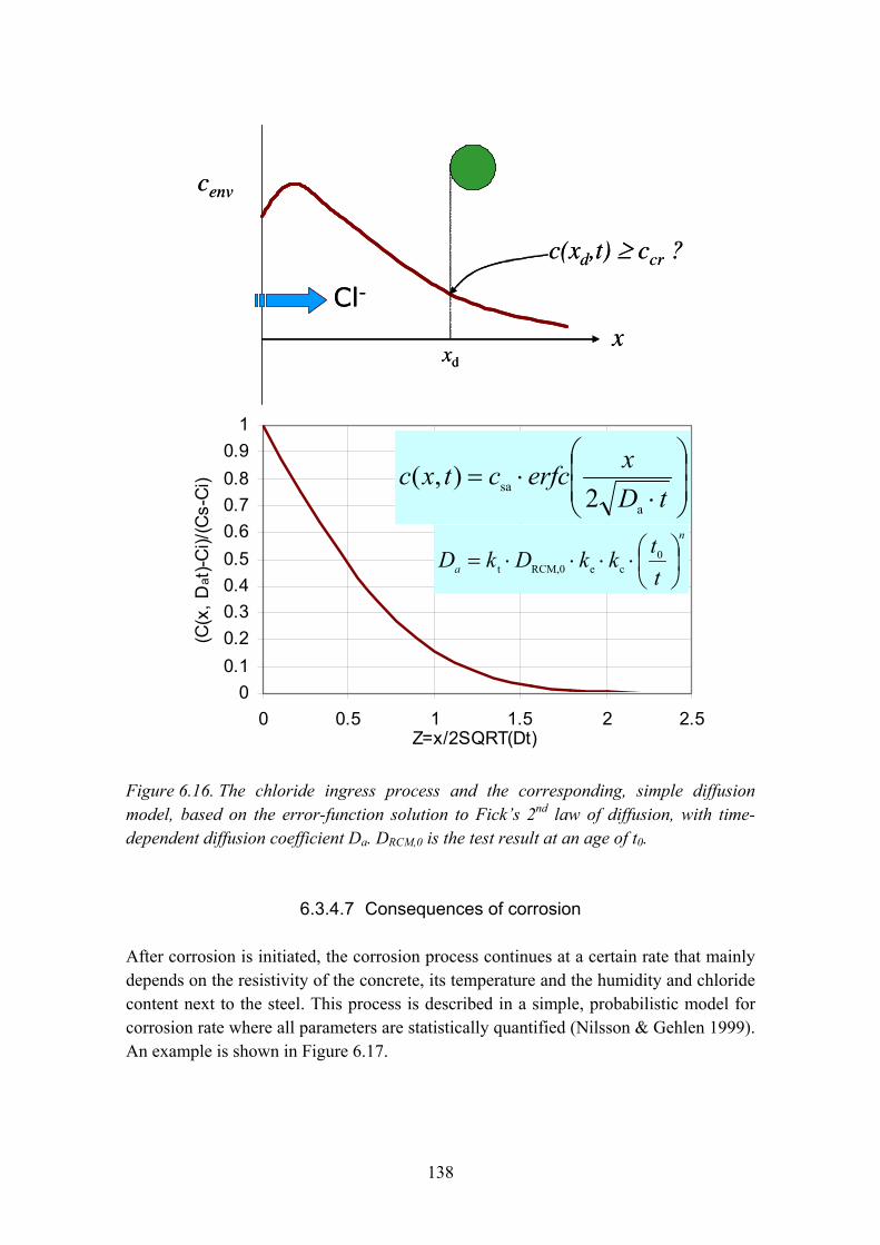
138
c(xd,t) ≥ ccr ?
cenv
x
Cl-
xd
c(xd,t) ≥ ccr ?
cenv
x
Cl-
xd
00.10.20.30.40.50.60.70.80.9
1
0 0.5 1 1.5 2 2.5Z=x/2SQRT(Dt)
(C(x
, Dat
)-Ci)/
(Cs-
Ci) ⎟
⎟⎠
⎞⎜⎜⎝
⎛
⋅⋅=
tDxerfcctxc
a
sa 2),(
n
a ttkkDkD ⎟⎠⎞
⎜⎝⎛⋅⋅⋅⋅= 0
ceRCM,0t
00.10.20.30.40.50.60.70.80.9
1
0 0.5 1 1.5 2 2.5Z=x/2SQRT(Dt)
(C(x
, Dat
)-Ci)/
(Cs-
Ci) ⎟
⎟⎠
⎞⎜⎜⎝
⎛
⋅⋅=
tDxerfcctxc
a
sa 2),(
n
a ttkkDkD ⎟⎠⎞
⎜⎝⎛⋅⋅⋅⋅= 0
ceRCM,0t
Figure 6.16. The chloride ingress process and the corresponding, simple diffusion model, based on the error-function solution to Fick�s 2nd law of diffusion, with time-dependent diffusion coefficient Da. DRCM,0 is the test result at an age of t0.
6.3.4.7 Consequences of corrosion
After corrosion is initiated, the corrosion process continues at a certain rate that mainly depends on the resistivity of the concrete, its temperature and the humidity and chloride content next to the steel. This process is described in a simple, probabilistic model for corrosion rate where all parameters are statistically quantified (Nilsson & Gehlen 1999). An example is shown in Figure 6.17.
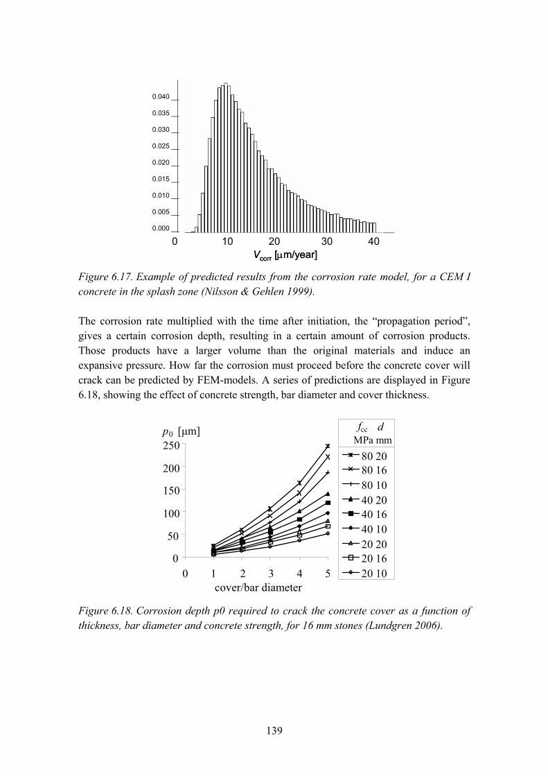
139
0.040 __
0.035 __
0.030 __
0.025 __
0.020 __
0.015 __
0.010 __
0.005 __
0.000 __
Vcorr [µm/year]0 10 20 30 40
0.040 __
0.035 __
0.030 __
0.025 __
0.020 __
0.015 __
0.010 __
0.005 __
0.000 __
Vcorr [µm/year]0 10 20 30 40
Figure 6.17. Example of predicted results from the corrosion rate model, for a CEM I concrete in the splash zone (Nilsson & Gehlen 1999).
The corrosion rate multiplied with the time after initiation, the �propagation period�, gives a certain corrosion depth, resulting in a certain amount of corrosion products. Those products have a larger volume than the original materials and induce an expansive pressure. How far the corrosion must proceed before the concrete cover will crack can be predicted by FEM-models. A series of predictions are displayed in Figure 6.18, showing the effect of concrete strength, bar diameter and cover thickness.
0
50
100
150
200
250
0 1 2 3 4 5
80 20 80 16 80 10 40 20 40 16 40 10 20 20 20 16 20 10
täckskikt/diameter
p0 [µm] d MPa mm
fcc
cover/bar diameter
0
50
100
150
200
250
0 1 2 3 4 5
80 20 80 16 80 10 40 20 40 16 40 10 20 20 20 16 20 10
täckskikt/diameter
p0 [µm] d MPa mm
fcc
cover/bar diameter Figure 6.18. Corrosion depth p0 required to crack the concrete cover as a function of thickness, bar diameter and concrete strength, for 16 mm stones (Lundgren 2006).
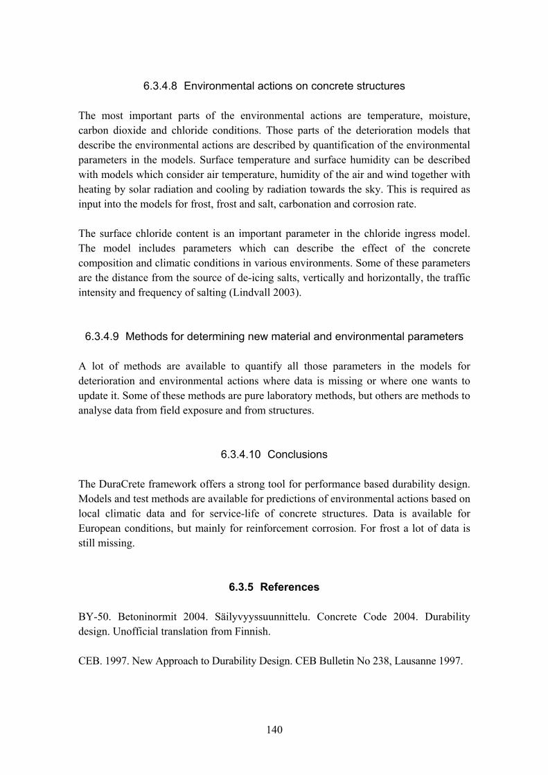
140
6.3.4.8 Environmental actions on concrete structures
The most important parts of the environmental actions are temperature, moisture, carbon dioxide and chloride conditions. Those parts of the deterioration models that describe the environmental actions are described by quantification of the environmental parameters in the models. Surface temperature and surface humidity can be described with models which consider air temperature, humidity of the air and wind together with heating by solar radiation and cooling by radiation towards the sky. This is required as input into the models for frost, frost and salt, carbonation and corrosion rate.
The surface chloride content is an important parameter in the chloride ingress model. The model includes parameters which can describe the effect of the concrete composition and climatic conditions in various environments. Some of these parameters are the distance from the source of de-icing salts, vertically and horizontally, the traffic intensity and frequency of salting (Lindvall 2003).
6.3.4.9 Methods for determining new material and environmental parameters
A lot of methods are available to quantify all those parameters in the models for deterioration and environmental actions where data is missing or where one wants to update it. Some of these methods are pure laboratory methods, but others are methods to analyse data from field exposure and from structures.
6.3.4.10 Conclusions
The DuraCrete framework offers a strong tool for performance based durability design. Models and test methods are available for predictions of environmental actions based on local climatic data and for service-life of concrete structures. Data is available for European conditions, but mainly for reinforcement corrosion. For frost a lot of data is still missing.
6.3.5 References
BY-50. Betoninormit 2004. Säilyvyyssuunnittelu. Concrete Code 2004. Durability design. Unofficial translation from Finnish.
CEB. 1997. New Approach to Durability Design. CEB Bulletin No 238, Lausanne 1997.

141
EN-206-1. 2000. Concrete � Part 1: Specification, performance, production and conformity. The European standard for concrete, approved by CEN on 12 May 2000.
Fagerlund, G. 2004. A service life model for internal frost damage in concrete. Report TVBM-3119, Building Materials. Lund: Lund Institute of Technology.
ISO. 2000. ISO 15686-1 Buildings and Constructed Assets � Service Life Planning � Part 1: General Principles. Geneva: International Standardization Organization.
ISO. 2001. ISO 15686-2 Buildings and Constructed Assets � Service Life Planning � Part 2: Service life prediction procedures. Geneva: International Standardization Organization.
Lindvall, A. 2003. Environmental actions on concrete exposed in marine and road environments and its response. Report P-03:2, Building Materials. Göteborg: Chalmers University of Technology.
Lundgren, K. 2006. Consequences of reinforcement corrosion. Calculations in Betongrapport 12.
Nilsson, L.-O. & Gehlen, C. 1999. Summary of the Statistical Quantification of the DuraCrete Resistivity Corrosion Rate Model. Work Report in DuraCrete, Brite-Euram projekt BE95-1347, CUR, Gouda, the Netherlands.
Petersson, P.-E. 2004. A service life model for scaling resistance of concrete � reflections. Contribution to fib task group 5.6, Lund, October 2004.
Swedish Concrete Association. 2007. Guidelines for service-life design of concrete structures. (In Swedish.) Betongrapport 12, 2007.
Vesikari, E. 2005. Ennus Concrete, version 1.1. Service-life design of concrete structures by the Factor Method. Espoo: VTT.
Öberg, M. 2005. Integrated life cycle design. Application to Swedish concrete multi-dwelling buildings. Report TVBM-1022, Building Materials. Lund: Lund Institute of Technology.

142
6.4 LifePlan/Ecometer
Sirje Vares and Isto Nuorkivi
6.4.1 Introduction of LifePlan and Ecometer
6.4.1.1 Ecometer
Skanska Oyj�s Ecometer is a web-based calculation tool intended for assessing the environmental attributes of residential projects. It is used to assess the energy consumption and ecological profile of a building during its life cycle from construction through the use and maintenance phases. Skanska Ecometer provides designers with the possibility to compare the ecological attributes of different design solutions and is thus a key to environmentally sound choices in project development. Using the physiology, dimensions and environmental profiles of different construction materials and products, Ecometer calculates the consumption of renewable and non-renewable energy, the consumption of renewable and non-renewable materials, and the production of greenhouse gas emissions of a project during its life cycle. Ecometer has been applied on Skanska Oyj�s residential projects in Finland. By the end of 2006, Ecometer has supported almost 300 projects overall.
6.4.1.2 LifePlan and LCA
LifePlan is a product-specific data base for service life information of building products and components.
Life Cycle Assessment (LCA) is a technique for assessing the environmental aspects and potential impacts for products. Energy use, emissions into the air and water, and the use of natural resources are among the topics reported on in environmental declarations based on LCA. For environmental declarations, the Finnish national method is compiled according to the publication �Methodology for Compiling Environmental Declarations for Building Products and Assessing Environmental Impacts of Buildings�. The methodology following the basic principles stated in the ISO standard series 14040 and 14020.
In the EKA project, VTT created and demonstrated a web-based database for the development of environmental declarations of building products. The EKA Property Set and database prototype system compile environmental data in an xml format. The database allows the user to search for environmental profiles of building materials and use them in an IFC compatible format.

143
6.4.2 Purpose of the case study
The purpose of this case study was to further improve the structure of the environmental profile database, to combine the LifePlan database and environmental profile database into a single system, and to test the combined system within Skanska Oyj�s Ekometer tool.
6.4.3 Case study
In order to use and transfer appropriate and adequate product information, the information should be organized and collected, for example, to be easily accessed through a product information library/database. In the EKA-project, data format for the LCA data was created and a prototype database was presented. In this study, VTT integrated the service life database and environmental profile database into one. Also, data transfer and presentation systems were developed. The idea was that manufacturers should be able to enter all product specific information once, into one database, and later access it through the internet. VTT created a template for LCA data entry and for data administration.
Skanska Oyj started their development work with Ecometer tool. As a part of the ICTWLORB project, Skanska began development work for reducing the amount of manual work required to carry out an Ecometer calculation. The overall aim was to make an automated link between Ecometer and the LifePlan files so that the environmental profiles of different production materials and products enter the calculation automatically. This reduces the time needed for the designer to include all the relevant parameters into an assessment and is expected to increase Ecometer�s value and usability in making various comparisons of possible design solutions. The system will also provide the possibility to further develop Ecometer to use other LifePlan information, which then provides possibilities to increase the scope and detail of Ecometer calculations and reports
To use environmental profiles from the LifePlan database as a source for the Ecometer tool, the interface between the LifePlan LCA data and the Skanska Ekometer is still needed. This work in Skanska Oyj is underway and not yet finished within the ICTWLORB project.

144
6.5 LifePlan/ModernaHus
6.5.1 Introduction of LifePlan
LifePlan is a product-specific data base for service life information of building products and components.
The LifePlan research project (Häkkinen et al. 2004) developed the content and presentation of product service life information. The objectives of the project were
− to define the contents of product service life information
− to create a product-specific database for service life information of building products and components
− to develop the structure, format and transfer of service life information, which is compliant with the future product model based software products.
Figure 6.19 shows the first page of LifePlan database system.
Figure 6.19. LifePlan database system.

145
The LifePlan project created a framework for a database where manufacturers are able to store all product specific service life information. Figure 6.20 shows the principal solution of the database. The system is a prototype system for building product data supply and storage. The principal solution was originally developed in the LifePlan research project (Siltanen 2004 in Häkkinen et al. 2004) and later further improved by Ilkka Heinonen in the Desnet (Desnet 2006) and ICTWLORB research project.
Server software:� style sheets� servlets� servlet engine� server
user interface (browser)
data input interface (browser)
data storage
databaseLifePlanXML schema
LifePlan system
Server software:� style sheets� servlets� servlet engine� server
user interface (browser)
data input interface (browser)
data storage
databaseLifePlanXML schema
LifePlan system
Figure 6.20. LifePlan database system for data supply and storage.
LifePlan data base supports service life design by presenting product-specific information for
− the estimated service life of the product
− the computational method for service life estimation
− the dependency of service life on environmental conditions and surface treatment (when relevant)
− guidelines concerning materials, structures and structural details, outdoor and conditions, use conditions, workmanship, and care and maintenance.
The LifePlan project outlines the product information as presented in Table 6.6 (Häkkinen 2004). The functions of the tool are presented in Section 6.5.1.
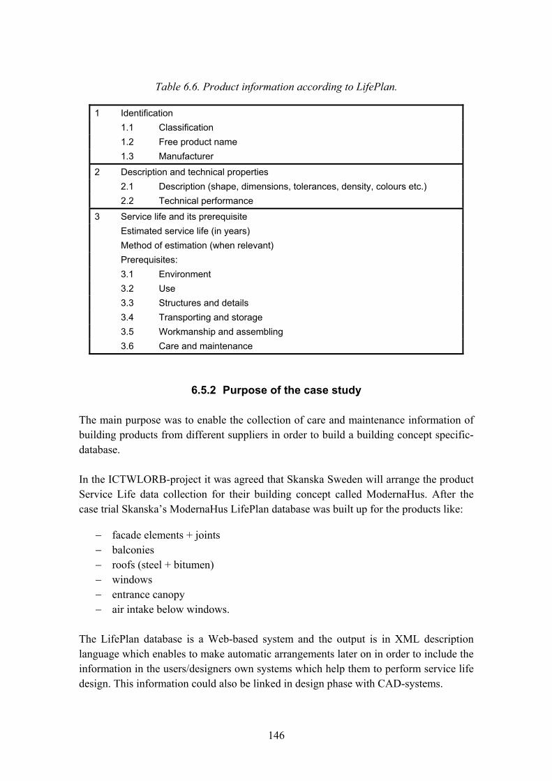
146
Table 6.6. Product information according to LifePlan.
1 Identification 1.1 Classification 1.2 Free product name 1.3 Manufacturer
2 Description and technical properties 2.1 Description (shape, dimensions, tolerances, density, colours etc.) 2.2 Technical performance
3 Service life and its prerequisite Estimated service life (in years) Method of estimation (when relevant) Prerequisites: 3.1 Environment 3.2 Use 3.3 Structures and details 3.4 Transporting and storage 3.5 Workmanship and assembling 3.6 Care and maintenance
6.5.2 Purpose of the case study
The main purpose was to enable the collection of care and maintenance information of building products from different suppliers in order to build a building concept specific-database.
In the ICTWLORB-project it was agreed that Skanska Sweden will arrange the product Service Life data collection for their building concept called ModernaHus. After the case trial Skanska�s ModernaHus LifePlan database was built up for the products like:
− facade elements + joints − balconies − roofs (steel + bitumen) − windows − entrance canopy − air intake below windows.
The LifePlan database is a Web-based system and the output is in XML description language which enables to make automatic arrangements later on in order to include the information in the users/designers own systems which help them to perform service life design. This information could also be linked in design phase with CAD-systems.
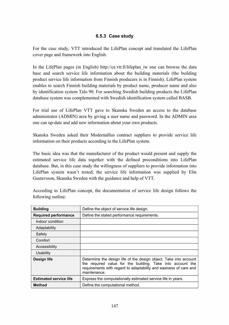
147
6.5.3 Case study
For the case study, VTT introduced the LifePlan concept and translated the LifePlan cover page and framework into English.
In the LifePlan pages (in English) http://ce.vtt.fi/lifeplan_iw one can browse the data base and search service life information about the building materials (the building product service life information from Finnish producers is in Finnish). LifePlan system enables to search Finnish building materials by product name, producer name and also by identification system Talo 90. For searching Swedish building products the LifePlan database system was complemented with Swedish identification system called BASB.
For trial use of LifePlan VTT gave to Skanska Sweden an access to the database administrator (ADMIN) area by giving a user name and password. In the ADMIN area one can up-date and add new information about your own products.
Skanska Sweden asked their ModernaHus contract suppliers to provide service life information on their products according to the LifePlan system.
The basic idea was that the manufacturer of the product would present and supply the estimated service life data together with the defined preconditions into LifePlan database. But, in this case study the willingness of suppliers to provide information into LifePlan system wasn�t tested; the service life information was supplied by Elin Gustavsson, Skanska Sweden with the guidance and help of VTT.
According to LifePlan concept, the documentation of service life design follows the following outline:
Building Define the object of service life design. Required performance Define the stated performance requirements.
Indoor condition Adaptability Safety Comfort Accessibility Usability
Design life Determine the design life of the design object. Take into account the required value for the building. Take into account the requirements with regard to adaptability and easiness of care and maintenance.
Estimated service life Express the computationally estimated service life in years. Method Define the computational method.
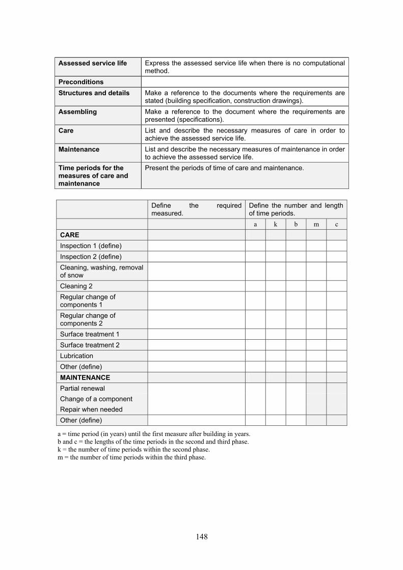
148
Assessed service life Express the assessed service life when there is no computational method.
Preconditions Structures and details Make a reference to the documents where the requirements are
stated (building specification, construction drawings). Assembling Make a reference to the document where the requirements are
presented (specifications). Care List and describe the necessary measures of care in order to
achieve the assessed service life. Maintenance List and describe the necessary measures of maintenance in order
to achieve the assessed service life. Time periods for the measures of care and maintenance
Present the periods of time of care and maintenance.
Define the required
measured. Define the number and length of time periods.
a k b m c CARE Inspection 1 (define) Inspection 2 (define) Cleaning, washing, removal of snow
Cleaning 2 Regular change of components 1
Regular change of components 2
Surface treatment 1 Surface treatment 2 Lubrication Other (define) MAINTENANCE Partial renewal Change of a component Repair when needed Other (define)
a = time period (in years) until the first measure after building in years. b and c = the lengths of the time periods in the second and third phase. k = the number of time periods within the second phase. m = the number of time periods within the third phase.

149
6.5.4 Data supply for LifePlan database, guide
Because the administrator sites were not translated into English, the following guide for data supply was made for Skanska Sweden.
a) After checking into the administration site, the user chooses a document list � �Dokumenttiluettelo�.
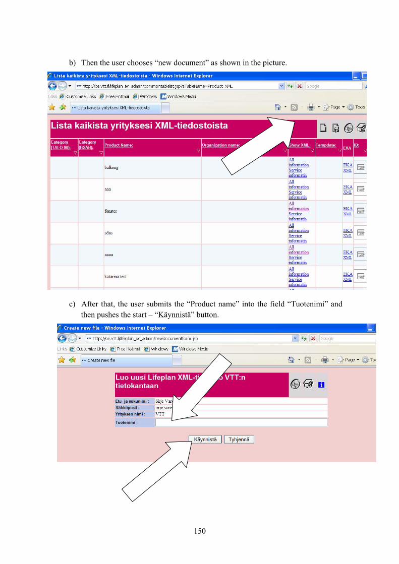
150
b) Then the user chooses �new document� as shown in the picture.
c) After that, the user submits the �Product name� into the field �Tuotenimi� and then pushes the start � �Käynnistä� button.

151
d) After that, the user will receive a table where they can submit their product data (the table is in English).
e) At the end of that page is a button to save the work, push button save.
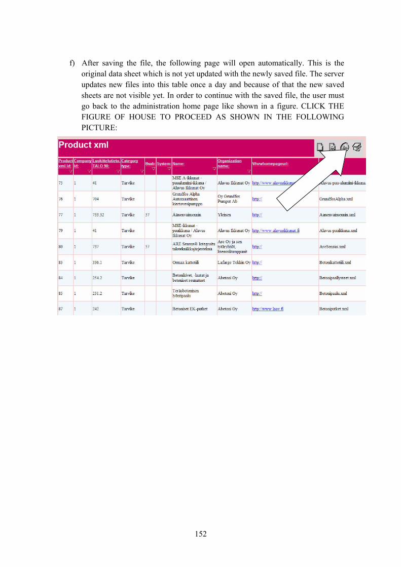
152
f) After saving the file, the following page will open automatically. This is the original data sheet which is not yet updated with the newly saved file. The server updates new files into this table once a day and because of that the new saved sheets are not visible yet. In order to continue with the saved file, the user must go back to the administration home page like shown in a figure. CLICK THE FIGURE OF HOUSE TO PROCEED AS SHOWN IN THE FOLLOWING PICTURE:
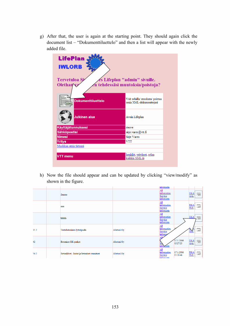
153
g) After that, the user is again at the starting point. They should again click the document list � �Dokumenttiluettelo� and then a list will appear with the newly added file.
h) Now the file should appear and can be updated by clicking �view/modify� as shown in the figure.
154
6.5.5 Discussions/problems
With the help of LifePlan database it is possible to collect building material service life, care and maintenance data for substantial number of building materials. The system helps to manage large amount of data and use it in an intelligent way. In this case study the amount of building materials dealt with was very small and because of that this benefit wasn�t achieved. However, the exercise was useful because of it was able to point out some unpractical operation of the tool (main problems appeared because of system sensitivity):
− The problem with LifePlan system might arise when data supplier filling predefined forms by using copy paste techniques, the system has a problem with some symbols which causing an error message.
− One advantage and also a problem is that the database is in xml-language. The advantage is that user could utilize the xml-files directly into their own systems, but in the other hand xml-database could cause problems, because during the data supplying processes the system attempting to write xml-files instantly. This kind of system is very sensitive to the errors, so when one supplying data with errors which the system does not understand then in the saving process, instead of saving the information might disappear or just empty xml-file might be generated. This problem could be fixed when the system forced to store information first into some other database system, for example access, and only in out print stage the translation into xml-language provided.
− One inconvenient feature of the system is the time when full information is updated. When one supplied the data and saved it, the newly saved file not appearing immediately to the database list. The server updates new files into the data table only once a day. In order to continue with the saved file, the user must go back to the administration home page and again click to the document list. Only with this procedure the system updates all data tables and previously saved file is visible.
The LifePlan system is developed as a prototype version to show the potential to collect and use service life data in an intelligent way. As the system is still prototype all usability problems are not solved yet. VTT is not suggesting Skanska Sweden to use that prototype for a long run. If Skanska Sweden is interested VTT is willing to keep LifePlan database up to date for one year and after that Skanska Sweden could develop similar database solution for the own use.
155
References
DESNET. 2006. Potentials of networking in the application of ICT solutions for life cycle designs of buildings. Research project coordinated by Tarja Häkkinen in the Finnish research programme KITARA, http://www.aka.fi/index.asp?id=04B8272BF7F64093A4991A2A61E5B474&data=1,00308B787886459385F296A5AFD4FA74,AF4A53EF7BF54A488FA4E04F83EACB0E&tabletarget=data_1&laytmp=aka_fi_sisa.
Häkkinen, T. et al. 2004. Methodology for compiling environmental declarations for building products and for assessing environmental impacts of buildings. 73 p. In: http://virtual.vtt.fi/environ/ympsel_e.html.
Siltanen, P. 2004. LifePlan database. Chapter 3 in Häkkinen, T., Vares, S. & Siltanen, P. Service life information of building products. VTT Research reports 2231. Espoo: VTT: 54 p. + app. 32 p. (In Finnish.)
6.6 Lifecycle costs for industrialised concept buildings � experiences of applying LCC spreadsheet to ModernaHus
Authors: Katarina Suber, Skanska, and Robert Larsson, Cementa
6.6.1 Introduction
This report aims to describe the experiences and results of calculating lifecycle costs for industrialised multi-family buildings using an IT-tool, named LCC Spreadsheet (Öberg 2005). The main focus has been on evaluating the applicability of this IT-tool and the needed lifecycle cost information. The testing of LCC Spreadsheet has been carried within a diploma work (Kronudd 2007). The LCC Spreadsheet has been tested on Skanska�s ModernaHus which is a concept for industrialised building process applied to multi-family buildings. This is a sub-report to the final report within the Swedish-Finish co-operation project ICTWLORB.
6.6.2 Objectives
The objectives of the performed work were
− to test the LCC Spreadsheet and VIP+ (energy calc.) on industrialised building concepts − to analyse needed input information in order to calculate lifecycle costs
156
− to identify needs of adjustments and development of LCC Spreadsheet.
The additional objective for the diploma work was to calculate and develop a LCC-formula which could be used in early phases for quick and easy calculation of LCC for different products within the ModernaHus concept. Some of these results are also presented in this report.
The test has been performed on predefine products available in the ModernaHus concept which means that technical solutions are already chosen and no specific evaluation of functional performance are made. Furthermore, the LCC Spreadsheet also includes a simplified method of LCA which has been used covering the energy use for the building during its entire lifecycle.
The applicability of using LCC Spreadsheet as a decision tool has been tested and evaluated principally from the concept owner�s point of view.
6.6.3 Introduction to LCC and ILCD
Life Cycle Cost (LCC) is used for calculating all economic costs related to a building during its life cycle; from raw material to manufacturing and further on to operation and maintenance and final disposal. LCC is a useful tool when evaluating different design alternatives with a given functionality. LCC makes it possible to justify investments with high initial costs but with low future costs (DANTES 2006). Although LCC is quite a new concept to many people, the fundamental theory has been known for many years and was applied in the manufacturing industry for more than 50 years ago (Ashworth 1993). In Sweden LCC was first introduced in 1970.
According to Ashworth, LCC could be applied in any project phase, planning, design, construction and use. An advantage of performing LCC in early phases of a project could be to avoid the most obvious risks. Some of the risks is however hard to avoid, for example a product could be old-fashioned before the end of its technical life time.
According to DANTES the complete formula for LCC could be defined as:
LCC = Cic + Cin + Ce + Co + Cm +Cs + Cenv + Cd
Cic: Initial cost Cin: Installation cost Ce: Energy costs Co: Operating costs
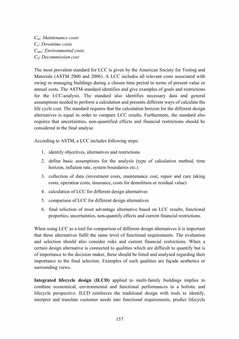
157
Cm: Maintenance costs Cs: Downtime costs Cenv: Environmental costs Cd: Decommission cost
The most prevalent standard for LCC is given by the American Society for Testing and Materials (ASTM 2000 and 2006). A LCC includes all relevant costs associated with owing or managing buildings during a chosen time period in terms of present value or annual costs. The ASTM-standard identifies and give examples of goals and restrictions for the LCC-analysis. The standard also identifies necessary data and general assumptions needed to perform a calculation and presents different ways of calculate the life cycle cost. The standard requires that the calculation horizon for the different design alternatives is equal in order to compare LCC results. Furthermore, the standard also requires that uncertainties, non-quantified effects and financial restrictions should be considered in the final analyse.
According to ASTM, a LCC includes following steps:
1. identify objectives, alternatives and restrictions
2. define basic assumptions for the analysis (type of calculation method, time horizon, inflation rate, system boundaries etc.)
3. collection of data (investment costs, maintenance cost, repair and care taking costs, operation costs, insurance, costs for demolition or residual value)
4. calculation of LCC for different design alternatives
5. comparison of LCC for different design alternatives
6. final selection of most advantage alternative based on LCC results, functional properties, uncertainties, non-quantify effects and current financial restrictions.
When using LCC as a tool for comparison of different design alternatives it is important that these alternatives fulfil the same level of functional requirements. The evaluation and selection should also consider risks and current financial restrictions. When a certain design alternative is connected to qualities which are difficult to quantify but is of importance to the decision maker, these should be listed and analysed regarding their importance to the final selection. Examples of such qualities are façade aesthetics or surrounding views.
Integrated lifecycle design (ILCD) applied to multi-family buildings implies to combine economical, environmental and functional performances in a holistic and lifecycle perspective. ILCD reinforces the traditional design with tools to identify, interpret and translate customer needs into functional requirements, predict lifecycle

158
performance of alternative technical solutions and finally rank their suitability with respect to the specific requirements (Öberg 2005). A building has to fulfil a number of different requirements by the assembled performance of its different functional attributes. Figure 6.21 present essential functional attributes and their relevance to different lifecycle phases of a building (Öberg 2005). It should be noted that these attributes may be contradictory emphasizing the importance of a holistic perspective when addressing the functional requirements in order minimize the risk of non-compliance.
⇐ Life Cycle Design ⇒
Production Use Final disposal Mechanical resistance and stability Safety in case of fire Indoor environment Safety in use Acoustics Energy use Durability Robustness and risks Life time usability Architecture Life cycle costs
⇐ In
tegr
ated
Des
ign ⇒
Environmental burden
Figure 6.21. Functional attributes and their primary relevance to specific lifecycle phases (Öberg 2005).
In contrast to LCC or Life Cycle Assessment (LCA), the ILCD-methodology enlightens differences in quality or technical performance between different design alternatives. An example of the difference between using only a LCC (or LCA) as a decision tool compared to an ILCD-methodology is illustrated by the ILCD matrix (Table 6.7). Building A and B are subjected to different technical solutions resulting in different levels of functional performance. The challenge is to find the alternative which fulfils the requirements and at the same time is the optimum comprise from the client�s point of view5. Consequently, an evaluating must include all functional requirements together with an economical and environmental analysis.
5 Note that the client could be the investor, the user or the society.
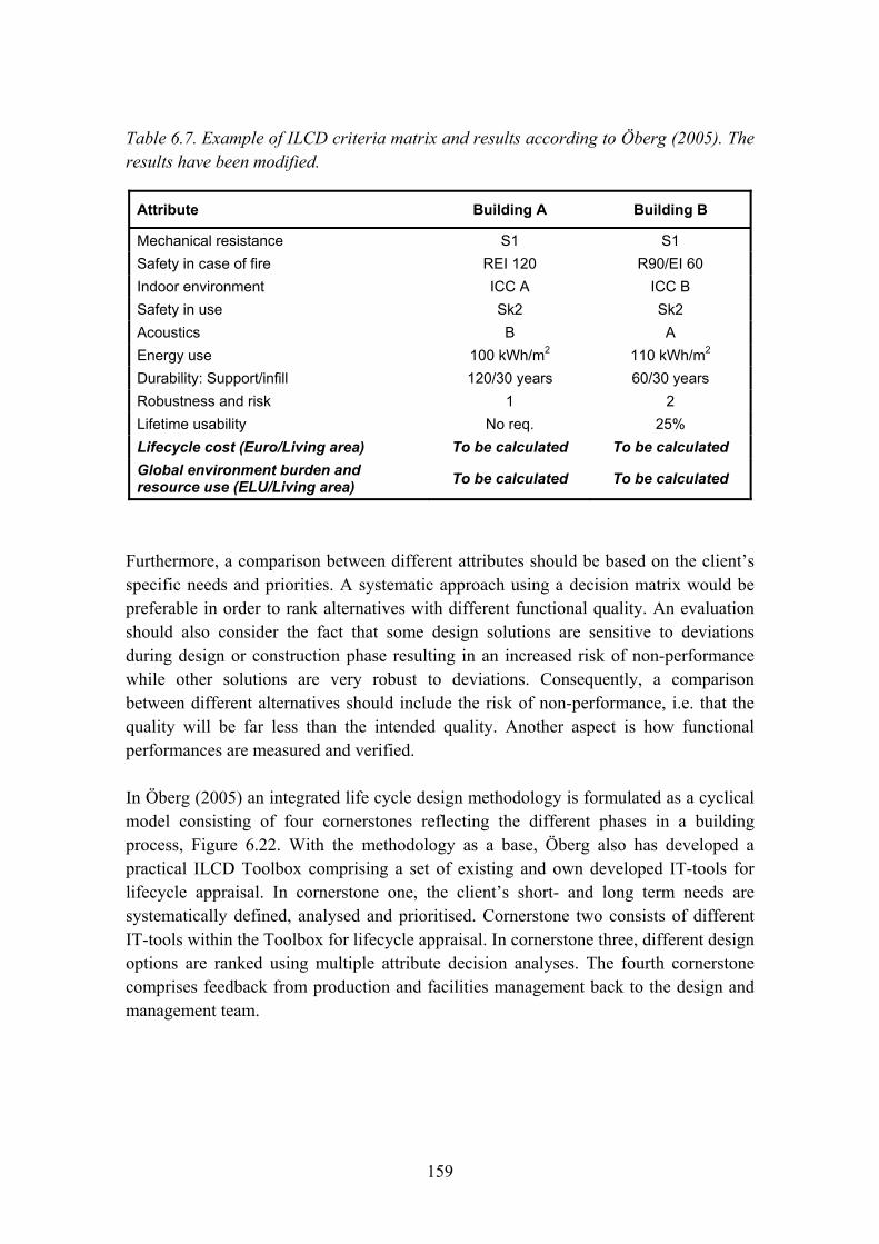
159
Table 6.7. Example of ILCD criteria matrix and results according to Öberg (2005). The results have been modified.
Attribute Building A Building B
Mechanical resistance S1 S1 Safety in case of fire REI 120 R90/EI 60 Indoor environment ICC A ICC B Safety in use Sk2 Sk2 Acoustics B A Energy use 100 kWh/m2 110 kWh/m2 Durability: Support/infill 120/30 years 60/30 years Robustness and risk 1 2 Lifetime usability No req. 25% Lifecycle cost (Euro/Living area) To be calculated To be calculated Global environment burden and resource use (ELU/Living area) To be calculated To be calculated
Furthermore, a comparison between different attributes should be based on the client�s specific needs and priorities. A systematic approach using a decision matrix would be preferable in order to rank alternatives with different functional quality. An evaluation should also consider the fact that some design solutions are sensitive to deviations during design or construction phase resulting in an increased risk of non-performance while other solutions are very robust to deviations. Consequently, a comparison between different alternatives should include the risk of non-performance, i.e. that the quality will be far less than the intended quality. Another aspect is how functional performances are measured and verified.
In Öberg (2005) an integrated life cycle design methodology is formulated as a cyclical model consisting of four cornerstones reflecting the different phases in a building process, Figure 6.22. With the methodology as a base, Öberg also has developed a practical ILCD Toolbox comprising a set of existing and own developed IT-tools for lifecycle appraisal. In cornerstone one, the client�s short- and long term needs are systematically defined, analysed and prioritised. Cornerstone two consists of different IT-tools within the Toolbox for lifecycle appraisal. In cornerstone three, different design options are ranked using multiple attribute decision analyses. The fourth cornerstone comprises feedback from production and facilities management back to the design and management team.
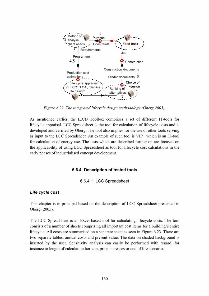
160
Purpose
Construction
Method toanalyse client needs
Life cycle appraisal: �LCC�, �LCA�, �Service life design�
Feed back
Use
Production cost estimations
Requirements
Ranking of alternatives
Programme
Construction documents
Tender documents
II IVIV
IIIIIIIIII
Choice of design
Purpose
Constraints
Construction
Method toanalyse client needs
Life cycle appraisal: �LCC�, �LCA�, �Service life design�
Feed back
Use
Production cost estimations
Requirements
Ranking of alternatives
Programme
Construction documents
Tender documents
II IVIV
IIIIIIIIII
Choice of design
12
3
4,5
6
7
8
12
3
4,5
6
7
8
Figure 6.22. The integrated lifecycle design methodology (Öberg 2005).
As mentioned earlier, the ILCD Toolbox comprises a set of different IT-tools for lifecycle appraisal. LCC Spreadsheet is the tool for calculation of lifecycle costs and is developed and verified by Öberg. The tool also implies for the use of other tools serving as input to the LCC Spreadsheet. An example of such tool is VIP+ which is an IT-tool for calculation of energy use. The tests which are described further on are focused on the applicability of using LCC Spreadsheet as tool for lifecycle cost calculations in the early phases of industrialised concept development.
6.6.4 Description of tested tools
6.6.4.1 LCC Spreadsheet
Life cycle cost
This chapter is in principal based on the description of LCC Spreadsheet presented in Öberg (2005).
The LCC Spreadsheet is an Excel-based tool for calculating lifecycle costs. The tool consists of a number of sheets comprising all important cost items for a building�s entire lifecycle. All costs are summarised on a separate sheet as seen in Figure 6.23. There are two separate tables: annual costs and present value. The data on shaded background is inserted by the user. Sensitivity analysis can easily be performed with regard, for instance to length of calculation horizon, price increases or end of life scenario.

161
Life cycle cost and environmental load. Summary sheet
Project: ParkhouseArea (m2)
Time horizon (years): 60 1420 Exchange rate �
Functional unit: Entire building 9,1Number of flats: 17
Real interest rate (%): 3,0(or expected rate of return after inflation)
ANNUAL COSTS NET PRESENT VALUE
Pricechange rel inflation (%)
Entire building (�)
� per m2
Entire building (�)
� per m2
Share (%)
Administration 0,50 8895 6 274917 194 4,6Caretaking 0,50 9987 7 308679 217 5,2Water and sewage 0,50 6710 5 264237 186 4,5Electricity 1,50 2341 2 92176 65 1,6Waste disposal 1,50 2153 2 66559 47 1,1Heating 1,50 13108 9 516184 364 8,7Insurance 0,50 780 1 24116 17 0,4Other annual cost 0,50 2965 2 91639 65 1,5Periodic maintenance 0,50 14195 10 438745 309 7,4
Initial cost (production) 0,50 112883 79 3489065 2457 59,0Property tax 0,00 5462 4 151151 106 2,6Value (-) or cost at end of life 0,50 6414 5 198252 140 3,4
Sum 185892 131 5915720 4166
Socio economy according to: EPS 200Environmental discount rate (%): 0 Exchange rate � 1
Environmental assessment ANNUAL TOTAL LIFE CYCLE
Entire building (�)
� per m2
Entire building (�)
� per m2
Share (%)
Production 1400 1 83972 59 14,2Operation 9859 7 591569 417 87,2End of life cycle 53 0 3186 2 0,5
Sum 11312 8 678728 478
kWh/m2Annual energy use for heating including hot water 140
Figure 6.23. Example of the summary sheet in LCC Spreadsheet from Öberg (2005).
Each sheet consists of information about typical average costs, that can be used instead of specific figures, at early phases of a project, or at other occasions when detailed information is not available. The different cost items are
− production (initial cost) − administration − caretaking − water and sewage − electricity − waste disposal − heating − insurance − other annual cost − property tax − periodic maintenance − value or cost at end of lifecycle (residual value).
162
The LCC Spreadsheet is organised to be in line with practice for facilities management of multi-family housing in Sweden and as given by national statistics, and with the Norwegian LCC standard for construction assets, NS 3454 � Life cycle costs for building and civil engineering work. It is easy to expand or modify the spread sheet to suit any other particular configuration. The cost items are clustered into:
− Capital costs. Initial cost, tax and residual cost (or value) at end of life cycle.
− Operating and management costs that recur annually.
− Periodic maintenance. Scheduled maintenance and replacements that occur with longer intervals than one year.
The discount rate selected for the LCC calculation has a significant effect on the result. A high discount rate implies for a short economical perspective where future costs becomes less important. By using a low discount rate investments which yield profits during a long time horizon becomes more important. In the LCC Spreadsheet model, the user arbitrarily selects the real interest rate and price increase (in relation to inflation) for the specific cost category. The programme calculates the resulting discount rate, see Figure 6.23. Sensitivity analyses are easily undertaken, for instance to determine the effect of different price increase scenarios, or with regard to the economical planning criteria applied by the client.
6.6.4.2 Life cycle cost data
The programme contains data on building and operating costs which has been gathered and analysed by Öberg (2005). For periodic maintenance, the tool contains a spreadsheet with information on maintenance intervals, technical service life and cost for maintenance activity, which is based on data from SABO (2001). The data for periodic maintenance have been updated by the diploma workers with actual information gathered and supplied by SABO.
6.6.4.3 Calculation horizon
One principal question by life cycle costing is how the calculation horizon may affect the result. Two aspects must then be considered:
− When is a reasonable balance between initial and operating costs achieved, and thus a representative long-term cost profile obtained?
− Will the calculation horizon effect the relation between the alternatives?

163
According to Öberg (2005), a minimum time horizon of 60 years (but preferable 100 years) gives a satisfactory balance between investment and operation costs.
6.6.4.4 End of the life cycle
The end of the life cycle can either release a cost for demolition, and final disposal, or a gain from sales of the building. It may be difficult to predict this at the design phase. In the LCC tool there is a specific sheet covering the end of life cycle. Different scenarios can be selected, or a specific cost or residual value, if known. This concerns cases when time for actual usage of the building is equal to the economical calculation horizon.
However, in many other cases, the house owners are interested in making an economical calculation with substantially shorter time horizon. It should be noted that this is per definition not a LCC. However, it�s not unusual to perform economical calculations with short time horizons it will be commented here as well.
In a traditional economical calculation with short time horizon, the return of invested capital for a multi-family building consists of the annual net balance (incomes minus operation costs) and the change of the property�s value. In Figure 6.24, the development of selling price for multi-family houses is compared to the inflation (SCB 2007 and Industrifakta 2007). The price level for multi-family buildings is expressed as the ratio between selling price and the assessed value. It�s concluded that the development in price level for multi-family houses has increased more than the inflation.
Development of price level for multi-family buildings and the consumer price level
10
100
1000
10000
1960 1965 1970 1975 1980 1985 1990 1995 2000 2005
Year
Loga
rith
mic
sca
le
Ratio: Selling price/Assessedvalue (Multi-family houses)Consumer price level
Figure 6.24. Development of price levels for multi-family houses and inflation from 1960 to 2006. Index 1960 = 100 (SCB 2007 and Industrifakta 2007).

164
In addition, the house owner has had a running net profit from operation of the building. In a long time perspective, it�s therefore reasonable to assume that the residual value increases in the same rate as the return of the investment. Of course this relationship will vary strongly between different geographic regions.
At shorter time horizons, this will be restrained by the companies� profit and loss account, the access of capital (terms of loan) etc. In the diploma work, an economic calculation with a time horizon of 20 years has been performed. The results show that if residual values which not are adjusted to inflation and return of investment are used, the selection of calculation horizon will have a significant importance to the results.
Also environmental aspects are dealt with here. In case there is a residual value attached to the building the environmental burden of destruction and final disposal is not released. This implies that the end of life scenario here either refers to ownership (second hand value) or building life cycle (final disposal cost and environmental burden).
6.6.4.5 Verification of the LCC tool
Statistical data on costs were collected from several sources and a field-survey comprising four modern concrete multi-family houses was undertaken to compare real operating costs with the predictions according to the tool. The result of this investigation was presented by Johansson and Öberg (2001). Energy costs, periodic maintenance and the initial production costs have the largest impact on the life cycle cost. These are directly dependent on design and selection of materials and are therefore of primary interest by ILCD.
Calculation of environmental costs
Energy consumed during the user phase is defined as the most important global environmental burden Adalberth (2000). Therefore energy use has been selected as a simplified environmental life cycle indictor Öberg (2005). LCC Spreadsheet includes a simplified method that incorporates the whole building, monitoring the energy use and the related environmental consequences.
Simplified environmental assessment method
Given the amount of energy consumed and the particular energy source used, the tool estimates 1) the resulting emissions to air of CO2, NOx and So2 and 2) the socio-economic cost of these emissions in terms of air pollution and resource use. The �socio-economy� is calculated according to EPS 2000 (Steen 1999).

165
The discount rate for the environmental, socio-economic estimations is separated from the strictly economical which is a well established practice. As a default value this is set to 0 indicating that the environmental burdens are as significant in the future as they are today.
A database on emissions from different energy sources was developed based on LCAiT (1996) and connected to socio-economic costs according to EPS 2000.
It is acknowledged that the selection of a limited number of environmental stressors (CO2, NOx, SO2) underestimates the total environmental burden. However, LCA studies on energy and also cement and concrete, such as Vold and Rönning (1995), show that these particular stressors contribute to more than 90% of the total environmental burden, and furthermore that the other stressors occur in good correlation with the ones selected here. The total environmental burden is thus underestimated with a maximum of 10% in relation to the importance of other attributes. This simplification was done in order to make the model practical to use. If requested it can easily be expanded with any other environmental stressors. The energy carriers included in the model used in the toolbox are electricity (Swedish average), district heating (Swedish average), natural gas, diesel and oil. Other energy carriers can be added if needed.
6.6.4.6 Full LCA method
The ILCD Toolbox also consists of a generic IT-tool providing the possibility for more detailed environmental assessment. This IT-tool is based on the generic LCAiT (1996) tool and the current version is limited to the structural frame. It can be expanded to include any other type of material or component that is incorporated into the building.
The LCAiT tool consists of an inventory procedure where the user graphically defines a process tree. The tree contains boxes for materials or processes and boxes for transportation of materials. Generic environmental data sets are included in the programme, and the user adds any necessary specific data for materials and processes. The generic datasets include a much more comprehensive list of environmental stressors, than the aspects included in the simplified procedure. The programme calculates the environmental stressors occurring as a result from the process from materials flows and energy use. Any kind of environmental stressor can be included in the inventory, provided that the relevant data are stored into the boxes of the process tree.
Typically the following stressors are mapped:
− emissions of different substances to air and water − the waste generated − use of energy and resources.
166
The result is a list of the quantified stressors. This list is exported to a spreadsheet model, developed by the author that performs the impact assessment, according to standard LCA procedure. As in the simplified energy model the EPS weighting method (Steen 1999) is applied. This also enables comparison between the environmental burden of the building frame and total building life cycle.
6.6.4.7 VIP+ (energy balance calculation)
Acceptable operating costs and good environmental and functional performance all relate to the energy balance of a building. Energy is used through all life cycle phases of a building from the extraction of raw materials to demolition and recycling. According to Adalberth (2000), the user phase comprises 85% of the total energy use during the lifetime of a building.
Traditionally, the energy related design of the climate shell of a residential building is conducted by the architect and structural engineer, and is primarily focused on the average U-value of the climate shell. The total energy performance of a building, however, also depends on a number of other properties and aspects, such as air tightness, thermal storage, solar gains and electricity used for lighting etc.
The commercially available VIP+ is a dynamic programme that manages energy supply from space heating, solar radiation, internal gains (people, appliances), heat recovery from ventilation and energy release by transmission, ventilation, air leaks, hot water production, and cooling. One useful feature of VIP+ is that also indoor temperatures are computed, which allows an assessment of thermal comfort for the specific design alternatives. It should be pointed out that VIP+ primarily is an energy balance programme for the design of the climate shell, and that in general cases, other types of programmes should be used for the thermal comfort related design in general cases. For a normal Swedish residential building with limited window areas, no cooling and moderate internal gains, VIP+ is however deemed to be a sufficient tool to predict indoor temperatures.
6.6.5 Description of ModernaHus
ModernaHus is one of the most recent initiatives towards an industrialised building process in Sweden. The concept which has been developed by Skanska, is adapted to multi-family housing and was launched in 2005.

167
The concept includes both slab and point blocks in 3 to 8 stories. The fundamental idea behind the concept is a high level of repetition and standardisation of processes, building parts and components. System thinking and modularisation is also important in order to achieve products with high flexibility. Developed and adapted purchase and logistic solutions together with specialisation of employees and supporting tools are also important ingredients in the concept.
All building parts and components have already been analysed in detail during the development process. ModernaHus could be applied in different levels; as a complete product with no possible changes or as a concept with possibility for the client to adapt the concept in order to fulfil specific needs. The three top levels in Figure 6.25 are referred to ModernaHus.
Figure 6.25. Characterisation of the different levels in ModernaHus.
The project delivery process consists of well defined phases including sophisticated building information models of the actual building. The first phases include early and detail design and production planning. Not until all information and production documents are finalised and accepted, the manufacturing and assembly phases are allowed to start.
The foundation consists in general of a concrete slab and concrete footings. The internal load bearing walls consist of prefabricated concrete elements and the façade walls are built up by concrete sandwich elements. The sandwich elements are prefabricated and delivered to the building site with complete painted surface and installed windows. The floor structure consists of prefabricated concrete hollow core slabs. The roof structure consists of prefabricated steel elements which are assembled on-site. The bathrooms are also manufactured off-site and delivered as volumes complete with piping, sanitary
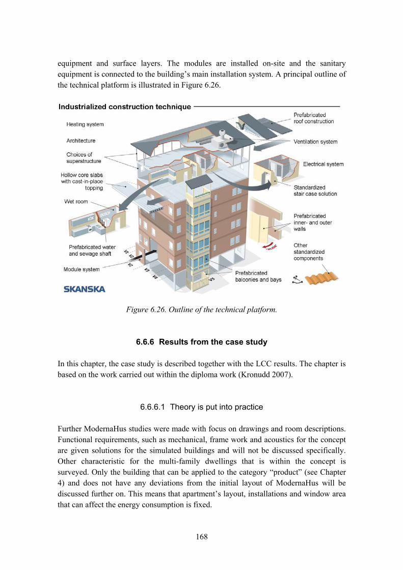
168
equipment and surface layers. The modules are installed on-site and the sanitary equipment is connected to the building�s main installation system. A principal outline of the technical platform is illustrated in Figure 6.26.
Figure 6.26. Outline of the technical platform.
6.6.6 Results from the case study
In this chapter, the case study is described together with the LCC results. The chapter is based on the work carried out within the diploma work (Kronudd 2007).
6.6.6.1 Theory is put into practice
Further ModernaHus studies were made with focus on drawings and room descriptions. Functional requirements, such as mechanical, frame work and acoustics for the concept are given solutions for the simulated buildings and will not be discussed specifically. Other characteristic for the multi-family dwellings that is within the concept is surveyed. Only the building that can be applied to the category �product� (see Chapter 4) and does not have any deviations from the initial layout of ModernaHus will be discussed further on. This means that apartment�s layout, installations and window area that can affect the energy consumption is fixed.

169
The simulations were made on two ModernaHus pilot projects, a six story point block building in Kristianstad and a five story slab block building in Örebro. In addition, tests have also been performed on 3 to 8 stories for both building types. The locations of the simulations are Stockholm, Göteborg, Malmö, Östersund, Kiruna, Kristianstad and Örebro. These cities have been chosen to analyze the effect of different climate conditions.
For the reference cities (Stockholm, Göteborg, Malmö, Östersund and Kiruna), point block buildings with 3, 6 and 8 stories and slab block building with 3, 5 and 8 stories were simulated. In addition, the pilot projects were tested in respectively city.
In the ILCD toolbox, some of the values comes from SCB:s (Statistics Sweden, central government authority for official statistics) where statistics is available for Stockholm, Göteborg, Malmö and municipalities with more that 75 000 inhabitants, municipalities with less that 75 000 inhabitants and national average (SCB 2005). In addition to the different energy need, construction cost and residual value, the variation in the statistical costs will differentiate.
Within the ModernaHus concept, the floors are identical except for the ground floor and the top floor. With help of room descriptions from the product catalogue, the care and maintenance cost is calculated. The cost is also confirmed in Skanska�s calculation programs. When specific care and maintenance costs were not available for ModernaHus, general statistics from SABO (the Swedish Association of Municipal Housing Companies) were used instead. The project that has been built within the concept is also right of tenancy.
6.6.6.2 LCC Spreadsheet
In the LCC Spreadsheet, information about national average statistics is provided at the bottom of each sheet. This can be used when specific company or project data is not available although it is preferable to avoid general data. All the available statistics have been updated on each spreadsheet. When performing calculations and analyzing the results, living area is used.
The LCC Spreadsheet that has been updated with national average statistics is complemented with specific values depending on building type and geographical position. The definition of production cost differentiates, but according to the SCB definition it includes cost for building site, costs for connecting to water and sewage, electricity and district heating, construction cost and other costs for the property developer.

170
The idea of performing the simulations is to make a general model for calculating life cycle costs for ModernaHus. When using the definition above on production cost it also includes building site. The cost for the land differentiates very much depending on the location.
Since ModernaHus is a concept, this way of using the production cost is not the best solution since it should be applied to coming projects. In the diploma work, the production cost was replaced by the construction cost, which means calculated cost for the concept. Hereby the other costs given above are not included although the design cost will be included in the construction cost. The result of the simplification is that the LCC calculations will not be comprehensive. In the LCC definition, all cost during the life cycle should be considered, which is almost impossible, but such a large cost as land will affect the result in such a way that it can not be neglected. Nevertheless the results from the calculations will still be referred to as LCC in the text.
ModernaHus also includes new building components that are not available in the SABO statistics. This means that some care and maintenance cost for the life cycle was not available. Since the ModernaHus concept is constantly improving, the building components might also change during the concept development.
As mentioned in Section 6.6.4, estimating the residual value is difficult. The residual value is equal to the market value which depends on the quality of the building, the geographic location and balance between supply and demand. Interest rate was set to 4% and the inflation was assumed to be 2% which is a common assumption. Other costs were assumed to change with the same rate as the inflation, except for the environmental costs. These were assumed to increase more since the environmental issues are constantly getting more focus in the society. With this argument the energy price is set to 2% more than inflation. The cost estimate timeframe is set to 60 years. In the diploma work, an economical calculation with a time horizon of 20 years was carried out which revealed that the results were strongly dependent on the chosen residual value.
6.6.6.3 Energy calculation using VIP+
The energy cost is an important part of the life cycle cost, both economically and environmentally, therefore the national average numbers was not used in the simulations in the spreadsheet. The use of electricity and heating need was instead calculated in VIP+.

171
In LCC calculations, the indoor temperature is often set to 20 °C even if the actual indoor temperature often is about 22 °C. The minimum temperature is therefore set to 22 °C in the simulations. A sensitivity analysis was also made with the lower indoor climate for the pilot projects.
Since ModernaHus has material and constructions parts that are chosen to reduce the energy need, it was important to add those components to the program to get as accurate values as possible. Other issue handled was the geographical position of the buildings.
The result from the energy calculations in VIP+ is presented as a graph which shows the energy balance during one year. Figure 6.27 shows the energy balance for a six storey point block building.
Weekly energy supply
Weekly energy lossesTransmission Air leakageVentilation Hot Tap Water Passive coolingReference building
Free gains (Solar rad.) Free gains (Process) Bought energyRecovery heat pump Recovery ventaltionRecovery sun panels Reference buildingFree gains (people) Reference building
Weekly energy supply
Weekly energy lossesTransmission Air leakageVentilation Hot Tap Water Passive coolingReference building
Free gains (Solar rad.) Free gains (Process) Bought energyRecovery heat pump Recovery ventaltionRecovery sun panels Reference buildingFree gains (people) Reference building
Figure 6.27. Energy balance for a six storey point block building.
The results from the VIP+ calculations are then transferred to the LCC Spreadsheet together with other energy related information.
6.6.6.4 Basis for calculations
Table 6.8 shows the parameters used for the energy and LCC calculations for each building. The same data is used, independent of the geographical location.
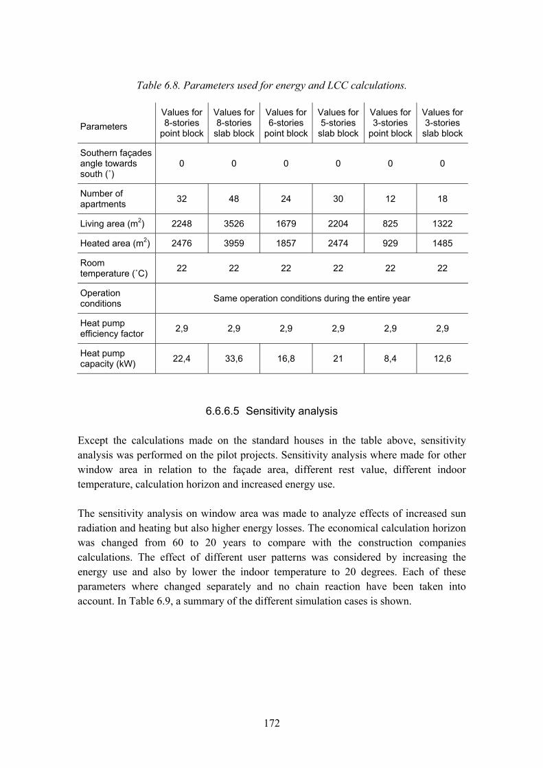
172
Table 6.8. Parameters used for energy and LCC calculations.
Parameters
Values for 8-stories
point block
Values for 8-stories
slab block
Values for 6-stories
point block
Values for 5-stories
slab block
Values for 3-stories
point block
Values for 3-stories
slab block
Southern façades angle towards south (û)
0 0 0 0 0 0
Number of apartments 32 48 24 30 12 18
Living area (m2) 2248 3526 1679 2204 825 1322
Heated area (m2) 2476 3959 1857 2474 929 1485
Room temperature (ûC) 22 22 22 22 22 22
Operation conditions Same operation conditions during the entire year
Heat pump efficiency factor 2,9 2,9 2,9 2,9 2,9 2,9
Heat pump capacity (kW) 22,4 33,6 16,8 21 8,4 12,6
6.6.6.5 Sensitivity analysis
Except the calculations made on the standard houses in the table above, sensitivity analysis was performed on the pilot projects. Sensitivity analysis where made for other window area in relation to the façade area, different rest value, different indoor temperature, calculation horizon and increased energy use.
The sensitivity analysis on window area was made to analyze effects of increased sun radiation and heating but also higher energy losses. The economical calculation horizon was changed from 60 to 20 years to compare with the construction companies calculations. The effect of different user patterns was considered by increasing the energy use and also by lower the indoor temperature to 20 degrees. Each of these parameters where changed separately and no chain reaction have been taken into account. In Table 6.9, a summary of the different simulation cases is shown.

173
Table 6.9. Summary of simulated cases.
Slab block Point block
Nbr of stories Nbr of stories
Geographic analysis
3 5 8 3 6 8
Kiruna • • • • • • Östersund • • • • • • Stockholm • • • • • • Göteborg • • • • • • Malmö • • • • • • Kristianstad • Örebro • Sensitivity analysis: 25% windows • • 30% windows • • 35% windows • •
Indoor temp. 20 °C • • Economic calc. horizon = 20 year • •
6.6.6.6 Calculation results
VIP+
As expected, the energy needed for heating is larger in the northern parts of Sweden because of change in climate. In the same way the electricity consumption is higher. The energy need per area unit is decreasing with more apartments, floors or living area per building. In the simulations, the total energy use is less for slab blocks compared to the point block buildings. In Table 6.10 below the energy use for ModernaHus buildings located in Malmö is given. A slab block building has a higher heating efficiency than a point block because of more living area, less slab and roof area.
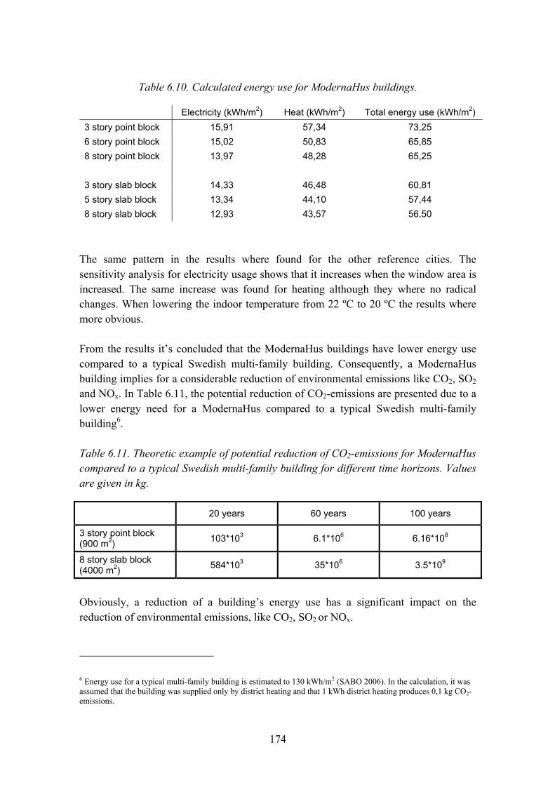
174
Table 6.10. Calculated energy use for ModernaHus buildings.
Electricity (kWh/m2) Heat (kWh/m2) Total energy use (kWh/m2) 3 story point block 15,91 57,34 73,25 6 story point block 15,02 50,83 65,85 8 story point block 13,97 48,28 65,25 3 story slab block 14,33 46,48 60,81 5 story slab block 13,34 44,10 57,44 8 story slab block 12,93 43,57 56,50
The same pattern in the results where found for the other reference cities. The sensitivity analysis for electricity usage shows that it increases when the window area is increased. The same increase was found for heating although they where no radical changes. When lowering the indoor temperature from 22 ºC to 20 ºC the results where more obvious.
From the results it�s concluded that the ModernaHus buildings have lower energy use compared to a typical Swedish multi-family building. Consequently, a ModernaHus building implies for a considerable reduction of environmental emissions like CO2, SO2 and NOx. In Table 6.11, the potential reduction of CO2-emissions are presented due to a lower energy need for a ModernaHus compared to a typical Swedish multi-family building6.
Table 6.11. Theoretic example of potential reduction of CO2-emissions for ModernaHus compared to a typical Swedish multi-family building for different time horizons. Values are given in kg.
20 years 60 years 100 years
3 story point block (900 m2) 103*103 6.1*106 6.16*108
8 story slab block (4000 m2) 584*103 35*106 3.5*109
Obviously, a reduction of a building�s energy use has a significant impact on the reduction of environmental emissions, like CO2, SO2 or NOx.
6 Energy use for a typical multi-family building is estimated to 130 kWh/m2 (SABO 2006). In the calculation, it was assumed that the building was supplied only by district heating and that 1 kWh district heating produces 0,1 kg CO2-emissions.

175
LCC Spreadsheet
The calculated energy use was served as an input into LCC Spreadsheet.
The results from the simulations show that the annual cost per living area is decreasing with the number of floors, Figure 6.28.
Annual costs in relation to number of stories for residential
buildings
80
82
84
86
88
90
92
94
1 2 3 4 5 6
Number of stories
Ann
ual c
ost (
EUR
/livi
ng a
rea)
Slab block
Point block
Figure 6.28. Calculated annual costs in relation to number of stories for slab and point block buildings.
All the point block buildings, even the ones with 3 stories, have a lower LCC per square meter than the slab block buildings of different heights. Other parameter that gives variation in the results is the location of the building. More parameters than the energy use will be affected from the location. For example, the annual cost for administration and maintenance differentiate between the reference cities. This has resulted in a lower life cycle cost for a typical building in Östersund compared to Göteborg in spite of the geographical difference.
When duplicating the energy need for Söderberg it increased the annual costs. The variation of the window area from 25% to 35% did not give any great differences in the energy consumption and did not affect the annual cost in a vast way. The lowered indoor temperature gave a greater change in the result.

176
6.6.7 Analyse and conclusions
Comments to the LCC-results
The results from the simulations showed that the annual cost per living area is decreasing with the number of floors for both slab and point block buildings. The results also showed on higher annual costs for slab blocks compared to point blocks even though that the slab blocks were proven to be more energy efficient. However, this could be explained by a higher construction cost for the slab block resulting in a higher impact on the annual cost for a slab block (in relation to other cost items) compared to a point block. It�s important to note that the calculations were done without consider the effect of a higher residual value according to the discussion in Section 6.6.4.
In this study, the LCC Spreadsheet has been tested mainly from the concept owner�s perspective. It�s evident that factors like input information quality and availability, selection of discount rate and residual value are important to the reliability and usability of the LCC results. Furthermore, the functional quality have been given by the chosen buildings and not evaluated separately in this study, i.e. ILCD. However, the functional quality is important not only for the concept owner but also to the users and the society in general. Considering the socio economic value, also the environmental benefits (like reduction of CO2, SO2, NOx) are important to consider.
Energy use is essential to the environmental profile of a building. Considering the lifecycle, a reduction of energy use results in a significantly reduction of environmental emissions. Furthermore, the energy use is one of the largest cost items that are reasonable easy to control and influence by the concept developer. The calculations also confirmed the importance of the choice of discount rate and residual value. The calculation horizon becomes more important when high values of price changes in relation to the inflation are used. In this study the energy price was assumed to increase 2% more than the inflation. A longer calculation horizon (60 years ore more) is preferable when it comes to residential buildings in order to take account for major investments like repair and change of installations. In a long time perspective, it�s reasonable to assume that the residual value increases in the same rate as the return of the investment. However, in order to reduce the impact of variations and uncertainties in residual value, calculations horizons of 60�100 years is preferable. The choice of appropriate discount rate is important to the result as well. A low value implies that future cost becomes more important and enables a long term perspective where materials and solutions with longer service life and lower care and maintenance costs are favoured.

177
The case study shows that it�s possible to calculate LCC to different buildings in the ModernaHus concept. Most likely, industrialised building processes have better opportunities to fully utilize LCC (and ILCD) methods compared to traditional building processes. The ambition of the diploma work to create a statistical base of LCC to ModernaHus was in some extent hindered by the lack of available product specific data and by the fact that the more generalised data was not detailed enough.
6.6.7.1 LCC methodology applied to an industrialised building process
There is a great potential of using LCC when designing buildings but LCC alone is not the right choice of method when comparing two different design solutions. It is essential to also consider the functional performance of a given building design. An integrated lifecycle design methodology as described in Öberg (2005) seems to be more an appropriate method where economical, environmental and functional requirements are considered in a holistic way over the lifetime of the building. ILCD seems to be especially well suited when it comes to industrialised building processes with high repetition of technical solutions and systematic re-use of knowledge and information.
The experience of the case study revealed the importance of having access to data with high quality and resolution in order to perform reliable LCC calculations. For example, it�s necessary to have access to product specific information like periodic maintenance and caretaking but also to more generalised information like municipal taxes and price levels on electricity and district heating. In the case study, specific product information was in general not available for ModernaHus and therefore data supplied from the Swedish Association of Municipal Housing Companies (SABO) was used instead as input to LCC Spreadsheet. Of course, this had an impact to the reliability of the LCC-results. It was also concluded that available statistical information about municipal taxes and administration costs wasn�t detailed enough.
In order to fully utilize the potential of LCC as a decision tool in the development of ModernaHus concepts, specific and general data have to be gathered, statistically analysed and stored for easy accessibility. By systematically gathering general and specific data from existing and new ModernaHus projects, it would be possible to apply statistical analysis which would increase the quality in the needed information and thus increase the usability of LCC-methodology. In a long term perspective, information about residual values could also be available. Lifecycle cost calculations together with functional requirements assessment could be used in the development of new concepts (platforms) within the ModernaHus where different design options are evaluated. Calculations could be made for all possible technical solutions within the concept in order to create a statistical base to formulate LCC key-figures and formulas to be used
178
in the project delivery phase. The gathering of data could be performed in co-operation with internal or external clients and facility management organisations but also together with material suppliers. Furthermore, some kind of function within the organization is probably needed, responsible for the co-ordination and management of general and specific product information.
LCC Spreadsheet applied to an industrialised building process
LCC Spreadsheet contains all important cost items in order to perform a reliable LCC calculation. However, this kind of information is not always easy accessible and more generalised information have to be used resulting in less reliable results. The simplified LCA-method included in LCC Spreadsheet is limited to the energy use of a building�s lifecycle and therefore underestimates the real environmental impact. At present, the ILCD Toolbox includes a full LCA method on a concrete building frame covering all important environmental stressors. The full LCA is based on the generic LCAiT tool and can be expanded to include any other type of material or component that is incorporated into the building. Consequently, one interesting idea would be to enlarge the LCAiT-module in order to cover materials and building components which are used in the ModernaHus-concept. However it should be noted that a crucial aspect is that complete, robust and reliable quantitative environmental data for building products are only available for a limited number of products and materials. Furthermore, a complete LCA method also requires a significant increase of detailed information implying more effort in gathering data and performing necessary calculations.
When it comes to other input information needed in LCC Spreadsheet, there are different possible improvements. One preferable option is to create some kind of database covering needed information about municipals and bigger cities. For this purpose, the sources used in the case study would be preferable to use as a basis. The information should also include specific data on price levels concerning electricity and district heating for each municipal and city. Concerning the general kind of information needed in LCC Spreadsheet, an interesting improvement would be to have a functionality which enables a quick and easily change of geographic dependent parameters such as cots for administration, caretaking, water and sewage, electricity, district heating, waste disposal and insurance. When knowing the location of the building this kind of information would be generated automatic by the programme.
Finally, another interesting improvement to LCC Spreadsheet would be to develop a digital connection to building information models (BIM�s) or product information data bases which would increase the efficiency of manage information significantly. The idea is to develop a digital connection between LCC Spreadsheet and building information models (BIM) or product databases implying the possibility to
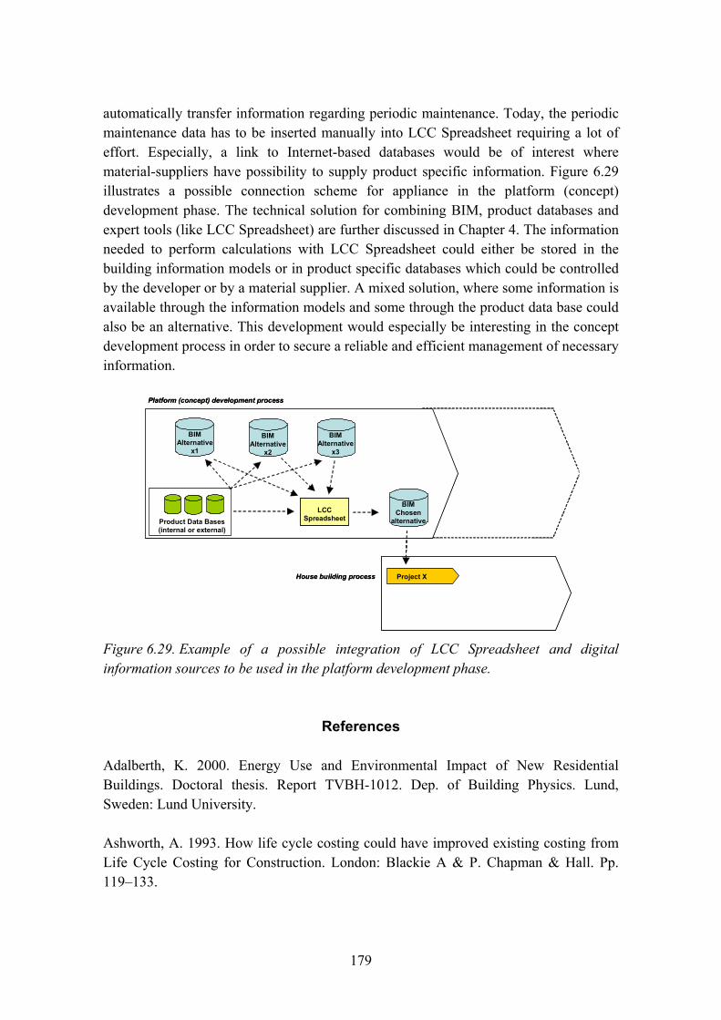
179
automatically transfer information regarding periodic maintenance. Today, the periodic maintenance data has to be inserted manually into LCC Spreadsheet requiring a lot of effort. Especially, a link to Internet-based databases would be of interest where material-suppliers have possibility to supply product specific information. Figure 6.29 illustrates a possible connection scheme for appliance in the platform (concept) development phase. The technical solution for combining BIM, product databases and expert tools (like LCC Spreadsheet) are further discussed in Chapter 4. The information needed to perform calculations with LCC Spreadsheet could either be stored in the building information models or in product specific databases which could be controlled by the developer or by a material supplier. A mixed solution, where some information is available through the information models and some through the product data base could also be an alternative. This development would especially be interesting in the concept development process in order to secure a reliable and efficient management of necessary information.
LCC Spreadsheet
BIM Alternative
x1
Product Data Bases (internal or external)
BIM Alternative
x2
BIM Alternative
x3
Platform (concept) development process
House building process
BIM Chosen
alternative
Project X
LCC Spreadsheet
LCC Spreadsheet
BIM Alternative
x1
Product Data Bases (internal or external)
BIM Alternative
x2
BIM Alternative
x3
Platform (concept) development process
House building process
BIM Chosen
alternative
Project X
Figure 6.29. Example of a possible integration of LCC Spreadsheet and digital information sources to be used in the platform development phase.
References
Adalberth, K. 2000. Energy Use and Environmental Impact of New Residential Buildings. Doctoral thesis. Report TVBH-1012. Dep. of Building Physics. Lund, Sweden: Lund University.
Ashworth, A. 1993. How life cycle costing could have improved existing costing from Life Cycle Costing for Construction. London: Blackie A & P. Chapman & Hall. Pp. 119�133.
180
ASTM. 2000. Standard Practice for Measuring Life-Cycle Costs of Buildings and Building Systems. HISTORICAL STANDARD: E917-99. Annual Book of ASTM Standards, Section four � Construction, Volume 04.11 � Building Constructions.
ASTM. 2006. Standard Practice for Measuring Life-Cycle Costs of Buildings and Building Systems. HISTORICAL STANDARD: E917-99. Internet: http://www.astm.org/cgi-bin/SoftCart.exe/DATABASE.CART/HISTORICAL/E917-99.htm?L+mystore+opwr6296, retrieved 2007-04-20.
DANTES. 2006. EU-financed DANTES project. Internet: http://www.dantes.info/Tools&Methods/Environmentalassessment/enviro_asse_lcc.html, retrieved 2007-04-20.
Industrifakta. 2007. Prisutveckling för flerbostadshus på riksnivå och för enskilda regioner. Rapport, April 2007.
Johansson, C. & Öberg, M. 2001. Life Cycle Costs and Affordability Perspectives for Multi-dwelling Buildings in Sweden. Proceedings of 2nd Nordic Conference on Construction Economics and Organisation, Gothenburg, Sweden. Pp. 287-297.
Kronudd, L. 2007. Beräkning av livscykelkostnader (LCC) i tidiga skeden av konceptbyggande. Diploma work. Div. Building Materials. Lund, Sweden: Lund Technical Institute.
LCAiT. 1996. LCAiT Computer programme for life cycle inventory including eneric environmental databases. Gothenburg, Sweden: Chalmers Industriteknik.
SABO. 2001. Underhållsnorm 2001 (Maintenance guide 2001). (In Swedish.) Stockholm, Sweden: The Swedish Association of Municipal Housing Companies.
SCB. 2005. Bostads- och byggnadsstatistisk årsbok 2005. (In Swedish.) Statistiska Centralbyrån. Örebro: SCB-Tryck.
SCB. 2007. Prisnivån i Sverige 1830�2006 Statistiska Centralbyrån. Internet: http://www.scb.se/templates/tableOrChart____33837.asp, retrieved 2007-04-20.
Steen, B. 1999. A Systematic Approach to Environmental Priority Strategies in Product Development (EPS). Version 2000 � Models and Data of the Default Methods. Stockholm: Center for Environmental Assessment of Products and Material Systems & Technical Environmental Planning.
181
Vold, M. & Rönning, A. 1995. LCA of Cement and Concrete � Main report. Fredrikstad, Norge: Stiftelsen Östfoldsforskning.
Öberg, M. 2005. Integrated Life Cycle Design � Application to Swedish concrete multi-dwelling buildings. Doctoral thesis. Division of Building Materials. Lund, Sweden: Lund University.
6.7 Risks of non-performance in industrialized construction
Lars-Olof Nilsson, Åse Togerö and Carl Jonsson
6.7.1 Abstract
For a selected technical solution of a residential building LCC & LCA are calculated using estimated production costs, estimated component service-life, estimated energy use, estimated maintenance costs, estimated material consumption, etc. Only average values are used and uncertainties or variations are not included. These parameter values are all based on the assumption that the building performance is estimated to fulfil the owner�s and the user�s requirements on thermal comfort, air tightness, indoor air quality, humidity, moisture conditions, noise reduction, etc. However, all these may change if the building�s performance will be far less than expected in the assessments. In industrialized building the possibilities are significant to reduce the uncertainties in full-filling the performance requirements and the variations in the running and maintenance costs. This is, however, not included in traditional LCC-calculations which mean that such important advantages with building platforms are excluded. The paper points out these possibilities, gives some examples and identifies what should be developed to better utilize the advantages of industrialized building.
6.7.2 Introduction
Integrated life-cycle design, ILCD, is a way to include, already in the early design, all relevant aspects of management of a building during its complete service-life (Sarja 2002). Öberg (2005) developed such a design procedure for residential buildings and put together an integrated tool-box that included LCC, LCA, energy balance, thermal comfort, environmental loads, acoustic performance, structural pre-design, concrete drying-times, durability and service-life and fire safety.
182
For a selected technical solution LCC & LCA are calculated using estimated production costs, estimated component service-life, estimated energy use, estimated maintenance costs, estimated material consumption, etc.
Only average values are used and uncertainties or variations are not included. These parameter values are all based on the assumption that the building performance is estimated to fulfil the owner�s and the user�s requirements on thermal comfort, air tightness, indoor air quality, humidity, moisture conditions, noise reduction, etc. However, all these may change if the building�s performance will be far less, or far better, than expected in the assessments.
The probability of this to happen depends on numerous factors such as the selected technical solution or selected design team (i.e. their organization and their competence). Other examples are the construction organisation producing the building, the properties and durability of the selected components and materials, the robustness or vulnerability of the chosen construction technique and the type of control system use during construction.
These aspects should be included into an ILCD, especially in an ILCD for building platforms in industrial construction. If not, some major advantages with platform construction are not fully regarded.
6.7.3 A hypothesis on variations in expected performance in principle
In traditional building processes experience shows a tremendous scatter in the performance of the produced buildings. Figure 6.30 shows the scatter in principle for various cases. The effort put into the design, planning and utilization of experience as feed-back will make the scatter smaller and ensures that the real performance is closer to the intended performance quality in average.

183
Performance
Number of objects
Intendedquality
o SBS, bad healtho visible damages
during constructiono Later damages/problemso Etc
Better design,planning
& feed-back
Performance
Number of objects
Intendedquality
o SBS, bad healtho visible damages
during constructiono Later damages/problemso Etc
Better design,planning
& feed-back
Better design,planning
& feed-back
Figure 6.30. The expected performance of buildings when designed and produced in a traditional building process.
However, in too many cases the performance has been shown to be far too low, in such a way that the building cannot be used at all or used first after significant upgrading has been done. Extreme examples are buildings where the users experience Sick-Building-Syndrome, SBS, or other reasons for bad health because of the building. Buildings are even abandoned in some rare cases for such reasons. More simple examples of bad performance are early cases with visible damages during construction, such as water damages or visible mould growth, or later problems or damages because the technical solutions are badly designed or constructed.
For a �known� or �proved� solution, experience from design, construction and use gives a reasonable probability that it will once again fulfil required performance criteria if used for another building, cf. Figure 6.31. An �acceptable� solution may be one where the probability of fulfilling the requirements is higher than some ¼ to ⅓ and where required upgrading does not cost too much.
To fulfil the performance requirements a certain �margin� must be used between the intended performance quality, that is used as a target in the design phase, and the �expected� quality that corresponds to the performance criteria. The magnitude of this margin depends of course on the client�s requirements and the costs and available time for upgrading those parts of the performance that initially do not fulfil the requirements.
For a �new� solution, where significant experience is lacking, numerous examples have demonstrated that the probability of failure to fulfil the performance criteria is high, cf. Figure 6.31. In these cases the costs for upgrading could be very large and the time required for the works very long.

184
Performance
Number of objects
Intended”expected”quality
�known�
�new�
Performance
Number of objects
Intended”expected”quality
�known��known�
�new��new�
Figure 6.31. The expected variation in performance of buildings when designed and produced in a traditional building process. A �proved� solution compared to a �new� concept.
In both of these cases the �known� or �traditional� and the �new� solution will give life-cycle costs that are far much higher than would be expected if they were estimated beforehand. Figure 6.32 exemplifies the possible benefits that should result from industrial construction using continuously developed building platforms.
Performance
Number of objects
Intended”expected”quality
one, traditional
1st generationplatform
2nd generationplatform
.. and so on!
Performance
Number of objects
Intended”expected”quality
one, traditional
1st generationplatform1st generationplatform
2nd generationplatform2nd generationplatform
.. and so on!
Figure 6.32. The expected variations in performance of buildings when designed and produced in traditional building processes compared to industrialized building.
185
Platform construction utilizes significant resources in design of the 1st generation platforms already. Consequently, the uncertainties/variations should be reduced by platform construction. The extra �costs� in LCC, LCA and low quality, however, are to be multiplied by a large number of �identical� buildings in the 1st generation. Consequently, the total extra costs for already the 2nd generation have much less uncertainties and variations, from follow-up, re-use of experience, etc.). To benefit from that, the variations/uncertainties must be quantified.
6.7.4 Quantification of uncertainties � some examples
LCC-calculations contain a large quantity of parameters that are used to estimate production costs, running and maintenance costs and service-lives. A few examples on the uncertainties of some of these parameters are given and discussed.
Example 1: Energy consumption
A major parameter for running costs during the service-life of a residential building is the energy consumption for heating of the building, the ventilation air, the supplied water etc. Numerous tools are available to predict the energy consumption in such cases. In Figure 6.33 an example is shown for ten very different residential buildings, built by different contractors (Nilsson 2003). The same tool, Enorm, was used to predict the energy consumption for all buildings, resulting in energy consumptions between some 75 and 110 kWh/m2 and year.
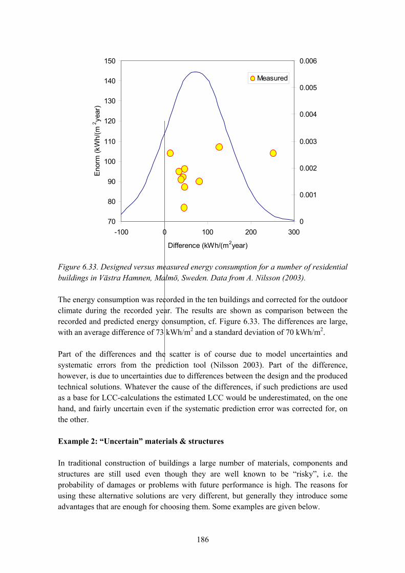
186
70
80
90
100
110
120
130
140
150
-100 0 100 200 300
Difference (kWh/(m2year)
Eno
rm (k
Wh/
(m2 ye
ar)
0
0.001
0.002
0.003
0.004
0.005
0.006
Measured
( )
Figure 6.33. Designed versus measured energy consumption for a number of residential buildings in Västra Hamnen, Malmö, Sweden. Data from A. Nilsson (2003).
The energy consumption was recorded in the ten buildings and corrected for the outdoor climate during the recorded year. The results are shown as comparison between the recorded and predicted energy consumption, cf. Figure 6.33. The differences are large, with an average difference of 73 kWh/m2 and a standard deviation of 70 kWh/m2.
Part of the differences and the scatter is of course due to model uncertainties and systematic errors from the prediction tool (Nilsson 2003). Part of the difference, however, is due to uncertainties due to differences between the design and the produced technical solutions. Whatever the cause of the differences, if such predictions are used as a base for LCC-calculations the estimated LCC would be underestimated, on the one hand, and fairly uncertain even if the systematic prediction error was corrected for, on the other.
Example 2: �Uncertain� materials & structures
In traditional construction of buildings a large number of materials, components and structures are still used even though they are well known to be �risky�, i.e. the probability of damages or problems with future performance is high. The reasons for using these alternative solutions are very different, but generally they introduce some advantages that are enough for choosing them. Some examples are given below.
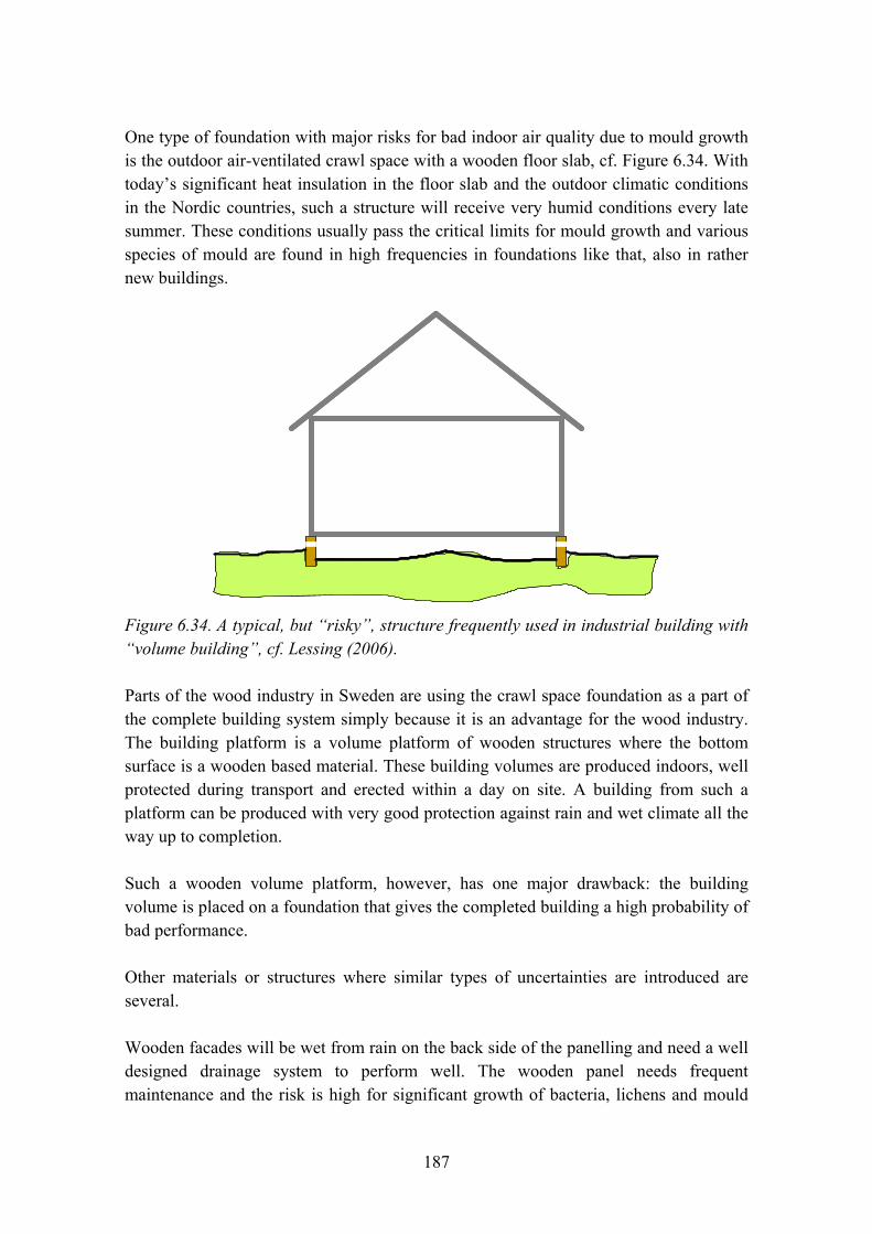
187
One type of foundation with major risks for bad indoor air quality due to mould growth is the outdoor air-ventilated crawl space with a wooden floor slab, cf. Figure 6.34. With today�s significant heat insulation in the floor slab and the outdoor climatic conditions in the Nordic countries, such a structure will receive very humid conditions every late summer. These conditions usually pass the critical limits for mould growth and various species of mould are found in high frequencies in foundations like that, also in rather new buildings.
Figure 6.34. A typical, but �risky�, structure frequently used in industrial building with �volume building�, cf. Lessing (2006).
Parts of the wood industry in Sweden are using the crawl space foundation as a part of the complete building system simply because it is an advantage for the wood industry. The building platform is a volume platform of wooden structures where the bottom surface is a wooden based material. These building volumes are produced indoors, well protected during transport and erected within a day on site. A building from such a platform can be produced with very good protection against rain and wet climate all the way up to completion.
Such a wooden volume platform, however, has one major drawback: the building volume is placed on a foundation that gives the completed building a high probability of bad performance.
Other materials or structures where similar types of uncertainties are introduced are several.
Wooden facades will be wet from rain on the back side of the panelling and need a well designed drainage system to perform well. The wooden panel needs frequent maintenance and the risk is high for significant growth of bacteria, lichens and mould

188
that cause bad visual appearance. Wooden joist floors and wooden roofs experience other types of risks of bad performance and early repair. Other examples are thick concrete floor slabs with long drying times, gypsum boards that are extremely sensitive to moisture, facades with thin plaster on insulation where leakage from driving rain is frequent, flat roofs where the consequences of a small defect in the roofing membrane are significant, etc.
A comparison, in principle, between the expected performance of such �risky� technical solutions with the expected performance from �proven� solutions or solutions from well-developed building platforms is given in Figure 6.35.
Performance
Number of objects
Intended”expected”quality
traditional solutions
1st generationplatform
2nd generationplatform
.. and so on!
�risky� solutionsLCC
Performance
Number of objects
Intended”expected”quality
traditional solutions
1st generationplatform1st generationplatform
2nd generationplatform2nd generationplatform
.. and so on!
�risky� solutionsLCCLCC
Figure 6.35. Expected variation in performance, and LCC, of �risky� solutions compared to traditional and industrial building.
Expressed in terms of service-life the comparison could look like the one in Figure 6.36.
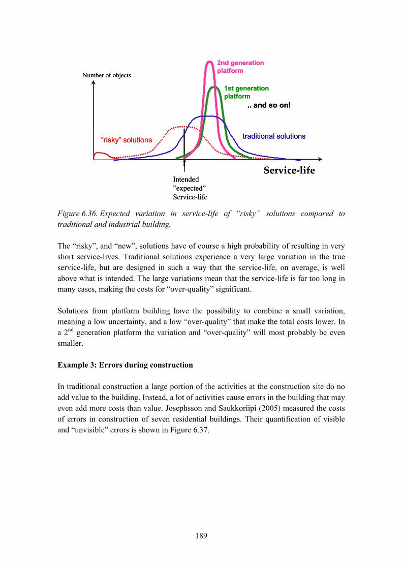
189
Service‐life
Number of objects
Intended”expected”Service-life
traditional solutions
1st generationplatform
2nd generationplatform
.. and so on!
�risky� solutions
Service‐life
Number of objects
Intended”expected”Service-life
traditional solutions
1st generationplatform
2nd generationplatform
.. and so on!
�risky� solutions
Figure 6.36. Expected variation in service-life of �risky� solutions compared to traditional and industrial building.
The �risky�, and �new�, solutions have of course a high probability of resulting in very short service-lives. Traditional solutions experience a very large variation in the true service-life, but are designed in such a way that the service-life, on average, is well above what is intended. The large variations mean that the service-life is far too long in many cases, making the costs for �over-quality� significant.
Solutions from platform building have the possibility to combine a small variation, meaning a low uncertainty, and a low �over-quality� that make the total costs lower. In a 2nd generation platform the variation and �over-quality� will most probably be even smaller.
Example 3: Errors during construction
In traditional construction a large portion of the activities at the construction site do no add value to the building. Instead, a lot of activities cause errors in the building that may even add more costs than value. Josephsson and Saukkoriipi (2005) measured the costs of errors in construction of seven residential buildings. Their quantification of visible and �unvisible� errors is shown in Figure 6.37.
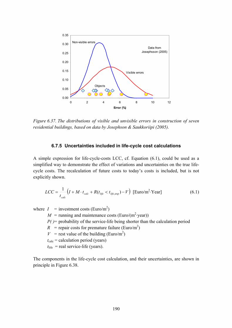
190
0.00
0.05
0.10
0.15
0.20
0.25
0.30
0.35
0 2 4 6 8 10 12
Error (%)
Objects
Visible errors
Non-visible errors
Data fromJosephsson (2005)
Figure 6.37. The distributions of visible and unvisible errors in construction of seven residential buildings, based on data by Josephson & Saukkoriipi (2005).
6.7.5 Uncertainties included in life-cycle cost calculations
A simple expression for life-cycle-costs LCC, cf. Equation (6.1), could be used as a simplified way to demonstrate the effect of variations and uncertainties on the true life-cycle costs. The recalculation of future costs to today�s costs is included, but is not explicitly shown.
( )VttRtMIt
LCC lifelifecalccalc
−<+⋅+= )(1exp, [Euro/m2⋅Year] (6.1)
where I = investment costs (Euro/m2) M = running and maintenance costs (Euro/(m2⋅year)) P( )= probability of the service-life being shorter than the calculation period R = repair costs for premature failure (Euro/m2) V = rest value of the building (Euro/m2) tcalc = calculation period (years) tlife = real service-life (years).
The components in the life-cycle cost calculation, and their uncertainties, are shown in principle in Figure 6.38.
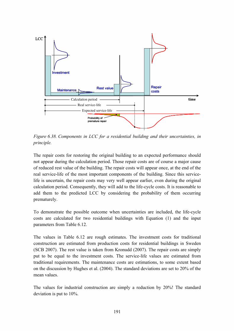
191
time
LCC
Investment
Calculation period
Rest value Repaircosts
Expected service-life
Real service-life
Maintenance
Probability ofpremature repair
time
LCC
Investment
Calculation period
Rest value Repaircosts
Expected service-life
Real service-life
Maintenance
Probability ofpremature repair
Figure 6.38. Components in LCC for a residential building and their uncertainties, in principle.
The repair costs for restoring the original building to an expected performance should not appear during the calculation period. Those repair costs are of course a major cause of reduced rest value of the building. The repair costs will appear once, at the end of the real service-life of the most important components of the building. Since this service-life is uncertain, the repair costs may very well appear earlier, even during the original calculation period. Consequently, they will add to the life-cycle costs. It is reasonable to add them to the predicted LCC by considering the probability of them occurring prematurely.
To demonstrate the possible outcome when uncertainties are included, the life-cycle costs are calculated for two residential buildings with Equation (1) and the input parameters from Table 6.12.
The values in Table 6.12 are rough estimates. The investment costs for traditional construction are estimated from production costs for residential buildings in Sweden (SCB 2007). The rest value is taken from Kronudd (2007). The repair costs are simply put to be equal to the investment costs. The service-life values are estimated from traditional requirements. The maintenance costs are estimations, to some extent based on the discussion by Hughes et al. (2004). The standard deviations are set to 20% of the mean values.
The values for industrial construction are simply a reduction by 20%! The standard deviation is put to 10%.

192
Table 6.12. Estimated input parameter values for a hypothetical LCC-calculation of residential buildings, from a traditional building process and a building platform, respectively.
Traditional Building platform Parameter Dimension
Average Standard deviation Average Standard
deviation Investment kEuro/m2 3000 600 2400 240
Running & maintenance
kEuro/m2year 100 20 80 8
Expected service-life
years 50 10 60 5
Real service-life
years 30 15 60 6
Repair kEuro/m2 3000 600 2400 240
Rest value kEuro/m2 500 100 600 60
All parameters except the expected service-life are assumed to be normal-distributed.
The LCC for the two cases are calculated from Equation (6.1) Monte-Carlo simulation. The results are shown in Figure 6.39.
0.00
0.01
0.02
0.03
0.04
80 100 120 140 160 180 200 220 240 260
LCC [kEuro/(m2year)]
Platform
Traditional
Figure 6.39. Predicted, hypothetical distribution of LCC for a residential building from a traditional building process and an industrial building platform, respectively.

193
Even though this is only a hypothetical example, the predicted results in Figure 6.39 may very well reflect the actual situation. LCC in traditional construction should be higher than platform building and the uncertainty should be larger. More precise data is of course needed to be able to make correct quantifications.
6.7.6 Discussion and conclusions
To be able to develop procedures to consider the probably smaller uncertainties in industrial construction, much better data than is available today is required. Examples of such data are statistics on maintenance costs/economic service-life, damages, bad performance vs. solutions, non-technical issues (user behaviour, surrounding area, etc.). Additionally, new probabilistic tools must be developed for LCC, LCA, service-life, requirements management (e.g. EcoProP) etc.
The full advantages of a building process using a building platform are not included in today�s ILCD-tools. This is of course done in many other industrial sectors, where highly developed industrial processes are common. It is time for the construction sector to use new tools to further demonstrate the benefits of industrial construction for lower LCC and more precise and better performance.
6.7.7 Acknowledgements
The presented work is part of a project funded by the Swedish Council for Environment, Agricultural and Spatial Science, Formas, Tekes � the Finnish Funding Agency for Technology and Innovation, the Swedish Contractors Development Fund, SBUF, and the companies Skanska Sverige AB, Skanska Oyj and Cementa AB.
Ronny Andersson at Cementa provided numerous constructive comments to the initial manuscript. Anne Landin at the division of Construction Management at LTH contributed some ideas on �non-transfer� of experience gained within the building process. Pekka Huovila at VTT provided some references on maintenance costs.
References
Hughes, W. P., Ancell, D., Gruneberg, S. & Hirst, L. 2004. Exposing the myth of the 1:5:200 ratio relating initial cost, maintenance and staffing costs of office buildings. Proceedings of 20th Annual ARCOM Conference, 1�3 September 2004, Edinburgh, UK. Reading: ARCOM. Pp. 373�382.
194
Josephsson, P.-E. & Saukkoriipi, L. 2005. Slöseri i byggprojekt. Behov av förändrat synsätt. Fou-Väst Rapport 0507. Göteborg: Sveriges Byggindustrier.
Kronudd, L. 2007. Beräkning av livscykelkostnader (LCC) i tidiga skeden av konceptbyggande. Diploma work. Div of Building Materials. Lund: Lund Institute of Technology.
Lessing, J. 2006. Industrialised House-Building � Concept and Processes. Licentiate thesis. Department of Design Methodology. Lund: Lund Institute of Technology.
Nilsson, A. 2003. Energianvändning i nybyggda flerbostadshus på Bo01-området i Malmö. Report TVBH-3045. Div. of Building Physics. Lund: Lund Institute of Technology.
Sarja, A. 2002. Integrated Lifecycle Design of Structures. London and New York: Spon Press.
Öberg, M. 2005. Integrated life-cycle design � Application to Swedish concrete multi-dwelling buildings. PhD thesis TVBM-1022. Div of Building Materials. Lund: Lund Institute of Technology.

195
Chapter 7
Contents
7. Summary and conclusions .......................................................................................196 7.1 Summary and conclusions from each chapter ................................................196
7.1.1 The project � objectives and approach...............................................196 7.1.2 Life cycle methodology for buildings � regulatory and
methodological framework ................................................................197 7.1.3 The industrialized building process ...................................................198 7.1.4 Whole-life optimisation of buildings and BIMs ................................199 7.1.5 Toolbox � Methodologies and tools for ILC-D and ILC-C ...............200 7.1.6 Case studies........................................................................................200
7.2 Recommendations for implementation...........................................................205 7.3 Future research and development...................................................................206 References................................................................................................................207
196
7. Summary and conclusions
7.1 Summary and conclusions from each chapter
7.1.1 The project � objectives and approach
The research project �ICT for whole life optimisation of residential buildings� developed and tested the whole life design and optimisation methods for residential buildings. ICTWLORB was performed in cooperation with Swedish and Finnish partners:
− Lund University, project coordinator − VTT Technical Research Centre of Finland − Skanska Sverige AB − Skanska Oyj − Cementa AB.
The objective of the ICTWLORB project was to develop and implement an ICT based toolbox for integrated life cycle design of residential building. The specific objectives of the project were as follows:
− to structure integrated life cycle design methodology for buildings
− to collect and formulate ICT based tools and data bases for requirements management and life cycle design of buildings
− to develop, consolidate and link these tools and data bases in order to form an ICT based toolbox for integrated life cycle design
− to test and implement the toolbox in building projects
− to formulate guidelines for the use of the integrated life cycle design toolbox.
The project presents the integrated life design methodology and individual tools in relation to Building Information Models (BIMs). Product Model based data management in construction projects connects the information needed for design, product manufacturing, construction, commissioning and the use and maintenance of a building. The ICTWLORB project described the role and the place of the usage of individual life cycle design tools in the process of product model based design. The project also suggests performance indicators that should later be considered in the future development of building product model attributes.
The ICTWLORB project defined as a premise that an industrialised building process is characterised by two main elements:

197
− a building concept based approach − efficient information management.
Building concept based approach enables
1) the product development of the end product
2) repetition of the basic elements of the building from one project to others
3) customisation of the end-product considering the specific needs of the case and the client.
Information management enables
1) the consideration of wide spectrum of aspects including building performance, environmental aspects, life cycle costs and service life
2) rapid adapting of the design to the specific requirements of the case.
7.1.2 Life cycle methodology for buildings � regulatory and methodological framework
Chapter 2 discusses the congruence of the life cycle methodologies with the European policy strategies, introduces the regulatory and standardisation framework of life cycle management of buildings, and discusses the availability of methods and tools.
It can be summarised that the adoption of life cycle approach as a basic principle for sustainable building methodologies is consistent with the EU policies on sustainable development. There is also a European process going on, which aims at the development of harmonised life-cycle standards for buildings and building products. The life cycle approach can be distinguished in the two essential directives, which direct the building product and energy regulations of building, namely CPD and EPD; both of these emphasise the importance of use phase of buildings.
Building needs life cycle guides and sustainable construction methods for requirement setting, design for required performance and life-cycle and for declaration of life-cycle quality of final products. An important challenge is that these methods should be able to assess different kinds of systems with help of generally accepted indicators without favouring any specific solutions. In addition, those should be able to support the consideration of user needs and user requirements in building processes.
In order to make construction projects more sustainable it is important to be able to overcome the obstacles of capturing and managing the knowledge needed by project
198
teams to affect such change. There are indicators and assessment tools for sustainability in construction available, but there is still a need for a structured approach for the implementation of sustainability practices and methods within construction projects.
There are many differences between a traditional building process and an industrialised process, and these differences also reflect to the tools needed for the information management. In an industrialised building process the planning and design is mainly carried out as non-unique platforms instead of developing each building project individually with unique choices of technical solutions. Industrialised building processes bring new kinds of needs for information management tools especially with regard to requirement setting. Requirement setting tools should at first support the concept development and finally the customisation of the concepts with the needs and requirements of individual users. However, the use of service life estimation, LCA and LCC tools become easier and more meaningful in an industrialised building process compared to a traditional building process. A long-span development process of building concepts facilitates the use of different kinds of assessment tools and enables the process to seek for optimal alternatives. In addition, the development of databases that are needed in LCAs, service life predictions and care and maintenance directions are meaningful to create and improve, because of the continuous nature of the process.
7.1.3 The industrialized building process
Industrialisation is a lot more than developing type buildings and prefabricated structures. It is much more about optimizing the processes involved in a building project and to identify the best technical solutions. Key factors are:
− repetition − standardisation − system thinking − prefabrication − components − specialisation − logistics.
The industrialized building process includes well-defined concepts for housing, infrastructure, industry or anything else possible in the building sector. An example of a concept for industrialized building process applied to multi-family housing is ModernaHus. Chapter 3 describes the main ingredients in the industrialized building process with examples connected to ModernaHus.
199
To introduce an industrialized building process will turn any organisation, work procedures and traditional methods over. It will have impact not only on each individual in the organisation, but also on the supply chain and consultants.
The industrialized components and technologies are important ingredients, but to reach the beneficial effects, the processes involved in all stages from planning, purchasing, manufacturing and assembly must be penetrated and adjusted, i.e. towards lean planning, lean purchasing, lean manufacturing, lean assembly.
The application of concepts in the building process calls for a change of staff expertise, tools and engineering software. The future should supply:
− Increased use of experts and expert tools for the development of new technical solutions.
− Increased use of scale testing tools, e.g. mock-ups and Monte Carlo simulations.
− Engineering draftsmen with CAD and IT skills and simple �table tools� for the design in the building process. Decreased use of advanced engineering calculations in the building process.
7.1.4 Whole-life optimisation of buildings and BIMs
A Building Information Model contains all project design information, including general arrangement, structure, specification, system components, areas, volumes and all other relevant information, in one single model, well coordinated and in computable mode. The vision of BIM is that all the information produced during the building design process is stored in one model that is independent of any individual use cases. Each individual software used during the building lifecycle can access and update the information, creating an incremental data flow of all the information related to the building design and maintenance process. The vision is compelling since it would eventually solve most of the interoperability problems faced in the construction industry today.
As shown in Chapter 4, Building Information Models enable the linkage of product information and assessment and simulation methods. Building information models provide an effective mean to manage the abundance of information that is needed in integrated life-cycle design.
In an industrialised building process, the owner of the concept represents an actor that has a long running interest in the development and maintaining of all concept-related models, databases and methods. This provides an advantageous situation not only for

200
the development of the concept itself but also for the tools that help information management and integrated design.
7.1.5 Toolbox � Methodologies and tools for ILC-D and ILC-C
Chapter 5 aims at collecting and describing ICT-based tools for life cycle design that are suitable for use in a rational building process and that also eventually could be used in for example Building Information Models or other models suitable for an industrialised building process.
There are many tools that could be brought up, but the purpose of the subproject in ICTWLORB has not been to find the best available tools, as this demands a very complex and time consuming valuation process, with risks of choices eventually made on biased opinions in any case. Instead the project group has focused on collecting a series of tools which are well suitable and functional for the purposes mentioned earlier, and of which the project members have good knowledge and experience.
The tools that are recommended to use during the different phases, are shown in tables, for each of the three processes � the traditional building process, the industrialised process with two steps: ILC Design in the development of concepts, and ILC Customisation/Configuration in the building project process.
Some of the tools are described in more detail, as they represent good examples of tools to use in an ILC process. The described tools are listed in alphabetical order in a format that makes it easy to compare them and that facilitates eventual listing in a database. The form contains the name, purpose, intended user, functions, inputs, outputs, access, sources and user rights.
7.1.6 Case studies
Chapter 6 describes the experiences from testing selected tools for whole life optimization of residential buildings.
EcoProp/ModernaHus
EcoProP is mainly used by (or together with) developers (owners, project management consultants) in collaboration with the design team before technical solutions for construction are chosen. The objective is to capture and maintain customer requirements in the process in order to achieve solutions that meet customer needs and add value to
201
owners and end users. This was tested on the building platform of Skanska ModernaHus.
EcoProP can be helpful when applying on project but it is more difficult when it is applied to development of a concept. When applying the concept on a project, a lot of requirements are already set from the concept but when developing a concept there is less in-data from where the initial requirements are set. When developing a concept it is much based on market surveys and experience.
It would be helpful with a tool to help set the initial requirements, set the predefined levels and not just making sure that they are line up and that the decided requirements are followed. When the user chooses the levels themselves, how do they get the information on what levels to set when it is not a local authority regulation or similar? A tool could be required to help make decisions about the initial requirements so that the bar is not set too low or too high because of lack of understanding.
Service-life tools for concrete structures
The service life of materials, components, structures and systems is essential to know for several reasons in ILCD. The service-life is a significant input to mainly LCC and LCA. For most materials and components the service-life is found from experience and provided by the suppliers and included in ICT-tools like LifePlan or by user organisations like SABO and included in databases in LCC-tools (Öberg 2005).
For concrete structures, however, the variety of material qualities and exposure conditions is huge and calculation tools are needed. Here a few tools are presented.
The service-life calculation tool Ennus Concrete is extremely simple to use and it seems to reflect the Finnish concrete code BY-50 in an excellent way. The code BY-50, however, seems strange in many parts and the principle of the factor method can be questioned, with a large number of factors being treated as independent factors.
The DuraCrete framework offers a strong tool for performance based durability design. Models and test methods are available for predictions of environmental actions based on local climatic data and for service-life of concrete structures. Data is available for European conditions, but mainly for reinforcement corrosion. For frost a lot of data is still missing.
202
LifePlan/Ecometer
Skanska Oyj�s Ecometer is a web-based calculation tool intended for assessing the environmental attributes of residential projects. It is used to assess the energy consumption and ecological profile of a building during its life cycle from construction through the use and maintenance phases.
LifePlan is a product-specific data base for service life information of building products and components.
As a part of the ICTWLORB project, Skanska Oyj began development work for reducing the amount of manual work required to carry out an Ecometer calculation. The overall aim was to make an automated link between Ecometer and the LifePlan files so that the environmental profiles of different production materials and products enter the calculation automatically. This reduces the time needed for the designer to include all the relevant parameters into an assessment and is expected to increase Ecometer�s value and usability in making various comparisons of possible design solutions. The system will also provide the possibility to further develop Ecometer to use other LifePlan information, which then provides possibilities to increase the scope and detail of Ecometer calculations and reports.
To use environmental profiles from the LifePlan database as a source for the Ecometer tool, the interface between the LifePlan LCA data and the Skanska Ekometer is still needed. This work in Skanska Oyj is underway and could not be finished within the ICTWLORB project.
LifePlan/ModernaHus
The LifePlan database is a Web-based system and the output is in XML description language which enables to make automatic arrangements later on in order to include the information in the users/designers own systems which help them to perform service life design. This information could also be linked in design phase with CAD-systems. For the case study, VTT introduced the LifePlan concept and translated the LifePlan cover page and framework into English.
The main purpose of the case study was to enable the collection of care and maintenance information of building products from different suppliers in order to build a building concept specific-database. In the ICTWLORB-project it was agreed that Skanska Sweden will arrange the product Service Life data collection for their building concept called ModernaHus. After the case trial Skanska�s ModernaHus LifePlan database was built up for the products like facade elements + joints, balconies, roofs (steel + bitumen), windows, entrance canopy and air intake below windows.

203
With the help of LifePlan database it is possible to collect building material service life, care and maintenance data for substantial number of building materials. The system helps to manage large amount of data and use it in an intelligent way. In this case study the amount of building materials dealt with was very small and because of that this benefit was not achieved. However, the exercise was useful because it was possible to point out some unpractical operation of the tool (the main problems appeared because of system sensitivity).
Experiences of applying LCC Spreadsheet to ModernaHus
The main focus in the case study has been on evaluating the applicability of the IT-tool LCC Spreadsheet and the needed lifecycle cost information. The test of LCC Spreadsheet has been carried out by two diploma workers and a more detailed description of the work is available in a diploma thesis (Kronudd 2007). The LCC Spreadsheet has been tested on Skanska�s ModernaHus which is a concept for industrialized building process applied to multi-family buildings.
LCC Spreadsheet contains all important cost items in order to perform a reliable LCC calculation. However, this kind of information is not always easy accessible and more generalized information has to be used resulting in less reliable results.
The simplified LCA-method included in LCC Spreadsheet is limited to the energy use of a building�s lifecycle and therefore underestimates the real environmental impact. At present, the ILCD Toolbox includes a full LCA method on a concrete building frame covering all important environmental stressors. The full LCA is based on the generic LCAiT tool and can be expanded to include any other type of material or component that is incorporated into the building. Consequently, one interesting idea would be to enlarge the LCAiT-module in order to cover materials and building components which are used in the ModernaHus-concept. However it should be noted that a crucial aspect is that complete, robust and reliable quantitative environmental data for building products are only available for a limited number of products and materials.
Furthermore, a complete LCA method also requires a significant increase of detailed information implying more effort in gathering data and performing necessary calculations. When it comes to other input information needed in LCC Spreadsheet, there are different possible improvements. One preferable option is to create some kind of database covering needed information about municipals and bigger cities. For this purpose, the sources used in the case study would be preferable to use as a basis. The information should also include specific data on price levels concerning electricity and district heating for each municipal and city.

204
Concerning the general kind of information needed in LCC Spreadsheet, an interesting improvement would be to have a functionality which enables a quick and easily change of geographic dependent parameters such as cots for administration, caretaking, water and sewage, electricity, district heating, waste disposal and insurance. When knowing the location of the building this kind of information would be generated automatic by the programme.
Risks of non-performance in industrialized construction
For a selected technical solution of a residential building LCC & LCA are calculated using estimated production costs, estimated component service-life, estimated energy use, estimated maintenance costs, estimated material consumption, etc. Only average values are used and uncertainties or variations are not included. These parameter values are all based on the assumption that the building performance is estimated to fulfil the owner�s and the user�s requirements on thermal comfort, air tightness, indoor air quality, humidity, moisture conditions, noise reduction, etc. However, all these may change if the building�s performance will be far less than expected in the assessments. In industrialized building the possibilities are significant to reduce the uncertainties in full-filling the performance requirements and the variations in the running and maintenance costs. This is, however, not included in traditional LCC-calculations which mean that such important advantages with building platforms are excluded.
These possibilities are pointed out, some examples are given and what should be developed to better utilize the advantages of industrialized building is identified. A hypothetical example is used to simulate the effects, see Figure 7.1.
To be able to develop procedures to consider the probably smaller uncertainties in industrial construction, much better data than is available today is required. Examples of such data are statistics on maintenance costs/economic service-life, damages, bad performance vs. solutions, non-technical issues (user behaviour, surrounding area, etc.). Additionally, new probabilistic tools must be developed for LCC, LCA, service-life, requirements management (e.g. EcoProP) etc.
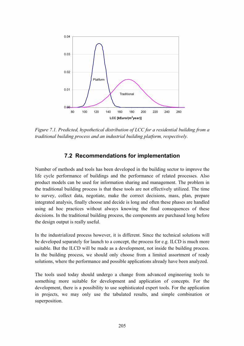
205
0.00
0.01
0.02
0.03
0.04
80 100 120 140 160 180 200 220 240 260
LCC [kEuro/(m2year)]
Platform
Traditional
Figure 7.1. Predicted, hypothetical distribution of LCC for a residential building from a traditional building process and an industrial building platform, respectively.
7.2 Recommendations for implementation
Number of methods and tools has been developed in the building sector to improve the life cycle performance of buildings and the performance of related processes. Also product models can be used for information sharing and management. The problem in the traditional building process is that these tools are not effectively utilized. The time to survey, collect data, negotiate, make the correct decisions, mass, plan, prepare integrated analysis, finally choose and decide is long and often these phases are handled using ad hoc practices without always knowing the final consequences of these decisions. In the traditional building process, the components are purchased long before the design output is really useful.
In the industrialized process however, it is different. Since the technical solutions will be developed separately for launch to a concept, the process for e.g. ILCD is much more suitable. But the ILCD will be made as a development, not inside the building process. In the building process, we should only choose from a limited assortment of ready solutions, where the performance and possible applications already have been analyzed.
The tools used today should undergo a change from advanced engineering tools to something more suitable for development and application of concepts. For the development, there is a possibility to use sophisticated expert tools. For the application in projects, we may only use the tabulated results, and simple combination or superposition.
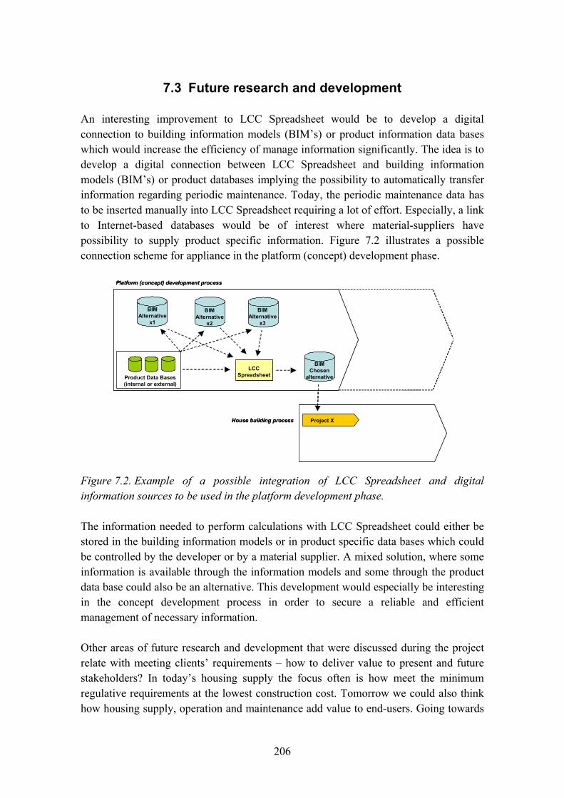
206
7.3 Future research and development
An interesting improvement to LCC Spreadsheet would be to develop a digital connection to building information models (BIM�s) or product information data bases which would increase the efficiency of manage information significantly. The idea is to develop a digital connection between LCC Spreadsheet and building information models (BIM�s) or product databases implying the possibility to automatically transfer information regarding periodic maintenance. Today, the periodic maintenance data has to be inserted manually into LCC Spreadsheet requiring a lot of effort. Especially, a link to Internet-based databases would be of interest where material-suppliers have possibility to supply product specific information. Figure 7.2 illustrates a possible connection scheme for appliance in the platform (concept) development phase.
LCC Spreadsheet
BIM Alternative
x1
Product Data Bases (internal or external)
BIM Alternative
x2
BIM Alternative
x3
Platform (concept) development process
House building process
BIM Chosen
alternative
Project X
LCC Spreadsheet
LCC Spreadsheet
BIM Alternative
x1
Product Data Bases (internal or external)
BIM Alternative
x2
BIM Alternative
x3
Platform (concept) development process
House building process
BIM Chosen
alternative
Project X
Figure 7.2. Example of a possible integration of LCC Spreadsheet and digital information sources to be used in the platform development phase.
The information needed to perform calculations with LCC Spreadsheet could either be stored in the building information models or in product specific data bases which could be controlled by the developer or by a material supplier. A mixed solution, where some information is available through the information models and some through the product data base could also be an alternative. This development would especially be interesting in the concept development process in order to secure a reliable and efficient management of necessary information.
Other areas of future research and development that were discussed during the project relate with meeting clients� requirements � how to deliver value to present and future stakeholders? In today�s housing supply the focus often is how meet the minimum regulative requirements at the lowest construction cost. Tomorrow we could also think how housing supply, operation and maintenance add value to end-users. Going towards

207
this direction would require understanding better what customers� needs really are, and building the capability of providing such services. Industrialized processes, customized to different market segments seem to provide a good prerequisite for that. What is still missing is the requirement model preceding the design model, and sustainable business models supporting successful branding, market differentiation and whole life services.
References
Kronudd, L. 2007. Beräkning av livscykelkostnader (LCC) i tidiga skeden av konceptbyggande. Diploma work. Div. Building Materials. Lund, Sweden: Lund Technical Institute.
Öberg, M. 2005. Integrated life-cycle design in residential buildings. PhD thesis. Div. of Building Materials. Lund: Lund Institute of Technology.

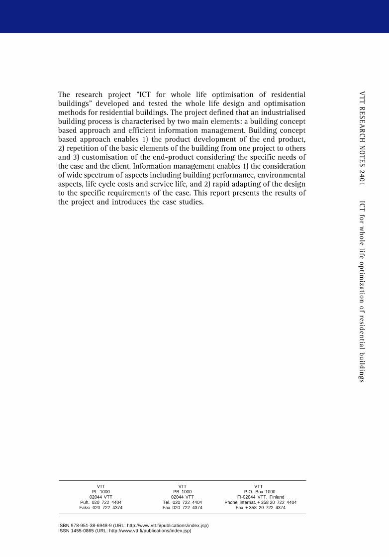
VTT R
ESEAR
CH
NO
TES 2401 ICT for w
hole life optimization of residential buildings
ESPOO 2007 VTT RESEARCH NOTES 2401
The research project "ICT for whole life optimisation of residentialbuildings" developed and tested the whole life design and optimisationmethods for residential buildings. The project defined that an industrialisedbuilding process is characterised by two main elements: a building conceptbased approach and efficient information management. Building conceptbased approach enables 1) the product development of the end product,2) repetition of the basic elements of the building from one project to othersand 3) customisation of the end-product considering the specific needs ofthe case and the client. Information management enables 1) the considerationof wide spectrum of aspects including building performance, environmentalaspects, life cycle costs and service life, and 2) rapid adapting of the designto the specific requirements of the case. This report presents the results ofthe project and introduces the case studies.
Tarja Häkkinen, Sirje Vares, Pekka Huovila,Erkki Vesikari, Janne Porkka, Lars-Olof Nilsson,Åse Togerö, Carl Jonsson, Katarina Suber,Ronny Andersson, Robert Larsson & Isto Nuorkivi
ICT for whole life optimization ofresidential buildings
ISBN 978-951-38-6948-9 (URL: http://www.vtt.fi/publications/index.jsp)ISSN 1455-0865 (URL: http://www.vtt.fi/publications/index.jsp)
SkanskaModerna Hus
Concept
ILCD
Toolbox
EKOMETER
LifePlan
Ennus-ConcreteSuppliers
data
SABO(experience
data)
DatabaseComparison
InterfaceDatabase
Maintenance Plan Data LCC
LCA
Maintenance Plan Data
Interface
Ennus-Wood
Ennus-Steel
EcoProPSkanska
Moderna Hus Concept
ILCD
Toolbox
EKOMETER
LifePlan
Ennus-ConcreteSuppliers
data
SABO(experience
data)
DatabaseComparison
InterfaceDatabase
Maintenance Plan Data LCC
LCA
Maintenance Plan Data
Interface
Ennus-Wood
Ennus-Steel
EcoProP
VTT VTT VTTPL 1000 PB 1000 P.O. Box 1000
02044 VTT 02044 VTT FI-02044 VTT, FinlandPuh. 020 722 4404 Tel. 020 722 4404 Phone internat. + 358 20 722 4404Faksi 020 722 4374 Fax 020 722 4374 Fax + 358 20 722 4374

Series title, number and report code of publication
VTT Research Notes 2401 VTT-TIED-2401
Author(s) Häkkinen, Tarja, Vares, Sirje, Huovila, Pekka, Vesikari, Erkki, Porkka, Janne, Nilsson, Lars-Olof, Togerö, Åse, Jonsson, Carl, Suber, Katarina, Andersson, Ronny, Larsson, Robert & Nuorkivi, Isto Title ICT for whole life optimisation of residential buildings
Abstract The research project �ICT for whole life optimisation of residential buildings� (ICTWLORB) developed and tested the whole life design and optimisation methods for residential buildings. The objective of the ICTWLORB project was to develop and implement an ICT based tool box for integrated life cycle design of residential building. ICTWLORB was performed in cooperation with Swedish and Finnish partners. The ICTWLORB project defined as a premise that an industrialised building process is characterised by two main elements: a building concept based approach and efficient information management. Building concept based approach enables 1) the product development of the end product, 2) repetition of the basic elements of the building from one project to others and 3) customisation of the end-product considering the specific needs of the case and the client. Information management enables 1) the consideration of wide spectrum of aspects including building performance, environmental aspects, life cycle costs and service life, and 2) rapid adapting of the design to the specific requirements of the case.
ISBN 978-951-38-6948-9 (URL: http://www.vtt.fi/publications/index.jsp)
Series title and ISSN Project number VTT Tiedotteita � Research Notes 1455-0865 (URL: http://www.vtt.fi/publications/index.jsp)
1157
Date Language Pages August 2007 English 207 p.
Name of project Commissioned by ICT for whole life optimisation of residential buildings
Tekes � Finnish Funding Agency for Technology and Innovation, FORMAS, participating organisations
Keywords Publisher life cycle, integrated, buildings, design, industrialised
VTT Technical Research Centre of Finland P.O. Box 1000, FI-02044 VTT, Finland Phone internat. +358 20 722 4404 Fax +358 20 722 4374


![Basics of colour & lightness 9.10.2014 / Tarja Peromaa PsyL Tarja Peromaa [tarja.peromaa@helsinki.fi] University of Helsinki Department of Behavioral Sciences.](https://static.fdocuments.us/doc/165x107/56649d0e5503460f949e3b17/basics-of-colour-lightness-9102014-tarja-peromaa-psyl-tarja-peromaa-tarjaperomaahelsinkifi.jpg)


