Especificaciones Chiller
102
FORM 150.67-EG1 (713) Model YCAL Air-Cooled Scroll Compressor Liquid Chillers Style E 50 and 60Hz 15 – 65 TON 53 – 218 kW R-410A
description
especificaciones tecnicas de un chiller enfriado por agua
Transcript of Especificaciones Chiller
FORM 150.67-EG1 (713)
Model YCAL Air-Cooled Scroll Compressor Liquid ChillersStyle E
50 and 60Hz15 – 65 TON53 – 218 kW
R-410A
2
FORM 150.67-EG1 (713)
JOHNSON CONTROLS
FORM 150.67-EG1 (713) ....................................................................................................................................................................................... 1Introduction ........................................................................................................................................................................................................... 3Specification ......................................................................................................................................................................................................... 4MicroComputer Control Center ........................................................................................................................................................................... 5Options and Accessories .................................................................................................................................................................................... 7Unit Nomenclature .............................................................................................................................................................................................. 10Selection Data ......................................................................................................................................................................................................11Selection Data - cont. ......................................................................................................................................................................................... 12Design Parameters ............................................................................................................................................................................................. 13Water Pressure Drop .......................................................................................................................................................................................... 14Ratings - R-410A (60Hz - English Units) ........................................................................................................................................................... 16Ratings - R-410A (60Hz - SI Units) .................................................................................................................................................................... 22Ratings - R-410A (50Hz - English Units) ........................................................................................................................................................... 26Ratings - R-410A (50Hz - SI Units) .................................................................................................................................................................... 32Part Load Ratings - 60 Hz R-410A (English Units) .......................................................................................................................................... 36Part Load Ratings - 50 Hz R-410A (English Units) .......................................................................................................................................... 37Physical Data - English & SI .............................................................................................................................................................................. 38Dimensions - YCAL0019 (English) .................................................................................................................................................................... 40Dimensions - YCAL0022 (English) .................................................................................................................................................................... 42Dimensions - YCAL0028 (English) .................................................................................................................................................................... 44Dimensions - YCAL0033 (English) .................................................................................................................................................................... 46Dimensions - YCAL0043 (English) .................................................................................................................................................................... 48Dimensions - YCAL0046 (English) .................................................................................................................................................................... 50Dimensions - YCAL0052 (English) .................................................................................................................................................................... 52Dimensions - YCAL0056 (English) .................................................................................................................................................................... 54Dimensions - YCAL0066 (English) .................................................................................................................................................................... 56Dimensions - YCAL0019 (SI) ............................................................................................................................................................................. 58Dimensions - YCAL0022 (SI) ............................................................................................................................................................................. 60Dimensions - YCAL0028 (SI) ............................................................................................................................................................................. 62Dimensions - YCAL0033 (SI) ............................................................................................................................................................................. 64Dimensions - YCAL0043 (SI) ............................................................................................................................................................................. 66Dimensions - YCAL0046 (SI) ............................................................................................................................................................................. 68Dimensions - YCAL0052 (SI) ............................................................................................................................................................................. 70Dimensions - YCAL0056 (SI) ............................................................................................................................................................................. 72Dimensions - YCAL0066 (SI) ............................................................................................................................................................................. 74Isolator Selections.............................................................................................................................................................................................. 76Electrical Data - 50 & 60Hz................................................................................................................................................................................. 80Electrical Notes................................................................................................................................................................................................... 82Circuit Breaker Calculations ............................................................................................................................................................................. 84Power Wiring - Single Circuit ............................................................................................................................................................................ 85Power Wiring - Dual Circuit ............................................................................................................................................................................... 89Control Wiring ..................................................................................................................................................................................................... 93Application Data ................................................................................................................................................................................................. 94Guide Specifications .......................................................................................................................................................................................... 96
Table of Contents
Products are produced at af ac i l i t y whose qua l i t y -management systems areISO9001 certified.
PERFORMANCE DATA PROVIDED IN THIS DOCUMENT WAS CREATED IN ACCORDANCE WITH JOHNSON CONTROLS SOFT-WARE: YORKWORKS VERSION 13.02 AND DXCHILL VERSION 6.04
JOHNSON CONTROLS 3
FORM 150.67-EG1 (713)
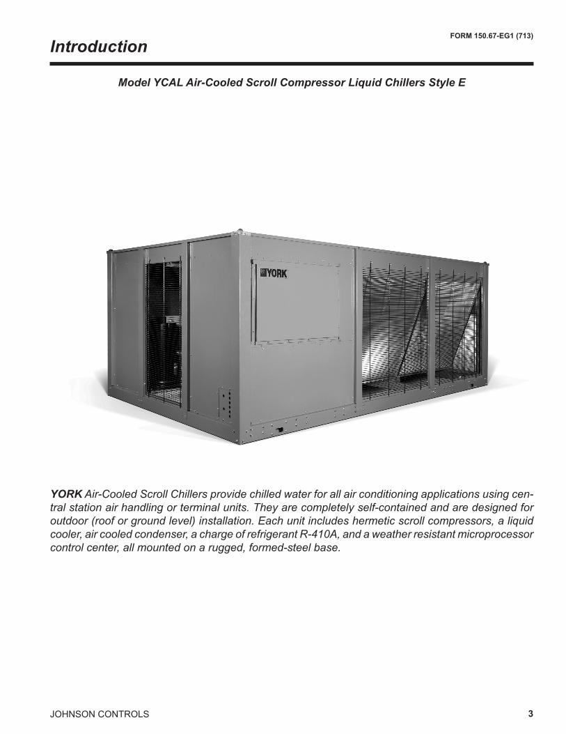
YORK Air-Cooled Scroll Chillers provide chilled water for all air conditioning applications using cen-tral station air handling or terminal units. They are completely self-contained and are designed for outdoor (roof or ground level) installation. Each unit includes hermetic scroll compressors, a liquid cooler, air cooled condenser, a charge of refrigerant R-410A, and a weather resistant microprocessor control center, all mounted on a rugged, formed-steel base.
Introduction
Model YCAL Air-Cooled Scroll Compressor Liquid Chillers Style E
4
FORM 150.67-EG1 (713)
JOHNSON CONTROLS
Specification
GENERALThe 15 - 65 Ton (53 - 218 kW) YCAL models are shipped complete from the factory ready for installation and use.
The unit is pressure-tested, evacuated, and fully charged with Refrigerant-410A and includes an initial oil charge. After assembly, a complete operational test is performed with water flowing through the cooler to assure that the refrigeration circuit operates correctly.
The unit structure is heavy-gauge, galvanized steel. The steel is coated with baked-on powder paint, which, when subjected to ASTM B117 1000 hour, salt spray testing, yields a minimum ASTM 1654 rating of “6”. Corrosion resistant wire mesh panels are added to protect the con-denser coil from incidental damage and restrict unauthor-ized access to internal components. Unit also includes service isolation valves as standard. Units are designed in accordance with NFPA 70 (National Electric Code), ASHRAE/ANSI 15 Safety code for mechanical refrig-eration, ASME, Listed and labeled with Intertek Test-ing Services (ETL) and rated in accordance with the latest version of ARI Standard 550/590.
COMPRESSORSThe chiller has suction-gas cooled, hermetic, scroll com-pressors. The compressors incorporate a scroll design that is compliant in both the axial and radial direction. All rotating parts are statically and dynamically balanced. A large internal volume and oil reservoir provides greater liquid tolerance. Compressor crankcase heaters are also included for extra protection against liquid migration.
COOLERBrazed plate heat exchangers are UL (Underwriters Laboratories) listed. Installing contractor must include ac-
commodations in the chilled water piping to allow proper drainage and venting of the heat exchanger. Water inlet and outlet connections are grooved for compatibility with factory supplied ANSI/AWWA C-606 connections.
The cooler is equipped with a heater controlled by a sepa-rate thermostat. The heater provides freeze protection for the cooler down to -20°F (-29°C) ambient. The cooler is covered with 3/4” (19mm) flexible, closed-cell, foam insulation (K≈0.25).
A 40 mesh strainer (0.5 and 1.5 mm) is recommended upstream of the heat exchanger to prevent clogging.
CONDENSERCoils – Fin and tube condenser coils of seamless, inter-nally-enhanced, high-condensing-coefficient, corrosion resistant copper tubes are arranged in staggered rows, mechanically expanded into aluminum fins. Integral subcooling is included. The design working pressure of the coil is 650 PSIG (45 barg).
Low Sound Fans – The condenser fans are composed of corrosion resistant aluminum hub and composite blades molded into a low noise airfoil section. They are designed for maximum efficiency and are statically and dynamically balanced for vibration-free operation. They are directly driven, and positioned for vertical air discharge. The fan guards are constructed of heavy-gauge, rust-resistant, PVC (polyvinyl chloride)-coated steel wire.
Motors – The fan motors are Totally Enclosed Air-Over, squirrel-cage type, current protected. They feature ball bearings that are double-sealed and permanently lubri-cated.
JOHNSON CONTROLS 5
FORM 150.67-EG1 (713)
All controls are contained in a NEMA 3R powder painted steel cabinet with a gasketed door and include:
Liquid Crystal Display (LCD) with Light Emitting Diode (LED) backlighting for outdoor viewing: Two display lines Twenty characters per line
Color coded 12-button non-tactile keypad with sections for: DISPLAY/PRINT of typical information: Chilled liquid temperatures Ambient temperature System pressures (each circuit) Operating hours and starts (each compressor) Print calls up to the liquid crystal display: Operating data for the systems History of fault shutdown data for up to the last six fault
shutdown conditions
An RS-232 port, in conjunction with this press-to-print button, is provided to permit the capability of hard copy print-outs via a separate printer (by others).
ENTRY section to: ENTER setpoints or modify system values
SETPOINTS updating can be performed to: Chilled liquid temperature setpoint and range Remote reset temperature range Set daily schedule/holiday for start/stop Manual override for servicing Low and high ambient cutouts Number of compressors Low liquid temperature cutout Low suction pressure cutout High discharge pressure cutout Anti-recycle timer (compressor start cycle time) Anti-coincident timer (delay compressor starts)
UNIT section to: Set time Set unit options
UNIT ON/OFF switchThe microprocessor control center is capable of display-ing the following: • Return and leaving liquid temperature • Low leaving liquid temperature cutout setting • Low ambient temperature cutout setting • Outdoor air temperature • English or Metric data • Suction pressure cutout setting • Each system suction pressure • Discharge pressure (optional) • Liquid Temperature Reset via a Johnson Controls ISN
DDC or Building Automation System (by others) via:- a pulse width modulated (PWM) input as stan-
dard- a 4-20 milliamp or 0 -10 VDC input, or contact
closure with the optional B.A.S. interface option • Anti-recycle timer status for each system • Anti-coincident system start timer condition • Compressor run status • No cooling load condition • Day, date and time • Daily start/stop times • Holiday status • Automatic or manual system lead/lag control • Lead system definition • Compressor starts & operating hours (each compressor) • Status of hot gas valves, evaporator heater and fan
operation • Run permissive status • Number of compressors running • Liquid solenoid valve status • Load & unload timer status • Water pump status
* Intensity of Protection European Standard
MicroComputer Control Center
6
FORM 150.67-EG1 (713)
JOHNSON CONTROLS
The panel has provisions for: pumpdown at shutdown; optional remote chilled water temperature reset and two steps of demand load limiting from an external building automation system. Unit alarm contacts are standard.
The operating program is stored in non-volatile memory (EPROM) to eliminate chiller failure due to AC powered failure/battery discharge. Programmed setpoints are re-tained in lithium battery-backed RTC memory for 5 years minimum.
COMMUNICATIONS• Native communication capability for BACnet (MS/TP),
Modbus and N2• Optional communciation available for LON via eLink
option
POWER PANEL
Each panel contains: • Compressor power terminals • Compressor motor starting contactors per l.E.C.** • Control power terminals to accept incoming for 115-1-60 control power • Fan contactors & overload current protection
The power wiring is fully contained inside the unit and secured in place.
** International Electrotechnical Commission
MicroComputer Control Center - continued
JOHNSON CONTROLS 7
FORM 150.67-EG1 (713)
Options and Accessories
ELECTRICAL OPTIONS
SINGLE-POINT SUPPLY TERMINAL BLOCK – Stan-dard. Includes enclosure, terminal-block and intercon-necting wiring to the compressors. Separate external protection must be supplied, by others, in the incoming compressor-power wiring. (Do not include this option if either the SinglePoint NonFused Disconnect Switch or Single-Point Circuit Breaker options have been included.)
SINGLE-POINT NON-FUSED DISCONNECT SWITCH – Unit-mounted disconnect switch with external, lockable handle (in compliance with Article 440-14 of N.E.C.), can be supplied to isolate the unit power voltage for servicing. Separate external fusing must be supplied, by others in the power wiring, which must comply with the National Electrical Code and/or local codes.
SINGLE-POINT CIRCUIT BREAKER – A unit mounted circuit breaker with external, lockable handle (in compli-ance with N.E.C. Article 440-14), can be supplied to isolate the power voltage for servicing. (This option includes the Single-Point Power connection.)
CONTROL TRANSFORMER – Converts unit power voltage to 115-1-60 or 115-1-50 if 50Hz is selected (0.5 or 1.0 KVA capacity). Factory mounting includes primary and secondary wiring between the transformer and the control panel. (Factory-mounted.)
POWER FACTOR CORRECTION CAPACITORS – Will correct unit compressor power factors to 0.90-0.95. (Factory-mounted.)
CONTROL OPTIONS
AMBIENT KIT (LOW) – Standard units will operate to 25°F (-4°C). This accessory includes all necessary components to permit chiller operation to 0°F (-18°C). (This option includes the Discharge Pressure Transducer/Readout Capability option.) For proper head pressure control in applications below 25°F (-4°C), where wind gusts may exceed five mph, it is recommended that Optional Con-denser Louvered Enclosure Panels also be included. (Factory-mounted.)
AMBIENT KIT (HIGH) – Required if units are to operate when the ambient temperature is above 110°F (43°C). Includes discharge pressure transducers. (This option includes the Discharge Pressure Transducer / Readout-Capability option.) (Field-Mounted.)
LANGUAGE LCD AND KEYPAD DISPLAY – Spanish, French, and German unit LCD controls and keypad display available. Standard language is English.
DISCHARGE PRESSURE TRANSDUCERS AND READ-OUT CAPABILITY – The addition of pressure transducers allows models to sense and display discharge pressure. This is recommended for glycol chilling applications. (This option is included with either the low or high ambient kits.) (Factory-mounted.)
SUCTION PRESSURE TRANSDUCERS – Permits unit to sense and display suction pressure. This capability is standard. MOTOR CURRENT MODULE – Capable of monitoring compressor motor current. Provides extra protection against compressor reverse rotation, phase-loss and phase imbalance. Option consists of one module per electrical system. (Factory-mounted.)
COMPRESSOR, PIPING, EVAPORATOR OP-TIONS
LOW TEMPERATURE GLYCOL – Required for glycol chilling below 30°F (-1°C) leaving glycol temperature. Op-tion includes resized thermal expansion valve. (Factory-mounted.)
CHICAGO CODE RELIEF VALVES – Unit will be provided with relief valves to meet Chicago code requirements. (Factory-mounted.)
SERVICE ISOLATION VALVE – Service isolation valves are standard to unit. This includes a system high pressure relief valve or internal compressor relief mechanism in compliance with ASHRAE 15. (Factory-mounted.)
HOT GAS BY-PASS – Permits continuous, stable opera-tion at capacities below the minimum step of compressor unloading to as low as 5% capacity (depending on both the unit and operating conditions) by introducing an arti-ficial load on the cooler. Hot gas by-pass is installed on only refrigerant system #1 on two-circuit units. (Factory-mounted.)
DX COOLER 300 PSIG (21 BARG) DWP WATERSIDE – The waterside will be rated to 300 PSIG (21 barg) instead of the standard 150 PSIG DWP. 300 PSIG R.F. flanges are included on the DX cooler nozzles. The companion flanges will be field-supplied by others. (Factory-mounted.)
FLANGES (ANSI/AWWA C-606 COUPLINGS TYPE) – Consists of two (2) Flange adapters for grooved end pipe (standard 150 psi [10.5 barg] cooler).
FLOW SWITCH – The flow switch or its equivalent must be furnished with each unit.
8
FORM 150.67-EG1 (713)
JOHNSON CONTROLS
• 150PSIG(10.5BARG)DWP– For standard units. Johnson Controls model F61MG-1C vaporproof SPDT, NEMA 4X switch (150 PSIG [10.5 barg] DWP), -20°F to 250°F (-29°C to 121°C), with 1” NPT connection for upright mounting in horizontal pipe. (Field-mounted.)
• 300PSIG(21BARG)DWP–For units with optional 300 PSIG (21 barg) DX cooler. McDonnell & Miller model FS74W vaporproof SPDT, NEMA 4X switch (300 PSIG (21 barg) DWP), -20°F to 300°F (-29°C to 149°C), with 1¼ inch MPT connection for upright mounting in horizontal pipe. (Field-mounted.)
DIFFERENTIAL PRESSURE SWITCH – Alternative to an above mentioned flow switch. Pretempco model DP-S300AP40PF-82582-5 (300 psig [21 barg] max. working pressure), SPDT 5 amp 125/250VAC switch, Range 3-45 PSIG (0.2-3 barg), deadband 0.5 - 0.8 psi (0.003 - 0.005 barg), with 1/4” NPTE Pressure Connections.
CONDENSER AND CABINET OPTIONS
Condenser coil protection against corrosive environments is available by choosing any of the following options. For additional application recommendations, contact your lo-cal Johnson Controls office. (Factory-mounted.)
PRE-COATED FIN CONDENSER COILS – The unit's coils are constructed with epoxy coated aluminum fins. This can provide corrosion resistance comparable to copper-fin coils in typical seashore locations. Either these or the post-coated coils (below), are recommended for units being installed at the seashore or where salt spray may hit the unit.
POST-COATED DIPPED CONDENSER COILS – The unit's coils are constructed with dipped-cured condenser coils. This is the choice for corrosive applications (with the exception of strong alkalies, oxidizers and wet bromine, chlorine and fluorine in concentrations greater than 100 ppm).
COPPER FIN CONDENSER COILS – The unit coils are constructed with copper fins. (This is not recommended for units in areas where they may be exposed to acid rain.)
ENCLOSURE PANELS (UNIT) – Tamperproof enclosure panels prevent unauthorized access to units. Enclosure panels can provide an aesthetically pleasing alternative to expensive fencing.
LOUVERED PANELS (FULL UNIT) – Louvered panels surround the front, back, and sides of the unit. They prevent unauthorized access and visually screen unit components. Unrestricted air flow is permitted through generously sized louvered openings. This option is ap-plicable for any outdoor design ambient temperature up to 115°F (46°C). Recommended for use with the Low Ambient kit where wind gusts may exceed five mph (eight kph). (Factory-mounted.)
SOUND ATTENUATION – One or both of the following sound attenuation options are recommended for residen-tial or other similar sound-sensitive locations.
COMPRESSOR ACOUSTIC SOUND BLANKET – Each compressor is individually enclosed by an acoustic sound blanket. The sound blankets are made with one layer of acoustical absorbent textile fiber of 5/8” (15mm) thickness; one layer of anti-vibrating heavy material thickness of 1/8” (3mm). Both are closed by two sheets of welded PVC, reinforced for temperature and UV resistance. (Factory-mounted.)
ULTRA QUIET FANS – Lower RPM, eight-pole fan motors are used with steeper-pitch fans. (Factory-mounted.)
VIBRATION ISOLATORS – Level adjusting, spring type 1” (25.4mm) or 2" deflection or neoprene pad isolators for mounting under unit base rails. (Field-mounted.)
Options and Accessories - continued
JOHNSON CONTROLS 9
FORM 150.67-EG1 (713)
INTENTIONALLY LEFT BLANK
10
FORM 150.67-EG1 (713)
JOHNSON CONTROLS
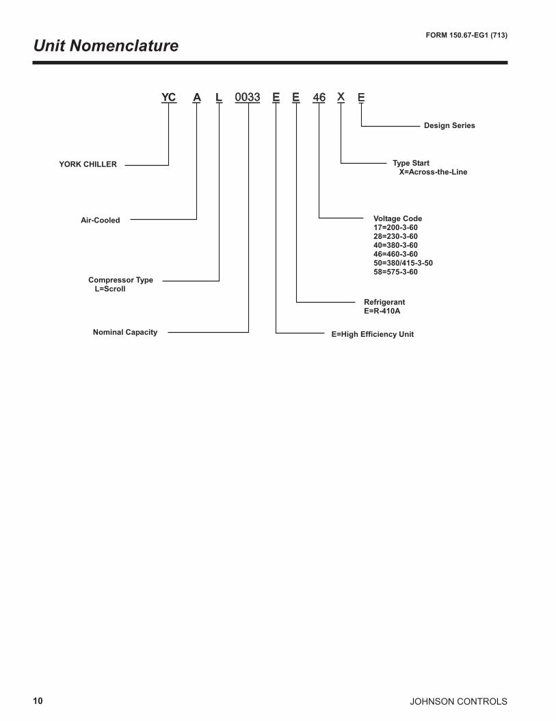
Unit Nomenclature
���� � � �� � �
������������
����������
�� ����������������������
�� ������������
�������������
�����������������������������
���������������� ����� �� ������������������������������������������������
�������������������
���������������������
JOHNSON CONTROLS 11
FORM 150.67-EG1 (713)
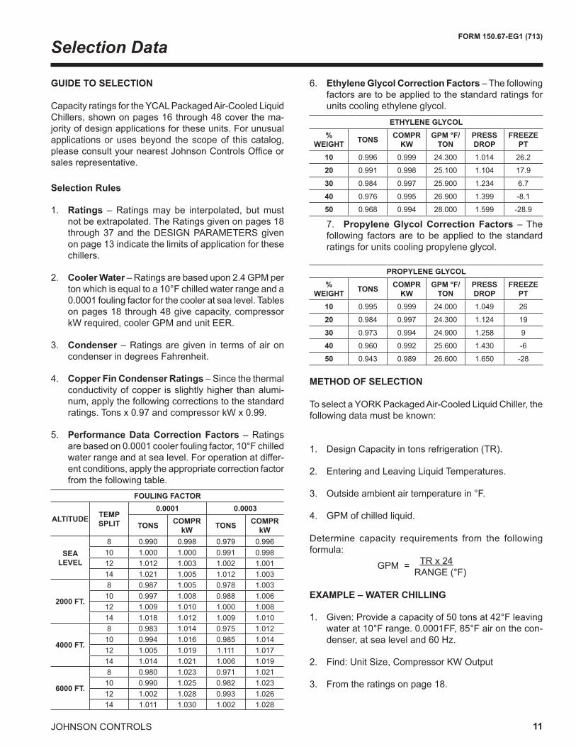
GUIDE TO SELECTION
Capacity ratings for the YCAL Packaged Air-Cooled Liquid Chillers, shown on pages 16 through 48 cover the ma-jority of design applications for these units. For unusual applications or uses beyond the scope of this catalog, please consult your nearest Johnson Controls Office or sales representative.
Selection Rules
1. Ratings – Ratings may be interpolated, but must not be extrapolated. The Ratings given on pages 18 through 37 and the DESIGN PARAMETERS given on page 13 indicate the limits of application for these chillers.
2. Cooler Water – Ratings are based upon 2.4 GPM per ton which is equal to a 10°F chilled water range and a 0.0001 fouling factor for the cooler at sea level. Tables on pages 18 through 48 give capacity, compressor kW required, cooler GPM and unit EER.
3. Condenser – Ratings are given in terms of air on condenser in degrees Fahrenheit.
4. Copper Fin Condenser Ratings – Since the thermal conductivity of copper is slightly higher than alumi-num, apply the following corrections to the standard ratings. Tons x 0.97 and compressor kW x 0.99.
5. Performance Data Correction Factors – Ratings are based on 0.0001 cooler fouling factor, 10°F chilled water range and at sea level. For operation at differ-ent conditions, apply the appropriate correction factor from the following table.
METHOD OF SELECTION
To select a YORK Packaged Air-Cooled Liquid Chiller, the following data must be known:
1. Design Capacity in tons refrigeration (TR).
2. Entering and Leaving Liquid Temperatures.
3. Outside ambient air temperature in °F.
4. GPM of chilled liquid.
Determine capacity requirements from the following formula: GPM = TR x 24 RANGE (°F)
EXAMPLE – WATER CHILLING
1. Given: Provide a capacity of 50 tons at 42°F leaving water at 10°F range. 0.0001FF, 85°F air on the con-denser, at sea level and 60 Hz.
2. Find: Unit Size, Compressor KW Output
3. From the ratings on page 18.
6. Ethylene Glycol Correction Factors – The following factors are to be applied to the standard ratings for units cooling ethylene glycol.
7. Propylene Glycol Correction Factors – The following factors are to be applied to the standard ratings for units cooling propylene glycol.
Selection Data
FOULING FACTOR
ALTITUDE TEMP SPLIT
0.0001 0.0003
TONS COMPR kW TONS COMPR
kW
SEA LEVEL
8 0.990 0.998 0.979 0.99610 1.000 1.000 0.991 0.99812 1.012 1.003 1.002 1.00114 1.021 1.005 1.012 1.003
2000 FT.
8 0.987 1.005 0.978 1.00310 0.997 1.008 0.988 1.00612 1.009 1.010 1.000 1.00814 1.018 1.012 1.009 1.010
4000 FT.
8 0.983 1.014 0.975 1.01210 0.994 1.016 0.985 1.01412 1.005 1.019 1.111 1.01714 1.014 1.021 1.006 1.019
6000 FT.
8 0.980 1.023 0.971 1.02110 0.990 1.025 0.982 1.02312 1.002 1.028 0.993 1.02614 1.011 1.030 1.002 1.028
ETHYLENE GLYCOL%
WEIGHT TONS COMPR KW
GPM °F/TON
PRESS DROP
FREEZE PT
10 0.996 0.999 24.300 1.014 26.2
20 0.991 0.998 25.100 1.104 17.9
30 0.984 0.997 25.900 1.234 6.7
40 0.976 0.995 26.900 1.399 -8.1
50 0.968 0.994 28.000 1.599 -28.9
PROPYLENE GLYCOL%
WEIGHT TONS COMPR KW
GPM °F/TON
PRESS DROP
FREEZE PT
10 0.995 0.999 24.000 1.049 26
20 0.984 0.997 24.300 1.124 19
30 0.973 0.994 24.900 1.258 9
40 0.960 0.992 25.600 1.430 -6
50 0.943 0.989 26.600 1.650 -28
12
FORM 150.67-EG1 (713)
JOHNSON CONTROLS
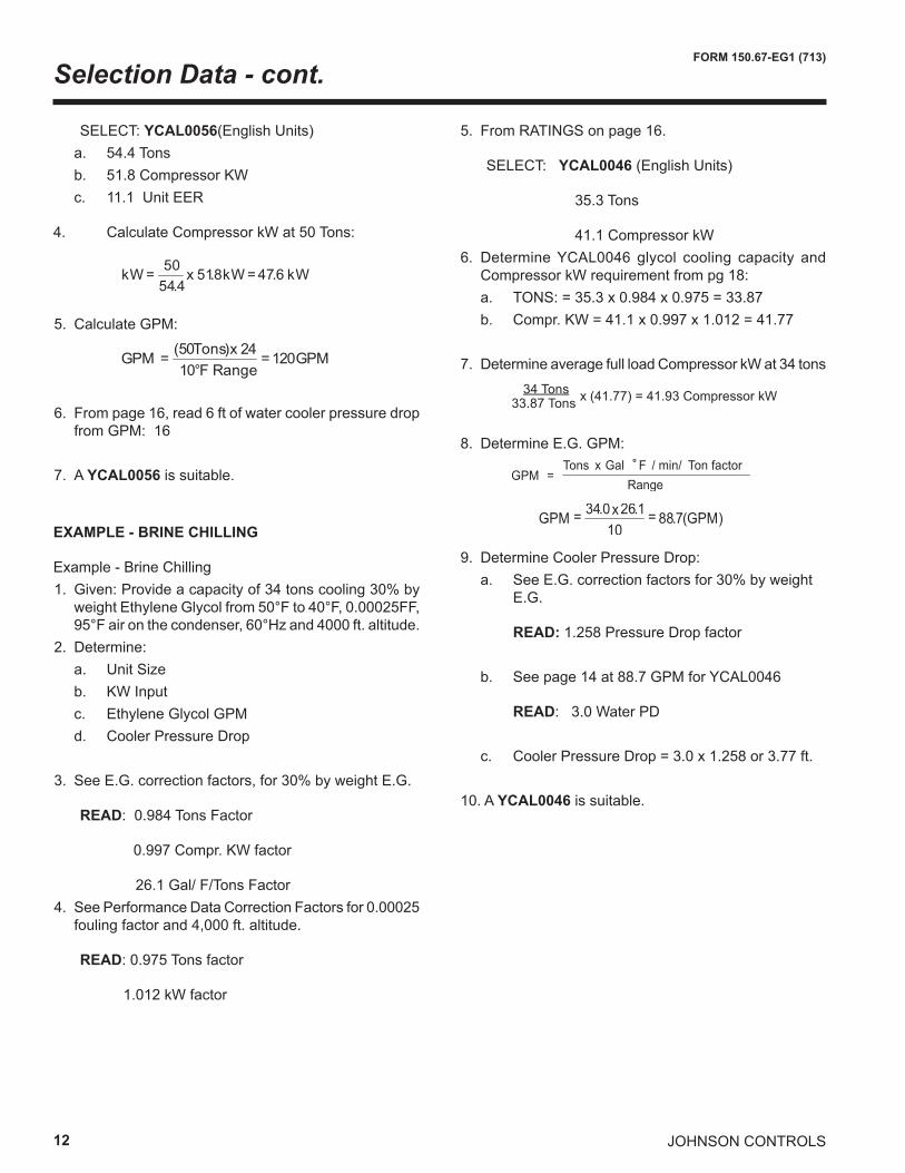
SELECT: YCAL0056(English Units) a. 54.4 Tons b. 51.8 Compressor KW c. 11.1 Unit EER
4. Calculate Compressor kW at 50 Tons:
5. Calculate GPM:
6. From page 16, read 6 ft of water cooler pressure drop from GPM: 16
7. A YCAL0056 is suitable.
EXAMPLE - BRINE CHILLING
Example - Brine Chilling1. Given: Provide a capacity of 34 tons cooling 30% by
weight Ethylene Glycol from 50°F to 40°F, 0.00025FF, 95°F air on the condenser, 60°Hz and 4000 ft. altitude.
2. Determine: a. Unit Size b. KW Input c. Ethylene Glycol GPM d. Cooler Pressure Drop
3. See E.G. correction factors, for 30% by weight E.G.
READ: 0.984 Tons Factor
0.997 Compr. KW factor
26.1 Gal/ F/Tons Factor4. See Performance Data Correction Factors for 0.00025
fouling factor and 4,000 ft. altitude.
READ: 0.975 Tons factor
1.012 kW factor
5. From RATINGS on page 16.
SELECT: YCAL0046 (English Units)
35.3 Tons
41.1 Compressor kW6. Determine YCAL0046 glycol cooling capacity and
Compressor kW requirement from pg 18: a. TONS: = 35.3 x 0.984 x 0.975 = 33.87 b. Compr. KW = 41.1 x 0.997 x 1.012 = 41.77
7. Determine average full load Compressor kW at 34 tons
8. Determine E.G. GPM:
9. Determine Cooler Pressure Drop: a. See E.G. correction factors for 30% by weight
E.G.
READ: 1.258 Pressure Drop factor b. See page 14 at 88.7 GPM for YCAL0046
READ: 3.0 Water PD c. Cooler Pressure Drop = 3.0 x 1.258 or 3.77 ft.
10. A YCAL0046 is suitable.
kWkWxkW 6.478. 514 .54
50 ==
GPMF Range
Tons GPM 12010
24)50( =°
x=
��������������������������������� ���� �����������
�����������������������
��� ����
��������
�������� ������ ���
Selection Data - cont.
JOHNSON CONTROLS 13
FORM 150.67-EG1 (713)
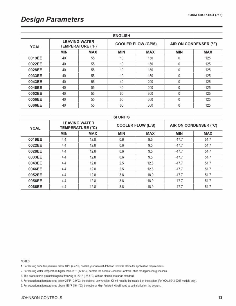
NOTES:1. For leaving brine temperature below 40°F (4.4°C), contact your nearest Johnson Controls Office for application requirements.2. For leaving water temperature higher than 55°F (12.8°C), contact the nearest Johnson Controls Office for application guidelines.3. The evaporator is protected against freezing to -20°F (-28.8°C) with an electric heater as standard.4. For operation at temperatures below 25°F (-3.9°C), the optional Low Ambient Kit will need to be installed on the system (for YCAL0043-0065 models only).5. For operation at temperatures above 115°F (46.1°C), the optional High Ambient Kit will need to be installed on the system.
Design Parameters
ENGLISH
YCALLEAVING WATER
TEMPERATURE (°F) COOLER FLOW (GPM) AIR ON CONDENSER (°F)
MIN MAX MIN MAX MIN MAX0019EE 40 55 10 150 0 1250022EE 40 55 10 150 0 1250028EE 40 55 10 150 0 1250033EE 40 55 10 150 0 1250043EE 40 55 40 200 0 1250046EE 40 55 40 200 0 1250052EE 40 55 60 300 0 1250056EE 40 55 60 300 0 1250066EE 40 55 60 300 0 125
SI UNITS
YCALLEAVING WATER
TEMPERATURE (°C) COOLER FLOW (L/S) AIR ON CONDENSER (°C)
MIN MAX MIN MAX MIN MAX0019EE 4.4 12.8 0.6 9.5 -17.7 51.70022EE 4.4 12.8 0.6 9.5 -17.7 51.70028EE 4.4 12.8 0.6 9.5 -17.7 51.70033EE 4.4 12.8 0.6 9.5 -17.7 51.70043EE 4.4 12.8 2.5 12.6 -17.7 51.70046EE 4.4 12.8 2.5 12.6 -17.7 51.70052EE 4.4 12.8 3.8 18.9 -17.7 51.70056EE 4.4 12.8 3.8 18.9 -17.7 51.70066EE 4.4 12.8 3.8 18.9 -17.7 51.7
14
FORM 150.67-EG1 (713)
JOHNSON CONTROLS
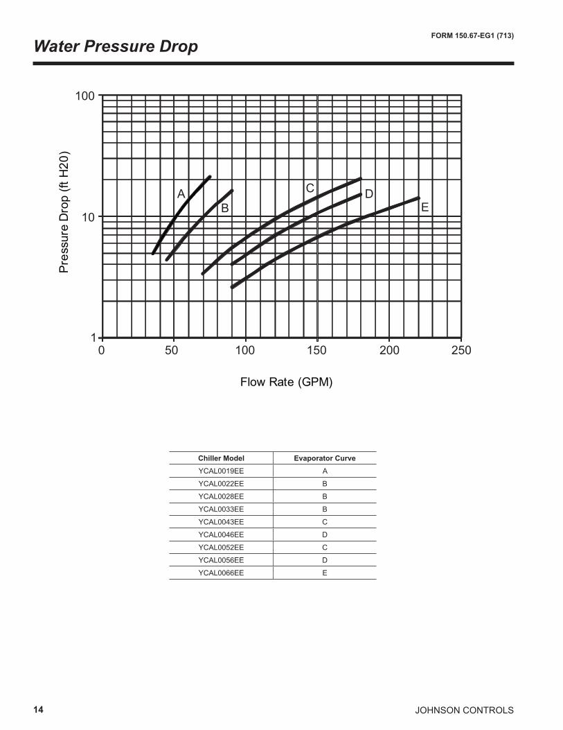
Water Pressure DropP
ress
ure
Dro
p (ft
H20
)
Flow Rate (GPM)
AB
C DE
100
10
10 50 100 150 200 250
Chiller Model Evaporator CurveYCAL0019EE A
YCAL0022EE B
YCAL0028EE B
YCAL0033EE B
YCAL0043EE C
YCAL0046EE D
YCAL0052EE C
YCAL0056EE D
YCAL0066EE E
JOHNSON CONTROLS 15
FORM 150.67-EG1 (713)
1
10
100
0 2 4 6 8 10 12 14 16
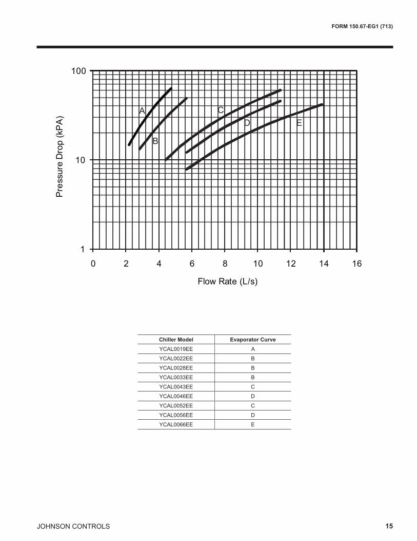
Pre
ssur
e D
rop
(kP
A)
Flow Rate (L/s)
A
B
CD E
Chiller Model Evaporator CurveYCAL0019EE A
YCAL0022EE B
YCAL0028EE B
YCAL0033EE B
YCAL0043EE C
YCAL0046EE D
YCAL0052EE C
YCAL0056EE D
YCAL0066EE E
16
FORM 150.67-EG1 (713)
JOHNSON CONTROLS
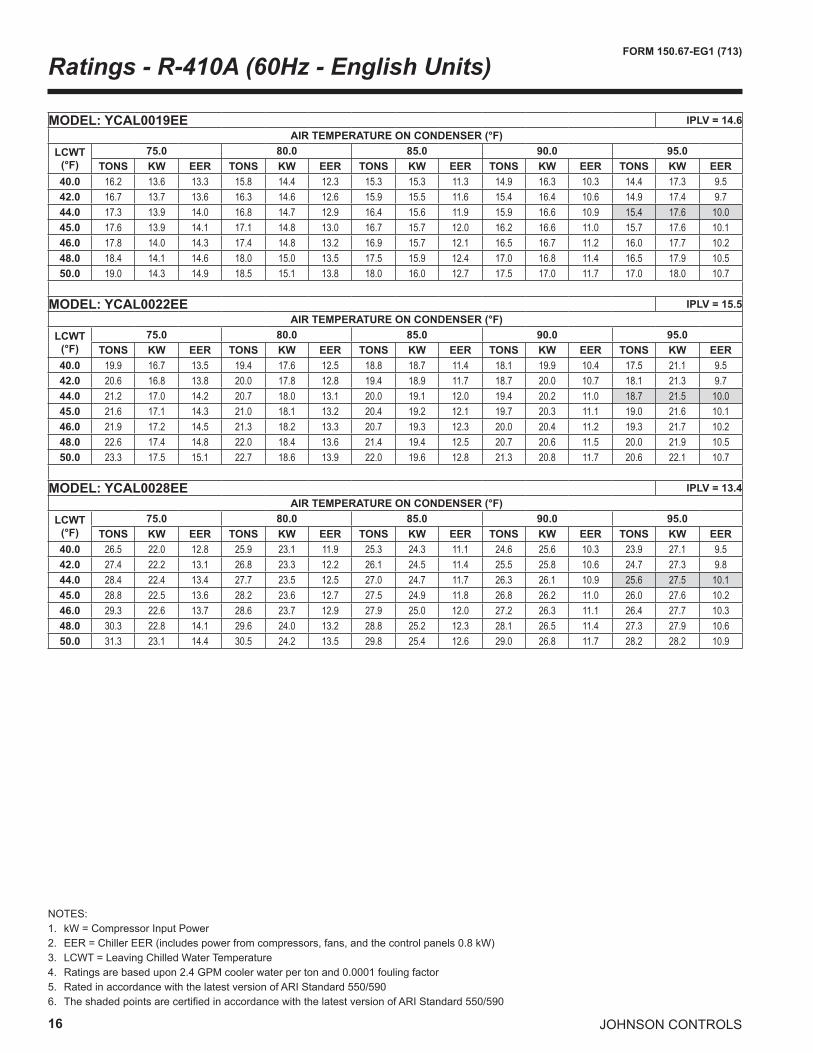
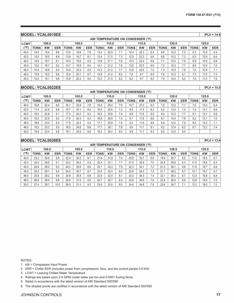
NOTES:1. kW = Compressor Input Power2. EER = Chiller EER (includes power from compressors, fans, and the control panels 0.8 kW)3. LCWT = Leaving Chilled Water Temperature4. Ratings are based upon 2.4 GPM cooler water per ton and 0.0001 fouling factor5. Rated in accordance with the latest version of ARI Standard 550/5906. The shaded points are certified in accordance with the latest version of ARI Standard 550/590
Ratings - R-410A (60Hz - English Units)
MODEL: YCAL0019EE IPLV = 14.6 AIR TEMPERATURE ON CONDENSER (°F)
LCWT(°F)
75.0 80.0 85.0 90.0 95.0TONS KW EER TONS KW EER TONS KW EER TONS KW EER TONS KW EER
40.0 16.2 13.6 13.3 15.8 14.4 12.3 15.3 15.3 11.3 14.9 16.3 10.3 14.4 17.3 9.542.0 16.7 13.7 13.6 16.3 14.6 12.6 15.9 15.5 11.6 15.4 16.4 10.6 14.9 17.4 9.744.0 17.3 13.9 14.0 16.8 14.7 12.9 16.4 15.6 11.9 15.9 16.6 10.9 15.4 17.6 10.045.0 17.6 13.9 14.1 17.1 14.8 13.0 16.7 15.7 12.0 16.2 16.6 11.0 15.7 17.6 10.146.0 17.8 14.0 14.3 17.4 14.8 13.2 16.9 15.7 12.1 16.5 16.7 11.2 16.0 17.7 10.248.0 18.4 14.1 14.6 18.0 15.0 13.5 17.5 15.9 12.4 17.0 16.8 11.4 16.5 17.9 10.550.0 19.0 14.3 14.9 18.5 15.1 13.8 18.0 16.0 12.7 17.5 17.0 11.7 17.0 18.0 10.7
MODEL: YCAL0022EE IPLV = 15.5 AIR TEMPERATURE ON CONDENSER (°F)
LCWT(°F)
75.0 80.0 85.0 90.0 95.0TONS KW EER TONS KW EER TONS KW EER TONS KW EER TONS KW EER
40.0 19.9 16.7 13.5 19.4 17.6 12.5 18.8 18.7 11.4 18.1 19.9 10.4 17.5 21.1 9.542.0 20.6 16.8 13.8 20.0 17.8 12.8 19.4 18.9 11.7 18.7 20.0 10.7 18.1 21.3 9.744.0 21.2 17.0 14.2 20.7 18.0 13.1 20.0 19.1 12.0 19.4 20.2 11.0 18.7 21.5 10.045.0 21.6 17.1 14.3 21.0 18.1 13.2 20.4 19.2 12.1 19.7 20.3 11.1 19.0 21.6 10.146.0 21.9 17.2 14.5 21.3 18.2 13.3 20.7 19.3 12.3 20.0 20.4 11.2 19.3 21.7 10.248.0 22.6 17.4 14.8 22.0 18.4 13.6 21.4 19.4 12.5 20.7 20.6 11.5 20.0 21.9 10.550.0 23.3 17.5 15.1 22.7 18.6 13.9 22.0 19.6 12.8 21.3 20.8 11.7 20.6 22.1 10.7
MODEL: YCAL0028EE IPLV = 13.4 AIR TEMPERATURE ON CONDENSER (°F)
LCWT(°F)
75.0 80.0 85.0 90.0 95.0TONS KW EER TONS KW EER TONS KW EER TONS KW EER TONS KW EER
40.0 26.5 22.0 12.8 25.9 23.1 11.9 25.3 24.3 11.1 24.6 25.6 10.3 23.9 27.1 9.542.0 27.4 22.2 13.1 26.8 23.3 12.2 26.1 24.5 11.4 25.5 25.8 10.6 24.7 27.3 9.844.0 28.4 22.4 13.4 27.7 23.5 12.5 27.0 24.7 11.7 26.3 26.1 10.9 25.6 27.5 10.145.0 28.8 22.5 13.6 28.2 23.6 12.7 27.5 24.9 11.8 26.8 26.2 11.0 26.0 27.6 10.246.0 29.3 22.6 13.7 28.6 23.7 12.9 27.9 25.0 12.0 27.2 26.3 11.1 26.4 27.7 10.348.0 30.3 22.8 14.1 29.6 24.0 13.2 28.8 25.2 12.3 28.1 26.5 11.4 27.3 27.9 10.650.0 31.3 23.1 14.4 30.5 24.2 13.5 29.8 25.4 12.6 29.0 26.8 11.7 28.2 28.2 10.9
JOHNSON CONTROLS 17
FORM 150.67-EG1 (713)
NOTES:1. kW = Compressor Input Power2. EER = Chiller EER (includes power from compressors, fans, and the control panels 0.8 kW)3. LCWT = Leaving Chilled Water Temperature4. Ratings are based upon 2.4 GPM cooler water per ton and 0.0001 fouling factor5. Rated in accordance with the latest version of ARI Standard 550/5906. The shaded points are certified in accordance with the latest version of ARI Standard 550/590
MODEL: YCAL0019EE IPLV = 14.6AIR TEMPERATURE ON CONDENSER (°F)
LCWT(°F)
100.0 105.0 110.0 115.0 120.0 125.0TONS KW EER TONS KW EER TONS KW EER TONS KW EER TONS KW EER TONS KW EER
40.0 14.0 18.4 8.6 13.5 19.6 7.8 13.0 20.9 7.1 12.4 22.2 6.4 6.6 10.2 7.0 6.3 10.9 6.442.0 14.5 18.5 8.9 13.9 19.7 8.1 13.4 21.0 7.3 12.9 22.3 6.6 6.8 10.2 7.3 6.5 10.9 6.644.0 14.9 18.7 9.1 14.4 19.9 8.3 13.9 21.1 7.5 13.3 22.4 6.8 7.1 10.3 7.6 6.8 10.9 6.845.0 15.2 18.7 9.2 14.7 19.9 8.4 14.1 21.2 7.6 13.5 22.5 6.9 7.2 10.3 7.7 6.9 10.9 7.046.0 15.4 18.8 9.4 14.9 20.0 8.5 14.3 21.2 7.7 13.8 22.6 7.0 7.3 10.3 7.8 7.0 10.9 7.148.0 15.9 19.0 9.6 15.4 20.1 8.7 14.8 21.4 8.0 7.9 9.7 8.9 7.6 10.3 8.1 7.3 11.0 7.350.0 16.5 19.1 9.8 15.9 20.3 9.0 15.3 21.5 8.2 8.2 9.7 9.2 7.9 10.4 8.3 7.6 11.0 7.6
MODEL: YCAL0022EE IPLV = 15.5AIR TEMPERATURE ON CONDENSER (°F)
LCWT(°F)
100.0 105.0 110.0 115.0 120.0 125.0TONS KW EER TONS KW EER TONS KW EER TONS KW EER TONS KW EER TONS KW EER
40.0 16.8 22.4 8.6 16.1 23.9 7.8 15.4 25.4 7.0 14.7 27.0 6.3 7.9 12.2 7.1 7.5 13.0 6.442.0 17.4 22.6 8.8 16.7 24.1 8.0 16.0 25.6 7.2 8.6 11.5 8.2 8.2 12.3 7.4 7.8 13.1 6.644.0 18.0 22.8 9.1 17.3 24.2 8.2 16.5 25.8 7.4 8.9 11.6 8.5 8.5 12.3 7.7 8.1 13.1 6.945.0 18.3 22.9 9.2 17.6 24.3 8.3 16.8 25.9 7.5 9.1 11.6 8.6 8.7 12.4 7.8 8.2 13.1 7.046.0 18.6 23.0 9.3 17.9 24.4 8.4 17.1 25.9 7.6 9.2 11.6 8.8 8.8 12.4 7.9 8.4 13.2 7.148.0 19.2 23.2 9.5 18.5 24.6 8.6 17.7 26.1 7.8 9.6 11.7 9.1 9.2 12.4 8.2 8.7 13.2 7.450.0 19.9 23.4 9.8 19.1 24.9 8.9 18.3 26.4 8.0 9.9 11.7 9.3 9.5 12.5 8.4
MODEL: YCAL0028EE IPLV = 13.4AIR TEMPERATURE ON CONDENSER (°F)
LCWT(°F)
100.0 105.0 110.0 115.0 120.0 125.0TONS KW EER TONS KW EER TONS KW EER TONS KW EER TONS KW EER TONS KW EER
40.0 23.2 28.6 8.8 22.4 30.2 8.1 21.6 31.9 7.4 20.8 33.7 6.8 19.9 35.7 6.2 11.0 18.5 6.142.0 24.0 28.8 9.1 23.2 30.4 8.3 22.4 32.1 7.7 21.5 33.9 7.0 20.6 35.9 6.4 11.5 18.6 6.444.0 24.8 29.0 9.3 24.0 30.6 8.6 23.1 32.3 7.9 22.3 34.1 7.2 21.3 36.1 6.6 11.9 18.7 6.645.0 25.2 29.1 9.4 24.4 30.7 8.7 23.5 32.4 8.0 22.6 34.2 7.3 21.7 36.2 6.7 12.1 18.7 6.746.0 25.6 29.2 9.6 24.8 30.8 8.8 23.9 32.5 8.1 23.0 34.3 7.4 22.1 36.3 6.7 12.3 18.8 6.848.0 26.5 29.4 9.8 25.6 31.0 9.0 24.7 32.7 8.3 23.8 34.6 7.6 22.8 36.5 6.9 12.8 18.9 7.050.0 27.4 29.7 10.0 26.5 31.3 9.3 25.6 33.0 8.5 24.6 34.8 7.8 23.6 36.7 7.1 13.2 19.0 7.2

18
FORM 150.67-EG1 (713)
JOHNSON CONTROLS
NOTES:1. kW = Compressor Input Power2. EER = Chiller EER (includes power from compressors, fans, and the control panels 0.8 kW)3. LCWT = Leaving Chilled Water Temperature4. Ratings are based upon 2.4 GPM cooler water per ton and 0.0001 fouling factor5. Rated in accordance with the latest version of ARI Standard 550/5906. The shaded points are certified in accordance with the latest version of ARI Standard 550/590
Ratings - R-410A (60Hz - English Units) - continued
MODEL: YCAL0033EE IPLV = 14.5 AIR TEMPERATURE ON CONDENSER (°F)
LCWT(°F)
75.0 80.0 85.0 90.0 95.0TONS KW EER TONS KW EER TONS KW EER TONS KW EER TONS KW EER
40.0 29.7 23.8 13.3 29.0 25.0 12.4 28.3 26.3 11.6 27.5 27.7 10.8 26.7 29.2 10.042.0 30.7 24.0 13.6 30.0 25.2 12.8 29.2 26.5 11.9 28.5 27.9 11.1 27.6 29.4 10.244.0 31.7 24.2 14.0 31.0 25.4 13.1 30.2 26.7 12.2 29.4 28.1 11.3 28.6 29.6 10.545.0 32.2 24.4 14.1 31.5 25.6 13.2 30.7 26.9 12.3 29.9 28.3 11.5 29.0 29.8 10.646.0 32.7 24.5 14.3 32.0 25.7 13.4 31.2 27.0 12.5 30.4 28.4 11.6 29.5 29.9 10.848.0 33.7 24.8 14.6 33.0 26.0 13.7 32.2 27.3 12.8 31.4 28.7 11.9 30.5 30.2 11.050.0 34.8 25.1 14.9 34.0 26.3 14.0 33.2 27.6 13.0 32.3 29.0 12.1 31.4 30.5 11.3
MODEL: YCAL0043EE IPLV = 14.5 AIR TEMPERATURE ON CONDENSER (°F)
LCWT(°F)
75.0 80.0 85.0 90.0 95.0TONS KW EER TONS KW EER TONS KW EER TONS KW EER TONS KW EER
40.0 38.7 30.8 12.8 37.8 32.3 11.9 36.8 34.1 11.1 35.7 36.2 10.3 34.6 38.4 9.442.0 40.0 31.0 13.1 39.1 32.5 12.3 38.1 34.3 11.5 37.1 36.4 10.6 35.9 38.6 9.844.0 41.4 31.1 13.5 40.5 32.7 12.7 39.5 34.6 11.8 38.4 36.6 10.9 37.2 38.8 10.145.0 42.1 31.2 13.7 41.1 32.8 12.8 40.1 34.7 12.0 39.1 36.7 11.1 37.9 38.9 10.246.0 42.7 31.3 13.9 41.8 32.9 13.0 40.8 34.8 12.1 39.7 36.8 11.3 38.6 39.0 10.448.0 44.1 31.5 14.3 43.2 33.2 13.4 42.2 35.0 12.5 41.1 37.0 11.6 39.9 39.3 10.750.0 45.6 31.7 14.6 44.7 33.4 13.8 43.6 35.2 12.8 42.5 37.3 11.9 41.3 39.5 11.0
MODEL: YCAL0046EE IPLV = 14.7 AIR TEMPERATURE ON CONDENSER (°F)
LCWT(°F)
75.0 80.0 85.0 90.0 95.0TONS KW EER TONS KW EER TONS KW EER TONS KW EER TONS KW EER
40.0 41.0 32.4 13.0 40.0 34.2 12.1 39.0 36.1 11.2 37.9 38.2 10.4 36.7 40.5 9.542.0 42.5 32.6 13.3 41.4 34.4 12.4 40.4 36.3 11.6 39.2 38.4 10.7 38.1 40.8 9.944.0 43.9 32.9 13.7 42.9 34.6 12.8 41.8 36.6 11.9 40.6 38.7 11.0 39.4 41.0 10.245.0 44.7 33.0 13.9 43.6 34.8 13.0 42.5 36.7 12.1 41.4 38.8 11.2 40.1 41.1 10.346.0 45.4 33.1 14.1 44.4 34.9 13.1 43.2 36.8 12.2 42.1 39.0 11.3 40.8 41.3 10.548.0 46.9 33.4 14.4 45.9 35.2 13.5 44.7 37.1 12.6 43.5 39.2 11.7 42.3 41.5 10.850.0 48.5 33.6 14.8 47.4 35.4 13.9 46.2 37.4 12.9 45.0 39.5 12.0 43.7 41.8 11.1

JOHNSON CONTROLS 19
FORM 150.67-EG1 (713)
NOTES:1. kW = Compressor Input Power2. EER = Chiller EER (includes power from compressors, fans, and the control panels 0.8 kW)3. LCWT = Leaving Chilled Water Temperature4. Ratings are based upon 2.4 GPM cooler water per ton and 0.0001 fouling factor5. Rated in accordance with the latest version of ARI Standard 550/5906. The shaded points are certified in accordance with the latest version of ARI Standard 550/590
MODEL: YCAL0033EE IPLV= 14.5AIR TEMPERATURE ON CONDENSER (°F)
LCWT(°F)
100.0 105.0 110.0 115.0 120.0 125.0TONS KW EER TONS KW EER TONS KW EER TONS KW EER TONS KW EER TONS KW EER
40.0 25.9 30.8 9.2 25.0 32.5 8.5 24.1 34.3 7.8 23.2 36.2 7.1 22.2 38.3 6.4 11.6 18.3 6.542.0 26.8 31.0 9.5 25.9 32.7 8.7 24.9 34.5 8.0 24.0 36.5 7.3 23.0 38.5 6.6 12.1 18.4 6.844.0 27.7 31.2 9.7 26.8 33.0 8.9 25.8 34.8 8.2 24.8 36.7 7.5 23.8 38.8 6.8 12.5 18.4 7.045.0 28.1 31.4 9.8 27.2 33.1 9.0 26.2 34.9 8.3 25.2 36.8 7.6 24.2 38.9 6.9 12.7 18.5 7.146.0 28.6 31.5 9.9 27.7 33.2 9.2 26.7 35.0 8.4 25.7 37.0 7.7 24.6 39.0 7.0 13.0 18.5 7.248.0 29.5 31.8 10.2 28.6 33.5 9.4 27.6 35.3 8.6 26.5 37.2 7.9 25.4 39.3 7.2 13.4 18.6 7.550.0 30.5 32.1 10.4 29.5 33.8 9.6 28.5 35.6 8.9 27.4 37.5 8.1 14.5 17.8 8.4 13.9 18.7 7.7
MODEL: YCAL0043EE IPLV= 14.5AIR TEMPERATURE ON CONDENSER (°F)
LCWT(°F)
100.0 105.0 110.0 115.0 120.0 125.0TONS KW EER TONS KW EER TONS KW EER TONS KW EER TONS KW EER TONS KW EER
40.0 33.5 40.9 8.6 32.2 43.6 7.9 30.9 46.5 7.1 29.6 49.7 6.4 28.2 53.1 5.8 14.3 25.5 5.542.0 34.7 41.1 8.9 33.5 43.8 8.1 32.2 46.7 7.4 30.8 49.8 6.7 29.4 53.2 6.0 15.0 25.5 5.844.0 36.0 41.3 9.2 34.7 44.0 8.4 33.4 46.8 7.6 32.0 50.0 6.9 30.6 53.3 6.2 15.6 25.5 6.045.0 36.7 41.4 9.4 35.4 44.1 8.6 34.0 46.9 7.8 32.6 50.0 7.0 31.2 53.4 6.3 15.9 25.5 6.146.0 37.3 41.5 9.5 36.0 44.2 8.7 34.7 47.0 7.9 33.2 50.1 7.2 31.8 53.5 6.5 16.2 25.5 6.348.0 38.7 41.7 9.8 37.4 44.4 9.0 36.0 47.2 8.2 34.5 50.3 7.4 33.0 53.6 6.7 16.9 25.6 6.550.0 40.1 42.0 10.1 38.7 44.6 9.2 37.3 47.5 8.4 35.8 50.5 7.6 34.2 53.8 6.9 17.6 25.6 6.8
MODEL: YCAL0046EE IPLV= 14.7AIR TEMPERATURE ON CONDENSER (°F)
LCWT(°F)
100.0 105.0 110.0 115.0 120.0 125.0TONS KW EER TONS KW EER TONS KW EER TONS KW EER TONS KW EER TONS KW EER
40.0 35.4 43.0 8.7 34.2 45.7 8.0 32.8 48.6 7.3 31.4 51.7 6.6 30.0 55.1 5.9 15.2 26.4 5.742.0 36.8 43.2 9.0 35.5 45.9 8.3 34.1 48.8 7.5 32.7 51.9 6.8 31.2 55.2 6.2 15.9 26.4 5.944.0 38.2 43.5 9.3 36.8 46.2 8.5 35.4 49.1 7.8 34.0 52.1 7.1 32.4 55.4 6.4 16.5 26.5 6.245.0 38.9 43.6 9.5 37.5 46.3 8.7 36.1 49.2 7.9 34.6 52.3 7.2 33.1 55.6 6.5 16.9 26.5 6.346.0 39.5 43.8 9.6 38.2 46.4 8.8 36.8 49.3 8.0 35.3 52.4 7.3 33.7 55.7 6.6 17.2 26.5 6.448.0 40.9 44.0 9.9 39.6 46.7 9.1 38.1 49.6 8.3 36.6 52.6 7.5 35.0 55.9 6.8 17.9 26.6 6.750.0 42.4 44.3 10.2 41.0 47.0 9.3 39.5 49.8 8.5 37.9 52.9 7.8 36.3 56.2 7.1 18.6 26.7 6.9

20
FORM 150.67-EG1 (713)
JOHNSON CONTROLS
NOTES:1. kW = Compressor Input Power2. EER = Chiller EER (includes power from compressors, fans, and the control panels 0.8 kW)3. LCWT = Leaving Chilled Water Temperature4. Ratings are based upon 2.4 GPM cooler water per ton and 0.0001 fouling factor5. Rated in accordance with the latest version of ARI Standard 550/5906. The shaded points are certified in accordance with the latest version of ARI Standard 550/590
MODEL: YCAL0052EE IPLV = 15.1 AIR TEMPERATURE ON CONDENSER (°F)
LCWT(°F)
75.0 80.0 85.0 90.0 95.0TONS KW EER TONS KW EER TONS KW EER TONS KW EER TONS KW EER
40.0 47.7 38.0 12.8 46.6 40.1 12.0 45.5 42.3 11.1 44.3 44.7 10.3 43.1 47.2 9.642.0 49.4 38.3 13.2 48.3 40.4 12.3 47.1 42.6 11.5 45.9 45.0 10.6 44.7 47.6 9.944.0 51.2 38.7 13.5 50.0 40.8 12.6 48.8 43.0 11.8 47.5 45.4 10.9 46.2 47.9 10.245.0 52.0 38.9 13.7 50.8 40.9 12.8 49.6 43.2 11.9 48.3 45.5 11.1 47.0 48.1 10.346.0 52.9 39.0 13.9 51.7 41.1 13.0 50.5 43.3 12.1 49.2 45.7 11.3 47.8 48.3 10.448.0 54.8 39.4 14.2 53.5 41.5 13.3 52.2 43.7 12.4 50.9 46.1 11.6 49.5 48.6 10.750.0 56.6 39.8 14.6 55.3 41.9 13.7 54.0 44.1 12.7 52.6 46.5 11.9 51.1 49.0 11.0
MODEL: YCAL0056EE IPLV = 14.7 AIR TEMPERATURE ON CONDENSER (°F)
LCWT(°F)
75.0 80.0 85.0 90.0 95.0TONS KW EER TONS KW EER TONS KW EER TONS KW EER TONS KW EER
40.0 58.2 48.2 12.7 56.9 50.7 11.9 55.5 53.3 11.1 54.1 56.2 10.3 52.5 59.3 9.542.0 60.2 48.7 13.0 58.9 51.2 12.2 57.5 53.8 11.4 55.9 56.7 10.6 54.3 59.8 9.844.0 62.3 49.2 13.4 60.9 51.7 12.5 59.4 54.4 11.7 57.9 57.2 10.9 56.2 60.3 10.145.0 63.3 49.5 13.5 61.9 52.0 12.7 60.4 54.6 11.8 58.8 57.5 11.0 57.2 60.6 10.246.0 64.4 49.7 13.7 62.9 52.2 12.8 61.4 54.9 12.0 59.8 57.8 11.1 58.1 60.9 10.348.0 66.5 50.3 14.0 65.0 52.8 13.1 63.5 55.5 12.2 61.8 58.3 11.4 60.0 61.4 10.650.0 68.6 50.9 14.3 67.1 53.4 13.4 65.5 56.1 12.5 63.8 58.9 11.7 62.0 62.0 10.8
MODEL: YCAL0066EE IPLV = 15.1 AIR TEMPERATURE ON CONDENSER (°F)
LCWT(°F)
75.0 80.0 85.0 90.0 95.0TONS KW EER TONS KW EER TONS KW EER TONS KW EER TONS KW EER
40.0 68.6 58.0 12.7 67.0 60.8 11.9 65.3 63.9 11.1 63.5 67.2 10.3 61.7 70.8 9.542.0 71.0 58.6 13.1 69.3 61.5 12.2 67.6 64.5 11.4 65.8 67.9 10.6 63.9 71.4 9.844.0 73.5 59.2 13.4 71.7 62.1 12.5 69.9 65.2 11.7 68.1 68.5 10.9 66.1 72.1 10.145.0 74.7 59.6 13.5 73.0 62.4 12.7 71.1 65.6 11.8 69.2 68.9 11.0 67.3 72.5 10.246.0 76.0 59.9 13.7 74.2 62.8 12.8 72.3 65.9 11.9 70.4 69.2 11.1 68.4 72.8 10.348.0 78.6 60.6 14.0 76.7 63.5 13.1 74.8 66.6 12.2 72.8 70.0 11.4 70.8 73.6 10.650.0 81.1 61.3 14.3 79.2 64.2 13.4 77.3 67.4 12.5 75.2 70.8 11.7 73.1 74.3 10.8
Ratings - R-410A (60Hz - English Units) - continued

JOHNSON CONTROLS 21
FORM 150.67-EG1 (713)
NOTES:1. kW = Compressor Input Power2. EER = Chiller EER (includes power from compressors, fans, and the control panels 0.8 kW)3. LCWT = Leaving Chilled Water Temperature4. Ratings are based upon 2.4 GPM cooler water per ton and 0.0001 fouling factor5. Rated in accordance with the latest version of ARI Standard 550/5906. The shaded points are certified in accordance with the latest version of ARI Standard 550/590
MODEL: YCAL0052EE IPLV= 15.1AIR TEMPERATURE ON CONDENSER (°F)
LCWT(°F)
100.0 105.0 110.0 115.0 120.0 125.0TONS KW EER TONS KW EER TONS KW EER TONS KW EER TONS KW EER TONS KW EER
40.0 41.9 49.9 8.9 40.5 52.8 8.2 39.1 55.8 7.5 37.6 59.1 6.9 36.1 62.5 6.3 18.5 30.1 6.042.0 43.4 50.3 9.1 42.0 53.1 8.4 40.5 56.2 7.7 39.0 59.4 7.1 37.4 62.9 6.4 19.3 30.2 6.344.0 44.9 50.6 9.4 43.5 53.5 8.7 42.0 56.5 8.0 40.4 59.8 7.3 38.7 63.2 6.6 20.0 30.4 6.545.0 45.6 50.8 9.5 44.2 53.7 8.8 42.7 56.7 8.1 41.1 60.0 7.4 39.4 63.4 6.7 20.4 30.4 6.646.0 46.4 51.0 9.7 45.0 53.8 8.9 43.4 56.9 8.2 41.8 60.1 7.5 40.1 63.6 6.8 20.8 30.5 6.748.0 48.0 51.3 9.9 46.5 54.2 9.2 44.9 57.3 8.4 43.3 60.5 7.7 41.5 64.0 7.0 21.5 30.6 6.950.0 49.6 51.7 10.2 48.1 54.6 9.4 46.5 57.7 8.7 44.7 60.9 7.9 42.9 64.4 7.2 22.3 30.7 7.2
MODEL: YCAL0056EE IPLV= 14.7AIR TEMPERATURE ON CONDENSER (°F)
LCWT(°F)
100.0 105.0 110.0 115.0 120.0 125.0TONS KW EER TONS KW EER TONS KW EER TONS KW EER TONS KW EER TONS KW EER
40.0 50.8 62.6 8.8 49.1 66.1 8.1 47.3 69.8 7.4 45.4 73.8 6.8 43.5 78.0 6.2 22.7 37.0 6.242.0 52.6 63.1 9.0 50.9 66.6 8.3 49.0 70.3 7.6 47.1 74.3 7.0 45.1 78.5 6.3 23.6 37.1 6.544.0 54.5 63.6 9.3 52.6 67.1 8.6 50.7 70.8 7.8 48.7 74.8 7.2 25.6 35.3 7.3 24.5 37.3 6.745.0 55.4 63.9 9.4 53.5 67.4 8.7 51.6 71.1 8.0 49.6 75.1 7.3 26.1 35.4 7.4 25.0 37.4 6.846.0 56.3 64.1 9.5 54.4 67.6 8.8 52.5 71.4 8.1 50.4 75.3 7.4 26.5 35.5 7.5 25.4 37.5 6.948.0 58.2 64.7 9.8 56.3 68.2 9.0 54.3 71.9 8.3 52.2 75.9 7.6 27.5 35.7 7.8 26.4 37.7 7.150.0 60.1 65.3 10.0 58.1 68.8 9.2 56.1 72.5 8.5 53.9 76.5 7.8 28.5 35.9 8.0 27.4 37.9 7.4
MODEL: YCAL0066EE IPLV= 15.1AIR TEMPERATURE ON CONDENSER (°F)
LCWT(°F)
100.0 105.0 110.0 115.0 120.0 125.0TONS KW EER TONS KW EER TONS KW EER TONS KW EER TONS KW EER TONS KW EER
40.0 59.8 74.7 8.8 57.8 78.8 8.1 55.8 83.3 7.4 53.8 88.2 6.8 51.6 93.5 6.2 26.6 44.3 6.342.0 61.9 75.3 9.1 59.9 79.5 8.3 57.9 84.0 7.7 55.7 88.8 7.0 40.1 63.8 6.8 27.7 44.5 6.544.0 64.1 76.0 9.3 62.1 80.2 8.6 59.9 84.6 7.9 57.7 89.5 7.2 30.0 42.2 7.3 28.8 44.7 6.745.0 65.2 76.3 9.4 63.1 80.5 8.7 61.0 85.0 8.0 58.8 89.8 7.3 30.5 42.4 7.5 29.3 44.8 6.846.0 66.4 76.7 9.5 64.2 80.9 8.8 62.0 85.4 8.1 59.8 90.2 7.4 31.1 42.5 7.6 29.9 44.9 6.948.0 68.6 77.5 9.8 66.5 81.6 9.0 64.2 86.1 8.3 61.9 90.9 7.6 32.3 42.8 7.8 31.0 45.2 7.250.0 71.0 78.2 10.0 68.7 82.4 9.3 66.4 86.9 8.5 64.0 91.7 7.8 33.5 43.0 8.1 32.2 45.5 7.4
22
FORM 150.67-EG1 (713)
JOHNSON CONTROLS
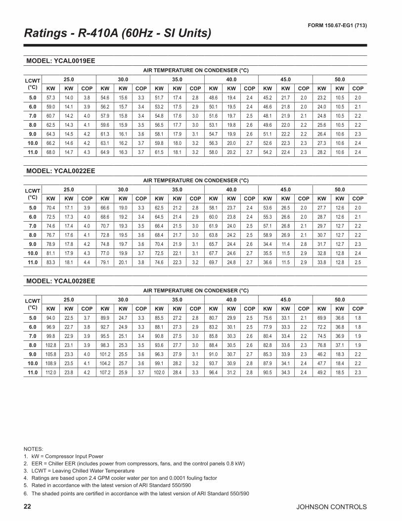
NOTES:1. kW = Compressor Input Power2. EER = Chiller EER (includes power from compressors, fans, and the control panels 0.8 kW)3. LCWT = Leaving Chilled Water Temperature4. Ratings are based upon 2.4 GPM cooler water per ton and 0.0001 fouling factor5. Rated in accordance with the latest version of ARI Standard 550/5906. The shaded points are certified in accordance with the latest version of ARI Standard 550/590
Ratings - R-410A (60Hz - SI Units)
MODEL: YCAL0019EE AIR TEMPERATURE ON CONDENSER (°C)
LCWT(°C)
25.0 30.0 35.0 40.0 45.0 50.0KW KW COP KW KW COP KW KW COP KW KW COP KW KW COP KW KW COP
5.0 57.3 14.0 3.8 54.6 15.6 3.3 51.7 17.4 2.8 48.6 19.4 2.4 45.2 21.7 2.0 23.2 10.5 2.06.0 59.0 14.1 3.9 56.2 15.7 3.4 53.2 17.5 2.9 50.1 19.5 2.4 46.6 21.8 2.0 24.0 10.5 2.17.0 60.7 14.2 4.0 57.9 15.8 3.4 54.8 17.6 3.0 51.6 19.7 2.5 48.1 21.9 2.1 24.8 10.5 2.28.0 62.5 14.3 4.1 59.6 15.9 3.5 56.5 17.7 3.0 53.1 19.8 2.6 49.6 22.0 2.2 25.6 10.5 2.29.0 64.3 14.5 4.2 61.3 16.1 3.6 58.1 17.9 3.1 54.7 19.9 2.6 51.1 22.2 2.2 26.4 10.6 2.3
10.0 66.2 14.6 4.2 63.1 16.2 3.7 59.8 18.0 3.2 56.3 20.0 2.7 52.6 22.3 2.3 27.3 10.6 2.411.0 68.0 14.7 4.3 64.9 16.3 3.7 61.5 18.1 3.2 58.0 20.2 2.7 54.2 22.4 2.3 28.2 10.6 2.4
MODEL: YCAL0022EE AIR TEMPERATURE ON CONDENSER (°C)
LCWT(°C)
25.0 30.0 35.0 40.0 45.0 50.0KW KW COP KW KW COP KW KW COP KW KW COP KW KW COP KW KW COP
5.0 70.4 17.1 3.9 66.6 19.0 3.3 62.5 21.2 2.8 58.1 23.7 2.4 53.6 26.5 2.0 27.7 12.6 2.06.0 72.5 17.3 4.0 68.6 19.2 3.4 64.5 21.4 2.9 60.0 23.8 2.4 55.3 26.6 2.0 28.7 12.6 2.17.0 74.6 17.4 4.0 70.7 19.3 3.5 66.4 21.5 3.0 61.9 24.0 2.5 57.1 26.8 2.1 29.7 12.7 2.28.0 76.7 17.6 4.1 72.8 19.5 3.6 68.4 21.7 3.0 63.8 24.2 2.5 58.9 26.9 2.1 30.7 12.7 2.29.0 78.9 17.8 4.2 74.8 19.7 3.6 70.4 21.9 3.1 65.7 24.4 2.6 34.4 11.4 2.8 31.7 12.7 2.3
10.0 81.1 17.9 4.3 77.0 19.9 3.7 72.5 22.1 3.1 67.7 24.6 2.7 35.5 11.5 2.9 32.8 12.8 2.411.0 83.3 18.1 4.4 79.1 20.1 3.8 74.6 22.3 3.2 69.7 24.8 2.7 36.6 11.5 2.9 33.8 12.8 2.5
MODEL: YCAL0028EE AIR TEMPERATURE ON CONDENSER (°C)
LCWT(°C)
25.0 30.0 35.0 40.0 45.0 50.0KW KW COP KW KW COP KW KW COP KW KW COP KW KW COP KW KW COP
5.0 94.0 22.5 3.7 89.9 24.7 3.3 85.5 27.2 2.8 80.7 29.9 2.5 75.6 33.1 2.1 69.9 36.6 1.86.0 96.9 22.7 3.8 92.7 24.9 3.3 88.1 27.3 2.9 83.2 30.1 2.5 77.9 33.3 2.2 72.2 36.8 1.87.0 99.8 22.9 3.9 95.5 25.1 3.4 90.8 27.5 3.0 85.8 30.3 2.6 80.4 33.4 2.2 74.5 36.9 1.98.0 102.8 23.1 3.9 98.3 25.3 3.5 93.6 27.7 3.0 88.4 30.5 2.6 82.8 33.6 2.3 76.8 37.1 1.99.0 105.8 23.3 4.0 101.2 25.5 3.6 96.3 27.9 3.1 91.0 30.7 2.7 85.3 33.9 2.3 46.2 18.3 2.2
10.0 108.9 23.5 4.1 104.2 25.7 3.6 99.1 28.2 3.2 93.7 30.9 2.8 87.9 34.1 2.4 47.7 18.4 2.211.0 112.0 23.8 4.2 107.2 25.9 3.7 102.0 28.4 3.3 96.4 31.2 2.8 90.5 34.3 2.4 49.2 18.5 2.3
JOHNSON CONTROLS 23
FORM 150.67-EG1 (713)
NOTES:1. kW = Compressor Input Power2. EER = Chiller EER (includes power from compressors, fans, and the control panels 0.8 kW)3. LCWT = Leaving Chilled Water Temperature4. Ratings are based upon 2.4 GPM cooler water per ton and 0.0001 fouling factor5. Rated in accordance with the latest version of ARI Standard 550/5906. The shaded points are certified in accordance with the latest version of ARI Standard 550/590
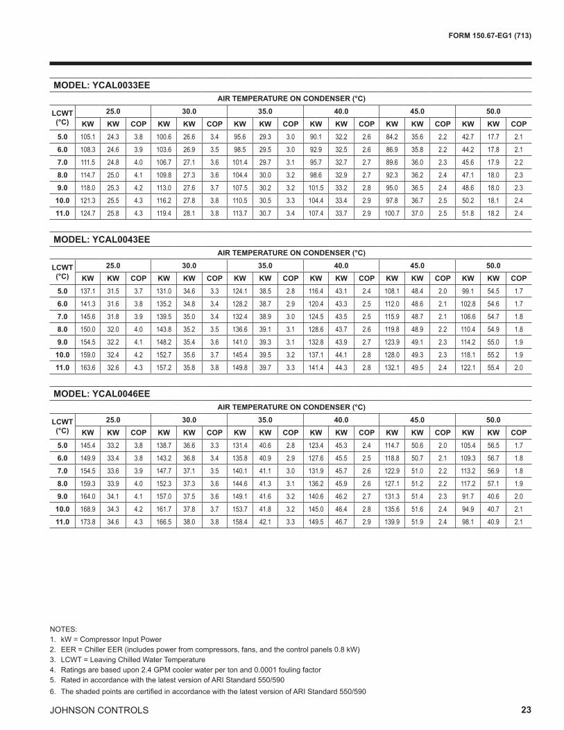
MODEL: YCAL0033EE AIR TEMPERATURE ON CONDENSER (°C)
LCWT(°C)
25.0 30.0 35.0 40.0 45.0 50.0KW KW COP KW KW COP KW KW COP KW KW COP KW KW COP KW KW COP
5.0 105.1 24.3 3.8 100.6 26.6 3.4 95.6 29.3 3.0 90.1 32.2 2.6 84.2 35.6 2.2 42.7 17.7 2.16.0 108.3 24.6 3.9 103.6 26.9 3.5 98.5 29.5 3.0 92.9 32.5 2.6 86.9 35.8 2.2 44.2 17.8 2.17.0 111.5 24.8 4.0 106.7 27.1 3.6 101.4 29.7 3.1 95.7 32.7 2.7 89.6 36.0 2.3 45.6 17.9 2.28.0 114.7 25.0 4.1 109.8 27.3 3.6 104.4 30.0 3.2 98.6 32.9 2.7 92.3 36.2 2.4 47.1 18.0 2.39.0 118.0 25.3 4.2 113.0 27.6 3.7 107.5 30.2 3.2 101.5 33.2 2.8 95.0 36.5 2.4 48.6 18.0 2.3
10.0 121.3 25.5 4.3 116.2 27.8 3.8 110.5 30.5 3.3 104.4 33.4 2.9 97.8 36.7 2.5 50.2 18.1 2.411.0 124.7 25.8 4.3 119.4 28.1 3.8 113.7 30.7 3.4 107.4 33.7 2.9 100.7 37.0 2.5 51.8 18.2 2.4
MODEL: YCAL0043EE AIR TEMPERATURE ON CONDENSER (°C)
LCWT(°C)
25.0 30.0 35.0 40.0 45.0 50.0KW KW COP KW KW COP KW KW COP KW KW COP KW KW COP KW KW COP
5.0 137.1 31.5 3.7 131.0 34.6 3.3 124.1 38.5 2.8 116.4 43.1 2.4 108.1 48.4 2.0 99.1 54.5 1.76.0 141.3 31.6 3.8 135.2 34.8 3.4 128.2 38.7 2.9 120.4 43.3 2.5 112.0 48.6 2.1 102.8 54.6 1.77.0 145.6 31.8 3.9 139.5 35.0 3.4 132.4 38.9 3.0 124.5 43.5 2.5 115.9 48.7 2.1 106.6 54.7 1.88.0 150.0 32.0 4.0 143.8 35.2 3.5 136.6 39.1 3.1 128.6 43.7 2.6 119.8 48.9 2.2 110.4 54.9 1.89.0 154.5 32.2 4.1 148.2 35.4 3.6 141.0 39.3 3.1 132.8 43.9 2.7 123.9 49.1 2.3 114.2 55.0 1.9
10.0 159.0 32.4 4.2 152.7 35.6 3.7 145.4 39.5 3.2 137.1 44.1 2.8 128.0 49.3 2.3 118.1 55.2 1.911.0 163.6 32.6 4.3 157.2 35.8 3.8 149.8 39.7 3.3 141.4 44.3 2.8 132.1 49.5 2.4 122.1 55.4 2.0
MODEL: YCAL0046EE AIR TEMPERATURE ON CONDENSER (°C)
LCWT(°C)
25.0 30.0 35.0 40.0 45.0 50.0KW KW COP KW KW COP KW KW COP KW KW COP KW KW COP KW KW COP
5.0 145.4 33.2 3.8 138.7 36.6 3.3 131.4 40.6 2.8 123.4 45.3 2.4 114.7 50.6 2.0 105.4 56.5 1.76.0 149.9 33.4 3.8 143.2 36.8 3.4 135.8 40.9 2.9 127.6 45.5 2.5 118.8 50.7 2.1 109.3 56.7 1.87.0 154.5 33.6 3.9 147.7 37.1 3.5 140.1 41.1 3.0 131.9 45.7 2.6 122.9 51.0 2.2 113.2 56.9 1.88.0 159.3 33.9 4.0 152.3 37.3 3.6 144.6 41.3 3.1 136.2 45.9 2.6 127.1 51.2 2.2 117.2 57.1 1.99.0 164.0 34.1 4.1 157.0 37.5 3.6 149.1 41.6 3.2 140.6 46.2 2.7 131.3 51.4 2.3 91.7 40.6 2.0
10.0 168.9 34.3 4.2 161.7 37.8 3.7 153.7 41.8 3.2 145.0 46.4 2.8 135.6 51.6 2.4 94.9 40.7 2.111.0 173.8 34.6 4.3 166.5 38.0 3.8 158.4 42.1 3.3 149.5 46.7 2.9 139.9 51.9 2.4 98.1 40.9 2.1
24
FORM 150.67-EG1 (713)
JOHNSON CONTROLS
NOTES:1. kW = Compressor Input Power2. EER = Chiller EER (includes power from compressors, fans, and the control panels 0.8 kW)3. LCWT = Leaving Chilled Water Temperature4. Ratings are based upon 2.4 GPM cooler water per ton and 0.0001 fouling factor5. Rated in accordance with the latest version of ARI Standard 550/5906. The shaded points are certified in accordance with the latest version of ARI Standard 550/590
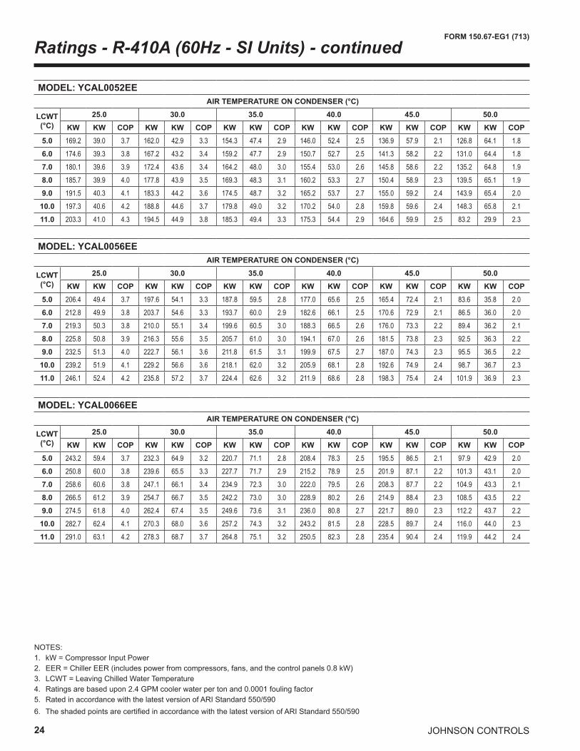
Ratings - R-410A (60Hz - SI Units) - continued
MODEL: YCAL0052EE AIR TEMPERATURE ON CONDENSER (°C)
LCWT(°C)
25.0 30.0 35.0 40.0 45.0 50.0KW KW COP KW KW COP KW KW COP KW KW COP KW KW COP KW KW COP
5.0 169.2 39.0 3.7 162.0 42.9 3.3 154.3 47.4 2.9 146.0 52.4 2.5 136.9 57.9 2.1 126.8 64.1 1.86.0 174.6 39.3 3.8 167.2 43.2 3.4 159.2 47.7 2.9 150.7 52.7 2.5 141.3 58.2 2.2 131.0 64.4 1.87.0 180.1 39.6 3.9 172.4 43.6 3.4 164.2 48.0 3.0 155.4 53.0 2.6 145.8 58.6 2.2 135.2 64.8 1.98.0 185.7 39.9 4.0 177.8 43.9 3.5 169.3 48.3 3.1 160.2 53.3 2.7 150.4 58.9 2.3 139.5 65.1 1.99.0 191.5 40.3 4.1 183.3 44.2 3.6 174.5 48.7 3.2 165.2 53.7 2.7 155.0 59.2 2.4 143.9 65.4 2.0
10.0 197.3 40.6 4.2 188.8 44.6 3.7 179.8 49.0 3.2 170.2 54.0 2.8 159.8 59.6 2.4 148.3 65.8 2.111.0 203.3 41.0 4.3 194.5 44.9 3.8 185.3 49.4 3.3 175.3 54.4 2.9 164.6 59.9 2.5 83.2 29.9 2.3
MODEL: YCAL0056EE AIR TEMPERATURE ON CONDENSER (°C)
LCWT(°C)
25.0 30.0 35.0 40.0 45.0 50.0KW KW COP KW KW COP KW KW COP KW KW COP KW KW COP KW KW COP
5.0 206.4 49.4 3.7 197.6 54.1 3.3 187.8 59.5 2.8 177.0 65.6 2.5 165.4 72.4 2.1 83.6 35.8 2.06.0 212.8 49.9 3.8 203.7 54.6 3.3 193.7 60.0 2.9 182.6 66.1 2.5 170.6 72.9 2.1 86.5 36.0 2.07.0 219.3 50.3 3.8 210.0 55.1 3.4 199.6 60.5 3.0 188.3 66.5 2.6 176.0 73.3 2.2 89.4 36.2 2.18.0 225.8 50.8 3.9 216.3 55.6 3.5 205.7 61.0 3.0 194.1 67.0 2.6 181.5 73.8 2.3 92.5 36.3 2.29.0 232.5 51.3 4.0 222.7 56.1 3.6 211.8 61.5 3.1 199.9 67.5 2.7 187.0 74.3 2.3 95.5 36.5 2.2
10.0 239.2 51.9 4.1 229.2 56.6 3.6 218.1 62.0 3.2 205.9 68.1 2.8 192.6 74.9 2.4 98.7 36.7 2.311.0 246.1 52.4 4.2 235.8 57.2 3.7 224.4 62.6 3.2 211.9 68.6 2.8 198.3 75.4 2.4 101.9 36.9 2.3
MODEL: YCAL0066EE AIR TEMPERATURE ON CONDENSER (°C)
LCWT(°C)
25.0 30.0 35.0 40.0 45.0 50.0KW KW COP KW KW COP KW KW COP KW KW COP KW KW COP KW KW COP
5.0 243.2 59.4 3.7 232.3 64.9 3.2 220.7 71.1 2.8 208.4 78.3 2.5 195.5 86.5 2.1 97.9 42.9 2.06.0 250.8 60.0 3.8 239.6 65.5 3.3 227.7 71.7 2.9 215.2 78.9 2.5 201.9 87.1 2.2 101.3 43.1 2.07.0 258.6 60.6 3.8 247.1 66.1 3.4 234.9 72.3 3.0 222.0 79.5 2.6 208.3 87.7 2.2 104.9 43.3 2.18.0 266.5 61.2 3.9 254.7 66.7 3.5 242.2 73.0 3.0 228.9 80.2 2.6 214.9 88.4 2.3 108.5 43.5 2.29.0 274.5 61.8 4.0 262.4 67.4 3.5 249.6 73.6 3.1 236.0 80.8 2.7 221.7 89.0 2.3 112.2 43.7 2.2
10.0 282.7 62.4 4.1 270.3 68.0 3.6 257.2 74.3 3.2 243.2 81.5 2.8 228.5 89.7 2.4 116.0 44.0 2.311.0 291.0 63.1 4.2 278.3 68.7 3.7 264.8 75.1 3.2 250.5 82.3 2.8 235.4 90.4 2.4 119.9 44.2 2.4
JOHNSON CONTROLS 25
FORM 150.67-EG1 (713)
INTENTIONALLY LEFT BLANK
26
FORM 150.67-EG1 (713)
JOHNSON CONTROLS
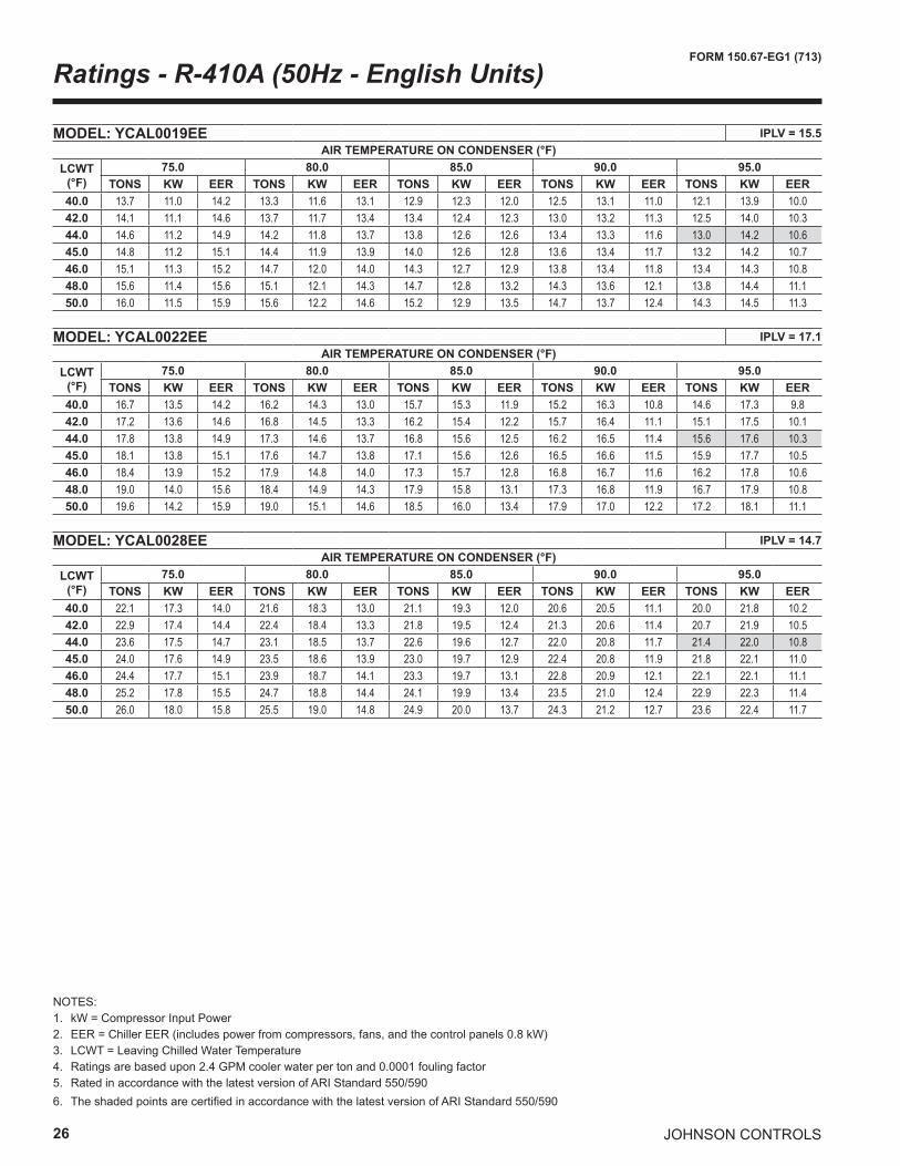
Ratings - R-410A (50Hz - English Units)
NOTES:1. kW = Compressor Input Power2. EER = Chiller EER (includes power from compressors, fans, and the control panels 0.8 kW)3. LCWT = Leaving Chilled Water Temperature4. Ratings are based upon 2.4 GPM cooler water per ton and 0.0001 fouling factor5. Rated in accordance with the latest version of ARI Standard 550/5906. The shaded points are certified in accordance with the latest version of ARI Standard 550/590
MODEL: YCAL0019EE IPLV = 15.5 AIR TEMPERATURE ON CONDENSER (°F)
LCWT(°F)
75.0 80.0 85.0 90.0 95.0TONS KW EER TONS KW EER TONS KW EER TONS KW EER TONS KW EER
40.0 13.7 11.0 14.2 13.3 11.6 13.1 12.9 12.3 12.0 12.5 13.1 11.0 12.1 13.9 10.042.0 14.1 11.1 14.6 13.7 11.7 13.4 13.4 12.4 12.3 13.0 13.2 11.3 12.5 14.0 10.344.0 14.6 11.2 14.9 14.2 11.8 13.7 13.8 12.6 12.6 13.4 13.3 11.6 13.0 14.2 10.645.0 14.8 11.2 15.1 14.4 11.9 13.9 14.0 12.6 12.8 13.6 13.4 11.7 13.2 14.2 10.746.0 15.1 11.3 15.2 14.7 12.0 14.0 14.3 12.7 12.9 13.8 13.4 11.8 13.4 14.3 10.848.0 15.6 11.4 15.6 15.1 12.1 14.3 14.7 12.8 13.2 14.3 13.6 12.1 13.8 14.4 11.150.0 16.0 11.5 15.9 15.6 12.2 14.6 15.2 12.9 13.5 14.7 13.7 12.4 14.3 14.5 11.3
MODEL: YCAL0022EE IPLV = 17.1 AIR TEMPERATURE ON CONDENSER (°F)
LCWT(°F)
75.0 80.0 85.0 90.0 95.0TONS KW EER TONS KW EER TONS KW EER TONS KW EER TONS KW EER
40.0 16.7 13.5 14.2 16.2 14.3 13.0 15.7 15.3 11.9 15.2 16.3 10.8 14.6 17.3 9.842.0 17.2 13.6 14.6 16.8 14.5 13.3 16.2 15.4 12.2 15.7 16.4 11.1 15.1 17.5 10.144.0 17.8 13.8 14.9 17.3 14.6 13.7 16.8 15.6 12.5 16.2 16.5 11.4 15.6 17.6 10.345.0 18.1 13.8 15.1 17.6 14.7 13.8 17.1 15.6 12.6 16.5 16.6 11.5 15.9 17.7 10.546.0 18.4 13.9 15.2 17.9 14.8 14.0 17.3 15.7 12.8 16.8 16.7 11.6 16.2 17.8 10.648.0 19.0 14.0 15.6 18.4 14.9 14.3 17.9 15.8 13.1 17.3 16.8 11.9 16.7 17.9 10.850.0 19.6 14.2 15.9 19.0 15.1 14.6 18.5 16.0 13.4 17.9 17.0 12.2 17.2 18.1 11.1
MODEL: YCAL0028EE IPLV = 14.7 AIR TEMPERATURE ON CONDENSER (°F)
LCWT(°F)
75.0 80.0 85.0 90.0 95.0TONS KW EER TONS KW EER TONS KW EER TONS KW EER TONS KW EER
40.0 22.1 17.3 14.0 21.6 18.3 13.0 21.1 19.3 12.0 20.6 20.5 11.1 20.0 21.8 10.242.0 22.9 17.4 14.4 22.4 18.4 13.3 21.8 19.5 12.4 21.3 20.6 11.4 20.7 21.9 10.544.0 23.6 17.5 14.7 23.1 18.5 13.7 22.6 19.6 12.7 22.0 20.8 11.7 21.4 22.0 10.845.0 24.0 17.6 14.9 23.5 18.6 13.9 23.0 19.7 12.9 22.4 20.8 11.9 21.8 22.1 11.046.0 24.4 17.7 15.1 23.9 18.7 14.1 23.3 19.7 13.1 22.8 20.9 12.1 22.1 22.1 11.148.0 25.2 17.8 15.5 24.7 18.8 14.4 24.1 19.9 13.4 23.5 21.0 12.4 22.9 22.3 11.450.0 26.0 18.0 15.8 25.5 19.0 14.8 24.9 20.0 13.7 24.3 21.2 12.7 23.6 22.4 11.7
JOHNSON CONTROLS 27
FORM 150.67-EG1 (713)
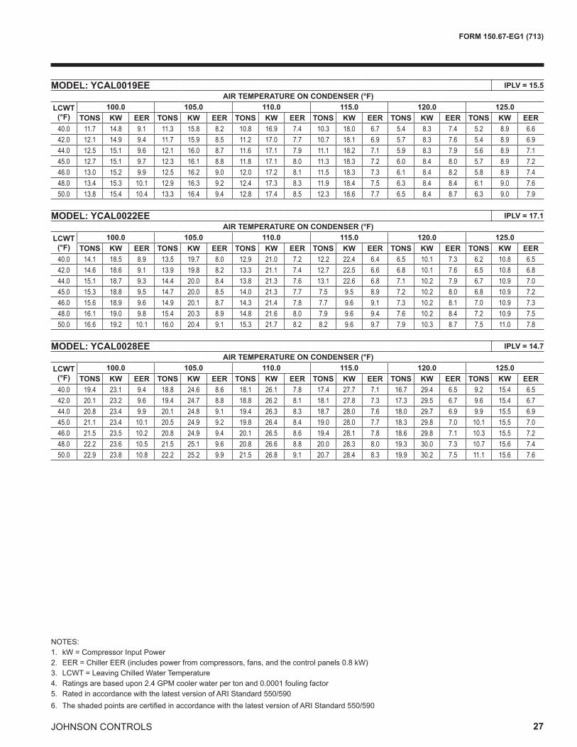
NOTES:1. kW = Compressor Input Power2. EER = Chiller EER (includes power from compressors, fans, and the control panels 0.8 kW)3. LCWT = Leaving Chilled Water Temperature4. Ratings are based upon 2.4 GPM cooler water per ton and 0.0001 fouling factor5. Rated in accordance with the latest version of ARI Standard 550/5906. The shaded points are certified in accordance with the latest version of ARI Standard 550/590
MODEL: YCAL0019EE IPLV = 15.5 AIR TEMPERATURE ON CONDENSER (°F)
LCWT(°F)
100.0 105.0 110.0 115.0 120.0 125.0TONS KW EER TONS KW EER TONS KW EER TONS KW EER TONS KW EER TONS KW EER
40.0 11.7 14.8 9.1 11.3 15.8 8.2 10.8 16.9 7.4 10.3 18.0 6.7 5.4 8.3 7.4 5.2 8.9 6.642.0 12.1 14.9 9.4 11.7 15.9 8.5 11.2 17.0 7.7 10.7 18.1 6.9 5.7 8.3 7.6 5.4 8.9 6.944.0 12.5 15.1 9.6 12.1 16.0 8.7 11.6 17.1 7.9 11.1 18.2 7.1 5.9 8.3 7.9 5.6 8.9 7.145.0 12.7 15.1 9.7 12.3 16.1 8.8 11.8 17.1 8.0 11.3 18.3 7.2 6.0 8.4 8.0 5.7 8.9 7.246.0 13.0 15.2 9.9 12.5 16.2 9.0 12.0 17.2 8.1 11.5 18.3 7.3 6.1 8.4 8.2 5.8 8.9 7.448.0 13.4 15.3 10.1 12.9 16.3 9.2 12.4 17.3 8.3 11.9 18.4 7.5 6.3 8.4 8.4 6.1 9.0 7.650.0 13.8 15.4 10.4 13.3 16.4 9.4 12.8 17.4 8.5 12.3 18.6 7.7 6.5 8.4 8.7 6.3 9.0 7.9
MODEL: YCAL0022EE IPLV = 17.1 AIR TEMPERATURE ON CONDENSER (°F)
LCWT(°F)
100.0 105.0 110.0 115.0 120.0 125.0TONS KW EER TONS KW EER TONS KW EER TONS KW EER TONS KW EER TONS KW EER
40.0 14.1 18.5 8.9 13.5 19.7 8.0 12.9 21.0 7.2 12.2 22.4 6.4 6.5 10.1 7.3 6.2 10.8 6.542.0 14.6 18.6 9.1 13.9 19.8 8.2 13.3 21.1 7.4 12.7 22.5 6.6 6.8 10.1 7.6 6.5 10.8 6.844.0 15.1 18.7 9.3 14.4 20.0 8.4 13.8 21.3 7.6 13.1 22.6 6.8 7.1 10.2 7.9 6.7 10.9 7.045.0 15.3 18.8 9.5 14.7 20.0 8.5 14.0 21.3 7.7 7.5 9.5 8.9 7.2 10.2 8.0 6.8 10.9 7.246.0 15.6 18.9 9.6 14.9 20.1 8.7 14.3 21.4 7.8 7.7 9.6 9.1 7.3 10.2 8.1 7.0 10.9 7.348.0 16.1 19.0 9.8 15.4 20.3 8.9 14.8 21.6 8.0 7.9 9.6 9.4 7.6 10.2 8.4 7.2 10.9 7.550.0 16.6 19.2 10.1 16.0 20.4 9.1 15.3 21.7 8.2 8.2 9.6 9.7 7.9 10.3 8.7 7.5 11.0 7.8
MODEL: YCAL0028EE IPLV = 14.7 AIR TEMPERATURE ON CONDENSER (°F)
LCWT(°F)
100.0 105.0 110.0 115.0 120.0 125.0TONS KW EER TONS KW EER TONS KW EER TONS KW EER TONS KW EER TONS KW EER
40.0 19.4 23.1 9.4 18.8 24.6 8.6 18.1 26.1 7.8 17.4 27.7 7.1 16.7 29.4 6.5 9.2 15.4 6.542.0 20.1 23.2 9.6 19.4 24.7 8.8 18.8 26.2 8.1 18.1 27.8 7.3 17.3 29.5 6.7 9.6 15.4 6.744.0 20.8 23.4 9.9 20.1 24.8 9.1 19.4 26.3 8.3 18.7 28.0 7.6 18.0 29.7 6.9 9.9 15.5 6.945.0 21.1 23.4 10.1 20.5 24.9 9.2 19.8 26.4 8.4 19.0 28.0 7.7 18.3 29.8 7.0 10.1 15.5 7.046.0 21.5 23.5 10.2 20.8 24.9 9.4 20.1 26.5 8.6 19.4 28.1 7.8 18.6 29.8 7.1 10.3 15.5 7.248.0 22.2 23.6 10.5 21.5 25.1 9.6 20.8 26.6 8.8 20.0 28.3 8.0 19.3 30.0 7.3 10.7 15.6 7.450.0 22.9 23.8 10.8 22.2 25.2 9.9 21.5 26.8 9.1 20.7 28.4 8.3 19.9 30.2 7.5 11.1 15.6 7.6
28
FORM 150.67-EG1 (713)
JOHNSON CONTROLS
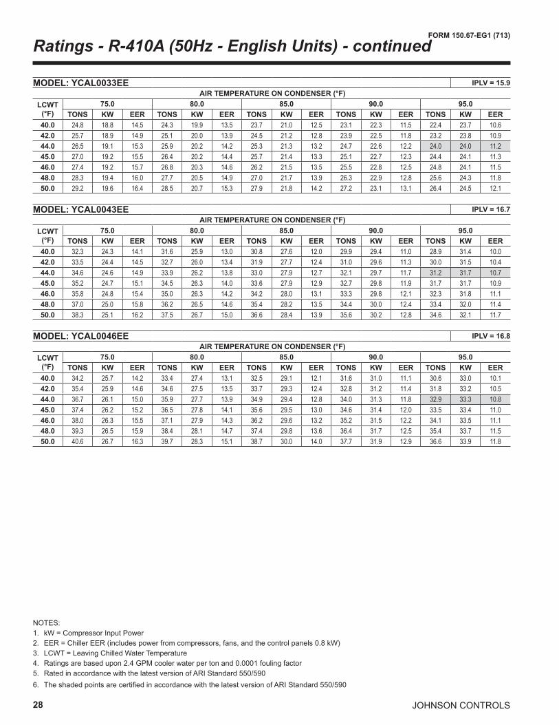
Ratings - R-410A (50Hz - English Units) - continued
NOTES:1. kW = Compressor Input Power2. EER = Chiller EER (includes power from compressors, fans, and the control panels 0.8 kW)3. LCWT = Leaving Chilled Water Temperature4. Ratings are based upon 2.4 GPM cooler water per ton and 0.0001 fouling factor5. Rated in accordance with the latest version of ARI Standard 550/5906. The shaded points are certified in accordance with the latest version of ARI Standard 550/590
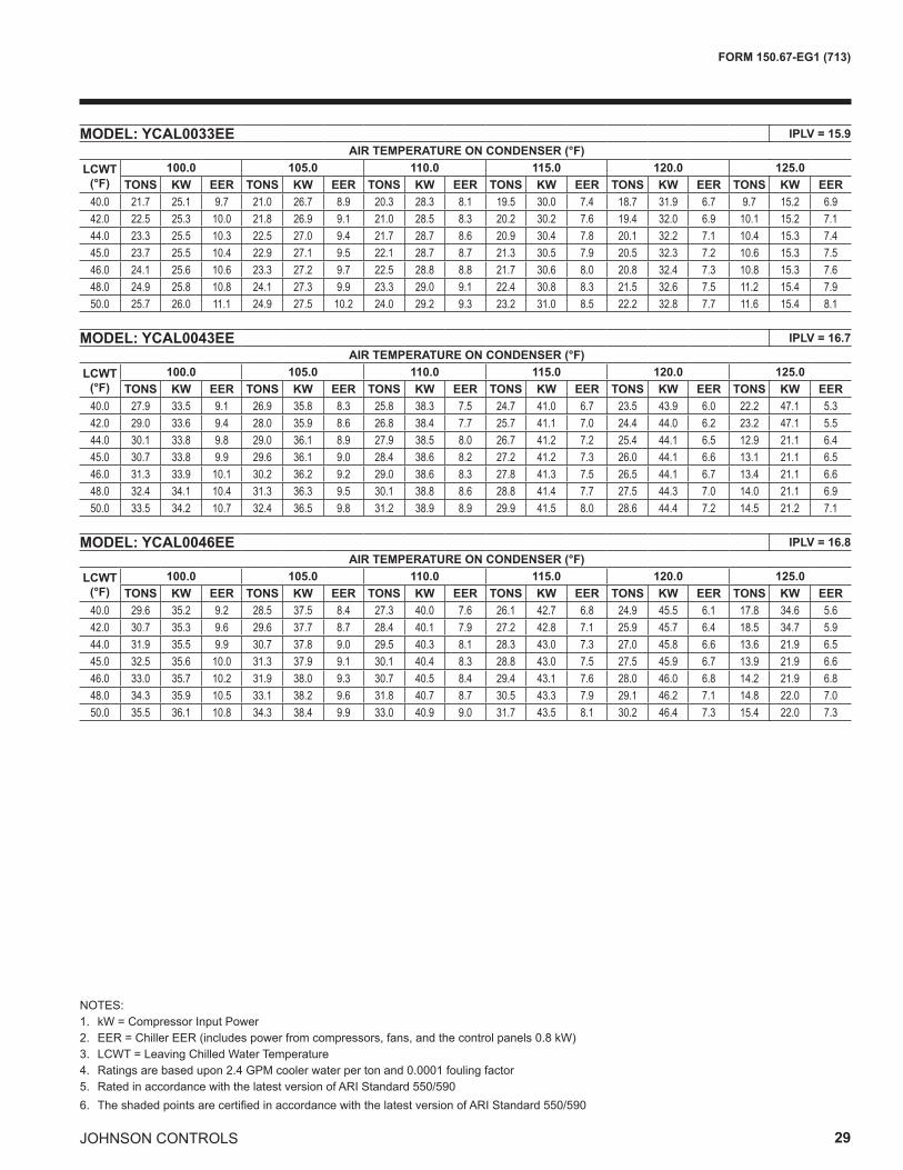
MODEL: YCAL0033EE IPLV = 15.9 AIR TEMPERATURE ON CONDENSER (°F)
LCWT(°F)
75.0 80.0 85.0 90.0 95.0TONS KW EER TONS KW EER TONS KW EER TONS KW EER TONS KW EER
40.0 24.8 18.8 14.5 24.3 19.9 13.5 23.7 21.0 12.5 23.1 22.3 11.5 22.4 23.7 10.642.0 25.7 18.9 14.9 25.1 20.0 13.9 24.5 21.2 12.8 23.9 22.5 11.8 23.2 23.8 10.944.0 26.5 19.1 15.3 25.9 20.2 14.2 25.3 21.3 13.2 24.7 22.6 12.2 24.0 24.0 11.245.0 27.0 19.2 15.5 26.4 20.2 14.4 25.7 21.4 13.3 25.1 22.7 12.3 24.4 24.1 11.346.0 27.4 19.2 15.7 26.8 20.3 14.6 26.2 21.5 13.5 25.5 22.8 12.5 24.8 24.1 11.548.0 28.3 19.4 16.0 27.7 20.5 14.9 27.0 21.7 13.9 26.3 22.9 12.8 25.6 24.3 11.850.0 29.2 19.6 16.4 28.5 20.7 15.3 27.9 21.8 14.2 27.2 23.1 13.1 26.4 24.5 12.1
MODEL: YCAL0043EE IPLV = 16.7 AIR TEMPERATURE ON CONDENSER (°F)
LCWT(°F)
75.0 80.0 85.0 90.0 95.0TONS KW EER TONS KW EER TONS KW EER TONS KW EER TONS KW EER
40.0 32.3 24.3 14.1 31.6 25.9 13.0 30.8 27.6 12.0 29.9 29.4 11.0 28.9 31.4 10.042.0 33.5 24.4 14.5 32.7 26.0 13.4 31.9 27.7 12.4 31.0 29.6 11.3 30.0 31.5 10.444.0 34.6 24.6 14.9 33.9 26.2 13.8 33.0 27.9 12.7 32.1 29.7 11.7 31.2 31.7 10.745.0 35.2 24.7 15.1 34.5 26.3 14.0 33.6 27.9 12.9 32.7 29.8 11.9 31.7 31.7 10.946.0 35.8 24.8 15.4 35.0 26.3 14.2 34.2 28.0 13.1 33.3 29.8 12.1 32.3 31.8 11.148.0 37.0 25.0 15.8 36.2 26.5 14.6 35.4 28.2 13.5 34.4 30.0 12.4 33.4 32.0 11.450.0 38.3 25.1 16.2 37.5 26.7 15.0 36.6 28.4 13.9 35.6 30.2 12.8 34.6 32.1 11.7
MODEL: YCAL0046EE IPLV = 16.8 AIR TEMPERATURE ON CONDENSER (°F)
LCWT(°F)
75.0 80.0 85.0 90.0 95.0TONS KW EER TONS KW EER TONS KW EER TONS KW EER TONS KW EER
40.0 34.2 25.7 14.2 33.4 27.4 13.1 32.5 29.1 12.1 31.6 31.0 11.1 30.6 33.0 10.142.0 35.4 25.9 14.6 34.6 27.5 13.5 33.7 29.3 12.4 32.8 31.2 11.4 31.8 33.2 10.544.0 36.7 26.1 15.0 35.9 27.7 13.9 34.9 29.4 12.8 34.0 31.3 11.8 32.9 33.3 10.845.0 37.4 26.2 15.2 36.5 27.8 14.1 35.6 29.5 13.0 34.6 31.4 12.0 33.5 33.4 11.046.0 38.0 26.3 15.5 37.1 27.9 14.3 36.2 29.6 13.2 35.2 31.5 12.2 34.1 33.5 11.148.0 39.3 26.5 15.9 38.4 28.1 14.7 37.4 29.8 13.6 36.4 31.7 12.5 35.4 33.7 11.550.0 40.6 26.7 16.3 39.7 28.3 15.1 38.7 30.0 14.0 37.7 31.9 12.9 36.6 33.9 11.8
JOHNSON CONTROLS 29
FORM 150.67-EG1 (713)
NOTES:1. kW = Compressor Input Power2. EER = Chiller EER (includes power from compressors, fans, and the control panels 0.8 kW)3. LCWT = Leaving Chilled Water Temperature4. Ratings are based upon 2.4 GPM cooler water per ton and 0.0001 fouling factor5. Rated in accordance with the latest version of ARI Standard 550/5906. The shaded points are certified in accordance with the latest version of ARI Standard 550/590
MODEL: YCAL0033EE IPLV = 15.9 AIR TEMPERATURE ON CONDENSER (°F)
LCWT(°F)
100.0 105.0 110.0 115.0 120.0 125.0TONS KW EER TONS KW EER TONS KW EER TONS KW EER TONS KW EER TONS KW EER
40.0 21.7 25.1 9.7 21.0 26.7 8.9 20.3 28.3 8.1 19.5 30.0 7.4 18.7 31.9 6.7 9.7 15.2 6.942.0 22.5 25.3 10.0 21.8 26.9 9.1 21.0 28.5 8.3 20.2 30.2 7.6 19.4 32.0 6.9 10.1 15.2 7.144.0 23.3 25.5 10.3 22.5 27.0 9.4 21.7 28.7 8.6 20.9 30.4 7.8 20.1 32.2 7.1 10.4 15.3 7.445.0 23.7 25.5 10.4 22.9 27.1 9.5 22.1 28.7 8.7 21.3 30.5 7.9 20.5 32.3 7.2 10.6 15.3 7.546.0 24.1 25.6 10.6 23.3 27.2 9.7 22.5 28.8 8.8 21.7 30.6 8.0 20.8 32.4 7.3 10.8 15.3 7.648.0 24.9 25.8 10.8 24.1 27.3 9.9 23.3 29.0 9.1 22.4 30.8 8.3 21.5 32.6 7.5 11.2 15.4 7.950.0 25.7 26.0 11.1 24.9 27.5 10.2 24.0 29.2 9.3 23.2 31.0 8.5 22.2 32.8 7.7 11.6 15.4 8.1
MODEL: YCAL0043EE IPLV = 16.7 AIR TEMPERATURE ON CONDENSER (°F)
LCWT(°F)
100.0 105.0 110.0 115.0 120.0 125.0TONS KW EER TONS KW EER TONS KW EER TONS KW EER TONS KW EER TONS KW EER
40.0 27.9 33.5 9.1 26.9 35.8 8.3 25.8 38.3 7.5 24.7 41.0 6.7 23.5 43.9 6.0 22.2 47.1 5.342.0 29.0 33.6 9.4 28.0 35.9 8.6 26.8 38.4 7.7 25.7 41.1 7.0 24.4 44.0 6.2 23.2 47.1 5.544.0 30.1 33.8 9.8 29.0 36.1 8.9 27.9 38.5 8.0 26.7 41.2 7.2 25.4 44.1 6.5 12.9 21.1 6.445.0 30.7 33.8 9.9 29.6 36.1 9.0 28.4 38.6 8.2 27.2 41.2 7.3 26.0 44.1 6.6 13.1 21.1 6.546.0 31.3 33.9 10.1 30.2 36.2 9.2 29.0 38.6 8.3 27.8 41.3 7.5 26.5 44.1 6.7 13.4 21.1 6.648.0 32.4 34.1 10.4 31.3 36.3 9.5 30.1 38.8 8.6 28.8 41.4 7.7 27.5 44.3 7.0 14.0 21.1 6.950.0 33.5 34.2 10.7 32.4 36.5 9.8 31.2 38.9 8.9 29.9 41.5 8.0 28.6 44.4 7.2 14.5 21.2 7.1
MODEL: YCAL0046EE IPLV = 16.8 AIR TEMPERATURE ON CONDENSER (°F)
LCWT(°F)
100.0 105.0 110.0 115.0 120.0 125.0TONS KW EER TONS KW EER TONS KW EER TONS KW EER TONS KW EER TONS KW EER
40.0 29.6 35.2 9.2 28.5 37.5 8.4 27.3 40.0 7.6 26.1 42.7 6.8 24.9 45.5 6.1 17.8 34.6 5.642.0 30.7 35.3 9.6 29.6 37.7 8.7 28.4 40.1 7.9 27.2 42.8 7.1 25.9 45.7 6.4 18.5 34.7 5.944.0 31.9 35.5 9.9 30.7 37.8 9.0 29.5 40.3 8.1 28.3 43.0 7.3 27.0 45.8 6.6 13.6 21.9 6.545.0 32.5 35.6 10.0 31.3 37.9 9.1 30.1 40.4 8.3 28.8 43.0 7.5 27.5 45.9 6.7 13.9 21.9 6.646.0 33.0 35.7 10.2 31.9 38.0 9.3 30.7 40.5 8.4 29.4 43.1 7.6 28.0 46.0 6.8 14.2 21.9 6.848.0 34.3 35.9 10.5 33.1 38.2 9.6 31.8 40.7 8.7 30.5 43.3 7.9 29.1 46.2 7.1 14.8 22.0 7.050.0 35.5 36.1 10.8 34.3 38.4 9.9 33.0 40.9 9.0 31.7 43.5 8.1 30.2 46.4 7.3 15.4 22.0 7.3

30
FORM 150.67-EG1 (713)
JOHNSON CONTROLS
Ratings - R-410A (50Hz - English Units) - continued
NOTES:1. kW = Compressor Input Power2. EER = Chiller EER (includes power from compressors, fans, and the control panels 0.8 kW)3. LCWT = Leaving Chilled Water Temperature4. Ratings are based upon 2.4 GPM cooler water per ton and 0.0001 fouling factor5. Rated in accordance with the latest version of ARI Standard 550/5906. The shaded points are certified in accordance with the latest version of ARI Standard 550/590
MODEL: YCAL0052EE IPLV = 16.2 AIR TEMPERATURE ON CONDENSER (°F)
LCWT(°F)
75.0 80.0 85.0 90.0 95.0TONS KW EER TONS KW EER TONS KW EER TONS KW EER TONS KW EER
40.0 39.7 29.8 14.1 38.9 31.6 13.2 38.0 33.5 12.2 37.0 35.5 11.3 36.0 37.7 10.442.0 41.1 30.0 14.5 40.2 31.8 13.5 39.3 33.6 12.6 38.4 35.7 11.6 37.3 37.9 10.744.0 42.5 30.3 14.9 41.6 32.0 13.9 40.7 33.9 12.9 39.7 35.9 12.0 38.7 38.1 11.145.0 43.2 30.4 15.1 42.3 32.1 14.1 41.4 34.0 13.1 40.4 36.0 12.2 39.3 38.2 11.246.0 43.9 30.5 15.3 43.0 32.2 14.3 42.1 34.1 13.3 41.1 36.1 12.3 40.0 38.3 11.448.0 45.4 30.8 15.7 44.5 32.5 14.7 43.5 34.3 13.7 42.5 36.3 12.7 41.4 38.5 11.750.0 46.9 31.1 16.1 46.0 32.7 15.1 45.0 34.6 14.0 43.9 36.6 13.0 42.8 38.8 12.0
MODEL: YCAL0056EE IPLV = 16.2 AIR TEMPERATURE ON CONDENSER (°F)
LCWT(°F)
75.0 80.0 85.0 90.0 95.0TONS KW EER TONS KW EER TONS KW EER TONS KW EER TONS KW EER
40.0 48.7 38.1 13.9 47.6 40.3 12.9 46.5 42.8 12.0 45.3 45.4 11.0 44.0 48.2 10.242.0 50.3 38.4 14.3 49.3 40.6 13.3 48.1 43.1 12.3 46.9 45.7 11.4 45.6 48.5 10.444.0 52.1 38.7 14.7 50.9 40.9 13.6 49.8 43.4 12.6 48.5 46.0 11.7 47.2 48.8 10.745.0 52.9 38.9 14.9 51.8 41.1 13.8 50.6 43.5 12.8 49.3 46.2 11.8 48.0 49.0 10.946.0 53.8 39.0 15.0 52.7 41.3 14.0 51.4 43.7 13.0 50.2 46.3 12.0 48.8 49.1 11.048.0 55.6 39.4 15.4 54.4 41.6 14.3 53.2 44.1 13.3 51.8 46.7 12.3 50.4 49.5 11.350.0 57.4 39.8 15.8 56.2 42.0 14.7 54.9 44.4 13.6 53.6 47.0 12.6 52.1 49.9 11.6
MODEL: YCAL0066EE IPLV = 0.0 AIR TEMPERATURE ON CONDENSER (°F)
LCWT(°F)
75.0 80.0 85.0 90.0 95.0TONS KW EER TONS KW EER TONS KW EER TONS KW EER TONS KW EER
40.0 57.7 46.6 13.7 56.3 49.2 12.7 54.9 51.9 11.8 53.4 54.9 10.9 51.8 58.2 10.042.0 59.7 47.1 14.1 58.3 49.6 13.1 56.8 52.4 12.1 55.3 55.4 11.2 53.7 58.6 10.344.0 61.8 47.5 14.4 60.3 50.1 13.4 58.8 52.8 12.4 57.2 55.8 11.5 0.0 0.0 0.045.0 62.8 47.7 14.6 61.3 50.3 13.6 59.8 53.1 12.6 58.2 56.1 11.7 56.6 59.3 10.746.0 63.9 48.0 14.8 62.4 50.5 13.8 60.8 53.3 12.8 59.2 56.3 11.8 57.5 59.5 10.948.0 66.0 48.5 15.1 64.5 51.0 14.1 62.9 53.8 13.1 61.2 56.8 12.1 59.5 60.0 11.250.0 68.2 49.0 15.5 66.6 51.5 14.4 65.0 54.3 13.4 63.3 57.3 12.4 61.5 60.6 11.5

JOHNSON CONTROLS 31
FORM 150.67-EG1 (713)
NOTES:1. kW = Compressor Input Power2. EER = Chiller EER (includes power from compressors, fans, and the control panels 0.8 kW)3. LCWT = Leaving Chilled Water Temperature4. Ratings are based upon 2.4 GPM cooler water per ton and 0.0001 fouling factor5. Rated in accordance with the latest version of ARI Standard 550/5906. The shaded points are certified in accordance with the latest version of ARI Standard 550/590
MODEL: YCAL0052EE IPLV = 16.2 AIR TEMPERATURE ON CONDENSER (°F)
LCWT(°F)
100.0 105.0 110.0 115.0 120.0 125.0TONS KW EER TONS KW EER TONS KW EER TONS KW EER TONS KW EER TONS KW EER
40.0 35.0 40.0 9.6 33.9 42.5 8.8 32.7 45.2 8.0 31.5 48.0 7.3 30.2 50.9 6.6 15.4 24.5 6.542.0 36.3 40.2 9.9 35.1 42.7 9.0 34.0 45.4 8.3 32.7 48.2 7.5 31.4 51.2 6.8 16.0 24.6 6.744.0 37.6 40.4 10.2 36.4 43.0 9.3 35.2 45.6 8.5 33.9 48.5 7.8 32.6 51.4 7.1 16.6 24.6 7.045.0 38.2 40.5 10.3 37.0 43.1 9.5 35.8 45.7 8.7 34.5 48.6 7.9 33.2 51.6 7.2 16.9 24.7 7.146.0 38.9 40.7 10.5 37.7 43.2 9.6 36.4 45.9 8.8 35.1 48.7 8.0 33.8 51.7 7.3 17.3 24.7 7.248.0 40.2 40.9 10.8 39.0 43.4 9.9 37.7 46.1 9.1 36.4 48.9 8.3 35.0 52.0 7.5 17.9 24.8 7.550.0 41.6 41.1 11.1 40.3 43.6 10.2 39.0 46.3 9.3 37.7 49.2 8.5 36.2 52.2 7.7 18.6 24.9 7.8
MODEL: YCAL0056EE IPLV = 16.2 AIR TEMPERATURE ON CONDENSER (°F)
LCWT(°F)
100.0 105.0 110.0 115.0 120.0 125.0TONS KW EER TONS KW EER TONS KW EER TONS KW EER TONS KW EER TONS KW EER
40.0 42.7 51.1 9.3 41.3 54.3 8.5 39.9 57.6 7.8 38.3 61.1 7.1 36.7 64.8 6.4 18.9 30.7 6.642.0 44.2 51.5 9.6 42.8 54.6 8.8 41.3 58.0 8.0 39.7 61.5 7.3 38.1 65.2 6.6 19.7 30.8 6.844.0 45.8 51.8 9.9 44.3 55.0 9.0 42.8 58.4 8.2 41.2 61.9 7.5 39.5 65.6 6.8 20.4 30.9 7.045.0 46.6 52.0 10.0 45.1 55.2 9.2 43.5 58.5 8.4 41.9 62.1 7.6 40.2 65.8 6.9 20.8 31.0 7.246.0 47.3 52.2 10.1 45.8 55.4 9.3 44.3 58.7 8.5 42.6 62.3 7.7 40.9 66.1 7.0 21.2 31.1 7.348.0 49.0 52.5 10.4 47.4 55.7 9.5 45.8 59.1 8.7 44.1 62.7 7.9 22.9 29.4 8.3 22.0 31.2 7.550.0 50.6 52.9 10.7 49.0 56.1 9.8 47.3 59.5 9.0 45.6 63.1 8.2 23.8 29.5 8.6 22.8 31.3 7.8
MODEL: YCAL0066EE IPLV = 0.0 AIR TEMPERATURE ON CONDENSER (°F)
LCWT(°F)
100.0 105.0 110.0 115.0 120.0 125.0TONS KW EER TONS KW EER TONS KW EER TONS KW EER TONS KW EER TONS KW EER
40.0 50.2 61.6 9.2 48.6 65.4 8.4 46.9 69.4 7.7 45.1 73.7 7.0 43.3 78.4 6.3 22.2 37.1 6.542.0 52.1 62.1 9.5 50.4 65.9 8.7 48.6 69.9 7.9 46.8 74.2 7.2 45.0 78.9 6.5 23.0 37.2 6.744.0 53.9 62.6 9.7 52.2 66.3 8.9 50.4 70.4 8.1 48.6 74.7 7.4 34.8 53.5 7.3 24.0 37.4 7.045.0 54.9 62.8 9.9 53.1 66.6 9.0 51.3 70.6 8.3 49.5 75.0 7.5 35.5 53.6 7.4 24.4 37.5 7.146.0 55.8 63.1 10.0 54.1 66.8 9.2 52.2 70.9 8.4 50.3 75.3 7.6 36.1 53.8 7.5 24.9 37.5 7.248.0 57.8 63.6 10.3 55.9 67.4 9.4 54.0 71.4 8.6 52.1 75.8 7.8 37.5 54.1 7.8 25.8 37.7 7.550.0 59.7 64.1 10.5 57.8 67.9 9.7 55.9 72.0 8.8 53.9 76.4 8.1 38.9 54.4 8.0 26.8 37.8 7.7
32
FORM 150.67-EG1 (713)
JOHNSON CONTROLS
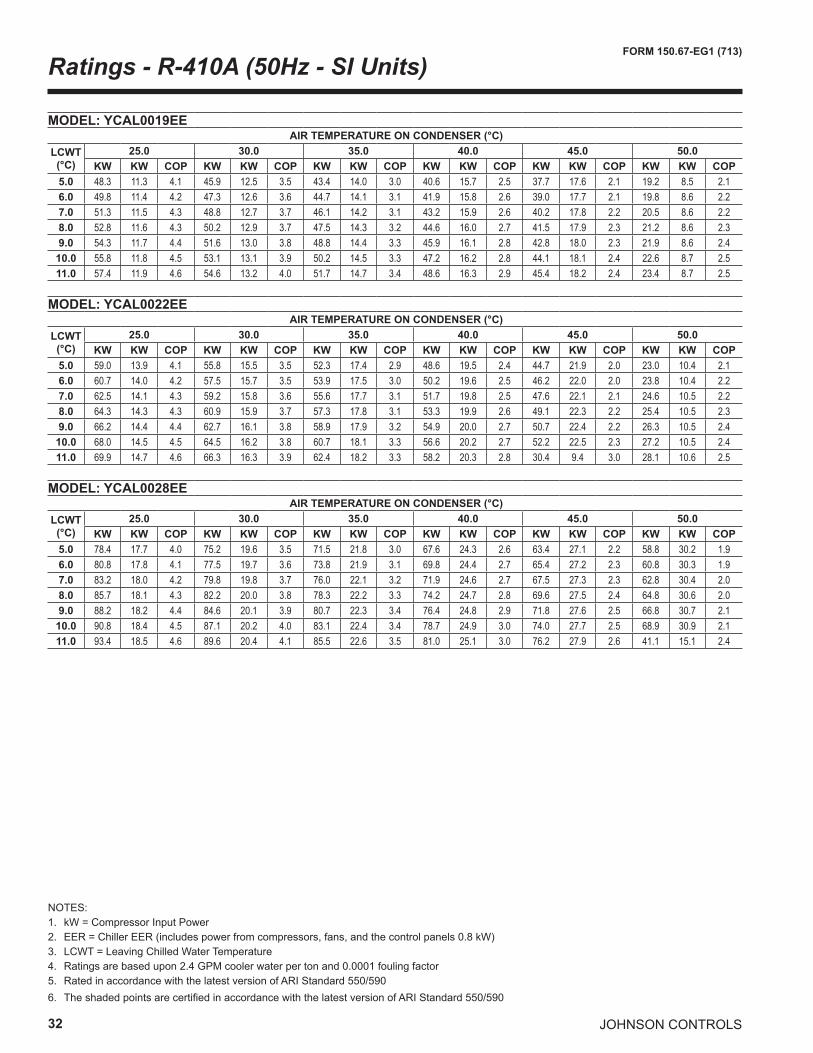
NOTES:1. kW = Compressor Input Power2. EER = Chiller EER (includes power from compressors, fans, and the control panels 0.8 kW)3. LCWT = Leaving Chilled Water Temperature4. Ratings are based upon 2.4 GPM cooler water per ton and 0.0001 fouling factor5. Rated in accordance with the latest version of ARI Standard 550/5906. The shaded points are certified in accordance with the latest version of ARI Standard 550/590
Ratings - R-410A (50Hz - SI Units)
MODEL: YCAL0019EE AIR TEMPERATURE ON CONDENSER (°C)
LCWT(°C)
25.0 30.0 35.0 40.0 45.0 50.0KW KW COP KW KW COP KW KW COP KW KW COP KW KW COP KW KW COP
5.0 48.3 11.3 4.1 45.9 12.5 3.5 43.4 14.0 3.0 40.6 15.7 2.5 37.7 17.6 2.1 19.2 8.5 2.16.0 49.8 11.4 4.2 47.3 12.6 3.6 44.7 14.1 3.1 41.9 15.8 2.6 39.0 17.7 2.1 19.8 8.6 2.27.0 51.3 11.5 4.3 48.8 12.7 3.7 46.1 14.2 3.1 43.2 15.9 2.6 40.2 17.8 2.2 20.5 8.6 2.28.0 52.8 11.6 4.3 50.2 12.9 3.7 47.5 14.3 3.2 44.6 16.0 2.7 41.5 17.9 2.3 21.2 8.6 2.39.0 54.3 11.7 4.4 51.6 13.0 3.8 48.8 14.4 3.3 45.9 16.1 2.8 42.8 18.0 2.3 21.9 8.6 2.4
10.0 55.8 11.8 4.5 53.1 13.1 3.9 50.2 14.5 3.3 47.2 16.2 2.8 44.1 18.1 2.4 22.6 8.7 2.511.0 57.4 11.9 4.6 54.6 13.2 4.0 51.7 14.7 3.4 48.6 16.3 2.9 45.4 18.2 2.4 23.4 8.7 2.5
MODEL: YCAL0022EE AIR TEMPERATURE ON CONDENSER (°C)
LCWT(°C)
25.0 30.0 35.0 40.0 45.0 50.0KW KW COP KW KW COP KW KW COP KW KW COP KW KW COP KW KW COP
5.0 59.0 13.9 4.1 55.8 15.5 3.5 52.3 17.4 2.9 48.6 19.5 2.4 44.7 21.9 2.0 23.0 10.4 2.16.0 60.7 14.0 4.2 57.5 15.7 3.5 53.9 17.5 3.0 50.2 19.6 2.5 46.2 22.0 2.0 23.8 10.4 2.27.0 62.5 14.1 4.3 59.2 15.8 3.6 55.6 17.7 3.1 51.7 19.8 2.5 47.6 22.1 2.1 24.6 10.5 2.28.0 64.3 14.3 4.3 60.9 15.9 3.7 57.3 17.8 3.1 53.3 19.9 2.6 49.1 22.3 2.2 25.4 10.5 2.39.0 66.2 14.4 4.4 62.7 16.1 3.8 58.9 17.9 3.2 54.9 20.0 2.7 50.7 22.4 2.2 26.3 10.5 2.4
10.0 68.0 14.5 4.5 64.5 16.2 3.8 60.7 18.1 3.3 56.6 20.2 2.7 52.2 22.5 2.3 27.2 10.5 2.411.0 69.9 14.7 4.6 66.3 16.3 3.9 62.4 18.2 3.3 58.2 20.3 2.8 30.4 9.4 3.0 28.1 10.6 2.5
MODEL: YCAL0028EE AIR TEMPERATURE ON CONDENSER (°C)
LCWT(°C)
25.0 30.0 35.0 40.0 45.0 50.0KW KW COP KW KW COP KW KW COP KW KW COP KW KW COP KW KW COP
5.0 78.4 17.7 4.0 75.2 19.6 3.5 71.5 21.8 3.0 67.6 24.3 2.6 63.4 27.1 2.2 58.8 30.2 1.96.0 80.8 17.8 4.1 77.5 19.7 3.6 73.8 21.9 3.1 69.8 24.4 2.7 65.4 27.2 2.3 60.8 30.3 1.97.0 83.2 18.0 4.2 79.8 19.8 3.7 76.0 22.1 3.2 71.9 24.6 2.7 67.5 27.3 2.3 62.8 30.4 2.08.0 85.7 18.1 4.3 82.2 20.0 3.8 78.3 22.2 3.3 74.2 24.7 2.8 69.6 27.5 2.4 64.8 30.6 2.09.0 88.2 18.2 4.4 84.6 20.1 3.9 80.7 22.3 3.4 76.4 24.8 2.9 71.8 27.6 2.5 66.8 30.7 2.1
10.0 90.8 18.4 4.5 87.1 20.2 4.0 83.1 22.4 3.4 78.7 24.9 3.0 74.0 27.7 2.5 68.9 30.9 2.111.0 93.4 18.5 4.6 89.6 20.4 4.1 85.5 22.6 3.5 81.0 25.1 3.0 76.2 27.9 2.6 41.1 15.1 2.4
JOHNSON CONTROLS 33
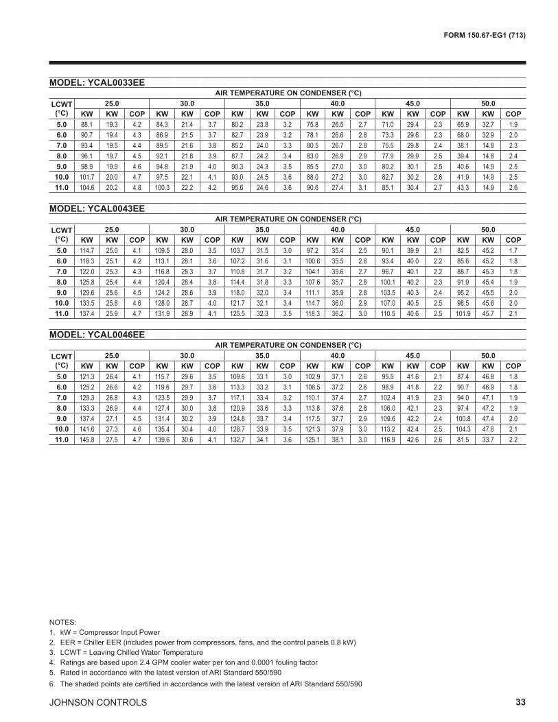
FORM 150.67-EG1 (713)
NOTES:1. kW = Compressor Input Power2. EER = Chiller EER (includes power from compressors, fans, and the control panels 0.8 kW)3. LCWT = Leaving Chilled Water Temperature4. Ratings are based upon 2.4 GPM cooler water per ton and 0.0001 fouling factor5. Rated in accordance with the latest version of ARI Standard 550/5906. The shaded points are certified in accordance with the latest version of ARI Standard 550/590
MODEL: YCAL0033EE AIR TEMPERATURE ON CONDENSER (°C)
LCWT(°C)
25.0 30.0 35.0 40.0 45.0 50.0KW KW COP KW KW COP KW KW COP KW KW COP KW KW COP KW KW COP
5.0 88.1 19.3 4.2 84.3 21.4 3.7 80.2 23.8 3.2 75.8 26.5 2.7 71.0 29.4 2.3 65.9 32.7 1.96.0 90.7 19.4 4.3 86.9 21.5 3.7 82.7 23.9 3.2 78.1 26.6 2.8 73.3 29.6 2.3 68.0 32.9 2.07.0 93.4 19.5 4.4 89.5 21.6 3.8 85.2 24.0 3.3 80.5 26.7 2.8 75.5 29.8 2.4 38.1 14.8 2.38.0 96.1 19.7 4.5 92.1 21.8 3.9 87.7 24.2 3.4 83.0 26.9 2.9 77.9 29.9 2.5 39.4 14.8 2.49.0 98.9 19.9 4.6 94.8 21.9 4.0 90.3 24.3 3.5 85.5 27.0 3.0 80.2 30.1 2.5 40.6 14.9 2.5
10.0 101.7 20.0 4.7 97.5 22.1 4.1 93.0 24.5 3.6 88.0 27.2 3.0 82.7 30.2 2.6 41.9 14.9 2.511.0 104.6 20.2 4.8 100.3 22.2 4.2 95.6 24.6 3.6 90.6 27.4 3.1 85.1 30.4 2.7 43.3 14.9 2.6
MODEL: YCAL0043EE AIR TEMPERATURE ON CONDENSER (°C)
LCWT(°C)
25.0 30.0 35.0 40.0 45.0 50.0KW KW COP KW KW COP KW KW COP KW KW COP KW KW COP KW KW COP
5.0 114.7 25.0 4.1 109.5 28.0 3.5 103.7 31.5 3.0 97.2 35.4 2.5 90.1 39.9 2.1 82.5 45.2 1.76.0 118.3 25.1 4.2 113.1 28.1 3.6 107.2 31.6 3.1 100.6 35.5 2.6 93.4 40.0 2.2 85.6 45.2 1.87.0 122.0 25.3 4.3 116.8 28.3 3.7 110.8 31.7 3.2 104.1 35.6 2.7 96.7 40.1 2.2 88.7 45.3 1.88.0 125.8 25.4 4.4 120.4 28.4 3.8 114.4 31.8 3.3 107.6 35.7 2.8 100.1 40.2 2.3 91.9 45.4 1.99.0 129.6 25.6 4.5 124.2 28.6 3.9 118.0 32.0 3.4 111.1 35.9 2.8 103.5 40.3 2.4 95.2 45.5 2.0
10.0 133.5 25.8 4.6 128.0 28.7 4.0 121.7 32.1 3.4 114.7 36.0 2.9 107.0 40.5 2.5 98.5 45.6 2.011.0 137.4 25.9 4.7 131.9 28.9 4.1 125.5 32.3 3.5 118.3 36.2 3.0 110.5 40.6 2.5 101.9 45.7 2.1
MODEL: YCAL0046EE AIR TEMPERATURE ON CONDENSER (°C)
LCWT(°C)
25.0 30.0 35.0 40.0 45.0 50.0KW KW COP KW KW COP KW KW COP KW KW COP KW KW COP KW KW COP
5.0 121.3 26.4 4.1 115.7 29.6 3.5 109.6 33.1 3.0 102.9 37.1 2.6 95.5 41.6 2.1 87.4 46.8 1.86.0 125.2 26.6 4.2 119.6 29.7 3.6 113.3 33.2 3.1 106.5 37.2 2.6 98.9 41.8 2.2 90.7 46.9 1.87.0 129.3 26.8 4.3 123.5 29.9 3.7 117.1 33.4 3.2 110.1 37.4 2.7 102.4 41.9 2.3 94.0 47.1 1.98.0 133.3 26.9 4.4 127.4 30.0 3.8 120.9 33.6 3.3 113.8 37.6 2.8 106.0 42.1 2.3 97.4 47.2 1.99.0 137.4 27.1 4.5 131.4 30.2 3.9 124.8 33.7 3.4 117.5 37.7 2.9 109.6 42.2 2.4 100.8 47.4 2.0
10.0 141.6 27.3 4.6 135.4 30.4 4.0 128.7 33.9 3.5 121.3 37.9 3.0 113.2 42.4 2.5 104.3 47.6 2.111.0 145.8 27.5 4.7 139.6 30.6 4.1 132.7 34.1 3.6 125.1 38.1 3.0 116.9 42.6 2.6 81.5 33.7 2.2
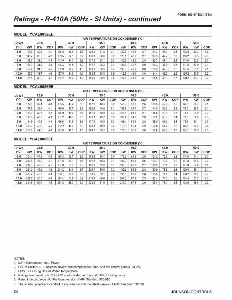
34
FORM 150.67-EG1 (713)
JOHNSON CONTROLS
NOTES:1. kW = Compressor Input Power2. EER = Chiller EER (includes power from compressors, fans, and the control panels 0.8 kW)3. LCWT = Leaving Chilled Water Temperature4. Ratings are based upon 2.4 GPM cooler water per ton and 0.0001 fouling factor5. Rated in accordance with the latest version of ARI Standard 550/5906. The shaded points are certified in accordance with the latest version of ARI Standard 550/590
Ratings - R-410A (50Hz - SI Units) - continued
MODEL: YCAL0052EE AIR TEMPERATURE ON CONDENSER (°C)
LCWT(°C)
25.0 30.0 35.0 40.0 45.0 50.0KW KW COP KW KW COP KW KW COP KW KW COP KW KW COP KW KW COP
5.0 140.8 30.6 4.1 135.2 33.9 3.6 129.0 37.8 3.1 122.2 42.1 2.7 114.7 47.0 2.3 106.5 52.3 1.96.0 145.2 30.8 4.2 139.5 34.1 3.7 133.2 38.0 3.2 126.1 42.3 2.7 118.5 47.2 2.3 110.2 52.5 2.07.0 149.7 31.0 4.3 143.9 34.3 3.8 137.4 38.1 3.3 130.2 42.5 2.8 122.3 47.4 2.4 113.8 52.8 2.08.0 154.3 31.2 4.4 148.3 34.5 3.9 141.7 38.3 3.4 134.3 42.7 2.9 126.3 47.6 2.5 117.6 53.0 2.19.0 158.9 31.5 4.5 152.9 34.7 4.0 146.0 38.5 3.4 138.5 42.9 3.0 130.3 47.8 2.5 121.4 53.2 2.1
10.0 163.7 31.7 4.6 157.5 34.9 4.1 150.5 38.8 3.5 142.8 43.1 3.0 134.4 48.0 2.6 125.2 53.5 2.211.0 168.5 32.0 4.7 162.2 35.2 4.2 155.0 39.0 3.6 147.1 43.3 3.1 138.5 48.3 2.7 129.2 53.7 2.2
MODEL: YCAL0056EE AIR TEMPERATURE ON CONDENSER (°C)
LCWT(°C)
25.0 30.0 35.0 40.0 45.0 50.0KW KW COP KW KW COP KW KW COP KW KW COP KW KW COP KW KW COP
5.0 172.6 39.1 4.0 165.5 43.4 3.5 157.6 48.3 3.0 148.9 53.8 2.6 139.5 59.9 2.2 69.6 29.7 2.16.0 177.9 39.4 4.1 170.6 43.7 3.6 162.5 48.6 3.1 153.6 54.1 2.7 144.0 60.2 2.3 72.0 29.8 2.17.0 183.3 39.7 4.2 175.9 44.0 3.7 167.6 48.9 3.2 158.5 54.5 2.7 148.6 60.6 2.3 74.5 29.9 2.28.0 188.8 40.0 4.3 181.2 44.3 3.8 172.7 49.2 3.3 163.4 54.8 2.8 153.2 60.9 2.4 77.0 30.0 2.39.0 194.5 40.3 4.4 186.6 44.6 3.9 177.9 49.5 3.3 168.4 55.1 2.9 158.0 61.3 2.4 79.6 30.1 2.3
10.0 200.2 40.6 4.5 192.2 44.9 3.9 183.3 49.9 3.4 173.5 55.4 2.9 162.8 61.7 2.5 82.3 30.2 2.411.0 206.0 41.0 4.6 197.8 45.3 4.0 188.7 50.2 3.5 178.6 55.8 3.0 167.8 62.0 2.6 85.0 30.3 2.5
MODEL: YCAL0066EE AIR TEMPERATURE ON CONDENSER (°C)
LCWT(°C)
25.0 30.0 35.0 40.0 45.0 50.0KW KW COP KW KW COP KW KW COP KW KW COP KW KW COP KW KW COP
5.0 204.4 47.8 4.0 195.3 52.7 3.5 185.6 58.4 3.0 175.2 64.8 2.6 164.2 72.2 2.2 113.8 54.4 2.06.0 210.8 48.2 4.1 201.5 53.1 3.5 191.5 58.8 3.1 181.0 65.3 2.6 169.7 72.7 2.2 117.8 54.6 2.07.0 217.3 48.6 4.1 207.8 53.5 3.6 197.6 59.2 3.1 186.8 65.7 2.7 175.3 73.1 2.3 121.8 54.9 2.18.0 224.0 49.1 4.2 214.2 54.0 3.7 203.7 59.6 3.2 192.6 66.2 2.8 180.9 73.6 2.3 126.0 55.1 2.19.0 230.7 49.5 4.3 220.7 54.4 3.8 210.0 60.1 3.3 198.6 66.6 2.8 186.6 74.1 2.4 130.2 55.4 2.2
10.0 237.6 50.0 4.4 227.4 54.9 3.9 216.4 60.6 3.4 204.8 67.1 2.9 192.4 74.6 2.5 134.5 55.7 2.311.0 244.6 50.4 4.5 234.2 55.3 4.0 222.9 61.0 3.4 211.0 67.6 3.0 198.4 75.1 2.5 138.9 56.0 2.3
JOHNSON CONTROLS 35
FORM 150.67-EG1 (713)
INTENTIONALLY LEFT BLANK
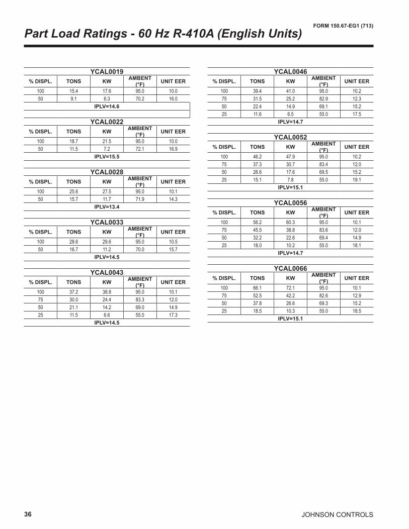
36
FORM 150.67-EG1 (713)
JOHNSON CONTROLS
Part Load Ratings - 60 Hz R-410A (English Units)
YCAL0019% DISPL. TONS KW AMBENT
(°F) UNIT EER
100 15.4 17.6 95.0 10.050 9.1 6.3 70.2 16.0
IPLV=14.6
YCAL0022% DISPL. TONS KW AMBIENT
(°F) UNIT EER
100 18.7 21.5 95.0 10.050 11.5 7.2 72.1 16.9
IPLV=15.5
YCAL0028% DISPL. TONS KW AMBIENT
(°F) UNIT EER
100 25.6 27.5 95.0 10.150 15.7 11.7 71.9 14.3
IPLV=13.4
YCAL0033% DISPL. TONS KW AMBIENT
(°F) UNIT EER
100 28.6 29.6 95.0 10.550 16.7 11.2 70.0 15.7
IPLV=14.5
YCAL0043% DISPL. TONS KW AMBIENT
(°F) UNIT EER
100 37.2 38.8 95.0 10.175 30.0 24.4 83.3 12.050 21.1 14.2 69.0 14.925 11.5 6.6 55.0 17.3
IPLV=14.5
YCAL0046% DISPL. TONS KW AMBIENT
(°F) UNIT EER
100 39.4 41.0 95.0 10.275 31.5 25.2 82.9 12.350 22.4 14.9 69.1 15.225 11.6 6.5 55.0 17.5
IPLV=14.7
YCAL0052% DISPL. TONS KW AMBIENT
(°F) UNIT EER
100 46.2 47.9 95.0 10.275 37.3 30.7 83.4 12.050 26.6 17.6 69.5 15.225 15.1 7.8 55.0 19.1
IPLV=15.1
YCAL0056% DISPL. TONS KW AMBIENT
(°F) UNIT EER
100 56.2 60.3 95.0 10.175 45.5 38.8 83.6 12.050 32.2 22.6 69.4 14.925 18.0 10.2 55.0 18.1
IPLV=14.7
YCAL0066% DISPL. TONS KW AMBIENT
(°F) UNIT EER
100 66.1 72.1 95.0 10.175 52.5 42.2 82.6 12.950 37.8 26.6 69.3 15.225 18.5 10.3 55.0 18.5
IPLV=15.1
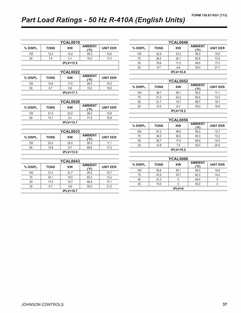
JOHNSON CONTROLS 37
FORM 150.67-EG1 (713)
Part Load Ratings - 50 Hz R-410A (English Units)
YCAL0019% DISPL. TONS KW AMBIENT
(°F) UNIT EER
100 13.0 14.2 95.0 10.650 7.6 5.1 70.2 17.0
IPLV=15.5
YCAL0022% DISPL. TONS KW AMBIENT
(°F) UNIT EER
100 15.6 17.6 95.0 10.350 9.7 5.6 72.0 18.8
IPLV=17.1
YCAL0028% DISPL. TONS KW AMBIENT
(°F) UNIT EER
100 21.4 22.0 95.0 10.850 13.1 9.1 71.6 15.8
IPLV=14.7
YCAL0033% DISPL. TONS KW AMBIENT
(°F) UNIT EER
100 24.0 24.0 95.0 11.150 13.8 8.7 69.6 17.3
IPLV=15.9
YCAL0043% DISPL. TONS KW AMBIENT
(°F) UNIT EER
100 31.2 31.7 95.0 10.775 25.1 19.5 83.3 13.250 17.6 10.7 68.8 17.125 9.7 4.6 55.0 21.5
IPLV=16.7
YCAL0046% DISPL. TONS KW AMBIENT
(°F) UNIT EER
100 32.9 33.3 95.0 10.875 26.2 20.1 82.8 13.550 18.6 11.5 68.9 17.025 9.7 4.6 55.0 21.7
IPLV=16.8
YCAL0052% DISPL. TONS KW AMBIENT
(°F) UNIT EER
100 38.7 38.1 95.0 11.175 31.0 24.0 83.0 13.350 21.7 13.7 68.7 16.725 12.0 6.3 55.0 19.9
IPLV=16.2
YCAL0056% DISPL. TONS KW AMBIENT
(°F) UNIT EER
100 47.2 48.8 95.0 10.775 38.0 30.6 83.3 13.250 26.7 17.4 68.9 16.525 14.8 7.9 55.0 20.0
IPLV=16.2
YCAL0066% DISPL. TONS KW AMBIENT
(°F) UNIT EER
100 55.6 59.1 95.0 10.675 43.9 33.7 82.3 14.050 31.2 0 69.0 025 15.0 0 55.0 0
IPLV=0
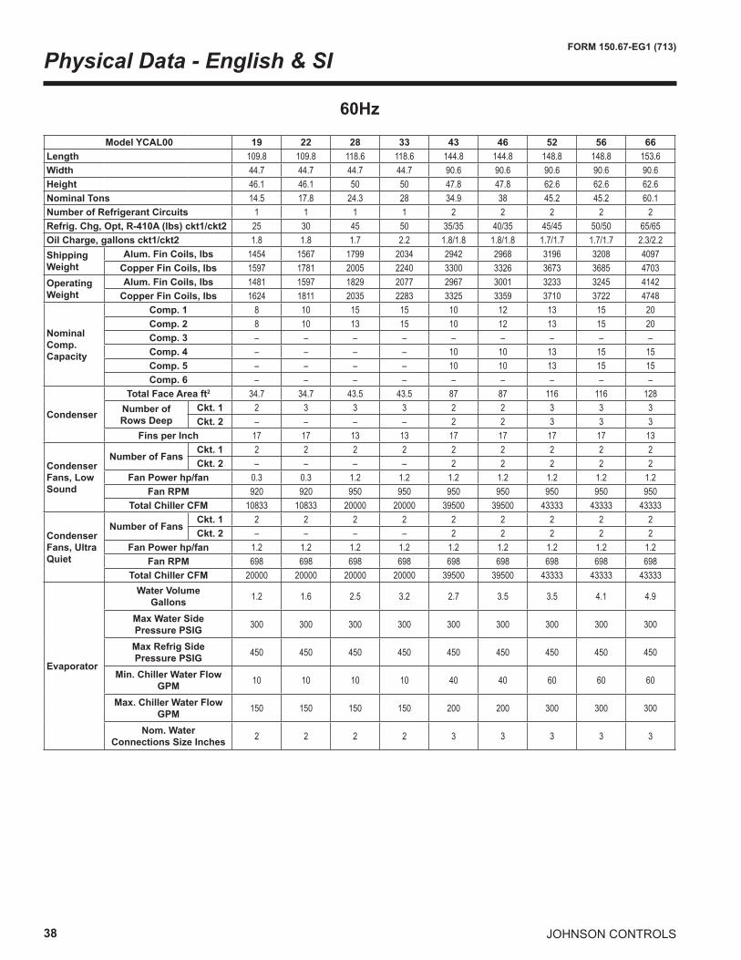
38
FORM 150.67-EG1 (713)
JOHNSON CONTROLS
Physical Data - English & SI
60Hz
Model YCAL00 19 22 28 33 43 46 52 56 66Length 109.8 109.8 118.6 118.6 144.8 144.8 148.8 148.8 153.6Width 44.7 44.7 44.7 44.7 90.6 90.6 90.6 90.6 90.6Height 46.1 46.1 50 50 47.8 47.8 62.6 62.6 62.6Nominal Tons 14.5 17.8 24.3 28 34.9 38 45.2 45.2 60.1Number of Refrigerant Circuits 1 1 1 1 2 2 2 2 2Refrig. Chg, Opt, R-410A (lbs) ckt1/ckt2 25 30 45 50 35/35 40/35 45/45 50/50 65/65Oil Charge, gallons ckt1/ckt2 1.8 1.8 1.7 2.2 1.8/1.8 1.8/1.8 1.7/1.7 1.7/1.7 2.3/2.2Shipping Weight
Alum. Fin Coils, lbs 1454 1567 1799 2034 2942 2968 3196 3208 4097Copper Fin Coils, lbs 1597 1781 2005 2240 3300 3326 3673 3685 4703
Operating Weight
Alum. Fin Coils, lbs 1481 1597 1829 2077 2967 3001 3233 3245 4142Copper Fin Coils, lbs 1624 1811 2035 2283 3325 3359 3710 3722 4748
Nominal Comp. Capacity
Comp. 1 8 10 15 15 10 12 13 15 20Comp. 2 8 10 13 15 10 12 13 15 20Comp. 3 – – – – – – – – –Comp. 4 – – – – 10 10 13 15 15Comp. 5 – – – – 10 10 13 15 15Comp. 6 – – – – – – – – –
Condenser
Total Face Area ft2 34.7 34.7 43.5 43.5 87 87 116 116 128Number of Rows Deep
Ckt. 1 2 3 3 3 2 2 3 3 3Ckt. 2 – – – – 2 2 3 3 3
Fins per Inch 17 17 13 13 17 17 17 17 13
Condenser Fans, Low Sound
Number of FansCkt. 1 2 2 2 2 2 2 2 2 2Ckt. 2 – – – – 2 2 2 2 2
Fan Power hp/fan 0.3 0.3 1.2 1.2 1.2 1.2 1.2 1.2 1.2Fan RPM 920 920 950 950 950 950 950 950 950
Total Chiller CFM 10833 10833 20000 20000 39500 39500 43333 43333 43333
Condenser Fans, Ultra Quiet
Number of FansCkt. 1 2 2 2 2 2 2 2 2 2Ckt. 2 – – – – 2 2 2 2 2
Fan Power hp/fan 1.2 1.2 1.2 1.2 1.2 1.2 1.2 1.2 1.2Fan RPM 698 698 698 698 698 698 698 698 698
Total Chiller CFM 20000 20000 20000 20000 39500 39500 43333 43333 43333
Evaporator
Water VolumeGallons 1.2 1.6 2.5 3.2 2.7 3.5 3.5 4.1 4.9
Max Water SidePressure PSIG 300 300 300 300 300 300 300 300 300
Max Refrig SidePressure PSIG 450 450 450 450 450 450 450 450 450
Min. Chiller Water FlowGPM 10 10 10 10 40 40 60 60 60
Max. Chiller Water FlowGPM 150 150 150 150 200 200 300 300 300
Nom. WaterConnections Size Inches 2 2 2 2 3 3 3 3 3
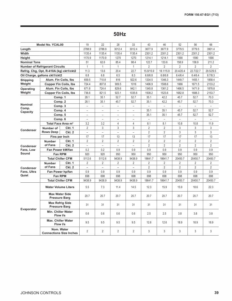
JOHNSON CONTROLS 39
FORM 150.67-EG1 (713)
50Hz
Model No. YCAL00 19 22 28 33 43 46 52 56 66Length 2788.9 2788.9 3012.4 3012.4 3677.9 3677.9 3779.5 3779.5 3901.4Width 1135.4 1135.4 1135.4 1135.4 2301.2 2301.2 2301.2 2301.2 2301.2Height 1170.9 1170.9 1270 1270 1214.1 1214.1 1590 1590 1590Nominal Tons 51 62.6 85.4 98.4 122.7 133.6 158.9 158.9 211.2Number of Refrigerant Circuits 1 1 1 1 2 2 2 2 2Refrig. Chg, Opt, R-410A (kg) ckt1/ckt2 11.3 13.6 20.4 22.7 15.9/15.9 18.1/15.9 20.4/20.4 22.7/22.7 29.5/29.5Oil Charge, gallons ckt1/ckt2 6.8 6.8 6.5 8.3 6.8/6.8 6.8/6.8 6.4/6.4 6.4/6.4 8.7/8.3Shipping Weight
Alum. Fin Coils, lbs 659.5 710.8 816 922.6 1334.5 1346.3 1449.7 1455.1 1858.4Copper Fin Coils, lbs 724.4 807.8 909.5 1016 1496.9 1508.6 1666 1671.5 2133.2
Operating Weight
Alum. Fin Coils, lbs 671.8 724.4 829.6 942.1 1345.8 1361.2 1466.5 1471.9 1878.8Copper Fin Coils, lbs 736.6 821.5 923.1 1035.6 1508.2 1523.6 1682.8 1688.3 2153.7
Nominal Comp. Capacity
Comp. 1 28.1 35.1 52.7 52.7 35.1 42.2 45.7 52.7 70.3Comp. 2 28.1 35.1 45.7 52.7 35.1 42.2 45.7 52.7 70.3Comp. 3 – – – – – – – – –Comp. 4 – – – – 35.1 35.1 45.7 52.7 52.7Comp. 5 – – – – 35.1 35.1 45.7 52.7 52.7Comp. 6 – – – – – – – – –
Condenser
Total Face Area m2 3.2 3.2 4 4 8.1 8.1 10.8 10.8 11.9Number of Rows Deep
Ckt. 1 2 3 3 3 2 2 3 3 3Ckt. 2 – – – – 2 2 3 3 3
Fins per Inch 17 17 13 13 17 17 17 17 13
Condenser Fans, Low Sound
Number of Fans
Ckt. 1 2 2 2 2 2 2 2 2 2Ckt. 2 – – – – 2 2 2 2 2
Fan Power kW/fan 0.2 0.2 0.9 0.9 0.9 0.9 0.9 0.9 0.9Fan RPM 920 920 950 950 950 950 950 950 950
Total Chiller CFM 5112.6 5112.6 9438.9 9438.9 18641.7 18641.7 20450.7 20450.7 20450.7
Condenser Fans, Ultra Quiet
Number of Fans
Ckt. 1 2 2 2 2 2 2 2 2 2Ckt. 2 – – – – 2 2 2 2 2
Fan Power hp/fan 0.9 0.9 0.9 0.9 0.9 0.9 0.9 0.9 0.9Fan RPM 698 698 698 698 698 698 698 698 698
Total Chiller CFM 9438.9 9438.9 9438.9 9438.9 18641.7 18641.7 20450.7 20450.7 20450.7
Evaporator
Water Volume Liters 5.5 7.3 11.4 14.5 12.3 15.9 15.9 18.6 22.3
Max Water Side Pressure Barg 20.7 20.7 20.7 20.7 20.7 20.7 20.7 20.7 20.7
Max Refrig Side Pressure Barg 31 31 31 31 31 31 31 31 31
Min. Chiller WaterFlow l/s 0.6 0.6 0.6 0.6 2.5 2.5 3.8 3.8 3.8
Max. Chiller WaterFlow l/s 9.5 9.5 9.5 9.5 12.6 12.6 18.9 18.9 18.9
Nom. WaterConnections Size Inches 2 2 2 2 3 3 3 3 3
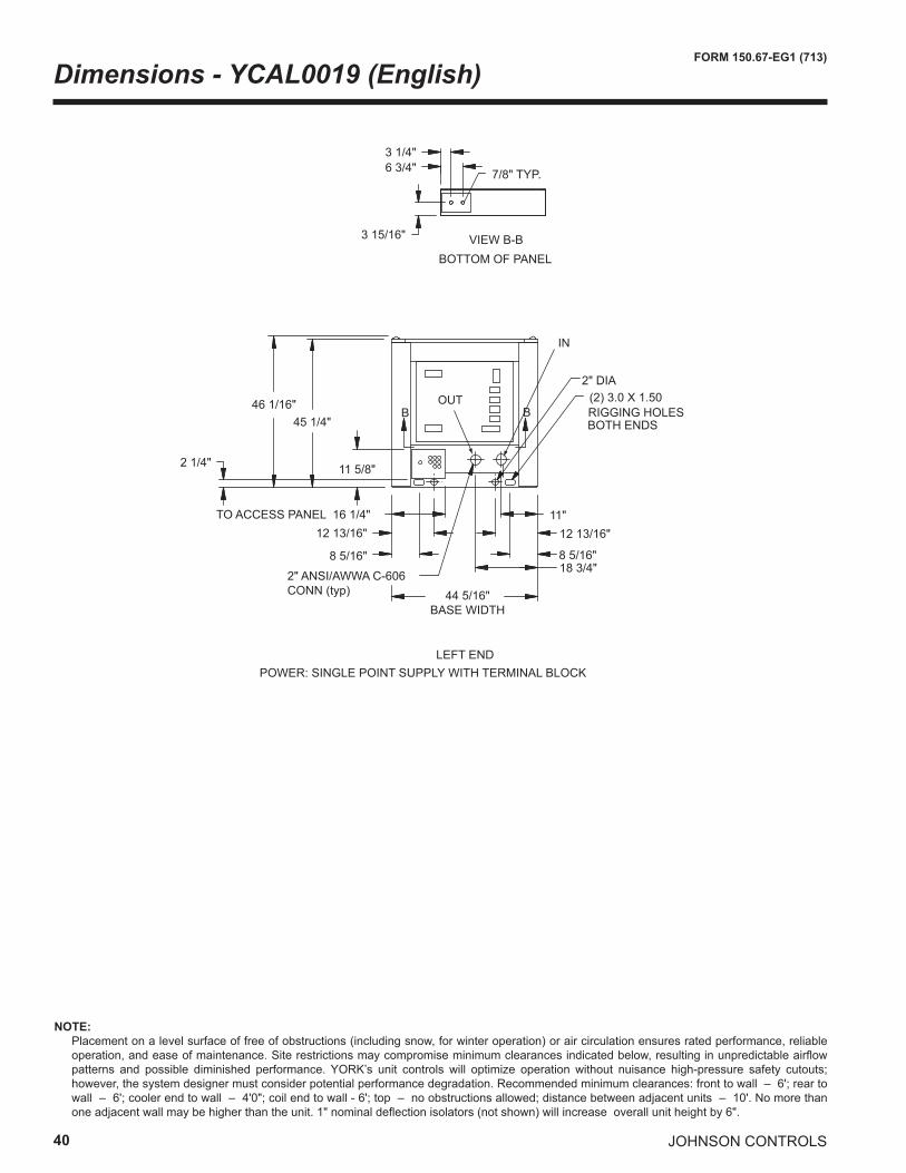
40
FORM 150.67-EG1 (713)
JOHNSON CONTROLS
Dimensions - YCAL0019 (English)
NOTE: Placement on a level surface of free of obstructions (including snow, for winter operation) or air circulation ensures rated performance, reliable
operation, and ease of maintenance. Site restrictions may compromise minimum clearances indicated below, resulting in unpredictable airflow patterns and possible diminished performance. YORK’s unit controls will optimize operation without nuisance high-pressure safety cutouts; however, the system designer must consider potential performance degradation. Recommended minimum clearances: front to wall – 6'; rear to wall – 6'; cooler end to wall – 4'0"; coil end to wall - 6'; top – no obstructions allowed; distance between adjacent units – 10'. No more than one adjacent wall may be higher than the unit. 1" nominal deflection isolators (not shown) will increase overall unit height by 6".
LEFT END
6 3/4"3 1/4"
3 15/16"
BOTTOM OF PANEL
7/8" TYP.
VIEW B-B
POWER: SINGLE POINT SUPPLY WITH TERMINAL BLOCK
46 1/16"45 1/4"
11 5/8"
2" DIA(2) 3.0 X 1.50RIGGING HOLES BOTH ENDS
44 5/16" BASE WIDTH
18 3/4"
11"TO ACCESS PANEL 16 1/4"
8 5/16"
12 13/16"
8 5/16"
12 13/16"
B B
2 1/4"
2" ANSI/AWWA C-606 CONN (typ)
OUT
IN
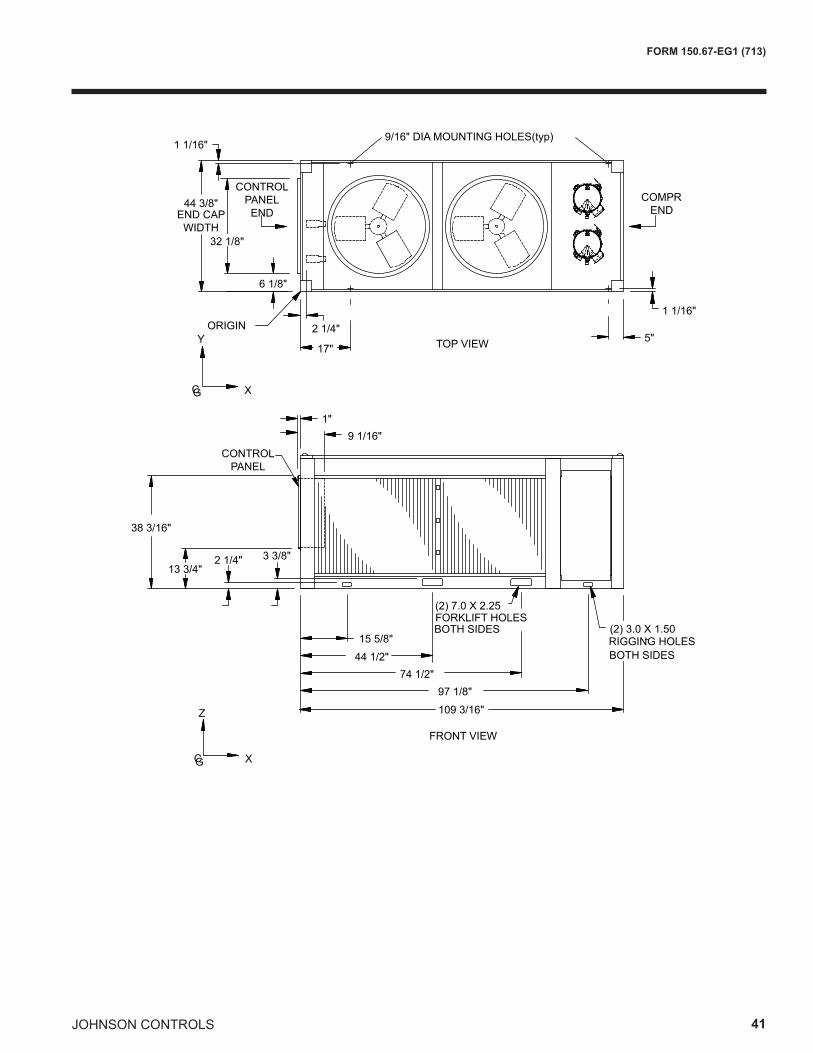
JOHNSON CONTROLS 41
FORM 150.67-EG1 (713)
TOP VIEW
9/16" DIA MOUNTING HOLES(typ)
COMPR END
1 1/16"
5"17"
2 1/4"ORIGINY
CG X
44 3/8"
32 1/8"
6 1/8"
1 1/16"
CONTROL PANEL ENDEND CAP
WIDTH
FRONT VIEW
109 3/16"
RIGGING HOLES(2) 3.0 X 1.50
BOTH SIDES15 5/8"
44 1/2"74 1/2"
97 1/8"
(2) 7.0 X 2.25FORKLIFT HOLES BOTH SIDES
CG X
Z
2 1/4" 3 3/8"13 3/4"
38 3/16"
9 1/16"1"
CONTROL PANEL
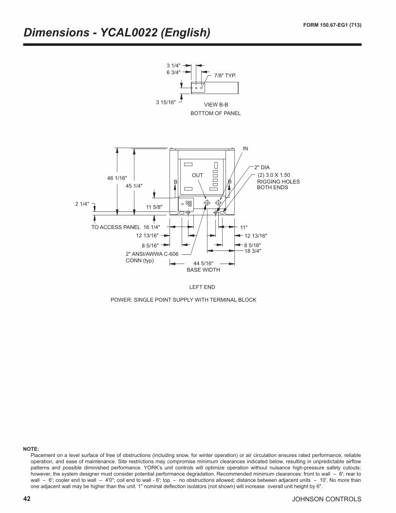
42
FORM 150.67-EG1 (713)
JOHNSON CONTROLS
Dimensions - YCAL0022 (English)
LEFT END
6 3/4"3 1/4"
3 15/16"
BOTTOM OF PANEL
7/8" TYP.
VIEW B-B
POWER: SINGLE POINT SUPPLY WITH TERMINAL BLOCK
46 1/16"45 1/4"
11 5/8"
2" DIA(2) 3.0 X 1.50RIGGING HOLES BOTH ENDS
44 5/16" BASE WIDTH
18 3/4"
11"TO ACCESS PANEL 16 1/4"
8 5/16"
12 13/16"
8 5/16"
12 13/16"
B B
2 1/4"
2" ANSI/AWWA C-606 CONN (typ)
IN
OUT
NOTE: Placement on a level surface of free of obstructions (including snow, for winter operation) or air circulation ensures rated performance, reliable
operation, and ease of maintenance. Site restrictions may compromise minimum clearances indicated below, resulting in unpredictable airflow patterns and possible diminished performance. YORK’s unit controls will optimize operation without nuisance high-pressure safety cutouts; however, the system designer must consider potential performance degradation. Recommended minimum clearances: front to wall – 6'; rear to wall – 6'; cooler end to wall – 4'0"; coil end to wall - 6'; top – no obstructions allowed; distance between adjacent units – 10'. No more than one adjacent wall may be higher than the unit. 1" nominal deflection isolators (not shown) will increase overall unit height by 6".
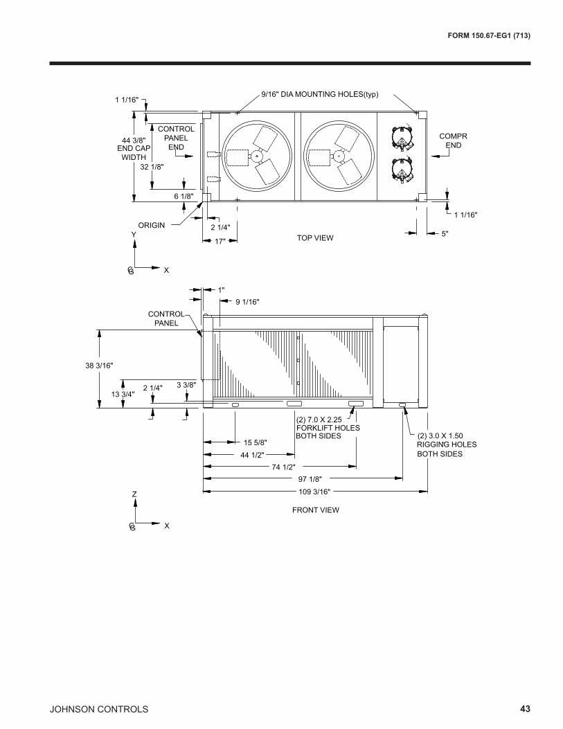
JOHNSON CONTROLS 43
FORM 150.67-EG1 (713)
TOP VIEW
9/16" DIA MOUNTING HOLES(typ)
COMPR END
1 1/16"
5"17"
2 1/4"ORIGINY
CG X
44 3/8"
32 1/8"
6 1/8"
1 1/16"
CONTROL PANEL ENDEND CAP
WIDTH
FRONT VIEW
109 3/16"
RIGGING HOLES(2) 3.0 X 1.50
BOTH SIDES15 5/8"
44 1/2"74 1/2"
97 1/8"
(2) 7.0 X 2.25FORKLIFT HOLES BOTH SIDES
CG X
Z
2 1/4" 3 3/8"13 3/4"
38 3/16"
9 1/16"1"
CONTROL PANEL
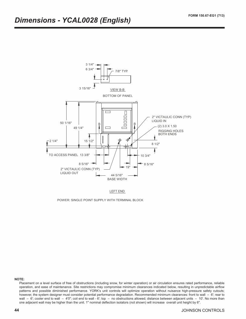
44
FORM 150.67-EG1 (713)
JOHNSON CONTROLS
Dimensions - YCAL0028 (English)
NOTE: Placement on a level surface of free of obstructions (including snow, for winter operation) or air circulation ensures rated performance, reliable
operation, and ease of maintenance. Site restrictions may compromise minimum clearances indicated below, resulting in unpredictable airflow patterns and possible diminished performance. YORK’s unit controls will optimize operation without nuisance high-pressure safety cutouts; however, the system designer must consider potential performance degradation. Recommended minimum clearances: front to wall – 6'; rear to wall – 6'; cooler end to wall – 4'0"; coil end to wall - 6'; top – no obstructions allowed; distance between adjacent units – 10'. No more than one adjacent wall may be higher than the unit. 1" nominal deflection isolators (not shown) will increase overall unit height by 6".
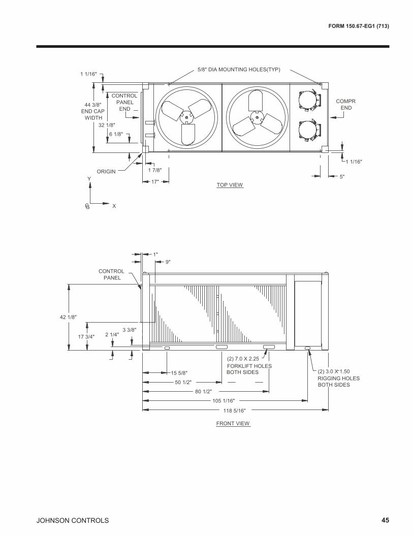
JOHNSON CONTROLS 45
FORM 150.67-EG1 (713)
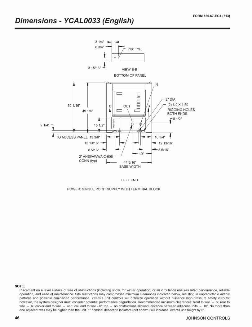
46
FORM 150.67-EG1 (713)
JOHNSON CONTROLS
Dimensions - YCAL0033 (English)
44 5/16" BASE WIDTH
50 1/16"49 1/4"
6 3/4"3 1/4"
3 15/16"
LEFT END
BOTTOM OF PANEL
7/8" TYP.
VIEW B-B
POWER: SINGLE POINT SUPPLY WITH TERMINAL BLOCK
19"
10 3/4"
8 1/2"
2" ANSI/AWWA C-606 CONN (typ)
B B
15 1/2"
TO ACCESS PANEL 13 3/8"
2 1/4"
8 5/16"
12 13/16"
8 5/16"
12 13/16"
2" DIA(2) 3.0 X 1.50RIGGING HOLES BOTH ENDS
IN
OUT
NOTE: Placement on a level surface of free of obstructions (including snow, for winter operation) or air circulation ensures rated performance, reliable
operation, and ease of maintenance. Site restrictions may compromise minimum clearances indicated below, resulting in unpredictable airflow patterns and possible diminished performance. YORK’s unit controls will optimize operation without nuisance high-pressure safety cutouts; however, the system designer must consider potential performance degradation. Recommended minimum clearances: front to wall – 6'; rear to wall – 6'; cooler end to wall – 4'0"; coil end to wall - 6'; top – no obstructions allowed; distance between adjacent units – 10'. No more than one adjacent wall may be higher than the unit. 1" nominal deflection isolators (not shown) will increase overall unit height by 6".
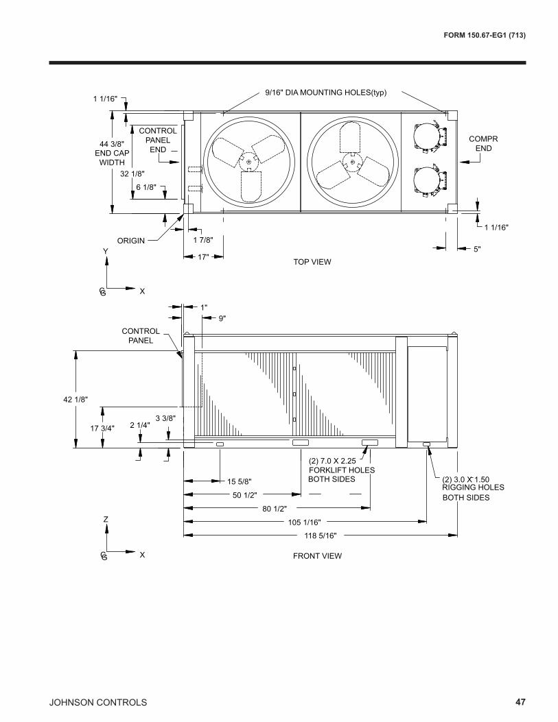
JOHNSON CONTROLS 47
FORM 150.67-EG1 (713)
2 1/4"3 3/8"
17 3/4"
42 1/8"
9"
44 3/8"
32 1/8"
15 5/8"
50 1/2"
80 1/2"
105 1/16"
6 1/8"
1"
1 1/16"
1 1/16"
5"17"
FRONT VIEW
TOP VIEW
9/16" DIA MOUNTING HOLES(typ)
CONTROL PANEL
CONTROL PANEL END
COMPR END
ORIGINY
CG X
CG X
Z
END CAPWIDTH
118 5/16"
RIGGING HOLES
(2) 7.0 X 2.25FORKLIFT HOLES BOTH SIDES (2) 3.0 X 1.50
BOTH SIDES
1 7/8"
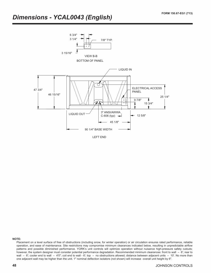
48
FORM 150.67-EG1 (713)
JOHNSON CONTROLS
Dimensions - YCAL0043 (English)
VIEW B-B3 15/16"
3 1/4"6 3/4"
BOTTOM OF PANEL
7/8" TYP.
47 3/4"
46 15/16"
45 1/8"
12 5/8"3" ANSI/AWWAC-606 (typ)
90 1/4" BASE WIDTH
LEFT END
LIQUID OUT
25 1/4"
15 3/4"9 7/8"
ELECTRICAL ACCESS PANEL
LIQUID IN
NOTE: Placement on a level surface of free of obstructions (including snow, for winter operation) or air circulation ensures rated performance, reliable
operation, and ease of maintenance. Site restrictions may compromise minimum clearances indicated below, resulting in unpredictable airflow patterns and possible diminished performance. YORK’s unit controls will optimize operation without nuisance high-pressure safety cutouts; however, the system designer must consider potential performance degradation. Recommended minimum clearances: front to wall – 6'; rear to wall – 6'; cooler end to wall – 4'0"; coil end to wall - 6'; top – no obstructions allowed; distance between adjacent units – 10'. No more than one adjacent wall may be higher than the unit. 1" nominal deflection isolators (not shown) will increase overall unit height by 6".
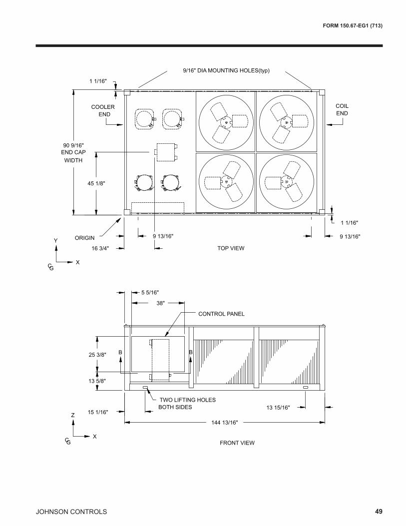
JOHNSON CONTROLS 49
FORM 150.67-EG1 (713)
90 9/16"
45 1/8"
Y
CGX
1 1/16"
ORIGIN
END CAPWIDTH
16 3/4" TOP VIEW
9 13/16"
1 1/16"
9 13/16"
9/16" DIA MOUNTING HOLES(typ)
144 13/16"
15 1/16"13 15/16"
TWO LIFTING HOLES BOTH SIDES
FRONT VIEWCGX
Z
38"
5 5/16"
25 3/8"
13 5/8"
B B
COILEND
COOLEREND
CONTROL PANEL
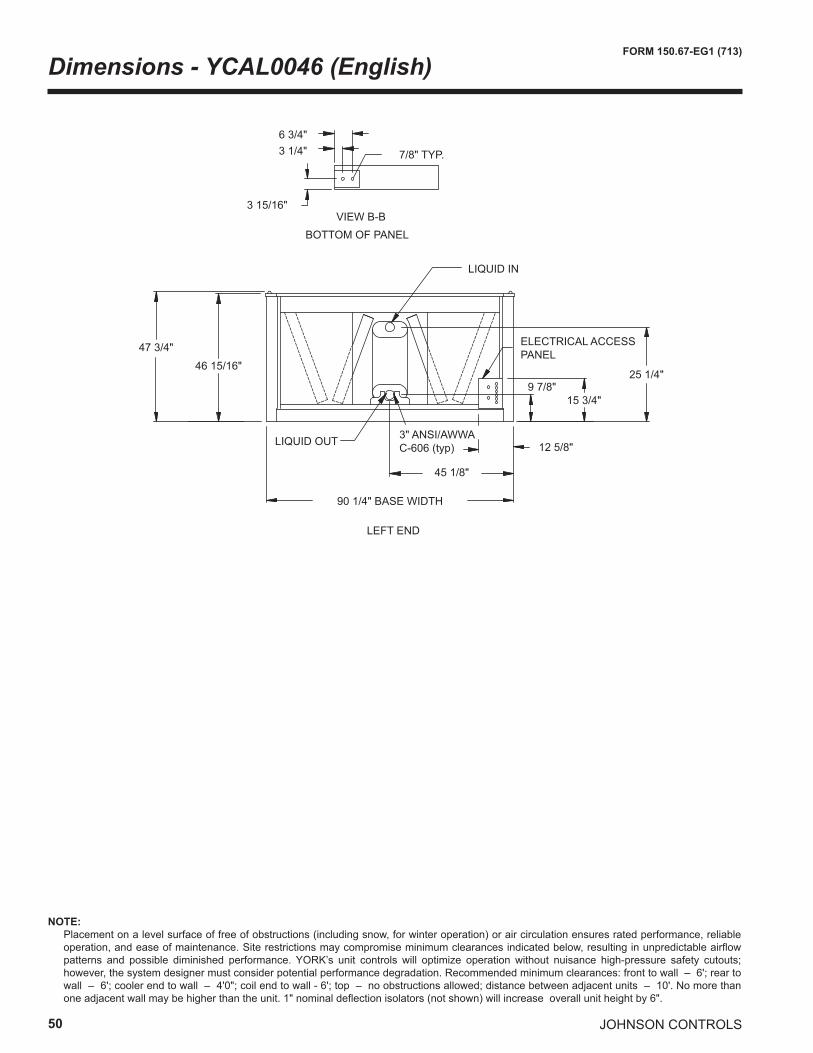
50
FORM 150.67-EG1 (713)
JOHNSON CONTROLS
Dimensions - YCAL0046 (English)
VIEW B-B3 15/16"
3 1/4"6 3/4"
BOTTOM OF PANEL
7/8" TYP.
47 3/4"
46 15/16"
45 1/8"
12 5/8"3" ANSI/AWWAC-606 (typ)
90 1/4" BASE WIDTH
LEFT END
LIQUID OUT
25 1/4"
15 3/4"9 7/8"
ELECTRICAL ACCESS PANEL
LIQUID IN
NOTE: Placement on a level surface of free of obstructions (including snow, for winter operation) or air circulation ensures rated performance, reliable
operation, and ease of maintenance. Site restrictions may compromise minimum clearances indicated below, resulting in unpredictable airflow patterns and possible diminished performance. YORK’s unit controls will optimize operation without nuisance high-pressure safety cutouts; however, the system designer must consider potential performance degradation. Recommended minimum clearances: front to wall – 6'; rear to wall – 6'; cooler end to wall – 4'0"; coil end to wall - 6'; top – no obstructions allowed; distance between adjacent units – 10'. No more than one adjacent wall may be higher than the unit. 1" nominal deflection isolators (not shown) will increase overall unit height by 6".
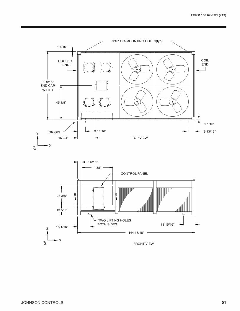
JOHNSON CONTROLS 51
FORM 150.67-EG1 (713)
90 9/16"
45 1/8"
Y
CGX
1 1/16"
ORIGIN
END CAPWIDTH
16 3/4" TOP VIEW
9 13/16"
1 1/16"
9 13/16"
9/16" DIA MOUNTING HOLES(typ)
144 13/16"
15 1/16"13 15/16"
TWO LIFTING HOLES BOTH SIDES
FRONT VIEWCGX
Z
38"
5 5/16"
25 3/8"
13 5/8"
B B
COILEND
COOLEREND
CONTROL PANEL
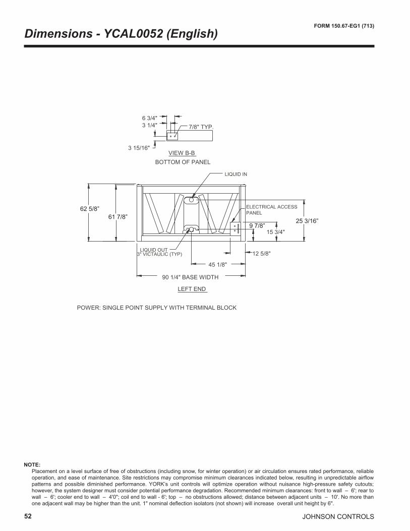
52
FORM 150.67-EG1 (713)
JOHNSON CONTROLS
Dimensions - YCAL0052 (English)
9 7/8”25 3/16”
62 5/8”61 7/8”
NOTE: Placement on a level surface of free of obstructions (including snow, for winter operation) or air circulation ensures rated performance, reliable
operation, and ease of maintenance. Site restrictions may compromise minimum clearances indicated below, resulting in unpredictable airflow patterns and possible diminished performance. YORK’s unit controls will optimize operation without nuisance high-pressure safety cutouts; however, the system designer must consider potential performance degradation. Recommended minimum clearances: front to wall – 6'; rear to wall – 6'; cooler end to wall – 4'0"; coil end to wall - 6'; top – no obstructions allowed; distance between adjacent units – 10'. No more than one adjacent wall may be higher than the unit. 1" nominal deflection isolators (not shown) will increase overall unit height by 6".
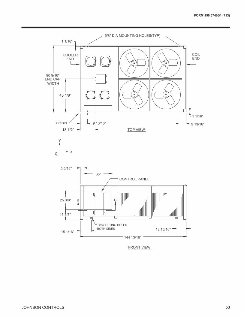
JOHNSON CONTROLS 53
FORM 150.67-EG1 (713)
45 1/8”
18 1/2”
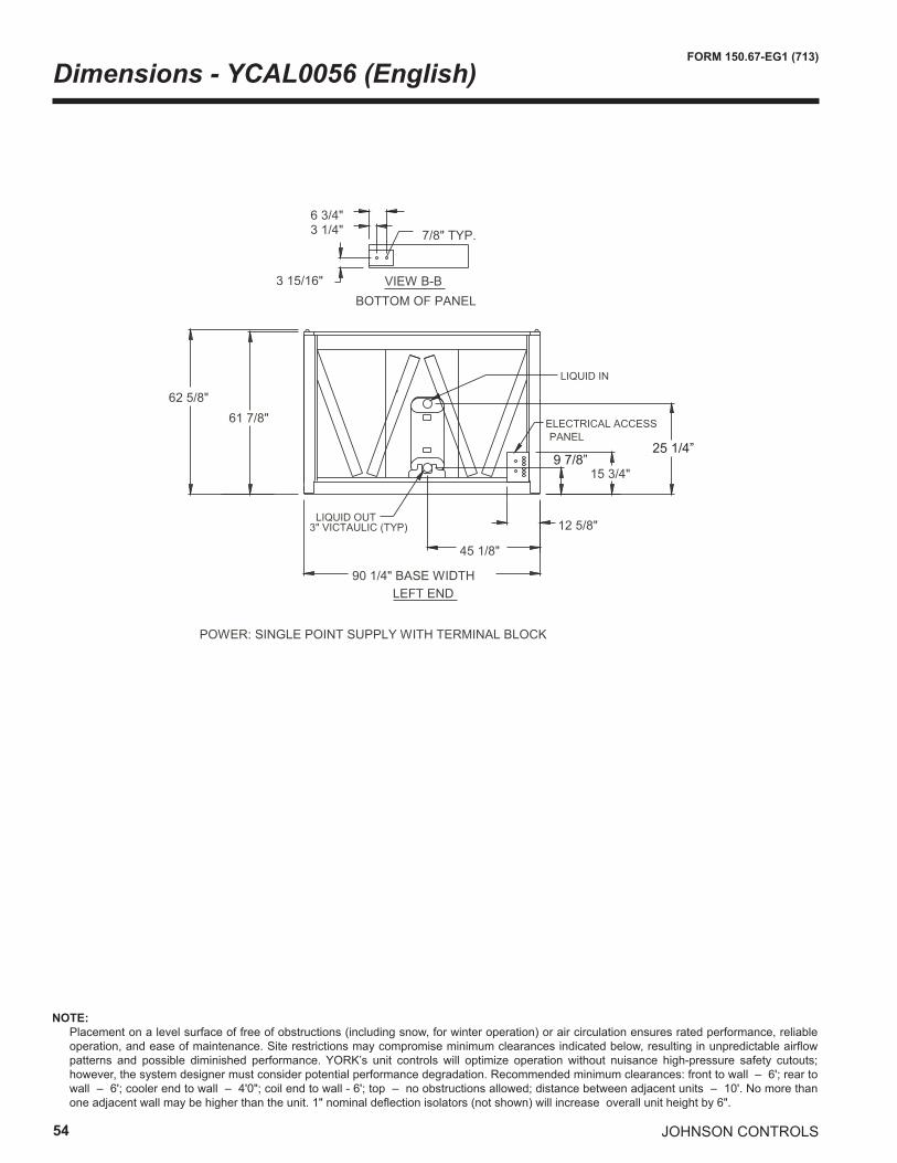
54
FORM 150.67-EG1 (713)
JOHNSON CONTROLS
Dimensions - YCAL0056 (English)
9 7/8”25 1/4”
NOTE: Placement on a level surface of free of obstructions (including snow, for winter operation) or air circulation ensures rated performance, reliable
operation, and ease of maintenance. Site restrictions may compromise minimum clearances indicated below, resulting in unpredictable airflow patterns and possible diminished performance. YORK’s unit controls will optimize operation without nuisance high-pressure safety cutouts; however, the system designer must consider potential performance degradation. Recommended minimum clearances: front to wall – 6'; rear to wall – 6'; cooler end to wall – 4'0"; coil end to wall - 6'; top – no obstructions allowed; distance between adjacent units – 10'. No more than one adjacent wall may be higher than the unit. 1" nominal deflection isolators (not shown) will increase overall unit height by 6".
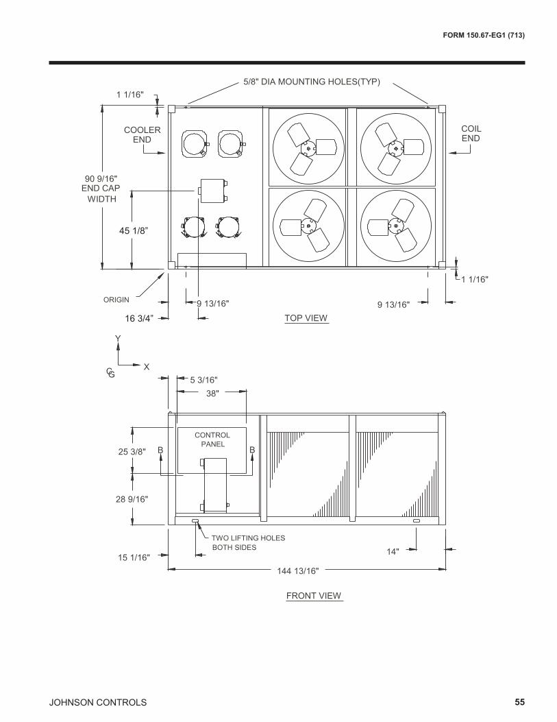
JOHNSON CONTROLS 55
FORM 150.67-EG1 (713)
45 1/8”
16 3/4”
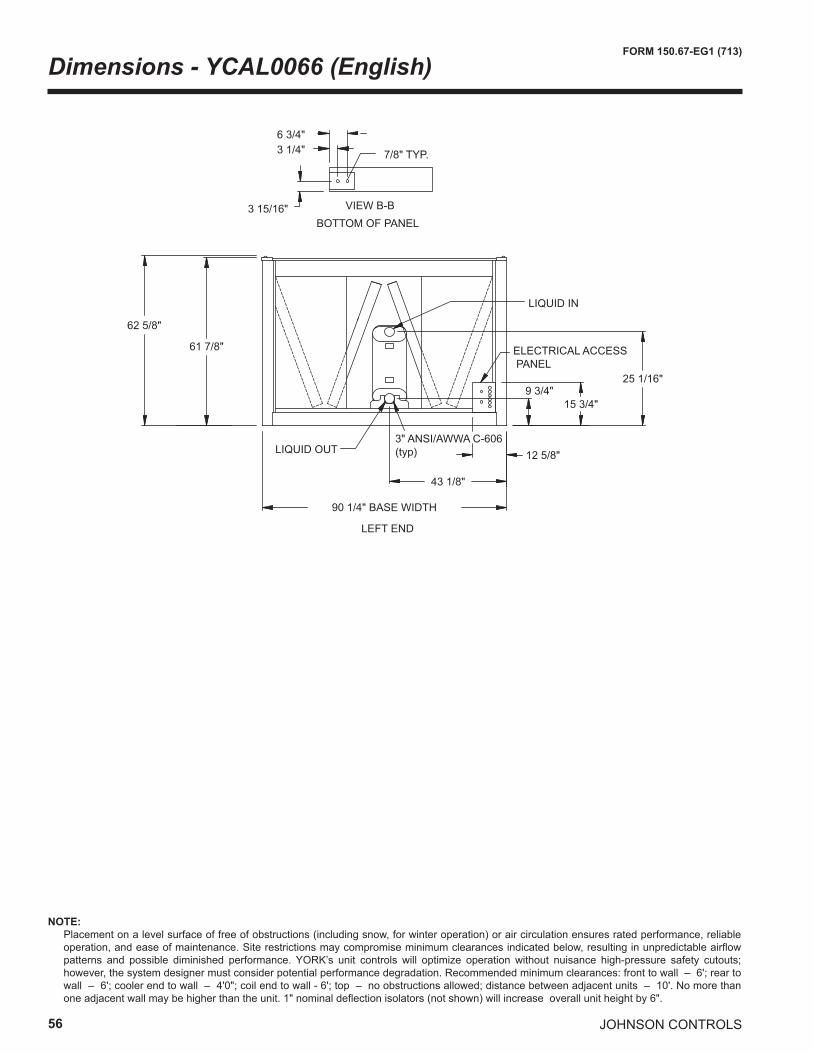
56
FORM 150.67-EG1 (713)
JOHNSON CONTROLS
Dimensions - YCAL0066 (English)
62 5/8"
61 7/8"
25 1/16"
15 3/4"9 3/4"
43 1/8"
12 5/8"3" ANSI/AWWA C-606 (typ)
ELECTRICAL ACCESS PANEL
90 1/4" BASE WIDTH
LEFT END
LIQUID OUT
LIQUID IN
VIEW B-B
7/8" TYP.
3 15/16"
3 1/4"6 3/4"
BOTTOM OF PANEL
NOTE: Placement on a level surface of free of obstructions (including snow, for winter operation) or air circulation ensures rated performance, reliable
operation, and ease of maintenance. Site restrictions may compromise minimum clearances indicated below, resulting in unpredictable airflow patterns and possible diminished performance. YORK’s unit controls will optimize operation without nuisance high-pressure safety cutouts; however, the system designer must consider potential performance degradation. Recommended minimum clearances: front to wall – 6'; rear to wall – 6'; cooler end to wall – 4'0"; coil end to wall - 6'; top – no obstructions allowed; distance between adjacent units – 10'. No more than one adjacent wall may be higher than the unit. 1" nominal deflection isolators (not shown) will increase overall unit height by 6".
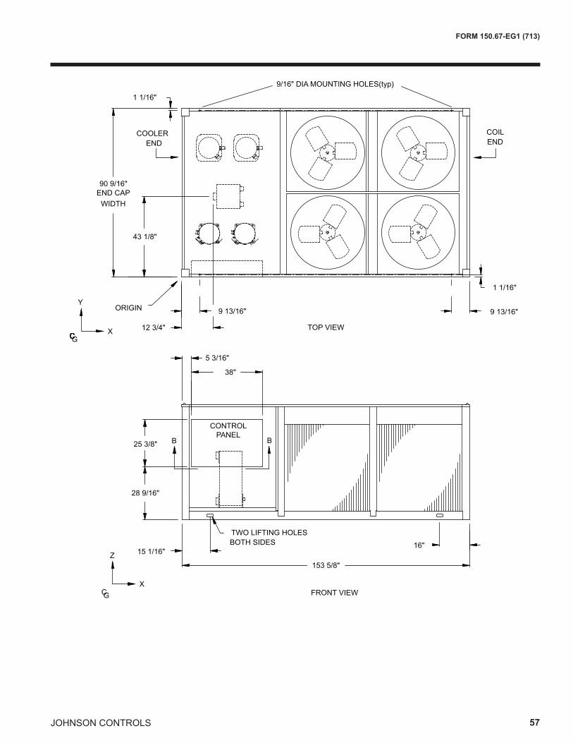
JOHNSON CONTROLS 57
FORM 150.67-EG1 (713)
90 9/16"
43 1/8"
12 3/4"
38"
5 3/16"
153 5/8"
15 1/16"16"
25 3/8"
28 9/16"
CONTROL PANEL
TWO LIFTING HOLES BOTH SIDES
Y
TOP VIEWCG
X
FRONT VIEWCGX
Z
1 1/16"
1 1/16"
ORIGIN 9 13/16" 9 13/16"
B B
9/16" DIA MOUNTING HOLES(typ)
END CAPWIDTH
COILEND
COOLEREND
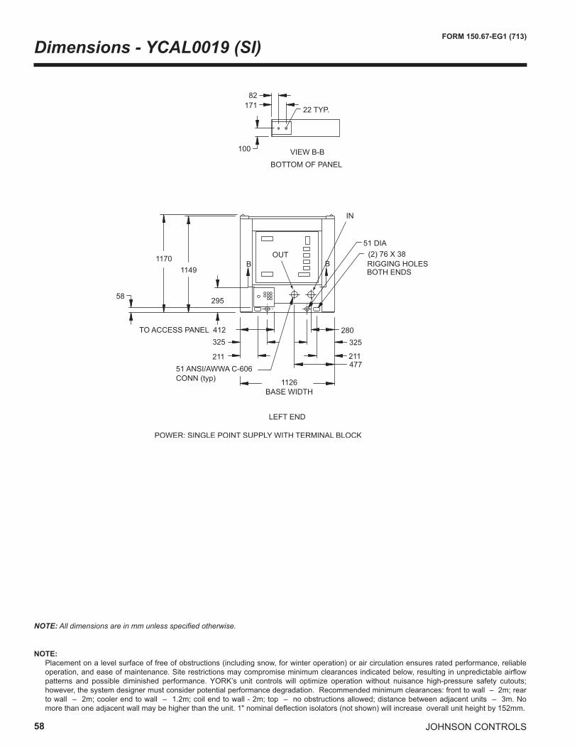
58
FORM 150.67-EG1 (713)
JOHNSON CONTROLS
Dimensions - YCAL0019 (SI)
LEFT END
17182
100
BOTTOM OF PANEL
22 TYP.
VIEW B-B
POWER: SINGLE POINT SUPPLY WITH TERMINAL BLOCK
11701149
295
51 DIA(2) 76 X 38RIGGING HOLES BOTH ENDS
1126 BASE WIDTH
477
280TO ACCESS PANEL 412
211
325
211
325
B B
58
51 ANSI/AWWA C-606 CONN (typ)
IN
OUT
NOTE: All dimensions are in mm unless specified otherwise.
NOTE: Placement on a level surface of free of obstructions (including snow, for winter operation) or air circulation ensures rated performance, reliable
operation, and ease of maintenance. Site restrictions may compromise minimum clearances indicated below, resulting in unpredictable airflow patterns and possible diminished performance. YORK’s unit controls will optimize operation without nuisance high-pressure safety cutouts; however, the system designer must consider potential performance degradation. Recommended minimum clearances: front to wall – 2m; rear to wall – 2m; cooler end to wall – 1.2m; coil end to wall - 2m; top – no obstructions allowed; distance between adjacent units – 3m. No more than one adjacent wall may be higher than the unit. 1" nominal deflection isolators (not shown) will increase overall unit height by 152mm.
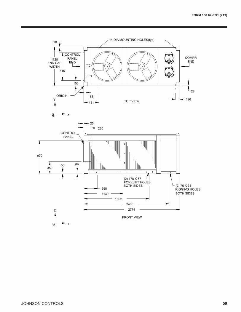
JOHNSON CONTROLS 59
FORM 150.67-EG1 (713)
TOP VIEW
14 DIA MOUNTING HOLES(typ)
COMPR END
28
126431
58ORIGINY
CG X
1128
815
156
28
CONTROL PANEL ENDEND CAP
WIDTH
FRONT VIEW
2774
RIGGING HOLES(2) 76 X 38
BOTH SIDES398
11301892
2466
(2) 178 X 57FORKLIFT HOLES BOTH SIDES
CG X
Z
58 86350
970
23025
CONTROL PANEL
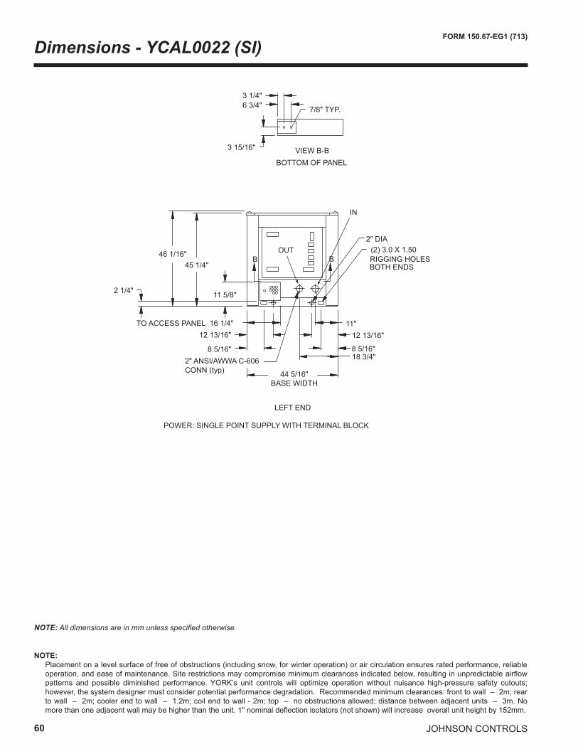
60
FORM 150.67-EG1 (713)
JOHNSON CONTROLS
Dimensions - YCAL0022 (SI)
LEFT END
6 3/4"3 1/4"
3 15/16"
BOTTOM OF PANEL
7/8" TYP.
VIEW B-B
POWER: SINGLE POINT SUPPLY WITH TERMINAL BLOCK
46 1/16"45 1/4"
11 5/8"
2" DIA(2) 3.0 X 1.50RIGGING HOLES BOTH ENDS
44 5/16" BASE WIDTH
18 3/4"
11"TO ACCESS PANEL 16 1/4"
8 5/16"
12 13/16"
8 5/16"
12 13/16"
B B
2 1/4"
2" ANSI/AWWA C-606 CONN (typ)
IN
OUT
NOTE: All dimensions are in mm unless specified otherwise.
NOTE: Placement on a level surface of free of obstructions (including snow, for winter operation) or air circulation ensures rated performance, reliable
operation, and ease of maintenance. Site restrictions may compromise minimum clearances indicated below, resulting in unpredictable airflow patterns and possible diminished performance. YORK’s unit controls will optimize operation without nuisance high-pressure safety cutouts; however, the system designer must consider potential performance degradation. Recommended minimum clearances: front to wall – 2m; rear to wall – 2m; cooler end to wall – 1.2m; coil end to wall - 2m; top – no obstructions allowed; distance between adjacent units – 3m. No more than one adjacent wall may be higher than the unit. 1" nominal deflection isolators (not shown) will increase overall unit height by 152mm.
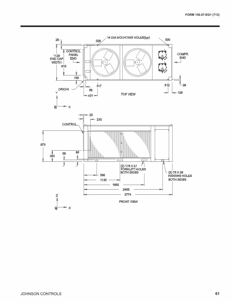
JOHNSON CONTROLS 61
FORM 150.67-EG1 (713)
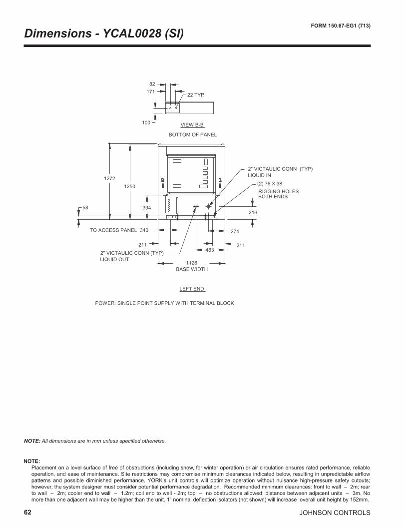
62
FORM 150.67-EG1 (713)
JOHNSON CONTROLS
Dimensions - YCAL0028 (SI)
NOTE: All dimensions are in mm unless specified otherwise.
���������������
��������
�����
���
�� �����
������� �����
������
��������
�����������������������������������������
���
���
���
��������������������� ���������
���
�������������������
��
��� ���
���������������������� ���������
�� �������������������������������
NOTE: Placement on a level surface of free of obstructions (including snow, for winter operation) or air circulation ensures rated performance, reliable
operation, and ease of maintenance. Site restrictions may compromise minimum clearances indicated below, resulting in unpredictable airflow patterns and possible diminished performance. YORK’s unit controls will optimize operation without nuisance high-pressure safety cutouts; however, the system designer must consider potential performance degradation. Recommended minimum clearances: front to wall – 2m; rear to wall – 2m; cooler end to wall – 1.2m; coil end to wall - 2m; top – no obstructions allowed; distance between adjacent units – 3m. No more than one adjacent wall may be higher than the unit. 1" nominal deflection isolators (not shown) will increase overall unit height by 152mm.
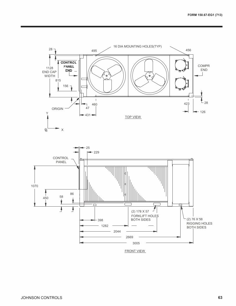
JOHNSON CONTROLS 63
FORM 150.67-EG1 (713)
5886
450
1070
229
1128
815
398
1282
2044
2669
156
25
28
28
126431
CONTROL PANEL
COMPR END
ORIGINY
CG X
END CAPWIDTH
3005
RIGGING HOLES
(2) 178 X 57FORKLIFT HOLES BOTH SIDES (2) 76 X 38
BOTH SIDES
47
FRONT VIEW
TOP VIEW
495 456
423 460
16 DIA MOUNTING HOLES(TYP)
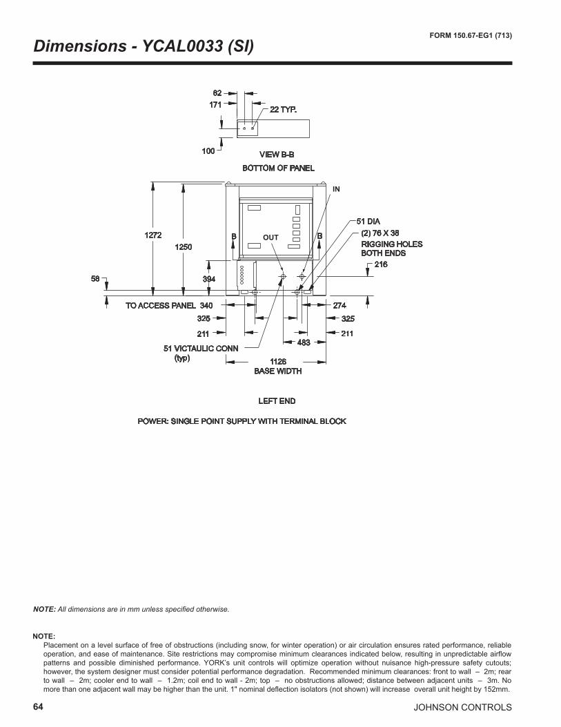
64
FORM 150.67-EG1 (713)
JOHNSON CONTROLS
Dimensions - YCAL0033 (SI)
1126 BASE WIDTH
12721250
17182
100
LEFT END
BOTTOM OF PANEL
22 TYP.
VIEW B-B
POWER: SINGLE POINT SUPPLY WITH TERMINAL BLOCK
483
274
216
51 VICTAULIC CONN (typ)
B B
394
TO ACCESS PANEL 340
58
211
325
211
325
51 DIA(2) 76 X 38RIGGING HOLES BOTH ENDS
IN
OUT
NOTE: All dimensions are in mm unless specified otherwise.
NOTE: Placement on a level surface of free of obstructions (including snow, for winter operation) or air circulation ensures rated performance, reliable
operation, and ease of maintenance. Site restrictions may compromise minimum clearances indicated below, resulting in unpredictable airflow patterns and possible diminished performance. YORK’s unit controls will optimize operation without nuisance high-pressure safety cutouts; however, the system designer must consider potential performance degradation. Recommended minimum clearances: front to wall – 2m; rear to wall – 2m; cooler end to wall – 1.2m; coil end to wall - 2m; top – no obstructions allowed; distance between adjacent units – 3m. No more than one adjacent wall may be higher than the unit. 1" nominal deflection isolators (not shown) will increase overall unit height by 152mm.
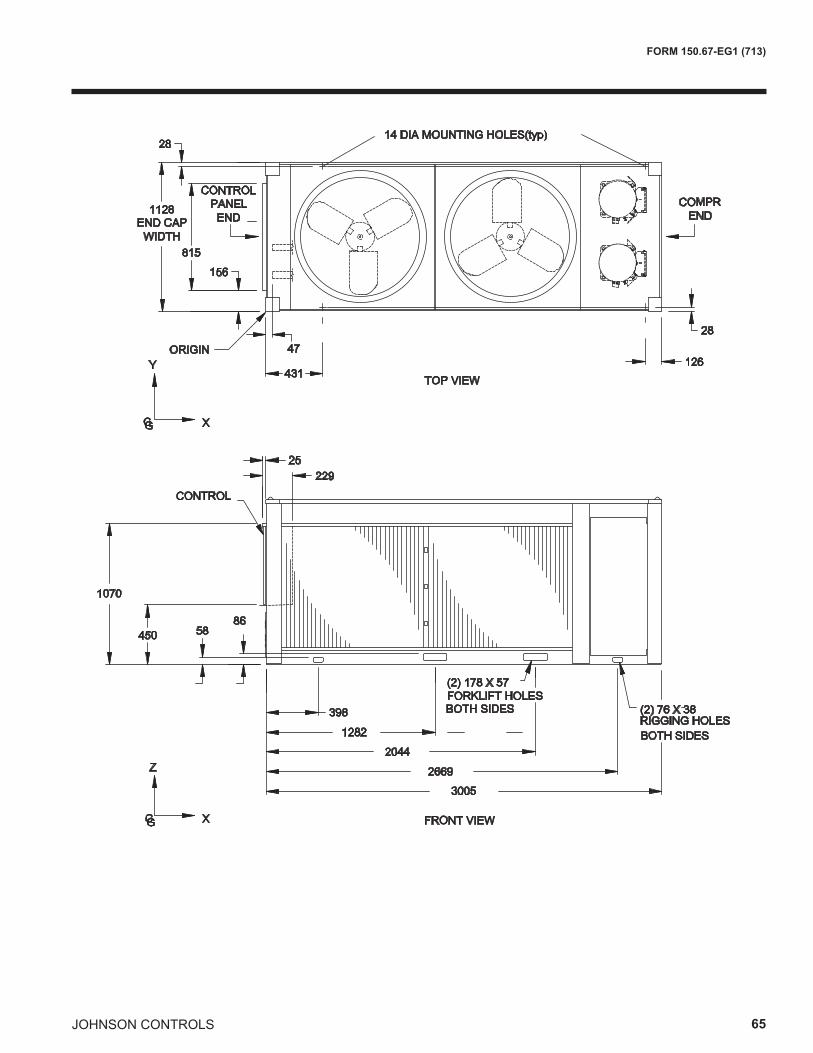
JOHNSON CONTROLS 65
FORM 150.67-EG1 (713)
5886
450
1070
229
1128
815
3981282
20442669
156
25
28
28
126431
FRONT VIEW
TOP VIEW
14 DIA MOUNTING HOLES(typ)
CONTROL
CONTROL PANEL END
COMPR END
ORIGINY
CG X
CG X
Z
END CAPWIDTH
3005
RIGGING HOLES
(2) 178 X 57FORKLIFT HOLES BOTH SIDES (2) 76 X 38
BOTH SIDES
47
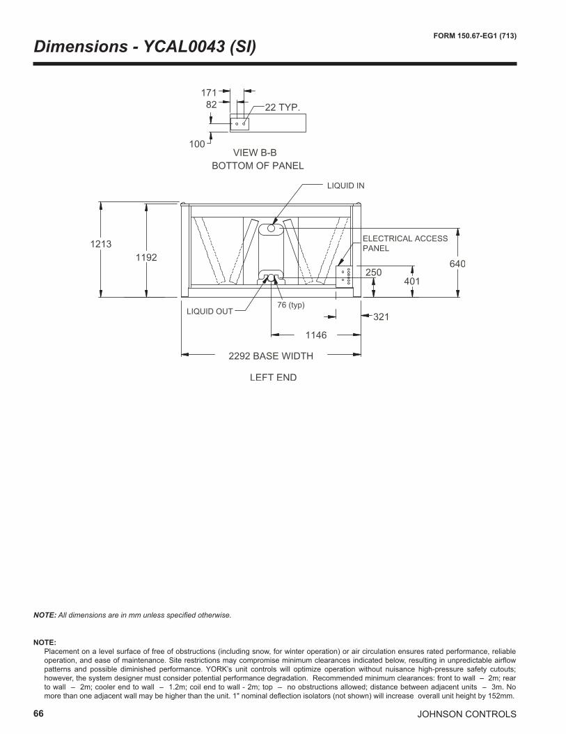
66
FORM 150.67-EG1 (713)
JOHNSON CONTROLS
Dimensions - YCAL0043 (SI)
NOTE: All dimensions are in mm unless specified otherwise.
�����������
�����
������������ ��
������
�������
����
����������
���������������
���� � �
����������
���
������
��� �� ���� ������ ��
��������
NOTE: Placement on a level surface of free of obstructions (including snow, for winter operation) or air circulation ensures rated performance, reliable
operation, and ease of maintenance. Site restrictions may compromise minimum clearances indicated below, resulting in unpredictable airflow patterns and possible diminished performance. YORK’s unit controls will optimize operation without nuisance high-pressure safety cutouts; however, the system designer must consider potential performance degradation. Recommended minimum clearances: front to wall – 2m; rear to wall – 2m; cooler end to wall – 1.2m; coil end to wall - 2m; top – no obstructions allowed; distance between adjacent units – 3m. No more than one adjacent wall may be higher than the unit. 1" nominal deflection isolators (not shown) will increase overall unit height by 152mm.
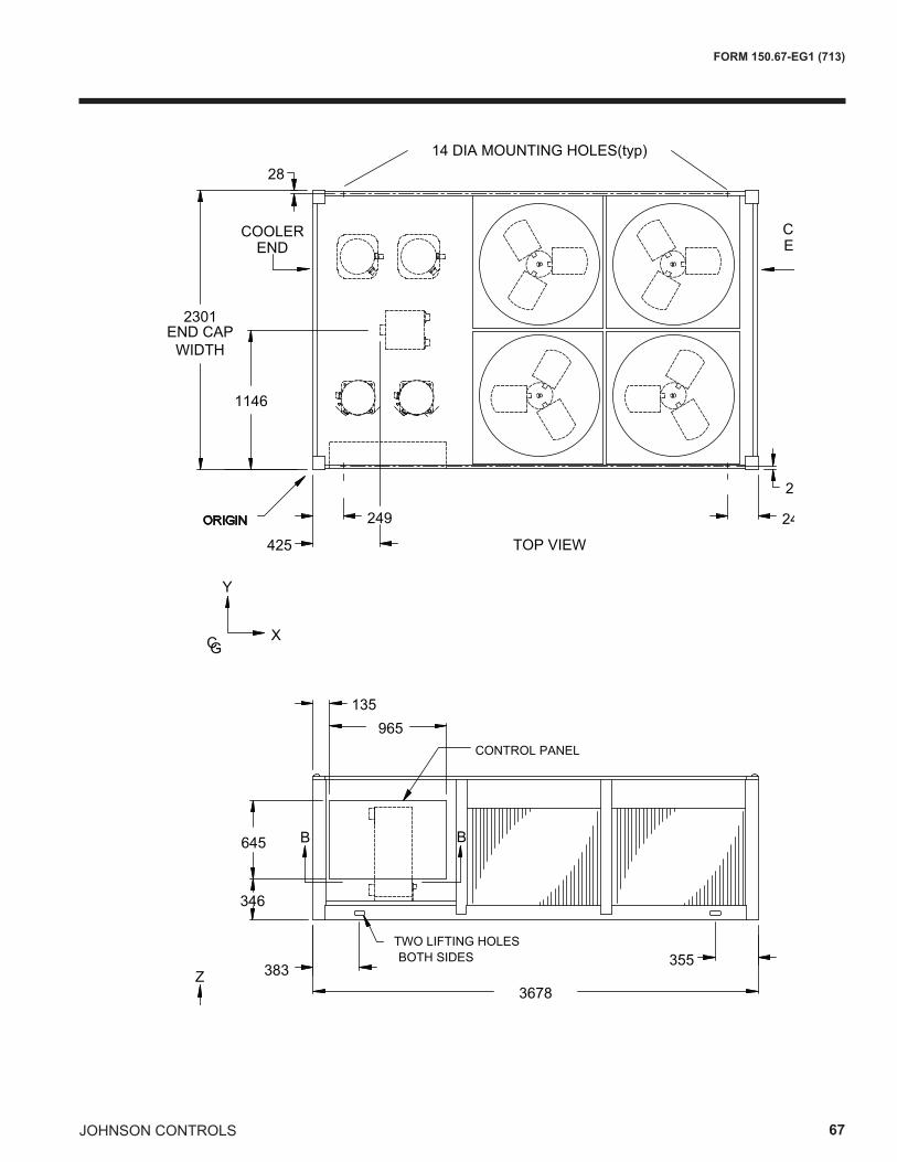
JOHNSON CONTROLS 67
FORM 150.67-EG1 (713)
2301
1146
Y
CGX
28
ORIGIN
END CAPWIDTH
425 TOP VIEW
249
28
249
14 DIA MOUNTING HOLES(typ)
3678383
355TWO LIFTING HOLES BOTH SIDES
FRONT VIEWCGX
Z
965135
645
346
B B
COILEND
COOLEREND
CONTROL PANEL
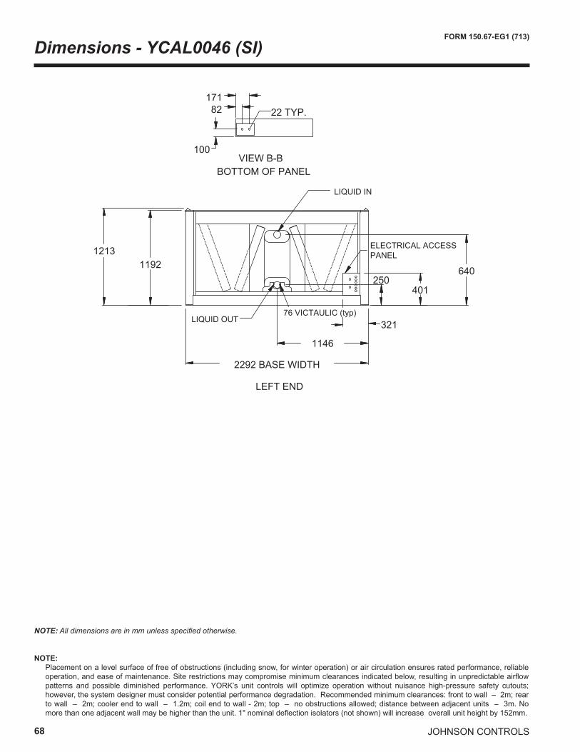
68
FORM 150.67-EG1 (713)
JOHNSON CONTROLS
Dimensions - YCAL0046 (SI)
VIEW B-B100
82171
BOTTOM OF PANEL
22 TYP.
12131192
1146
32176 VICTAULIC (typ)
2292 BASE WIDTH
LEFT END
LIQUID OUT
640
401250
ELECTRICAL ACCESS PANEL
LIQUID IN
NOTE: All dimensions are in mm unless specified otherwise.
NOTE: Placement on a level surface of free of obstructions (including snow, for winter operation) or air circulation ensures rated performance, reliable
operation, and ease of maintenance. Site restrictions may compromise minimum clearances indicated below, resulting in unpredictable airflow patterns and possible diminished performance. YORK’s unit controls will optimize operation without nuisance high-pressure safety cutouts; however, the system designer must consider potential performance degradation. Recommended minimum clearances: front to wall – 2m; rear to wall – 2m; cooler end to wall – 1.2m; coil end to wall - 2m; top – no obstructions allowed; distance between adjacent units – 3m. No more than one adjacent wall may be higher than the unit. 1" nominal deflection isolators (not shown) will increase overall unit height by 152mm.
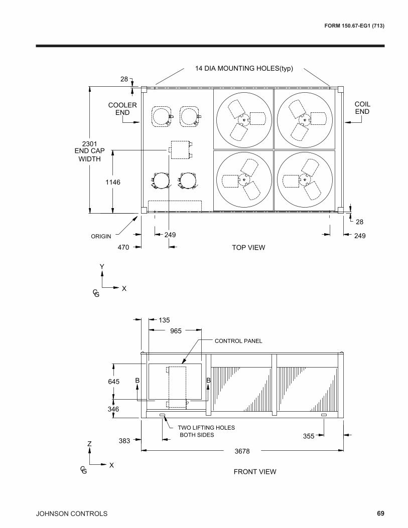
JOHNSON CONTROLS 69
FORM 150.67-EG1 (713)
2301
1146
Y
CGX
28
ORIGIN
END CAPWIDTH
470 TOP VIEW
249
28
249
14 DIA MOUNTING HOLES(typ)
3678383
355TWO LIFTING HOLES BOTH SIDES
FRONT VIEWCGX
Z
965135
645
346
B B
COILEND
COOLEREND
CONTROL PANEL
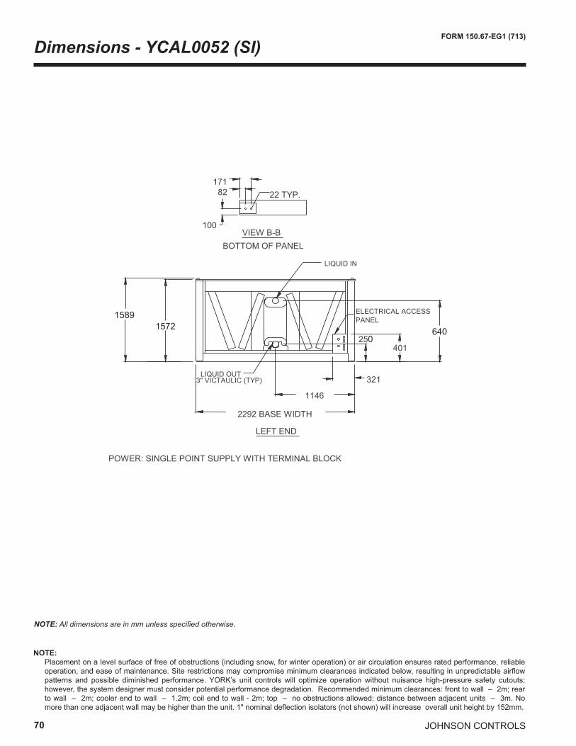
70
FORM 150.67-EG1 (713)
JOHNSON CONTROLS
Dimensions - YCAL0052 (SI)
NOTE: All dimensions are in mm unless specified otherwise.
0640
15891572
NOTE: Placement on a level surface of free of obstructions (including snow, for winter operation) or air circulation ensures rated performance, reliable
operation, and ease of maintenance. Site restrictions may compromise minimum clearances indicated below, resulting in unpredictable airflow patterns and possible diminished performance. YORK’s unit controls will optimize operation without nuisance high-pressure safety cutouts; however, the system designer must consider potential performance degradation. Recommended minimum clearances: front to wall – 2m; rear to wall – 2m; cooler end to wall – 1.2m; coil end to wall - 2m; top – no obstructions allowed; distance between adjacent units – 3m. No more than one adjacent wall may be higher than the unit. 1" nominal deflection isolators (not shown) will increase overall unit height by 152mm.
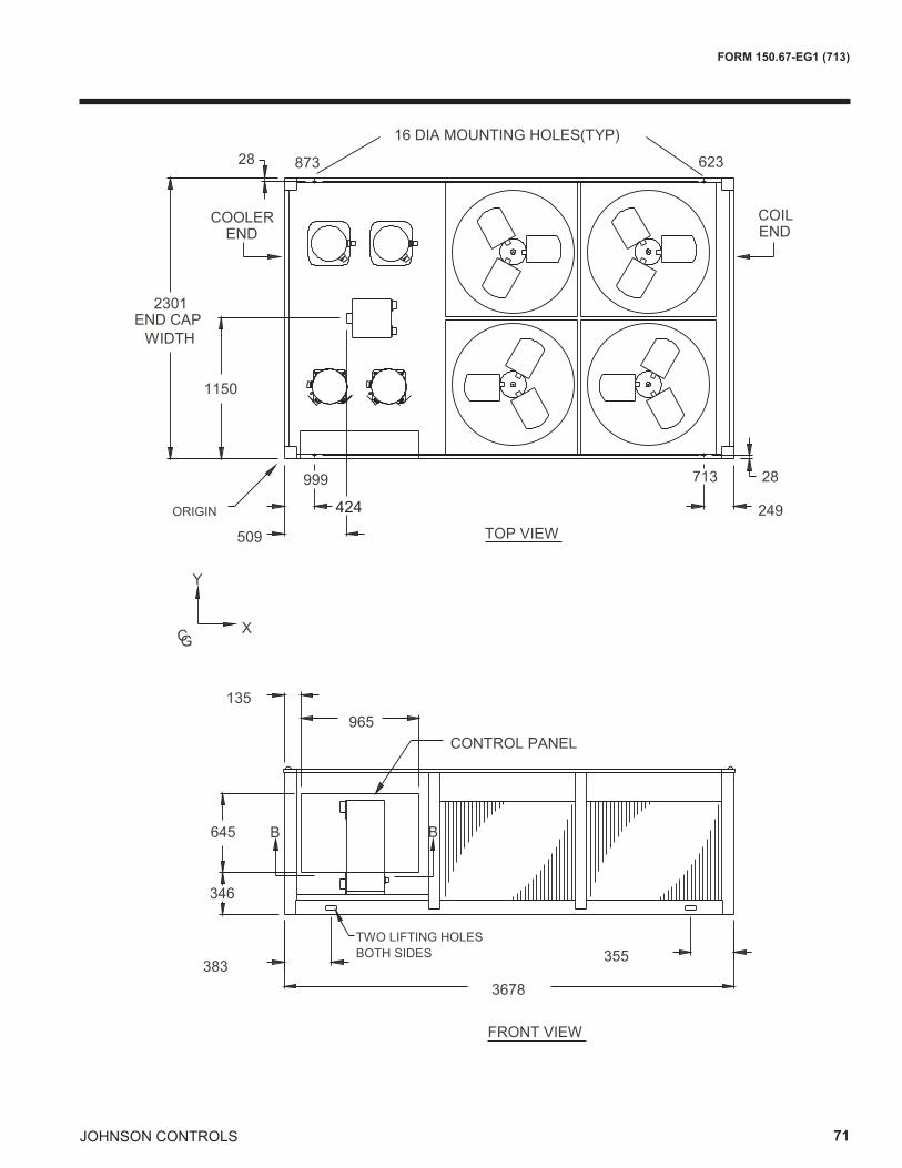
JOHNSON CONTROLS 71
FORM 150.67-EG1 (713)
424
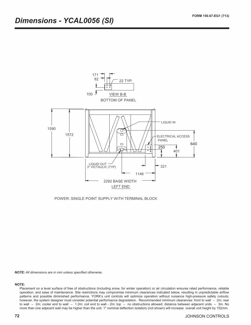
72
FORM 150.67-EG1 (713)
JOHNSON CONTROLS
Dimensions - YCAL0056 (SI)
NOTE: All dimensions are in mm unless specified otherwise.
250640
NOTE: Placement on a level surface of free of obstructions (including snow, for winter operation) or air circulation ensures rated performance, reliable
operation, and ease of maintenance. Site restrictions may compromise minimum clearances indicated below, resulting in unpredictable airflow patterns and possible diminished performance. YORK’s unit controls will optimize operation without nuisance high-pressure safety cutouts; however, the system designer must consider potential performance degradation. Recommended minimum clearances: front to wall – 2m; rear to wall – 2m; cooler end to wall – 1.2m; coil end to wall - 2m; top – no obstructions allowed; distance between adjacent units – 3m. No more than one adjacent wall may be higher than the unit. 1" nominal deflection isolators (not shown) will increase overall unit height by 152mm.
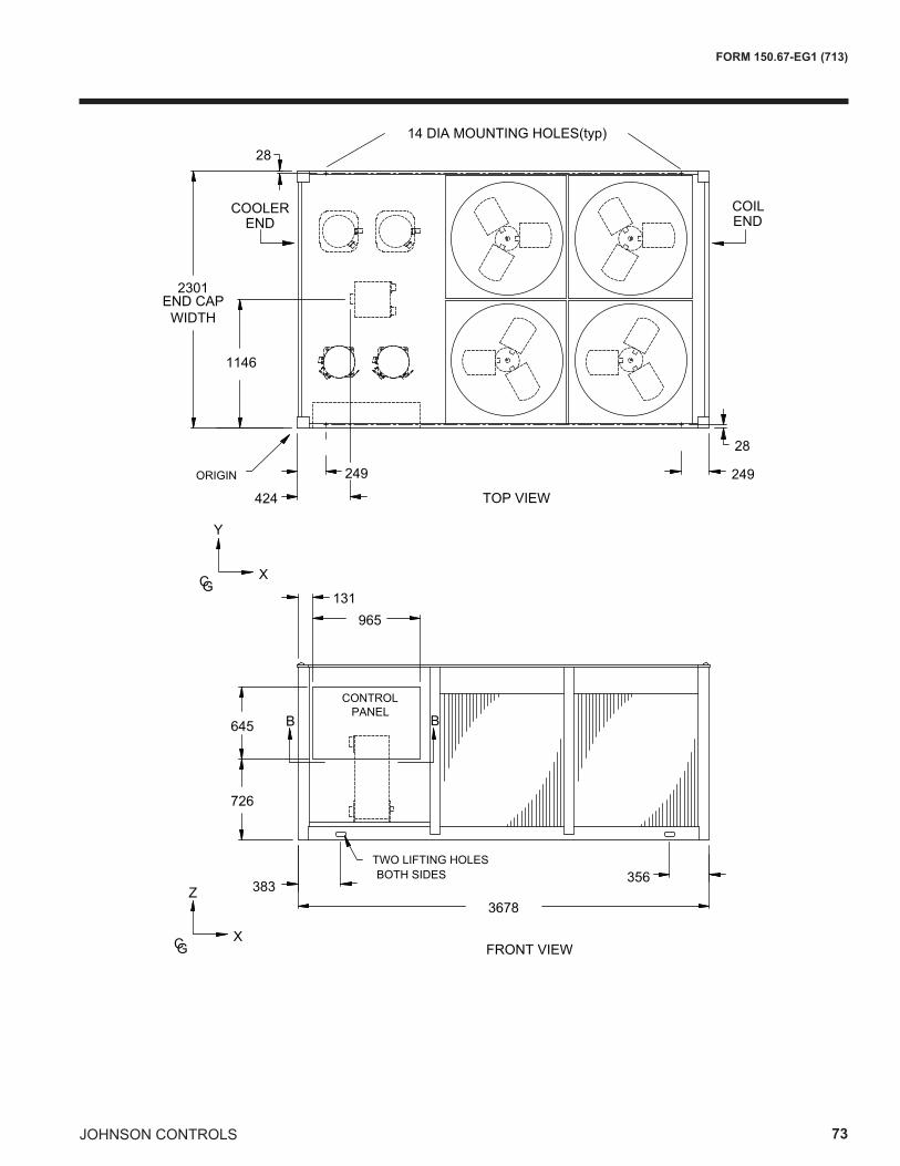
JOHNSON CONTROLS 73
FORM 150.67-EG1 (713)
2301
1146
Y
CGX
28
ORIGIN
END CAPWIDTH
424 TOP VIEW
249
28
249
14 DIA MOUNTING HOLES(typ)
3678383
356TWO LIFTING HOLES BOTH SIDES
FRONT VIEWCGX
Z
965131
645
726
B B
COILEND
COOLEREND
CONTROL PANEL
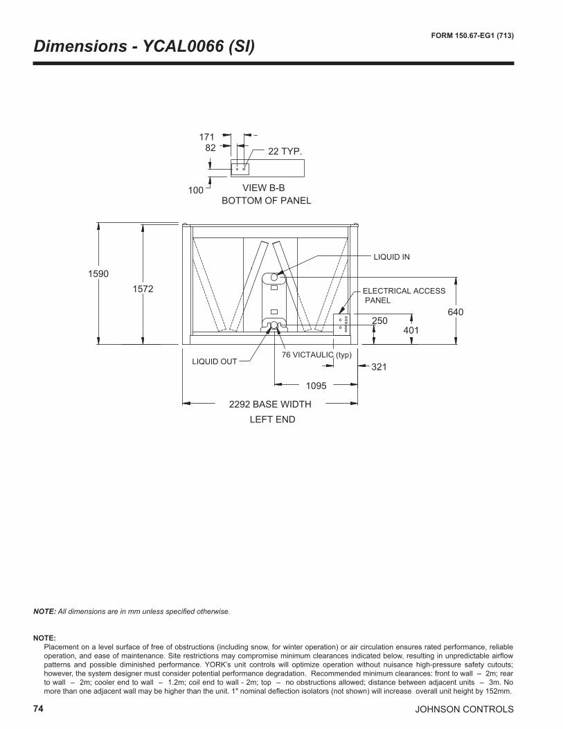
74
FORM 150.67-EG1 (713)
JOHNSON CONTROLS
Dimensions - YCAL0066 (SI)
15901572
640
401250
1095
32176 VICTAULIC (typ)
ELECTRICAL ACCESS PANEL
2292 BASE WIDTHLEFT END
LIQUID OUT
LIQUID IN
VIEW B-B
22 TYP.
100
82171
BOTTOM OF PANEL
NOTE: All dimensions are in mm unless specified otherwise.
NOTE: Placement on a level surface of free of obstructions (including snow, for winter operation) or air circulation ensures rated performance, reliable
operation, and ease of maintenance. Site restrictions may compromise minimum clearances indicated below, resulting in unpredictable airflow patterns and possible diminished performance. YORK’s unit controls will optimize operation without nuisance high-pressure safety cutouts; however, the system designer must consider potential performance degradation. Recommended minimum clearances: front to wall – 2m; rear to wall – 2m; cooler end to wall – 1.2m; coil end to wall - 2m; top – no obstructions allowed; distance between adjacent units – 3m. No more than one adjacent wall may be higher than the unit. 1" nominal deflection isolators (not shown) will increase overall unit height by 152mm.
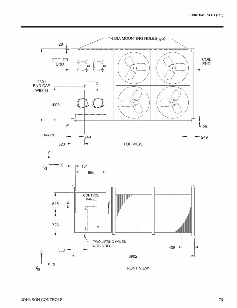
JOHNSON CONTROLS 75
FORM 150.67-EG1 (713)
2301
1095
323
965131
3902383
406
645
726
CONTROL PANEL
TWO LIFTING HOLES BOTH SIDES
Y
TOP VIEW
CGX
FRONT VIEWCGX
Z
28
28
ORIGIN 249 249
B B
14 DIA MOUNTING HOLES(typ)
END CAPWIDTH
COILEND
COOLEREND
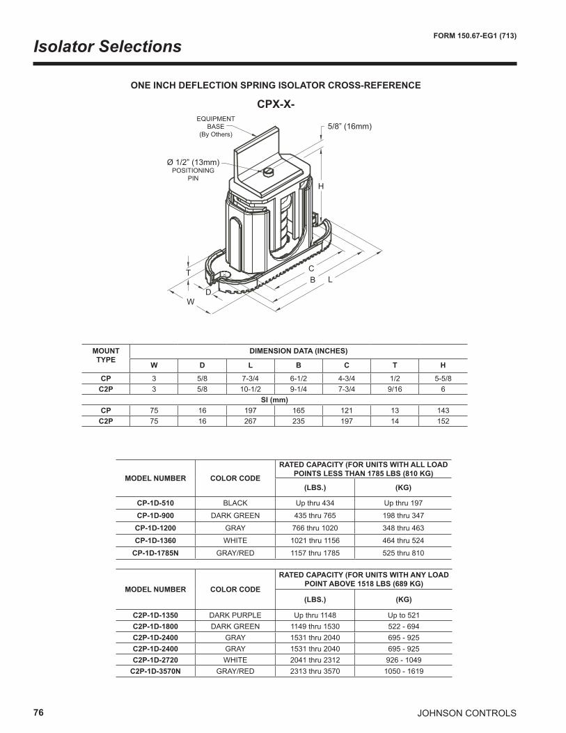
76
FORM 150.67-EG1 (713)
JOHNSON CONTROLS
Isolator Selections
ONE INCH DEFLECTION SPRING ISOLATOR CROSS-REFERENCE
CPX-X-
T
WD
H
LBC
5/8” (16mm)
Ø 1/2” (13mm)POSITIONING
PIN
EQUIPMENTBASE
(By Others)
MODEL NUMBER COLOR CODE
RATED CAPACITY (FOR UNITS WITH ALL LOAD POINTS LESS THAN 1785 LBS (810 KG)
(LBS.) (KG)
CP-1D-510 BLACK Up thru 434 Up thru 197
CP-1D-900 DARK GREEN 435 thru 765 198 thru 347
CP-1D-1200 GRAY 766 thru 1020 348 thru 463
CP-1D-1360 WHITE 1021 thru 1156 464 thru 524
CP-1D-1785N GRAY/RED 1157 thru 1785 525 thru 810
MODEL NUMBER COLOR CODE
RATED CAPACITY (FOR UNITS WITH ANY LOAD POINT ABOVE 1518 LBS (689 KG)
(LBS.) (KG)
C2P-1D-1350 DARK PURPLE Up thru 1148 Up to 521C2P-1D-1800 DARK GREEN 1149 thru 1530 522 - 694C2P-1D-2400 GRAY 1531 thru 2040 695 - 925C2P-1D-2400 GRAY 1531 thru 2040 695 - 925C2P-1D-2720 WHITE 2041 thru 2312 926 - 1049
C2P-1D-3570N GRAY/RED 2313 thru 3570 1050 - 1619
MOUNTTYPE
DIMENSION DATA (INCHES)
W D L B C T H
CP 3 5/8 7-3/4 6-1/2 4-3/4 1/2 5-5/8C2P 3 5/8 10-1/2 9-1/4 7-3/4 9/16 6
SI (mm)CP 75 16 197 165 121 13 143
C2P 75 16 267 235 197 14 152
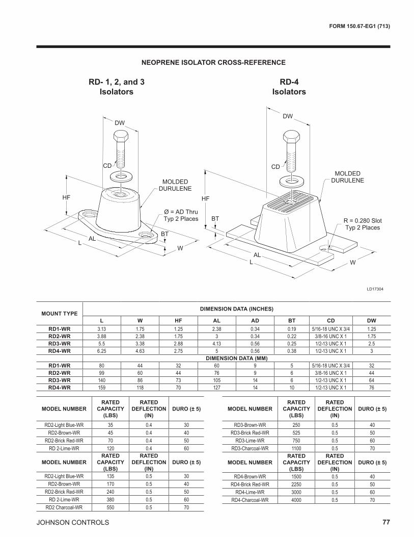
JOHNSON CONTROLS 77
FORM 150.67-EG1 (713)
NEOPRENE ISOLATOR CROSS-REFERENCE
LD17304
CDCD
HFHF
BT
BT
ALL
ALL
W
W
DWDW
MOLDEDDURULENEMOLDED
DURULENE
R = 0.280 SlotTyp 2 Places
Ø = AD ThruTyp 2 Places
RD- 1, 2, and 3Isolators
MOUNT TYPE DIMENSION DATA (INCHES)
L W HF AL AD BT CD DW RD1-WR 3.13 1.75 1.25 2.38 0.34 0.19 5/16-18 UNC X 3/4 1.25RD2-WR 3.88 2.38 1.75 3 0.34 0.22 3/8-16 UNC X 1 1.75RD3-WR 5.5 3.38 2.88 4.13 0.56 0.25 1/2-13 UNC X 1 2.5RD4-WR 6.25 4.63 2.75 5 0.56 0.38 1/2-13 UNC X 1 3
DIMENSION DATA (MM) RD1-WR 80 44 32 60 9 5 5/16-18 UNC X 3/4 32RD2-WR 99 60 44 76 9 6 3/8-16 UNC X 1 44RD3-WR 140 86 73 105 14 6 1/2-13 UNC X 1 64RD4-WR 159 118 70 127 14 10 1/2-13 UNC X 1 76
MODEL NUMBERRATED
CAPACITY (LBS)
RATED DEFLECTION
(IN)DURO (± 5)
RD2-Light Blue-WR 35 0.4 30RD2-Brown-WR 45 0.4 40
RD2-Brick Red-WR 70 0.4 50RD 2-Lime-WR 120 0.4 60
MODEL NUMBERRATED
CAPACITY (LBS)
RATED DEFLECTION
(IN)DURO (± 5)
RD2-Light Blue-WR 135 0.5 30RD2-Brown-WR 170 0.5 40
RD2-Brick Red-WR 240 0.5 50RD 2-Lime-WR 380 0.5 60
RD2 Charcoal-WR 550 0.5 70
MODEL NUMBERRATED
CAPACITY (LBS)
RATED DEFLECTION
(IN)DURO (± 5)
RD3-Brown-WR 250 0.5 40RD3-Brick Red-WR 525 0.5 50
RD3-Lime-WR 750 0.5 60RD3-Charcoal-WR 1100 0.5 70
MODEL NUMBERRATED
CAPACITY (LBS)
RATED DEFLECTION
(IN)DURO (± 5)
RD4-Brown-WR 1500 0.5 40RD4-Brick Red-WR 2250 0.5 50
RD4-Lime-WR 3000 0.5 60RD4-Charcoal-WR 4000 0.5 70
RD-4Isolators
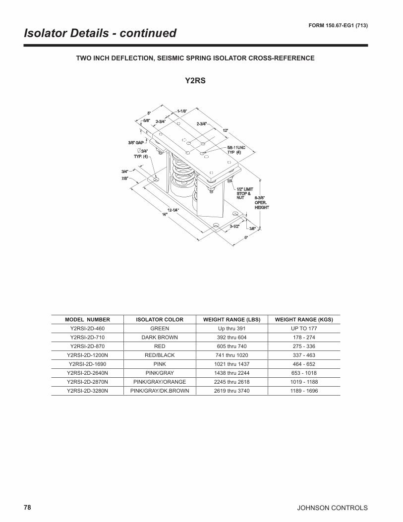
78
FORM 150.67-EG1 (713)
JOHNSON CONTROLS
Isolator Details - continued
TWO INCH DEFLECTION, SEISMIC SPRING ISOLATOR CROSS-REFERENCE
Y2RS
3/4”
7/8”
3/8” GAP
3/4”TYP. (4)
5/8” 2-3/4”
1-1/8”
2-3/4”
8P
4
8
STOP &8-3/8”OPER.HEIGHT
4
4
MODEL NUMBER ISOLATOR COLOR WEIGHT RANGE (LBS) WEIGHT RANGE (KGS)Y2RSI-2D-460 GREEN Up thru 391 UP TO 177
Y2RSI-2D-710 DARK BROWN 392 thru 604 178 - 274
Y2RSI-2D-870 RED 605 thru 740 275 - 336
Y2RSI-2D-1200N RED/BLACK 741 thru 1020 337 - 463
Y2RSI-2D-1690 PINK 1021 thru 1437 464 - 652
Y2RSI-2D-2640N PINK/GRAY 1438 thru 2244 653 - 1018
Y2RSI-2D-2870N PINK/GRAY/ORANGE 2245 thru 2618 1019 - 1188
Y2RSI-2D-3280N PINK/GRAY/DK.BROWN 2619 thru 3740 1189 - 1696

JOHNSON CONTROLS 79
FORM 150.67-EG1 (713)
INTENTIONALLY LEFT BLANK
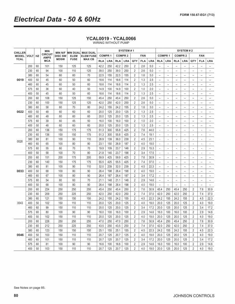
80
FORM 150.67-EG1 (713)
JOHNSON CONTROLS
Electrical Data - 50 & 60Hz
YCAL0019 - YCAL0066WIRING WITHOUT PUMP
See Notes on page 85.
CHILLERMODELYCAL
VOLT HZ
MINCIRCUIT
AMPSMCA
MIN N/FDISC SWMDSW
MIN DUALELEM FUSE
MAX DUALELEM FUSE
MAX CB
SYSTEM # 1 SYSTEM # 2
COMPR 1 COMPR 2 FAN COMPR 1 COMPR 2 FAN
RLA LRA RLA LRA QTY FLA LRA RLA LRA RLA LRA QTY FLA LRA
0019
200 60 101 150 125 125 42.2 250 42.2 250 2 2.6 5.0 – – – – – – –230 60 94 100 110 125 39.0 250 39.0 250 2 2.6 5.0 – – – – – – –380 60 54 60 60 70 22.5 155 22.5 155 2 1.6 3.0 – – – – – – –400 50 45 60 50 60 18.6 114 18.6 114 2 1.3 2.5 – – – – – – –460 60 45 60 50 60 18.6 114 18.6 114 2 1.3 2.5 – – – – – – –575 60 36 60 40 50 14.9 100 14.9 100 2 1.0 2.0 – – – – – – –400 50 45 60 50 60 18.6 114 18.6 114 2 1.3 2.5 – – – – – – –
0022
200 60 108 150 125 150 45.4 250 45.4 250 2 2.6 5.0 – – – – – – –230 60 100 150 125 125 42.0 250 42.0 250 2 2.6 5.0 – – – – – – –380 60 58 60 70 80 24.2 155 24.2 155 2 1.6 3.0 – – – – – – –400 50 48 60 60 60 20.0 125 20.0 125 2 1.3 2.5 – – – – – – –460 60 48 60 60 60 20.0 125 20.0 125 2 1.3 2.5 – – – – – – –575 60 39 60 45 50 16.0 100 16.0 100 2 1.0 2.0 – – – – – – –400 50 48 60 60 60 20.0 125 20.0 125 2 1.3 2.5 – – – – – – –
0028
200 60 136 150 175 175 51.3 300 55.8 425 2 7.6 44.0 - - - - - - -230 60 136 150 150 175 51.3 300 55.8 425 2 7.4 19.1 - - - - - - -380 60 81 100 90 110 26.9 139 36.0 239 2 4.5 23.1 - - - - - - -460 60 65 100 80 90 23.1 150 26.9 187 2 4.0 19.0 - - - - - - -575 60 55 60 70 70 19.9 109 23.7 148 2 2.9 15.3 - - - - - - -400 50 58 100 70 80 21.8 140 23.7 198 2 3.4 17.5 - - - - - - -
0033
200 60 151 200 175 200 59.9 425 59.9 425 2 7.6 30.9 – – – – – – –230 60 140 150 175 175 55.5 425 55.5 425 2 7.4 37.0 – – – – – – –380 60 81 100 90 110 32.0 239 32.0 239 2 4.5 22.3 – – – – – – –400 50 68 100 80 90 26.4 198 26.4 198 2 4.0 19.0 – – – – – – –460 60 67 100 80 90 26.4 187 26.4 187 2 3.4 17.2 – – – – – – –575 60 54 60 60 70 21.1 148 21.1 148 2 2.9 14.6 – – – – – – –400 50 68 100 80 90 26.4 198 26.4 198 2 4.0 19.0 – – – – – – –
0043
200 60 224 250 250 250 45.4 250 45.4 250 2 7.6 30.9 45.4 250 45.4 250 2 7.6 30.9230 60 209 250 225 250 42.0 250 42.0 250 2 7.4 37.0 42.0 250 42.0 250 2 7.4 37.0380 60 121 150 150 150 24.2 155 24.2 155 2 4.5 22.3 24.2 155 24.2 155 2 4.5 22.3400 50 102 150 110 110 20.0 125 20.0 125 2 4.0 19.0 20.0 125 20.0 125 2 4.0 19.0460 60 99 150 110 110 20.0 125 20.0 125 2 3.4 17.2 20.0 125 20.0 125 2 3.4 17.2575 60 80 100 90 90 16.0 100 16.0 100 2 2.9 14.6 16.0 100 16.0 100 2 2.9 14.6400 50 102 150 110 110 20.0 125 20.0 125 2 4.0 19.0 20.0 125 20.0 125 2 4.0 19.0
0046
200 60 228 250 250 250 47.0 250 47.0 250 2 7.6 30.9 45.4 250 45.4 250 2 7.6 30.9230 60 212 250 225 250 43.5 250 43.5 250 2 7.4 37.0 42.0 250 42.0 250 2 7.4 37.0380 60 123 150 150 150 25.1 155 25.1 155 2 4.5 22.3 24.2 155 24.2 155 2 4.5 22.3400 50 103 150 110 110 20.7 125 20.7 125 2 4.0 19.0 20.0 125 20.0 125 2 4.0 19.0460 60 101 150 110 110 20.7 125 20.7 125 2 3.4 17.2 20.0 125 20.0 125 2 3.4 17.2575 60 81 100 90 90 16.6 100 16.6 100 2 2.9 14.6 16.0 100 16.0 100 2 2.9 14.6400 50 103 150 110 110 20.7 125 20.7 125 2 4.0 19.0 20.0 125 20.0 125 2 4.0 19.0
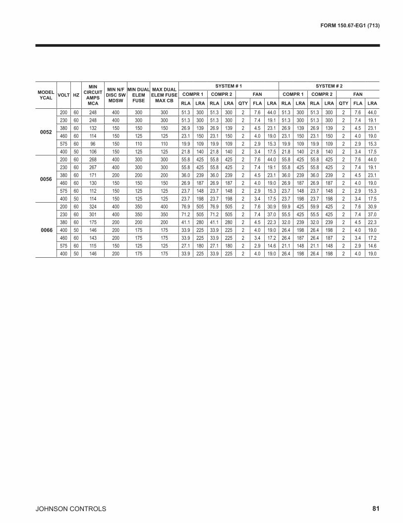
JOHNSON CONTROLS 81
FORM 150.67-EG1 (713)
MODELYCAL VOLT HZ
MINCIRCUIT
AMPSMCA
MIN N/FDISC SWMDSW
MIN DUALELEM FUSE
MAX DUALELEM FUSE
MAX CB
SYSTEM # 1 SYSTEM # 2
COMPR 1 COMPR 2 FAN COMPR 1 COMPR 2 FAN
RLA LRA RLA LRA QTY FLA LRA RLA LRA RLA LRA QTY FLA LRA
0052
200 60 248 400 300 300 51.3 300 51.3 300 2 7.6 44.0 51.3 300 51.3 300 2 7.6 44.0230 60 248 400 300 300 51.3 300 51.3 300 2 7.4 19.1 51.3 300 51.3 300 2 7.4 19.1380 60 132 150 150 150 26.9 139 26.9 139 2 4.5 23.1 26.9 139 26.9 139 2 4.5 23.1460 60 114 150 125 125 23.1 150 23.1 150 2 4.0 19.0 23.1 150 23.1 150 2 4.0 19.0575 60 96 150 110 110 19.9 109 19.9 109 2 2.9 15.3 19.9 109 19.9 109 2 2.9 15.3400 50 106 150 125 125 21.8 140 21.8 140 2 3.4 17.5 21.8 140 21.8 140 2 3.4 17.5
0056
200 60 268 400 300 300 55.8 425 55.8 425 2 7.6 44.0 55.8 425 55.8 425 2 7.6 44.0230 60 267 400 300 300 55.8 425 55.8 425 2 7.4 19.1 55.8 425 55.8 425 2 7.4 19.1380 60 171 200 200 200 36.0 239 36.0 239 2 4.5 23.1 36.0 239 36.0 239 2 4.5 23.1460 60 130 150 150 150 26.9 187 26.9 187 2 4.0 19.0 26.9 187 26.9 187 2 4.0 19.0575 60 112 150 125 125 23.7 148 23.7 148 2 2.9 15.3 23.7 148 23.7 148 2 2.9 15.3400 50 114 150 125 125 23.7 198 23.7 198 2 3.4 17.5 23.7 198 23.7 198 2 3.4 17.5
0066
200 60 324 400 350 400 76.9 505 76.9 505 2 7.6 30.9 59.9 425 59.9 425 2 7.6 30.9230 60 301 400 350 350 71.2 505 71.2 505 2 7.4 37.0 55.5 425 55.5 425 2 7.4 37.0380 60 175 200 200 200 41.1 280 41.1 280 2 4.5 22.3 32.0 239 32.0 239 2 4.5 22.3400 50 146 200 175 175 33.9 225 33.9 225 2 4.0 19.0 26.4 198 26.4 198 2 4.0 19.0460 60 143 200 175 175 33.9 225 33.9 225 2 3.4 17.2 26.4 187 26.4 187 2 3.4 17.2575 60 115 150 125 125 27.1 180 27.1 180 2 2.9 14.6 21.1 148 21.1 148 2 2.9 14.6400 50 146 200 175 175 33.9 225 33.9 225 2 4.0 19.0 26.4 198 26.4 198 2 4.0 19.0
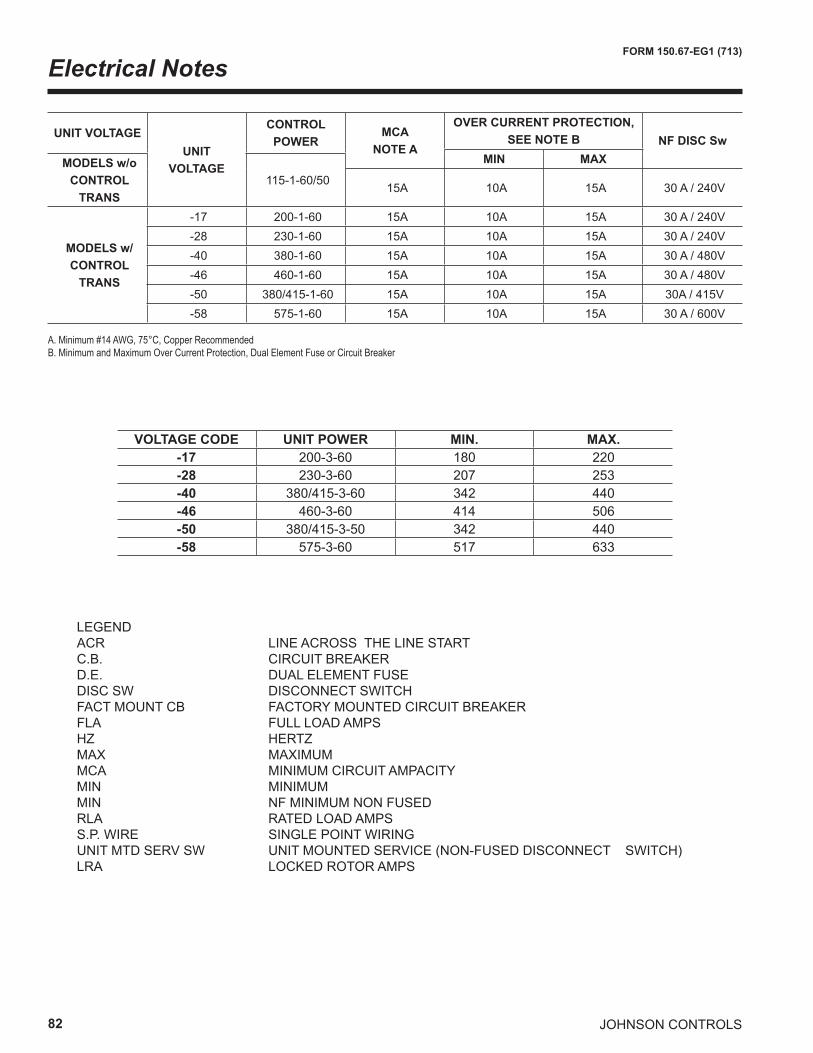
82
FORM 150.67-EG1 (713)
JOHNSON CONTROLS
Electrical Notes
VOLTAGE CODE UNIT POWER MIN. MAX.-17 200-3-60 180 220-28 230-3-60 207 253-40 380/415-3-60 342 440-46 460-3-60 414 506-50 380/415-3-50 342 440-58 575-3-60 517 633
UNIT VOLTAGEUNIT
VOLTAGE
CONTROL POWER
MCANOTE A
OVER CURRENT PROTECTION,SEE NOTE B NF DISC Sw
MIN MAXMODELS w/oCONTROL
TRANS115-1-60/50 15A 10A 15A 30 A / 240V
MODELS w/CONTROL
TRANS
-17 200-1-60 15A 10A 15A 30 A / 240V-28 230-1-60 15A 10A 15A 30 A / 240V-40 380-1-60 15A 10A 15A 30 A / 480V-46 460-1-60 15A 10A 15A 30 A / 480V-50 380/415-1-60 15A 10A 15A 30A / 415V-58 575-1-60 15A 10A 15A 30 A / 600V
A. Minimum #14 AWG, 75°C, Copper RecommendedB. Minimum and Maximum Over Current Protection, Dual Element Fuse or Circuit Breaker
LEGEND ACR LINE ACROSS THE LINE START C.B. CIRCUIT BREAKER D.E. DUAL ELEMENT FUSE DISC SW DISCONNECT SWITCH FACT MOUNT CB FACTORY MOUNTED CIRCUIT BREAKER FLA FULL LOAD AMPS HZ HERTZ MAX MAXIMUM MCA MINIMUM CIRCUIT AMPACITY MIN MINIMUM MIN NF MINIMUM NON FUSED RLA RATED LOAD AMPS S.P. WIRE SINGLE POINT WIRING UNIT MTD SERV SW UNIT MOUNTED SERVICE (NON-FUSED DISCONNECT SWITCH) LRA LOCKED ROTOR AMPS
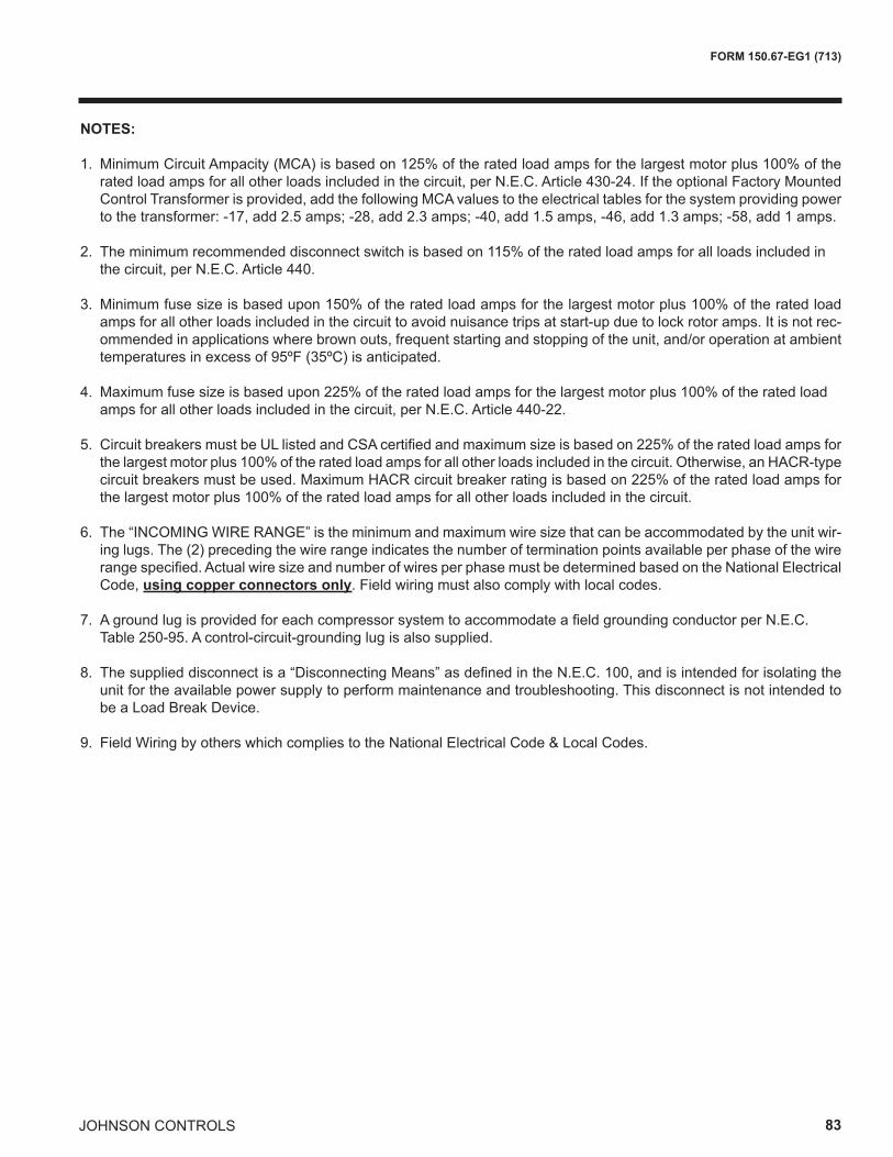
JOHNSON CONTROLS 83
FORM 150.67-EG1 (713)
NOTES:
1. Minimum Circuit Ampacity (MCA) is based on 125% of the rated load amps for the largest motor plus 100% of the rated load amps for all other loads included in the circuit, per N.E.C. Article 430-24. If the optional Factory Mounted Control Transformer is provided, add the following MCA values to the electrical tables for the system providing power to the transformer: -17, add 2.5 amps; -28, add 2.3 amps; -40, add 1.5 amps, -46, add 1.3 amps; -58, add 1 amps.
2. The minimum recommended disconnect switch is based on 115% of the rated load amps for all loads included in the circuit, per N.E.C. Article 440.
3. Minimum fuse size is based upon 150% of the rated load amps for the largest motor plus 100% of the rated load amps for all other loads included in the circuit to avoid nuisance trips at start-up due to lock rotor amps. It is not rec-ommended in applications where brown outs, frequent starting and stopping of the unit, and/or operation at ambient temperatures in excess of 95ºF (35ºC) is anticipated.
4. Maximum fuse size is based upon 225% of the rated load amps for the largest motor plus 100% of the rated load amps for all other loads included in the circuit, per N.E.C. Article 440-22.
5. Circuit breakers must be UL listed and CSA certified and maximum size is based on 225% of the rated load amps for the largest motor plus 100% of the rated load amps for all other loads included in the circuit. Otherwise, an HACR-type circuit breakers must be used. Maximum HACR circuit breaker rating is based on 225% of the rated load amps for the largest motor plus 100% of the rated load amps for all other loads included in the circuit.
6. The “INCOMING WIRE RANGE” is the minimum and maximum wire size that can be accommodated by the unit wir-ing lugs. The (2) preceding the wire range indicates the number of termination points available per phase of the wire range specified. Actual wire size and number of wires per phase must be determined based on the National Electrical Code, using copper connectors only. Field wiring must also comply with local codes.
7. A ground lug is provided for each compressor system to accommodate a field grounding conductor per N.E.C. Table 250-95. A control-circuit-grounding lug is also supplied.
8. The supplied disconnect is a “Disconnecting Means” as defined in the N.E.C. 100, and is intended for isolating the unit for the available power supply to perform maintenance and troubleshooting. This disconnect is not intended to be a Load Break Device.
9. Field Wiring by others which complies to the National Electrical Code & Local Codes.
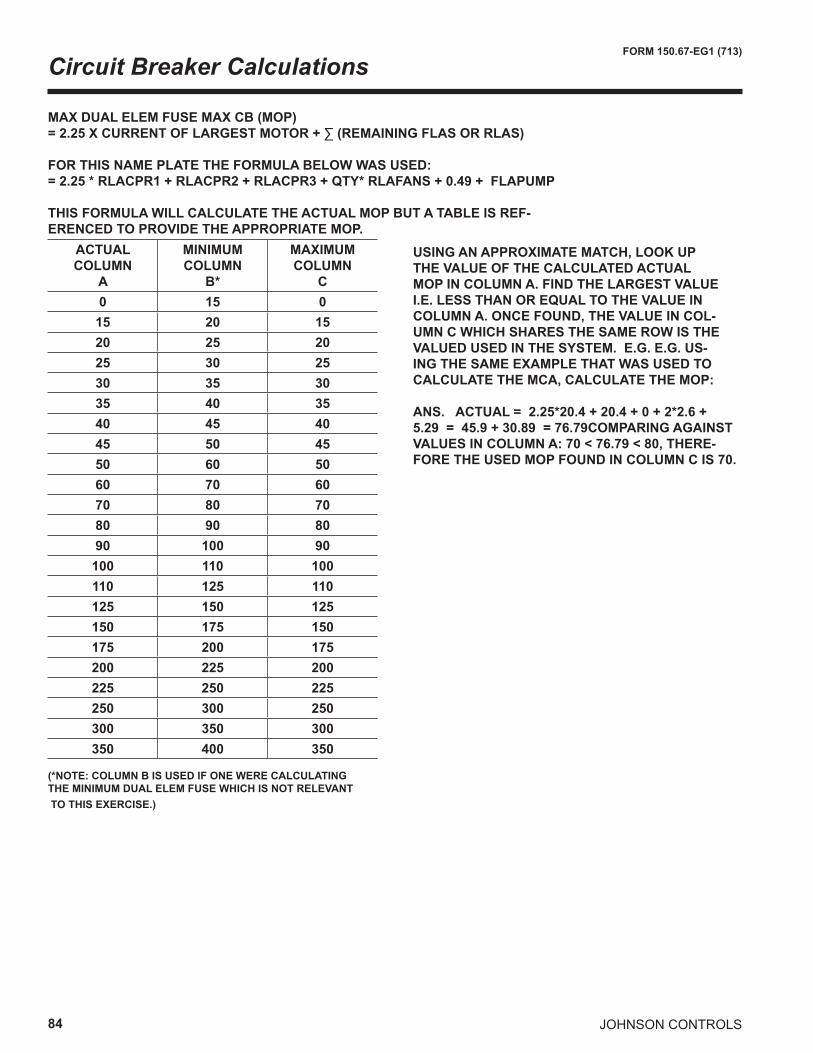
84
FORM 150.67-EG1 (713)
JOHNSON CONTROLS
Circuit Breaker Calculations
MAX DUAL ELEM FUSE MAX CB (MOP)=2.25XCURRENTOFLARGESTMOTOR+∑(REMAININGFLASORRLAS)
FOR THIS NAME PLATE THE FORMULA BELOW WAS USED:= 2.25 * RLACPR1 + RLACPR2 + RLACPR3 + QTY* RLAFANS + 0.49 + FLAPUMP
THIS FORMULA WILL CALCULATE THE ACTUAL MOP BUT A TABLE IS REF-ERENCED TO PROVIDE THE APPROPRIATE MOP.
ACTUALCOLUMN
A
MINIMUMCOLUMN
B*
MAXIMUMCOLUMN
C0 15 0
15 20 1520 25 2025 30 2530 35 3035 40 3540 45 4045 50 4550 60 5060 70 6070 80 7080 90 8090 100 90
100 110 100110 125 110125 150 125150 175 150175 200 175200 225 200225 250 225250 300 250300 350 300350 400 350
(*NOTE: COLUMN B IS USED IF ONE WERE CALCULATING THE MINIMUM DUAL ELEM FUSE WHICH IS NOT RELEVANT TO THIS EXERCISE.)
USING AN APPROXIMATE MATCH, LOOK UP THE VALUE OF THE CALCULATED ACTUAL MOP IN COLUMN A. FIND THE LARGEST VALUE I.E. LESS THAN OR EQUAL TO THE VALUE IN COLUMN A. ONCE FOUND, THE VALUE IN COL-UMN C WHICH SHARES THE SAME ROW IS THE VALUED USED IN THE SYSTEM. E.G. E.G. US-ING THE SAME EXAMPLE THAT WAS USED TO CALCULATE THE MCA, CALCULATE THE MOP:
ANS. ACTUAL = 2.25*20.4 + 20.4 + 0 + 2*2.6 + 5.29 = 45.9 + 30.89 = 76.79COMPARING AGAINST VALUES IN COLUMN A: 70 < 76.79 < 80, THERE-FORE THE USED MOP FOUND IN COLUMN C IS 70.
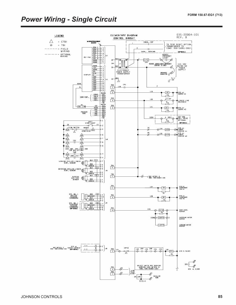
JOHNSON CONTROLS 85
FORM 150.67-EG1 (713)
Power Wiring - Single Circuit
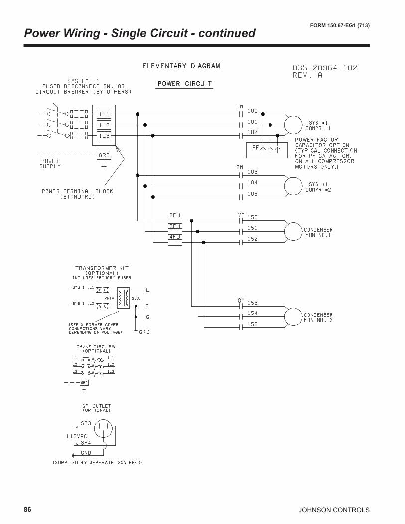
86
FORM 150.67-EG1 (713)
JOHNSON CONTROLS
Power Wiring - Single Circuit - continued
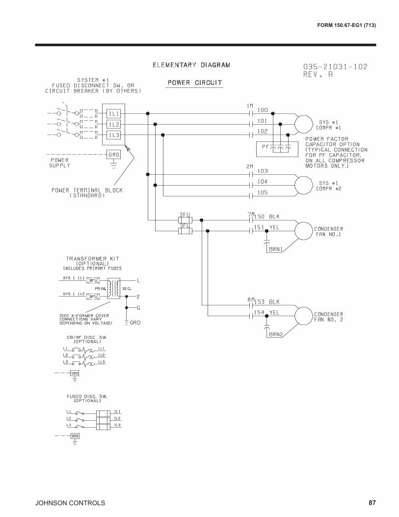
JOHNSON CONTROLS 87
FORM 150.67-EG1 (713)
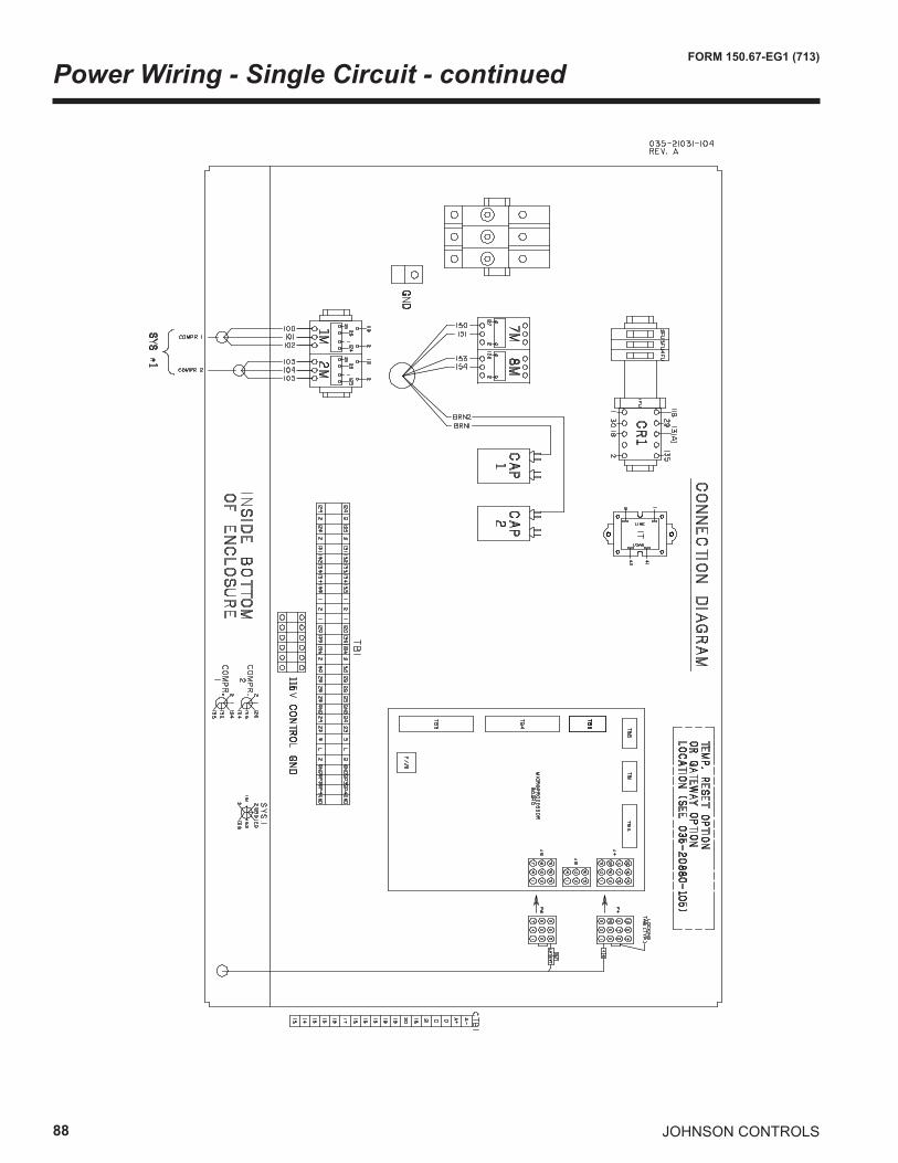
88
FORM 150.67-EG1 (713)
JOHNSON CONTROLS
Power Wiring - Single Circuit - continued
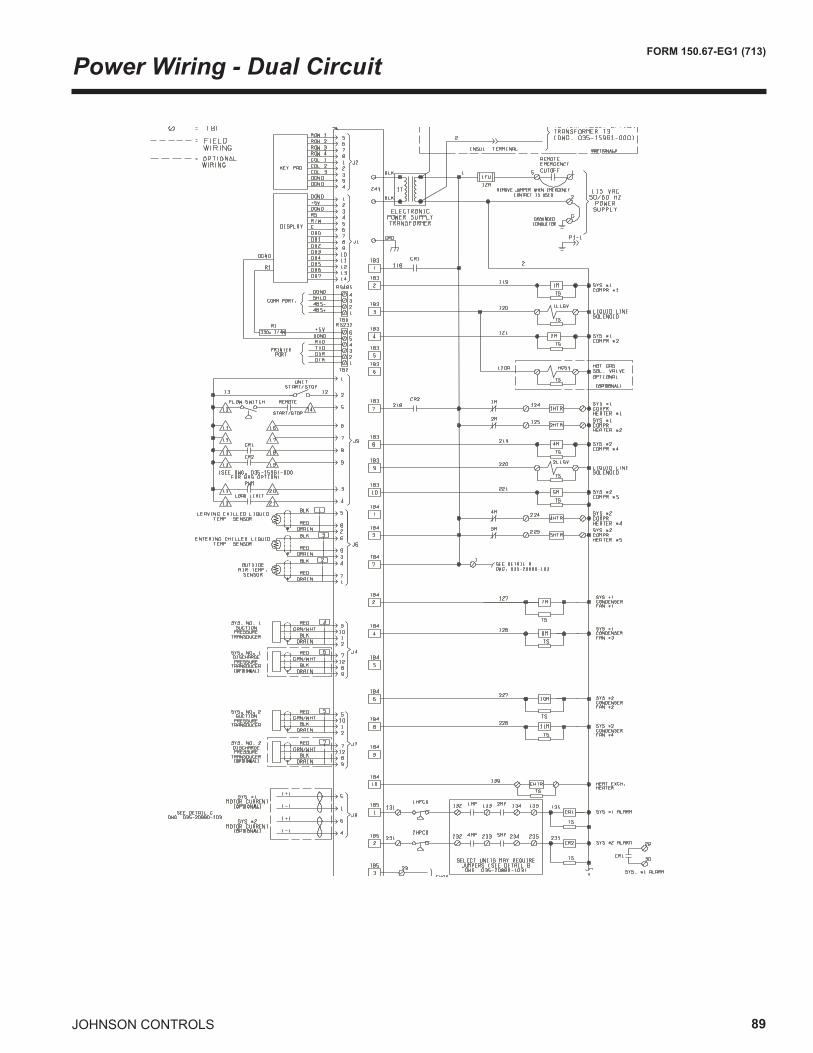
JOHNSON CONTROLS 89
FORM 150.67-EG1 (713)
Power Wiring - Dual Circuit
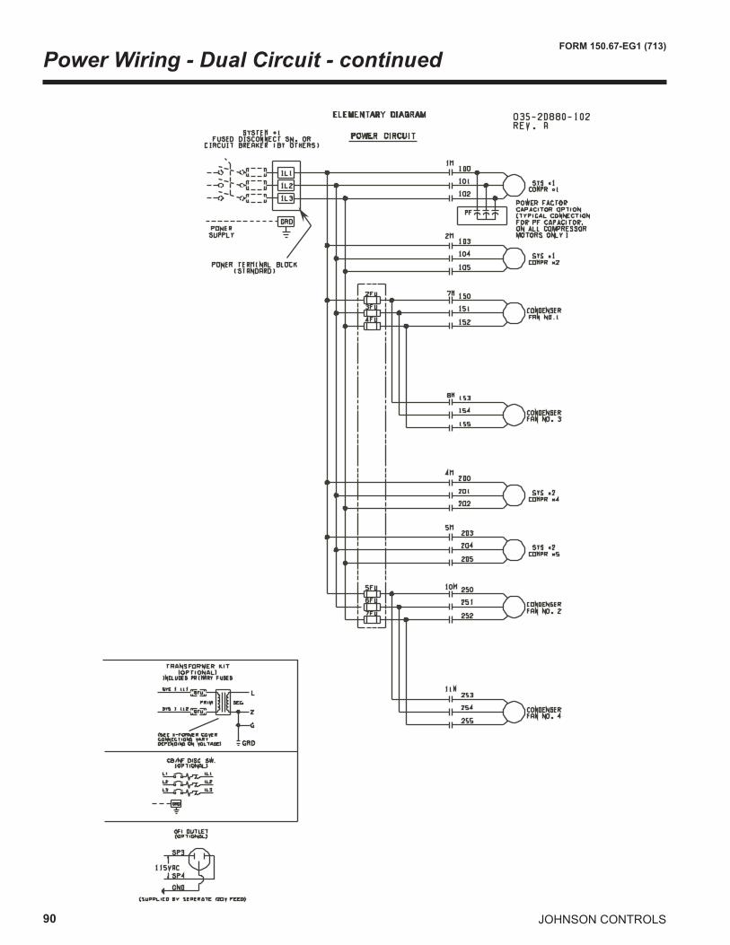
90
FORM 150.67-EG1 (713)
JOHNSON CONTROLS
Power Wiring - Dual Circuit - continued
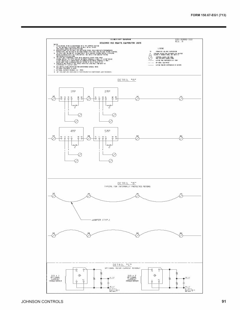
JOHNSON CONTROLS 91
FORM 150.67-EG1 (713)
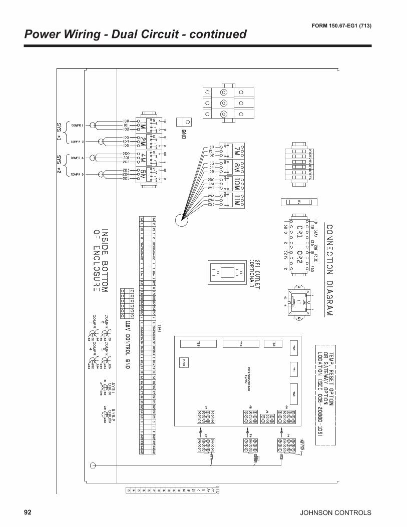
92
FORM 150.67-EG1 (713)
JOHNSON CONTROLS
Power Wiring - Dual Circuit - continued
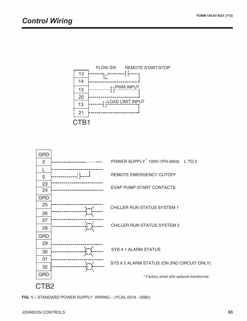
JOHNSON CONTROLS 93
FORM 150.67-EG1 (713)
FIG. 1 – STANDARD POWER SUPPLY WIRING – (YCAL 0014 - 0080)
CTB121
132013
1413
FLOW SW REMOTE START/STOP
PWM INPUT
LOAD LIMIT INPUT
*
* Factory wired with optional transformer.
Control Wiring
94
FORM 150.67-EG1 (713)
JOHNSON CONTROLS
Application Data
UNIT LOCATION
The YCAL chillers are designed for outdoor installation. When selecting a site for installation, be guided by the following conditions:
1. For outdoor locations of the unit, select a place having an adequate supply of fresh air for the condenser.
2. Avoid locations beneath windows or between struc-tures where normal operating sounds may be objec-tionable.
3. Installation sites may be either on a roof, or at ground level. (See FOUNDATION.)
4. The condenser fans are the propeller-type, and are not recommended for use with duct work in the condenser air stream.
5. When it is desirable to surround the unit(s), it is rec-ommended that the screening be able to pass the required chiller CFM without exceeding 0.1” of water external static pressure.
6. Protection against corrosive environments is available by supplying the units with either copper fin, cured epoxy-dipped, or epoxy-coated fins on the condenser coils. The epoxy-dipped or epoxy-coated coils should be offered with any units being installed at the sea-shore or where salt spray may hit the unit.
In installations where winter operation is intended and snow accumulations are expected, additional height must be provided to ensure normal condenser air flow.
Recommended clearances for units are given in DIMEN-SIONS. When the available space is less, the unit(s) must be equipped with the discharge pressure transducer op-tion to permit high pressure unloading in the event that air recirculation were to occur.
FOUNDATION
The unit should be mounted on a flat and level foundation, ground or roof, capable of supporting the entire operating weight of the equipment. Operating weights are given in the PHYSICAL DATA tables.
ROOF LOCATIONS – Choose a spot with adequate struc-tural strength to safely support the entire weight of the unit and service personnel. Care must be taken not to damage the roof during installation. If the roof is “bonded”, consult the building contractor or architect for special installation requirements. Roof installations should incorporate the use of spring-type isolators to minimize the transmission
of vibration into the building structure.
GROUND LEVEL INSTALLATIONS – It is important that the units be installed on a substantial base that will not settle, causing strain on the liquid lines and resulting in possible leaks. A one-piece concrete slab with footers extending below the frost line is highly recommended. Ad-ditionally, the slab should not be tied to the main building foundation, as noises will telegraph.
Mounting holes (11/16” diameter) are provided in the steel channel for bolting the unit to its foundation. See DIMENSIONS.
For ground level installations, precautions should be taken to protect the unit from tampering by or injury to unau-thorized persons. Screws on access panels will prevent casual tampering; however, further safety precautions, such as unit enclosure options, a fenced-in enclosure, or locking devices on the panels may be advisable. Check local authorities for safety regulations.
CHILLED LIQUID PIPING
The chilled liquid piping system should be laid out so that the circulating pump discharges into the cooler. The inlet and outlet cooler liquid connections are given in DIMEN-SIONS.
Hand stop valves are recommended for use in all lines to facilitate servicing. Drain connections should be provided at all low points to permit complete drainage of the cooler and system piping.
The cooler must be protected by a strainer, preferablyof 40 mesh, fitted as close as possible to the liquid inletconnection, and provided with a means of local isolation.
The cooler must not be exposed to flushing velocities ordebris released during flushing. It is recommended that asuitably sized bypass and valve arrangement is installedto allow flushing of the piping system. The bypass can beused during maintenance to isolate the heat exchangerwithout disrupting flow to other units.
Pressure gauge connections are recommended for instal-lation in the inlet and outlet water lines. Gauges are not furnished with the unit and are to be furnished by other suppliers.
The chilled liquid lines that are exposed to outdoor ambi-ents should be wrapped with a supplemental heater cable and covered with insulation. As an alternative, ethylene glycol should be added to protect against freezeup during low ambient periods.
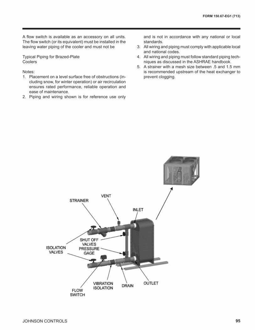
JOHNSON CONTROLS 95
FORM 150.67-EG1 (713)
A flow switch is available as an accessory on all units. The flow switch (or its equivalent) must be installed in the leaving water piping of the cooler and must not be
Typical Piping for Brazed-PlateCoolers Notes:1. Placement on a level surface free of obstructions (in-
cluding snow, for winter operation) or air recirculation ensures rated performance, reliable operation and ease of maintenance.
2. Piping and wiring shown is for reference use only
and is not in accordance with any national or local standards.
3. All wiring and piping must comply with applicable local and national codes.
4. All wiring and piping must follow standard piping tech-niques as discussed in the ASHRAE handbook.
5. A strainer with a mesh size between .5 and 1.5 mm is recommended upstream of the heat exchanger to prevent clogging.
96
FORM 150.67-EG1 (713)
JOHNSON CONTROLS
Guide Specifications
PART 1 – GENERAL
1.01 SCOPE
A. The requirements of the General Conditions, Supple-mentary Conditions, Division 1, and Drawings apply to all Work herein.
B. Provide Microprocessor controlled, multiple-scroll compressor, air-cooled, liquid chillers of the scheduled capacities as shown and indicated on the Drawings, including but not limited to:
1. Chiller package
2. Electrical power and control connections
3. Chilled water connections
4. Change of refrigerant oil (for factory mounted evaporator) or (evaporator shipped separately for field installation and piping by contractor)
1.02 QUALITY ASSURANCE
A. Products shall be Designed, Tested, Rated and Certified in accordance with, and installed in compli-ance with applicable sections of the following Stan-dards and Codes:
1. ANSI/ASHRAE Standard 15 – Safety Code for Mechanical Refrigeration
2. ASHRAE 90.1– Energy Efficiency compliance.
3. ANSI/NFPA Standard 70 – National Electrical Code (N.E.C.).
4. ASME Boiler & Pressure Vessel Code, Section VIII, Division 1.
5. ARI Standard 550/590 – Positive Displacement Compressors and Air Cooled Rotary Screw Water-Chilling Packages.
6. Conform to Intertek Testing Services, formerly ETL, for construction of chillers and provide ETL/cETL Listing label.
7. Manufactured in facility registered to ISO9002.
8. OSHA - Occupational Safety and Health Act
B. Factory Test: Chiller shall be pressure-tested, evacuated and fully charged with refrigerant and oil, and shall be factory operational run tested with water flowing through the vessel.
C. Chiller manufacturer shall have a factory trained and supported service organization that is within a 50 mile radius of the site.
D. Manufacturer shall Warrant all equipment and material of its manufacture against defects in workmanship and material for a period of one year from date of initial start-up or eighteen (18) months from date of shipment, whichever occurs first.
1.03 DELIVERY AND HANDLING
A. Unit shall be delivered to job site fully assembled, and charged with refrigerant and oil by the Manufacturer. (Contractor is responsible for providing and installing the refrigerant charge including the charge required for the field installed interconnecting piping. Chiller components shall ship with a dry nitrogen holding charge – Remote Evaporator option).
B. Unit shall be stored and handled per Manufacturer’s instructions.
PART 2 - PRODUCTS
2.01 CHILLER MATERIALS AND COMPONENTS
A. General: Install and commission, as shown on the schedules and plans, factory assembled, charged, and tested air cooled scroll compressor chiller(s) as specified herein. Chiller shall be designed, selected, and constructed using a refrigerant with Flammability rating of “1”, as defined by ANSI/ASHRAE STAN-DARD - 34 Number Designation and Safety Classifi-cation of Refrigerants. Chiller shall include, but is not limited to a complete system with a single refrigerant circuit 35 tons (123kW) and below, and not less than two refrigerant circuits above 35 tons (123kW), scroll compressors, direct expansion type evaporator, air-cooled condenser, refrigerant, lubrication system, interconnecting wiring, safety and operating controls including capacity controller, control center, motor starting components, and special features as speci-fied herein or required for safe, automatic operation.
B. Cabinet: External structural members shall be con-structed of heavy gauge, galvanized steel coated with baked on powder paint which, when subject to ASTM B117, 1000 hour, 5% salt spray test, yields minimum ASTM 1654 rating of “6”. Add Wire Panels of heavy gauge, welded wire-mesh, coated to resist corrosion, to protect condenser coils from incidental damage and restrict unauthorized access to internal components. Factory installed.
JOHNSON CONTROLS 97
FORM 150.67-EG1 (713)
2.02 COMPRESSORS
Compressors: Shall be hermetic, scroll-type, including:
1. Compliant design with axial and radial sealing.
2. Refrigerant flow through the compressor with 100% suction cooled motor.
3. Large suction side free volume and oil sump to provide liquid handling capability.
4. Compressor crankcase heaters to provide extra liquid migration protection.
5. Annular discharge check valve and reverse vent assembly to provide low pressure drop, silent shutdown and reverse rotation protection.
6. Initial Oil charge.
7. Oil Level sightglass.
8. Vibration isolator mounts for compressors.
9. Brazed-type connections for fully hermetic refriger-ant circuits.
2.03 REFRIGERANT CIRCUIT COMPONENTS
Each refrigerant circuit shall include liquid line shutoff valve with charging port, low side pressure relief device, filter-drier, solenoid valve, sight glass with moisture indi-cator, expansion valves, and flexible, closed-cell foam insulated suction line. Unit also includes service isolation valves as standard.
2.04 HEAT EXCHANGERS
A. Evaporator:
1. Evaporator shall be brazed-plate stainless steel construction, single or dual circuit heat exchang-ers capable of refrigerant working pressure of 650 psig (3103 kPa) and liquid side pressure of 150 psig (1034 kPa) (Option for 300 psig [2068 kPa] available.)
2. Evaporator shall be covered in 3/4" (19mm) flex-ible, closed cell insulation, thermal conductivity of 0.26k (BTU/HR-FT2-°F]/in.) maximum.
3. Cooler shall have thermostaticaly controlled heat-ers to protect to -20°F (29°C) ambient in off-cycle.
4. Brazed plate heat exchangers shall be UL listed.
5. Installing contractor must include accomodations in the chilled water piping to allow proper drainage and venting of the heat exchanger. A strainer with a mesh size between 0.5 and 1.5mm (40 mesh) is recommended upstream of the heat exchanger to prevent clogging.
B. Air Cooled Condenser:
1. Coils: Internally enhanced, seamless copper tubes, mechanically expanded into aluminum alloy fins with full height collars. Subcooling coil an integral part of condenser. Design working pressure shall be 650 PSIG (45 barg).
2. Low Noise Fans: Shall be dynamically and stati-cally balanced, direct drive, propeller type fan, pro-viding vertical air discharge and low sound. Each fan in its own compartment to prevent crossflow during fan cycling. Guards of heavy gauge, PVC (polyvinylchloride) coated or galvanized steel.
3. Fan Motors: High efficiency, direct drive, 6 pole, 3 phase, insulation class “F”, current protected, Total ly Enclosed Air-Over (TEAO), r igid mounted, with double sealed, permanently lu- bricated, ball bearings.
2.05 CONTROLS
A. General: Automatic start, stop, operating, and pro-tection sequences across the range of scheduled conditions and transients.
B. Microprocessor Enclosure: Rain and dust tight NEMA 3R/12 powder painted steel cabinet with a gasket sealed protective cover.
C. Microprocessor Control Center:
1. Automatic control of compressor start/stop, anti-coincidence and anti-recycle timers, automatic pump-down on shutdown, condenser fans, evapo-rator pump, evaporator heater, unit alarm contacts, and chiller operation from 0°F to 125°F (-18°C to 52°C) ambient. Automatic reset to normal chiller operation after power failure.
2. Remote water temperature reset via a Pulse Width Modulated (PWM) input signal or up to two steps of demand (load) limiting.
3. Software stored in non-volatile memory, with programmed setpoints retained in lithium bat- tery backed real time clock (RTC) memory for minimum 5 years.
98
FORM 150.67-EG1 (713)
JOHNSON CONTROLS
4. Forty character liquid crystal display, descrip- tions in English (or Spanish, French, Italian, or German), numeric data in English (or Metric) units. Sealed keypad with sections for Setpoints, Display/Print, Entry, Unit Options & clock, and On/Off Switch.
5. Programmable Setpoints (within Manufacturer limits): display language; chilled liquid tempera- ture setpoint and range, remote reset tempera- ture range, set daily schedule/holiday for start/ stop, manual override for servicing, low and high AMBIENT °Cutouts, number of compressors, low liquid temperature cutout, low suction pressure cutout, high discharge pressure cutout, anti-re- cycle timer (compressor start cycle time), and anti-coincident timer (delay compressor starts).
6. Display Data: Return and leaving liquid tem- peratures, low leaving liquid temperature cut- out setting, low ambient temperature cutout set- ting, outdoor air temperature, English or metric data, suction pressure cutout setting, each system suction pressure, discharge pres-sure (standard on YCAL0019-0066 models), liquid temperature reset via a Johnson Controls ISN DDCor Building Automation System (by others) via PWM input as standard or a 4-20milliamp or 0- 10 VDC input or contact closure with optional BAS interface, anti-recycle timer status for each compressor, anti-coincident system start timer condition, compressor run status, no cooling load condition, day, date and time, daily start/ stop times, holiday status, automatic or manual system lead/lag control, lead system definition, compressor starts/operating hours (each), sta- tus of hot gas valves, evaporator heater and fan operation, run permissive status, number of compressors running, liquid solenoid valve status, load & unload timer status, water pump status.
7. System Safeties: Shall cause individual com pressor systems to perform auto shut down; manual reset required after the third trip in 90 minutes. Includes: high discharge pressure, low suction pressure, high pressure switch, and motor protector. Compressor motor protector shall protect against damage due to high input current or thermal overload of windings.
8. Unit Safeties: Shall be automatic reset and cause compressors to shut down if low ambi- ent, low leaving chilled liquid temperature, un-
der voltage, and flow switch operation. Contrac- tor shall provide flow switch and wiring per chiller manufacturer requirements.
9. Alarm Contacts: Low ambient, low leaving chilled liquid temperature, low voltage, low battery, and (per compressor circuit): high dis- charge pressure, and low suction pressure.
D. Manufacturer shall provide any controls not listed above, necessary for automatic chiller operation. Me-chanical Contractor shall provide field control wiring necessary to interface sensors to the chiller control system.
2.06 POWER CONNECTION AND DISTRIBUTION
A. Power Panels:
1. NEMA 3R, powder painted steel cabinets with a gasketed protective cover. Provide main power connection(s), control power connections, com-pressor and fan motor start contactors, current overloads, and factory wiring.
2. Power supply shall enter unit at a single loca- tion, be 3 phase of scheduled voltage, and connect to individual terminal blocks per com-pressor. Separate disconnecting means and/ or external branch circuit protection (by Con- tractor) required per applicable local or national codes.
B. Compressor, control and fan motor power wiring shall be fully contained within the unit enclosure, or shall be routed through liquid tight conduit.
2.07 ACCESSORIES AND OPTIONS
Some accessories and options supercede standard prod-uct features. Your Johnson Controls representative will be pleased to provide assistance.
A. Microprocessor controlled, Factory installed Across-the-Line type compressor motor starters as standard.
B. Outdoor Ambient Temperature Control
1. Low Ambient Control: Permits unit operation to 0°F ambient.
2. High AMBIENT Control: Permits unit operation above 115°F ambient.
Guide Specifications – continued
JOHNSON CONTROLS 99
FORM 150.67-EG1 (713)
C. Power Supply Connections:
1. Single Point Power Supply: Single point Termi- nal Block for field connection and interconnect- ing wiring to the compressors. Separate exter- nal protection must be supplied, by others, in the incoming power wiring, which must comply with the National Electric Code and/or local codes. Standard un i t cont ro ls to 25°F ambient.
2. Single Point or Disconnect: Single or Dual point Non-Fused Disconnect(s) and lockable exter-nal handle (in compliance with Article 440-14 of N.E.C.) can be supplied to isolate the unit power voltage for servicing. Separate external fusing must be supplied, by others, in the in coming power wiring, which must comply with the National Electric Code and/or local codes.
3. Single Point Circuit Breaker: Single point Ter- minal Block with Circuit Breaker and lockable external handle (in compliance with Article 440 14 of N.E.C.) can be supplied to isolate power voltage for servicing. Incoming power wiring must comply with the National Electric Code and/or local codes. Single Point Circuit Breakers available on YCAL0019-0066 models.
D. Pressure Transducers and Readout Capability
1. Discharge Pressure Transducers: Permits unit to sense and display discharge pressure.
E. Control Power Transformer: Converts unit power voltage to 120-1-60 or 120-1-50 for 50Hz (500 VA capacity). Factory- mounting includes primary and secondary wiring between the transformer and the control panel.
F. Motor Current Module: Capable of monitoring compressor motor current. Provides extra protection against compressor reverse rotation, phase-loss and phase imbalance. Option consists of one module per electrical system. (Factory-mounted.)
G. Power Factor Correction Capacitors: Provided to correct unit compressor factors to a 0.90-0.95.
H. Condenser Coil Environmental Protection:
1. Pre-Coated: Epoxy coated aluminum fin stock to guard from corrosive agents and insulate
against galvanic potential. For mild seashore or industrial locations.
2. Copper Fin: Provide copper fins in lieu of aluminum.
3. Post-Coated Dipped: Dipped-cured coating on condenser coils for seashore and other corro- sive applications (with the exception of strong alkalis, oxidizers, and wet bromine, chlorine and fluorine in concentrations greater than 100ppm).
I. Protective Chiller Panels (Factory or Field Mounted)
1. Louvered Panels (condenser coils only): Painted steel as per remainder of unit cabinet, over external condenser coil faces.
2. Wire Panels (full unit): Heavy gauge, welded wire-mesh, PVC -coated to resist corrosion, to pro- tect condenser coils from incidental damage and restrict unauthorized access to internal components.
3. Louvered Panels (full unit): Painted steel as per remainder of unit cabinet, to protect condenser coils from incidental damage, visually screen internal components, and prevent unauthorized access to internal components.
4. Louvered/Wire Panels: Louvered steel panels on external condenser coil faces, painted as per remainder of unit cabinet. Heavy gauge, welded wire-mesh, coated to resist corrosion, around base of machine to restrict unauthorized access.
J. Flow Switch (Field-mounted): Vapor proof SPDT, NEMA 4X switch ( ___150 PSIG or ___300 PSIG), -20°F to 250°F.
K. Differential Pressure Switch: Alternative to an above mentioned flow switch. Pretempco model DPS300A-P40PF-82582-5 (300 psi max. working pressure) SPDT 5 amp 125/250VAC switch, Range 3-45 PSIG (0.2-3 barg), deadband 0.5 - 0.8 psi, with 1/4” NPTE Pressure Connections.
L. Evaporator options:
1. Provide 1½" cooler insulation in lieu of standard ¾".
2. Provide DX Cooler with 300 PSIG water-side design working pressure in lieu of standard 150 PSIG.
100
FORM 150.67-EG1 (713)
JOHNSON CONTROLS
3. Provide Raised Face Flanges for field installation on cooler nozzles and field piping:a. 150 PSIG, welded Flanges.b. 300 PSIG, welded Flanges.
M. Service Isolation valves: Service suction and dis-charge (ball type) isolation valves are added to unit per system. This option also includes a system high pressure relief valve in compliance with ASHRAE 15. (Factory-mounted.)
N. Remote Cooler: Manufacturer shall provide sepa-rately: chiller less evaporator, leaving and return water sensors, and liquid line components (solenoid valves, filter driers, sight glasses, and TXVs), as discrete elements of a complete factory system. Contractor shall be field erect system and provide interconnect-ing refrigerant piping and wiring in accordance with Manufacturer recommendations, and project plans and schedules. Where not otherwise specified, Con-tractor provided system piping shall be in accordance with applicable sections of ASHRAE Handbook.
O. Hot Gas By-Pass: Permits continuous, stable opera-tion at capacities below the minimum step of unload-ing to as low as 5% capacity (depending on both the unit & operating conditions) by introducing an artificial load on the cooler. Hot gas by-pass is installed on only one refrigerant circuit (System #1).
P. Microprocessor Membrane Keypad Graphics on in lieu of Standard English:
1. French language. 2. German language. 3. Spanish language. 4. Italian language.
Q. Thermal Storage: Leaving chilled liquid setpoint range for charge cycle from 25°F to 20°F minimum, with automatic reset of the leaving brine temperature up to 40°F above the setpoint. (Works with Option T)
R. Low Temperature Process Brine: Leaving chilled liquid setpoint range 20°F to 30°F.
S. Chicago Code Relief Valves to meet Chicago Code requirements.
T. Building Automation System (EMS) Reset Inter-face: Chiller to accept 4 to 20mA, 0 to 10 VDC, or discrete contact closure input to reset the leaving chilled liquid temperature.
U. Sound Reduction (Factory-mounted):
1. Ultra quiet, low speed, reduced noise fans
2. Compressor Acoustic Sound Blankets
V. Vibration Isolation (Field-Mounted):
1. Neoprene Pad Isolators.
2. 1InchDeflectionSpringIsolators: Level adjust-able, spring and cage type isolators for mounting under the unit base rails.
3. 2 InchDeflection Isolators: Level adjustable, restrained mounts in rugged welded steel housing with vertical and horizontal limit stops. Housings shall be designed to withstand a minimum 1.0g accelerated force in all directions to 2 inches.
Guide Specifications – continued
JOHNSON CONTROLS 101
FORM 150.67-EG1 (713)
PART 3 - EXECUTION3.01 Installation
A. General: Rig and Install in full accordance with Manufacturers requirements, Project drawings, and Contract documents.
B. Location: Locate chiller as indicated on drawings, including cleaning and service maintenance clear-ance per Manufacturer instructions. Adjust and level chiller on support structure. If equipment provided exceeds height of scheduled chiller, installing contrac-tor is responsible for additional costs associated with extending the height of parapet or screening walls/enclosures
C. Components: Installing Contractor shall provide and install all auxiliary devices and accessories for fully operational chiller.
D. Electrical: Coordinate electrical requirements and connections for all power feeds with Electrical Con-tractor (Division 16).
E. Controls: Coordinate all control requirements and connections with Controls Contractor.
F. Finish: Installing Contractor shall paint damaged and abraded factory finish with touch-up paint matching factory finish.

Form 150.67-EG1 (713) Supersedes: 150.67-EG1 (1012)