
ESPCP GENERAL NOTES - Georgia Department of … · 2016-02-05 · For questions regarding this...
13
Updated: September 1, 2015 Georgia Department of Transportation ESPCP General Notes Template These are typical notes that the Department is providing. Project-specific conditions and permit requirements will warrant the modification of these notes in order to comply with the applicable NPDES permit. The Certified Design Professional shall provide additional notes and modifications as necessary to ensure full site-specific compliance with the NPDES permit. Any wording in the Department’s ESPCP General Notes Template that is in italics is intended to be instructional/exemplary matter or special guidance and shall be deleted prior to finalizing the ESPCP. Likewise, this one-page introduction shall be excluded from the ESPCP. For questions regarding this ESPCP General Notes Template, contact the Department’s hydraulic engineers Brad McManus, P.E., or Jon D. Griffith, P.G., P.E., Office of Design Policy and Support, at (404)-631-1630/1547.
Transcript of ESPCP GENERAL NOTES - Georgia Department of … · 2016-02-05 · For questions regarding this...
Updated: September 1, 2015
Georgia Department of Transportation ESPCP General Notes Template
These are typical notes that the Department is providing. Project-specific conditions and permit
requirements will warrant the modification of these notes in order to comply with the applicable
NPDES permit. The Certified Design Professional shall provide additional notes and modifications
as necessary to ensure full site-specific compliance with the NPDES permit. Any wording in the
Department’s ESPCP General Notes Template that is in italics is intended to be
instructional/exemplary matter or special guidance and shall be deleted prior to finalizing the
ESPCP. Likewise, this one-page introduction shall be excluded from the ESPCP.
For questions regarding this ESPCP General Notes Template, contact the Department’s hydraulic
engineers Brad McManus, P.E., or Jon D. Griffith, P.G., P.E., Office of Design Policy and Support,
at (404)-631-1630/1547.

ESPCP GENERAL NOTES:
The escape of sediment from the site shall be prevented by the installation of erosion and sediment
control measures and practices prior to land-disturbing activities.
Erosion and sedimentation control measures will be maintained at all times. If full implementation
of the approved plan does not provide for effective control, additional erosion and sedimentation
control measures shall be implemented to control or treat the sediment source.
PLAN ALTERATIONS
This Erosion, Sedimentation, and Pollution Control Plan (ESPCP) is provided by the Department.
It addresses the staged construction of the project on the basis of common construction methods and
techniques. If the Contractor elects to alter the staged construction from that shown in the plans or
utilize construction techniques that render this plan ineffective, the Contractor shall revise the plans
in accordance to Special Provision 161 of the contract.
The Contractor, the Certified Design Professional, and the WECS shall carefully evaluate this plan
prior to commencing land-disturbing activities. A major modification or deletion of structural
BMP’s with a hydraulic component requires a formal revision of the ESPCP and the signature of a
GSWCC level-II-certified design professional. Additional BMP’s may be added per Special
Provision 161—Control of Soil Erosion and Sedimentation.
TEMPORARY MULCHING
EPD General Permit GAR 100002 states that any disturbed area where construction activities have
temporarily or permanently ceased shall be stabilized within 14 days of such cessation as soon as
practicable with a suitable material listed in Standard Specification (or Special Provision) Sections
163, 700, or 711. However in special cases, the Project Engineer may require the contractor to
perform stabilization more often than 14 days.
VEGETATION AND PLANTING SCHEDULE
All temporary and permanent vegetative practices including plant species, planting dates, seeding,
fertilizing, liming, and mulching for this project can be found in Section 700 of the current edition
of the Department’s Standard Specifications (or special provisions) and other applicable contract
documents, or landscaping plans.
SEQUENCE OF MAJOR ACTIVITIES
The Contractor is responsible for developing the construction schedule for the project. The
construction schedule for this project shall be submitted after the project is awarded along with the
NOI. A copy of the construction schedule shall be maintained at the project site.

(Occasionally, the Department will specify the number and location(s) of construction exits, but
usually the following paragraph will be applicable.)
The project budget includes sufficient funds for the payment of construction exits. The Contractor
is responsible for establishing at least one (1) construction exit per the specifications of the
construction exit detail included in this ESPCP. To facilitate project logistics, the Contractor is also
responsible for selecting the location(s) of the construction exit(s).
(Place a statement here that describes the sequence of BMP installations for each stage of
construction. A project has multiple stages if traffic is shifted. If traffic is not shifted, the project
is a single-stage project. A single-stage project will have three phases of BMP installations: initial,
intermediate, and final. For a multistage project, the first stage may include the initial phase of
BMP installations for all stages, so the subsequent stages would include only the intermediate
and final BMP installations. Alternatively, each stage may be treated separately with three phases
of BMP installations for each stage. Other staging and phasing scenarios are possible. The initial
BMP installation phase includes the installation of temporary sediment basins, when necessary,
and perimeter BMPs and is completed prior to the commencement of clearing and grubbing
operations for the entire project or each individual stage. This descriptive statement must address
the installation of sediment basins and perimeter BMPs, intermediate BMPs, and BMPs for final
stabilization. See the Department’s ROADS web page for example staging descriptions and the
Department’s “Erosion Control for Linear Projects” course material for other examples of
descriptive statements.)
PETROLEUM STORAGE, SPILLS, AND LEAKS
These plans expressly delegate the responsibility of proper on-site hazardous material management
to the Contractor. The Contractor shall at a minimum provide an action plan and keep the necessary
materials on site for the capture, clean up, and disposal of any petroleum product, or other hazardous
material, leaks or spills associated with the servicing, refueling or operation of any equipment
utilized at the site. A copy of the action plan shall be submitted to the Project Engineer and
maintained on the project site. All personnel operating or servicing equipment shall be familiar with
the action plan. The Contractor shall not park, refuel, or maintain equipment within stream buffers.
If the Contractor elects to store petroleum products on site, the Contractor shall prepare an ESPCP
addendum that addresses the additional BMPs needed for onsite storage and spill prevention for
petroleum products. This plan shall be prepared by a Certified Design Professional as required by
GAR100002 for inclusion with these plans. The Contractor's attention is specifically directed to
Standard Specification 107-Legal Regulations and Responsibility to the public for additional
requirements.
SOIL SERIES INFORMATION
(Use the notes listed below that are most applicable to the project in this soil series section.)
(Use the following note if a soil survey has been performed on the project site):
A project-specific soil survey and geotechnical investigation was performed for this project and can
be made available upon request. Soil characteristics have been given full consideration in the
hydrologic analysis, the design of channels and linings, selection of temporary BMP’s, design of
energy dissipaters, and in the selection of permanent vegetation and fertilizers.
(Use the following note if soil series information is available on the NRCS’s website:
http://websoilsurvey.nrcs.usda.gov/ and list the soil types.)
The following is a summary of the soils that are expected to be found on the project site:
(Additionally, transcribe the information found on the “Soil Data Explorer/Land
Management/Erosion Hazard/Offroad, Offtrail/View Rating)” report that is generated from the
NRCS soil survey website here. The portion of this report to place here in the plans is the soil
erosion hazard table available in pdf.)
Due to the size and scope of this project and the nature of soil series maps, it is not reasonably
practical to delineate the precise locations of the above listed soils on the construction plans. The
NRCS soil survey and soil series maps for the project site are also available online at
http://websoilsurvey.nrcs.usda.gov/.
(Use the following note for projects that disturb more than one acre when NRCS web soil survey
information is not available.)
NRCS soil information is not available for this project site.
POSTCONSTRUCTION BMP’S FOR STORMWATER MANAGEMENT
(As per Part IV.D.3.b. of GAR 100002, which addresses stormwater management, the designer
shall include in this section “a description of measures that will be installed during the
construction process to control pollutants in stormwater discharges that will occur after
construction operations have been completed.” The following paragraph is only an example note
for the designer. The designer shall provide a project-specific note in this section.
All permanent postconstruction BMP’s are shown in the construction plans and in the ESPCP
plan. The postconstruction BMP’s for this project consist of permanent detention ponds, sand
filter basins, vegetation, permanent slope drains and/or flumes, riprap at pipe outlets for velocity
dissipation and outlet stabilization, vegetated swales/ditches where practical, channel/ditch
stabilization with turf reinforcing mats, riprap and concrete ditch lining where necessary. The
postconstruction BMP’s will provide permanent stabilization of the site and prevent abnormal
transportation of sediment and pollutants into receiving waters.)
SILT FENCE INSTALLATIONS WITH J HOOKS AND SPURS
Silt fence should never be run continuously. The silt fence should turn back into the fill or slope to
create small pockets that trap silt and force stormwater to flow through the silt fence. This technique
is called using J hooks (or spurs). The J hooks shall be utilized on all silt fences that are located

around the perimeter of the project and along the toe of embankments or slopes. The J hooks shall
be spaced in accordance with GDOT Construction Detail D-24C. The maximum J-hook spacing is
reached when the top of the J hook is at the same elevation as the bottom of the immediately
upgradient J hook. J Hooks shall be paid for as silt fence items per linear foot. All costs and other
incidental items are included in cost of installing and maintaining the silt fence.
SITE STABILIZATION AND BMP MAINTENANCE MEASURES
See the Department’s Standard Specifications (or Special Provisions) 161, 163, 165, 700, 711, and
other contract documents for stabilization and maintenance measures.
WASTE DISPOSAL
Where attainable, locate waste collection areas, dumpsters, trash cans and portable toilets at least 50
feet away from streets, gutters, watercourses and storm drains. Secondary containment shall be
provided around liquid waste collection areas to minimize the likelihood of contaminated
discharges. The Contractor shall comply with applicable state and local waste storage and disposal
regulations and obtain all necessary permits. Solid materials, including building materials, shall not
be discharged to Waters of the State, unless authorized by a Section 404 Permit.
INSPECTIONS
The primary permittee (GDOT) must retain the design professional who prepared the ESPCP, or an
alternative design professional approved by EPD in writing, to inspect the installation of the initial
sediment storage requirements and perimeter control BMPs within seven (7) days of installation over
the entire infrastructure project. Alternatively, for linear infrastructure projects, the permittee must
retain either of these personnel to inspect the initial sediment storage requirements and perimeter
control BMPs for the initial segment, as defined by Part IV.A.5. of the current GAR100002 Permit,
within seven (7) days of installation and all sediment basins within the entire linear infrastructure
project within seven (7) days of installation. The inspecting design professional shall report the
results to the primary permittee within seven (7) days, and the permittee must correct all deficiencies
within two (2) business days of receipt of the inspection report, unless on-site weather conditions are
such that more time is required. Additionally, the Department’s Construction Project Engineer will
be responsible for all subsequent seven-day inspections for all new BMP installations.
All other inspections shall be documented on the appropriate Department inspection forms. See
Standard Specification (or Special Provision) 167 and other contract documents for inspection
requirements. These inspections shall continue until the Notice of Termination (NOT) is submitted.
Failure to perform inspections as required by the contract documents and the NPDES permit shall
result in the cessation of all construction activities with the exception of Traffic Control and Erosion
Control. Continued failure to perform inspections shall result in non-refundable deductions as
specified in the contract documents.
NONSTORMWATER DISCHARGES
Nonstormwater discharges defined in Part III.A.2 of the NPDES Permit will be identified after
construction has commenced. These discharges shall be subject to the same requirements as storm
water discharges required by the Georgia Erosion and Sedimentation Control Act, the NPDES
Permit, the Clean Water Act, the Manual for Erosion and Sediment Control in Georgia, Department
Standards, and other contract documents. The NPDES does not authorize the discharge of soaps or
solvents used in vehicle and equipment washing or the discharge of wastewater containing stucco,
paint, oils, curing compounds, and other construction materials.
DEWATERING AND PUMPING ACTIVITIES
Any pumped discharge from an excavation or disturbed area shall be routed through an appropriately
sized sediment basin, silt filter bag, or shall be treated equivalently with suitable BMP's. The
contractor shall ensure the post BMP treated discharge is sheet flowing. Failure to create sheet flow
will obligate the contractor to perform water quality sampling of pumped discharges. The contractor
shall prepare sampling plans in accordance with the current GAR100002 NPDES permit by utilizing
a Certified Design Professional. No separate payment will be made for water quality sampling of
pump discharges.
OTHER CONTROLS
The Contractor shall follow this ESPCP and ensure and demonstrate compliance with all applicable
State and/or local regulations for waste disposal, sanitary sewer and septic systems, and petroleum
storage.
The Contractor shall control dust from the site in accordance with Section 161 of the current edition
of the Department’s Standard Specifications.
RETENTION OF RECORDS
The Department will retain all records related to the implementation of this ESPCP in accordance
with Part IV.F of the General Permit GAR100002.
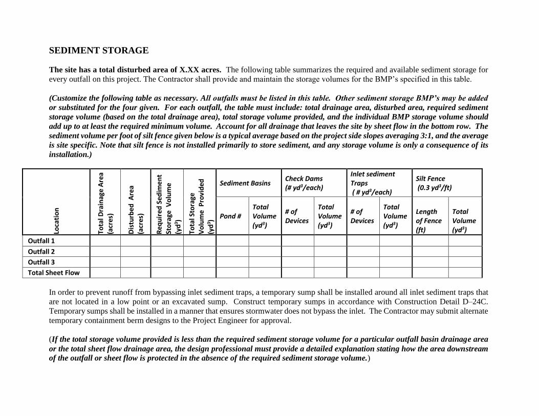
SEDIMENT STORAGE
The site has a total disturbed area of X.XX acres. The following table summarizes the required and available sediment storage for
every outfall on this project. The Contractor shall provide and maintain the storage volumes for the BMP’s specified in this table.
(Customize the following table as necessary. All outfalls must be listed in this table. Other sediment storage BMP’s may be added
or substituted for the four given. For each outfall, the table must include: total drainage area, disturbed area, required sediment
storage volume (based on the total drainage area), total storage volume provided, and the individual BMP storage volume should
add up to at least the required minimum volume. Account for all drainage that leaves the site by sheet flow in the bottom row. The
sediment volume per foot of silt fence given below is a typical average based on the project side slopes averaging 3:1, and the average
is site specific. Note that silt fence is not installed primarily to store sediment, and any storage volume is only a consequence of its
installation.)
Loca
tio
n
Tota
l Dra
inag
e A
rea
(acr
es)
Dis
turb
ed
Are
a
(acr
es)
Re
qu
ire
d S
ed
ime
nt
St
ora
ge V
olu
me
(yd
3 )
Tota
l Sto
rage
V
olu
me
Pro
vid
ed
(yd
3 )
Sediment Basins Check Dams (# yd3/each)
Inlet sediment Traps ( # yd3/each)
Silt Fence (0.3 yd3/ft)
Pond # Total Volume (yd3)
# of Devices
Total Volume (yd3)
# of Devices
Total Volume (yd3)
Length of Fence (ft)
Total Volume (yd3)
Outfall 1
Outfall 2
Outfall 3
Total Sheet Flow
In order to prevent runoff from bypassing inlet sediment traps, a temporary sump shall be installed around all inlet sediment traps that
are not located in a low point or an excavated sump. Construct temporary sumps in accordance with Construction Detail D–24C.
Temporary sumps shall be installed in a manner that ensures stormwater does not bypass the inlet. The Contractor may submit alternate
temporary containment berm designs to the Project Engineer for approval.
(If the total storage volume provided is less than the required sediment storage volume for a particular outfall basin drainage area
or the total sheet flow drainage area, the design professional must provide a detailed explanation stating how the area downstream
of the outfall or sheet flow is protected in the absence of the required sediment storage volume.)

TEMPORARY SEDIMENT BASIN DETAILS:
The table below is provided to show the overall dimensions and significant elevations of each sediment basin. Drainage areas, required sediment storage volumes, and actual sediment basin volumes as measured at the riser crest elevations
are shown in the sediment storage section. See Construction Detail D-22 and Section 54 of the ESPCP plan sheets for further details.
Sed
imen
t B
asin
Inlet
Location
(Station
and
Offset)
Bottom
Elevation
MSL (ft)
Top of
Dam
Elevation
MSL and
Width (ft)
Principal
Spillway
Riser Crest
Elevation
MSL (ft)
Basin
Depth
and
Riser
Height
(ft)
Bottom
Width
(ft)
Bottom
Length
(ft)
Width
at
Riser
Crest
(ft)
Length at
Riser
Crest (ft)
Effective
Length at
Riser
Crest
(ft)
Clean Out
Elevation
MSL (ft)
Emergency
Spillway
Crest
Elevation
MSL (ft)
Emergency
Spillway
Bottom
Width
(ft)
Q2, Q25
(cfs)
Outlet
Pipe
Nominal
Diameter
(inches)
Inside
Width at
Top of
Dam (ft)
Inside
Length
at Top of
Dam (ft)
Overall
Footprint
Width
(ft)
Overall
Footprint
Length
(ft)
Skimmer
Pipe
Nominal
Diameter
(inches)
Skimmer
Orifice
Diameter
(inches)
Drainage
Time
(hr)
1 20+00,
200 ft L 760.00 768.15, 8 765 5 25 50 50 75 100 762.25 766 8 7.6,12.5 24 65 105 93 133 6 4 36
2
3
4
5
6
(The italicized information in the table above is for example only and is to be deleted and replaced with site-specific information. The table may be modified to include detention ponds retrofitted to be used as sediment basins. Note
that if baffles are required to achieve the minimum 2:1 length to width ratio, the effective length, Le, is the flow path length from the inlet to the principal spillway at the riser crest elevation, and Le is equal to or greater than the straight-
line length, L.)
USE OF ALTERNATIVE AND/OR ADDITIONAL BMPS:
(A conventional BMP is one that is shown in the GSWCC “Greenbook”. An alternative BMP is
one that does not appear in the Greenbook with the conventional BMPs and must be specifically
approved on a project-specific basis. A fabric check dam is an example of an alternative BMP.
The GSWCC has a guidance form describing the rigorous approval process for alternative
process. Any BMP other than a conventional BMP or an alternative BMP is an additional BMP.
Only sediment storage provided by conventional or alternative BMPs may be included in the
sediment storage table. Additional BMPs, however, may be used for purposes other than for
sediment storage. A stone filter ring is an example of a conventional BMP and functions similarly
to a silt gate at pipe inlets and outlets. A filter ring used in conjunction with a silt gate (now also
a conventional BMP when used by itself) may also be specified. A retrofit, another conventional
BMP, is used at existing detention/retention pond outlets to convert the pond into a temporary
sediment basin.
Use one of the following statements as a guide or write a statement from scratch that is more
applicable to your project.)
No alternative or additional BMPs will be used on this project.
(If additional BMPs are proposed on the project, use a statement similar to what is below.)
Additional BMPs will be used on this project. . . . will be used on this project as additional BMPs
for . . . and are not being used in place of or as a substitute for other conventional BMPs. The stability
of the site is maintained with the other conventional BMPs as shown on the plans. This ESPCP
would be fully compliant with the GAR100002 permit requirements if the additional BMPs were
removed. Any sediment stored by the additional BMPs is not included in the required minimum
sediment storage volume or shown in the sediment storage table.
(If alternative BMPs are proposed on the project, use a statement similar to what is below. At the time of this update, fabric check dams are the only approved alternative BMP GDOT uses.)
Fabric check dams will be used on this project as an alternative BMP. The use of the alternative
BMP for stone check dams has been reviewed by the Georgia EPD and has been determined by the
Georgia EPD to be allowable only for this ESPCP. This review was site specific and was based on
the documentation submitted and certified by the Level-II Certified Design Professional and was
required by the Georgia EPD and the Georgia SWCC.
DISCHARGES INTO OR WITHIN ONE LINEAR MILE UPSTREAM OF
AND WITHIN THE SAME WATERSHED AS, ANY PORTION OF A BIOTA
IMPAIRED STREAM SEGMENT
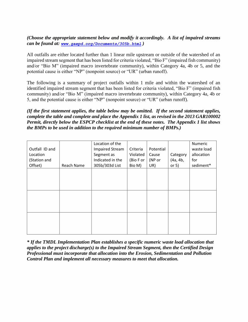
(Choose the appropriate statement below and modify it accordingly. A list of impaired streams
can be found at: www.gaepd.org/Documents/305b.html )
All outfalls are either located further than 1 linear mile upstream or outside of the watershed of an
impaired stream segment that has been listed for criteria violated, “Bio F” (impaired fish community)
and/or “Bio M” (impaired macro invertebrate community), within Category 4a, 4b or 5, and the
potential cause is either “NP” (nonpoint source) or “UR” (urban runoff).
The following is a summary of project outfalls within 1 mile and within the watershed of an
identified impaired stream segment that has been listed for criteria violated, “Bio F” (impaired fish
community) and/or “Bio M” (impaired macro invertebrate community), within Category 4a, 4b or
5, and the potential cause is either “NP” (nonpoint source) or “UR” (urban runoff).
(If the first statement applies, the table below may be omitted. If the second statement applies,
complete the table and complete and place the Appendix 1 list, as revised in the 2013 GAR100002
Permit, directly below the ESPCP checklist at the end of these notes. The Appendix 1 list shows
the BMPs to be used in addition to the required minimum number of BMPs.)
Outfall ID and Location (Station and Offset) Reach Name
Location of the Impaired Stream Segment as Indicated in the 305b/303d List
Criteria Violated (Bio F or Bio M)
Potential Cause (NP or UR)
Category (4a, 4b, or 5)
Numeric waste load allocation for sediment*
* If the TMDL Implementation Plan establishes a specific numeric waste load allocation that
applies to the project discharge(s) to the Impaired Stream Segment, then the Certified Design
Professional must incorporate that allocation into the Erosion, Sedimentation and Pollution
Control Plan and implement all necessary measures to meet that allocation.
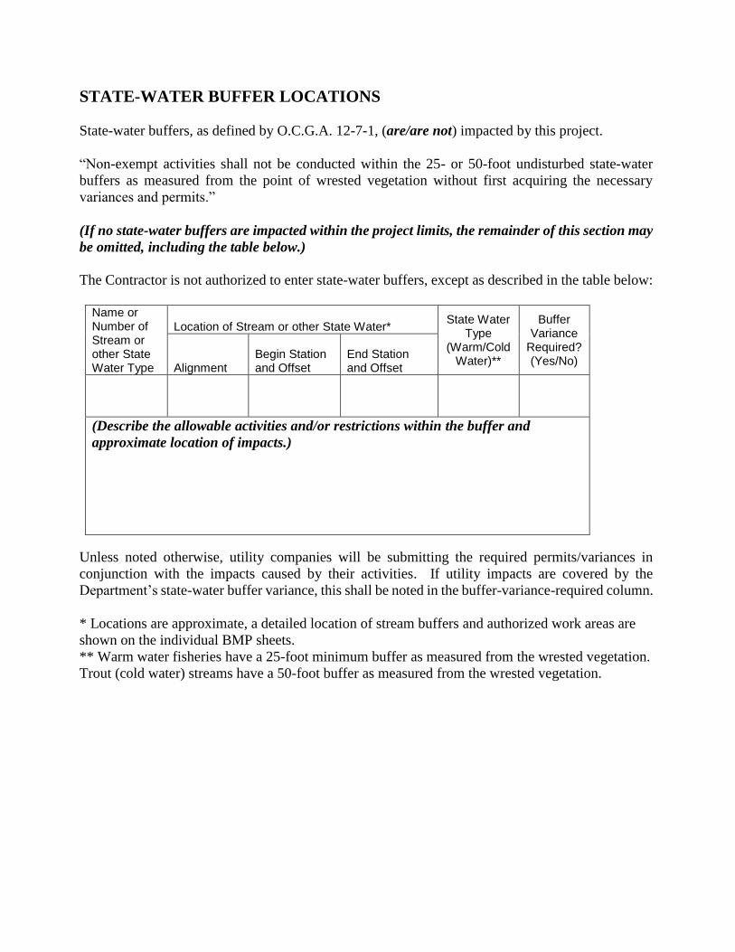
STATE-WATER BUFFER LOCATIONS
State-water buffers, as defined by O.C.G.A. 12-7-1, (are/are not) impacted by this project.
“Non-exempt activities shall not be conducted within the 25- or 50-foot undisturbed state-water
buffers as measured from the point of wrested vegetation without first acquiring the necessary
variances and permits.”
(If no state-water buffers are impacted within the project limits, the remainder of this section may
be omitted, including the table below.)
The Contractor is not authorized to enter state-water buffers, except as described in the table below:
Name or Number of Stream or other State Water Type
Location of Stream or other State Water* State Water
Type (Warm/Cold
Water)**
Buffer Variance
Required? (Yes/No)
Alignment Begin Station and Offset
End Station and Offset
(Describe the allowable activities and/or restrictions within the buffer and
approximate location of impacts.)
Unless noted otherwise, utility companies will be submitting the required permits/variances in
conjunction with the impacts caused by their activities. If utility impacts are covered by the
Department’s state-water buffer variance, this shall be noted in the buffer-variance-required column.
* Locations are approximate, a detailed location of stream buffers and authorized work areas are
shown on the individual BMP sheets.
** Warm water fisheries have a 25-foot minimum buffer as measured from the wrested vegetation.
Trout (cold water) streams have a 50-foot buffer as measured from the wrested vegetation.

SAMPLING GENERAL NOTES:
Representative sampling may be utilized on this project as explained here. The individual outfall drainage basins along the project corridor have been carefully evaluated and compared on the basis of four characteristics: the
type of construction activity, the disturbed acreage, the average slope about the outfall, and the soil erosion index 0-10, 10 being the most erodible soil. The construction activity types are new road on fill, new road in cut, road
widening, and maintenance/safety. The disturbed area classes are less than or equal to 1 acre, greater than 1 acre to less than 2 acres, and equal to or greater than 2 acres. The average outfall slope is mild if it is equal to or less
than 0.03, and steep if it is greater than 0.03. The soil erosion index is low if it is less than or equal to 5 and high if it is greater than 5. After evaluation of these characteristics as presented in the project’s drainage area map,
hydrology and hydraulic studies, construction plans, geotechnical soil survey, and erosion sedimentation and pollution control plans, the Department has determined that the representative sampling scheme shown below is
valid for the duration of the project. The table shows the groups of similar outfall drainage basins.
The increase in turbidity at the specified locations in the table below will be representative of the alternate outfall drainage basins when similar outfall drainage basins exist. Approved primary and alternate representative
sampled features are identified in the table below.
Note: The total site area is X.XX acres. Representative Sampling Scheme
SAMPLING INFORMATION OUTFALL CHARACTERISTICS
Pri
mar
y S
amp
led
Fea
ture
Location
(station
and
offset)
Name of
Receiving
Water
Applicable
Construction
Stage for
Sampling
Sampling
Type
(outfall or
receiving
water)
Drainage
Area
for the
receiving
water
(mi2)
Warm
or Cold
Water
Stream
Appendix B
NTU Value
(outfall
sampling only)
Allowable
NTU
Increase
(receiving-
water
sampling
only)
Location
Description
Construction
Activity
Disturbed
Area (acres)
Average
Outfall Slope
(rise/run)
Soil Erosion
Index
Represented
Outfall
Drainage
Basins
1 Up
20+00,
200 ft L
Sunset
Creek All
Receiving
Water 5.0 Warm N/A 25 Upstream
Road
Widening N/A N/A N/A N/A
1 Dn
20+50,
150 ft R
Sunset
Creek All
Receiving
Water 7.2 Warm N/A 25 Downstream
Road
Widening N/A N/A N/A N/A
1
15+41,
130 ft R
Sunset
Creek All Outfall 6.0 Warm 50 N/A End of Ditch
Road
Widening 4.1 0.10 2 5
2
20+61,
130 ft L
Sunset
Creek All Outfall 5.2 Warm 50 N/A End of Ditch
Road
Widening 3.4 0.02 3 N/A
3
22+60,
120 ft R
Sunset
Creek All Outfall 5.4 Warm 50 N/A End of Ditch
New Road--
Cut 2.1 0.02 5 N/A
6
23+41,
130 ft L
Sunset
Creek All Outfall 5.7 Warm 50 N/A End of Ditch
New Road--
Fill 3.5 0.03 3 9
8
25+51,
130 ft R
Sunset
Creek All Outfall 6.0 Warm 50 N/A End of Ditch
New Road--
Fill 5.0 0.10 2 4,7,11,12
10
31+80,
120 ft R
Sunset
Creek All Outfall 6.2 Warm 50 N/A End of Ditch
New Road--
Fill 3.1 0.03 7 N/A
(Note that outfall sampling requires one sample per event while receiving-water sampling requires a pair of samples, one sample upstream and one sample downstream, per event for comparison. The italicized example
information in the table represents the minimum number of sampled features for representative sampling and is to be replaced with site-specific information. Alternate sampled features are optional. According to the
EPD, additional sampling sites may be required depending on significant changes during the project. Determine the representative sampling scheme by using the Representative Sampling Database for GDOT internal
use on the R.O.A.D.S. webpage under Design Policies and Guidelines in the ESPCP box Internal Representative Sampling Database. For consultants, use the external database External Representative Sampling Database.
Alternatively, determine the scheme by hand.)
The primary sampled features specified should be used as the initial sampling locations. An alternate sampled feature may be used if additional sampling is required or to replace a primary sampled feature that is no longer
located within the active phase of construction.

WATER QUALITY INSPECTING AND SAMPLING PROCEDURES
See Special Provision 167 and other contract documents for the inspecting and sampling procedures.
READY MIX CHUTE WASH DOWN
The washing of ready-mix concrete drums and dump truck bodies used in the delivery of Portland
cement concrete is prohibited on this site.
In accordance with Standard Specification 107: Legal Regulations and Responsibility to the Public,
only the discharge chute utilized in the delivery of Portland cement concrete may be rinsed free of
fresh concrete remains. The Contractor shall excavate a pit outside of State water buffers, at least 25
feet from any storm drain and outside of the travelled way, including shoulders, for a wash-down
pit. The pit shall be large enough to store all wash-down water without overtopping. Immediately
after the wash-down operations are completed and after the wash-down water has soaked into the
ground, the pit shall be filled in, and the ground above it shall be graded to match the elevation of the
surrounding areas. Alternate wash-down plans must be approved by the Project Engineer.
Wash-down plans describe procedures that prevent wash-down water from entering streams and
rivers. Never dispose of wash-down water down a storm drain. Establish a wash-down pit that
includes the following: (1) a location away from any storm drain, stream, or river, (2) access to the
vehicle being used for wash down, (3) sufficient volume for wash-down water, and (4) permission to
use the area for wash down.
On sites where permission or access to excavate a wash-down pit is unavailable, the Contractor may
have to wash-down into a sealable 55-gallon drum or other suitable container and then transport the
container to a proper disposal site. For additional information, refer to the Georgia Small Business
Environmental Assistance Program's "A Guide for Ready Mix Chute/Hopper Wash-down".
EROSION, SEDIMENTATION, and POLLUTION CONTROL CHECKLIST:
(Include the completed applicable ESPCP checklist as the next drawing numbered sheet. Ensure
that the checklist is dated January 1 for the current year.)
APPENDIX 1 to the EROSION, SEDIMENTATION, and POLLUTION
CONTROL CHECKLIST:
(If applicable to your project by Part III C. of the current GAR100002 Permit, choose at least four
(4) additional BMPs, show them on the Appendix 1 BMP list referenced by item 17 of the ESPCP
checklist, and include Appendix 1 as the drawing number of these ESPCP General Notes. If not
applicable, delete this section from the plans.)