eServer BladeCenter Remote SAN Boot for JS20 - …qgt.qlogic.com/Hidden/support/Current Answer...
58
Page 1 of 58 Dense computing and redundant storage consolidation September 2004 IBM eServer TM BladeCenter Remote SAN Boot for JS20 Mats Wahlstrom BladeCenter SME IBM Integrated Technology Services Greenock, UK Mark Wenning Development Engineer IBM Systems & Technology Group Austin, TX Cedric Cook Development Engineer IBM Systems & Technology Group RTP, NC
Transcript of eServer BladeCenter Remote SAN Boot for JS20 - …qgt.qlogic.com/Hidden/support/Current Answer...

Page 1 of 58
Dense computing and redundant storage consolidation September 2004
IBM eServerTM BladeCenter Remote SAN Boot for JS20
Mats Wahlstrom BladeCenter SME
IBM Integrated Technology Services Greenock, UK
Mark Wenning Development Engineer
IBM Systems & Technology Group Austin, TX
Cedric Cook Development Engineer
IBM Systems & Technology Group RTP, NC

Page 2 of 58
Acknowledgements Thanks to the many who have contributed to the finalization of this document. Without your expertise and critiques, this document wouldn’t have come together. Many Thanks!

Page 3 of 58
Table of Contents 1. 0 Overview............................................................................................................................. 4 2. 0 Change Notification ............................................................................................................ 5 3. 0 Using this document ........................................................................................................... 6 4. 0 Preparation Checklist ......................................................................................................... 7 5. 0 About the BladeCenter I/O Subsystem .............................................................................. 8 6. 0 Preparing the BladeCenter Server FC Expansion card for Remote Boot .......................... 9
6.1 Installing the FC Expansion Card .............................................................................. 9 6.2 Record Host Adapter Port Name............................................................................. 10 6.3 Configuring FC Expansion card parameters ........................................................... 11
7.0 Configuring IBM eServer BladeCenter FC Modules......................................................... 11 7.1 Configuring Fibre Channel Switch module for a Remote Boot environment ........... 11 7.2 Configuring Optical Pass-thru module for a Remote Boot environment.................. 13 7.3 Configuring a Single Path to the Storage Server..................................................... 14
8.0 Configuring Fibre Channel Storage arrays....................................................................... 15 8.1 Configuring DS4000 series Storage for Remote boot ............................................. 15 8.2 Configuring ESS Storage for Remote boot.............................................................. 17
9.0 Configuring Boot Sequence for Installing from CD........................................................... 19 10.0 Configuring Serial Over LAN (SOL) ................................................................................. 19 11.0 Verifying path to FC device .............................................................................................. 22 12.0 Installing the AIX Operating System................................................................................. 24
12.1 Installing AIX 5.2H or later ....................................................................................... 24 13.0 Installing the Linux Operating System.............................................................................. 29
13.1 Installing SLES8 SP3A or later ................................................................................ 29 13.2 Installing RHEL3 U3 or later .................................................................................... 37
14.0 Configuring Boot Sequence and Open Firmware for Remote Boot ................................. 46 15.0 Configuring for Redundancy............................................................................................. 48
15.1 Enable second switch path ...................................................................................... 49 15.2 DS4000 series ......................................................................................................... 49 15.3 ESS.......................................................................................................................... 52
16.0 Installing Service Aids and Updating the Open Firmware on JS20.................................. 53 Appendix A: Single/Dual-path Concept Diagrams................................................................... 55 Appendix B: BladeCenter SAN Options Equipment List.......................................................... 56
Summary................................................................................................................................. 57 Additional Information ............................................................................................................. 57

Page 4 of 58
1.0 Overview Remote boot or “root boot” is the name used when referring to a server configuration where the
Server’s operating system is installed on a logical drive (LUN) that is not resident locally to the Server chassis. This document will describe in details the process that you must go through to setup a remote boot for IBM eServer BladeCenter Servers using a logical drive from Fibre Channel Storage Array.
This process is intended for a configuration of a Blade Center directly connected to the Storage
Array using Fibre Channel (FC) cables (Figure 1) If the Blade Server is connected to the Storage Array via FC switches (Figure 2), please reference the IBM eServer BladeCenter Interoperability guide first for instructions to correctly integrate the BladeCenter into an existing FC switched fabric. Upon following these preliminary tasks, you will be able to use the information in this document to set up remote boot.
Figure 1.- BladeCenter in Direct-attach SAN environment
Figure 2.- BladeCenter in Fabric-attach SAN environment

Page 5 of 58
2.0 Change Notification
Change Revision Description Date 1.0 Initial release TBD

Page 6 of 58
3.0 Using this document This document will demonstrate to the Storage Administrator audience how to prepare, configure,
and boot the IBM eServer BladeCenter using IBM Fibre Channel based storage solutions. The initial view of this document describes how to configure the Blade Center Fibre Channel expansion adapter, provides a brief overview of the BladeCenter I/O module subsystem, and detailed steps for configuring Remote boot. Additionally, this document describes ‘how to’ and best practices for configuring the Fibre Channel capable modules using DS4000 disk systems series (formerly FAStT) and ESS Storage platforms. I would like to point out that this document was not intended for use in configuring Clustered Hosts for Remote boot.

Page 7 of 58
4.0 Preparation Checklist As a preparation procedure, ensure that you either have access or have researched the following areas before proceeding to configuration. Fibre Channel expansion adapter
Verify that the FC Expansion card option is p/n: 73P6112, which supports JS20 remote boot. Options 13N2203 and 48P7061 are supported in the JS20. However, they are not boot capable.
Review the Blade Center Fibre Channel Adapter Installation & User’s guide. Refer to the Storage vendor’s Settings for assigning the Boot LUN. In most cases, this will be LUN 0
(zero). Ensure that the Fibre Channel Adapter has the latest supported F-Code, known as FC BIOS in the Intel
space. This is located at: www.ibm.com/support. Fibre Channel Switch Module
Review the appropriate Switch Module installation & User’s guide. For the Optical Pass-thru module, ensure that the OPM (break-out) cable is using the correct mapping
to identify the Blade that you intend to configure for remote booting, this is further explained in section 7.2.
Review the Blade Center’s Fibre Channel switch Interoperability Guide. Backup the switch fabric configuration to a file. Record the IP Addresses of the BladeCenter Fibre Channel Switch module.
Remote Management workstation for configuring remotely
Configure a Remote Management workstation which can be used to access the Fibre Channel switch module via an IP address. This is a system with the IBM FAStT Storage Manager installed also and can be used to manage the storage.
If using the Embedded IBM BladeCenter 2-port Fibre Channel Switch Module or IBM BladeCenter 6-port Fibre Channel Switch Module, install the IBM SAN Browser (previously called Utility) switch management application on the Remote Management workstation to have a graphical interface for managing the Fibre Channel Switch module. This workstation should be running the latest Java Utility.
DS4000 disk systems series (formerly FAStT) Storage
Reference the most current DS4000 series readme files, Installation and User’s guides to ensure that you are comfortable with the configuration to follow. Otherwise, contact your local Blade Center support representative.
Install the Storage Manager software on the Remote Management workstation for storage management.
Obtain the IP Addresses of the DS4000 series Storage subsystem. Obtain the necessary Storage Partitioning Premium Feature if required. Ensure that the DS4000 series Storage subsystem and drives are cabled in accordance with the DS4000
series cabling guide.

Page 8 of 58
ESS Storage Reference the most current ESS Readme, Installation and User’s guides to ensure that you are
comfortable with the configuration to follow. Otherwise, contact your local Blade Center or Storage support representative.
5.0 About the BladeCenter I/O Subsystem The IBM eServer BladeCenter is capable of containing up to fourteen processor blades for the Enterprise chassis and eight for the Telco chassis, two management modules, and four total I/O modules. Based on the current blade design, only Ethernet1 (ENET) or Optical Pass-thru (OPM) I/O modules can be inserted into Bays 1 & 2. Any type of defined switch module, for example the Ethernet Switch Modules, Fibre Channel and Optical-Pass-Thru, can be inserted into Bays 3 & 4. However, for the purpose of this document, the I/O module will either be a Fibre Channel switch or Optical Pass-Thru module used in Slots 3 or 4. The corresponding blade server I/O expansion card must match with the I/O module protocol type. For example, the Fibre Channel daughter-card supports the Fibre protocol and only the OPM or Fibre Channel switch module is supported. On a BladeCenter chassis, the four switch bays are numbered from a rear view perspective as shown in below in Figure 3. Also, the JS20 blade server requires two Ethernet switches to be installed, in Bays 1 & 2. Bay 1 requires a Serial Over LAN (SOL) capable Ethernet switch module and Bay 2 requires a Ethernet switch module for data traffic. For additional information about SOL requirements, see the “Enabling and configuring SOL (Serial Over LAN) on an 8842 Blade Server Whitepaper” for more in-depth SOL instructions, this can be found at: http://www-3.ibm.com/pc/support/site.wss/document.do?lndocid=MIGR-55018
Figure 3. Enterprise and Telco Blade Chassis Rear view (I/O subsystem)
1
Ethernet will be abbreviated as ENET in the rest of this document.

Page 9 of 58
6.0 Preparing the BladeCenter Server FC Expansion card for Remote Boot
This section is intended to provide a description and steps for preparing the JS20 Blade Servers with and I/O expansion card in preparation to Remote Boot from Fibre Channel Storage. The JS20 Server Blade has the capabilities of using the FC Expansion card that is designed with dual-channels. When the Blades using FC expansion cards are inserted into the BladeCenter’s chassis they interface with two mid-plane’s which provides connectivity to I/O modules 3 and 4 in the rear of the chassis. The diagram in Figure 4 depicts placement of the FC expansion card on the Server blade. For a more detailed overview of the FC expansion card, you should refer to the Installation and User’s guides.
Figure 4. -JS20 Blade FC Expansion card layout
6.1 Installing the FC Expansion Card NOTE: The IBM BladeCenter JS20 Fibre Channel Expansion Card - option part number (p/n) 73P6112 is currently the only adapter which has been tested for remote boot with JS20.
1. Ensure that the JS20 blade server is powered-off. 2. Remove the JS20 blade server from the chassis (if installed in the chassis).
3. Remove the cover of the JS20 blade server.
4. Remove the FC Expansion Card from the static-protective package.
5. Slide the narrow end of the FC Expansion Card into the raised hook on the tray.

Page 10 of 58
6. Align the FC Expansion Card connectors with the network-interface option connector and the PCI-X expansion slot.
7. Gently press the card into the connectors.
8. Lower the cover so that the slots at the rear slide down onto the pins at the rear of the blade server. Important: The blade server cannot be inserted into the BladeCenter unit until the cover is installed and closed. Do not attempt to override this protection. The following example (Figure 5) shows how to install an FC expansion card on the blade server.
Figure 5. –JS20 Blade FC Expansion card layout
9. Install the JS20 blade server into the BladeCenter chassis.
6.2 Record Host Adapter Port Name
Gather the WWN of the host adapter in the blade from the name server of the fibre switch module, as shown in the following example. This information is needed later to map the LUNs to the JS20 blade server using Storage Partitioning (LUN masking). NOTE: This should be gathered from both paths. Brocade Switch Module Commands Qlogic Switch Module Commands 1. Start a telnet session and login to the switch 2. BSSM: >nsShow 3. BSSM: > logout
1. Start a telnet session and login to the switch
2. FCSM: USERID> admin start 3. FCSM (admin): USERID> ns show 4. FCSM (admin): USERID> admin end 5. FCSM (admin): USERID> logout
Alternatively, the WWPN can be gathered from the Open Firmware command line, as shown in the following example. Open Firmware command line
1. Power on the JS20 blade server. During the boot, at the D5BB prompt, press <8> to enter the Open Firmware command line.
2. Type " /pci@8000000f8000000/pci@1f/fibre-channel@1" select-dev
<== move to fibre-channel node

Page 11 of 58
select-dev QLogic QLA2312 Fibre Channel Host Adapter fcode version 1.03 08/03/04 Firmware version 3.03.01 ok
3. 0 > my-wwn ok 4. 1 >. 2100000d60d31448 ok
<== type my-wwn <== type . to print it
6.3 Configuring FC Expansion card parameters The default settings should be used for the FC expansion adapter.
7.0 Configuring IBM eServer BladeCenter FC Modules
This section describes I/O modules that support the FC expansion card. Therefore, I/O modules must reside in slots 3 or 4. The I/O modules are provided in two flavors; Fibre Channel Switches and Optical Pass-thru modules that can be used as interconnects to attach the Blade Center into an external SAN environment.
The Fibre Channel switch module is designed to reduce the amount of cabling that is used to
interface to the external SAN environment. The Fibre Channel switch module also has resident functionality of a traditional Fibre Channel switch.
The Optical Pass-thru module is designed to allow I/O expansion card break-out capabilities to an
external SAN environment. Because the optical break-out provides a one-to-one (FC expansion-to-external device) port correlation, it may become more feasible to utilize an intermediate switch device. This intermediate switch device allows cable extensibility and aggregates the flow of traffic to a Target device with minimal port-count. NOTE: The instructions in this section assumes that the FC modules has been installed and configured with an IP-address. You should consult the documentation that comes with the FC module for additional guidance.
7.1 Configuring Fibre Channel Switch module for a Remote Boot environment
This section describes two important concepts; Zoning and Interoperability. These should be considered when deploying BladeCenter in a Remote boot SAN environment while using Fibre Channel Switch Modules. Also, this section does not assume that you are using a particular type of Fibre Channel switch module, only that the switch module inside the BladeCenter is a functional IBM eServer BladeCenter Fibre Channel switch module. The following embedded BladeCenter FC modules have been tested for remote boot with the JS20 blade server:
Type IBM BladeCenter 2-port Fibre Channel Switch Module IBM BladeCenter 6-port Fibre Channel Switch Module Brocade Entry SAN Switch Module for IBM BladeCenter IBM eServer BladeCenter Optical Passthru Module (OPM)
A. Zoning

Page 12 of 58
Zoning is used to prevent propagation of state-change traffic to other Blades in the Fabric. It is recommended that each Blade that has I/O expansion cards resident be included in a separate zone. This is to prevent extraneous State-change traffic to other Blades that may be in operation. Although in most cases, this traffic is non-disruptive, it can have a slight performance impact on adjacent Blades in the fabric.
Figure 17. - Zoning Concept
Follow the zoning example provided in Figure 18 to guide you through zoning setup for your configuration. IBM eServer Brocade SAN Switch Module (using CLI)
IBM eServer Fibre Channel 2-port FC Switch Module (using CLI)
1. brocadessm:USERID> zonecreate “Blade1”,”Domain,Port”
2. brocadessm:USERID> zonecreate “Blade1”,”WWPn”
3. brocadessm:USERID> cfgcreate “RemoteBoot”, “Blade1”
4. brocadessm:USERID> cfgenable “RemoteBoot” 5. brocadessm:USERID> cfgsave
1. Start a zone editing session: cli $> admin start cli (admin) #> zoning edit
2. Create a zoneset: cli (admin-zoning) #> zoneset create RemoteBoot
3. Create a zone: cli (admin-zoning) #> zone create Blade1 cli (admin-zoning) #> zone add Blade1 Domain1, Port1 cli (admin-zoning) #> zone add Blade1 WWPn
4. Make the zone a member of the zoneset: cli (admin-zoning) #> zoneset add RemoteBoot Blade1
5. Save the zoning session: cli (admin-zoning) #> zoning save
6. Activate the zoneset: cli (admin) #> zoneset activate RemoteBoot
7. Exit from admin mode: cli (admin) #> admin end

Page 13 of 58
Figure 18. - Zone Configuration steps using the Brocade SAN switch Module and 2-port FC switch Module NOTE: These zoning steps must be repeated for each Fibre Channel Switch Module.
B. Interoperability For SAN environments that operate on the premise of Open Fabrics, interoperability may be
inherent. Open Fabrics are SANs where vendor neutral device integration is permissible. Interoperability is described as interconnecting two or more Switch Fabric devices of different vendor types.
When attaching the BladeCenter into any SAN environment, it is important to understand the SAN
vendor of the devices that you are attaching to. Once this is determined, you should proceed to gathering appropriate documentation that will guide you in designing this interoperable SAN. For the purpose of Remote booting, you should consult the Storage vendor to ensure that Interoperable Fabrics are supported. For best practices, before proceeding to integrate the BladeCenter into an existing Fabric, you should backup your switch configuration. Additionally, for BladeCenter Interoperability guidelines see the IBM eServer BladeCenter Fibre Channel Interoperability Guide, available at http://www.pc.ibm.com/support.
7.2 Configuring Optical Pass-thru module for a Remote Boot environment NOTE: Red Hat LINUX Version 3 Update 2 does not support OPM. See Retain tips H182518 for more information.
The Optical Pass-thru module (OPM) provides 4-pair of fiber optic cable break-outs per single Optical transceiver. The OPM has 4 Optical transceivers numbered 1 thru 4 on the face of the OPM that allows communication to the device. Each cable correlates to a particular Blade slot. For example, break-out Cable extension 1 thru 4 of Optical transceiver port 1 correlates with the Blades in slot 1 thru 4. The break-out cable extension 1 thru 4 of Optical transceiver port 2 correlates with Blades in slot 5 thru 8 and so on. Depending on whether the OPM is in slot 3 or 4 will determine whether you have connectivity to the upper or lower port of the I/O Expansion card.
Figure 19. - Optical Pass-Thru Module and Break-out (SC-type) cable

Page 14 of 58
Because the OPM serves as a physical extension of the FC expansion card ports, there is not a concern for Interoperability or zoning on the OPM per se. The SAN Administrator should be mindful of cable management and port-count when designing a SAN using OPM.
Figure 20. - SAN diagram using OPM
As shown in figure 20, the OPM is directly attached to the external switch. The external switch can be zoned as described in the zoning section of “Configuring Fibre Channel Switch module for Remote boot environment” section of this document. It is also recommended to consult the switch vendor’s documentation to find out more about Zoning.
7.3 Configuring a Single Path to the Storage Server During the installation of you Operating System there should only be one path active to each JS20 blade server. The second or alternate paths can be activated after the installation of the Operating System. Follow the steps in the following example to disable the second path on your embedded BladeCenter switch. If you are using a OPM, simply remove the FC cable going to the OPM in slot 4 during the installation of the OS. Note: In this example, the Storage Subsystem is connected to port 0 on the embedded BladeCenter switch module. Brocade Switch Module Commands Qlogic Switch Module Commands 1. Start a telnet session to the switch 2. Login using ‘USERID’ 3. BSSM: > portDisable 0 4. BSSM: > logout
1. Start a telnet session to the switch 2. FCSM: USERID> admin start 3. FCSM (admin): USERID> config edit 4. FSCM (admin-config): USERID> set config port
0 5. set port 0 to offline 6. FSCM (admin-config): USERID> config save 7. FCSM (admin): USERID> config activate 8. FCSM (admin): USERID> admin end 9. FCSM (admin): USERID> logout

Page 15 of 58
8.0 Configuring Fibre Channel Storage arrays Up to this point, the Storage Administrator has configured the Blade Server, FC Expansion card,
and FC module. During the installation of the Operating System it is highly recommended that there is only one single path enabled to the blade, as multiple paths can cause problems during the installation. Once the Operating System has been installed, you can enable the second/alternate path and continue to configure the blade for multi pathing. This section describes attaching the IBM eServer BladeCenter into a SAN and configuring the Blade to Remote boot devices from the DS4000 series or ESS storage array. NOTE: The instructions in this section assumes that the Storage subsystem has been installed and configured with an IP-address. You should consult the documentation that comes with the Storage Subsystem for additional guidance. Also, note that IBM ESS and DS4000 series has only been tested for remote boot with the JS20 blade server.
8.1 Configuring DS4000 series Storage for Remote boot
NOTE: The following steps will be performed from a Remote workstation that has the FAStT Total Storage Manager client installed. You should consult the DS4000 series documentation for additional guidance. 1. Install the IBM FAStT Storage Manager Client on the designated Remote workstation.
2. Launch the IBM FAStT Storage Manager Client, for in-depth instructions consult the DS4000
series documentation.
3. Using the Storage Management application, connect to the Storage subsystem that you intend to manage and configure for Remote booting.
4. Once you have selected the Storage subsystem that you want to configure for remote boot, proceed
to Creating logical drives and arrays. To do this, right click on <unconfigured capacity> and select <Create Logical drive>, as shown in the figure 7 below. Follow the wizard to create a logical drive to suit your requirement. For further information see the DS4000 series documentation. NOTE on Adding Volumes: You will want to add 2-3 GB LUN, for Operating Systems Purposes. Additional volumes can be added after the installation of the OS. Perform the Configuration Update. Only one volume should be assigned to the Host until the installation of the Operating System has been completed.

Page 16 of 58
Figure 7. - Storage Manager client management screen.
5. Proceed to configure Storage partitioning by performing the steps below. NOTE: You should review your DS4000 series publications, these will provide more in-depth examples on Storage Partitioning.
6. Under the Mappings View tab, you should create a host group, host, and assign host ports. a. Select <Mappings> <Define Host Group>. b. Click on the Host group; select <Mappings> <Define> <Host>. c. Click on the Host that was created in the previous step; select Mappings Define
Host-ports. Each Host should initially have a single host-port assigned. Otherwise, the host will have dual-path access assigned. The host port is the Adapter WWPN that you recorded while configuring the FC Expansion card. The host type for each of these host-port types will be Windows® Non-clustered by default and should be changed to correspond to the Operating system type that you will be installing.
Figure 8. -Configuring Host groups and defining Host ports
7. Right click on the host created in Step 6 and assign the intended boot Logical Drive, as LUN 0, to the Host that was also created previously.

Page 17 of 58
8. Remove the Access Logical Drive from the Host group created in Step 6. NOTE: This LUN is added automatically to the host group when the first LUN is mapped to it. Review the figure below to compare with your configuration.
Figure 9. - DS4000 series Host-port mapping
8.2 Configuring ESS Storage for Remote boot
NOTE: The following steps will be performed from a Remote workstation that has been configured to use the ESS Specialist. You should consult the ESS documentation for additional guidance. 1. Configure the ESS using the ESS Specialist.
-Storage Allocation -Open Systems -Modify Host Systems.
2. Enter the information in the text fields of the Modify Host System, as shown in the following example.

Page 18 of 58
3. Add the Host Attributes to the Host Systems List and Perform Configuration Update.
4. After the Configuration Update you will be brought to the Open Systems Storage Window, Add Volumes to the Host. Select the <Add volumes>.
Figure 11. - ESS Host-port mapping
5. Click on your Host (Host Nickname), and select clusters (Green) from Cluster 1 and/or Cluster 2,
then select Next. NOTE on Adding Volumes: You will want to add 2-3 GB LUN, for Operating Systems Purposes. Additional volumes can be added after the installation of the OS. Perform the Configuration Update. Only one volume should be assigned to the Host until the installation of the Operating System has been completed.
Figure 12. - ESS Host-port mapping
6. You will then see the 2-3GB LUN that was created and that it is assigned to the WWPN of the FC
Expansion card.
Page 19 of 58
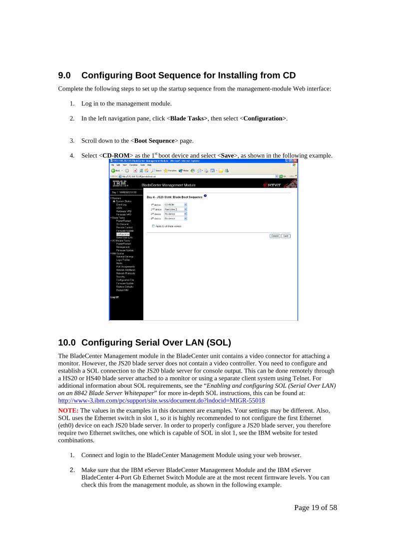
9.0 Configuring Boot Sequence for Installing from CD Complete the following steps to set up the startup sequence from the management-module Web interface:
1. Log in to the management module. 2. In the left navigation pane, click <Blade Tasks>, then select <Configuration>.
3. Scroll down to the <Boot Sequence> page. 4. Select <CD-ROM> as the 1st boot device and select <Save>, as shown in the following example.
10.0 Configuring Serial Over LAN (SOL) The BladeCenter Management module in the BladeCenter unit contains a video connector for attaching a monitor. However, the JS20 blade server does not contain a video controller. You need to configure and establish a SOL connection to the JS20 blade server for console output. This can be done remotely through a HS20 or HS40 blade server attached to a monitor or using a separate client system using Telnet. For additional information about SOL requirements, see the “Enabling and configuring SOL (Serial Over LAN) on an 8842 Blade Server Whitepaper” for more in-depth SOL instructions, this can be found at: http://www-3.ibm.com/pc/support/site.wss/document.do?lndocid=MIGR-55018 NOTE: The values in the examples in this document are examples. Your settings may be different. Also, SOL uses the Ethernet switch in slot 1, so it is highly recommended to not configure the first Ethernet (eth0) device on each JS20 blade server. In order to properly configure a JS20 blade server, you therefore require two Ethernet switches, one which is capable of SOL in slot 1, see the IBM website for tested combinations.
1. Connect and login to the BladeCenter Management Module using your web browser. 2. Make sure that the IBM eServer BladeCenter Management Module and the IBM eServer
BladeCenter 4-Port Gb Ethernet Switch Module are at the most recent firmware levels. You can check this from the management module, as shown in the following example.

Page 20 of 58
NOTE: To update the firmware, see the documentation that comes with the blade server and the readme file that comes with the firmware update package.
3. To enable SOL, on the management module, in the left navigation pane, select <Blade Tasks>, then <Serial Over LAN>, as shown in the following example.
4.
The default management-module SOL settings provide the best overall SOL performance. You can modify these settings to meet requirements that are specific to your BladeCenter unit or network configuration. The default SOL values are:

Page 21 of 58
Serial Over Lan: Enabled Use this field to enable or disable SOL globally for the BladeCenter unit. Enabling or disabling SOL globally does not affect the SOL session status for each blade server.
SOL VLAN ID: 4095 This value is fixed and cannot be modified.
BSMP IP Address Range: x.x.x.x This is a mandatory field where x.x.x.x is the base IP address for blade servers in the BladeCenter unit. The IP address that SOL uses to communicate with the blade system management processor (BSMP) of each blade server is based on the IP address that is set in this field. For example, if the value that you enter is 10.1.1.1, the blade server in blade bay 1 will have IP address 10.1.1.1, the blade server in blade bay 2 will have IP address 10.1.1.2, and so on.
Accumulate timeout: 5 Send threshold: 250 Retry count: 3 Retry interval: 250
5. Select <Save>.
6. Enable SOL for each blade server. (For each blade server, scroll down to the Serial Over LAN Configuration section, and in the Serial over LAN field, select Enabled.), as shown in the following example.
7. Make sure that the status of the SOL session is <Ready> and that SOL is <Enabled>, as shown in the following example.

Page 22 of 58
8. SOL has now been configured.
11.0 Verifying path to FC device This section will verify that the Open Firmware can see the FC disk that you have assigned to the JS20 blade server.
1. Power on the JS20 blade server.
2. Telnet to the management module (MM) and start a SOL session, as shown in the following example. In this example the JS20 blade server is located in slot 4 in the BladeCenter chassis.
1. >telnet 192.168.70.125 2. username: USERID 3. password: ******** 4. system> console -T blade[4]
3. During the boot, at the D5BB prompt, press <8> to enter the Open Firmware prompt. 4. Type <dev/packages/gui> and press enter. Then type <setup-fcp-disk> and press enter to start
the mini SMS, as shown in the following example. D5BB 4 E1A1 E1A8 ok 0 > dev /packages/gui ok 0 > setup-fcp-disk
5. At the “Main Menu”, select <2> and press enter, as shown in the following example.

Page 23 of 58
pSeries Firmware Version FW04251120 SMS 1.3 (c) Copyright IBM Corp. 2000,2004 All rights reserved. ---------------------------------------------------------------- Main Menu 1. Select Language 2. Select Media Adapter ---------------------------------------------------------------- Navigation Keys: X = eXit System Management Services --------------------------------------------------------------- Type the number of the menu item and press Enter or select Navigation Key:2
6. At the “Select Media Adapter” screen, select <1> and press enter, as shown in the following
example. Select Media Adapter 1. U8842.P1Z.23A0626-P1-C5-T1 /pci@8000000f8000000/pci@1f/fibre-chanel@1 ------------------------------------------------------------- Navigation keys: M = return to Main Menu ESC key = return to previous screen X = eXit System Management Services ------------------------------------------------------------- Type the number of the menu item and press Enter or select Navigation Key: 1
7. Verify that you can see the FC Harddisk in the device list, as shown in the following example.
scan /pci@8000000f8000000/pci@1f/fibre-channel@1/disk@QLogic QLA2312 Fibre Channel Host Adapter fcode version 1.03.13 06/22/04 Firmware version 32.27.06 check /pci@8000000f8000000/pci@1f/fibre-channel@1/disk@21000004cf2fcded,00- pSeries Firmware Version FW04271120 SMS 1.3 (c) Copyright IBM Corp. 2000,2004 All rights reserved. ------------------------------------------------------------- Select Device Device Current Device Number Position Name 1. - SCSI 36401 MB FC Harddisk ( loc=U8842.P1Z.23A0626-P1-C5-T1-L21 000004cf2fcded-L00 ) -------------------------------------------------------------Navigation keys: M = return to Main Menu ESC key = return to previous screen X = eXit System Management Services ------------------------------------------------------------- Type the number of the menu item and press Enter or select Navigation Key: 1
8. Type <X> to exit and then <Power Off> the JS20 blade server.

Page 24 of 58
12.0 Installing the AIX Operating System
Now that you have configured the FC Expansion card, FC switches and Storage - you are now ready to begin the installation of the Operating System. The following AIX levels have been validated and are subjects of this section:
Operating System AIX 5.2H
To install AIX on JS20, use one of the following two methods:
• Network Install using Network Installation Manger (NIM) – See the AIX documentation • Installation using CD-ROM
The instructions in this document will describe how-to install AIX on a JS20 blade server using a CD-ROM.
12.1 Installing AIX 5.2H or later
1. Insert the AIX 5.2 CD1 in to the CD-ROM drive.
2. Turn on the JS20 blade server.
3. Press the media tray button on the JS20 blade server to assign the media tray to the JS20 blade server. NOTE: Make sure that local switching of the media tray is not disabled for the JS20 blade server in the management-module Web interface. For more information, see the IBM eServer BladeCenter Management Module User's Guide.
4. Telnet to the management module (MM) and start a SOL session, as shown in the example below. In this example the JS20 blade server is located in slot 4 in the BladeCenter chassis.
1. >telnet 192.168.70.125 2. username: USERID 3. password: ******** 4. system> console -T blade[4]
5. At the "System Console" screen, select <1> and press enter, as shown in following example.
******* Please define the System Console. ******* Type a 1 and press Enter to use this terminal as the system console. Pour definir ce terminal comme console systeme, appuyez sur 1 puis sur Entree. Taste 1 und anschliessend die Eingabetaste druecken, um diese Datenstation als Systemkonsole zu verwenden. Premere il tasto 1 ed Invio per usare questo terminal come console. Escriba 1 y pulse Intro para utilizar esta terminal como consola del sistema. Escriviu 1 1 i premeu Intro per utilitzar aquest terminal com a consola del sistema. Digite um 1 e pressione Enter para utilizar este terminal como console do sistema. >>> Choice [1]: 1

Page 25 of 58
6. At the "Language" screen, select your language and press enter. In the example below we are
installing in English, by selecting <1> and enter. HARDWARE SYSTEM MICROCODE Licensed Internal Code - Property of IBM (C) Copyright IBM Corp. 1990, 1994. All rights reserved. US Government Users Restricted Rights -| >>> 1 Type 1 and press Enter to have English during install. 2 Entreu 2 i premeu Intro per veure la instalÀlaci¾ en catalÓ. 3 Entrez 3 pour effectuer l'installation en franþais. 4 F³r Installation in deutscher Sprache 4 eingeben und die Eingabetaste dr³cken. 5 Immettere 5 e premere Invio per l'installazione in Italiano. 6 Digite 6 e pressione Enter para usar PortuguÛs na instalaþÒo. 7 Escriba 7 y pulse Intro para la instalaci¾n en espa±ol. 88 Help ? >>> Choice [1]: 1
7. At the "Installation and maintenance" screen, select <2> and press enter, as shown in the following example.
Welcome to Base Operating System Installation and Maintenance Type the number of your choice and press Enter. Choice is indicated by >>>. >>> 1 Start Install Now with Default Settings 2 Change/Show Installation Settings and Install 3 Start Maintenance Mode for System Recovery 88 Help ? 99 Previous Menu >>> Choice [1]: 2
8. At the "Installation and settings" screen, select <3> and press enter for more options, as shown in
the following example. Installation and Settings Either type 0 and press Enter to install with current settings, or type the number of the setting you want to change and press Enter. 1 System Settings: Method of Installation.............New and Complete Overwrite Disk Where You Want to Install.....hdisk1 2 Primary Language Environment Settings (AFTER Install): Cultural Convention................English (United States) Language ..........................English (United States) Keyboard ..........................English (United States) Keyboard Type......................Default 3 More Options (Desktop, Security, Kernel, Software, ...) >>> 0 Install with the current settings listed above. +----------------------------------------------------- 88 Help ? | WARNING: Base Operating System Installation will 99 Previous Menu | destroy or impair recovery of ALL data on the | destination disk hdisk0. >>> Choice [0]: 3

Page 26 of 58
9. At the "Install options" screen, Enable the 64-bit kernel by selecting <3> and press enter, as shown
in the following example. Install Options 1. Enable Trusted Computing Base.................................... No 2. Enable CAPP and EAL4+ Technology................................. No (English only, 64-bit kernel enablement, JFS2 file systems) 3. Enable 64-bit Kernel............................................. No 4. Create JFS2 File Systems......................................... No 5. Graphics Software................................................ Yes 6. Documentation Services Software.................................. No 7. Enable System Backups to install any system...................... Yes (Installs all devices and kernels) >>> 8. Install More Software 0 Install with the current settings listed above. 88 Help ? 99 Previous Menu >>> Choice [8]: 3
10. At the "install options" screen, select “Create JFS2 file systems” by selecting <4> and press enter,
as shown in the following example. Install Options 1. Enable Trusted Computing Base.................................... No 2. Enable CAPP and EAL4+ Technology................................. No (English only, 64-bit kernel enablement, JFS2 file systems) 3. Enable 64-bit Kernel............................................. Yes 4. Create JFS2 File Systems......................................... No 5. Graphics Software................................................ Yes 6. Documentation Services Software.................................. No 7. Enable System Backups to install any system...................... Yes (Installs all devices and kernels) >>> 8. Install More Software 0 Install with the current settings listed above. 88 Help ? 99 Previous Menu >>> Choice [8]: 4

Page 27 of 58
11. At the install options screen, select <0> and press to continue with selected settings, as shown in the following example.
Install Options 1. Enable Trusted Computing Base.................................... No 2. Enable CAPP and EAL4+ Technology................................. No (English only, 64-bit kernel enablement, JFS2 file systems) 3. Enable 64-bit Kernel............................................. Yes 4. Create JFS2 File Systems......................................... Yes 5. Graphics Software................................................ Yes 6. Documentation Services Software.................................. No 7. Enable System Backups to install any system...................... Yes (Installs all devices and kernels) >>> 8. Install More Software 0 Install with the current settings listed above. 88 Help ? 99 Previous Menu >>> Choice [8]: 0
12. At the "Overwrite installation summary" screen, select <1> to continue with new install, as shown in the following example.
Overwrite Installation Summary Disks: hdisk0 Cultural Convention: en_US Language: en_US Keyboard: en_US 64 Bit Kernel Enabled: Yes JFS2 File Systems Created: Yes Graphics Software: Yes Documentation Services Software: No Enable System Backups to install any system: Yes Optional Software being installed: >>> 1 Continue with Install +----------------------------------------------------- 88 Help ? | WARNING: Base Operating System Installation will 99 Previous Menu | destroy or impair recovery of ALL data on the | destination disk hdisk0. >>> Choice [1]: 1
13. Installation will now start to copy files to the hard drive (be patient). When prompted for CD2,
insert the AIX CD2 and press enter to continue, as shown in the following example.

Page 28 of 58
Filesets processed: 2 of 56 System Installation Time: 1 hr 9 mins Tasks Complete: 20% installp: APPLYING software for: Java14.sdk 1.4.1.6 installp: Please insert volume 2 into device /dev/cd0 and press Enter to continue or enter "q" to quit.
14. When prompted for Terminal Type, select <vt100> and press enter to continue, as show in the following example.
Set Terminal Type The terminal is not properly initialized. Please enter a terminal type and press Enter. Some terminal types are not supported in non-English languages. ibm3101 tvi912 vt330 ibm3151 tvi920 vt340 ibm3161 tvi925 wyse30 ibm3162 tvi950 wyse50 ibm3163 vs100 wyse60 ibm3164 vt100 wyse100 ibmpc vt320 wyse350 lft sun +-----------------------Messages------------------------ | If the next screen is unreadable, press Break (Ctrl-c) 88 Help ? | to return to this screen. | >>> Choice []: vt100
15. Select <Accept> and press enter, as show in the following example.
Software License Agreements Move cursor to desired item and press Enter. Show Installed License Agreements Accept License Agreements F1=Help F2=Refresh . F3=Cancel Esc+8=Image Esc+9=Shell Esc+0=Exit Enter=Do
16. Select yes by toggling using tab and press enter to continue, as shown in the following example.
Accept License Agreements Type or select values in entry fields. Press Enter AFTER making all desired changes. [Entry Fields] ACCEPT Installed License Agreements yes
17. Configure your system as desired and exit <ESC+0> when complete, as shown in the following example. NOTE: It is highly recommended that you at least set your root password.

Page 29 of 58
Installation Assistant Move cursor to desired item and press Enter. Set Date and Time Set root Password Configure Network Communications Install Software Applications Using SMIT (information only) Tasks Completed - Exit to Login F1=Help F2=Refresh F3=Cancel Esc+8=Image Esc+9=Shell Esc+0=Exit Enter=Do
18. You have now successfully installed AIX 5.2 onto your JS20 blade server. Continue to section
14.0 which will guide you through the setup of the boot sequence.
13.0 Installing the Linux Operating System
Once you have configured the FC Expansion card, FC switches and Storage - you are now ready to install Linux. The following Linux versions are subjects of this section.
Operating System Platform SUSE Red Hat
Enterprise Linux v8.0 SP3A Enterprise Linux v3.0 U3
The Linux distribution typically has the FC Expansion card source files. Therefore, you should proceed with installation and the KudZu application should detect the appropriate device driver for the boot device. Red Hat and SUSE has the ability for graphic installs using VNC. Prior to start the graphical installation (as we are using in this section) of either SUSE or Red Hat, download VNC from the internet (http://www.realvnc.com/) and install onto your management station. VNC is available for general use under the conditions of the GNU General Public Licence. See the VNC website for installation and usage instructions.
13.1 Installing SLES8 SP3A or later 1. Insert the SLES8 SP3A CD1 in to the CD-ROM drive.
2. Turn on the JS20 blade server.
3. Press the media tray button on the JS20 blade server to assign the media tray to the JS20 blade
server. NOTE: Make sure that local switching of the media tray is not disabled for the JS20 blade server in the management-module Web interface. For more information, see the IBM eServer BladeCenter Management Module User's Guide.
4. Telnet to the management module (MM) and start a SOL session, as shown in the following example.
>telnet 192.168.70.125 username: USERID password: ******** system> console -T blade[4]

Page 30 of 58
5. At the install boot prompt, type: <install vnc=1 vnc_password=password netdevice=eth1> and press <enter> to continue, as shown in the following example. Note: It is highly recommended to not configure eth0 as Serial Over LAN is using this device. Also, for text mode install, simply press <enter> instead of supplying the vnc parameters. D099 D5BB 1 E1AA E1AD/ Elapsed time since release of system processors: 0 mins 47 secs E105 Config file read, 92 bytes Welcome to SuSE Linux (SLES8 SP3)! Use "install" to boot the ppc64 kernel You can pass the option "noinitrd" to skip the installer. Example: install noinitrd root=/dev/sda4 Welcome to yaboot version 1.3.6.SuSE Enter "help" to get some basic usage information boot: install vnc=1 vnc_password=password netdevice=eth1
6. When prompted, insert the original SLES8 CD1 and select <OK>, as shown in the following example.
7. Select whether you want to use DHCP or not, as shown in the following example.

Page 31 of 58
8. If using static IP, enter your IP address and press enter, as shown in the following example.
9. If using static IP, enter your <subnetmask> and press enter, as shown in the following example.
10. If using static IP, enter your <gateway> and press enter, as shown in the following example.
11. If using static IP, enter the address of your <name server> and press enter, as shown in the following example.

Page 32 of 58
12. Select VT100 by selecting <1> and press enter, as shown in the following example. What type of terminal do you have ? 1) VT100 2) VT102 3) VT220 (recommended with p690 hvc console) 4) X Terminal Emulator (xterm) 5) X Terminal Emulator (xterm-vt220) 6) X Terminal Emulator (xterm-sco) 7) X Terminal Emulator (xterm-sun) 8) Linux VGA or Framebuffer Console 9) Other Type the number of your choice and press Return: 1
13. Start VNC viewer, once the VNC server has started, as shown in the following example. Please wait while YaST2 will be started Unpacked extension disk...OK starting VNC server... a log can be found in /tmp/vncserver.log ... *** You can connect to 192.168.70.222, display :1 now with vncviewer *** Or use a Java capable browser on http://192.168.70.222:5801/ (When YaST2 is finished, close your VNC viewer and return to this window.) Xlib: extension "XInputExtension" missing on display ":1.0".
14. Type the <IP address:1> (display 1) of the VNC server running on the blade and select <OK>, as shown in the following example.
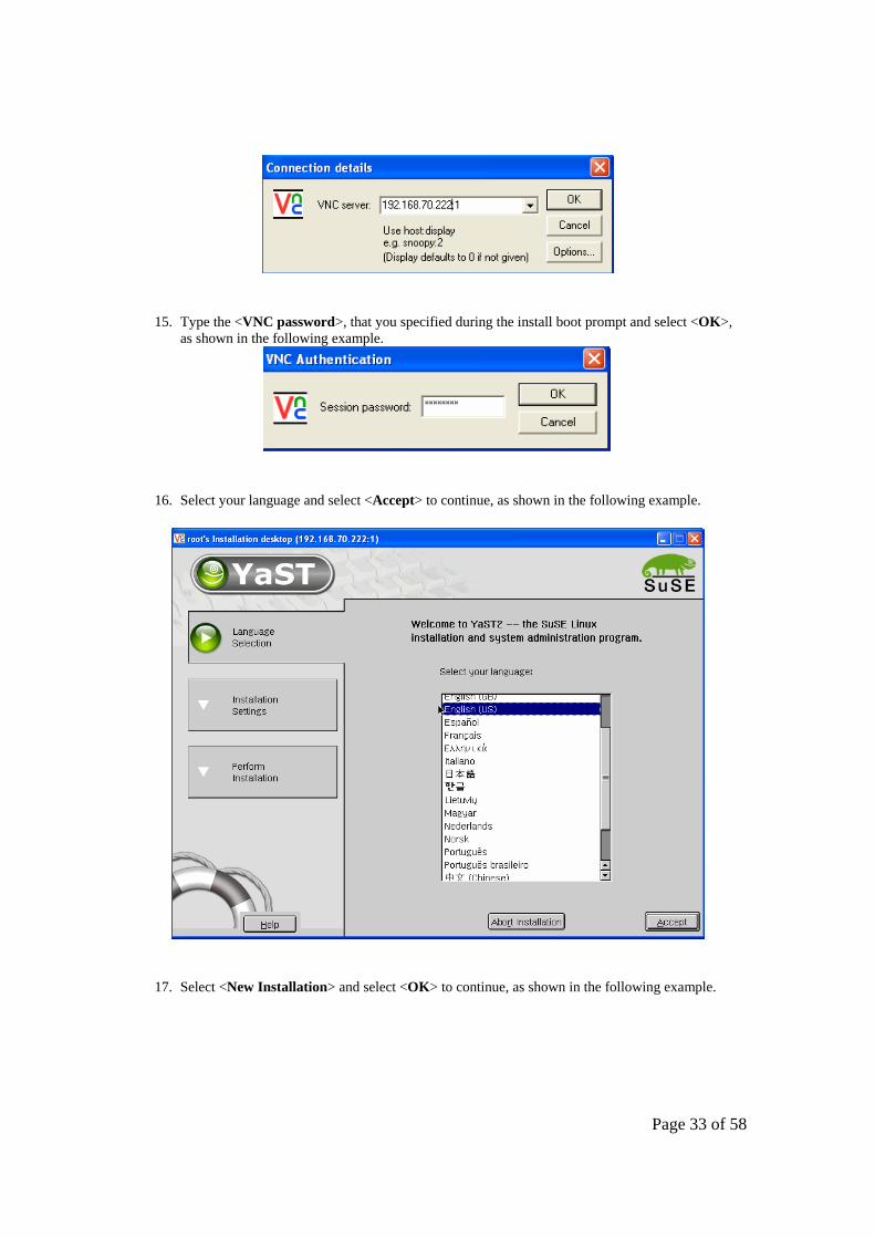
Page 33 of 58
15. Type the <VNC password>, that you specified during the install boot prompt and select <OK>, as shown in the following example.
16. Select your language and select <Accept> to continue, as shown in the following example.
17. Select <New Installation> and select <OK> to continue, as shown in the following example.

Page 34 of 58
18. Make sure that the partition has been configured on /dev/sdbx (where x is the partition number). Customize the Software selection to suit your requirements. Note: hdx is the IDE drive and sdx is the SCSI device, where x is the device number.
19. Select <Accept> to continue, as shown in the following example.

Page 35 of 58
20. Select <Yes, install> to start the installation, as shown in the following example.
21. Insert the SLES8 SP3A CD1 if prompted and select <OK> to continue, as shown in the following example.
22. Server will now reboot. Once rebooted, re-connects using VNC viewer (as previously described) and connect to the VNC server running on the JS20 blade.
23. Set the Linux password and select <Next> to continue, as shown in the following example.
Page 36 of 58
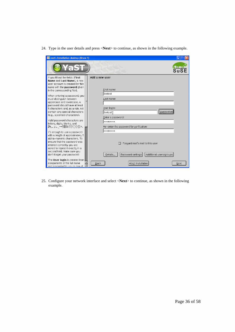
24. Type in the user details and press <Next> to continue, as shown in the following example.
25. Configure your network interface and select <Next> to continue, as shown in the following example.

Page 37 of 58
26. SLES8 has now successfully been installed on the JS20 blade server. Continue to section 14.0 which will guide you through the setup of the boot sequence.
13.2 Installing RHEL3 U3 or later 1. Insert the RHEL3 U3 CD1 in to the CD-ROM drive.
2. Turn on the JS20 blade server.
3. Press the media tray button on the JS20 blade server to assign the media tray to the JS20 blade
server. NOTE: Make sure that local switching of the media tray is not disabled for the JS20 blade server in the management-module Web interface. For more information, see the IBM eServer BladeCenter Management Module User's Guide.
4. Make sure that CDROM is in the CD tray and is assigned to the blade that you are installing. Also, make sure that the bootsequence to boot on CDROM have been configured. Telnet to the management module (MM) and start a SOL session, as shown in the following example.
>telnet 192.168.70.125 username: USERID password: ******** system> console -T blade[4]
5. At the install boot prompt, type:
<linux vnc vncpassword=password> and press enter to continue, as shown in the following example. Also, for text mode install, simply press <enter> instead of supplying the vnc parameters.

Page 38 of 58
6. At the networking device screen, select the second network device (eth1) to configure for VNC, as
shown in the following example..It is highly recommended to not configure ETH0 as Serial Over LAN is using this device.
7. Specify whether you are using DHCP or static. As shown in the following example.

Page 39 of 58
8. Start VNC viewer, once the VNC server has started on the JS20 blade that you are installing. Type
the < IP address:1> (for display 1) of the VNC server running on the blade and select <OK>, as shown in the following example.
9. Type in the <VNC password>, that you specified during the install boot prompt and select <OK>, as shown in the following example.
10. Select <Next> to continue, as shown in the following example.

Page 40 of 58
11. At the “Automatic Partitioning” screen, select <sdb> and select <Next> to continue, as shown in the following example. Note: hdx is the IDE drive and sdx is the SCSI device, where x is the device number.
12. At the “Warning” screen, select <Yes> to continue, as shown in the following example.

Page 41 of 58
13. Verify the partitioning at the “Disk setup” screen and select <Next> to continue, as shown in the following example.
14. Configure your network settings and select <Next> to continue, as shown in the following example.

Page 42 of 58
15. Select whether you want to use firewall or not and select <Next> to continue, as shown in the following example.
16. Select your desired language and select <Next> to continue, as shown in the following example.

Page 43 of 58
17. Select your desired Time Zone and select <Next> to continue, as shown in the following example.
18. Type in root password and select <Next> to continue, as shown in the following example.

Page 44 of 58
19. Select whether you want to customize the package selection or accept default and click <Next> to continue, as shown in the following example.
20. Select the packages that you want to install and click <Next> to continue, as shown in the following example.

Page 45 of 58
21. Select <Next> to finalize the installation and start copy files to your SAN boot device, as shown in the following example.
22. Change CDROM when prompted. Once copying is complete, select <Exit> to exit the installation, as shown in the following example.

Page 46 of 58
23. RHEL3 has now successfully been installed on the JS20 blade server. Continue to section 14.0 which will guide you through the setup of the boot sequence.
14.0 Configuring Boot Sequence and Open Firmware for Remote Boot 1. From the MM interface, change the boot sequence to <Hard Drive 2> as the first boot device, as
shown in the following example.

Page 47 of 58
2. Select <Save> to save your settings and exit from the MM interface. 3. Power on the JS20 blade server and start a SOL session, as described previously in Section 13.x during
the Operating System install. 4. during the boot, at the D5BB prompt, press <8> to enter the Open Firmware prompt. 5. Type <dev/packages/gui> and press enter. Then type <setup-fcp-disk> and press enter to start the
mini SMS, as shown in the following example.
D5BB 4 E1A1 E1A8 ok 0 > dev /packages/gui ok 0 > setup-fcp-disk
6. At the “Main Menu”, select <2> and press enter, as shown in the following example.
pSeries Firmware Version FW04251120 SMS 1.3 (c) Copyright IBM Corp. 2000,2004 All rights reserved. ---------------------------------------------------------------- Main Menu 1. Select Language 2. Select Media Adapter ---------------------------------------------------------------- Navigation Keys: X = eXit System Management Services --------------------------------------------------------------- Type the number of the menu item and press Enter or select Navigation Key:2
7. At the “Select Media Adapter” screen, select <1> and press enter, as shown in the following example.
Select Media Adapter 1. U8842.P1Z.23A0626-P1-C5-T1 /pci@8000000f8000000/pci@1f/fibre-chanel@1 ------------------------------------------------------------- Navigation keys: M = return to Main Menu ESC key = return to previous screen X = eXit System Management Services ------------------------------------------------------------- Type the number of the menu item and press Enter or select Navigation Key: 1
8. At the “Select Device” screen, select your boot drive and press enter to continue, as shown in the
following example.

Page 48 of 58
scan /pci@8000000f8000000/pci@1f/fibre-channel@1/disk@QLogic QLA2312 Fibre Channel Host Adapter fcode version 1.03.13 06/22/04 Firmware version 32.27.06 check /pci@8000000f8000000/pci@1f/fibre-channel@1/disk@21000004cf2fcded,00- pSeries Firmware Version FW04271120 SMS 1.3 (c) Copyright IBM Corp. 2000,2004 All rights reserved. ------------------------------------------------------------- Select Device Device Current Device Number Position Name 1. - SCSI 36401 MB FC Harddisk ( loc=U8842.P1Z.23A0626-P1-C5-T1-L21 000004cf2fcded-L00 ) -------------------------------------------------------------Navigation keys: M = return to Main Menu ESC key = return to previous screen X = eXit System Management Services ------------------------------------------------------------- Type the number of the menu item and press Enter or select Navigation Key: 1
9. At the “Select Task” screen, select <2> for “Normal Mode Boot” and press enter to continue, as shown
in the following example.
pSeries Firmware Version FW04271120 SMS 1.3 (c) Copyright IBM Corp. 2000,2004 All rights reserved. ------------------------------------------------------------- Select Task SCSI 36401 MB FC Harddisk ( loc=U8842.P1Z.23A0626-P1-C5-T1-L21000004cf2fcded-L0 ) 1. Information 2. Normal Mode Boot ------------------------------------------------------------- Navigation keys: M = return to Main Menu ESC key = return to previous screen X = eXit System Management Services ------------------------------------------------------------- Type the number of the menu item and press Enter or select Navigation Key:2 ok 0 >
10. Reboot the blade from the MM interface. The blade should now boot to the OS prompt.
15.0 Configuring for Redundancy Up to this point of configuring Remote boot, these steps have assumed that you were using a
single port of the FC expansion card to perform the OS installation (configured through Port Disable on the switch). The purpose of this was to prevent LUN contention during the OS installation. The next steps will discuss configuring the 2nd port of the FC Expansion card to become useable in the event of a failure on the 1st port. This section will also describe how to configure the second I/O expansion module and install multi-path software etc. This process is used for connecting the secondary path using Storage Partitioning for DS4000 series or provisioning for ESS platforms.

Page 49 of 58
15.1 Enable second switch path Enable the second switch path to the Storage controller, using the steps outlined below. If using OPM, reconnect the FC cable to the OPM in slot 4. Note: In this example, the Storage Subsystem is connected to port 0 on the embedded BladeCenter switch module. Brocade Switch Module Commands Qlogic Switch Module Commands
1. Start a telnet session to the switch 2. Login using ‘USERID’ 3. BSSM: >portEnable 0 4. BSSM: > logout
1. Start a telnet session to the switch 2. FCSM: USERID> admin start 3. FCSM (admin): USERID> config edit 4. FSCM (admin-config): USERID> set
config port 0 5. set port 0 to online 6. FSCM (admin-config): USERID> config
save 7. FCSM (admin): USERID> config activate 8. FCSM (admin): USERID> admin end 9. FCSM (admin): USERID> logout
NOTE: Enable Port 0 on the BladeCenter Switch Modules that was previously disabled to allow only a single path during the installation of the OS. This provides you with dual-paths to the storage controller.
15.2 DS4000 series 1. Add the second WWPN of the FC expansion card to the Storage Partitioning to allow for dual path
to the Storage Subsystem. a. Launch the FAStT client and open the Storage Subsystem that you are configuring for
remote boot. b. Click on the Host that was created in the previous step; select <Mappings>
<Define> <Host-port>s. Each Host should initially have a single host-port assigned. Otherwise, the host will have dual-path access assigned. The host port is the Adapter WWPN that you recorded while configuring the FC Expansion card. The host type for each of these host-port types will be Windows® Non-clustered by default and should be changed to correspond to the Operating system type that you will be installing.
2. Auto-volume transfer/auto-disk transfer (AVT/ADT) is a function that provides automatic failover
in case of controller failure on a storage subsystem. This function has to be enabled on the DS4000 series controller in a remote boot environment. Enable AVT for the DS4000 series Storage Controller using the following script sample. For information on how-to load DS4000 series script, see your DS4000 series documentation.
Linux configuration
3. (LINUX only) Install the IBM FAStT Management Suite Java (MSJ) for failover capability as directed below. NOTE: The FAStT MSJ application should be compatible with the Firmware that is being used on the Storage controller. You can confirm this by referring to the FAStT MSJ and Firmware Readme files.
Enabling AVT on DS4000 series // The following commands Enable AVT // You must reboot the controllers for the NVSRAM settings to take effect set controller[a] NVSRAMByte[0x33]=0x40,0x40; set controller[b] NVSRAMByte[0x33]=0x40,0x40;

Page 50 of 58
a. Obtain the latest FAStT MSJ from the IBM support website (http://www-1.ibm.com/servers/storage/support/fastt/index.html)
b. Telnet and log on as root to the JS20 blade Server.
c. Copy the FAStT MSJ to the JS20 blade server.
d. Change to the directory that contains the FAStT MSJ installer.
e. At the prompt , type <sh FAStTMSJ_install.bin -i silent>. FAStT installs in the /opt
directory. The launch script is located in the /usr directory.
4. (LINUX only) Run the IBM FAStT Management Suite Java (MSJ). Note: The default FAStT MSJ password is "config". Make sure you change this password after installation to ensure that security is not compromised. To enter a new Password you must have Administrative Privileges. You cannot perform management functions and NVRAM\Flash modification unless you set a Password for FAStT MSJ.
a. Ensure that you are in a graphical user environment.
b. Start qlremote, open a command terminal from the root directory and type <qlremote>.
c. Change to the usr directory in which the IBM FAStT MSJ script is installed, by typing
<cd /usr>
d. Start the application, by typing <./FAStT_MSJ>
e. When FAStT MSJ is no longer required, enter ctrl-c and close the terminal window where qlremote is running. To ensure that qlremote has been successfully terminated do the following: From a command terminal type: killall -TERM qlremote. You should get a "no process killed" message. Note: Ensure that no I/O's are occurring when qlremote is running.
f. Please refer to the online help file or the User's Guide for more information. To view the
online help, go to Help and "Set Browser Location" to match the location where your preferred browser is located. You may now browse the Help file by selecting "Browse Contents".
5. (LINUX only) Configure the IBM FAStT Management Suite Java (MSJ) for failover capability.
Use the Auto Configure option to configure all device paths for the selected host to the default values for failover. The default path for each device is the first available path as visible, with the other paths hidden. This option prompts for the automatic configuration of LUNs associated with these devices. Perform the following steps to configure the device paths, and optionally the LUN paths, on this host to default values. Note: If required, consult the FAStT MSJ User’s Guide for guidance on how-to manually configure the failover.
a. From the Fibre Channel Port Configuration window, click <Tools> -> <Auto
Configure>. b. The system prompts whether you also want to use default LUN configurations. Click
<Yes> to change the current LUN configurations to the default values.

Page 51 of 58
c. Verify that paths have been setup and that it can see both paths, by right-clicking the cell for the device in the Adapter n column. Verify the path information in the “Path Information window”.
d. Exit and close the MSJ application.
e. When FAStT MSJ is no longer required, enter ctrl-c and close the terminal window
where qlremote is running. To ensure that qlremote has been successfully terminated do the following: From a command terminal type: killall -TERM qlremote. You should get a "no process killed" message. Note: Ensure that no I/O's are occurring when qlremote is running.
AIX configuration
6. (AIX only) Install the RDAC file sets for failover capability.
a. Verify that all pre-req’s for the RDAC file sets has been installed by consulting the latest AIX RDAC User’s Guide.
b. Download the most recent AIX RDAC file sets from the following IBM Web site:
techsupport.services.ibm.com/server/aix.fdc.
c. Telnet and log on as root to the JS20 blade Server.
d. Probe for new devices by typing <cfgmgr –v>.
e. Copy the AIX RDAC file sets to the JS20 blade server.
f. From the command prompt, type <smitty install_update> and press enter to go directly to the installation panels. The “Install and Update Software” menu is displayed.
g. Select <Install Software> and press enter.
h. Press <F4> to display the “INPUT Device/Directory for Software” panel.
i. Type in the directory path to where RDAC filesets was copied to and press enter.
j. Press Enter again. “The Install Software” panel is displayed.
k. Select Software to Install and press <F4>. The “Software to Install” panel is displayed.
l. Select the installation package that is appropriate for your environment.
m. Press Enter. The “Install and Update from LATEST Available Software” panel is
displayed with the name of the software that you selected to install.
n. Check the default option settings to ensure that they are what you need.
o. Press enter to install.
p. Press enter to continue. Note: The installation process can take several minutes to complete.
q. When the installation is complete, press <F10> to exit from SMIT.

Page 52 of 58
r. Run and examine the output of the <lsdev -Cc disk> command to ensure that the RDAC software recognizes the FAStT logical drives that has been assigned to the JS20 blade server.
15.3 ESS
1. Add the second WWPN of the FC expansion card to the Storage Partitioning to allow for dual path to the Storage Subsystem.
a. Using ESS Specialist, modify the Host System to include the 2nd HBA and Boot LUN.
b. Enter the information in the text fields for the 2nd port of the FC Host adapter and Boot LUN.
c. Save the configuration and proceed to enabling the path through the Switch Module.
Linux configuration
2. (LINUX only) Install the SDD multi-path device driver using the Linux RPM or AIX installation
package. NOTE: You should reference the SDD User’s to properly plan your installation. This can be found at: : http://www-1.ibm.com/servers/storage/support/software/sdd.html
a. Obtain the latest version of SDD for Linux from the IBM SDD support website
(http://www-1.ibm.com/servers/storage/support/software/sdd.html) b. Telnet and log on to the JS20 blade server as the root user.
c. Copy the SDD package to the JS20 blade server. d. Type <rpm -Uvh IBMsdd-xxxxx.rpm> to install SDD, where xxxx represents the
current version release modification level number.
e. Verify that the JS20 blade server can see both paths using and examining the <datapath query device> command from the command line. NOTE: See the SDD User Guide for more information.
AIX configuration
3. (AIX only) Install the SDD file sets for failover capability.
a. Verify that all pre-req’s for the SDD file sets has been installed by consulting the latest SDD User’s Guide.
b. Download the most recent SDD file sets from the following IBM Web site (http://www-
1.ibm.com/servers/storage/support/software/sdd.html)
c. Telnet and log on as root to the JS20 blade Server.
d. Probe for new devices by typing <cfgmgr –v>.
e. Copy the AIX SDD file sets to the JS20 blade server.

Page 53 of 58
f. From the command prompt, type <smitty install_update> and press enter to go directly to the installation panels. The “Install and Update Software” menu is displayed.
g. Select <Install Software> and press enter.
h. Press <F4> to display the “INPUT Device/Directory for Software” panel.
i. Type in the directory path to where SDD filesets was copied to and press enter.
j. Press enter again. “The Install Software” panel is displayed.
k. Select Software to Install and press <F4>. The “Software to Install” panel is displayed.
l. Select the installation package that is appropriate for your environment.
m. Press Enter. The “Install and Update from LATEST Available Software” panel is
displayed with the name of the software that you selected to install.
n. Check the default option settings to ensure that they are what you need.
o. Press enter to install.
p. Press enter to continue. Note: The installation process can take several minutes to complete.
q. When the installation is complete, press <F10> to exit from SMIT.
r. Verify that the JS20 blade server can see both paths using and examining
the <datapath query device> command from the command line. NOTE: See the SDD User Guide for more information.
16.0 Installing Service Aids and Updating the Open Firmware on JS20
After installation of the Operating System, you must download and install the Service Aids for Hardware Diagnostics. This service aids toolkit provides the tools required to service and update JS20 blade systems running IBM's supported versions of the Linux operating system. In the rare instance when a system error occurs, the toolkit provides first failure data capture, error log analysis, and other necessary information needed for accurate problem determination and correction.
1. Download and install the Service Aids for Linux, these utilities and instructions can be found at: http://techsupport.services.ibm.com/server/lopdiags
2. Obtain the latest JS20 Open Firmware level (JSFWxxx.IMG) from the IBM support site
(http://www.pc.ibm.com/support).
3. Telnet and login as root to the JS20 blade server.
4. Copy the latest version of the Open Firmware that you obtained from the IBM support site to the JS20 blade server.

Page 54 of 58
5. Type < update_flash –f filename> command to upgrade the open firmware of the JS20 blade. NOTE: The update_flash utility will immediately reboot the server when the temporary image is flashed.
6. After the JS20 blade has successfully rebooted, log in as root and promote the flash to the
temporary side. This is done, using the <update_flash –c > command. Options available with the “update_flash” command are:
Update_flash usage Usage: update_flash [-q] { -r | -c | [-v] -f <filename> } -r Reject temporary image -c Commit temporary image -v Validate ONLY with specified image file working -f <filename> Update firmware with specified image file
Page 55 of 58
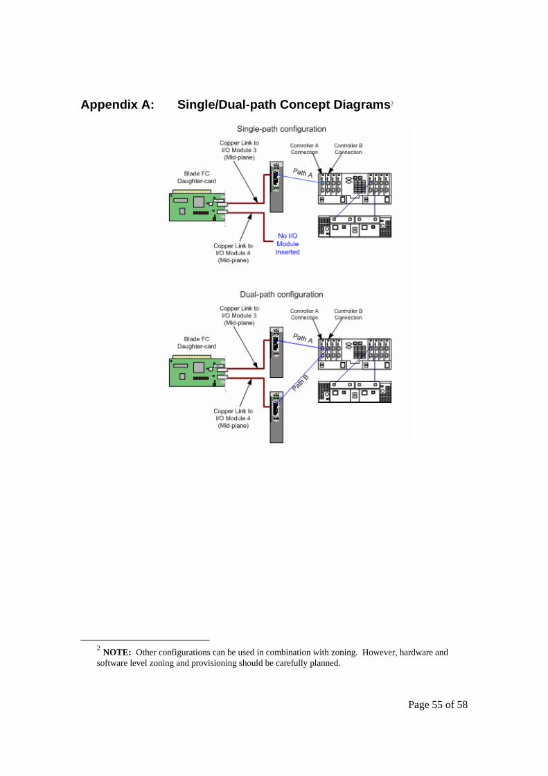
Appendix A: Single/Dual-path Concept Diagrams2
2 NOTE: Other configurations can be used in combination with zoning. However, hardware and software level zoning and provisioning should be carefully planned.

Page 56 of 58
Appendix B: BladeCenter SAN Options Equipment List Note: The following I/O Expansion card option is supported for Remote booting with the JS20 (8842)
Blade: 73P6112. Options 13N2203 and 48P7061 are supported in the JS20. However, they are not boot capable.
Option Number Description Option Number Description
13N2203 BladeCenter Fibre Channel Expansion Card. Note this card does not support JS20 remote boot.
26K6477 Qlogic 6-port Enterprise Fibre Channel Switch Module (Qlogic SANBox 5200 Equivalent)
73P6112 BladeCenter Fibre Channel Expansion Card. This card supports JS20 remote boot.
48P7062 BladeCenter 2-port Fibre Channel Switch Module2 (Qlogic SB2- 16 Equivalent)
19K1271 Short-wave SFP Module
26K5601 Brocade Entry SAN Switch Module for IBM BladeCenter
19K1272 Long-wave SFP Module
90P0165 Brocade Enterprise SAN Switch Module for IBM BladeCenter
19K1247 1m LC-LC Fibre Channel Cable
02R9080 BladeCenter Optical Pass-thru Module
19K1248 5m LC-LC Fibre Channel Cable
26K5618 Brocade Entry Switch Full SAN Upgrade for IBM eServer BladeCenter
19K1249 25m LC-LC Fibre Channel Cable
26K5613 Brocade Extended Fabrics for IBM eServer BladeCenter
19K1250 LC-SC Fibre Channel Adapter Cable (Note: 1)
26K5605 Brocade Performance Bundle for IBM eServer BladeCenter
73P6033 BladeCenter Optical Pass-thru Module LC Cable
Note: You should contact the Field Sales Rep for other options that may have become available.

Page 57 of 58
Summary This paper provides an overview for configuring the IBM BladeCenter JS20 to remote boot in the Linux and AIX operating environments. These steps are typically performed by seasoned Storage Administrators with requisite knowledge of the DS4000 series and ESS Storage products. However, this document has sought to provide guidance for the novice SAN Administrator to follow and successfully accomplish this task. One should keep in mind that this provides a general guideline for configuring remote boot and any effort to create a remote boot environment should be well planned.
Additional Information For more information about blade server technology and benefits in general and BladeCenter specifically, read Why Blade Servers? and Slashing the costs of your IT Infrastructure, at http://www.ibm.com/pc/us/eserver/xseries/bladecenter/more_about.html. Visit http://www.ibm.com/servers/eserver/blades (or call 1-888-SHOPIBM) for information about IBM eServer BladeCenter products and services, including part numbers and prices for servers, racks, storage units and other options.

Page 58 of 58
© IBM Corporation 2004 IBM Systems Group Department AE3A Research Triangle Park NC 27709 Produced in the USA 2-04 All rights reserved IBM, the IBM logo, the e-business logo, Active PCI, Active PCI-X, Electronic Service Agent, eLiza, HelpCenter, LANClient Control Manager, OnForever, OS/2, Predictive Failure Analysis, ServerGuide, ServeRAID, Tivoli, Wake on LAN, X-Architecture and xSeries are trademarks of IBM Corporation in the United States and/or other countries. Intel is a registered trademark of Intel Corporation. Linux is a registered trademark of Linus Torvalds. Microsoft, Windows, Windows NT and the Windows logo are trademarks or registered trademarks of Microsoft Corporation. Other company, product, and service names may be trademarks or service marks of others. IBM reserves the right to change specifications or other product information without notice. IBM makes no representations or warranties regarding third-party products or services. References in this publication to IBM products or services do not imply that IBM intends to make them available in all countries in which IBM operates. IBM PROVIDES THIS PUBLICATION “AS IS” WITHOUT WARRANTY OF ANY KIND, EITHER EXPRESS OR IMPLIED, INCLUDING THE IMPLIED WARRANTIES OF MERCHANTABILITY AND FITNESS FOR A PARTICULAR PURPOSE. Some jurisdictions do not allow disclaimer of express or implied warranties in certain transactions; therefore, this statement may not apply to you. IBM eServerTM xSeries servers are assembled in the U.S., Mexico, Great Britain, Japan, Australia and Brazil and are composed of U.S. and non-U.S. parts. This publication may contain links to third party sites that are not under the control of or maintained by IBM. Access to any such third party site is at the user's own risk and IBM is not responsible for the accuracy or reliability of any information, data, opinions, advice or statements made on these sites. IBM provides these links merely as a convenience and the inclusion of such links does not imply an endorsement.