Predictions About the Future - ESC | Congresses | ESC Congress

En
gin
eeri
ng
Sta
nd
ard
STRUCTURES SYSTEM
ESC 300
Engineering Standard Civil
Version 2.3
Issued February 2011
Owner: Chief Engineer Civil
Approved John Stapleton Authorised Richard Hitch by: Principal Engineer Technology by: Chief Engineer Civil
& Standards
Disclaimer
This document was prepared for use on the RailCorp Network only.
RailCorp makes no warranties, express or implied, that compliance with the contents of this document shall be sufficient to ensure safe systems or work or operation. It is the document user’s sole responsibility to ensure that the copy of the document it is viewing is the current version of the document as in use by RailCorp.
RailCorp accepts no liability whatsoever in relation to the use of this document by any party, and RailCorp excludes any liability which arises in any manner by the use of this document.
Copyright
The information in this document is protected by Copyright and no part of this document may be reproduced, altered, stored or transmitted by any person without the prior consent of RailCorp.
UNCONTROLLED WHEN PRINTED Page 1 of 29

RailCorp Engineering Standard — Civil Structures System ESC 300
Document control
Version Date Summary of change 2.3 February, 2011 Changes detailed in Summary table below
2.2 July, 2010 Change of format for front page, change history and table of contents; 4.3: change TMC 304 to SPC 301
2.1 November, 2009 Change of format; minor editing
2.0 July, 2007 Minor changes in 5.2 re integrated designs, anti-graffiti coatings, not to use safe working colours when painting structures, provide safe access for inspection & maintenance, approved materials; New 5.3 re RailCorp standard construction specifications; Definition of kilometrage value included in Section 9. Replaces CTN 06/14 “Withdrawal of Old Standard Plans Bridges & Structures”.
1.0 March, 2006 First issue as a RailCorp document. Includes content from TS 4151
Summary of c hanges from previous version
Summary of change Section
Minor editing throughout All
Update definition for tunnels to make consistent with ESC 340; delete definitions for minor opening; overhead loading structures and unloading bins
3
New section on Heritage 4.2
Additional explanation on numbering of bridge members 7
Add definitions for cross girder; span; stringer girder App A
New Appendix on bridge numbering App B
© RailCorp Page 2 of 29 Issued February 2011 UNCONTROLLED WHEN PRINTED Version 2.3

RailCorp Engineering Standard — Civil Structures System ESC 300
Contents
1 Purpose, Scope and Application...........................................................................................4
2 References...............................................................................................................................4
2.1 Australian and International Standards.....................................................................................4
2.2 RailCorp Documents .................................................................................................................4
2.3 Other References......................................................................................................................4
3 Bridge and Structure Categories...........................................................................................4
4 Bridge and Structure Policies................................................................................................5
4.1 General......................................................................................................................................5
4.2 Heritage.....................................................................................................................................6
4.3 Design .......................................................................................................................................6
4.4 Construction ..............................................................................................................................7
4.5 Maintenance..............................................................................................................................7
4.6 Standard Plans..........................................................................................................................7
5 Description of Bridges and Structures .................................................................................8
6 Bridge Spans ...........................................................................................................................8
6.1 Length .......................................................................................................................................8
6.2 Types.........................................................................................................................................8
6.2.1 Deck...........................................................................................................................8
6.2.2 Through......................................................................................................................8
6.2.3 Truss..........................................................................................................................8
7 Numbering of Bridge Members .............................................................................................8
7.1 Underbridges.............................................................................................................................8
7.2 Overbridges and Footbridges ...................................................................................................9
8 Location of Bridges and Structures......................................................................................9
Appendix A Terms Used In Bridges and Structures ...............................................................11
Appendix B Bridge Numbering .................................................................................................15
Appendix C Typical Bridge Spans and Members....................................................................16
Appendix D Withdrawn Standard Plans ...................................................................................28
© RailCorp Page 3 of 29 Issued February 2011 UNCONTROLLED WHEN PRINTED Version 2.3

RailCorp Engineering Standard — Civil Structures System ESC 300
1 Purpose, Scope and Application This Standard sets out the high-level engineering policies for the design, construction and maintenance of bridges and structures on the RailCorp network, together with the conventions adopted for describing types of bridges and structures and their individual members.
2 References
2.1 Australian an d Inter national Standards AS 5100 - Bridge design
2.2 RailCorp Documents ESC 215 - Transit Space
SPC 301 - Structures Construction
2.3 Other R eferences Environmental Planning and Assessment Act
Heritage Act
Occupational Health & Safety Act
Rail Safety Act
3 Bridge and Structure Categories Bridges owned and maintained by RailCorp fall into three (3) general categories:
Underbridges: These are bridges supporting the track and passing over waterways, roadways, pathways, flood plains, etc. Underbridges include viaduct, flyover, subway and culvert structures.
The term ‘viaduct’ is used to refer to underbridges in excess of 100 metres in length.
The term ‘flyover’ is used to refer to a bridging structure where one rail track passes over another rail track that is located at ground level.
The term ‘subway’ is used to refer to an underbridge that passes over a pedestrian pathway.
The term ‘culvert’ is used to refer to minor ballast-top openings comprising metal pipes, concrete pipes, concrete boxes, concrete arches, brick and masonry arches.
Overbridges: These are bridges carrying road vehicles or livestock over the track, and may include provision for pedestrians.
Footbridges: These are bridges over the track carrying pedestrian traffic only, and may be freestanding or combined with an overhead booking office.
In addition to bridges as defined above, there are specific categories of other structures on RailCorp’s network crossing over, under or adjacent to the track:
© RailCorp Page 4 of 29 Issued February 2011 UNCONTROLLED WHEN PRINTED Version 2.3

RailCorp Engineering Standard — Civil Structures System ESC 300
Tunnels: A space through which one or more rail tracks pass, which is continuously enclosed above, below and on both sides.
These are structures constructed either through high terrain that enables the rail track to continue at an acceptable grade, or in metropolitan areas where above ground rail track is not feasible. It may be constructed by boring or by cut and cover. It may be fully lined or unlined (depending on the stability of the natural ground) and may be constructed with drainage systems, ventilation shafts and safety refuges.
For fire safety purposes, a tunnel is a space through which one or more rail tracks pass, which is continuously enclosed above, below and on both sides and is in excess of 80 m in length. An air space development providing enclosure of 80 m in length to a previously open track also forms a railway tunnel.
A ‘dive’ is a form of tunnel where one rail track passes under another track that is located at ground level.
Overbridges built to accommodate wide or skewed roadways are not defined as tunnels.
Retaining Walls: Retaining walls are constructed to protect the rail track from subsidence or land slips and are typically provided in cuttings or on narrow embankments. They are also constructed in areas where natural ground batters and the necessary cess width are not possible owing to the limited width of the railway easement. They are typically constructed in timber, masonry, concrete, steel sheeting, reinforced earth or rails and sleepers.
Station Platforms: These are line-side structures built to provide public access to passenger trains.
Air Space Developments: These are structures built over the rail track to support overhead offices, shops and accommodation etc.
Overhead Wiring Structures: Portal structures or masts built to support the overhead traction wiring.
Signal Gantries: Portal structures built to support signals over the tracks. May also support overhead wiring.
Buffer Stops: These are structures provided at the end of rail lines or sidings to prevent rolling stock from running off the end of the track and/or colliding with adjacent structures.
Service Crossings: These are structures carrying commercial product or utilities over or under the tracks and across the railway corridor.
Rockfall Shelters: Rockfall shelters are structures installed over and beside a rail track to prevent loose material from adjacent cuttings falling on to the rail line.
Lighting and Communication Towers: These are structures installed beside a rail line for the purpose of supporting overhead lighting and aerial communication lines.
4 Bridge and Structure Policies
4.1 General All bridges and structures within the RailCorp network shall be designed, installed and maintained in a condition appropriate to the traffic task and safe operations, at the lowest overall life-cycle and operational cost.
© RailCorp Page 5 of 29 Issued February 2011 UNCONTROLLED WHEN PRINTED Version 2.3

RailCorp Engineering Standard — Civil Structures System ESC 300
Mandatory obligations for the design, construction, maintenance and disposal of bridge and structure assets will be met through compliance with safety, statutory and regulatory requirements and Australian Standards. Applicable legislation includes the Rail Safety Act, the Occupational Health & Safety Act, the Environmental Planning and Assessment Act and the Heritage Act.
4.2 Heritage Heritage considerations and classifications shall be observed in all designs. This may have particular application in circumstances where:
• an existing structure is being refurbished or modified • a new structure is being proposed in the vicinity of existing heritage items • a redundant structure is to be demolished.
RailCorp maintains a database of heritage assets in accordance with section 170 of the Heritage Act. The RailCorp Section 170 Register can be found on the Intranet site and the Internet site at http://www.railcorp.info/community/heritage_register
The Heritage Branch of NSW Department of Planning maintains a State Heritage Inventory. The State Heritage Inventory is available on their website at www.heritage.nsw.gov.au.
These registers shall be referenced before planning any changes to structures assets to ensure changes comply with the requirements of the NSW Heritage Act.
4.3 Design The design of all new or replacement bridges and structures will take into account:
• Service loads and current/ known future operating requirements; • Environmental conditions (e.g. coastal environments); • Impact and derailment protection where applicable; • RailCorp’s Transit Space Standards; • Life-cycle costs.
Bridges shall be designed for a design life of 100 years, in accordance with AS 5100 “Bridge design”.
Other structures shall be designed for the design life specified in the relevant standard for each category of structure.
The design of each bridge and structure is to be integrated taking into account all associated requirements such as service routes, overhead wiring and signalling infrastructure, drainage, bonding and architectural treatments. Where appropriate, aesthetics are to be taken into account including proportions, details and finishes.
In locations that are vulnerable to vandalism and graffiti, appropriate measures are to be taken to discourage access to the bridge. Anti-graffiti coatings should be specified in areas where there is a high risk of graffiti.
Trackside structures shall not be painted in safeworking colours of red, orange and green.
Designs for structures shall provide safe access for inspection and maintenance. This may include access steps, ladders, cages, walkways and fixing points.
The area extending one metre below design rail level of Normal Structure Gauge 1994 as detailed in RailCorp Engineering Standard - ESC 215 Transit Space shall be kept clear of structures and structure footings.
© RailCorp Page 6 of 29 Issued February 2011 UNCONTROLLED WHEN PRINTED Version 2.3

RailCorp Engineering Standard — Civil Structures System ESC 300
When modifying or replacing line-side or overhead structures, clearances, track centres and shoulder widths should be increased to the current standards to the maximum extent possible given practical restraints at the site. Where current standards cannot be achieved the approval of the Chief Engineer Civil shall be obtained.
Approved construction materials for main structural elements are steel and concrete. Masonry is approved for existing structures. With the exception of bridge transoms, timber materials will not be used as structural elements in the design of new bridges and structures.
Fibre composite and engineered timber products may be used subject to the approval of the Chief Engineer Civil.
4.4 Construction Standard construction specifications shall be used for the manufacture, fabrication, erection and installation of bridge and structures components, and the construction of associated civil works.
RailCorp has a suite of technical specifications for construction of bridges and structures. The specifications are detailed in RailCorp Engineering Specification SPC 301 Structures Construction and are to be incorporated in the design and construction documentation of structures. The specifications generally adopt the Roads and Traffic Authority (RTA) QA Specifications as posted on the RTA web site. The specifications include specific RailCorp requirements where necessary.
4.5 Maintenance Major assets in service such as steel truss bridges, long viaducts and tunnels will be maintained and preserved for an indefinite service life.
Deterioration limits (to be referred to as Defect Limits) will be set for individual bridge members, for use by examination and maintenance personnel. A Mandatory Response will also be set for each Defect Limit found, ranging from recording for future information and action to immediate closure of the track.
Technical Maintenance Plans (TMP) and Service Schedules (SS) will be prepared and implemented for all bridge and structure assets, specifying which items are to be maintained, what maintenance is to be carried out and when maintenance is required.
4.6 Standard Plan s Over the years Standard Plans have been developed for many rail assets. Many of the plans have been superseded with the development of new standards.
Books of Standard Plans are still in existence in some offices. The Standard Plans are available in the Plan Room. Whilst this is necessary for the maintenance of old assets originally built to the plans, the plans are generally not suitable for use in the design of new assets.
The Standard Plans listed in Appendix 4 are withdrawn from use for design of new assets and refurbishment/upgrading of existing assets. Plans may be used on particular projects if approval is obtained from the Chief Engineer Civil.
© RailCorp Page 7 of 29 Issued February 2011 UNCONTROLLED WHEN PRINTED Version 2.3

RailCorp Engineering Standard — Civil Structures System ESC 300
5 Description of Bridges and Structures Terms used to describe individual members of bridges and structures are listed in Appendix 1. Sketches of typical bridge spans and members are shown in Appendix 2.
6 Bridge Spans
6.1 Length The length of bridge spans is measured and described as follows:
• Steel bridges: distance between centres of bearings • Concrete bridges: distance between centres of bearings • Brick and Stone bridges: distance between faces of piers • Timber bridges: distance between centres of headstocks.
For bridges with an integral deck, walls, and invert (e.g. box culverts, arch culverts, box drains and pipes), the span length is measured between faces of walls.
Skew spans are measured generally parallel to the supported track or road.
6.2 Types There are three (3) types of bridge span:
6.2.1 Deck
Has track on top with no parts of bridge above rail height.
6.2.2 Through
Any type of bridge that has sides above the level of the track with no parts on top joining the sides.
6.2.3 Truss
A bridge made up of a number of parts and forms a box type shape and trains pass through the centre.
7 Numbering of Bridge Members Numbering of bridge members follows the same pattern for underbridges, overbridges, and footbridges.
Bridge members are: abutments, piers/trestles, spans, girders, cross girders, stringers, corbels, headstocks, sway bracing and wind bracing.
For truss bridges, members also include top chord, bottom chord, diagonals and verticals.
Refer to Appendix A Terms used in Bridges and Structures for definitions.
7.1 Underbridges For underbridges, the Sydney end abutment is the datum for numbering, being the No. 1 Abutment.
© RailCorp Page 8 of 29 Issued February 2011 UNCONTROLLED WHEN PRINTED Version 2.3

RailCorp Engineering Standard — Civil Structures System ESC 300
The numbering system for bridge components starts at the Sydney end of the bridge.
For members running across ways, e.g. abutments, spans, piers cross girders, sway braces and transoms, the numbers start at number 1 at the Sydney end abutment and continue sequentially towards the country end of the bridge.
These members are numbered as follows:
• Abutments: No. 1 closer to Sydney, No. 2 other end of bridge. • Abutment Wings: No. 1 (Down) and No. 2 (Up) for No. 1 Abutment. No. 3 (Down)
and No. 4 (Up) for No. 2 Abutment. • Spans: No. 1 is the first span from the Sydney end abutment; and then numbered
away from Sydney • Piers/Trestles: No. 1 closest to No. 1 Abutment, others in sequence. • Cross Girders: from the Sydney end of each span. • Sway bracing: from the Sydney end of each span. • Transoms: numbered sequentially from No. 1 abutment.
For bridge components running length wise, e.g. girders, stringers, piles, corbels, and wind braces, the numbering is from left to right when standing with your back to Sydney facing the bridge.
These members are numbered as follows:
• Piles: From the Down side of each Abutment/Trestle/Pier. • Girders, Stringers, Corbels: From the Down side of each span. • Wind bracing: from the Sydney end of each span.
Refer to Appendix B Bridge Numbering for a diagram of the above for an underbridge.
7.2 Overbridges and Fo otbridges For overbridges and footbridges, the Down side Abutment is the datum for numbering, i.e. the No. 1 Abutment.
The numbering system for bridge components starts at the down side abutment. Bridge members then are numbered as for an underbridge i.e from number one abutment to number 2 abutment, and from left to right when standing at number 1 abutment facing the bridge.
8 Location of Bridges and Structures All bridges and structures are to have a kilometrage (correct to 3 decimal places) stencilled in 75mm high black figures on a white background, or engraved on a plaque.
The kilometrage value is generally the value at the face of the structure on the Sydney end. For bridges and culverts, the kilometrage value is as follows:
• Underbridges: the km value at the face of the Sydney end abutment under the centreline of the furthest Down track.
• Culverts: the km value at the centreline of the culvert or the Sydney side centreline of a group of culverts.
• Overbridges and Footbridges: the km value where the Sydney side of the bridge crosses the track.
The stencilled kilometrage is to be located as shown:
Underbridges: on the Up side of the No. 1 abutment and on the Down side of the No. 2 abutment. Underbridges less than 10 metres long are to be stencilled on the No. 1
© RailCorp Page 9 of 29 Issued February 2011 UNCONTROLLED WHEN PRINTED Version 2.3

RailCorp Engineering Standard — Civil Structures System ESC 300
abutment only. Bridges without defined abutments, e.g. some culvert structures, are to be stencilled on the face of the Down side headwall.
Overbridges and Footbridges: on the abutment or pier adjacent to the furthest Down track and at the Sydney end.
Tunnels: on the Down side of the No. 1 portal, and on the Up side of the No. 2 portal.
Platforms: on the face of the coping at each end of No. 1 platform.
Overhead Wiring and Signal Structures: in accordance with conventions implemented by electrical and signalling disciplines.
Other Structures: on the Down side of the track and at the Sydney end.
© RailCorp Page 10 of 29 Issued February 2011 UNCONTROLLED WHEN PRINTED Version 2.3

Appendix A Terms Used In Bridges and Structures
A
ABUTMENT The support at each end of a bridge.
APPROACH SLAB Slab (usually reinforced concrete) laid above the formation behind bridge abutments and designed to provide a transition zone for
track stiffness onto the bridge.
B
BALLAST LOG Member usually timber, sitting on top of the abutment wall to hold back track ballast.
BALLAST TOP Underbridge with continuous deck supporting metal ballast.
BALLAST WALL Member laid longitudinally at the outer edge of a ballast top span to prevent ballast spilling over the side.
BARRIER The fence or walls along the sides of overbridges and footbridges, installed to protect road vehicles, cyclists and pedestrians from
falling over the edge of the bridge.
BEARING Seating area of a load-carrying member; may be a separate fabricated member attached to the girder ends.
BODY BOLT Vertical bolt in timber girders and corbels causing pairs of members to deflect together.
BRACING Horizontal or diagonal member attached to main members to stiffen those members, or to minimise sidesway.
BRIDGE A structure spanning a river, road, railway, or the like, and carrying vehicles or persons. Consists of a substructure and a
superstructure.
BROAD FLANGE BEAM A steel girder designed in the 1920’s with thicker and wider flanges and reduced height of web for use in locations where greater vertical clearance was required.
BUFFER STOP Structure provided at the end of a rail line or siding to prevent rolling stock from running off the end of the track and/or colliding
with an adjacent structure. May be fixed or energy absorbing type.
C
CAPPING Semi-impermeable layer of fill located immediately above the main formation and designed to shed water to the sides of the track.
CATCHMENT Area of land from which water flows into an underbridge.
COMPOUND GIRDER Timber girder made from two or more sections bolted firmly together on top of each other.
COPING The longitudinal edge of a station platform.
CORBEL Short longitudinal member seated on a headstock providing a bearing for adjacent girders.
CRACK Open fissure on the surface of a member, but not necessarily right through the member.
CROSS GIRDER Load-bearing member of a structure that runs transverse to the direction of traffic.
CULVERT Arch, box-shaped or piped underbridge having integral walls, roof and floor.
D
RailCorp Engineering Standard — Civil Structures System ESC 300
© RailCorp Page 11 of 29 Issued February 2011 UNCONTROLLED WHEN PRINTED Version 2.3
DEBRIS Rubbish or other loose material lying near an underbridge and which impedes smooth water flow through the bridge opening.
DECAY Deterioration on or in a timber member causing loss of strength.
DECK Part of bridge superstructure directly carrying the load.
DEFLECTION Downwards displacement or sag of a girder when loaded by vehicles or persons.
DEFLECTION WALL Structural wall installed to protect the supports of a structure adjacent to the track from collapse caused by a derailed train.
DIVE Form of tunnel where one rail track passes under another track that is located at ground level
DRIVING MARK Mark cut into (timber) pile indicating in roman numerals the distance to the pile tip.
F
FLOOD LEVEL Mark stencilled on No.1 Abutment of underbridges indicating height and date of maximum previous flood.
FOOTBRIDGE Bridge over the track carrying pedestrian traffic only. May be freestanding or combined with an overhead booking office.
FORMATION Ground immediately beneath the capping and track.
FLYOVER Bridging structure where one rail track passes over another which is at ground level.
G
GIRDER Main horizontal load-bearing member of a structure.
GUARD RAIL Rail placed in pairs and fixed to transoms or sleepers between the running rails, to guide the wheels of a derailed train.
H
HANDHOLD DEVICE A system of handrails provided along a wall structure to provide support for personnel.
HEADSTOCK Horizontal member(s) attached at or near the top of a trestle or pier, on which the superstructure bears.
I
INVERT Earth or concrete floor of an underbridge.
J
JACK ARCH Form of bridge decking in which small concrete or masonry arches infill run between main longitudinal steel girders.
M
MINOR OPENING Underbridge less than 10 metres in length.
O
OBVERT Underside of bridge superstructure.
OVERBRIDGE Bridge carrying road vehicles or livestock over a track.
P
PACKING Piece of timber, steel, or other hard material, placed or driven between members to adjust their relative position.
PARAPET A type of barrier comprising a solid wall or post and rail fence along the sides of overbridges and footbridges, installed to protect
road vehicles, cyclists and pedestrians from falling over the edge of the bridge.
PIER Intermediate support of bridge spans between abutments, built of solid construction and usually in concrete or masonry.
RailCorp Engineering Standard — Civil Structures System ESC 300
© RailCorp Page 12 of 29 Issued February 2011 UNCONTROLLED WHEN PRINTED Version 2.3

PILE A vertical or inclined member driven or cast in the ground to support a trestle, pier, sill, or abutment. Includes:
– Batter pile: set at an angle to the vertical to resist sidesway; – Planted pile: set in excavated hole then backfilled and
compacted; – Plumb pile: vertical pile; – Potted pile: set in concrete below ground level; – Pumping pile: a pile that is moving vertically in the ground
under load; – Spliced pile: two or more pile sections joined end-to-end by
plates; – Stump pile: pile section left in the ground after top removed.
PIPE Hollow longitudinal void near the centre of a timber member where the heartwood is usually situated.
PROTECTION SCREEN Screen installed on overbridges and footbridges to prevent accessibility to a safety screen and to restrict objects from falling
or being thrown onto the track below. Often referred to as an anti- throw barrier/screen.
R
REFUGE A ‘safe area’ provided along a bridge, retaining wall or in a tunnel. Usually recessed.
ROCKFALL SHELTER A structure installed over and beside a rail track to prevent loose material from adjacent cuttings falling on to the rail line.
ROT Internal decay of a timber member caused by fungal attack.
RUNNER Longitudinal member bolted to girders and transoms to hold transoms to correct spacing.
S
SAFE AREA A place where people and equipment will not be hit by a passing train.
SAFETY SCREEN Impenetrable barrier intended to prevent persons from contacting 1500 volt DC equipment and to protect the equipment from
damage.
SCREWING UP Maintenance process of tightening up body and other bolts to improve the load capacity of a timber bridge.
SERVICE CROSSING Structure carrying commercial product or utilities over or under a track and across the railway corridor.
SILL Concrete or masonry footing supporting a trestle.
SPAN Section of bridge between substructure supports.
SOFFIT The underside of a bridge superstructure.
SPLIT Fissure in a timber member running parallel to the grain, from one face right through to the opposite face.
STATION PLATFORM Line-side structure built to provide public access to passenger trains.
STRINGER GIRDER Secondary horizontal load-bearing member of a structure that runs parallel to the direction of traffic.
SUBSTRUCTURE The supports for a bridge deck including trestles, piers, abutments and foundations.
SUBWAY Underbridge passing over a pedestrian pathway.
SUPERSTRUCTURE The deck or “top part” of a bridge spanning between supports.
RailCorp Engineering Standard — Civil Structures System ESC 300
© RailCorp Page 13 of 29 Issued February 2011 UNCONTROLLED WHEN PRINTED Version 2.3

T
TEREDO Marine borer which destroys timber in tidal areas.
TERMITE Insect (incorrectly called white ants) which attacks timber by eating the cells, causing strength loss.
THROUGH SPAN Span type where the main girders rise above track level.
TIP END SHEETING Sheeting behind extended timber girder ends of abutments.
TRANSOM Structural member laid across girders for attachment of rails on transom top spans.
TRANSOM TOP Underbridge where the track is directly fixed to the superstructure and metal ballast is not provided.
TRESTLE Intermediate support for bridge spans between abutments, usually constructed as a timber or steel frame.
TROUGHING Pipe in timber member starting at the top face.
TRUSS Girder made from two horizontal members (top and bottom chords), joined by vertical and diagonal members.
U
UNDERBRIDGE A bridge supporting a track and passing over waterways, roadways, pathways and flood plains etc.
V
VIADUCT An underbridge consisting of multiple spans with total length over 100 metres.
W
WALKWAY An area along an underbridge where personnel can walk without falling through to the ground.
Pedestrian access attached to, or included in, an overbridge.
WATERWAY Clear area under a bridge for water to run through.
WING Piles and sheeting or concrete or masonry wall restraining embankment on each side of an abutment.
RailCorp Engineering Standard — Civil Structures System ESC 300
© RailCorp Page 14 of 29 Issued February 2011 UNCONTROLLED WHEN PRINTED Version 2.3

3
2 1
RailCorp Engineering Standard — Civil Structures System ESC 300
Appendix B Bridge Numbering
CONVENTIONAL NUMBERING OF BRIDGE MEMBERS TRANSOM TOP UNDERBRIDGE
No. 2 WING
COUNTRY
No. 3 GIRDER
No. 2 GIRDER
No. 1 GIRDER
No. 4 WING
No. 3 WING
No. 1 ABUTMENT
No. 1 PIER No. 1 SPAN No. 2 SPAN
DOWN SIDE
UP SIDE
No. 2 ABUTMENT
No. 1 WING
SYDNEY
© RailCorp Page 15 of 29 Issued February 2011 UNCONTROLLED WHEN PRINTED Version 2.3

RailCorp Engineering Standard — Civil Structures System ESC 300
Appendix C Typical Bridge Spans and Members The following figures are attached, illustrating a number of different types of bridge structures that exist in the RailCorp network, together with their major components:
Figure 1: Transom top underbridge
Figure 2: Ballast top underbridge
Figure 3: Concrete box girder
Figure 4: Masonry arch bridge
Figure 5: Concrete box culvert
Figure 6: Broad flange beam (BFB) span
Figure 7: Plate web girder (PWG) welded deck span
Figure 8: Plate web girder (PWG) rivetted deck span
Figure 9: Plate web girder (PWG) rivetted through span
Figure 10: Truss girder through span
Figure 11: Steel overbridge jack arch span
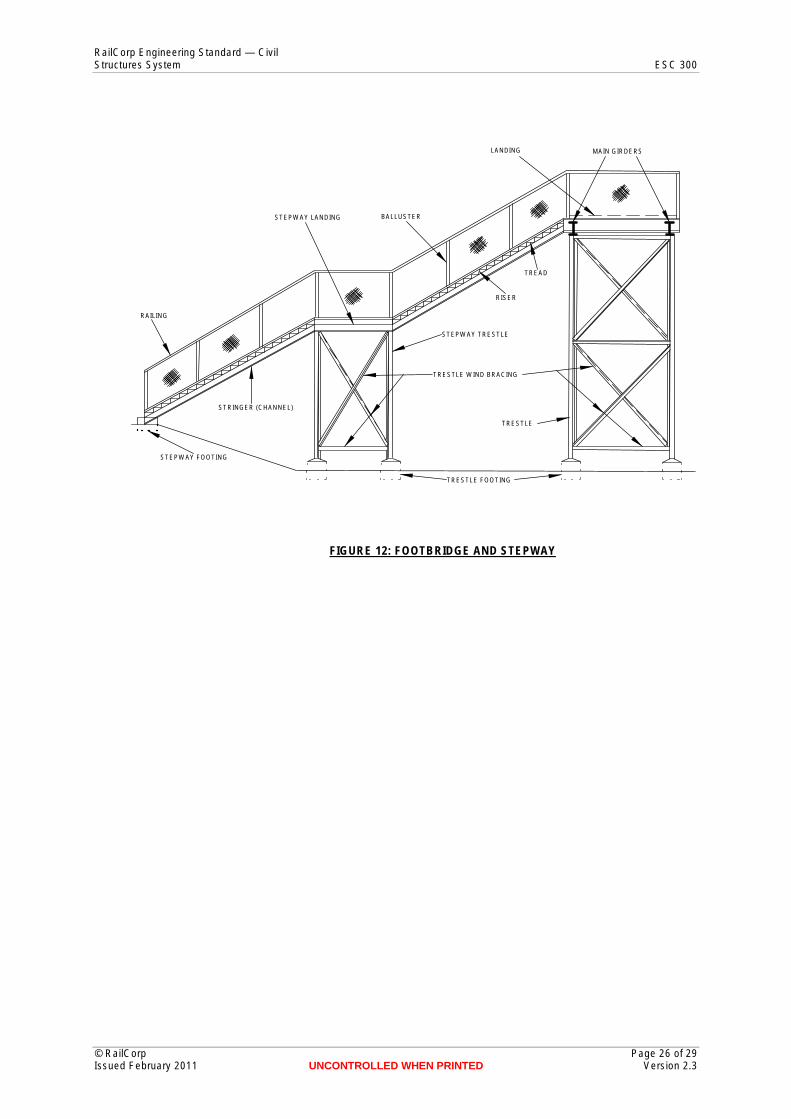
Figure 12: Footbridge and stepway
Figure 13: Rolled steel sections
© RailCorp Page 16 of 29 Issued February 2011 UNCONTROLLED WHEN PRINTED Version 2.3

ENGINEERED BACKFILL
SCOUR PROTECTION
STEEL GIRDERS
HEADSTOCKS
PIERS
PILECAPS
PILES
HANDRAIL & WALKWAY
WINGWALL
ABUTMENT 2 ABUTMENT 1
ELEVATION
RailCorp Engineering Standard — Civil Structures System ESC 300
WALKWAY
TRANSOM
GIRDERS
GRATING
HANDRAIL
TRANSOM BOLT
ZINC STRIP
RAIL GUARDRAIL
SINGLE TRACK - DECK CROSS SECTION
FIGURE 1: TRANSOM TOP UNDERBRIDGE
© RailCorp Page 17 of 29 Issued February 2011 UNCONTROLLED WHEN PRINTED Version 2.3

HANDRAILING
GIRDERS
ABUTMENT ABUTMENT HEADSTOCKS
PIERS
PILE CAPS
PILES
GEOGRID REINFORCED FILL
SCOUR PROTECTION
ELEVATION
RailCorp Engineering Standard — Civil Structures System ESC 300
CL CLDN TRACK UP TRACK
KERB
TIE BARS
WALKWAY
EXTERNAL INTERNAL EXTERNAL GIRDER GIRDERS GIRDER
MULTIPLE TRACK - DECK CROSS SECTION
FIGURE 2: BALLAST TOP UNDERBRIDGE
© RailCorp Page 18 of 29 Issued February 2011 UNCONTROLLED WHEN PRINTED Version 2.3

BALLAST
HANDRAIL
DECK SLAB DECK SLAB
BOX GIRDER BOX GIRDER
WALKWAY
FIGURE 3: CONCRETE BOX GIRDER
MULTIPLE TRACK
HANDRAILING AND WALKWAY SPANDRELL WALL
ARCH
PIERS ABUTMENT
FIGURE 4: MASONRY ARCH BRIDGE
LINK SLAB CROWN UNIT
WINGWALL
BASE AND APRON SLAB
RailCorp Engineering Standard — Civil Structures System ESC 300
FIGURE 5: CONCRETE BOX CULVERT
© RailCorp Page 19 of 29 Issued February 2011 UNCONTROLLED WHEN PRINTED Version 2.3

TRANSOM BOLT RAIL
GUARD RAIL
WEB STIFFENER
BROAD FLANGE BEAM
BED PLATE
CHANNEL DIAPHRAGM (C 380 X 100)
H.D. BOLT HOLES
WIND BRACING
BEARING PLATE
RailCorp Engineering Standard — Civil Structures System ESC 300
FIGURE 6: BROAD FLANGE BEAM (BFB) SPAN
© RailCorp Page 20 of 29 Issued February 2011 UNCONTROLLED WHEN PRINTED Version 2.3

70 70 TRANSOM PACKER
TRANSOM
STIFFENER
CONTINUOUS ZINC STRIP 670 WIDE
TRANSOM BOLT
WIND BRACE
DIAPHRAGM
TYPICAL SECTION ORIGINAL DESIGN
TRANSOM TRANSOM PACKER 70
70
STIFFENER BOLTED TO BOTTOM FLANGE
TYPICAL SECTION MODIFIED DESIGN
TRANSOM BOLT
RailCorp Engineering Standard — Civil Structures System ESC 300
FIGURE 7: PLATE WEB GIRDER (WELDED) DECK SPAN
© RailCorp Page 21 of 29 Issued February 2011 UNCONTROLLED WHEN PRINTED Version 2.3
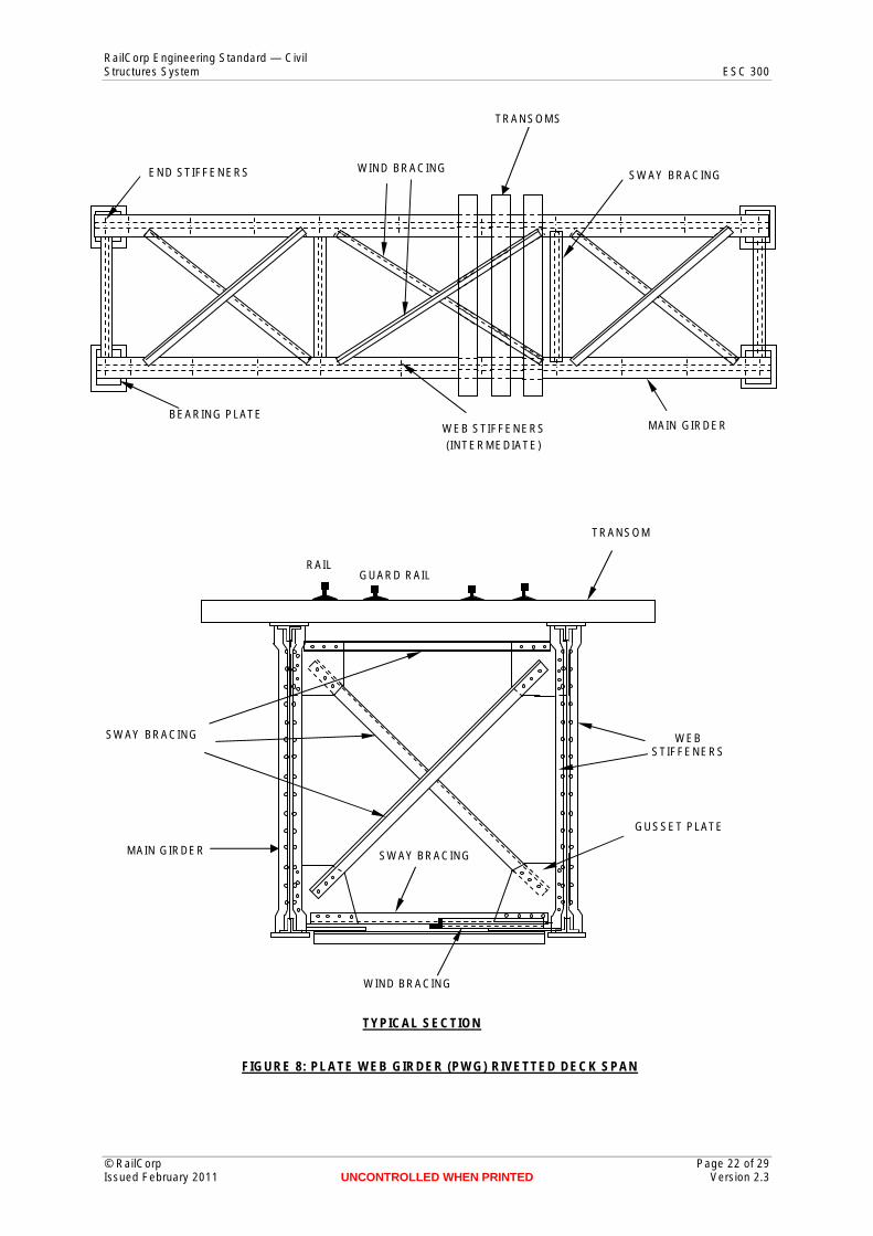
TRANSOMS
END STIFFENERS WIND BRACING SWAY BRACING
BEARING PLATE WEB STIFFENERS MAIN GIRDER
(INTERMEDIATE)
TRANSOM
WIND BRACING
SWAY BRACING
SWAY BRACING
RAIL GUARD RAIL
MAIN GIRDER
WEB STIFFENERS
GUSSET PLATE
TYPICAL SECTION
RailCorp Engineering Standard — Civil Structures System ESC 300
FIGURE 8: PLATE WEB GIRDER (PWG) RIVETTED DECK SPAN
© RailCorp Page 22 of 29 Issued February 2011 UNCONTROLLED WHEN PRINTED Version 2.3

STRINGERS CROSS GIRDER
GUSSET PLATE MAIN GIRDER
CROSS GIRDER
WIND BRACE
GUSSET PLATE
PLAN
STRINGER GIRDER (RSJ)
WEB STIFFENER
CLEAT
CROSS GIRDER
SECTION
RailCorp Engineering Standard — Civil Structures System ESC 300
FIGURE 9: PLATE WEB GIRDER (PWG) RIVETTED THROUGH SPAN
© RailCorp Page 23 of 29 Issued February 2011 UNCONTROLLED WHEN PRINTED Version 2.3

TOP CHORD
TRUSS SWAY BRACING
TOP CHORD WIND BRACING
PORTAL BRACING
END POST
VERTICAL WEB MEMBER
DIAGONAL WEB MEMBER
BOTTOM CHORD
BOTTOM CHORD WIND BRACING
(STRINGERS AND THEIR BRACING NOT SHOWN)
PORTAL BRACING END POST
STRINGER GIRDER
STRINGER SWAY BRACING
BOTTOM CHORD
CROSS GIRDER
BOTTOM CHORD WIND BRACING END VIEW STRINGER WIND BRACING
(CONNECTS FLANGES OF STRINGERS)
RailCorp Engineering Standard — Civil Structures System ESC 300
FIGURE 10: TRUSS GIRDER THROUGH SPAN
© RailCorp Page 24 of 29 Issued February 2011 UNCONTROLLED WHEN PRINTED Version 2.3

(RSJ)
A
PARAPET
No 1 ABUTMENT
No. 1 TRESTLE
MAIN GIRDERS
HEADSTOCK No 2 TRESTLE
DOWN TRACK UP TRACK
BRICKWORK
CONCRETE
TRESTLE FOOTING
A
No 2 ABUTMENT
PARAPET
No. 2 No. 3 No.4 No. 1
No. 5
MAIN GIRDERS
TRESTLE
TRESTLE SWAY BRACING
No. ABU
SYDNEY
RailCorp Engineering Standard — Civil Structures System ESC 300
FIGURE 11: STEEL OVERBRIDGE JACK ARCH SPAN
© RailCorp Page 25 of 29 Issued February 2011 UNCONTROLLED WHEN PRINTED Version 2.3
RailCorp Engineering Standard — Civil Structures System ESC 300
© RailCorp Page 26 of 29 Issued February 2011 UNCONTROLLED WHEN PRINTED Version 2.3
LANDING MAIN GIRDERS
BALLUSTER STEPWAY LANDING
RAILING
STEPWAY FOOTING
STRINGER (CHANNEL)
TREAD
RISER
STEPWAY TRESTLE
TRESTLE WIND BRACING
TRESTLE
TRESTLE FOOTING
FIGURE 12: FOOTBRIDGE AND STEPWAY

FLANGE
FILLET WEB
ALL 300
NO MARKINGS
R.S.J B.F.B ROLLED STEEL JOIST (BROAD FLANGE BEAM) (TAPERED FLANGE BEAM)
TOE
MARKED 'B.H.P'
HEEL
FILLET
U.B. U.C. UNIVERSAL BEAM UNIVERSAL COLUMN ANGLE
CHANNEL TEE Z BAR
RailCorp Engineering Standard — Civil Structures System ESC 300
FIGURE 13: ROLLED STEEL SECTIONS
© RailCorp Page 27 of 29 Issued February 2011 UNCONTROLLED WHEN PRINTED Version 2.3

RailCorp Engineering Standard — Civil Structures System ESC 300
Appendix D Withdrawn Standard Plans
PLAN NUMBER TITLE
SP 423 Ash Stop for Siding F1248 Blocks, Stop 94-195 Buffer Stop, Standard 204-88 Buffer Stop, Standard for Terminal Roads SP 469 Buffer Stop, Standard 1957
93-20 Cables, Under Tracks, Concreting of carrier pipes F 1677 Cattle Stop, renewal of timber abutments in concrete 190-211 Cattle Stop Standard Movable ST 171 Concrete Data Sheet ST 58 Crossing, Alignment of Road Crossings 1933 F 2775 Crossing, Water Main, from 4" to 20" diameter SS 407 Crossing, Under Tracks, Reinforced concrete encasing 84-143 Culverts, Multiple Reinforced Concrete 84-144 Culverts, Multiple 3’ 0” Reinforced Concrete SS 400 Culvert, Concrete, 16" Open top SS 410 Culverts, Single Reinforced Concrete, Old rail type SS 411 Culverts, Multiple Reinforced Concrete, Old rail type SS 412 Culvert, Reinforced Concrete, Standard 2’ 0” x 2’ 0” SS 413 Culverts, Reinforced Concrete, Standard 3' 0" SS 414 Culverts, Standard Reinforced Concrete SS 424 Culvert, Concrete Pipe ST 73 Culverts, Standard Brick
1953-46, 874 Derail STD - Hand Operated ST 12C Draining Method, Soft Places in Road Bed ST 12D Draining Method, Soft Places in Road Bed ST 12F Drainage on Soft Places Under Track SD 400 Drainage of Tracks - Sumps SD 401 Drainage of Tracks - Sumps, Surface SD 402 Drainage of Tracks - Spall Drains SD 404 Drains for Roadways (Precast Box Drains)
204A-152 End Loading Ramp (STD) Concrete, Type B 205A-19 End Loading Ramp (STD) Concrete, Type A SS 404 Extension Nut, Holding Down Bolts
ST 55 Fence, Dropper SG 404 Fence, Standard, Man Proof SG 409A Fences, Typical, General Arrangement SG 410 Fences, Typical, Details SG 415 Fence, Fettlers SG 423A Fence, Standard SG 424 Fences, Wing for Use at Level Crossings
95-121 Gates, Tubular, Methods for Strengthening
© RailCorp Page 28 of 29 Issued February 2011 UNCONTROLLED WHEN PRINTED Version 2.3

RailCorp Engineering Standard — Civil Structures System ESC 300
PLAN NUMBER TITLE ST 53A Gates, Pipe, STD 204A-57 Guard Rail, Level Crossings 1977-48, 802 Guard Rail, Level Crossings ST 71 Guard Rails, STD for Opening ST 71A Guard Rails, STD for Openings on Curves
F 1414 Hangers for Painting Bridges, Standard Adjustable SG 405 Level Crossing Signs STD ST 56 Level Crossing Signs STD SP 412 Level Crossing Signs STD SP 514A Loading Bank, STD 3’ 4” and 5’ 10” High
154-126 Platform, Old rail with concrete deck 184-51 Platform Walls, Standard, Cantilever Type ST 6 Platform Walls, Standard, Brick ST 7 Platform Walls, Standard, Concrete ST 8 Platforms, Standard, Precast Concrete Units
SG 425 Sign for Unattended Level Crossings ST 80 Steel Openings, Standard 6’, 8’ 10’ and 14’ 95-120 Stock unloading Ramp, Old Sleeper Type 726-40, 984 Stock unloading Ramp, Old Sleeper Type, Single
F 577 Timber Openings, 14’ 0”, Method of Strengthening H 971 Timber Openings, 4’ 0”, Concrete piers & abutments H 972 Timber Openings, 6’ 0”, Replacement of timber abutment H 973 Timber Openings, 4’ 0”, Replacement of timber abutment SS 420B Timber Openings, Renewal of piles, Method of repair SS 421 Timber Openings, 4’ 0”, Concrete piers, Low trestles SS 422 Timber Openings, 6’ 0”, Concrete piers, Low trestles SS 425 Timber Openings, Standard protection for ends of tip spans 99-140 Timber Openings, 14'-0", Concrete Abutments & Piers ST 83 Timber Openings, 10’ 6”, Concrete piers, Low trestles SP 495 Timber Take-off (STD Portable) ST 95A Timber Underbridges, Method of fixing transoms SS 432 Track Slab for Siding, Type 1 SS 433 Track Slab for Siding, Type 2 ST 94B Transom bolts (STD) and Ballast Logs ST 12E Treating Bad Formation - Method of ST 75 Tunnels, Standard
SG 407 Walkways between platforms, portable timber SG 428 Walkway, Pedestrian, STD movable 176B-18A Warning Sign STD, Type "G" for LX gates
© RailCorp Page 29 of 29 Issued February 2011 UNCONTROLLED WHEN PRINTED Version 2.3