esb national code of practice
95
Transcript of esb national code of practice


National Code of Practice at Customer Interface Modification Log Date of modification Page
NumberNature of modification
09-07-2008 50 Meter enclosure size modified to 600x400x200 added ref to pVII (b)
Page I
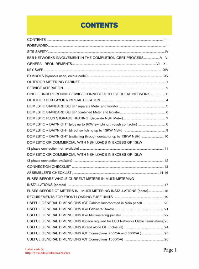
CONTENTS ..................................................................................................................................................I - II
FOREWORD....................................................................................................................................................III
SITE SAFETY....................................................................................................................................................IV
ESB NETWORKS INVOLVEMENT IN THE COMPLETION CERT PROCESS ....................V - VI
GENERAL REQUIREMENTS..........................................................................................................VII - XIII
KEY SAFE ......................................................................................................................................................XIV
SYMBOLS (symbols used, colour code.) ................................................................................................XV
OUTDOOR METERING CABINET ............................................................................................................1
SERVICE ALTERATION ................................................................................................................................2
SINGLE UNDERGROUND SERVICE CONNECTED TO OVERHEAD NETWORK ....................3
OUTDOOR BOX LAYOUT/TYPICAL LOCATION ..................................................................................4
DOMESTIC STANDARD SETUP separate Meter and Isolator ............................................................5
DOMESTIC STANDARD SETUP combined Meter and Isolator..........................................................6
DOMESTIC PLUS STORAGE HEATING (Separate NSH Meter) ......................................................7
DOMESTIC – DAY/NIGHT (plus up to 8KW switching through contactor) ....................................8
DOMESTIC – DAY/NIGHT (direct switching up to 13KW NSH) ....................................................9
DOMESTIC – DAY/NIGHT (switching through contactor up to 13KW NSH) ............................10
DOMESTIC OR COMMERCIAL WITH NSH LOADS IN EXCESS OF 13kW
(3 phase connection not available) ..........................................................................................................11
DOMESTIC OR COMMERCIAL WITH NSH LOADS IN EXCESS OF 13kW
(3 phase connection available) ..................................................................................................................12
CONNECTION CHECKLIST ....................................................................................................................13
ASSEMBLER'S CHECKLIST ..............................................................................................................14-16
FUSES BEFORE WHOLE CURRENT METERS IN MULTI-METERING
INSTALLATIONS (photos) ..........................................................................................................................17
FUSES BEFORE CT METERS IN MULTI-METERING INSTALLATIONS (photo)....................18
REQUIREMENTS FOR FRONT LOADING FUSE UNITS ..............................................................19
USEFUL GENERAL DIMENSIONS (CT Cabinet Incorporated in Main panel)............................20
USEFUL GENERAL DIMENSIONS (For Cabinets/Boxes) ..............................................................21
USEFUL GENERAL DIMENSIONS (For Multimetering panels) ......................................................22
USEFUL GENERAL DIMENSIONS (Space required for ESB Networks Cable Terminations)23
USEFUL GENERAL DIMENSIONS (Stand alone CT Enclosure) ..................................................24
USEFUL GENERAL DIMENSIONS (CT Connections 250/5A and 600/5A ) ............................25
USEFUL GENERAL DIMENSIONS (CT Connections 1500/5A) ..................................................26
CCOONNTTEENNTTSS
Latest code @http://www.esb.ie/esbnetworks/ncp
Page IILatest code @http://www.esb.ie/esbnetworks/ncp
DOMESTIC PLUS NSH ..................................................................................................................27
APARTMENTS DAY/NIGHT ELECTRONIC METERING FROM 2008 ..............................28
RELAY CONTROL DIAGRAM (Not for new installations) ......................................................29
COMMERCIAL/INDUSTRIAL PLUS SEPARATE NSH (multi-customer whole current) 30
PARTICULAR TO APARTMENT/OFFICE BLOCKS..................................................................31
ESB Networks MAIN CONNECTION FUSED UP TO 300A (arrangement for one
customer bulk tariff) ............................................................................................................................32
ESB Networks MAIN CONNECTION FUSED UP TO 300A (one customer multi-tariff) ..........33
CONNECTION OVER 300 AMPS (direct connection from sub station) ......................................34
CONNECTION OVER 300 AMPS (One customer) ............................................................................35
CONNECTION OVER 300 AMPS (photo, typical ESB Networks cable termination ) ..............36
CONNECTION OVER 300 AMPS (multi-customer)............................................................................37
ARRANGEMENTS FOR FIRE FIGHTING CONNECTION ..............................................................38
FIRE FIGHTING SAFETY LABELS (warning labels) ..........................................................................39
ESB Networks MAIN CONNECTION OVER 300A (single customer, wall mounted) ................40
SHOPPING CENTRES AND COMMERCIAL/INDUSTRIAL UNITS (general) ..........................41
SHOPPING CENTRES or COMMERCIAL/INDUSTRIAL UNITS (Centralised metering) ......42
COMMERCIAL/INDUSTRIAL UNITS (Alternative method ................................................................43
GROUPS OF SHOPS/OFFICES (facing onto public roadway) ......................................................44
CONNECTION FOR TEMPORARY INSTALLATION ..........................................................................45
PETROL STATIONS......................................................................................................................................46
STAND-BY GENERATORS (Small connections - Manual Changeover) ........................................47
STAND-BY GENERATORS (larger connections - Auto changeover) ..............................................48
STAND-BY GENERATORS (multi customer) ........................................................................................49
AGRICULTURAL/HORTICULTURAL PREMISES (general)..............................................................50
REMOTE BUILDINGS ................................................................................................................................51
SPECIAL SITUATIONS (e.g. street furniture, Garda cameras/CCTV etc.) ..............................52-57
PUBLIC LIGHTING ................................................................................................................................58-62
REQUIREMENTS FOR CONNECTION AT MEDIUM VOLTAGE (MV) ................................63-69
ADDITIONAL USEFUL INFORMATION ................................................................................................70
SURFACE AND FLUSH MOUNTED METERING ENCLOSURE APPENDIX A-B
COMMERCIAL TEMPORARY SUPPLY APPENDIX C
MAIN OVERCURRENT DEVICE IN STANDARD METERING CABINET APPENDIX D
ESB NETWORKS CONTACT NUMBERS AND AREAS APPENDIX F-H
CCOONNTTEENNTTSS

Page IIILatest code @http://www.esb.ie/esbnetworks/ncp
This National Code of Practice for Customer Interface – 4th edition, 2008, replaces the3rd edition.
The purpose of this National Code of Practice for Customer Interface is to have onesingle interpretation of ESB Networks requirements.
It is a consensus document agreed between people involved in the electrical industryand ESB Networks.
Contractors Associations, Consulting Engineers, Switchboard Assembler's, ElectricalWholesalers, Distributors, Regulatory Bodies and ESB Networks staff made a verypositive contribution in the compiling of this Code.
It is important that everyone working at the ESB Networks/Customer Interface ordesigning electrical equipment for that interface fully understands the Code and worksto it.
Each ESB Networks local office will provide details of who should be contactedregarding queries, which may arise in the interpretation of this Code of Practice.
It is always essential to refer to the latest version of The National Code of practice athhttttpp::////wwwwww..eessbb..iiee//eessbbnneettwwoorrkkss//nnccpp
SCOPE
The National Code of Practice for Customer Interface relates to situations where aninterface exists between the customer and ESB Networks at 230/400 volts and/or MVexists.
The aim of the Code Book is to assist in achieving a single interpretation of therequirements for metering/connection.
ESB Networks are fully supportive of ETCI, CER and the regulatory bodies in theirefforts to improve safety and standards of electrical installations.
ESB Networks recognise the need for and the importance of testing and certification ofall electrical installations.
Completion certificates are required for all new installations and alterations or extensionsto all existing installations. (See “ESB Networks involvement in Completion CertificateProcess” on page V and Vl.)
FFOORREEWWOORRDD

Page IVLatest code @http://www.esb.ie/esbnetworks/ncp
•• BBee aawwaarree ooff yyoouurr wwoorrkkiinngg eennvviirroonnmmeenntt aanndd yyoouurr rreessppoonnssiibbiilliittiieessttoo yyoouurrsseellff aanndd ootthheerrss..
•• CCoonnttrraaccttoorrss,, BBuuiillddeerrss,, DDeevveellooppeerrss aanndd EESSBB NNeettwwoorrkkss mmuusstt mmeeeettaallll ssttaattuuttoorryy rreeqquuiirreemmeennttss iinn oorrddeerr tthhaatt ssiittee ccoonnddiittiioonnss aanndd ssiitteepprraaccttiicceess pprroovviiddee aa ssaaffee wwoorrkkiinngg eennvviirroonnmmeenntt..
•• EElleeccttrriiccaall CCoonnttrraaccttoorrss aanndd EESSBB NNeettwwoorrkkss ssttaaffff sshhoouulldd aallwwaayyss bbeeaalleerrtt ttoo tthhee ddaannggeerrss aanndd hhaazzaarrddss aassssoocciiaatteedd wwiitthh eelleeccttrriiccaall wwoorrkk..
•• PPaarrttiiccuullaarr aatttteennttiioonn iiss rreeqquuiirreedd wwhheenn aann iinnssttaallllaattiioonn iiss mmaaddee lliivveewwhheetthheerr oonn aa tteemmppoorraarryy oorr ppeerrmmaanneenntt bbaassiiss..
•• AAllwwaayyss mmaakkee ssuurree iiff yyoouu mmaakkee aann iinnssttaallllaattiioonn oorr ppaarrtt ooff aanniinnssttaallllaattiioonn ““lliivvee”” tthhaatt yyoouu hhaavvee nnoott ccrreeaatteedd aa ddaannggeerroouuss ssiittuuaattiioonnffoorr ssoommeeoonnee eellssee..
•• AAllwwaayyss cchheecckk ffoorr aabbsseennccee ooff vvoollttaaggee bbeeffoorree yyoouu wwoorrkk oonn aannyyiinnssttaallllaattiioonn..
RReemmeemmbbeerr tthhee FFiivvee EElleeccttrriiccaall SSaaffeettyyRRuulleess
11.. DDiissccoonnnneecctt CCoommpplleetteellyy22.. SSeeccuurree aaggaaiinnsstt RReeccoonnnneeccttiioonn33.. VVeerriiffyy tthhee iinnssttaallllaattiioonn iiss ““ddeeaadd””..44.. CCaarrrryy oouutt eeaarrtthhiinngg aanndd sshhoorrtt -- cciirrccuuiittiinngg((wwhheerree aapppprroopprriiaattee))..55.. PPrroovviiddee pprrootteeccttiioonn aaggaaiinnsstt aaddjjaacceenntt ““lliivvee”” ppaarrttss..
SSIITTEE SSAAFFEETTYY
Page VLatest code @http://www.esb.ie/esbnetworks/ncp
ESB Networks are not involved in, or responsible for, testing a customers electricalinstallation. To comply with current legislation a completion certificate is required for allnew electrical installations and some alterations to existing installations. This certificateis issued to the customer by the electrical contractor indicating that the installation isconstructed and tested to meet Electro Technical Council of Ireland's (ETCI)requirements.
TTHHEE CCEERRTTIIFFIICCAATTEE SSHHOOUULLDD OONNLLYY BBEE IISSSSUUEEDD AATT TTHHEE CCOOMMPPLLEETTEEDDSSTTAAGGEE OOFF TTHHEE EELLEECCTTRRIICCAALL WWOORRKK
The completion certificate is required to allow ESB Networks to proceed with their workfor the customer.
IItt iiss eesssseennttiiaall tthhaatt tthhee ccoorrrreecctt MMPPRRNN ((MMeetteerr PPooiinntt RReeffeerreennccee NNuummbbeerr))iiss rreeccoorrddeedd oonn tthhee cceerrttiiffiiccaattee aanndd tthhee aaddddrreessss ooff tthhee iinnssttaallllaattiioonn
mmaattcchheess tthhee MMPPRRNN aaddddrreessss..
This MPRN number is readily available on correspondence the customer receives fromESB Networks regarding their application for a new connection/ alterations/rewires etc.
ESB Networks require completion certificates, submitted through the regulatory body,for the following types of Electrical Work:
• All new installations/re-wires requiring connection to ESB Network
• All alterations to existing installations involving changes to the wiring between ESB Networks connection point/meter and the customer's distribution board.
• In multi-tenanted / multi-metered situations a completion certificate is required for each ESB Networks connection, i.e. one certificate per customer connection point.
• Where installations such as school signs, phone kiosks, bus shelters etc. are connected to ESB Networks network, a completion certificate is required for each connection at the interface.
• All Medium Voltage installations require a completion certificate (Note a declaration of fitness is also required by ESBN)
• A completion certificate is required before connection will be restored to aninstallation that has been disconnected for more than 6 months.
EESSBB NNEETTWWOORRKKSS IINNVVOOLLVVEEMMEENNTT IINN TTHHEE CCOOMMPPLLEETTIIOONN CCEERRTTIIFFIICCAATTEE PPRROOCCEESSSS
Page VILatest code @http://www.esb.ie/esbnetworks/ncp
IInn ssiittuuaattiioonnss rreeqquuiirriinngg cclloossee ccoo--ooppeerraattiioonn bbeettwweeeenn EESSBB NNeettwwoorrkkss aannddtthhee EElleeccttrriiccaall CCoonnttrraaccttoorr ee..gg.. WWoorrkk oouuttssiiddee nnoorrmmaall hhoouurrss,, TThheeffoolllloowwiinngg pprroocceedduurree iiss rreeqquuiirreedd::
• It is important to contact the local ESB Networks supervisor at an early stage in the planning of the work.
• The Customer should ensure that any payments required by ESB Networks have been paid. ( this will ensure that a service order is in existence.)
• The Electrical Contractor must contact the relevant regulatory body with the specific certificate number he/she intends to use to certify the finished work. The specific details required are: Certificate number, type, Customers correct MPRN and name and address,
• The Regulatory Body will record this initial information which will allow the ESB Networks service order for this work to be released.
• The Electrical Contractor should use the certificate reserved for the electrical work to record the test results after the electrical work is completed.
• Afterwards the fully completed certificate should be sent (without delay) to the relevant Regulatory Body.
AAnnyy ccoonnttrraaccttoorr wwoorrkkiinngg iinn cclloossee pprrooxxiimmiittyy ttoo lliivvee EESSBB NNeettwwoorrkkss sseeaalleeddeeqquuiippmmeenntt ((wwhheerree nnoo mmaaiinn iissoollaattoorr eexxiissttss)) sshhoouulldd ccoonnttaacctt tthhee llooccaallEESSBB NNeettwwoorrkkss ooffffiiccee iiff hhee//sshhee rreeqquuiirreess iissoollaattiioonn ooff tthhaatt eeqquuiippmmeenntt ttooaallllooww tthhee wwoorrkk ttoo pprroocceeeedd pprriioorr ttoo cceerrttiiffiiccaattiioonn..
EESSBB NNEETTWWOORRKKSS IINNVVOOLLVVEEMMEENNTT IINN TTHHEE CCOOMMPPLLEETTIIOONN CCEERRTTIIFFIICCAATTEE PPRROOCCEESSSS
Page VIILatest code @http://www.esb.ie/esbnetworks/ncp
11 CCOONNSSUULLTTAATTIIOONN WWIITTHH EESSBB NNeettwwoorrkkss OOFFFFIICCEE It is essential to consult with the local ESB Networks office at the planning stage of thefollowing projects: new premises, refurbishment of existing premises, major additions toexisting load. All essential information such as; site maps, architect’s drawings etc.should be submitted to ESB Networks to allow applications to be processed efficiently.
22 LLOOAADD TTHHRREESSHHOOLLDDSS((aa)) NNeeww IInnssttaallllaattiioonnss:: Single phase whole current meters will be used to measure loads up to 80A per phase.In general, three phase whole current meters will be used to measure loads over threephases up to 80A per phase. Current transformers with matching meters will be used tomeasure loads in excess of 80A per phase. Allowances for potential load growth shouldalways be made.
((bb)) EExxtteennssiioonnss//RReennoovvaattiioonnss ttoo EExxiissttiinngg MMeetteerriinngg:: Discuss with local ESB Networks Office beforehand, where, in certain circumstances,three phase whole current metering at 100A per phase may be considered. ESB Networks will connect and fit a main fuse unit for total loads within a building up to300A (200 kVA). ESB Networks will normally require a Substation for loads in excess of 300A (200kVA).Customer will supply and fit a main circuit breaker. New loads in excess of 500kVA willin general be supplied at medium voltage. NN..BB.. SSoommee llooaaddss ooff lleessss tthhaann 220000kkVVAAmmaayy rreeqquuiirree aa ssuubbssttaattiioonn iinn uurrbbaann llooccaattiioonnss ddeeppeennddiinngg oonn aavvaaiillaabbllee ccaappaacciittyy..
33 EENNCCLLOOSSUURREESS FFOORR MMEETTEERRIINNGG EEQQUUIIPPMMEENNTT((aa)) PPaarrttiiccuullaarr ttoo DDoommeessttiicc iinnssttaallllaattiioonnss..(i) ESBN equipment should only be fitted in the outdoor metering cabinet. The only
exception being where the customer’s main Isolation/over current device is fitted inthe cabinet. Where fitted, the device must be located at the bottom RHS of theenclosure (marked ** page 1) to allow future ESBN equipment modifications. NN..BB..sseeee EETTCCII EETT110011 rreeqquuiirreemmeennttss
(ii) Page 1 shows a typical outdoor Metering cabinet. This is the standard method fornew Metering.
(iii) Where it is clearly impossible to fit ESB Networks’ equipment into an accessibleoutdoor location, the ESBN Design office must be consulted at the planning stage,to determine the most suitable location.
(iv) Where indoor locations are permitted an enclosure shall be provided for ESBNetworks’ equipment. See page 21 for details on enclosures.
((bb)) WWhhoollee CCuurrrreenntt MMeetteerriinngg:: Whole current meters and ESB Networks equipmentare installed by ESB Networks in an enclosure supplied and fitted by the customer. (Seepage 21).
GGEENNEERRAALL RREEQQUUIIRREEMMEENNTTSS
Page VIIILatest code @http://www.esb.ie/esbnetworks/ncp
Whole current meter enclosures shall have a (vertically) hinged cover or visor andstandard 8mm Triangular lock.
ESB Networks metering equipment shall be fitted in indoor situations at a height fromfloor level no lower than 600 mm to the bottom of the lowest meter and no higher than2000 mm to top of highest meter.
((cc)) CCuurrrreenntt TTrraannssffoorrmmeerr ((CCTT)) MMeetteerriinngg:: Customer shall supply and fit a sealableenclosure to accept ESB Networks’ CTs. Where a main switchboard is installed thisenclosure should be within the switchboard. C.T. Meter Cabinets (supplied and fittedby ESB Networks) are installed on a wall adjacent to the main switchboard. IInn ssoommeessiittuuaattiioonnss ccoonnssiiddeerraattiioonn wwiillll bbee ggiivveenn ttoo iinnccoorrppoorraattee EESSBB NNeettwwoorrkkss CCTT MMeetteerrssiinnttoo tthhee mmaaiinn SSwwiittcchhbbooaarrdd.. SSeeee ppaaggee 2200.. DDiissccuussss wwiitthh LLooccaall EESSBB NNeettwwoorrkkssssttaaffff aatt tthhee ddeessiiggnn ssttaaggee ooff tthhee SSwwiittcchhbbooaarrdd..
NNoottee:: WWhheerree tthhee CCTT EEnncclloossuurree iiss ooff aa mmeettaall ttyyppee tthhee ccoovveerr sshhaallll bbee hhiinnggeedd((vveerrttiiccaallllyy)) aass wweellll aass sseeaallaabbllee..
Where the CTs are on the ESB Networks side of the customers main disconnectingdevice, the enclosure shall offer protection against contact with live parts by the ingressof tools, wires or any other foreign body. (IP 3X min.) (Note: For wall mounted MeterCabinets, CT Secondary cable run shall not exceed 15 Metres and shall be accessable.)SSeeee 55.
44 RREEQQUUIIRREEMMEENNTTSS FFOORR MMEETTEERRIINNGG EENNCCLLOOSSUURREESS.. UUSSEEDD OOUUTTDDOOOORRSS
((aa)) CCeennttrraalliisseedd MMuullttii--CCuussttoommeerr mmeetteerriinngg..
OOuuttddoooorr llooccaattiioonnss aarree nnoott rreeccoommmmeennddeedd ffoorr cceennttrraalliisseedd mmuullttii--ccuussttoommeerrmmeetteerriinngg.. Vandalism, interference, and environmental conditions increase thelikelihood of damage corrosion etc.
NN..BB.. AAllll llooccaattiioonnss ootthheerr tthhaann mmaaiinn sswwiittcchh rroooommss aanndd ssttaannddaarrdd iinntteerrnnaallmmeetteerriinngg llooccaattiioonnss aarree ccoonnssiiddeerreedd ttoo bbee oouuttddoooorrss..
Because of these considerations and where it has been agreed with ESBN at theplanning stage to locate centralised multi-customer metering outdoors, the followingminimum requirements described in (i) and (ii) shall apply :
(i) The switchboard housing the metering equipment shall be manufactured frompolyester or other suitable non conductive material. A minimum rating of IP44 shallapply, subject to the environmental influences in the location selected. Theswitchboard internal construction shall comply with the standards required for normallocations.
(ii) In addition all switchboards shall be protected against vandalism/interference byone of the following methods described in (iii) and (iv) :
(iii) The switchboard shall be installed in a concrete structure that is completelyweatherproof e.g. Where installed on the outside wall of a building it may comprise of
GGEENNEERRAALL RREEQQUUIIRREEMMEENNTTSS
Page IXLatest code @http://www.esb.ie/esbnetworks/ncp
two wing walls constructed at either end of the switchboard with a securely constructedroof to provide a weatherproof enclosure. Adequate lighting shall be provided.
The doors and door frame of the structure shall be the full width of the switchboard andshall be manufactured from high grade steel which shall have a minimum thickness of3mm (door) and all parts shall be treated with hot dip galvanising to EN ISO 1461. Inaddition the requirements listed at (v) below shall also apply.
(iv) The switchboard shall be installed in a unit manufactured from high grade sheet steelwhich shall have a minimum thickness of 3mm and all parts shall be treated with hot dipgalvanising to EN ISO 1461. In addition the requirements listed at (v) below shall alsoapply.
(v) Enclosures must incorporate sufficient internal ventilation to prevent the formation ofcondensation but without reducing the degree of protection required. All hinges shallopen a minimum of 180 degrees, door stays shall be provided where necessary. Allbelow ground parts shall have heavy duty corrosion protection. Consideration shall begiven to the risk of corrosion (as above), dust, vibration, and impacts, and adequatemeasures shall be taken to minimise these risks. All external doors shall be fitted withvandal proof locks to prevent unauthorised entry. The locking devices shall bemanufactured from high grade non corrosive metal. A keysafe (see page XIV) shall befitted to the enclosure, the keysafe is supplied by ESBN as part of the agreed design ofthe electricity services.
((bb)) SSppeecciiffiicc rreeqquuiirreemmeennttss ffoorr ssiinnggllee ccuussttoommeerr nnoonn--ddoommeessttiicc oouuttddoooorreenncclloossuurreess.
A minimum rating of IP44 shall apply subject to the environmental influences in thelocation selected. In a horticultural environment, IP55 is the minimum required.
In order to maintain the stability and integrity of enclosures used to house ESB Networksequipment in outdoor locations, the following minimum specifications shall apply.
WWhheerree eenncclloossuurreess aarree mmaannuuffaaccttuurreedd ffrroomm ffeerrrroouuss mmaatteerriiaallss,, tthhee eenncclloossuurreesssshhaallll bbee mmaannuuffaaccttuurreedd ffrroomm hhiigghh ggrraaddee sshheeeett sstteeeell wwhhiicchh sshhaallll hhaavvee aammiinniimmuumm tthhiicckknneessss ooff 33mmmm.. aanndd aallll ppaarrttss sshhaallll bbee ttrreeaatteedd wwiitthh hhoott ddiippggaallvvaanniissiinngg ttoo EENN IISSOO 11446611..
All hinges shall open vertically a minimum of 180 degrees, door stays shall be providedwhere necessary. All below ground parts shall have heavy duty corrosion protection.Consideration shall be given to the risk of condensation, dust vibration and impacts andadequate measures be taken to minimise these risks.
Where required, these units shall be fitted with vandal proof locks to preventunauthorised entry. The locking device shall be manufactured from high grade noncorrosive metal.
GGEENNEERRAALL RREEQQUUIIRREEMMEENNTTSS
Page XLatest code @http://www.esb.ie/esbnetworks/ncp
Where vandal proof locks are specified, a keysafe (see page XlV) shall be fitted to theunit, the keysafe is supplied by ESB Networks as part of the design of the electricityservices.
55 PPRROOTTEECCTTIIOONN FFOORR SSEECCOONNDDAARRYY CCAABBLLEESS FFRROOMM EESSBB NNeettwwoorrkkssMMEETTEERRIINNGG CCTTSS WWIITTHHIINN MMAAIINN SSWWIITTCCHHBBOOAARRDD
Trunking or conduit (min. 75 mm per set of CTs with draw wire) to protect secondarycables shall be provided by the Customer within the main switch board. This should beof metal, rigid plastic or similar and shall be accessable throughout it’s route.
Metal trunking of adequate size (MIN. 100mm) shall be provided from the switchboardto the CT metering cabinet AND MUST BE SEALABLE. See paragraph 9 r.e. ESBNetworks seals
66 AACCCCEESSSS TTOO MMEETTEERRIINNGG EEQQUUIIPPMMEENNTT
ESB Networks meters should be grouped in one easily accessible location(Centralised). Where access to metering has to be restricted, a Keysafe is required seepage Xll paragraph 17 for further details. ESB Networks whole current meters and CTsshould be located in one section of a Main Switchboard to allow for regular testing andinspection. Each set of CTs should be physically separated to allow them be workedon individually. The phases and neutral cores for each account must be terminatedwithin the CT chamber. A separate neutral bar shall be provided adjacent to each set ofCTs. Access to ESB Networks equipment must be available at all times. AAlllleenncclloossuurreess uusseedd ffoorr EESSBB NNeettwwoorrkkss mmeetteerrss sshhaallll hhaavvee aa ssttaannddaarrdd 88mmmmttrriiaanngguullaarr lloocckk ffiitttteedd.. AA cclleeaarr ssppaaccee ooff aatt lleeaasstt 11..22mm mmuusstt bbee lleefftt iinn ffrroonntt ooffEESSBB NNeettwwoorrkkss eeqquuiippmmeenntt..
77 UUNNAACCCCEEPPTTAABBLLEE LLOOCCAATTIIOONNSS FFOORR EESSBB NNeettwwoorrkkss MMAAIINN FFUUSSEESS AANNDDMMEETTEERRSS
ESB Networks main fuses and Meters shall not be installed in: Toilets, cellars, boilerhouses, fuel stores, storage cupboards, underneath wooden stairs or any location liableto dust, dampness, heat, vibration or any location having a corrosive atmosphere. Anylocation likely to be blocked by machinery, goods, furniture, or liable to cause accidentsis not permitted.
88 CCUUSSTTOOMMEERR MMAATTEERRIIAALLSS
The customer shall provide: all trunking, cables and connectors beyond the ESBNetworks main cable terminations. Load cables for connection to ESB Networks mainfuse unit, whole current meters or CTs to be stranded copper conductor or multi-stranded flexible copper conductor. Where multi-stranded cables are used they must befitted with appropriate ferrules or lugs.
GGEENNEERRAALL RREEQQUUIIRREEMMEENNTTSS

Page XILatest code @http://www.esb.ie/esbnetworks/ncp
99 EESSBB NNeettwwoorrkkss SSEEAALLSS
All access to unmetered enclosures, unmetered fuses, C.T. enclosures, secondarywiring and busbar chambers and all other possible points of access to unmeteredconnections shall be made inaccessible by means of an effective sealing system fittedby the manufacturer which will be sealed by ESB Networks. Seals should be visible forinspection at all times.
Note: Sealing holes drilled in cover which allow sealing wire enter the enclosure areunacceptable.
NNOOTTEE TTOO CCOONNTTRRAACCTTOORRSS RREEGGAARRDDIINNGG EESSBB NNeettwwoorrkkss SSEEAALLSS
EElleeccttrriiccaall ccoonnttrraaccttoorrss aarree rreemmiinnddeedd tthhaatt iitt iiss aann ooffffeennccee uunnddeerr tthhee ““((EEnneerrggyy))MMiisscceellllaanneeoouuss PPrroovviissiioonnss aacctt 11999955””,, ttoo bbrreeaakk EESSBB NNeettwwoorrkkss sseeaallss oorr ttooiinntteerrffeerree wwiitthh EESSBB NNeettwwoorrkkss eeqquuiippmmeenntt..
(1) If you find ESB Networks seals are broken or missing, report to ESB NetworksBEFORE YOU START WORK.
(2) Sealing, and the removal of all seals shall be undertaken by ESB Networks staffonly.
(3) ESB Networks seal numbers are recorded for each installation. Under nocircumstances interfere with them.
(4) Do not work on, or move ESB Networks equipment.
1100 LLAABBEELLLLIINNGG
Metering equipment shall be labelled ‘ESB Networks Whole Current meters.’ or ‘ESBNetworks CTs etc. Unmetered equipment should be clearly labelled “ESB Networks’.Labels must be of permanent and durable material. It is important that the electricalcontractor have them in place before connection.
A fire fighting connection taken from the live side of the main circuit breaker should besuitably labelled, and clearly visible to a person operating the main breaker. Labels shallbe fitted onto the fixed sections of a switchboard so as to eliminate the potential dangerwhere labelled doors/covers are interchangeable. (See page 39 for details)
In Multi-Metering installations a permanent label is required for the relevantApartment/Unit number, the Fuse before the Meter, the Meter and the outgoingswitchfuse/MCB. In Relay installations all control wiring shall be permanently labelled.These labels shall be fitted at the meter, the relays and the outgoing switchfuse/MCBbefore connection..
GGEENNEERRAALL RREEQQUUIIRREEMMEENNTTSS
Page XIILatest code @http://www.esb.ie/esbnetworks/ncp
GGEENNEERRAALL RREEQQUUIIRREEMMEENNTTSS
1111 TTAARRIIFFFFSS
Circuits for separately metered tariffs require electrical and physical segregation. (i.e.barriers) Providing this is satisfied they may be catered for side by side in the sameenclosure. NOTE: The customer or consultant acting on customer’s behalf shouldensure the correct tariff applies to the installation.
1122 SSWWIITTCCHHBBOOAARRDD AADDAAPPTTAABBIILLIITTYY
Switchboards being designed for speculative developments should make provision forthe various likely metering permutations to avoid costly alterations at the Connectionstage.
1133 MMUULLTTII--CCUUSSTTOOMMEERR PPRREEMMIISSEESS
For Connections up to 200kVA, the specified fuse units (pages 17-18) shall be suppliedand fitted by the customer before ESB Networks whole current meters and ESBNetworks metering current transformers (CTs). Above 200kVA the customer’s circuitbreaker is fitted before the CTs. All meters and metering equipment for each customershall be located at one central point, normally at the termination of ESB Networksconnection cable. In all new indoor installations suitable enclosures shall be providedto accept ESB Networks’ equipment.
FFuusseess ffoorr WWhhoollee CCuurrrreenntt MMeetteerriinngg aarree ssuupppplliieedd bbyy EESSBB NNeettwwoorrkkss
1144 BBUUSSBBAARRSS
If more than two connections are required at the main isolator, then a Busbar chamberis required.
1155 MMAAIINN PPRROOTTEECCTTIIVVEE CCOONNDDUUCCTTOORR CCOONNNNEECCTTIIOONN ((NNEEUUTTRRAALLIISSIINNGG))
The customer’s Main Protective Conductor is connected to the ESB Networks neutralat the Main Connection point in a TNCS system. NN..BB.. CCuussttoommeerr’’ss mmaaiinn eeaarrtthhtteerrmmiinnaall mmuusstt nnoott bbee wwiitthhiinn EESSBB NNeettwwoorrkkss’’ sseeaalleedd eenncclloossuurree..
1166 MMAAIINN CCOONNNNEECCTTIIOONN PPOOIINNTT
ESB Network’s responsibility extends up to customers Main Connection point: TheCustomer / Customers representative has responsibility for the electrical installationfrom that Main Connection point. The Main connection point is normally:
IInn MMaajjoorr IInnssttaallllaattiioonnss::
(a) At ESB Networks main fuses
Or
(b) On Incoming side of customer’s main circuit breaker

Page XIIILatest code @http://www.esb.ie/esbnetworks/ncp
GGEENNEERRAALL RREEQQUUIIRREEMMEENNTTSS
IInn ootthheerr iinnssttaallllaattiioonnss::
(a) At connection point of customer’s tails.
Or
(b) On Customer’s side of ESB Networks isolator
IInn iinnddoooorr llooccaattiioonnss wwhheerree EESSBB NNeettwwoorrkkss MMaaiinn FFuussee UUnniitt iiss ffiitttteedd iitt sshhaallll bbeellooccaatteedd cclloossee ttoo aann eexxtteerrnnaall ddoooorr ((ii..ee.. wwiitthhiinn 22mmttss))..
1177 AACCCCEESSSS TTOO EESSBB NNeettwwoorrkkss EEQQUUIIPPMMEENNTT OONN CCUUSSTTOOMMEERR’’SS PPRREEMMIISSEESS::
Specific arrangements may have to be made for particular premises using key safeswhich are available from ESB Networks. Contact local ESB Networks office forinformation. (Key safe information - See page XlV)
1188 RREEMMOOTTEE RREEAADDIINNGG OOFF MMEETTEERRIINNGG EEQQUUIIPPMMEENNTT::
AAllll CCoonnnneeccttiioonnss aatt 220000kkVVAA aanndd aabboovvee aarree rreeaadd rreemmootteellyy uussiinngg GGSSMMeeqquuiippmmeenntt..
For Quarter Hourly (QH) metering, adequate GSM/GPRS coverage is required at thechosen metering position to facilitate remote meter reading. If GSM signal strength isinadequate, provision shall be made by customer/contractor for the installation ofnecessary extra cabling and equipment to a suitable alternative antenna location.Alternatively customer/contractor may supply, at their own expense, a dedicated PSTNline for meter reading.
1199 CCUUSSTTOOMMEERR SSWWIITTCCHHIINNGG SSIIGGNNAALLSS::
Where ESBN provide a switching signal to customer’s equipment, e.g. contactor coil forNSH, the maximum permissable current shall be ≤ 80mA.

Page XIVLatest code @http://www.esb.ie/esbnetworks/ncp
KKeeyy SSaaffee
130mm
130m
m
102
mm
103mm
• Installed flush with wall to a depth of 103mm• Available from Local ESB Networks Depot.• For full specification, refer to current information from ESB Networks• Keysafe codes: Base: 911551 Cover plate: 911552

Page XVLatest code @http://www.esb.ie/esbnetworks/ncp
SSYYMMBBOOLLSS UUSSEEDD TTHHRROOUUGGHHOOUUTT TTHHIISS PPUUBBLLIICCAATTIIOONN
M M
COLOUR CODING USED THROUGHOUT BOOK
SUPPLIED BY ESB NETWORKS SUPPLIED BY CUSTOMER
ESB METERESB
TIMESWITCHESB ISOLATOR
METERSPECIAL ESB
ISOLATOR
CURRENT TRANSFORMER
3 PHASE 80 AMP
ESB CUTOUT
3 PHASE300 AMP
1 PHASE 80 AMP
ESB CUTOUTESB CUTOUT
Rela
y
FUSE ISOLATOR RELAYMAIN CIRCUIT
BREAKERSWITCHFUSE/MCB

ESB NetworksEquipment fitted inoutside meter box.
CustomerTails entry
point
Note: Meter cabinet must comply with ESB Networks Specifications
Flange of cabinet to be water sealed and polythene damp proof course to be fitted by builder
Customer Meter tails to enter at the bottom rightof the Meter cabinet. See notes below.
25mm
Fixing Spikes
50mm Dia. red electric cable duct, projecting 25mm inside the meter cabinet.
Water drain hole in the lowest sect ion of the pipe.
10mm draw-in rope (free of knots) to draw ESB Networks cable.
Hockey stick for service cable
Depth600mm
1.2m
Max
. 1M
min
.Fr
om fi
nish
ed g
roun
d le
vel
entry pointESB Networks
Connection
*
• To Comfortably accept the above cabinet, builders should provide an opening of 606mm(h) x 402 (w) x 155 (d)
• Where applicable, ensure that door hangs so as to allow latch to fall into closed position• For ESB Networks O/H connection situation see Sketch/photograph on pages 3/4 and/orcontact local ESB Networks office before fitting box
• The meter cabinet must be directly accessible from the main entrance driveway. Aposition on the house wall facing the driveway, or within 2m of either corner of this wall isnormally acceptable subject to proper access.
•• EEaacchh oouuttssiiddee bbooxx mmuusstt hhaavvee iiddeennttiiffiiccaattiioonn ttoo aassssoocciiaattee iitt wwiitthh aa ppaarrttiiccuullaarriinnssttaallllaattiioonn//aaddddrreessss,, tthhiiss II..DD.. sshhoouulldd bbee iinn ppllaaccee aatt sseerrvviiccee iinnssttaallllaattiioonn ssttaaggee..SSeeee pphhoottoo 11 ppaaggee 44 ffoorr ccoorrrreecctt eennttrryy ppooiinnttss..
Typical method of installation of outdoor Meter Cabinet
Page 1Latest code @http://www.esb.ie/esbnetworks/ncp
OOUUTTDDOOOORR MMEETTEERRIINNGG CCAABBIINNEETT
Page 2Latest code @http://www.esb.ie/esbnetworks/ncp
External Meter Cabinet
CR
OS
S S
EC
TIO
N V
IEW
New Service
New inlet pipe (to be fitted by Customer)
External meter cabinet with cable entries at the bottom.
Ground level
Retired section
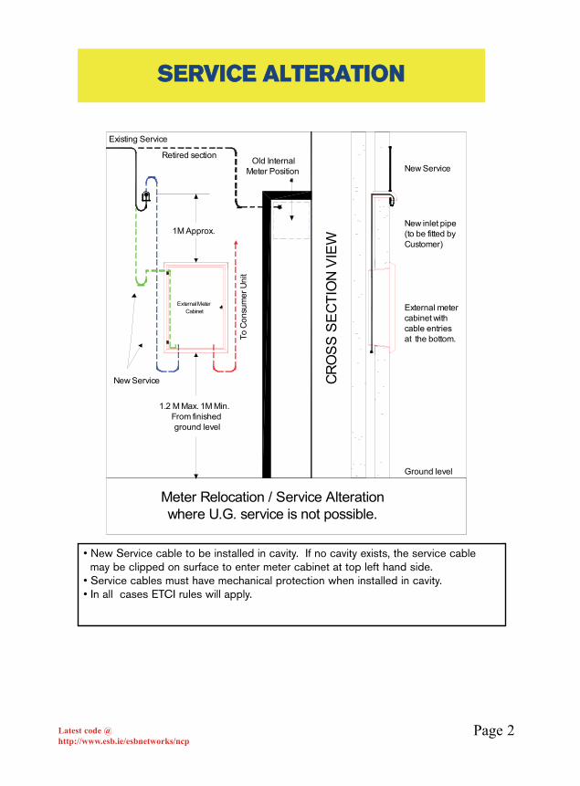
Meter Relocation / Service Alterationwhere U.G. service is not possible.
1.2 M Max. 1M Min. From finished ground level
Old Internal Meter Position
To C
onsu
mer
Uni
t
Existing Service
1M Approx.
New Service
• New Service cable to be installed in cavity. If no cavity exists, the service cable may be clipped on surface to enter meter cabinet at top left hand side.
• Service cables must have mechanical protection when installed in cavity.• In all cases ETCI rules will apply.
SSEERRVVIICCEE AALLTTEERRAATTIIOONN

Page 3Latest code @http://www.esb.ie/esbnetworks/ncp
• Where specified by ESB Networks, a cable run longer than 50m (approx.) mayrequire a larger duct and or an approved service vault or both.• If a 125mm service duct is specified, an ESB Networks approved Service vault will
be required at the interface with the hockey stick• See Current “ESB Networks Specification for underground Service” .• 10mm Draw rope in one continuous length.• In all cases ETCI rules will apply. Circuits shown are for example only.
SSPPEECCIIFFIICCAATTIIOONN FFOORR SSIINNGGLLEE UUNNDDEERR GGRROOUUNNDDSSEERRVVIICCEE CCOONNNNEECCTTEEDD TTOO OOVVEERRHHEEAADD NNEETTWWOORRKK
Flange of cabinet to be water sealed and
polythene damp proof course to be fitted
Tails from customersFuse Board
10 mm draw-in rope to pull in service cables.
All cables to enter the meter box at the bottom.
"Hockey Stick Duct" to project 25 mm into box
ESB Networks approved hockey stick
(diameter 44mm)1.
2 M
Max
1M
Min
.
From
fini
shed
gro
und
leve
l
Drainage slots atlowest level
ESB Networks Pole (Existing)
ESB Networks Approved 50mm Solid Wall MDPE/PVC Red Duct at 600mm Depth
ESB Networks provide cable protection from ground level to Network Connection
ESB Networks approved warning tape at 300mm depthWAR NIN G
E LECTRI CITY SUP PLY CABLE DU CT BE LOW
Page 4Latest code @http://www.esb.ie/esbnetworks/ncp
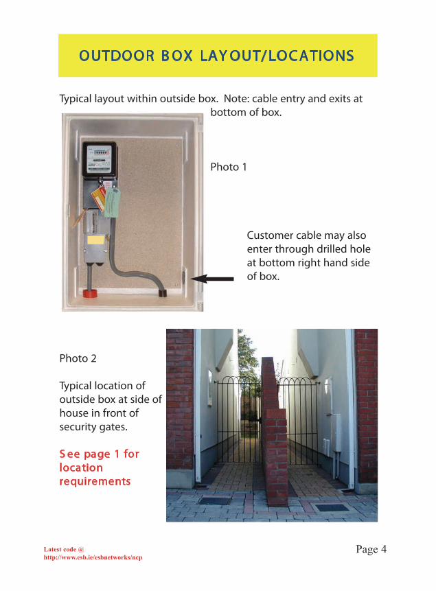
Typical layout within outside box. Note: cable entry and exits atbottom of box.
Photo 1
Customer cable may also enter through drilled hole at bottom right hand side of box.
Photo 2
Typical location of outside box at side of house in front of security gates.
S ee page 1 forlocationrequirements
OUTDOOR B OX LAY OUT/ LOC ATIONS
Page 5Latest code @http://www.esb.ie/esbnetworks/ncp
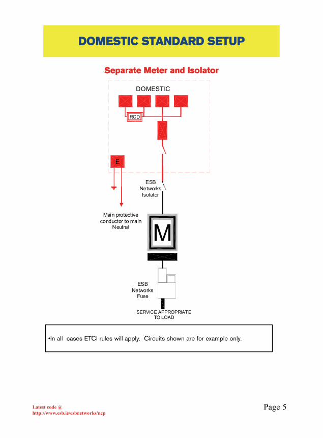
DDOOMMEESSTTIICC SSTTAANNDDAARRDD SSEETTUUPP
M
DOMESTIC
RCD
E
ESB Networks Isolator
Main protective conductor to main
Neutral
ESB Networks
Fuse
SERVICE APPROPRIATE TO LOAD
SSeeppaarraattee MMeetteerr aanndd IIssoollaattoorr
•In all cases ETCI rules will apply. Circuits shown are for example only.
Page 6Latest code @http://www.esb.ie/esbnetworks/ncp
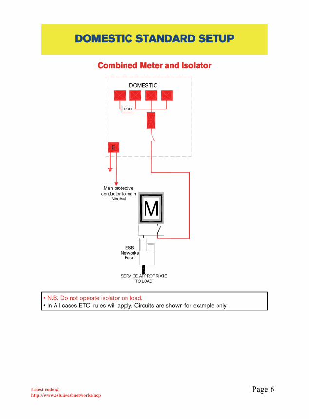
DDOOMMEESSTTIICC SSTTAANNDDAARRDD SSEETTUUPP
M
DOMESTIC
RCD
E
Main protective conductor to main
Neutral
ESB Networks
Fuse
SERVICE APPROPRIATE TO LOAD
CCoommbbiinneedd MMeetteerr aanndd IIssoollaattoorr
• N.B. Do not operate isolator on load.• In All cases ETCI rules will apply. Circuits are shown for example only.

Page 7Latest code @http://www.esb.ie/esbnetworks/ncp
DDOOMMEESSTTIICC PPLLUUSS SSTTOORRAAGGEE HHEEAATTIINNGG
M
NSHDOMESTIC
RCD
NSH
M
E
ESB Networks Isolator
Main protective conductor to main
Neutral
ESB Networks
Fuse
SERVICE APPROPRIATE TO LOAD
ESB Networks Isolator
DDOOMMEESSTTIICC PPLLUUSS SSEEPPAARRAATTEE NNSSHH MMEETTEERRUUPP TTOO 1133kkWW NNSSHH**
*Installations involving more than a total of 3kW of NSH Load require advanceapplication to ESB Networks. A charge may apply.• Combination Meter/isolator may be used• In All cases ETCI rules will apply. Circuits are shown for example only.

Page 8Latest code @http://www.esb.ie/esbnetworks/ncp
DDOOMMEESSTTIICC -- DDAAYY//NNIIGGHHTT
M
NSHDOMESTIC
RCD
CONTACTOR N
ROOM THERMOSTAT
(OPTIONAL)
Con
trol P
air
2 x
1.5s
q (B
RO
WN
)
E
ESB Networks IsolatorMain protective
conductor to main Neutral
ESB Networks Fuse
SERVICE APPROPRIATE TO LOAD
DDOOMMEESSTTIICC PPLLUUSS UUPP TTOO 88kkWW NNSSHH** SSWWIITTCCHHIINNGG TTHHRROOUUGGHH CCOONNTTAACCTTOORR
*Installations involving more than a total of 3kW of NSH Load require advanceapplication to ESB Networks. A charge may apply.
• Double Tariff Meter/Isolator combination also available.• In all cases ETCI rules will apply. Circuits shown are for example only.• Maximum permissable switching current to customer’s contactor shall be ≤80mA.
Page 9Latest code @http://www.esb.ie/esbnetworks/ncp
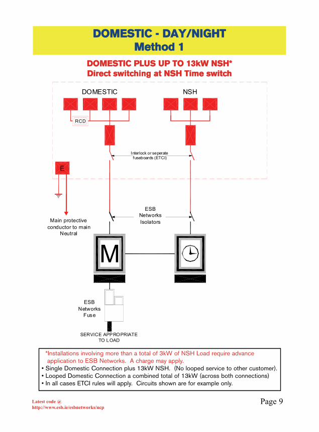
DDOOMMEESSTTIICC -- DDAAYY//NNIIGGHHTT MMeetthhoodd 11
M
DOMESTIC
RCD
NSH
E
Interlock or seperatefuseboards (ETCI)
ESB Networks IsolatorsMain protective
conductor to main Neutral
ESB Networks
Fuse
SERVICE APPROPRIATE TO LOAD
DDOOMMEESSTTIICC PPLLUUSS UUPP TTOO 1133kkWW NNSSHH** DDiirreecctt sswwiittcchhiinngg aatt NNSSHH TTiimmee sswwiittcchh
*Installations involving more than a total of 3kW of NSH Load require advanceapplication to ESB Networks. A charge may apply.
• Single Domestic Connection plus 13kW NSH. (No looped service to other customer). • Looped Domestic Connection a combined total of 13kW (across both connections)• In all cases ETCI rules will apply. Circuits shown are for example only.

Page 10Latest code @http://www.esb.ie/esbnetworks/ncp
DDOOMMEESSTTIICC -- DDAAYY//NNIIGGHHTTMMeetthhoodd 22
M
DOMESTIC
RCD
CONTACTOR N
ROOMTHERMOSTAT(OPTIONAL)
Con
trol P
air 2
x 1
.5sq
(BR
OW
N)
NSH
Tails to comply with ETCI Regulations.
E
ESB Networks IsolatorMain protective
conductor to main Neutral
ESB Networks
Fuse
SERVICE APPROPRIATE TO LOAD
Interlock or seperatefuseboards (ETCI)
DDOOMMEESSTTIICC PPLLUUSS UUPP TTOO 1133kkWW NNSSHH** CCoonnttaaccttoorr sswwiittcchhiinngg NNSSHH
*Installations involving more than a total of 3kW of NSH Load require advanceapplication to ESB Networks. A charge may apply.
• In all cases ETCI rules will apply. Circuits shown are for example only.• Maximum permissable switching current to customer’s contactor shall be ≤80mA.

Page 11Latest code @http://www.esb.ie/esbnetworks/ncp
DDOOMMEESSTTIICC OORR CCOOMMMMEERRCCIIAALLWWIITTHH NNSSHH LLOOAADDSS IINN EEXXCCEESSSS OOFF 1133kkWW
MC
ontr
ol P
air 2
x 1
.5sq
(BR
OW
N)
CONTACTOR N
RCD
DOMESTIC OR GENERAL PURPOSE NIGHT STORAGE HEATING
COIL
Whereappropriate
E
Note: Sealed Dome (provided by
ESB Networks) must be used.
Main protective conductor to main
Neutra l
ESB Networks
Fuse
SERVICE APPROPRIATE TO LOAD
SSIINNGGLLEE PPHHAASSEE CC..TT.. MMEETTEERRIINNGG((33 PPHHAASSEE CCOONNNNEECCTTIIOONN NNOOTT AAVVAAIILLAABBLLEE))
*Installations involving more than a total of 3kW of NSH Load require advanceapplication to ESB Networks. A charge may apply.
• Service appropriate to Load• In outdoor locations standard outdoor cabinet with 150A window type CT in
suitable box 125 x 125mm with sealing bush. No file terminals.• In indoor locations standard CT cabinet with file terminals should be used.• An option of separate night storage heating meter is available.• In all cases ETCI rules will apply. Circuits shown are for example only.• Maximum permissable switching current to customer’s contactor shall be ≤80mA.

Page 12Latest code @http://www.esb.ie/esbnetworks/ncp
DDOOMMEESSTTIICC OORR CCOOMMMMEERRCCIIAALLWWIITTHH NNSSHH LLOOAADDSS IINN EEXXCCEESSSS OOFF 1133kkWW
CONTACTOR N
RCD
DOMESTIC OR GENERAL PURPOSE NIGHT STORAGE HEATING
M
COIL
Whereappropriate
Con
trol P
air
2x1.
5sq
mm
(BR
OW
N)
Ensure that the contactor coil and time switch are fed from the R phase.
E
ESB Networks Isolator
Main protective conductor to main
Neutral
ESB Networks
Fuses
SERVICE APPROPRIATE TO LOAD
33 PPHHAASSEE CCOONNNNEECCTTIIOONN AAVVAAIILLAABBLLEE DDaayy//NNiigghhtt MMeetteerriinngg
*Installations involving more than a total of 3kW of NSH Load require advance application to ESB Networks. A charge may apply.
• ESB Networks isolator will only apply up to 80amp service.• See page 21/22 for space required for ESB Networks main fuse.• In all cases ETCI Rules will apply. Circuits shown are for example only.• An option of separate night storage heating meter is available.• Maximum permissable switching current to customer’s contactor shall be ≤80mA.
Page 13Latest code @http://www.esb.ie/esbnetworks/ncp
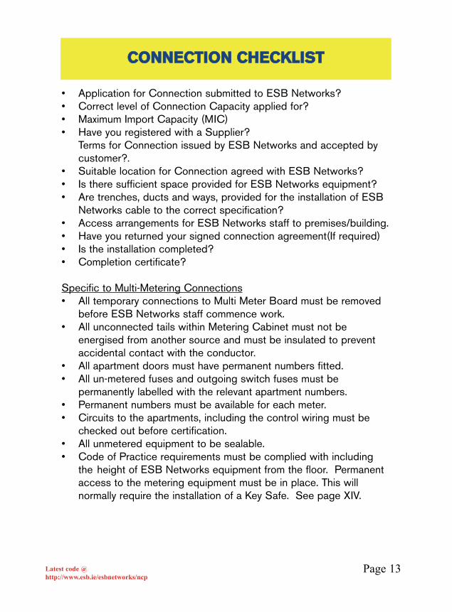
• Application for Connection submitted to ESB Networks?• Correct level of Connection Capacity applied for? • Maximum Import Capacity (MIC)• Have you registered with a Supplier?
Terms for Connection issued by ESB Networks and accepted bycustomer?.
• Suitable location for Connection agreed with ESB Networks?• Is there sufficient space provided for ESB Networks equipment?• Are trenches, ducts and ways, provided for the installation of ESB
Networks cable to the correct specification?• Access arrangements for ESB Networks staff to premises/building.• Have you returned your signed connection agreement(If required)• Is the installation completed?• Completion certificate?
Specific to Multi-Metering Connections• All temporary connections to Multi Meter Board must be removed
before ESB Networks staff commence work.• All unconnected tails within Metering Cabinet must not be
energised from another source and must be insulated to preventaccidental contact with the conductor.
• All apartment doors must have permanent numbers fitted.• All un-metered fuses and outgoing switch fuses must be
permanently labelled with the relevant apartment numbers.• Permanent numbers must be available for each meter.• Circuits to the apartments, including the control wiring must be
checked out before certification.• All unmetered equipment to be sealable.• Code of Practice requirements must be complied with including
the height of ESB Networks equipment from the floor. Permanent access to the metering equipment must be in place. This willnormally require the installation of a Key Safe. See page XIV.
CCOONNNNEECCTTIIOONN CCHHEECCKKLLIISSTT

Page 14Latest code @http://www.esb.ie/esbnetworks/ncp
AAllll ssiinnggllee ccuussttoommeerr,, oouuttssiiddee eenncclloossuurreess ffoorr EESSBB NNeettwwoorrkkss mmeetteerriinnggeeqquuiippmmeenntt sshhaallll ccoommppllyy wwiitthh EETTCCII ““CCooddee ooff PPrraaccttiiccee ffoorr tthhee DDeessiiggnnaanndd EErreeccttiioonn ooff LLooww VVoollttaaggee SSwwiittcchhggeeaarr AAsssseemmbblliieess””..
AAllll oouuttssiiddee eenncclloossuurreess uusseedd ffoorr EESSBB NNeettwwoorrkkss’’ eeqquuiippmmeenntt mmuusstt bbeeIIPP5555 aanndd eeiitthheerr nnoonn--mmeettaalllliicc,, ssttaaiinnlleessss sstteeeell oorr hhoott ddiipp ggaallvvaanniisseedd..WWhheerree mmuullttii--ccuussttoommeerr cceennttrraalliisseedd mmeetteerriinngg iiss ppeerrmmiitttteedd oouuttddoooorrss,,pplleeaassee rreeffeerr ttoo ppaaggee VVllllll ffoorr ssppeecciiaall mmiinniimmuumm rreeqquuiirreemmeennttss..
NN..BB.. CCuussttoommeerr’’ss mmaaiinn eeaarrtthh tteerrmmiinnaall bbaarr mmuusstt nnoott bbee wwiitthhiinn EESSBB NNeettwwoorrkkss’’ sseeaalleedd eenncclloossuurree.
11.. PPrroovviiddee sseeaalliinngg ffaacciilliittiieess aatt ::• Main Isolator.• Un-metered cable/busbar sections.• Un-metered fuses. (individual sealing)• Shrouding around un-metered fuse units.• Meter mounting plate.• All surface mounted trunking used for unmetered wiring.excluding
panel trunking• All unmetered equipment.
22.. SShhrroouuddiinngg ((AAtt UUnnmmeetteerreedd FFuusseess))• 80/125 Amp front loading fuses must have a front loading cover that
has one continuous piece with separate windows cut at 20mm spacing between each fuse
• NH type Fuse units shrouding to minimum IP2X.
33.. DDiivviiddeerrss• Metered and un-metered sections separated.• Un-metered fuse sections separated from other live equipment.
(To allow replacement in safety)
44.. CCuussttoommeerrss OOuuttggooiinngg FFiillee TTeerrmmiinnaallss:: • All terminals shrouded.
55.. LLaabbeelllliinngg ::• On un-metered fuses • On meters• On control wiring • On time-switches• On Customers outgoing switchfuse or MCB
AASSSSEEMMBBLLEERR''SS CCHHEECCKKLLIISSTT
Page 15Latest code @http://www.esb.ie/esbnetworks/ncp
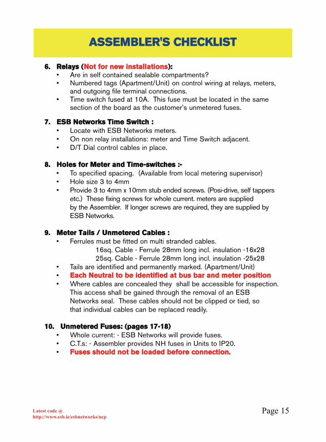
66.. RReellaayyss ((NNoott ffoorr nneeww iinnssttaallllaattiioonnss))::• Are in self contained sealable compartments?• Numbered tags (Apartment/Unit) on control wiring at relays, meters,
and outgoing file terminal connections.• Time switch fused at 10A. This fuse must be located in the same
section of the board as the customer’s unmetered fuses.
77.. EESSBB NNeettwwoorrkkss TTiimmee SSwwiittcchh ::• Locate with ESB Networks meters.• On non relay installations: meter and Time Switch adjacent. • D/T Dial control cables in place.
88.. HHoolleess ffoorr MMeetteerr aanndd TTiimmee--sswwiittcchheess ::--• To specified spacing. (Available from local metering supervisor)• Hole size 3 to 4mm• Provide 3 to 4mm x 10mm stub ended screws. (Posi-drive, self tappers
etc.) These fixing screws for whole current. meters are supplied by the Assembler. If longer screws are required, they are supplied by ESB Networks.
99.. MMeetteerr TTaaiillss // UUnnmmeetteerreedd CCaabblleess ::• Ferrules must be fitted on multi stranded cables.
16sq. Cable - Ferrule 28mm long incl. insulation -16x2825sq. Cable - Ferrule 28mm long incl. insulation -25x28
• Tails are identified and permanently marked. (Apartment/Unit)• EEaacchh NNeeuuttrraall ttoo bbee iiddeennttiiffiieedd aatt bbuuss bbaarr aanndd mmeetteerr ppoossiittiioonn• Where cables are concealed they shall be accessible for inspection.
This access shall be gained through the removal of an ESB Networks seal. These cables should not be clipped or tied, so that individual cables can be replaced readily.
1100.. UUnnmmeetteerreedd FFuusseess:: ((ppaaggeess 1177--1188))• Whole current: - ESB Networks will provide fuses.• C.T.s: - Assembler provides NH fuses in Units to IP20.• FFuusseess sshhoouulldd nnoott bbee llooaaddeedd bbeeffoorree ccoonnnneeccttiioonn..
AASSSSEEMMBBLLEERR''SS CCHHEECCKKLLIISSTT
Page 16Latest code @http://www.esb.ie/esbnetworks/ncp
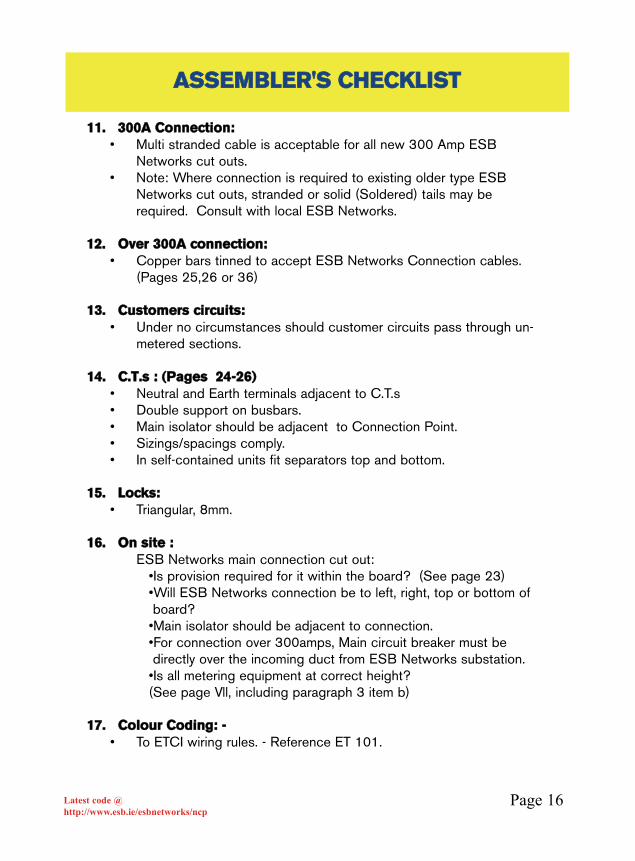
1111.. 330000AA CCoonnnneeccttiioonn::• Multi stranded cable is acceptable for all new 300 Amp ESB
Networks cut outs.• Note: Where connection is required to existing older type ESB
Networks cut outs, stranded or solid (Soldered) tails may be required. Consult with local ESB Networks.
1122.. OOvveerr 330000AA ccoonnnneeccttiioonn::• Copper bars tinned to accept ESB Networks Connection cables.
(Pages 25,26 or 36)
1133.. CCuussttoommeerrss cciirrccuuiittss::• Under no circumstances should customer circuits pass through un-
metered sections.
1144.. CC..TT..ss :: ((PPaaggeess 2244--2266))• Neutral and Earth terminals adjacent to C.T.s• Double support on busbars.• Main isolator should be adjacent to Connection Point.• Sizings/spacings comply.• In self-contained units fit separators top and bottom.
1155.. LLoocckkss:: • Triangular, 8mm.
1166.. OOnn ssiittee ::ESB Networks main connection cut out:
•Is provision required for it within the board? (See page 23)•Will ESB Networks connection be to left, right, top or bottom of board?
•Main isolator should be adjacent to connection.•For connection over 300amps, Main circuit breaker must be directly over the incoming duct from ESB Networks substation.
•Is all metering equipment at correct height?(See page Vll, including paragraph 3 item b)
1177.. CCoolloouurr CCooddiinngg:: --• To ETCI wiring rules. - Reference ET 101.
AASSSSEEMMBBLLEERR''SS CCHHEECCKKLLIISSTT

Page 17Latest code @http://www.esb.ie/esbnetworks/ncp
80 Amp Fuse units conforming toBS7657 which accept RH/RHLcartridge fuses approved to eitherBS 1631 or BS 88 part 3.
All must be individually sealable.
80/125A front loading unit with 22 x 58 fuse link conforming toIEC 408-269.2
All must be individually sealable.
A 20mm (min) space being leftbetween each unit.
For 3 Phase Metering the unitsmay be ganged to accommodateone seal.
FFUUSSEESS BBEEFFOORREE WWHHOOLLEE CCUURRRREENNTTMMEETTEERRSS IINN MMUULLTTII--MMEETTEERRIINNGG
IINNSSTTAALLLLAATTIIOONNSS

Page 18Latest code @http://www.esb.ie/esbnetworks/ncp
NH type units conforming to IEC/EN 60269-2-1 and DIN 43620, with shrouding conforming to IP 2X enclosing allterminals. NH pull down disconnector approved for connections over 80Amp and up to 300AmpAccess cover of enclosure containing NH units must besealable.
FFUUSSEESS BBEEFFOORREE CCTT MMEETTEERRSS IINN MMUULLTTII--MMEETTEERRIINNGG IINNSSTTAALLLLAATTIIOONNSS
UUPP TTOO 220000 kkVVAA
Page 19Latest code @http://www.esb.ie/esbnetworks/ncp
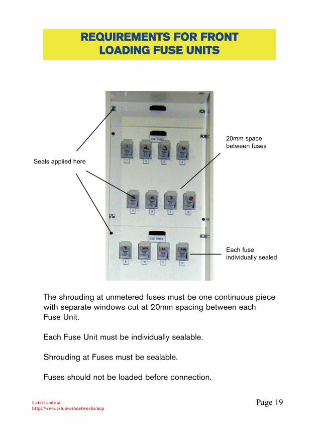
The shrouding at unmetered fuses must be one continuous piecewith separate windows cut at 20mm spacing between eachFuse Unit.
Each Fuse Unit must be individually sealable.
Shrouding at Fuses must be sealable.
Fuses should not be loaded before connection.
RREEQQUUIIRREEMMEENNTTSS FFOORR FFRROONNTTLLOOAADDIINNGG FFUUSSEE UUNNIITTSS
Seals applied here
20mm spacebetween fuses
Each fuseindividually sealed

Page 20Latest code @http://www.esb.ie/esbnetworks/ncp
UUSSEEFFUULL GGEENNEERRAALL DDIIMMEENNSSIIOONNSSCCTT MMeetteerr CCaabbiinneett IInnccoorrppoorraatteedd
iinn MMaaiinn PPaanneell EEnncclloossuurree DDiimmeennssiioonnss
•• EEnncclloossuurree mmuusstt bbee llooccaatteedd ddiirreeccttllyy aaddjjaacceenntt ttoo CCTT eenncclloossuurree oonn lleefftt oorr rriigghhtt hhaanndd ssiiddee oorr aabboovvee..
•• FFoorr tthhee lleefftt oorr rriigghhtt ooppttiioonn,, bboottttoomm ooff mmeetteerr eenncclloossuurree mmuusstt bbee aatt tthhee ssaammee lleevveell aass bboottttoomm ooff CCTT eenncclloossuurree..
• Minimum depth 200mm clearances from back plate to nearest intrusion on insideof door.
• Maximum depth 250mm (back plate to door).• 100mm Trunking installed as shown.• Secondary cables from CT enclosure must enter 100mm trunking.• Enclosure to have hinged door, 8mm triangular lock.• In all cases ETCI rules will apply. Circuits shown are for example only
Minimum 350mm
100mm Trunking
Meter Enclosure
Minimum height to floor level 600mm
Max 2M from floor level Minimum
750mmInternal
Page 21Latest code @http://www.esb.ie/esbnetworks/ncp
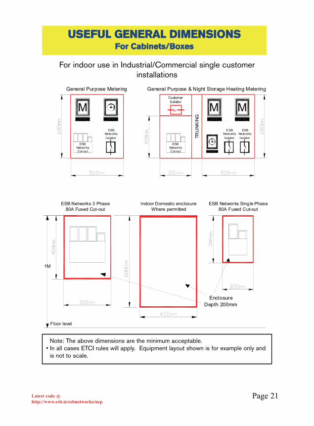
UUSSEEFFUULL GGEENNEERRAALL DDIIMMEENNSSIIOONNSSFFoorr CCaabbiinneettss//BBooxxeess
TRU
NK
ING
General Purpose Metering General Purpose & Night Storage Heating Metering
ESB Networks 3 Phase80A Fused Cut-out
ESB Networks Sing le Phase80A Fused Cut-out
M MM
ESB Networks Cut-out
CustomerIsolator
EnclosureDepth 200mm
1M
Floor level
ESB Networks Iso lator
ESB Networks Cut-out
E SB Networks Isolator
ESB Networks Iso lator
Indoor Domestic enclosureWhere permitted
For indoor use in Industrial/Commercial single customerinstallations
Note: The above dimensions are the minimum acceptable.• In all cases ETCI rules will apply. Equipment layout shown is for example only and
is not to scale.

Page 22Latest code @http://www.esb.ie/esbnetworks/ncp
UUSSEEFFUULL GGEENNEERRAALL DDIIMMEENNSSIIOONNSSFFoorr MMuullttii MMeetteerriinngg PPaanneellss
SinglePhaseMeter
3 PhaseMeter
80 AmpTimeswitch
Trunking 100 mm (Min.) Trunking 100 mm (Min.)
Trunking 100 mm (Min.)
150mm
200mm
160mm
230m
m
355m
m
240m
m
For Multi metering Panels
150mm clear space must be left from meter mounting surface to nearest intrusion inside door.
100mm Trunking (min) to be used as indicated
ESB Networks Isolator dimensions:• 3Ph 120 x 115 x 80mm• 1Ph 120 x 70 x 80mm (type 1)• 1Ph 90 x 90 x 80mm (type 2)
•In all cases ETCI rules will apply.

Page 23Latest code @http://www.esb.ie/esbnetworks/ncp
UUSSEEFFUULL GGEENNEERRAALL DDIIMMEENNSSIIOONNSSSSPPAACCEE RREEQQUUIIRREEDD FFOORR EESSBB NNeettwwoorrkkss
CCAABBLLEE TTEERRMMIINNAATTIIOONNSS << 330000AA
300 A
300mm Deep
Note : Removable base plate required in order to bend cable into position when terminating.
Preferred OptionWall mounted outside switchboard Minimum space required as below
If required to insta ll in an enclosure, Minimum dimensions as below.Please see enclosure base options for cable entry
Option 2Split Base to accomodate cable insta llation.
Option 1Slotted Base to accomodate cable installation.
Floor level
Incl
udes
Hea
der T
runk
ing
of 1
00m
m
(1M
min
imum
)
1.2M
600mm600mm
• Where cut out is wall mounted outside switchboard, adequate mechanical protection must be provided for incoming cable
• The slot for cable entry is required in base plate only.• In all cases ETCI rules will apply.

Page 24Latest code @http://www.esb.ie/esbnetworks/ncp
UUSSEEFFUULL GGEENNEERRAALL DDIIMMEENNSSIIOONNSSFFOORR CCTT EENNCCLLOOSSUURREESS
Min. 500mm
Min.380mm
250/5A C.T. Enclosure
E
• CTs shall be enclosed under a sealable cover.• Where this enclosure is metal it shall be hinged as well as sealable.• Load Neutral and Earth Bar to be provided in enclosure.• Height and width dimensions of CT enclosure may be reversed• Maximum depth of mounting surface 250mm.• Note: in Multi CT meter installations, the MINIMUM height above floor level for
mounting the the CTs is 600mm.• In all cases ETCI rules will apply.

Page 25Latest code @http://www.esb.ie/esbnetworks/ncp
UUSSEEFFUULL GGEENNEERRAALL DDIIMMEENNSSIIOONNSSCCTT CCOONNNNEECCTTIIOONNSS
E
130mm 110mm 100mm
Supports
Dia.8mm
Dia.8mm
SupportsDouble
For 1 or 2 Cables per phase
under 600 Amps.
For 3 Cables per Phase
over 600 Amps
Dia.8mm
40mm x 10 mmTinned Copper
80mm x 10mmTinn ed Copper
800mm from floor
leve l
Detail for back to back cable connection
170mm
70mm70mm
Typica l Main
P rotective Conductor Connection
point
PPRROOVVIISSIIOONN AATT CCUUSSTTOOMMEERRCCIIRRCCUUIITT BBRREEAAKKEERR FFOORR 225500//55 aanndd 660000//55 CCTTss
• For angled drops from CB 100mm spacing must be maintained.• Coppers to be mounted with 60mm clearance from front or back• Copper bars must be tinned because there are aluminium lugs on the
Networks cable.• Neutral bar and Earth Bar can be accommodated at bottom of enclosure• When this enclosure is metal it shall be hinged as well as sealable.• Cable connection bolt hole diameter 16mm• CT bolt hole diameter 12 mm• Note: in Multi CT meter installations, the MINIMUM height above floor level for
mounting the the CTs is 600mm.• Current Transformers rated at 250/5A can safely carry currents of up to 400A• Current Transformers rated at 600/5A can safely carry currents of up to 1000A• In all cases ETCI rules will apply.
Page 26Latest code @http://www.esb.ie/esbnetworks/ncp
UUSSEEFFUULL GGEENNEERRAALL DDIIMMEENNSSIIOONNSSCCTT CCOONNNNEECCTTIIOONNSS
E
Dia.8mm
Typical Main Protective
Conductor Connection
point
800mm from floor
level
40mm
40mm
40mm
130mm 100mm
Double Supports
Double Supports
70mm
150mm
Detail for back to back cable connection
80mm x 10mmTinned Copper
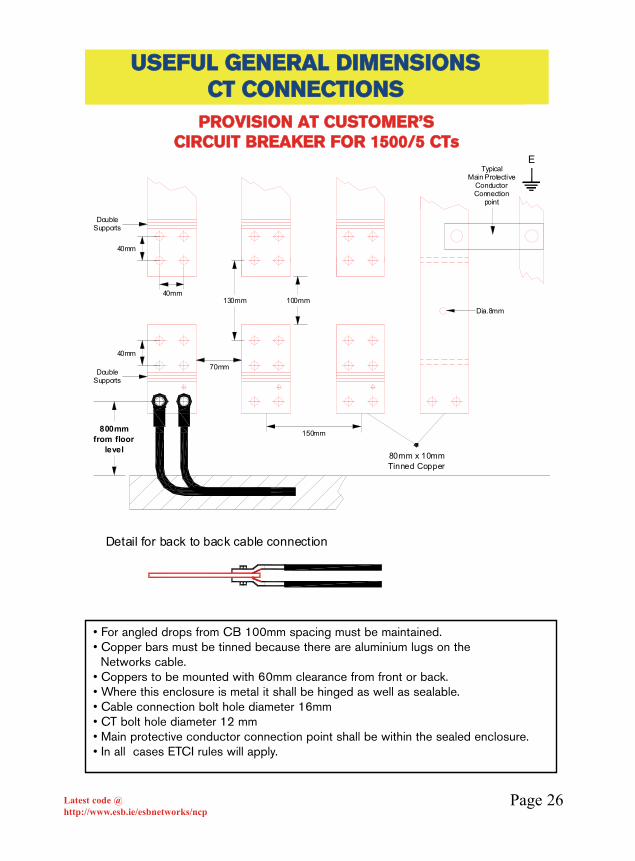
PPRROOVVIISSIIOONN AATT CCUUSSTTOOMMEERR’’SSCCIIRRCCUUIITT BBRREEAAKKEERR FFOORR 11550000//55 CCTTss
• For angled drops from CB 100mm spacing must be maintained.• Copper bars must be tinned because there are aluminium lugs on the
Networks cable.• Coppers to be mounted with 60mm clearance from front or back.• Where this enclosure is metal it shall be hinged as well as sealable.• Cable connection bolt hole diameter 16mm• CT bolt hole diameter 12 mm• Main protective conductor connection point shall be within the sealed enclosure.• In all cases ETCI rules will apply.
Page 27Latest code @http://www.esb.ie/esbnetworks/ncp
DDOOMMEESSTTIICC PPLLUUSS NNSSHH
Refer to page 23 Space required for cable terminations
Sw-Fuse/McbTo comply with ETCI
1m
BUS BARCHAM BER
M
M
NSH
M
NSH
M
M M
0.6
Min
to b
otto
m o
f met
er2M
Max
. to
top
of M
eter
0.2M
Min
to b
otto
m
of fu
ses
For fuse type see page 17
ESB Networks CUT OUT
Control pair from each apartment.
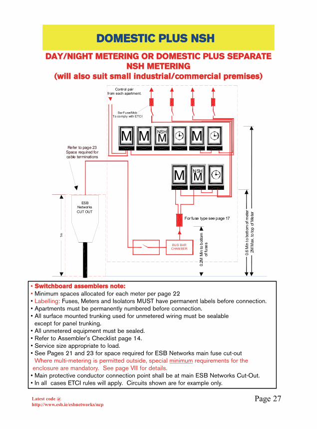
DDAAYY//NNIIGGHHTT MMEETTEERRIINNGG OORR DDOOMMEESSTTIICC PPLLUUSS SSEEPPAARRAATTEENNSSHH MMEETTEERRIINNGG
((wwiillll aallssoo ssuuiitt ssmmaallll iinndduussttrriiaall//ccoommmmeerrcciiaall pprreemmiisseess))
• SSwwiittcchhbbooaarrdd aasssseemmbblleerrss nnoottee::• Minimum spaces allocated for each meter per page 22• Labelling: Fuses, Meters and Isolators MUST have permanent labels before connection.• Apartments must be permanently numbered before connection.• All surface mounted trunking used for unmetered wiring must be sealable
except for panel trunking.• All unmetered equipment must be sealed.• Refer to Assembler's Checklist page 14.• Service size appropriate to load.• See Pages 21 and 23 for space required for ESB Networks main fuse cut-out
Where multi-metering is permitted outside, special minimum requirements for theenclosure are mandatory. See page Vlll for details.
• Main protective conductor connection point shall be at main ESB Networks Cut-Out.• In all cases ETCI rules will apply. Circuits shown are for example only.

Page 28Latest code @http://www.esb.ie/esbnetworks/ncp
• Labelling: Fuses, Meters and Isolators MUST have permanent labels before connection.• Apartments must be permanently numbered before connection.• All surface mounted trunking used for unmetered wiring must be sealable
except panel trunking.• All unmetered equipment must be sealed.• Refer to “Assembler's Checklist” page 14.• Service size appropriate to load.• See Pages 21 and 23 for space required for ESB Networks main fuse Cut-Out.
Where multi-metering is permitted outside, special minimum requirements for theenclosure are mandatory. See page Vlll for details.
• Main protective conductor connection point shall be at main ESB networks Cut-Out.• In all cases ETCI rules will apply. Circuits shown are for example only
AAPPAARRTTMMEENNTTSS DDAAYY//NNIIGGHHTT EELLEECCTTRROONNIICC MMEETTEERRIINNGG FFRROOMM 22000088
BUS BARCHAMBER
ESB NetworksCut-Out
Refe r to page 23 for Sp ace required for cable terminations
Sw-Fuse/McbTo comply w ith ETCI
1m
M MM M M M
M M M M M
0.6
Min
to b
otto
m o
f met
er2M
Max
. to
top
of M
eter
0.2M
Min
to b
otto
m
of fu
ses
For fuse type see page 17
Co ntrol pair from each apartment.
DDAAYY//NNIIGGHHTT MMEETTEERRIINNGG TTOO SSWWIITTCCHH NNSSHH CCOONNTTAACCTTOORRSS..((WWiillll aallssoo ssuuiitt ssmmaallll iinndduussttrriiaall//ccoommmmeerrcciiaall pprreemmiisseess))

Page 29Latest code @http://www.esb.ie/esbnetworks/ncp
• 10 Amp fused feed to each time switch from unmetered connection (fuse supplied bycustomer) Labelled Time switch feed fuse mmuusstt bbee llooccaatteedd with all other unmeteredfuses. Time Switch to be surface mounted at eye level.
• Relay wiring - 1.5sq.mm flexible or stranded single P.V.C. cable. d1 red/blue d2 brown/white. NOTE: all cable connections must be fitted with ferrules of the correct length.
• Control cable to be labelled with flat/unit identifiers at outgoing file terminals, at both sides of the relay and at the meter.
• Relays to be in a sealed, sseellff ccoonnttaaiinneedd enclosure.• Relays to be of an approved type with CE mark and must comply with IEC 60947, or
equivalent EU National Standard e.g. BS, VDE.• Relays to be interchangeable and mounted on Din Rail.• Relay coils to be rated at 230V, with 8 normally open contacts rated at 400V.• In all cases ETCI rules will apply. Circuits shown are for example only.
d1 d1
13 14
23 24
33 34
43 44
53 54
63 64
73 74
83 8483 84
73
63
53
43
74
64
44
54
13
23
33
14
34
24
A1 A2 A1 A2
N
L
POSITIONIN NIGHTSWITCH SHOWN
CONTAC T STATESWITCHING TIME
DT (d1)
ON 0800OFF 2300
N.S.H. (d2)
ON 2300OFF 0800
73 74
A2A1
d2
83 84
53
63
33
43
23
13
54
64
44
34
14
24
7473
A1
d2
83
A2
84
53
63
43
33
54
64
44
34
13
23
14
24
To N.S.H. contac tor coil circuits.
Bro
wn
Whi
te
Example of 1 installationCan be repeated by up to 16 per time c lock
Red
Blue
M
TIME SWITCH(Minimum space reqd. for T/S: 230mm high X 150mm wide)
RREELLAAYY CCOONNTTRROOLL DDIIAAGGRRAAMMNNOOTT FFOORR NNEEWW IINNSSTTAALLLLAATTIIOONNSSSSUUIITTAABBLLEE FFOORR DDAAYY//NNIIGGHHTT MMUULLTTIIMMEETTEERRIINNGG
NNoottee:: AAllll ccoonnttrrooll wwiirriinngg iinncclluuddiinngg ccoonnnneeccttiioonnss ttoo ttiimmee sswwiittcchh aanndd rreellaayy ccooiillss pprroovviiddeedd bbyy ccuussttoommeerr..
Not for new installations

Page 30Latest code @http://www.esb.ie/esbnetworks/ncp
CCOOMMMMEERRCCIIAALL//IINNDDUUSSTTRRIIAALL PPLLUUSSSSEEPPAARRAATTEE NNSSHH uupp ttoo 330000AA ((220000kkVVAA))
For f use type se e page 17
Refer to page 2 3 for Space required for cable terminations
Sw-Fuse/McbTo comply with ETCI
BUS BARCHAMBER
Incl
udes
Hea
der T
runk
ing
of 1
00m
m (m
in)
M
M M
0.6
Min
to b
otto
m o
f met
er2M
Max
. to
top
of M
eter
0.2M
Min
to b
otto
m
of fu
ses
ESB Ne tworks CUT OUT
1m
MMUULLTTII -- CCUUSSTTOOMMEERRSS -- WWHHOOLLEE CCUURRRREENNTTPPHHYYSSIICCAALL LLAAYYOOUUTT ((WWiillll aallssoo ssuuiitt iinndduussttrriiaall pprreemmiisseess))
• Labelling: Fuses, Meters and Isolators MUST have permanent labels beforeconnection.
• Units must be permanently identified before connection.• All surface mounted trunking used for unmetered wiring must be sealable
except panel trunking.• All unmetered equipment must be sealed.• Refer to Assembler's Checklist page 14.
Where multi-metering is permitted outside, special minimum requirements forthe enclosure are mandatory. See page Vlll for details.
• Main protective conductor connection point shall be at main ESB Networks Cut-Out.• In all cases ETCI rules will apply. Circuits shown are for example only.
Page 31Latest code @http://www.esb.ie/esbnetworks/ncp
11.. The final connection arrangements in Commercial Units seldombecome apparent until a very late stage. Therefore, various meteringpermutations should be considered in the main switchboard at thedesign stage. This may avoid subsequent costly alterations.
22.. Page 37 will cater for Multi-Customers.
Pages 32, 33 or 35 will cater for One Customer occupying the entirebuilding with Metering before the customer’s main circuit breaker.
33.. CCeennttrraalliisseedd mmeetteerriinngg iiss tthhee pprreeffeerrrreedd ooppttiioonn..
DDee--cceennttrraalliisseedd MMeetteerriinngg uussiinngg uunnmmeetteerreedd mmaaiinnss iiss aacccceeppttaabblleeiinn ssoommee ””LLiimmiitteedd”” ssiittuuaattiioonnss..
IIff iitt iiss aaggrreeeedd wwiitthh EESSBBNN ttoo hhaavvee ddee--cceennttrraalliisseedd mmeetteerriinnggtthhrroouugghh tthhee uussee ooff uunnmmeetteerreedd mmaaiinnss,, yyoouu mmuusstt ccoonnttaacctt tthheellooccaall EESSBB NNeettwwoorrkkss DDeessiiggnn MMaannaaggeerr aanndd ggeett aaggrreeeemmeennttbbeeffoorree ffiinnaalliissiinngg yyoouurr eelleeccttrriiccaall ddeessiiggnn..
NNOOTTEE:: TThhee iinnssttaallllaattiioonn//ddeessiiggnn ooff uunnmmeetteerreedd mmaaiinnss iissssppeecciiffiieedd bbyy EESSBBNN
NNOOTTEE:: TThhee ccuussttoommeerr oorr aaggeenntt aaccttiinngg oonn ccuussttoommeerr’’ss bbeehhaallffsshhoouulldd ccoonnssuulltt wwiitthh tthhee ssuupppplliieerr ttoo eennssuurree tthhee ccoorrrreecctt ttaarriiffffaapppplliieess ttoo tthhee iinnssttaallllaattiioonn..
PPAARRTTIICCUULLAARR TTOO AAPPAARRTTMMEENNTT//OOFFFFIICCEE BBLLOOCCKKSS

Page 32Latest code @http://www.esb.ie/esbnetworks/ncp
EESSBB NNEETTWWOORRKKSS MMAAIINN CCOONNNNEECCTTIIOONNFFUUSSEEDD UUPP TTOO 330000AA ((220000KKVVAA))
M
Sw-Fuse/MCBTo comply with
ETCI
MC.T. Meter
Option 1Whole Current
Option 2Current Transformer
ESB Networks CUT OUT
ESB Networks CUT OUT
ESB Networks Isolator
Incl
udes
Hea
der T
runk
ing
of 1
00m
m (m
in)
1m
Min
. 1m
Max
1.2
m
Refer to page 23 Space required for cable terminations
AARRRRAANNGGEEMMEENNTT FFOORR OONNEE CCUUSSTTOOMMEERR BBUULLKK TTAARRIIFFFF
• In indoor locations ESB Networks Main Fuse Unit shall be located close to an external door (i.e. within •2m).
• ESB Networks supply and fit Time switches to control meter dials and off peakload.
• For Whole Current Metering up to 100A. ESB Networks Isolator to be used• If Fire Fighting equipment is installed, please refer to page 38.• For meter cabinet sizes please see pages 20, 22 and 40.• In all cases ETCI rules will apply. Circuits shown are for example only.

Page 33Latest code @http://www.esb.ie/esbnetworks/ncp
EESSBB NNEETTWWOORRKKSS MMAAIINN CCOONNNNEECCTTIIOONNFFUUSSEEDD UUPP TTOO 330000AA ((220000KKVVAA))
TO CUSTO MERS EQUIP MENT
M
200Amp / 300AmpE SB Networks Cut
Out
Refer to page 23Space required forca ble terminations
Incl
ude
s H
eade
r Tru
nkin
g of
100
mm
(m
in)
1m
ESB Networks CUT OUT
M
Sw -Fuse/MCBTo comply with ETCI
AARRRRAANNGGEEMMEENNTT FFOORR OONNEE CCUUSSTTOOMMEERR MMUULLTTII--TTAARRIIFFFF
• In indoor locations, ESB Networks Main Fuse Unit shall be located close to an external door (i.e. within •2m).
• The ESB Networks service cable should penetrate no more than 2m on the horizontal from the inside of the main external wall.
• If Fire Fighting equipment is installed, please refer to page 38.• For Cabinet sizes please see page 20, 22 and 40.
Where multi-metering is permitted outside, special minimum requirements are mandatory. See page Vlll for details.
• In all cases ETCI rules will apply. Circuits shown are for example only.

Page 34Latest code @http://www.esb.ie/esbnetworks/ncp
CCOONNNNEECCTTIIOONN OOVVEERR 330000 AAMMPPSS ((220000kkVVAA))
ESB Networks SubElevation View
Customer Switch Room
ESB Networks LT Panel
Customer Main Circuit Breaker
Cable Duct
Customer Main Circuit Breaker
ESB NetworksLT Panel
ESB Networks SubPlan View
Customer Switch Room
Total Cable length notto exceed 10 Metres
NN..BB.. SSoommee llooaaddss ooff lleessss tthhaann 220000kkVVAA mmaayy rreeqquuiirreeaa ssuubbssttaattiioonn iinn uurrbbaann llooccaattiioonnss..DDiirreecctt ccoonnnneeccttiioonn ffrroomm SSuubb SSttaattiioonn
• Customer switch room must be adjoining ESB Networks substation.• Customer’s Main circuit breaker must be located directly over the incoming service
duct from ESBN substation at the point where it enters the customer’s main switch room.
• ESB Networks cable run to Customer Main Circuit Breaker must not be more than10 metres in total•length and no more than 3 metres within the customer’s Switch Room. (ETCI requirement)
• See current general specification for MV substation buildings.• In all cases ETCI rules will apply. Circuits shown are for example only.
Page 35Latest code @http://www.esb.ie/esbnetworks/ncp
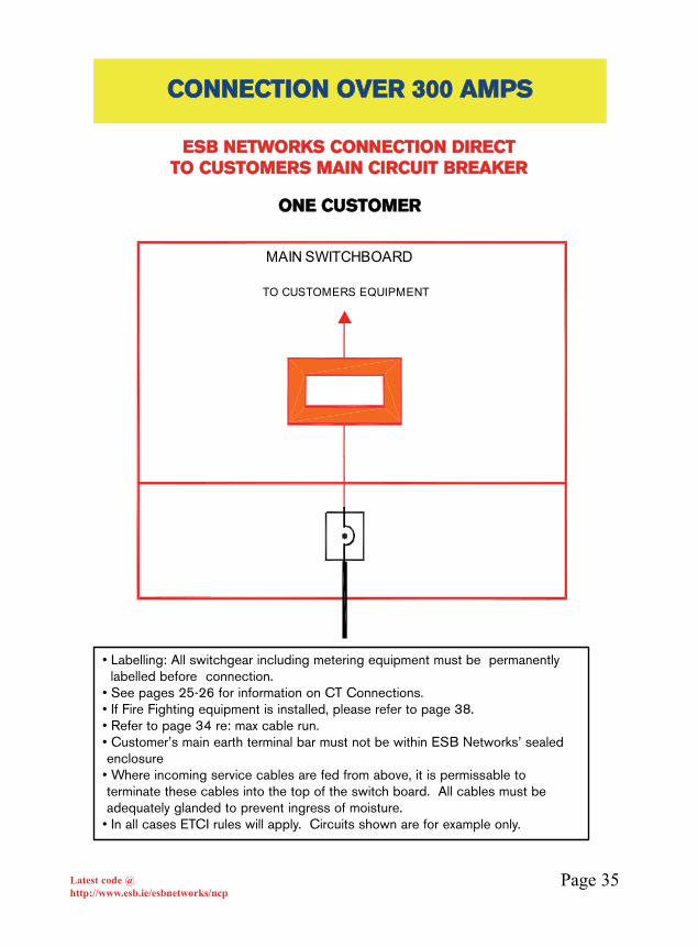
CCOONNNNEECCTTIIOONN OOVVEERR 330000 AAMMPPSS
MAIN SWITCHBOARD
TO CUSTOMERS EQUIPMENT
EESSBB NNEETTWWOORRKKSS CCOONNNNEECCTTIIOONN DDIIRREECCTT TTOO CCUUSSTTOOMMEERRSS MMAAIINN CCIIRRCCUUIITT BBRREEAAKKEERR
OONNEE CCUUSSTTOOMMEERR
• Labelling: All switchgear including metering equipment must be permanently labelled before •connection.
• See pages 25-26 for information on CT Connections.• If Fire Fighting equipment is installed, please refer to page 38.• Refer to page 34 re: max cable run.• Customer’s main earth terminal bar must not be within ESB Networks’ sealedenclosure
• Where incoming service cables are fed from above, it is permissable toterminate these cables into the top of the switch board. All cables must beadequately glanded to prevent ingress of moisture.
• In all cases ETCI rules will apply. Circuits shown are for example only.

Page 36Latest code @http://www.esb.ie/esbnetworks/ncp
CCOONNNNEECCTTIIOONN OOVVEERR 330000 AAMMPPSS
WWhheerree EESSBB NNeettwwoorrkkss ccaabblleess tteerrmmiinnaattee ddiirreeccttllyy oonnttooiinnccoommiinngg mmaaiinn CCiirrccuuiitt BBrreeaakkeerr
• Approved Sealant required at cable entry• Copper bars must be tinned because there are aluminium lugs on the
Networks cable.• Above photograph shows connection to multi-customer installation. Multi-
metering •arrangement as per page 37• In single customer installation CTs are fitted before main CB. The door on
this •enclosure mmuusstt nnoott be interlocked with main CB i.e. separate doors.• Customer’s main earth terminal bar must not be within ESB Networks’ sealed • In all cases ETCI rules will apply.• For ESBN main incoming cable detail, please refer to pages 25 and 26 for busbardrilling details.
Separate Doors

Page 37Latest code @http://www.esb.ie/esbnetworks/ncp
CCOONNNNEECCTTIIOONN OOVVEERR 330000 AAMMPPSS
M M
Switch Fuseor MCCB If required.
For short circuit protection within the
board
Customerover
200 KVA
Switch Fuse/MCBTo comply with ETCI
Lock Off Facility
required
Customerover
200 KVA
Lock Off Facility
required
CCOONNNNEECCTTIIOONN DDIIRREECCTT TTOO CCUUSSTTOOMMEERRSS MMAAIINN CCIIRRCCUUIITTBBRREEAAKKEERR
MMUULLTTII CCUUSSTTOOMMEERRSS -- CCEENNTTRRAALLIISSEEDD MMEETTEERRIINNGG
• Labelling: All switch gear including metering equipment must be permanently labelled before connection.
• Circuit mains connecting each customer must be numbered/labelled at both ends and correspond with unit/door numbers/labels.
• Protection / Short Circuit device controlling unmetered rising main shall be lockable in the OFF position.
• If Fire Fighting equipment is installed, please refer to page 38.• Leave space for CT meter Cabinet.• Refer to page 34 re. max. cable run.• Customer’s main earth terminal bar must not be within ESB Networks’ sealed
enclosure • For connection greater than 200kVA (300A), the Circuit Breaker must have
a lock off facility.• In all cases ETCI rules will apply. Circuits shown are for example only.
Page 38Latest code @http://www.esb.ie/esbnetworks/ncp
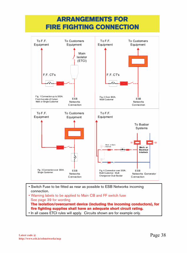
AARRRRAANNGGEEMMEENNTTSS FFOORRFFIIRREE FFIIGGHHTTIINNGG CCOONNNNEECCTTIIOONN
F.F. CT's
Main Isolator(ETCI)
F.F. CT's
To CustomersEquipment
To F.F.Equipment
To F.F.Equipment
To F.F.Equipment
To CustomersEquipment
To CustomersEquipment
To Busbar Systems
C
C
M
Mech. or Electrical Interlock
Mech. or Elect. Interlock
Fig. 1 Connection up to 300A. From live side of Cutout.Multi or Single Customer
Fig. 2 Over 300A. Multi Customer
Fig. 3 Connection over 300A. Single Customer
Fig. 4 Connection over 300A. Multi Customer. Multi Changeover Dual Busbar
To F.F.Equipment
ESB Networks
C onnec tion
ESB Networks
Connect ion
ESB Networks
C onnec tion
ESB Networks
C onnec tionGenerator
• Switch Fuse to be fitted as near as possible to ESB Networks•incoming connection.
• Warning labels to be applied to Main CB and FF switch fuse See page 39 for wordingTThhee iissoollaattiioonn//oovveerrccuurrrreenntt ddeevviiccee ((iinncclluuddiinngg tthhee iinnccoommiinngg ccoonndduuccttoorrss)),, ffoorr ffiirree ffiigghhttiinngg ssuupppplliieess sshhaallll hhaavvee aann aaddeeqquuaattee sshhoorrtt cciirrccuuiitt rraattiinngg..
• In all cases ETCI rules will apply. Circuits shown are for example only.

Page 39Latest code @http://www.esb.ie/esbnetworks/ncp
FFIIRREE FFIIGGHHTTIINNGG SSAAFFEETTYY LLAABBEELLSS
WWoorrddiinngg rreeqquuiirreedd oonn FFiirree FFiigghhttiinngg ((FF//FF)) LLaabbeellss..LLaabbeellss ttoo bbee sseeccuurreellyy ffiitttteedd aatt aapppprroopprriiaattee ppooiinnttss..
LLaabbeellss ffoorr ffiigg.. 11 ppaaggee 3388(a) Label for E.S.B Networks Cut Out
DANGERConnection to F/F
fed from live side ofE.S.B Networks Cut out Fuses
DANGERFed from
live side of E.S.BNetworks
Cut out Fuses
(b) Label for F/F Switch Fuse
LLaabbeellss ffoorr ffiigg.. 22 aanndd ffiigg.. 33 ppaaggee 3388(a) Label for Main Circuit Breaker
DANGERConnection to F/F
fed from live side ofMain CB
DANGERFed from
live side of Main CB
(b) Label for F/F Switch Fuse
LLaabbeellss ffoorr ffiigg.. 44 ppaaggee 3388(a) Label for Main Circuit Breaker, Fire fighting Fuse and Switch Fuse
DANGERConnection to F/F
fed from live side ofMain CB
DANGERConnection to F/F
fed from live side ofGenerator CB
(b) Label for Generator Main Circuit Breakerand Stand-by F/F Switch Fuse

Page 40Latest code @http://www.esb.ie/esbnetworks/ncp
EESSBB NNeettwwoorrkkss MMAAIINN CCOONNNNEECCTTIIOONN OOVVEERR 330000AA ((220000kkVVAA))
PPHHYYSSIICCAALL LLAAYYOOUUTT FFOORR SSIINNGGLLEE CCUUSSTTOOMMEERR
Space for meter cabinet 600 x 600
100mm x 100mm Trunking
Circuit Breaker
ESB Networks C.T.sC.T. Provision as on
pages 25/26
1.0M
To
1.2M
Wall Mounted Switchboard
Floor level
ESB Networks TerminationSpace required for
cable make-off as on pages 25/26
• Separate doors for CTs and CBs.• A clear working space of 1.2m in front of ESB Networks equipment.• In all cases ETCI rules will apply.
Page 41Latest code @http://www.esb.ie/esbnetworks/ncp
SShhooppppiinngg CCeennttrreess::Experience has shown that Meters fitted inside each unit will inevitablybe covered up by permanent shelving and / or display units.Therefore the only suitable and safe location is a centralised switchroom.
Centralised Metering is the preferred method See Page 42.
If Centralised metering cannot be achieved, agreement must besought from the ESB Networks Design Manager regarding meteringlocation.
CCoommmmeerrcciiaall//IInndduussttrriiaall UUnniittss::Centralised metering. See Page 42.
Alternative method: individual connections from ESB Networks.Page 43 shows mini-pillar application
GGeenneerraall
A clear space of 1.2m must always be left in front of ESB Networksequipment.
Standard locking device (8mm Triangular Key outdoor cabinet type)shall be fitted by Customer to provide access to all enclosurescontaining ESB Networks meters/main fuse units.
SSHHOOPPPPIINNGG CCEENNTTRREESS AANNDDCCOOMMMMEERRCCIIAALL//IINNDDUUSSTTRRIIAALL UUNNIITTSS
DDiissccuussssiioonn wwiitthh llooccaall EESSBB NNeettwwoorrkkss ooffffiiccee iiss eesssseennttiiaall dduurriinngg tthhee ppllaannnniinngg ssttaaggee,, aatt wwhhiicchh ttiimmee tthhee aapppprroopprriiaattee
mmeetthhoodd ooff ccoonnnneeccttiioonn//mmeetteerriinngg wwiillll bbee aaggrreeeedd..

Page 42Latest code @http://www.esb.ie/esbnetworks/ncp
SSHHOOPPPPIINNGG CCEENNTTRREESS oorrCCOOMMMMEERRCCIIAALL//IINNDDUUSSTTRRIIAALL UUNNIITTSS
SUPERMARKET
10 11
9
8 7 6 5 4 3 2 1
12 13 14 15 16
Customers Switchgear
Meters here Switchboard
arrangementsPage 37
CCEENNTTRRAALLIISSEEDD MMEETTEERRIINNGG
• Centralised Metering is the preferred option.• In exceptional circumstances de-centralised metering will be considered.• Units requiring connection, must be permanently numbered.• Sufficient space shall be provided for ESB Networks equipment.• Refer to page 21 and 23 for space required for ESB Networks main fuse units.• Refer to page 30 for min/max height of meters.• A clear space of 1.2m shall be left in front of ESB Networks equipment.• Completion Certificates submitted for connection to an individual unit must be for
the completed wiring of the unit and all associated cables from the meter position.• In all cases ETCI rules will apply.

Page 43Latest code @http://www.esb.ie/esbnetworks/ncp
CCOOMMMMEERRCCIIAALL//IINNDDUUSSTTRRIIAALL UUNNIITTSSM
ini P
illar
Min
i Pill
ar
Mini Pillar
ESB NetworksSUB
AALLTTEERRNNAATTIIVVEE MMEETTHHOODD SSHHOOWWIINNGGIINNDDIIVVIIDDUUAALL CCOONNNNEECCTTIIOONNSS FFRROOMM EESSBB NNeettwwoorrkkss
•• EESSBB nneettwwoorrkkss eeqquuiippmmeenntt sshhaallll bbee ffiitttteedd wwiitthhiinn 22 mmeettrreess ooff sshhoopp//uunniitt ddoooorr..• Units requiring connection, must be permanently identified.• Circuit mains connecting each unit must be identified/labelled at both ends and
correspond with unit/identification.• Sufficient space shall be provided for ESB Networks equipment.• Refer to page 21 and 23 for space required for ESB Networks main Fuse Units.• Refer to page 30 for min/max height of meters.• In all cases ETCI rules will apply.

Page 44Latest code @http://www.esb.ie/esbnetworks/ncp
GGRROOUUPPSS OOFF SSHHOOPPSS//OOFFFFIICCEESS
Commercial Unit Commercial Unit
Cutout and
Meters
Office Units Office Units
ES
B N
etw
orks
Min
i Pill
ar
Cutout and
Meters
Heavy duty
cut-out
FFAACCIINNGG OONNTTOO PPUUBBLLIICC RROOAADDWWAAYY
• The appropriate method of connection and metering will be confirmed by the local ESB Networks design office at the planning stage.
•• EESSBB NNeettwwoorrkkss eeqquuiippmmeenntt mmuusstt bbee ffiitttteedd wwiitthhiinn 22mm ooff ccoommmmeerrcciiaall uunniitt ddoooorr.. • Units must be permanently identified.• Circuit mains connecting each unit must be identified/labelled at both ends and
correspond with unit/door identification.• Sufficient space shall be provided for ESB Networks equipment. • Refer to page 21 and 23 for space required for Cut Outs.• Refer to pages Vll and Vlll paragraph 3B for min/max height of metering equipment.• A clear space of 1.2m must be left in front of ESB Networks equipment.• In all cases ETCI rules will apply.

Page 45Latest code @http://www.esb.ie/esbnetworks/ncp
CCOONNNNEECCTTIIOONN FFOORR CCOOMMMMEERRCCIIAALLTTEEMMPPOORRAARRYY IINNSSTTAALLLLAATTIIOONN
M RCD
E
Socket to EN60309/2 standard located outside cabinet.
IP55 Gland where surface
box is used
Main protective conductor to main
Neutral
ESB Networks
FUSE
ESB Networks Isolator
This is the only situation where customer’s equipmentwill be mounted in the same enclosure as ESB Networks equipment.
Note: Customer’s equipment to be mounted on Right Hand Side
•• NN..BB..TThhiiss llaayyoouutt ccaann oonnllyy bbee uusseedd ffoorr CCoommmmeerrcciiaall TTeemmppoorraarryy ssuupppplliieess• This interface sshhaallll nnoott be located at the permanent metering location• Connections for temporary installations should not be installed either within or onthe exterior of any temporary building or structure e.g. portacabins, containers etc.They should only be installed within or on a robust permanent structure that will notbe moved as part of any site works e.g. boundary wall, existing building or speciallyconstructed concrete housing. See Appendix E at back of this publication.
• Enclosures used to house such connections must be made from non-conducting material.
•• SSttaannddaarrdd oouuttddoooorr mmeetteerr ccaabbiinneettss -- ssuurrffaaccee mmoouunntteedd -- aarree nnoott ssuuiittaabbllee ffoorruussee iinn aannyy ssiittuuaattiioonn..
• All installations must comply with ETCI rules. Circuits shown are for example only.

Page 46Latest code @http://www.esb.ie/esbnetworks/ncp
PPEETTRROOLL SSTTAATTIIOONNSS
Steel Wire Armoured Cable
ESB Networks connection
To ESB Networks Metering Equipment
Incl
udes
Hea
der
Trun
king
of
100
mm
(min
)1m
Pil lar supplied bycontractor usuallylocated away frompumps at nearestpoint to roadway.Min. IP44 suppliedby contractor.
• See pages 21 or 23 for space required for ESB Networks Main Fuse Unit.• Control of standby generator shall be arranged to prevent generator start-up if main
isolator is switched off for emergency/maintenance.• Note: enclosure should be sized to allow adequate space for the customer’s
equipment and the ESB Cut out.• N.B. Outside enclosures used for housing ESB Networks’ equipment must
be either non-metallic, stainless steel or hot dip galvanised and have a Minimum IP44 rating. See specific requirements 4 (b) page lX
• In all cases ETCI rules will apply.
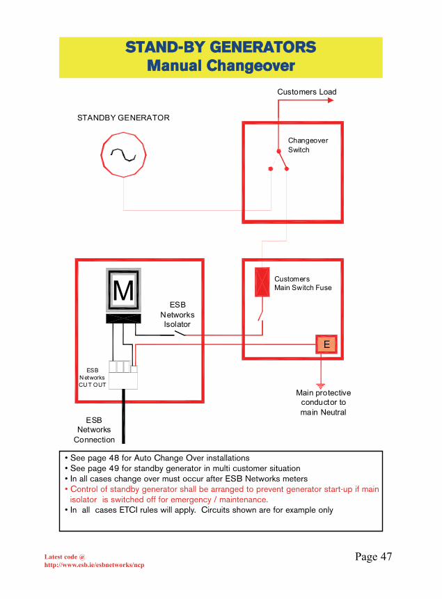
Page 47Latest code @http://www.esb.ie/esbnetworks/ncp
SSTTAANNDD--BBYY GGEENNEERRAATTOORRSSMMaannuuaall CChhaannggeeoovveerr
M
E
CustomersMain Switch Fuse
STANDBY GENERATOR
Changeover Switch
Customers Load
ESB Networks
Connection
ESB N etworks CU T OUT
Main protective conductor to main Neutral
ESB Networks Isolator
• See page 48 for Auto Change Over installations• See page 49 for standby generator in multi customer situation• In all cases change over must occur after ESB Networks meters• Control of standby generator shall be arranged to prevent generator start-up if main
isolator •is switched off for emergency / maintenance.• In all cases ETCI rules will apply. Circuits shown are for example only

Page 48Latest code @http://www.esb.ie/esbnetworks/ncp
SSTTAANNDD--BBYY GGEENNEERRAATTOORRSSAAuuttoo CChhaannggeeoovveerr
ControlRelay
Mechanical or Electrical Interlock
Main C/B Generator C/B
Generator
To Customer's Load
ESB NetworksMeter ing CT's
ESB NetworksConnection
For Auto Change Over Generator installationsplease see the current ETCI Rules
• See page 49 for standby generator in multi customer situation• In all cases change over must occur after ESB Networks meters• Control of standby generator shall be arranged to prevent generator start-up if
main isolator is switched off for emergency /maintenance.• In all cases ETCI rules will apply. Circuits shown are for example only

Page 49Latest code @http://www.esb.ie/esbnetworks/ncp
SSTTAANNDD--BBYY GGEENNEERRAATTOORRSSMMuullttii CCuussttoommeerr
C CM
C C
M
M
Mech. or ElectricalInterlock
Generator
Typical for Whole CurrentMetering
Typical for CT Meteringwith contactors
Typical for CT Meteringwith circuit breakers
Mech. or Electrical Interlock
Mech. or Electrical Interlock
Mechanical or Electr ical Interlock
ESB Networks
Connection
For Auto Change Over Generator installationsplease see the current ETCI Rules
• In all cases change over must occur after ESB Networks meters.• If Fire Fighting (F/F) equipment is installed, see page 38.• Control of standby generator shall be arranged to prevent generator start-up if main
isolator •is switched off for emergency /maintenance.• In all cases ETCI rules will apply. Circuits shown are for example only.
Page 50Latest code @http://www.esb.ie/esbnetworks/ncp
NOTE: It is essential that these requirements are complied with byCustomer/Contractor to ensure prompt installation of ESB Networksconnection cables.
All s ervice terminations s hall be enclos ed within an IP 55 ratedenclos ure. E ntries into s uch enclos ures mus t be glanded to maintainIP 55 s tandards .
An (IP 55) M E TE R E NC LOS UR E (66000 x 4000 xx 220000 minimum) e.g.P olyes ter/ S ta inles s , s teel is required for one s ingle phas e meter(and time s witch if required.). This is provided and ins ta lled bycus tomer to hous e E S B Network s equipment. F or other meteringarrangement a larger enclos ure will be required. The location of theC abinet s hould be agreed with the local E S B Network s officebeforehand, whether indoor OR outdoor.
SPECIFICATION FOR STANDARD UNDERGROUND SERVICESUPPLIED FROM OVERHEAD NETWORK A suitable size red electric cable duct to be provided by Customer in a600mm deep (minimum conditions*) trench from the meter cabinet to ESBNetworks pole. The duct should have a minimum radius bend of 450mm. Theduct should contain a 10mm, strong draw rope to facilitate the pulling in ofESB Networks service cable.
ESB Networks approved warning tape “Electric cables below” should be laid300mm above the duct inside customer’s property.
The installation of meter cabinet and duct(s) should be in accordance withbest building practices, this code, and ETCI IP standards.
AGR IC ULTUR AL/ HOR TIC ULTUR ALP R E M IS E S
AB OV E E LE C TR IC AL INS TALLATIONS R E QUIR E IP 55 S TANDAR DTO C OM P LY W ITH E S B NE TW OR K S R E QUIR E M E NTS
S afety Note: Your attention is drawn to the potential danger of workingin close proximity to electric lines. If there is an existing line nearer than25 meters to your proposed building (including TV aerial) noconstruction work should commence until ESB Networks have checkedthe situation.
* In all cases ETCI rules will apply
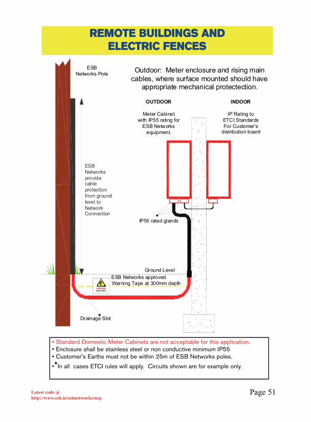
Page 51Latest code @http://www.esb.ie/esbnetworks/ncp
RREEMMOOTTEE BBUUIILLDDIINNGGSS AANNDDEELLEECCTTRRIICC FFEENNCCEESS
ESBNetworks Pole
WARNINGELEC TRI CI TY SUPP LY C ABLE DU CT BELO W
Ground Level
INDOOR
IP Rating toETCI Standards For Customer's
distribution board
OUTDOOR
Meter Cabinetwith IP55 rating for
ESB Networks equipment.
IP55 rated glands
Outdoor: Meter enclosure and rising main cables, where surface mounted should have
appropriate mechanical protectection.
Drainage Slot
ESB Networks provide cable protection from ground level to Network Connection
ESB Networks approved Warning Tape at 300mm depth
• Standard Domestic Meter Cabinets are not acceptable for this application.• Enclosure shall be stainless steel or non conductive minimum IP55• Customer’s Earths must not be within 25m of ESB Networks poles.
•*In all cases ETCI rules will apply. Circuits shown are for example only.

Page 52Latest code @http://www.esb.ie/esbnetworks/ncp
IInn ggeenneerraall aallll iinnssttaallllaattiioonnss ccoonnnneecctteedd ttoo EESSBB NNeettwwoorrkkss aarreemmeetteerreedd..
There are, however, situations where this does not apply. Single phaseloads not exceeding 2kVA will be considered for unmeteredconnections. At application stage ESB Networks will decide if theconnection is to be metered or unmetered.
The majority of special situation un-metered connections are for free-standing street furniture (bus shelters, phone kiosks, traffic controls,signs etc). The drawing below shows the typical connection sequencefor such installations. For preferred interface options see matrix onpage 53.
SSPPEECCIIAALL SSIITTUUAATTIIOONNSSFFUUNNDDAAMMEENNTTAALL RREEQQUUIIRREEMMEENNTTSS AATT TTHHEE
CCUUSSTTOOMMEERR IINNTTEERRFFAACCEE
ESB Networks Cut-Out
Switch Fuse30mA RCD
Where required 3 Core SWAESB
Networks Connection
Earth RodEnclosure
ESB Networks Isolator
ESB Networks CUSTOMER
• Some situations require the installation of RCDs.• In all cases ETCI rules will apply. Circuits shown are for example only

Page 53Latest code @http://www.esb.ie/esbnetworks/ncp
The list below shows the preferred option and acceptable alternatives.See page 52 for electrical circuit requirements.
TTYYPPIICCAALL AAPPPPLLIICCAATTIIOONNSS OOFF SSPPEECCIIAALLSSIITTUUAATTIIOONNSS LLAAYYOOUUTT
Type of installation Page 54 Page 55 Page 56Advertising HoardingAdvertising KiosksBus SheltersGarda Cameras (CCTV)Ice Detecting StationsSchool SignsTelephone KioskTraffic Counting StationsTV BoosterWater Metering Points
Type of installation Page 57Festive LightingMobile Comms. SitesSewage PumpingWater Pumping
UnmeteredMetered Page 62
Unmetered
Metered
Public Lighting Unmetered/MeteredPages 58 - 61
= Preferred Option = Other Options
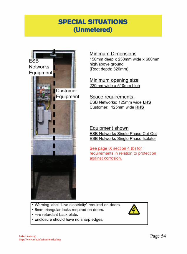
Page 54Latest code @http://www.esb.ie/esbnetworks/ncp
SSPPEECCIIAALL SSIITTUUAATTIIOONNSS ((UUnnmmeetteerreedd))
Minimum Dimensions150mm deep x 250mm wide x 600mmhigh/above ground(Root depth: 320mm)
Minimum opening size220mm wide x 510mm high
Space requirements ESB Networks: 125mm wide LHSCustomer: 125mm wide RHS
Equipment shownESB Networks Single Phase Cut OutESB Networks Single Phase Isolator
See page lX section 4 (b) forrequirements in relation to protectionagainst corrosion.
• Warning label “Live electricity” required on doors.• 8mm triangular locks required on doors.• Fire retardant back plate.• Enclosure should have no sharp edges.
ESBNetworksEquipment
CustomerEquipment
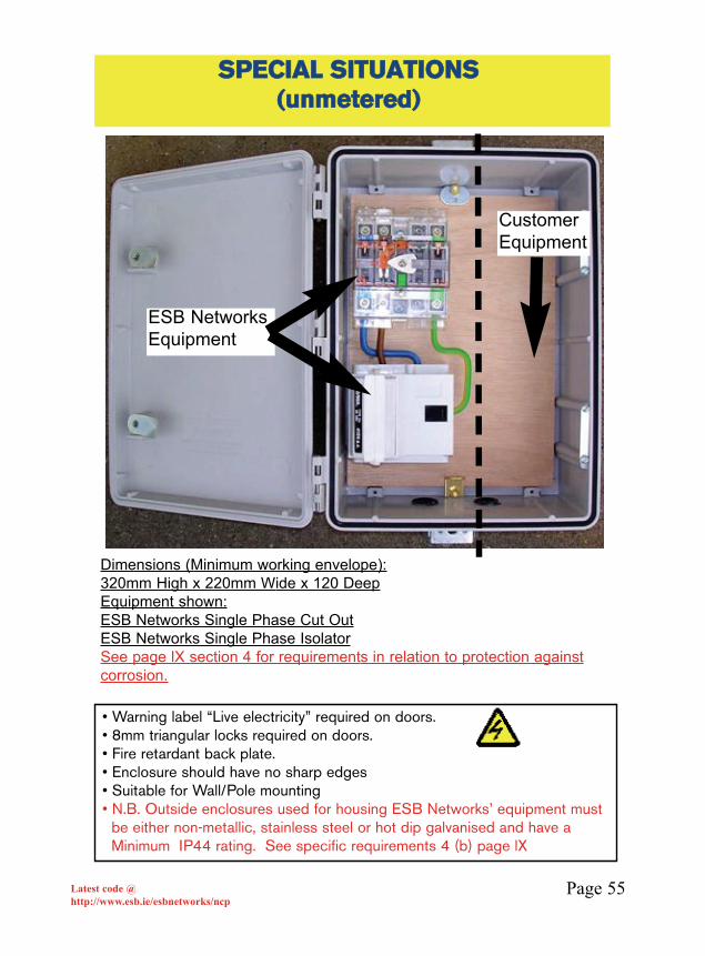
Page 55Latest code @http://www.esb.ie/esbnetworks/ncp
SSPPEECCIIAALL SSIITTUUAATTIIOONNSS ((uunnmmeetteerreedd))
• Warning label “Live electricity” required on doors.• 8mm triangular locks required on doors.• Fire retardant back plate.• Enclosure should have no sharp edges• Suitable for Wall/Pole mounting• N.B. Outside enclosures used for housing ESB Networks’ equipment must
be either non-metallic, stainless steel or hot dip galvanised and have a Minimum IP44 rating. See specific requirements 4 (b) page lX
CustomerEquipment
ESB NetworksEquipment
Dimensions (Minimum working envelope):320mm High x 220mm Wide x 120 DeepEquipment shown:ESB Networks Single Phase Cut OutESB Networks Single Phase IsolatorSee page lX section 4 for requirements in relation to protection againstcorrosion.

Page 56Latest code @http://www.esb.ie/esbnetworks/ncp
SSPPEECCIIAALL SSIITTUUAATTIIOONNSS ((UUnnmmeetteerreedd))
• Warning label “Live electricity” required on doors.• Suitable for underground connections for use with cable vault.• The Photograph shows an IP67 enclosure.• Note the use of glands to maintain IP rating of cable entries• N.B. Outside enclosures used for housing ESB Networks’ equipment must
be either non-metallic, stainless steel or hot dip galvanised and have a Minimum IP44 rating. See specific requirements 4 (b) page lX
ESBNetworksEquipment
CustomerEquipment
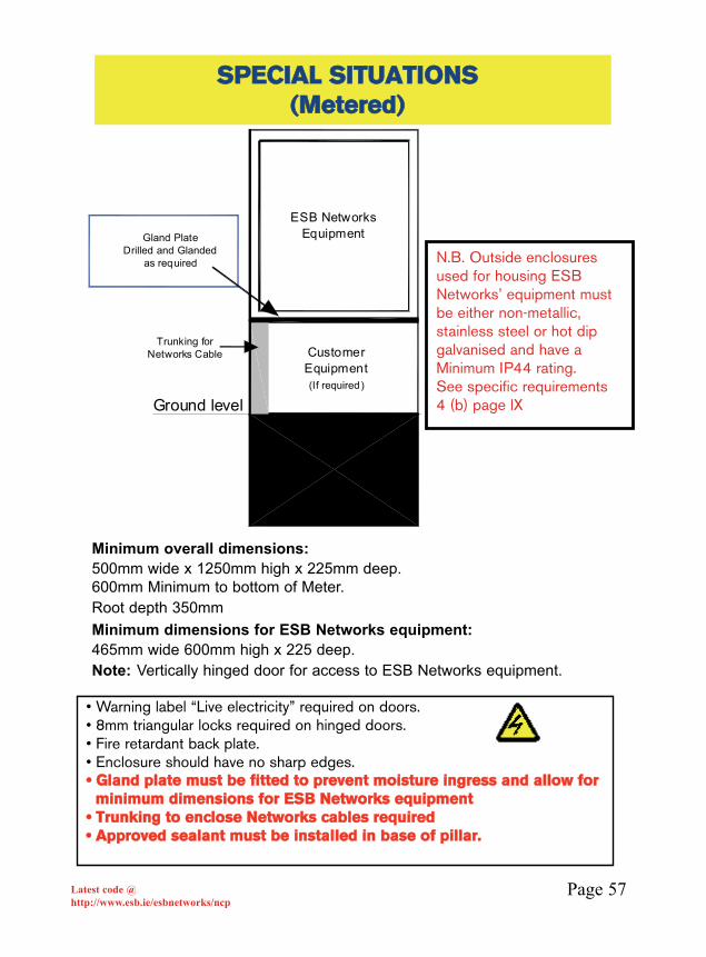
Page 57Latest code @http://www.esb.ie/esbnetworks/ncp
SSPPEECCIIAALL SSIITTUUAATTIIOONNSS ((MMeetteerreedd))
• Warning label “Live electricity” required on doors.• 8mm triangular locks required on hinged doors.• Fire retardant back plate.• Enclosure should have no sharp edges.•• GGllaanndd ppllaattee mmuusstt bbee ffiitttteedd ttoo pprreevveenntt mmooiissttuurree iinnggrreessss aanndd aallllooww ffoorr
mmiinniimmuumm ddiimmeennssiioonnss ffoorr EESSBB NNeettwwoorrkkss eeqquuiippmmeenntt•• TTrruunnkkiinngg ttoo eenncclloossee NNeettwwoorrkkss ccaabblleess rreeqquuiirreedd•• AApppprroovveedd sseeaallaanntt mmuusstt bbee iinnssttaalllleedd iinn bbaassee ooff ppiillllaarr..
ESB NetworksEquipment
CustomerEquipment(If required)
Ground level
Trunking for Networks Cable
Gland PlateDrilled and Glanded
as required
Minimum overall dimensions:500mm wide x 1250mm high x 225mm deep.600mm Minimum to bottom of Meter. Root depth 350mmMinimum dimensions for ESB Networks equipment:465mm wide 600mm high x 225 deep.Note: Vertically hinged door for access to ESB Networks equipment.
N.B. Outside enclosures used for housing ESB Networks’ equipment must be either non-metallic, stainless steel or hot dip galvanised and have a Minimum IP44 rating. See specific requirements 4 (b) page lX

Page 58Latest code @http://www.esb.ie/esbnetworks/ncp
SSPPEECCIIAALL SSIITTUUAATTIIOONNSS PPUUBBLLIICC LLIIGGHHTTIINNGG
Customers Main Fuse (25 Amp16kA Breaking capacity)
Main Protective Conductor
Protective earth connectedto frame of Service pillar
Main Earth Terminal
ESB Networks Standard Cut-out
Earth Electrode
N
Cable to columnConnection from ESB Networks Mini-pillar
In all situations, ESB Networks cable will terminate in ESB Networks Cut Out. Service size will be appropriate to customer's requested Maximum Import Capicity.
ESB Networks Isolator
TThheerree sshhoouulldd bbee aa sseeppaarraattiioonn ooff aatt lleeaasstt 22 mmeettrreessbbeettwweeeenn tthhee EESSBB NNeettwwoorrkkss mmiinnii ppiillllaarr aanndd tthhee
ccuussttoommeerr’’ss sseerrvviiccee ppiillllaarr
The purpose of this requirement is to avoid conflict and ensure segregation betweenthe ESB Networks cable vault/ducts and the public lighting ducting e.g. the publiclighting circuits cannot pass through the mini pillar cable vault.
Note: This distance may be reduced if segregation is ensured. In thissituation the mini pillar and customer’s service pillar must be cross bonded.
•• IInn aallll ccaasseess EETTCCII RRuulleess wwiillll aappppllyy.. CCiirrccuuiittss sshhoowwnn aarree ffoorr eexxaammppllee oonnllyy..
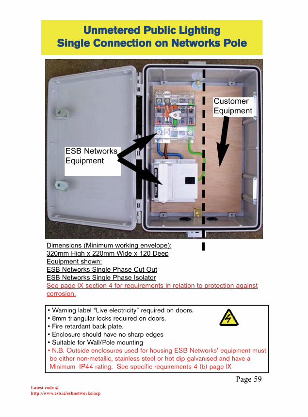
Latest code @http://www.esb.ie/esbnetworks/ncp
UUnnmmeetteerreedd PPuubblliicc LLiigghhttiinngg SSiinnggllee CCoonnnneeccttiioonn oonn NNeettwwoorrkkss PPoollee
• Warning label “Live electricity” required on doors.• 8mm triangular locks required on doors.• Fire retardant back plate.• Enclosure should have no sharp edges• Suitable for Wall/Pole mounting• N.B. Outside enclosures used for housing ESB Networks’ equipment mustbe either non-metallic, stainless steel or hot dip galvanised and have aMinimum IP44 rating. See specific requirements 4 (b) page lX
Dimensions (Minimum working envelope):320mm High x 220mm Wide x 120 DeepEquipment shown:ESB Networks Single Phase Cut OutESB Networks Single Phase IsolatorSee page lX section 4 for requirements in relation to protection againstcorrosion.
Page 59
ESB NetworksEquipment
CustomerEquipment

Latest code @http://www.esb.ie/esbnetworks/ncp
UUnnmmeetteerreedd PPuubblliicc LLiigghhttiinnggSSiinnggllee PPhhaassee PPiillllaarr
Minimum Dimensions150mm deep x 250mm wide x 600mmhigh/above ground(Root depth: 320mm)
Minimum opening size220mm wide x 510mm high
Space requirements ESB Networks: 125mm wide LHSCustomer: 125mm wide RHS
Equipment shownESB Networks Single Phase Cut OutESB Networks Single Phase Isolator
See page lX section 4 (b) forrequirements in relation to protectionagainst corrosion.
• Warning label “Live electricity” required on doors.• 8mm triangular locks required on doors.• Fire retardant back plate.• Enclosure should have no sharp edges.
ESBNetworksEquipment
CustomerEquipment
Page 60
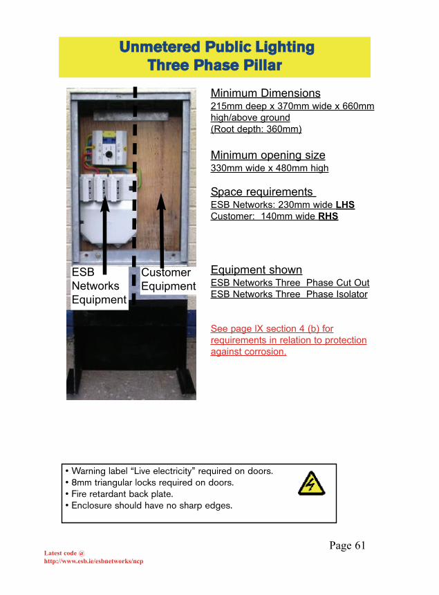
Latest code @http://www.esb.ie/esbnetworks/ncp
UUnnmmeetteerreedd PPuubblliicc LLiigghhttiinnggTThhrreeee PPhhaassee PPiillllaarr
• Warning label “Live electricity” required on doors.• 8mm triangular locks required on doors.• Fire retardant back plate.• Enclosure should have no sharp edges.
Minimum Dimensions215mm deep x 370mm wide x 660mmhigh/above ground(Root depth: 360mm)
Minimum opening size330mm wide x 480mm high
Space requirements ESB Networks: 230mm wide LHSCustomer: 140mm wide RHS
Equipment shownESB Networks Three Phase Cut OutESB Networks Three Phase Isolator
See page lX section 4 (b) forrequirements in relation to protectionagainst corrosion.
ESBNetworksEquipment
CustomerEquipment
Page 61
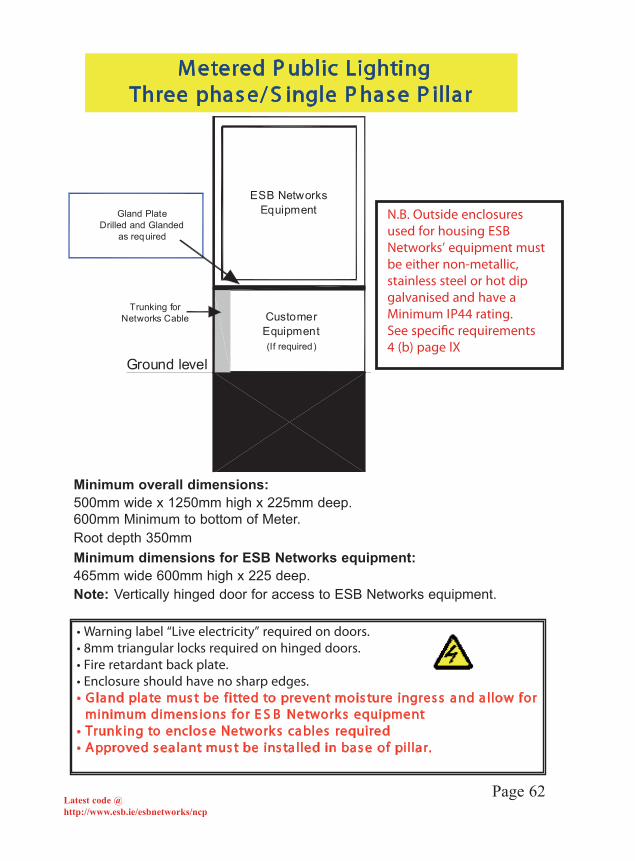
Latest code @http://www.esb.ie/esbnetworks/ncp
M etered P ublic LightingThree phas e/ S ingle P has e P illar
ESB NetworksEquipment
CustomerEquipment(If required)
Ground level
Trunking for Networks Cable
Gland PlateDrilled and Glanded
as required
• Warning label “Live electricity” required on doors.• 8mm triangular locks required on hinged doors.• Fire retardant back plate.• Enclosure should have no sharp edges.• G land plate mus t be fitted to prevent mois ture ingres s and a llow for
minimum dimens ions for E S B Network s equipment• Trunk ing to enclos e Network s cables required• Approved s ealant mus t be ins ta lled in bas e of pillar.
Page 62
Minimum overall dimensions:500mm wide x 1250mm high x 225mm deep.600mm Minimum to bottom of Meter. Root depth 350mmMinimum dimensions for ESB Networks equipment:465mm wide 600mm high x 225 deep.Note: Vertically hinged door for access to ESB Networks equipment.
N.B. Outside enclosures used for housing ESB Networks’ equipment must be either non-metallic, stainless steel or hot dip galvanised and have a Minimum IP44 rating. See speci�c requirements 4 (b) page lX

Page 63Latest code @http://www.esb.ie/esbnetworks/ncp
In processing the application for connection the ESB Networks will, inconsultation with the customer, specify the voltage level of the connection
NNeeww llooaaddss iinn eexxcceessss ooff 550000kkVVAA wwiillll iinn ggeenneerraall bbee ssuupppplliieedd aatt MMeeddiiuummVVoollttaaggee.. MMeeddiiuumm VVoollttaaggee rreeffeerrss ttoo 1100kkVV//2200kkVV.. TThhiiss ddooccuummeenntt rreeffeerrss ttootthhee ssttaannddaarrdd ccoonnnneeccttiioonn rreeqquuiirreemmeennttss ffoorr 1100kkVV//2200kkVV..
If connection is to be made available at MV the following information willfacilitate the consultant / customer in pursuing the application for connection.
• The customer’s installation must comply with current S.I. requirements.
• ETCI requirements shall prevail.
• ESB Networks Specification 13320 “General Specification for MVsubstation”. (available from ESB Networks)
• ESB Networks document: “Conditions Governing Connection to theDistribution System for Medium Voltage Connections.” (available from ESBNetworks)
• ESB Networks Document “Medium Voltage - Dual Radial Supply.”(available from ESB Networks)
The above ESB Networks documents list out ESB Networks requirementsrelating to MV customers. In addition, please see required procedures onfollowing pages.
RREEQQUUIIRREEMMEENNTTSS FFOORR CCOONNNNEECCTTIIOONNAATT MMEEDDIIUUMM VVOOLLTTAAGGEE ((MMVV))
Page 64Latest code @http://www.esb.ie/esbnetworks/ncp
PPRROOCCEEDDUURREE::
AA mmeeeettiinngg ttoo ccoo--oorrddiinnaattee aarrrraannggeemmeennttss ffoorr eenneerrggiissiinngg tthhee ccoonnnneeccttiioonnsshhaallll ttaakkee ppllaaccee aatt lleeaasstt 55 wwoorrkkiinngg ddaayyss bbeeffoorree ccoonnnneeccttiioonn iiss rreeqquuiirreedd..CCoonnttrraaccttoorrss iinnvvoollvveedd iinn tthhee ccoonnssttrruuccttiioonn aanndd ccoommmmiissssiioonniinngg ooff tthhee MMVVeeqquuiippmmeenntt sshhaallll bbee rreepprreesseenntteedd aatt tthhiiss mmeeeettiinngg..
The following shall be provided to ESB Networks at least two working daysbefore energisation is required :
(a) Primary and Secondary Test Sheets for the Main Incomer Circuit Breakers Protection Relays .PPrriimmaarryy tteessttss ttoo bbee ccoommpplleetteedd oonn ssiittee..
(b) Confirmation of customers protection relay settings controlling the main incomer circuit breaker. (as specified by local ESB Networks Designoffice in terms for supply)
(c) Details of ratio of customer's protection CTs and protection relay type.(d) Earthing has been installed as per requirements(e) ETCI Completion Certificate. (f) A declaration of fitness certificate for the MV installation that is to be
connected to the ESB Networks MV system.TThhiiss wwiillll nnoorrmmaallllyy bbee tthhee ffiinnaall ddooccuummeenntt ggiivveenn ttoo EESSBB NNeettwwoorrkkssiimmmmeeddiiaatteellyy bbeeffoorree tthhee ccoonnnneeccttiioonn iiss eenneerrggiisseedd,, and shall statethat the proposed MV system is fit for service from a safety, technicaland operations perspective.
OOPPEERRAATTIIOONN
In the interests of safety, access to the customer's medium voltage switch room shall be restricted to competent personnel only. Operation and maintenance of the customer's equipment shall be carried out by fully trained and competent personnel.The customer's switch panel shall indicate clearly the connection sequence of all equipment connected to it.A durable Single Line Diagram shall be mounted in the customer's switch room in a prominent location. Operating procedures shall be agreed between local ESB Networks and customer.
RREEQQUUIIRREEMMEENNTTSS FFOORR CCOONNNNEECCTTIIOONNAATT MMEEDDIIUUMM VVOOLLTTAAGGEE ((MMVV))

Page 65Latest code @http://www.esb.ie/esbnetworks/ncp
EESSBB NNEETTWWOORRKKSS EEAARRTTHHIINNGG RREEQQUUIIRREEMMEENNTTSS
Earthing facility required on main incomer cable.
CCAABBLLEE TTEERRMMIINNAATTIIOONNSS
The main incoming terminals to the circuit breaker shall be suitable forterminating three single core cables, XLPE insulated and black PE(polyethylene) sheath overall.
Customers shall confirm with ESB Networks the configuration and sizeapplicable to their particular installation.
The customer or his agent shall provide suitable terminating kits for connectionof the above cables to the main incoming terminals of the circuit breaker.
Adequate space shall be provided in the customer’s switch room to enableESB Networks staff to work on cable terminations.
MMEETTEERRIINNGG
Space shall be provided for the MD Metering Cabinet as indicated by ESBNetworks
LLAABBEELLLLIINNGGThe main incoming circuit breaker must have a permanent label affixed.
NOTE: There must be no possibility of interchanging incoming andoutgoing circuit labels.
RREEQQUUIIRREEMMEENNTTSS FFOORR CCOONNNNEECCTTIIOONNAATT MMEEDDIIUUMM VVOOLLTTAAGGEE ((MMVV))
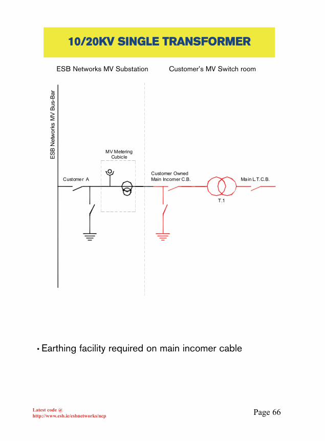
Page 66Latest code @http://www.esb.ie/esbnetworks/ncp
1100//2200KKVV SSIINNGGLLEE TTRRAANNSSFFOORRMMEERR
MV Metering Cubicle
Customer Owned Main Incomer C.B.Customer A
T.1
Main L.T.C.B.
ESB
Net
wor
ks M
V Bu
s-Ba
r
ESB Networks MV Substation Customer’s MV Switch room
• Earthing facility required on main incomer cable
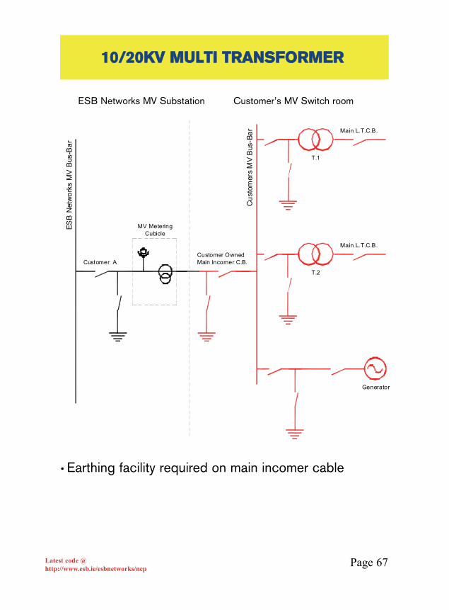
Page 67Latest code @http://www.esb.ie/esbnetworks/ncp
1100//2200KKVV MMUULLTTII TTRRAANNSSFFOORRMMEERR
MV Metering Cubicle
Customer Owned Main Incomer C.B.
T.1
Main L.T.C.B.
Customer A
T.2
Main L.T.C.B.
Generator
Cus
tom
ers
MV
Bus
-Bar
ESB
Net
wor
ks M
V B
us-B
ar
ESB Networks MV Substation Customer’s MV Switch room
• Earthing facility required on main incomer cable
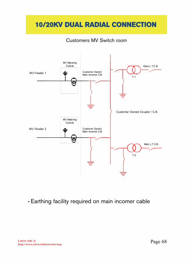
Page 68Latest code @http://www.esb.ie/esbnetworks/ncp
1100//2200KKVV DDUUAALL RRAADDIIAALL CCOONNNNEECCTTIIOONN
MV Metering Cubicle
Customer Owned Main Incomer C.B.
T.1
Main L.T.C.B.
T.2
Main L.T.C.B.
MV Metering Cubicle
Customer Owned Main Incomer C.B.MV Feeder 1
MV Feeder 2
Customer Owned Coupler / C.B.
Customers MV Switch room
• Earthing facility required on main incomer cable
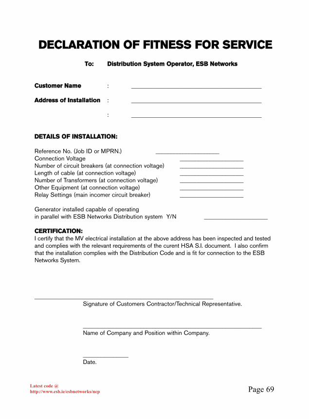
Page 69Latest code @http://www.esb.ie/esbnetworks/ncp
DDEECCLLAARRAATTIIOONN OOFF FFIITTNNEESSSS FFOORR SSEERRVVIICCEE
TToo:: DDiissttrriibbuuttiioonn SSyysstteemm OOppeerraattoorr,, EESSBB NNeettwwoorrkkss
CCuussttoommeerr NNaammee : ___________________________________________
AAddddrreessss ooff IInnssttaallllaattiioonn : ___________________________________________
: ___________________________________________
DDEETTAAIILLSS OOFF IINNSSTTAALLLLAATTIIOONN::
Reference No. (Job ID or MPRN.) _____________________Connection Voltage _____________________Number of circuit breakers (at connection voltage) _____________________Length of cable (at connection voltage) _____________________Number of Transformers (at connection voltage) _____________________Other Equipment (at connection voltage) _____________________Relay Settings (main incomer circuit breaker) _____________________
Generator installed capable of operating in parallel with ESB Networks Distribution system Y/N _____________________
CCEERRTTIIFFIICCAATTIIOONN::I certify that the MV electrical installation at the above address has been inspected and testedand complies with the relevant requirements of the curent HSA S.I. document. I also confirmthat the installation complies with the Distribution Code and is fit for connection to the ESBNetworks System.
___________________________________________________________Signature of Customers Contractor/Technical Representative.
___________________________________________________________Name of Company and Position within Company.
_______________Date.

Page 70Latest code @http://www.esb.ie/esbnetworks/ncp
The following additional pages have been included inthese appendices in order to amplify the informationappearing in the main body of the code.
Appendix A: Typical design for installing a standard meteringenclosureAppendix B: Standard design for surface mounted meteringenclosure on concrete plinthAppendix C: Instructions for installation of commercialtemporary supply.Appendix D: Instructions for installation of customer’s mainovercurrent device if mounted in standard outside cabinet.Appendix E and F: ESB Networks contact numbersAppendix G and H: ESB Networks AREAS/DIVISIONS
AADDDDIITTIIOONNAALL UUSSEEFFUULL IINNFFOORRMMAATTIIOONN
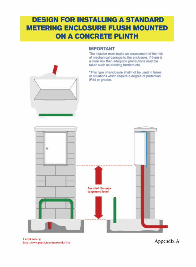
Appendix ALatest code @http://www.presb.ie/esbnetworks/ncp
DDEESSIIGGNN FFOORR IINNSSTTAALLLLIINNGG AA SSTTAANNDDAARRDDMMEETTEERRIINNGG EENNCCLLOOSSUURREE FFLLUUSSHH MMOOUUNNTTEEDD
OONN AA CCOONNCCRREETTEE PPLLIINNTTHH

Appendix BLatest code @http://www.presb.ie/esbnetworks/ncp
DDEESSIIGGNN FFOORR SSUURRFFAACCEE MMOOUUNNTTEEDDMMEETTEERRIINNGG EENNCCLLOOSSUURREE OONN AA CCOONNCCRREETTEE PPLLIINNTTHH
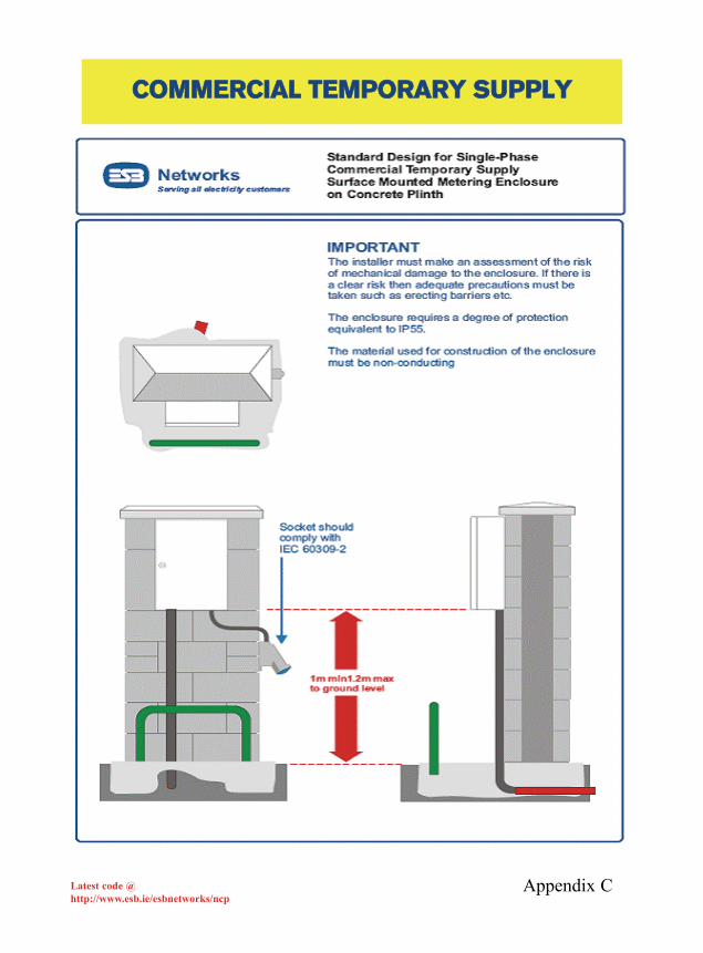
Appendix CLatest code @http://www.esb.ie/esbnetworks/ncp
CCOOMMMMEERRCCIIAALL TTEEMMPPOORRAARRYY SSUUPPPPLLYY

MMAAIINN OOVVEERRCCUURRRREENNTT DDEEVVIICCEE MMOOUUNNTTEEDDIINN SSTTAANNDDAARRDD MMEETTEERR CCAABBIINNEETT
NN..BB.. If the main overcurrent device is located within the standard meter cabinet, it shall comply with the following requirements:
• In the case of installations with a maximum import capacity of less than 50kVA an MCBrated not less than 63A and having a multiple-operation short circuit breaking capacity of at least 9kA rms.
• The MCB shall be housed in an non conducting (self extinguishing 750º C) weatherproof enclosure rated IP55 min.
• A hinged transparent cover (IP55 min) shall give access for operating the MCB but noaccess to live terminals without the use of a tool.
• The enclosure shall be mounted only in the bottom right hand side of the meter cabinet as shown above to allow the further possibility of mounting additional equipment by the DSO as the need may arise.
• In all cases ETCI rules will apply.
Appendix DLatest code @http://www.esb.ie/esbnetworks/ncp

Appendix ELatest code @http://www.esb.ie/esbnetworks/ncp
EESSBB NNEETTWWOORRKKSS CCOONNTTAACCTT NNUUMMBBEERRSS
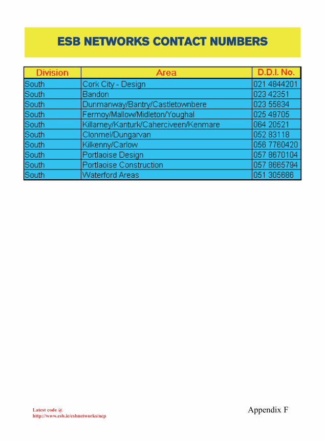
Appendix FLatest code @http://www.esb.ie/esbnetworks/ncp
EESSBB NNEETTWWOORRKKSS CCOONNTTAACCTT NNUUMMBBEERRSS
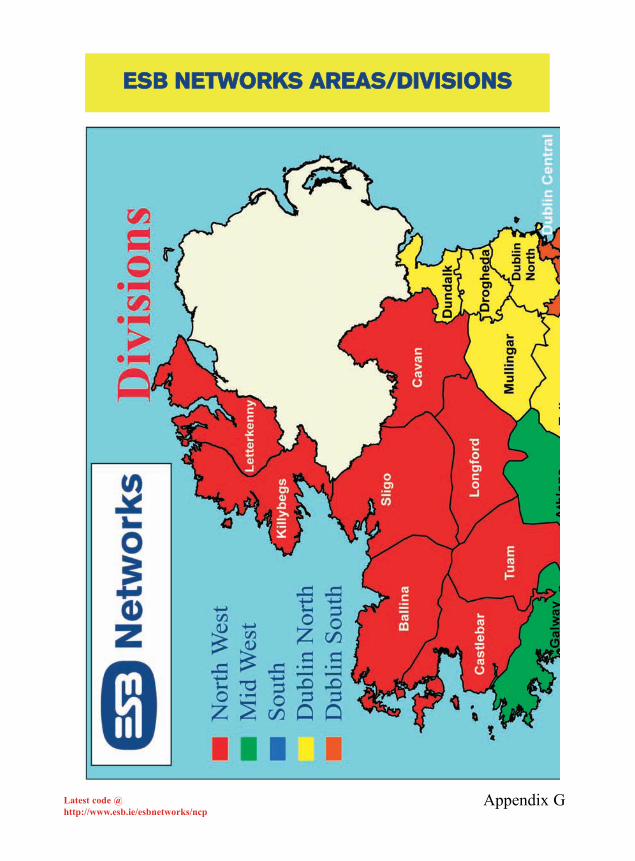
Appendix GLatest code @http://www.esb.ie/esbnetworks/ncp
EESSBB NNEETTWWOORRKKSS AARREEAASS//DDIIVVIISSIIOONNSS
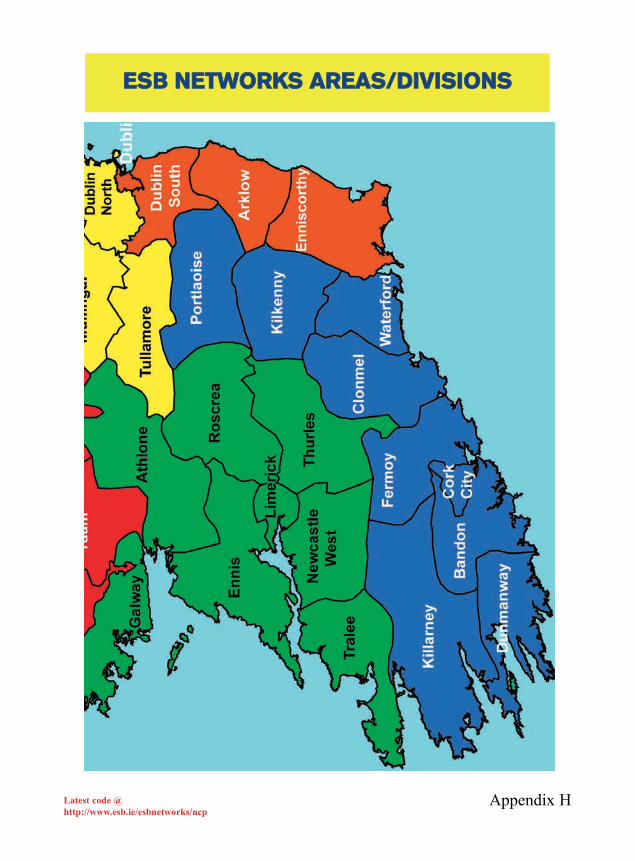
Appendix HLatest code @http://www.esb.ie/esbnetworks/ncp
EESSBB NNEETTWWOORRKKSS AARREEAASS//DDIIVVIISSIIOONNSS