ESA601 - Fluke Corporationassets.fluke.com/manuals/ESA601__omeng0100.pdfCertification This...
96
ESA601 Electrical Safety Analyzer Operators Manual November 2004, Rev. 1, 12/05 © 2004-2005 Fluke Corporation, All rights reserved. All product names are trademarks of their respective companies.
Transcript of ESA601 - Fluke Corporationassets.fluke.com/manuals/ESA601__omeng0100.pdfCertification This...

ESA601 Electrical Safety Analyzer
Operators Manual
November 2004, Rev. 1, 12/05 © 2004-2005 Fluke Corporation, All rights reserved. All product names are trademarks of their respective companies.

Warranty
Warranty and Product Support Fluke Biomedical warrants this instrument against defects in materials and workmanship for one full year from the date of original purchase. During the warranty period, we will repair or, at our option, replace at no charge a product that proves to be defective, provided you return the product, shipping prepaid, to Fluke Biomedical. This warranty does not apply if the product has been damaged by accident or misuse or as the result of service or modification by other than Fluke Biomedical. IN NO EVENT SHALL FLUKE BIOMEDICAL BE LIABLE FOR CONSEQUENTIAL DAMAGES. Only serialized products and their accessory items (those products and items bearing a distinct serial number tag) are covered under this one–year warranty. PHYSICAL DAMAGE CAUSED BY MISUSE OR PHYSICAL ABUSE IS NOT COVERED UNDER THE WARRANTY. Items such as cables and nonserialized modules are not covered under this warranty. Recalibration of instruments is not covered under the warranty. This warranty gives you specific legal rights, and you may also have other rights which vary from state to state, province to province, or country to country. This warranty is limited to repairing the instrument to Fluke Biomedical’s specifications.
Warranty Disclaimer Should you elect to have your instrument serviced and/or calibrated by someone other than Fluke Biomedical, please be advised that the original warranty covering your product becomes void when the tamper-resistant Quality Seal is removed or broken without proper factory authorization. We strongly recommend, therefore, that you send your instrument to Fluke Biomedical for factory service and calibration, especially during the original warranty period. In all cases, breaking the tamper-resistant Quality Seal should be avoided at all cost, as this seal is the key to your original instrument warranty. In the event that the seal must be broken to gain internal access to the instrument, you must first contact Fluke Biomedical’s Technical Assistance Department at 775-883-3400. You will be required to provide the serial number for your instrument as well as a valid reason for breaking the Quality Seal. You should break this seal only after you have received factory authorization. Do not break the Quality Seal before you have contacted us. Following these steps will help ensure that you will retain the original warranty on your instrument without interruption.

Notices
All Rights Reserved Copyright 2004, Fluke Biomedical. No part of this publication may be reproduced, transmitted, transcribed, stored in a retrieval system, or translated into any language without the written permission of Fluke Biomedical.
Copyright Release Fluke Biomedical agrees to a limited copyright release that allows you to reproduce manuals and other printed materials for use in service training programs and other technical publications. If you would like other reproductions or distributions, submit a written request to Fluke Biomedical.
Unpacking and Inspection Follow standard receiving practices upon receipt of the instrument. Check the shipping carton for damage. If damage is found, stop unpacking the instrument. Notify the carrier and ask for an agent to be present while the instrument is unpacked. There are no special unpacking instructions, but be careful not to damage the instrument when unpacking it. Inspect the instrument for physical damage such as bent or broken parts, dents, or scratches.
Claims Our routine method of shipment is via common carrier, FOB origin. Upon delivery, if physical damage is found, retain all packing materials in their original condition and contact the carrier immediately to file a claim. If the instrument is delivered in good physical condition but does not operate within specifications, or if there are any other problems not caused by shipping damage, please contact Fluke Biomedical or your local sales representative.
Standard Terms and Conditions Refunds and Credits
Please note that only serialized products and their accessory items (i.e., products and items bearing a distinct serial number tag) are eligible for partial refund and/or credit. Nonserialized parts and accessory items (e.g., cables, carrying cases, auxiliary modules, etc.) are not eligible for return or refund. Only products returned within 90 days from the date of original purchase are eligible for refund/credit. In order to receive a partial refund/credit of a product purchase price on a serialized product, the product must not have been damaged by the customer or by the carrier chosen by the customer to return the goods, and the product must be returned complete (meaning with all manuals, cables, accessories, etc.) and in “as new” and resalable condition. Products not returned within 90 days of purchase, or products which are not in “as new” and resalable condition, are not eligible for credit return and will be returned to the customer. The Return Procedure (see below) must be followed to assure prompt refund/credit.
Restocking Charges Products returned within 30 days of original purchase are subject to a minimum restocking fee of 15 %. Products returned in excess of 30 days after purchase, but prior to 90 days, are subject to a minimum restocking fee of 20 %. Additional charges for damage and/or missing parts and accessories will be applied to all returns.
Return Procedure All items being returned (including all warranty-claim shipments) must be sent freight-prepaid to our factory location. When you return an instrument to Fluke Biomedical, we recommend using United Parcel Service, Federal Express, or Air Parcel Post. We also recommend that you insure your shipment for its actual replacement cost. Fluke Biomedical will not be responsible for lost shipments or instruments that are received in damaged condition due to improper packaging or handling. Use the original carton and packaging material for shipment. If they are not available, we recommend the following guide for repackaging:
Use a double–walled carton of sufficient strength for the weight being shipped. Use heavy paper or cardboard to protect all instrument surfaces. Use nonabrasive material around all projecting parts. Use at least four inches of tightly packed, industry-approved, shock-absorbent material around the instrument.
Returns for partial refund/credit: Every product returned for refund/credit must be accompanied by a Return Material Authorization (RMA) number, obtained from our Customer Service Department:
Customer Service Fluke Biomedical 800-648-7952 (USA) or 775-883-3400.
Returns for service/repair/calibration: In order to expedite service, please schedule a repair or calibration by calling 888-99FLUKE (888-993-5853) to obtain an RMA # prior to sending the equipment. For international customers, please email [email protected] to obtain this RMA #. Ship the instrument, freight-prepaid and fully insured, to the following address:
Fluke Customer Service Center 1420 – 75th Street SW Everett, WA 98203

Certification This instrument was thoroughly tested and inspected. It was found to meet Fluke Biomedical’s manufacturing specifications when it was shipped from the factory. Calibration measurements are traceable to the National Institute of Standards and Technology (NIST). Devices for which there are no NIST calibration standards are measured against in-house performance standards using accepted test procedures.
WARNING Unauthorized user modifications or application beyond the published specifications may result in electrical shock hazards or improper operation. Fluke Biomedical will not be responsible for any injuries sustained due to unauthorized equipment modifications.
Restrictions and Liabilities Information in this document is subject to change and does not represent a commitment by Fluke Biomedical. Changes made to the information in this document will be incorporated in new editions of the publication. No responsibility is assumed by Fluke Biomedical for the use or reliability of software or equipment that is not supplied by Fluke Biomedical, or by its affiliated dealers.
Manufacturing Location The ESA601 Electrical Safety Analyzer is manufactured in Everett, WA, U.S.A.

i
Table of Contents
Chapter Title Page
Standards and Safety................................................................................................vi Applicable Testing Standards ............................................................................vi
USA Class A .............................................................................................vi Canadian Department of Communications Class A..................................vi
EC Directive 89/336/EEC Electromagnetic Compatibility ...........................vi Emissions - Class A ..................................................................................vi Immunity ...................................................................................................vi
EC Directive 73/23/EEC Low Voltage .........................................................vii User Safety ................................................................................................vii
Safety Considerations ........................................................................................vii
1 General Information ............................................................................ 1-1 Introduction to the ESA601 ...............................................................................1-3 ESA601 Package Contents ................................................................................1-3
ESA601 Electrical Safety Analyzer ..............................................................1-3 Standard Accessories.....................................................................................1-4 Optional Accessories .....................................................................................1-4 Unpacking the ESA601 .................................................................................1-5 Storage and Maintenance ..............................................................................1-5
ESA Characteristics ...........................................................................................1-6 Top and Side Panels ......................................................................................1-6 Back Panel .....................................................................................................1-9 Date of Manufacture......................................................................................1-10
2 Setting Up the ESA601........................................................................ 2-1 Powering Up the ESA601..................................................................................2-3 Support...............................................................................................................2-3
3 Using the Printer ................................................................................. 3-1 Selecting Language Options ..............................................................................3-3 Selecting the Printer Output...............................................................................3-3 Printing Electrical Safety Test Results ..............................................................3-3

ESA601 Operators Manual
ii
4 Testing Devices ................................................................................... 4-1 Connecting the Device Under Test ....................................................................4-3 Selecting the Test Load......................................................................................4-3 Testing Device Types ........................................................................................4-4
Permanently Wired Devices ..........................................................................4-4 Portable Devices Located in Isolated Power Systems...................................4-4 Three-Phase Portable Devices .......................................................................4-4
5 Local Control ....................................................................................... 5-1 Mode Control.....................................................................................................5-3 Function Selection .............................................................................................5-3 Performing Electrical-Safety Tests ....................................................................5-9
Mains-Voltage Test .......................................................................................5-9 Protective-Earth-Resistance Test...................................................................5-10 Mains-Insulation-Resistance Test..................................................................5-12 Applied-Parts-Insulation-Resistance Test .....................................................5-13 Earth-Leakage-Current Test ..........................................................................5-14 Enclosure-Leakage-Current Test ...................................................................5-16 Patient-Leakage-Current Test........................................................................5-18 Patient-Auxiliary-Leakage-Current Test .......................................................5-20 Mains-On-Applied-Parts-Leakage-Current Test ...........................................5-22 VDE: Equivalent-Device-Leakage-Current Test...........................................5-24 VDE: Equivalent-Patient-Leakage-Current Test...........................................5-26 VDE: Differential-Leakage-Current Test ......................................................5-28 Dual-Lead-Leakage-Current Test..................................................................5-29 Dual-Lead-Voltage Test ................................................................................5-30
6 Remote Control ................................................................................... 6-1 Using Remote Control .......................................................................................6-3
Setup Requirements.......................................................................................6-3 Ansur ESA601 Plug-In Software Introduction..............................................6-3 Sending Commands from the Host Computer...............................................6-4
Remote Control Commands...............................................................................6-4
7 Operator Messages and Service........................................................ 7-1 Error Codes ........................................................................................................7-3
Power-up Error Codes ...................................................................................7-3 Start Up Diagnostic Error Codes ...................................................................7-3
Service ...............................................................................................................7-4
Appendices A Specifications.................................................................................................A-1 B Sample ESA601 Test Printouts ......................................................................B-1 C Equvalent Report Terms.................................................................................C-1 D Abbreviations.................................................................................................D-1

iii
List of Tables
Table Title Page
1-1. ESA601 Electrical Safety Analyzer Versions ........................................................ 1-4 1-2. Top and Side Panel Features .................................................................................. 1-7 1-3. Back Panel Connectors .......................................................................................... 1-10 5-1. Function Selection Switch Positions ...................................................................... 5-3 5-2. Active Switch Settings for Selected Tests.............................................................. 5-7 6-1. Remote Control Commands ................................................................................... 6-4 7-1. Power Up Error Codes ........................................................................................... 7-3 7-2. Sart Up Diagnostice Errors .................................................................................... 7-3 C-1. Language Equivalents for Terms on Report Printouts ........................................... C-1

ESA601 Operators Manual
iv

v
List of Figures
Figure Title Page
1-1. Top and Side Panel Views of the ESA601............................................................. 1-6 1-2. Back Panel View of the ESA601 (IEC) ................................................................. 1-9 1-3. Back Panel View of ESA601 (AAMI) ................................................................... 1-9 4-1. ESA601 Connected to a Device Under Test .......................................................... 4-3 5-1. Protective-Earth-Resistance Test Configuration .................................................... 5-10 5-2. Mains-Insulation-Resistance Test Configuration................................................... 5-12 5-3. Applied-Parts-Insulation-Resistance Test Configuration....................................... 5-13 5-4. Earth-Leakage-Current Test Configuration............................................................ 5-14 5-5. Enclosure-Leakage-Current Test Configuration .................................................... 5-16 5-6. Patient-Leakage-Current Test Configuration ......................................................... 5-18 5-7. Patient-Auxiliary-Leakage-Current Test Configuration ........................................ 5-20 5-8. Mains-On-Applied-Parts-Leakage-Current Test Configuration............................. 5-22 5-9. VDE: Equivalent-Device-Leakage-Current Test Configuration ............................ 5-24 5-10. VDE: Equivlent-Patient-Leakage-Current Test Configuration .............................. 5-26 5-11. VDE: Differential-Leakage-Current Test Configuration ....................................... 5-28 5-12. Dual-Lead-Leakage-Current Test Configuration ................................................... 5-29 5-13. Dual-Lead-Voltage Test Configuration ................................................................. 5-30

ESA601 Operators Manual
vi
Standards and Safety
Applicable Testing Standards Fluke Biomedical's ESA601 Electrical Safety Analyzer (hereafter called the ESA601) has been tested and certified to US and Canadian standards by CSA. The unit conforms to IEC/EN 61010-1 2nd Edition and IEC/EN 61326 and bears the CE mark.
USA Class A
WWARNING W
Warning: Changes or modifications to this unit not expressly approved by the manufacturer could void the user's authority to operate the equipment.
This equipment has been tested and found to comply with the limits for a Class A digital device.
These limits are designed to provide reasonable protection against harmful interference when the equipment is operated in a commercial environment. Like all similar equipment, this equipment generates, uses, and can radiate radio frequency energy, and, if not installed and used in accordance with the instruction manual, may cause harmful interference to radio communications. Operation of this equipment in a residential area is likely to cause interference, in which case the user will be required to correct the interference at his/her own expense.
Canadian Department of Communications Class A
This digital apparatus does not exceed Class A limits for radio emissions from digital apparatus set out in the Radio Interference Regulations of the Canadian Department of Communications.
Le present appareil numerique n'met pas du bruits radioelectriques depassant les limites applicables aux appareils numerique de la Class A prescrites dans le Reglement sur le brouillage radioelectrique edicte par le ministere des Communications du Canada.
Based on the testing standards below,this device bears the mark.
EC Directive 89/336/EEC Electromagnetic Compatibility
Emissions - Class A
The system has been type tested and found to meet the requirements of EN 61326:1997/A1: 1998/A2: 2001 for Radiated Emissions and Line Conducted Emissions.
Immunity
The system has been type tested and found to meet the requirements of EN 61326:1997/A1: 1998/A2: 2001 for Immunity. Verification of compliance was conducted to the limits and methods of the following:
EN 61000-3-2 Harmonics Current Emission EN 61000-3-3 Voltage Fluctuations and Flicker EN 61000-4-2 Electrostatic Discharge EN 61000-4-3 RF Electromagnetic Fields EN 61000-4-4 Fast Transient/Burst EN 61000-4-5 Surge Immunity EN 61000-4-6 RF Common Mode Disturbances EN 61000-4-11 Voltage Dips, Short Interruptions and AC Variations

vii
EC Directive 73/23/EEC Low Voltage
User Safety
The system has been type tested and found to meet the requirements of EC Directive 73/23/EEC for Low Voltage. Verification of compliance was conducted to the limits and methods of the following:
EN 61010-1 (2001) 2nd Edition
“Safety Requirements for Electrical Equipment for Measurement, Control and Laboratory Use, Part 1: General requirements” (including amendments 1 and 2).
Safety Considerations Use of this instrument is restricted to qualified personnel who recognize shock hazards and are familiar with safety precautions used when operating electrical equipment. Read the manual carefully before operating the ESA601. The following warning and informational symbols may be found on the ESA601:
Symbol
Description
Protective-Earth Resistance
Caution (Refer to accompanying documentation.)
Caution Risk of electric shock
ON (Connects power for operation.)
OFF (Disconnects power.)

ESA601 Operators Manual
viii
WXWarning. Read before using the Analyzer To avoid possible electrical shock or personal injury, follow these guidelines:
⇒ Do not use the ESA601 in any manner not specified in this manual.
⇒ Before connecting or disconnecting a DUT to the ESA601, the FUNCTION-SELECTION KNOB should be set to the OFF position.
⇒ Exercise extreme caution when a shock hazard is present at the instrument's measurement terminals during the following tests:
Mains-Insulation-Resistance test Applied-Parts-Insulation-Resistance test Mains-on-Applied-Parts-Leakage-Current test Equivalent-Device-Leakage-Current test Equivalent-Patient-Leakage-Current test
⇒ Always turn OFF power to the ESA601 and unplug the power cord before cleaning the outer surface.
⇒ Portable devices located in isolated power systems should be tested on an earth-referenced power system. Either remove the DUT to an area with an earth-referenced power system, or use an extension cord to bring earth-referenced power to the DUT.
⇒ Inspect the product, if the instrument appears damaged or appears to operate in a manner not specified in the manual, DO NOT CONTINUE USE. Return the product for service.
⇒ Avoid spilling liquids on the analyzer; fluid seepage into internal components creates corrosion and a potential shock hazard. Do not operate the instrument if internal components are exposed to fluid.
⇒ Do not open this product. There are no user replaceable parts.
Caution The ESA601 should be calibrated annually. Only qualified technical personnel should perform troubleshooting and service procedures on the ESA601.
Do not expose the system to temperature extremes. Ambient operating temperatures should remain between 10 to 40 °C. System performance may be adversely affected if temperatures fluctuate above or below this range.
Clean only with a damp, lint-free cloth, using a mild detergent, and wipe down gently.
Before each use, inspect the test-lead ends for possible wear, cracks or breaks.
Take leakage-current measurements only after earth resistance is measured and found to be compliant with the applied safety limit.
If the DUT fails the Protective-Earth-Resistance test, the operator must discontinue testing and label the DUT defective.*
If any single test fails, the test must be discontinued immediately and the DUT labeled defective.*
*The Ansur ESA601 Plug-In software’s default settings comply with the above indication to Halt on test failure. Unchecking this setting within the program’s General Test Group Setting may create unsafe conditions and is not recommended.

1-1
Chapter 1 General Information
Title Page
Introduction to the ESA601 ............................................................................... 1-3 ESA601 Package Contents ................................................................................ 1-3
ESA601 Electrical Safety Analyzer .............................................................. 1-3 Standard Accessories..................................................................................... 1-4 Optional Accessories ..................................................................................... 1-4 Unpacking the ESA601 ................................................................................. 1-5 Storage and Maintenance .............................................................................. 1-5
ESA Characteristics ........................................................................................... 1-6 Top and Side Panels ...................................................................................... 1-6 Back Panel ..................................................................................................... 1-9 Date of Manufacture...................................................................................... 1-10

ESA602 Operators Manual
1-2

General Information Introduction to the ESA601 1
1-3
Introduction to the ESA601 The Fluke Biomedical ESA601 Electrical Safety Analyzer (hereafter called the ESA601) is a full-featured, low-cost, compact analyzer, designed to verify the electrical safety of medical devices. The ESA601 satisfies international (IEC 601-1,VDE) and domestic (ANSI/AAMI ES1) electrical-safety standards. The integrated ANSI/AAMI ES1 and IEC 601-1 patient loads are easily selectable, utilizing a slide switch. The ESA601 quickly and easily measures many important parameters for electrical-safety testing:
• Mains voltage • Earth resistance (one-amp test current) with lead nulling • 500 V AP and Mains insulation • Earth leakage • Enclosure leakage • Patient and patient-auxiliary leakage • Mains on applied parts • Equivalent-device and equivalent-patient leakage • Differential leakage • Dual-lead leakage • Dual-lead voltage
Test results can be printed, and the ESA601 can be automated via the RS-232 port. The ESA601 utilizes a switching power supply with a voltage range of minimum 90 V to maximum 264 V. The ESA601 carries the P, ), and ; marks. Whenever possible, all product-enclosure nomenclature utilizes internationally recognized symbols, terms, and icons. A listing of specifications for the ESA601 is available in this manual as Appendix A.
ESA601 Package Contents Each packing carton comes with one ESA601 Electrical Safety Analyzer configured to the country in which it will be used, and a selection of standard accessories. Additional optional accessories may also be packed with the analyzer based on the orginal order.
ESA601 Electrical Safety Analyzer The ESA601 is available in eight factory-set versions that are unique combinations of DUT outlet types (test receptacle), detachable line cord, and overlay language. Table 1-1 lists the available versions of the ESA601 and the configuration of each.

ESA602 Operators Manual
1-4
Table 1-1. ESA601 Electrical Safety Analyzer Versions
Version DUT Outlet
(Test Recepticle) Detachable Power Cord
Language Overlay
Model Number
Australian Australia/New ZealandAS/NZ 3112-1993
Australian English 1 ESA601-AUS
ROW (International)
Schuko CEE7 European English 1 ESA601-SHK
French Schuko CEE7 European French ESA601-FRA
German Schuko CEE7 European German ESA601-DEU
Italian Schuko CEE7 European Italian ESA601-ITAL
United Kingdom United Kingdom BS 1363A
British English 1 ESA601-UK
United States United States NEMA 5-15R
120 V / 15 A English 1 IEC Terms
ESA601-USA/IEC
United States United States NEMA 5-15R
120 V / 15A English 2 AAMI Terms
ESA601-USA
Note English 1 utilizes IEC nomenclature; English 2 utilizes AAMI (NFPA99) nomenclature.
Standard Accessories The following accessories are provided with the ESA601: • RED test lead with probe (P/N 2391738) • BLACK test lead with probe (P/N 2391723) • ESA601 Operator’s Manual, Ansur Test Executive and ESA601 Plug-In Demo
software on a single CD (P/N 2388919) • Serial cable (Null Modem) (P/N 2238626) • Five (5) alligator/banana plug adapters (P/N 2391714) • Soft-sided carrying case (P/N 2248650) • ESA601 Getting Started (P/N 2243822) • Calibration certification • Country-specific power cord • Registration card
Optional Accessories The following accessories are optional: • Alligator clamp (P/N 2004175) • Banana/ECG adapters (P/N 2391669) • DPU414 serial printer, 40 columns (AC adapter included) (P/N 2248899),
with choice of 120-V AC adapter (P/N 2235375) or 220-V AC adapter (P/N 2235382)
• Ansur Test Software - ESA601 Plug-In (P/N 2556755) • Serial printer cable for DPU414 printer, DB9-F to DB9-M (P/N 2238659) • North American 220-V adapter kit (P/N 2185787) • U.S. 220 V power cord (P/N 2238671) • ESA601 Service Manual (P/N 2243831)

General Information ESA601 Package Contents 1
1-5
Unpacking the ESA601 Unpack the ESA601 and accessories from the shipping carton. Inspect the unit carefully for damage, such as cracks, dents or bent parts. If any physical damage is apparent, please call Fluke Biomedical for assistance between 8:00 AM and 5:00 PM, Pacific Standard Time, Monday through Friday, except holidays: (800)-648-7952 (in the U.S.) or (775) 883-3400. Also, notify the carrier if the damage appears to be the result of a shipping mishap.
Storage and Maintenance As with most electronic equipment, the ESA601 should be operated in a dry area within normal temperature limits (10 °C to 40 °C). The maximum relative humidity at temperatures up to 31 °C is 80%, decreasing linearly to 50% relative humidity at 40°C. There are no special storage requirements. However, when storing the unit, maintain the storage temperature between –25 °C and 50 °C. The ESA601 should be recalibrated once a year by a qualified technician. Although the power output from the ESA601 is not potentially dangerous, internal circuits carry potentially lethal voltages and currents.
W Warning For safety reasons, only an experienced technician should perform maintenance requiring internal access.

ESA602 Operators Manual
1-6
ESA Characteristics The following two sections will help familiarize you with the ESA601 Safety Analyzer’s controls and features.
Top and Side Panels Table 1-2 lists and describes the controls on the top and side panels that are called out in Figure 1. Some controls will have two names. The first name is the IEC nomenclature and the second, the AAMI nomenclature.
2
3
4
5
6
7
8
1
910
11
1213
15
16
17
1819
20
14
ayr01f.eps
Figure 1-1. Top and Side Panel Views of the ESA601

General Information ESA Characteristics 1
1-7
Table 1-2. Top and Side Panel Features
No. Name Description
1 TEST RECEPTACLE An equipment outlet, specific to the version of the instrument, that provides a DUT connection:
AS 3112-1993 (Australia); BS 1363A (English – United Kingdom); NEMA 5-15R (English – United States); Schuko CEE7 (French, German, Italian and ROW [international]).
2 OPEN-NEUTRAL INDICATOR A LED next to the NEUTRAL SWITCH, which illuminates with an amber light (OPEN) if Equipment L2 is OPEN.
3 OPEN-EARTH INDICATOR OR OPEN
GROUND INDICATOR A LED next to the EARTH (or GROUND) SWITCH, which illuminates with an amber light (OPEN) if Equipment Earth is OPEN.
4 REVERSE-STATUS INDICATOR
(DUT POLARITY) A LED next to the POLARITY SWITCH, which illuminates with an amber light (REVERSE) if the Equipment-Outlet polarity is reversed.
5 POLARITY SWITCH A rocker switch (toggle) with two positions (NORMAL, REVERSE), which reverses the polarity of the Equipment Outlet voltage.
6 EARTH SWITCH OR GROUND A rocker switch (toggle) with two positions (CLOSED, OPEN), which opens the connection between Mains Earth and Equipment Earth (GROUND).
7 NEUTRAL SWITCH A rocker switch (toggle) with two positions (CLOSED, OPEN), which opens the L2 line on the Mains side of the Mains POLARITY SWITCH.
8 M.A.P./ VDE EQUIV INSUL SWITCH
OR ISO VDE EQUIV INSUL SWITCH A rocker switch with three positions (NORMAL, OFF, REVERSE). The NORMAL and REVERSE positions are momentary, while the natural resting position is OFF. When the MAINS APPLIED PARTS (or LEAD ISOLATION) leakage-current test function is selected, this switch permits NORMAL and REVERSE polarity of the isolated Mains voltage. When either the VDE: EQUIV PATIENT or VDE:EQUIV DEVICE function is selected, this switch permits NORMAL and REVERSE polarity of the isolated Mains voltage. When either the MAINS INSUL or AP
INSUL (or LEADS INSUL) function is selected, this switch enables the insulation-test voltage if (and only if) the switch is held down in the NORMAL position.
9 FUNCTION-SELECTION KNOB A rotary switch with unlimited rotation, which enables the selection of any of sixteen functions.
10 PRINT SWITCH A rocker switch with a momentary activation in the upward position, which sends the current measurement value to an ASCII text printer through the tester’s RS-232 serial port. Applies only to Local Mode.

ESA602 Operators Manual
1-8
Figure 1-2. Top and Side Panel Features (cont.)
No. Name Description
11 OVER-RANGE-STATUS INDICATOR A LED to the upper right of the PRINT SWITCH, which illuminates with a solid red light (OVER RANGE) if the input exceeds measurement range.
12 HIGH-VOLTS-STATUS INDICATOR
XW A LED to the lower right of the PRINT SWITCH, with the pictures indicated below it, which illuminates with a flashing RED light (HIGH VOLTS) if M.A.P. voltage or 500 V DC is present on either the applied parts or L1/L2.
13 OHMS-FUNCTION SWITCH A rocker switch that is functional only while the FUNCTION-SELECTION KNOB is positioned at the EARTH
RES Ω (or GROUND WIRE RES Ω) function. This switch utilizes three positions (OFFSET / ZERO 0, OFF, MEASURE
Ω ). The mutually exclusive OFFSET / ZERO 0 and MEASURE Ω positions are momentary, while the natural resting position is OFF. A one-amp supply is turned ON when the switch is depressed to either the OFFSET / ZERO 0 or MEASURE Ω position, and is turned OFF when the switch is released. Meter readings are saved on the display for printing (if desired) upon release of the switch. A null offset is generated when OFFSET / ZERO 0 is depressed and the meter reads < 0.150 ohms; OL displays if a null offset was not generated. The null value is stored until another null is done.
14 APPLIED-PARTS-SELECTION KNOB
OR ECG-LEADS-SELECTION KNOB A rotary switch with eleven usable positions, which enables the selection of any individual – or all ten – applied parts (or ECG Leads) connectors.
15 SIGNAL CONNECTIONS Three safety-style banana jacks, which provide signal connections: RED – signal input connection for Dual-Lead-Voltage, Dual-Lead-Leakage, Protective-Earth-Resistance (or Ground-Wire-Resistance) tests, and Leakage Currents; GREEN – direct connection to Equipment Outlet Earth; and BLACK – signal input connection for Dual-Lead-Voltage and Dual-Lead-Leakage tests.
16 POWER-STATUS INDICATORS Two LEDs next to the POWER SWITCH. The lower LED illuminates with a green light (POWER) when the tester is switched on, while the upper LED illuminates with a RED light (POWER FAULT) if the inlet polarity is reversed or there is a fatal error at start-up.
17 POWER SWITCH A rocker switch (toggle) with two positions (ON, OFF), which controls operating power to the tester.
18 POWER (MAINS) INLET Accepts a standard IEC 60320-1 / C19 Mains inlet rated at 16 A and 250 V for Class-1 equipment in cold conditions.

General Information ESA Characteristics 1
1-9
Figure 1-2. Top and Side Panel Features (cont.)
No. Name Description
19 LOAD-SELECTION SWITCH A slide switch, which permits the selection of either the ANSI / AAMI ES1 or the IEC 60601-1 patient load
20 RS-232 Port A serial interface, which, in Remote Mode, enables remote operation of the ESA601, and provides a download port for processor firmware. In Local Mode, this port can be used to output test results to a serial ASCII printer when the PRINT SWITCH is pressed.
Back Panel The back panel of the ESA601 features a full set of universal ECG jacks for connecting applied parts. Figure 1-2 shows the IEC nomenclature and Figure 1-3, the AAMI nomenclature. AHA and IEC color-coded dots label the jacks as an aid to connecting the corresponding U.S. and international ECG leads. Table 1-3 indentifies the use of each ECG jack.
R LN F C1
C2 C3 C4 C5 C6
AP1 AP3AP2 AP4 AP5
AP6 AP7 AP8 AP9 AP10
ayr02f.eps
Figure 1-2. Back Panel View of the ESA601 (IEC)
RA LARL LL V1
V2 V3 V4 V5 V6
ayr03f.eps
Figure 1-3. Back Panel View of ESA601 (AAMI)

ESA602 Operators Manual
1-10
Table 1-3. Back Panel Connectors
Label Meaning
RA or R, AP1 Right arm, applied part 1
RL or N, AP2 Right leg, applied part 2
LA or L, AP3 Left arm, applied part 3
LL or F, AP4 Left leg, applied part 4
V1, V2, V3, V4, V5, and V6 V Leads (U.S. and Canada), also referred to as pericardial, precordial, or unipolar chest leads
C1, C2, C3, C4, C5, and C6 Chest leads (international)
AP5, AP6, AP7, AP8, AP9 and AP10 Applied parts 5 through 10
Date of Manufacture The date of manufacture of the ESA601 unit appears on a label on the bottom of the instrument, for example, MAY-04.

2-1
Chapter 2 Setting Up the ESA601
Title Page
Powering Up the ESA601.................................................................................. 2-3 Support............................................................................................................... 2-3

ESA602 Operators Manual
2-2

Setting Up the ESA601 Powering Up the ESA601 2
2-3
Powering Up the ESA601 For the location of the FUNCTION-SELECTION KNOB, the POWER-STATUS INDICATORS, and the POWER SWITCH, refered to Figure 1-1 in Chapter 1 of this manual. Specifically locate items 10, 17, and 18, and the accompanying descriptions of switches and indicators on the unit’s right-side and top panels. With the controls identified, perform the following steps to power up the ESA601.
1. Turn the FUNCTION-SELECTION KNOB to the OFF position. 2. Power up the system by toggling the POWER SWITCH to the ON position. After
three seconds the unit powers up, and a green light appears in the POWER LED to indicate the tester is switched on.
3. When the unit is powered up, the ESA601 will check for proper polarity and range of the AC-input voltage. During this check, the display indicates firmware X.XX (e.g. 1.00). If all goes well during power up, the display will show the word OFF.
4. If the FUNCTION-SELECTION KNOB is not set to OFF when the unit is powered up, the unit immediately moves (with audible clicking) to the mode indicated by the current FUNCTION-SELECTION KNOB setting, and the display indicates a reading related to that selected function (usually a meter reading).
5. If a fault is found at startup, a RED light appears in the POWER FAULT LED, and the ESA601 display indicates an error code. (For explanations of startup-error codes, see the section called “Error Codes” in Chapter 7 of this manual.
Note Once you have the ESA601 up and running, please fill out the Registration Card and mail it to Fluke Biomedical.
Support After power-up and connection, if the new ESA601 system fails to start or to operate successfully, please contact Fluke Biomedical immediately. The Technical Assistance Center is open between 8:00 AM and 5:00 PM, Pacific Standard Time, Monday through Friday, except holidays. Contact Fluke Biomedical in the following ways:
(800) 648-7952 (in the U.S.) or (775) 883-3400 Fluke Biomedical
5200 Convair Drive Carson City, NV 89706-0403
[email protected] [email protected]
When contacting the Technical Assistance Center, please provide the following information:
1. ESA601 version and serial number. 2. Specific steps necessary to reproduce the problem. 3. A phone number where you can be contacted during the day.

ESA602 Operators Manual
2-4

3-1
Chapter 3 Using the Printer
Title Page
Selecting Language Options .............................................................................. 3-3 Selecting the Printer Output............................................................................... 3-3 Printing Electrical Safety Test Results .............................................................. 3-3

ESA602 Operators Manual
3-2

Using the Printer Selecting Language Options 3
3-3
Selecting Language Options Five language options support the eight available factory-set versions of the ESA601 that are unique combinations of types of DUT outlet (test receptacle), detachable line cord, and overlay language:
• English with IEC nomenclature (“E”) • English with AAMI nomenclature (“E-US,” default) • French (“F”) • Italian (“I”) • German (“D”)
When the unit is initially received, the factory-set, default-language option should match the instrument’s overlay language. However, if this is not the case, or if for any reason the current default language is not the one desired, perform the following steps to change the default:
1. Hold down the OHMS-FUNCTION SWITCH in the MEASURE Ω position while powering up the ESA601.
2. When the display indicates SEL, release the switch. 3. To cycle through optional language selections, repeatedly press and release the
OHMS-FUNCTION SWITCH in the MEASURE Ω position. 4. When the code for the desired language option (i.e., E, F, I, or D) displays, wait
for two seconds; the language selection indicated on the display is saved automatically.
5. The new default language remains in effect until steps #1 through #4 are repeated.
Note Choosing a language option affects only the report printouts and the responses to the remote port. It does not affect the display.
Selecting the Printer Output The printer used should support RTS/CTS or XON/XOFF protocols. Printer operation requires a straight-through serial printer cable. For a sample ESA601-test printout, refer to Appendix B in this manual.
Note For procedures on how to change the current default language for printouts, see the section in this chapter called “Selecting Language Options.”
Printing Electrical Safety Test Results If you want your printout to have a header, press the PRINT SWITCH with the FUNCTION-SELECTION KNOB set to the PRINT HEADER position. To print most electrical safety test results of a function test (usually a meter reading), press the PRINT SWITCH in the upward position with the FUNCTION-SELECTION KNOB set to the desired function position. The ESA601 provides the meter reading, as well as the current status of related front-panel switches.

ESA602 Operators Manual
3-4
For procedures on how to perform a Protective-Earth-Resistance test and print the test results, see “Performing Electrical-Safety Tests” in Chapter 5 of this manual.
Note If the PRINT SWITCH is pressed with the FUNCTION-SELECTION KNOB set to the OFF position, no printout results.

4-1
Chapter 4 Testing Devices
Title Page
Connecting the Device Under Test .................................................................... 4-3 Selecting the Test Load...................................................................................... 4-3 Testing Device Types ........................................................................................ 4-4
Permanently Wired Devices .......................................................................... 4-4 Portable Devices Located in Isolated Power Systems................................... 4-4 Three-Phase Portable Devices ....................................................................... 4-4

ESA602 Operators Manual
4-2

Testing Devices Connecting the Device Under Test 4
4-3
Connecting the Device Under Test While referring to Figure 4-1, follow the steps below to connect the ESA601 to a device under test (DUT).
Whenever connecting or disconnecting a DUT to the ESA601, the FUNCTION-SELECTION KNOB should be set to the OFF position.
1. Connect the DUT’s applied parts to the universal ECG jacks on the back panel of the ESA601. (For an illustration of the back panel view of the ESA601, see Figure 2 and 3 in this manual in the section in Chapter 1 called “Unit Characteristics.”) AHA and IEC color-coded dots label these jacks as an aid to connecting the corresponding U.S. and international ECG leads.
2. Connect the power cord from the DUT to the version-specific test receptacle on the ESA601.
To grounded portionof enclosure
ayr04f.eps
Figure 4-1. ESA601 Connected to a Device Under Test
Selecting the Test Load A slide switch on the ESA601 permits the selection of either the ANSI/AAMI ES1 or the IEC 60601-1 measurement load (American or European standards, respectively). The test-load type should be selected before beginning testing. For the location of the LOAD-SELECTION SWITCH, refer to “Unit Characteristics” in Chapter 1 of this manual. Specifically, see item 20 in Figure 1-1 and the accompanying descriptions of switches and indicators on the unit’s right-side panel.

ESA602 Operators Manual
4-4
Testing Device Types For step-by-step instructions on making electrical safety tests with the ESA601, refer to “Performing Electrical-Safety Tests” in chapter 5 of this manual.
Permanently Wired Devices Permanently wired devices can be tested only in an ON or OFF state. (This contrasts with portable units, which can plug directly into the front-panel receptacle of the ESA601, and for which receptacle conditions can be varied using front-panel switching on the ESA601.) If a power outlet is available that has a common ground with the DUT, or if an adapter cord is available with a short ground wire, tests can be performed for enclosure leakage, earth resistance, patient leakage, and isolation. If neither a power outlet with a common ground, nor an adapter cord, is available, tests can be performed for enclosure leakage, patient leakage (using dual-lead leakage), and isolation.
Portable Devices Located in Isolated Power Systems
Portable devices located in isolated power systems should be tested on an earth-referenced power system. Either remove the DUT to an area with an earth-referenced power system, or use an extension cord to bring earth-referenced power to the DUT. .
Three-Phase Portable Devices 1. Plug the DUT into an adapter that has an interrupted ground but still provides power. 2. Plug the ESA601 into a conventional outlet. The outlet should have the same ground
potential. 3. Test the device for enclosure leakage and patient leakage.

5-1
Chapter 5 Local Control
Title Page
Mode Control..................................................................................................... 5-3 Function Selection ............................................................................................. 5-3 Performing Electrical-Safety Tests .................................................................... 5-9
Mains-Voltage Test ....................................................................................... 5-9 Protective-Earth-Resistance Test................................................................... 5-10 Mains-Insulation-Resistance Test.................................................................. 5-12 Applied-Parts-Insulation-Resistance Test ..................................................... 5-13 Earth-Leakage-Current Test .......................................................................... 5-14 Enclosure-Leakage-Current Test ................................................................... 5-16 Patient-Leakage-Current Test........................................................................ 5-18 Patient-Auxiliary-Leakage-Current Test ....................................................... 5-20 Mains-On-Applied-Parts-Leakage-Current Test ........................................... 5-22 VDE: Equivalent-Device-Leakage-Current Test........................................... 5-24 VDE: Equivalent-Patient-Leakage-Current Test........................................... 5-26 VDE: Differential-Leakage-Current Test ...................................................... 5-28 Dual-Lead-Leakage-Current Test.................................................................. 5-29 Dual-Lead-Voltage Test ................................................................................ 5-30

ESA602 Operators Manual
5-2

Local Control Mode Control 5
5-3
Mode Control The operation of the ESA601 can be controlled through two separate modes: Local and Remote. The power-up default mode of the ESA601 is Local Mode where functions are selected by manually positioning the FUNCTION-SELECTION KNOB. (For the location of the FUNCTION-SELECTION KNOB, refer to “Unit Characteristics” in Chapter 1 of this manual. Specifically see item 10 in Figure 1-1.) In Remote Mode, the ESA601 can be controlled through its RS-232 port with commands from a PC. To change modes from Local to Remote, use a terminal-emulation program (set to 9600 baud, 8 bit, no parity, 1 start, 1 stop) to send the remote command REMOTE (with no parameters) to the RS-232 serial port. The system responds with the message “REMOTE MODE,” followed by the messages “WAIT” and “OK.”
Note When the mode is changed from Local to Remote, the system initially sets the “active” function to OFF. This action turns OFF all power to the Equipment Outlet and to applied parts, but leaves power to the ESA601ON.
To change modes from Remote to Local, send the remote command LOCAL (with no parameters)to the RS-232 serial port. The system responds with the message “LOCAL MODE.” The remainder of this chapter describes the operation of the ESA601 using the local mode. Remote mode operation is explained in Chapter 6 of this manual.
Function Selection Table 5-1 describes the ESA601 electrical-safety tests that are selected by positioning the FUNCTION-SELECTION KNOB, a sixteen-position rotary switch. (For the location of the FUNCTION-SELECTION KNOB, refer to “Unit Characteristics” in Chapter 1 of this manual. Specifically see item 10 in Figure 1-1.) Some switch positions will have two names listed. The first name refers to the overlay with IEC nomenclature, and the second name refers to the overlay with AAMI nomenclature.
Table 5-1. Function Selection Switch Positions
Function Switch Position Function Description
OFF No function selected. Turns off all power to the equipment outlet and to applied parts, but does NOT turn off power to the ESA601.
PRINT HEADER When this function is selected and the PRINT SWITCH is depressed in the upward position, a fixed test header in ASCII code is transmitted to an external printer through the RS-232 interface. Turns off all power to the equipment outlet and to applied parts. (For more details, refer to “Selecting the Printer Output.” in Chapter 3.)
MAINS VOLT (VAC) or MAINS / LINE (VAC) Mains Voltage
Measures the RMS voltage between Mains L1 and Mains L2. No AC power is applied to the equipment outlet during this test. DUT power is off.
ESA602 Operators Manual
5-4
Table 5-1, Function Selector Switch Positions (cont.)
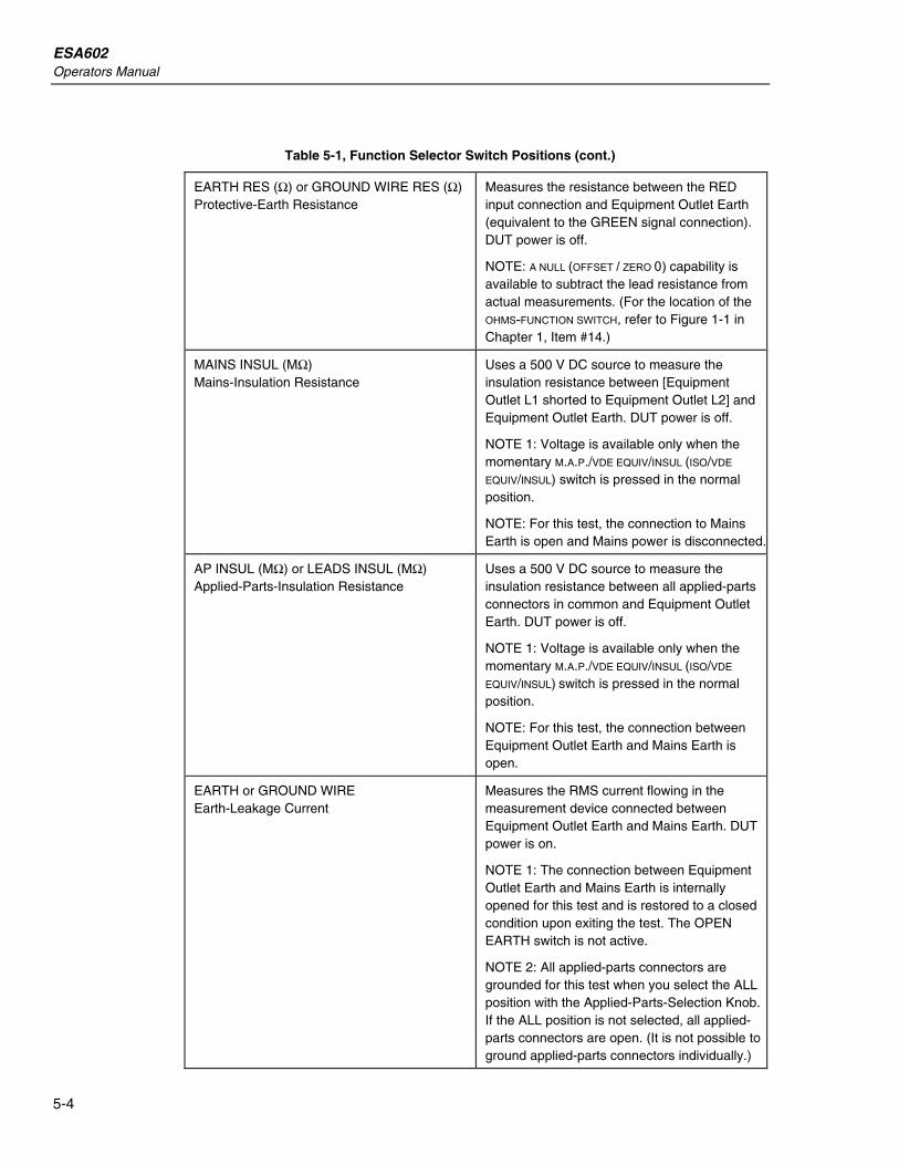
EARTH RES (Ω) or GROUND WIRE RES (Ω) Protective-Earth Resistance
Measures the resistance between the RED input connection and Equipment Outlet Earth (equivalent to the GREEN signal connection). DUT power is off.
NOTE: A NULL (OFFSET / ZERO 0) capability is available to subtract the lead resistance from actual measurements. (For the location of the OHMS-FUNCTION SWITCH, refer to Figure 1-1 in Chapter 1, Item #14.)
MAINS INSUL (MΩ) Mains-Insulation Resistance
Uses a 500 V DC source to measure the insulation resistance between [Equipment Outlet L1 shorted to Equipment Outlet L2] and Equipment Outlet Earth. DUT power is off.
NOTE 1: Voltage is available only when the momentary M.A.P./VDE EQUIV/INSUL (ISO/VDE
EQUIV/INSUL) switch is pressed in the normal position.
NOTE: For this test, the connection to Mains Earth is open and Mains power is disconnected.
AP INSUL (MΩ) or LEADS INSUL (MΩ) Applied-Parts-Insulation Resistance
Uses a 500 V DC source to measure the insulation resistance between all applied-parts connectors in common and Equipment Outlet Earth. DUT power is off.
NOTE 1: Voltage is available only when the momentary M.A.P./VDE EQUIV/INSUL (ISO/VDE
EQUIV/INSUL) switch is pressed in the normal position.
NOTE: For this test, the connection between Equipment Outlet Earth and Mains Earth is open.
EARTH or GROUND WIRE Earth-Leakage Current
Measures the RMS current flowing in the measurement device connected between Equipment Outlet Earth and Mains Earth. DUT power is on.
NOTE 1: The connection between Equipment Outlet Earth and Mains Earth is internally opened for this test and is restored to a closed condition upon exiting the test. The OPEN EARTH switch is not active.
NOTE 2: All applied-parts connectors are grounded for this test when you select the ALL position with the Applied-Parts-Selection Knob. If the ALL position is not selected, all applied-parts connectors are open. (It is not possible to ground applied-parts connectors individually.)

Local Control Function Selection 5
5-5
Table 5-1, Function Selector Switch Positions (cont.)
ENCLOSURE or CHASSIS Enclosure-Leakage Current
Measures the RMS current flowing in the tester’s measurement device connected between the RED signal connection and Mains Earth. DUT power is on.
NOTE 1: All applied-parts connectors are grounded for this test when you select the ALL position with the Applied-Parts-Selection Knob. If the ALL position is not selected, all applied-parts connectors are open. (It is not possible to ground applied-parts connectors individually.)
NOTE 2: To measure the leakage between two separate parts of the enclosure, connect two test leads to two ECG connectors, and perform the Patient-Auxiliary-Leakage-Current test.
PATIENT or LEAD TO GROUND Patient-Leakage Current
Measures the RMS current flowing in the tester’s measurement device connected between each individual applied-parts connector, or all applied-parts connectors in common, and Mains Earth. DUT power is on.
PATIENT AUX or LEAD TO LEADS Patient-Auxiliary-Leakage Current
Places the tester’s measurement-device circuit in series between each individual applied-parts connector and all other applied-parts connectors in common. DUT power is on.
MAINS APPLIED PARTS or LEAD ISOLATIONMains-on-Applied-Parts-Leakage Current
Places the tester’s measurement-device circuit in series with the current-limited M.A.P. voltage and each individual applied-parts connector, or all applied-parts connectors in common, and Mains Earth. DUT power is ON.
NOTE 1: Voltage is available only when the momentary M.A.P./VDE EQUIV/INSUL
(ISO/VDE/EQUIV INSUL) switch is pressed. Both NORMAL M.A.P. voltage (in phase with Mains voltage) and REVERSE M.A.P. voltage (180 degrees out-of-phase with Mains voltage) are available.
NOTE 2: The internal leakage generated by the coupling between the M.A.P. voltage, the tester circuitry and enclosure can be eliminated by subtracting an offset equivalent to this internal leakage from the measured reading. (The null current value is determined when the unit is calibrated periodically.)

ESA602 Operators Manual
5-6
Table 5-1, Function Selector Switch Positions (cont.)
VDE: EQUIV DEVICE VDE: Equivalent-Device-Leakage Current
Places the tester’s measurement-device circuit in series with a current-limited M.A.P. voltage that is connected between [Equipment Outlet L1 shorted to Equipment Outlet L2 and disconnected from Mains power] and [Equipment Outlet Earth, Mains Earth, the RED signal connection, and all applied-parts connectors in common]. DUT power is off.
NOTE 1: Voltage is available only when the momentary M.A.P./VDE EQUIV/INSUL (ISO/ VDE/EQUIV INSUL) switch is pressed. Both normal m.a.p. voltage (in phase with Mains voltage) and reverse m.a.p. voltage (180 degrees out-of-phase with Mains voltage) are available.
VDE: EQUIV PATIENT VDE: Equivalent-Patient-Leakage Current
Places the tester’s measurement-device circuit in series with a current-limited M.A.P. voltage that is connected between [Equipment Outlet L1, Equipment Outlet L2, Outlet Earth, Mains Earth, and the RED signal connection] and [all applied-parts connectors in common]. DUT power is off.
NOTE 1: Voltage is available only when the momentary M.A.P./VDE EQUIV/INSUL (ISO / VDE/EQUIV INSUL) switch is pressed. Both normal M.A.P. voltage (in phase with Mains voltage) and reverse M.A.P. voltage (180 degrees out-of-phase with Mains voltage) are available.
VDE: DIFF CURRENT VDE: Differential-Leakage Current
Measures the magnitude of the differential current flowing in the Equipment Outlet L1 and L2 circuits.
The reading is taken after selecting this function. DUT power is on.
DUAL LEAD LEAKAGE Dual-Lead-Leakage Current
Places the tester’s measurement-device circuit in series with the RED signal connection and the BLACK signal connection. DUT power is on.
DUAL LEAD VOLTAGE (V) Dual-Lead Voltage
Measures the RMS voltage between the RED signal connection and the BLACK signal connection. DUT power is on.

Local Control Function Selection 5
5-7
Table 5-2. Active Switch Settings for Selected Tests
ACTIVE SWITCH SETTINGS for the TEST SELECTED
SELECTED TEST
FUNCTION SELECTOR
KNOB
APPLIED-PARTS
SELECTOR KNOB
M.A.P./VDEEQUIV/ INSUL
SWITCH (momentary)
NEUTRAL SWITCH
EARTH SWITCH
POLARITY SWITCH
OHMS FUNCTION
SWITCH (momentary)
Measures the RMS voltage between Mains L1 and Mains L2.
Mains Voltage
MAINS VOLT (V)
INACTIVE INACTIVE INACTIVE INACTIVE INACTIVE INACTIVE
Measures the two-lead resistance between the RED input connection and Equipment Outlet Earth (equivalent to the GREEN signal connection).
Earth Resistance
EARTH RES (Ω)
INACTIVE INACTIVE INACTIVE INACTIVE INACTIVE ACTIVE
Uses a 500 V DC source to measure the insulation resistance between [Equipment Outlet L1 shorted to Equipment Outlet L2 and disconnected from Mains power] and Equipment Outlet Earth.
Mains-Insulation Resistance
MAINS INSUL (MΩ)
INACTIVE ACTIVE INACTIVE INACTIVE INACTIVE INACTIVE
Uses a 500 V DC source to measure the insulation resistance between all applied-part connectors in common and Equipment Outlet Earth.
Applied-Parts-
Insulation Resistance AP INSUL
(MΩ) INACTIVE ACTIVE INACTIVE INACTIVE INACTIVE INACTIVE
Measures the RMS current flowing in the measurement device connected between Equipment Outlet Earth and Mains Earth.
Earth Leakage
EARTH INACTIVE INACTIVE ACTIVE INACTIVE ACTIVE INACTIVE
Measures the RMS current flowing in the tester’s measurement device connected between the RED signal connection and Mains Earth.
Enclosure Leakage
ENCLO- SURE
INACTIVE INACTIVE ACTIVE ACTIVE ACTIVE INACTIVE
Measures the RMS current flowing in the tester’s measurement device connected between each individual applied-part connector, or all applied-part connectors in common, and Mains Earth
Patient-Lead
Leakage PATIENT ACTIVE INACTIVE ACTIVE ACTIVE ACTIVE INACTIVE
Places the tester’s measurement-device circuit in series between each individual applied-part connector and all other applied-part connectors in common.
Patient-Auxiliary- Current Leakage PATIENT
AUX ACTIVE INACTIVE ACTIVE ACTIVE ACTIVE INACTIVE
Places the tester’s measurement-device circuit in series with the current-limited M.A.P. voltage and each individual applied-part connector, or all applied-part connectors in common, and Mains Earth.
M.A.P. Leakage
MAINS APPLIED PARTS
ACTIVE ACTIVE INACTIVE INACTIVE ACTIVE INACTIVE

ESA602 Operators Manual
5-8
Table 5-2, Active Switch Settings for Selected Tests (cont.)
ACTIVE SWITCH SETTINGS for the TEST SELECTED
SELECTED TEST
FUNCTION SELECTOR
KNOB
APPLIED-PARTS
SELECTOR KNOB
M.A.P./VDEEQUIV/ INSUL
SWITCH (momentary)
NEUTRAL SWITCH
EARTH SWITCH
POLARITY SWITCH
OHMS FUNCTION
SWITCH (momentary)
Places the tester’s measurement-device circuit in series with a current-limited M.A.P. voltage that is connected between [Equipment Outlet L1 shorted to Equipment Outlet L2 and disconnected from Mains power] and [Equipment Outlet Earth, Mains Earth, the RED signal connection, and all applied-part connectors in common].
Equivalent-Device
Leakage
VDE: EQUIV
DEVICE
INACTIVE ACTIVE INACTIVE INACTIVE INACTIVE INACTIVE
Places the tester’s measurement-device circuit in series with a current-limited M.A.P. voltage that is connected between [Equipment Outlet L1, Equipment Outlet L2, Outlet Earth, Mains Earth, and the RED signal connection] and [all applied-part connectors in common].
Equivalent-Patient
Leakage
VDE: EQUIV
PATIENT
INACTIVE ACTIVE INACTIVE INACTIVE INACTIVE INACTIVE
Measures the magnitudes of the differential current flowing in the Equipment Outlets L1 and L 2 circuits.
Differential-Current Leakage VDE: DIFF
CURRENT INACTIVE INACTIVE INACTIVE INACTIVE ACTIVE INACTIVE
Places the tester’s measurement-device circuit in series with the RED signal connection and the BLACK signal connection.
Dual-Lead Leakage
DUAL LEAD
LEAKAGE
INACTIVE INACTIVE ACTIVE INACTIVE ACTIVE INACTIVE
Measures the RMS voltage between the RED signal connection and the BLACK signal connection.
Dual-Lead Voltage
DUAL-LEAD
VOLTAGE (V)
INACTIVE INACTIVE ACTIVE ACTIVE ACTIVE INACTIVE
Local Control Performing Electrical-Safety Tests 5
5-9
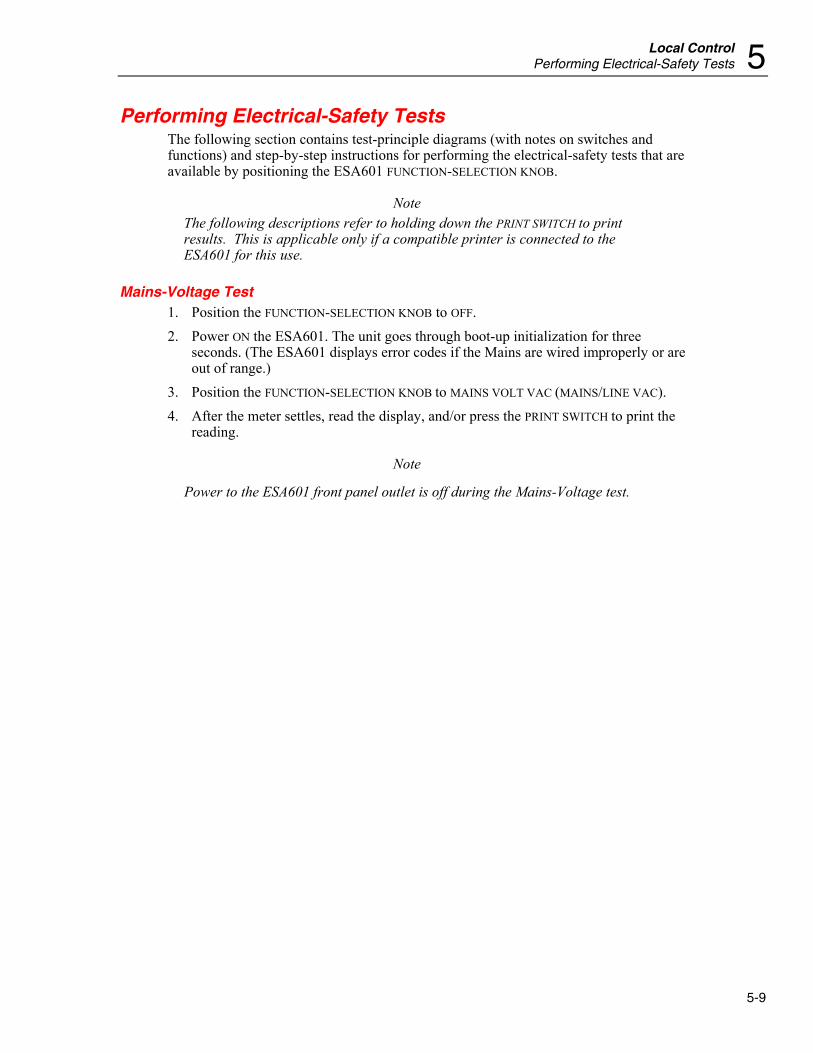
Performing Electrical-Safety Tests The following section contains test-principle diagrams (with notes on switches and functions) and step-by-step instructions for performing the electrical-safety tests that are available by positioning the ESA601 FUNCTION-SELECTION KNOB.
Note The following descriptions refer to holding down the PRINT SWITCH to print results. This is applicable only if a compatible printer is connected to the ESA601 for this use.
Mains-Voltage Test 1. Position the FUNCTION-SELECTION KNOB to OFF. 2. Power ON the ESA601. The unit goes through boot-up initialization for three
seconds. (The ESA601 displays error codes if the Mains are wired improperly or are out of range.)
3. Position the FUNCTION-SELECTION KNOB to MAINS VOLT VAC (MAINS/LINE VAC). 4. After the meter settles, read the display, and/or press the PRINT SWITCH to print the
reading.
Note
Power to the ESA601 front panel outlet is off during the Mains-Voltage test.

ESA602 Operators Manual
5-10
Protective-Earth-Resistance Test The Protective-Earth-Resistance test measures the impedance between the outlet PE terminal of the ESA601and exposed conductive parts of the DUT that are connected to the DUT’s Protective Earth. Figure 5-1 shows the electrical connections between the ESA601 and the DUT. The table below the diagram indicates the position of switches in the diagram during the test. Test current is applied for as long as the switch is held, which should be until a stable reading is taken (approximately three seconds). DUT power is off.
RED TERMINAL
TEST LEAD
GREENTERMINAL
OHMCURRENTSOURCE1A DC
CONDUCTIVE PART
DUT_PE FE
S3PE
L2S1 S2
DUT_L2
DUT_L1DEVICE UNDER TEST
APPLIEDPART
MAINS
L1
S5
+
_
EARTHOPEN
L2OPEN
ayr05f.eps
Figure 5-1. Protective-Earth-Resistance Test Configuration
SWITCH DIAGRAM
REFERENCE ESA601 NAME
ACTION
S1 NEUTRAL N/A S2 POLARITY N/A S3 EARTH OPEN S5 (N/A)

Local Control Performing Electrical-Safety Tests 5
5-11
When the EARTH RES Ω (GROUND WIRE RES Ω) function is selected initially, and the OHMS-FUNCTION SWITCH is set to the default (OFF) position, the ESA601 display indicates PE (Protective Earth), and the null offset value is equal to the last null offset value.
Action 1. Position the FUNCTION-SELECTION KNOB to EARTH RES Ω (GROUND WIRE RES Ω). 2. Connect the DUT power cord to the test receptacle on the ESA601 3. Connect the banana plug end of the red test lead into the RED signal jack and the
probe end into to the GREEN signal jack that is labeled PE TEST POINT.* 4. Depress and hold down the OHMS-FUNCTION SWITCH in the OFFSET/ZERO 0 position. 5. After the meter settles, release the switch. If the operation is successful, a null offset
is saved, and the ESA601 display indicates a string of zeroes. (If the meter will not zero, the ESA601 display indicates OL when the switch is released, meaning that the lead resistance is too high.)
6. Disconnect the lead’s probe end from the PE-TEST POINT, and connect to the DUT enclosure at desired points. Connect the DUT power cord to the test receptacle on the ESA601.
7. Depress and hold down the OHMS-FUNCTION SWITCH in the MEASURE Ω position until a stable reading is obtained (approximately three seconds).
8. Release the switch to hold and display the reading. 9. Press the PRINT SWITCH to print the reading. 10. Repeat steps 6 through 9 as many times as necessary, using the RED test lead to
connect to all exposed conductive parts of the DUT.
Note When the EARTH RES Ω (GROUND WIRE RES Ω) function is exited, the NULL value (OFFSET/ZERO) is held. To ensure accuracy of readings, it is recommended that the nulling of the test lead resistance be performed periodically, whenever a test lead is disconnected and reconnected, when results are questionable, or when a new test lead is applied.

ESA602 Operators Manual
5-12
Mains-Insulation-Resistance Test The Mains-Insulation-Resistance test measures the insulation resistance (at 500 V DC) between L1 and L2 and the DUT’S Protective Earth. Figure 5-2 shows the electrical connections between the ESA601 and the DUT. The table below the diagram indicates the position of switches in the diagram during the test. Voltage is available only when momentary M.A.P./VDE/INSUL (ISO/VDE EQUIV/INSUL) switch is pressed in the normal position. DUT power is off.
CONDUCTIVE PART
DUT_PE
S3
PE
DUT_L2
DUT_L1
EARTHOPEN
MD
+
_500VDC
MEGOHMS
FE
DEVICE UNDER TEST
APPLIEDPART
ayr06f.eps
Figure 5-2. Mains-Insulation-Resistance Test Configuration
SWITCH DIAGRAM
REFERENCE ESA601 NAME
ACTION
S3 EARTH OPEN
Action 1. Position the FUNCTION-SELECTION KNOB to MAINS INSUL MΩ. 2. Connect the DUT power cord to the test receptacle on the ESA601. 3. Depress and hold down the M.A.P./VDE EQUIV/INSUL SWITCH (ISO/VDE EQUIV/INSUL)
in the NORMAL position. 4. After the meter settles, release the switch to hold and display a reading. 5. Press the PRINT SWITCH to print the reading.

Local Control Performing Electrical-Safety Tests 5
5-13
Applied-Parts-Insulation-Resistance Test The Applied-Parts-Insulation-Resistance test measures the insulation resistance (at 500 V DC) between all applied-parts connections and the DUT’S Protective Earth. Figure 5-3 shows the electrical connections between the ESA601 and the DUT. The table below the diagram indicates the position of switches in the diagram during the test. Voltage is available only when momentary M.A.P./VDE/INSUL (ISO/VDE EQUIV/INSUL) switch is pressed in the normal position. DUT power is off.
CONDUCTIVE PART
DUT_PE
S3
PE
DUT_L2
DUT_L1
EARTHOPEN
MD
+
_500VDC
MEGOHMS
FE
DEVICE UNDER TEST
APPLIEDPART
ayr07f.eps
Figure 5-3. Applied-Parts-Insulation-Resistance Test Configuration
SWITCH DIAGRAM
REFERENCE ESA601 NAME
ACTION
S3 EARTH OPEN
Note The Applied-Parts-Insulation-Resistance test is applicable only to DUTs with applied parts.
Action 1. Position the FUNCTION-SELECTION KNOB to AP INSUL MΩ (LEAD INSUL MΩ). 2. Connect the DUT applied parts to the applied-parts jacks on the ESA601. Connect
the DUT power cord to the test receptacle on the ESA601. 3. Select ALL on the APPLIED PARTS selector knob. 4. Depress and hold down the M.A.P./VDE EQUIV/INSUL SWITCH (ISO/VDE EQUIV/INSUL)
in the NORMAL position. 5. After the meter settles, release the switch to hold and display a reading. 6. Press the PRINT SWITCH to print the reading.

ESA602 Operators Manual
5-14
Earth-Leakage-Current Test The Earth-Leakage-Current Test measures the current flowing in the DUT’s Protective Earth. Figure 5-4 shows the electrical connections between the ESA601 and the DUT. The table below the diagram indicates the position of switches in the diagram during the test. DUT power is on. The test is performed with NORMAL and REVERSE Mains supply polarity using the POLARITY SWITCH, and single-fault condition OPEN L2 using the NEUTRAL SWITCH. For type-BF and type-CF equipment, measure with APPLIED-PARTS-SELECTION KNOB both OPEN (by selecting anything other than ALL) and CLOSED (by selecting ALL).
CONDUCTIVE PART
DUT_PE
APPLIED PART
S3
PE
L2S1 S2
DUT_L2
DUT_L1
MAINS
L1
S5
EARTHOPEN
L2OPEN
S4
MD
A
FE
DEVICE UNDER TEST
APPLIEDPART
ayr08f.eps
Figure 5-4. Earth-Leakage-Current Test Configuration
SWITCH DIAGRAM
REFERENCE ESA601 NAME
ACTION
S1 NEUTRAL VARIABLE S2 POLARITY VARIABLE S3 EARTH OPEN S4 APPLIED-PARTS-SELECTION KNOB VARIABLE* S5 (N/A)

Local Control Performing Electrical-Safety Tests 5
5-15
Action 1. Position the FUNCTION-SELECTION KNOB to EARTH (GROUND WIRE). 2. Position the APPLIED-PARTS-SELECTION KNOB to RA or AP1 (if applicable).
Note For type-BF and type-CF equipment, perform the measurement with the APPLIED PARTS selection knob both open (by selecting any selection except ALL, in the above case RA or AP1) and closed (by selecting ALL).
3. Set the NEUTRAL SWITCH to CLOSED. 4. Set the POLARITY SWITCH to NORMAL. 5. Connect the DUT power cord to the test receptacle on the ESA601. 6. After the meter settles, read the display, and/or press the PRINT SWITCH to print the
reading. 7. Set the NEUTRAL SWITCH to OPEN. 8. After the meter settles, read the display, and/or press the PRINT SWITCH to print the
reading. 9. Return the NEUTRAL SWITCH to CLOSED. 10. Set the POLARITY SWITCH to REVERSE and wait for the REVERSE POLARITY indicator
to illuminate. 11. After the meter settles, read the display, and/or press the PRINT SWITCH to print the
reading. 12. Repeat steps 7 and 8.

ESA602 Operators Manual
5-16
Enclosure-Leakage-Current Test The Enclosure-Leakage-Current test measures the current flowing from the RED terminal to MAINS PE. Figure 5-5 shows the electrical connections between the ESA601 and the DUT. The table below the diagram indicates the position of switches in the diagram during the test. DUT power is on. The test is performed with NORMAL and REVERSE Mains supply polarity using the POLARITY SWITCH, and single-fault conditions using the NEUTRAL SWITCH, and the EARTH SWITCH. For type-BF and type-CF equipment, measure with applied APPLIED-PARTS-SELECTION KNOB both OPEN (by selecting anything other than ALL) and CLOSED (by selecting ALL).
CONDUCTIVE PART
DUT_PE
APPLIED PART
TEST LEAD
S3
PE
L2S1 S2
DUT_L2
DUT_L1
MAINS
L1
S5
EARTHOPEN
L2OPEN
S4
MDA
FE
DEVICE UNDER TEST
APPLIEDPART
ayr09f.eps
Figure 5-5. Enclosure-Leakage-Current Test Configuration
SWITCH DIAGRAM
REFERENCE ESA601 NAME
ACTION
S3 EARTH OPEN

Local Control Performing Electrical-Safety Tests 5
5-17
Action 1. Position the FUNCTION-SELECTION KNOB to ENCLOSURE (CHASSIS). 2. Set the APPLIED-PARTS-SELECTION KNOB to RA or AP1 (if applicable).
Note For type-BF and type-CF equipment, perform the measurement with the APPLIED PARTS selection knob both open (by selecting any selection except ALL, in the above case RA or AP1) and closed (by selecting ALL).
3. Set the POLARITY SWITCH to NORMAL. 4. Set the NEUTRAL SWITCH to CLOSED. 5. Set the EARTH SWITCH to CLOSED. 6. Connect the banana plug end of the RED test lead into the RED signal jack and the
probe end of the RED test lead to the DUT enclosure. Connect the DUT power cord to the test receptacle on the ESA601.
7. After the meter settles, read the display, and/or press the PRINT SWITCH to print the reading.
8. Set the EARTH SWITCH to OPEN. 9. Read the display, and/or press the PRINT SWITCH to print the reading. 10. Return the EARTH SWITCH to CLOSED. 11. Set the NEUTRAL SWITCH to OPEN. 12. Read the display, and/or press the PRINT SWITCH to print the reading. 13. Set the POLARITY SWITCH to REVERSE, and wait for the REVERSE POLARITY indicator
to illuminate. 14. Read the display, and/or press the PRINT SWITCH to print the reading. 15. Repeat steps 8 through 12 while the POLARITY SWITCH is in the REVERSE position.

ESA602 Operators Manual
5-18
Patient-Leakage-Current Test The Patient-Leakage-Current test measures the current flowing between a selected applied part, or ALL applied parts, and the Mains PE. Figure 5-6 shows the electrical connections between the ESA601 and the DUT. The table below the diagram indicates the position of switches in the diagram during the test. DUT power is on. The test is performed with NORMAL and REVERSE Mains supply polarity using the POLARITY SWITCH and single-fault conditions using the EARTH SWITCH and the NEUTRAL SWITCH.
CONDUCTIVE PART
DUT_PE
S3
PEA
L2
S1 S2
DUT_L2
DUT_L1
MAINS
L1
S5
EARTHOPEN
L2OPEN
MD
LEAD SELECT
S4
FE
DEVICE UNDER TEST
APPLIEDPART
ayr10f.eps
Figure 5-6. Patient-Leakage-Current Test Configuration
SWITCH DIAGRAM
REFERENCE ESA601 NAME
ACTION
S1 NEUTRAL VARIABLE S2 POLARITY VARIABLE S3 EARTH VARIABLE S4 APPLIED-PARTS-SELECTION KNOB VARIABLE S5 (N/A)

Local Control Performing Electrical-Safety Tests 5
5-19
Note The Patient-Leakage-Current test is applicable only to DUTs with applied parts.
Action 1. Position the FUNCTION-SELECTION KNOB to PATIENT (LEAD TO GROUND). 2. Position the APPLIED-PARTS-SELECTION KNOB to ALL. 3. Set the NEUTRAL SWITCH to CLOSED. 4. Set the EARTH SWITCH to CLOSED. 5. Set the POLARITY SWITCH to NORMAL, and wait for the analyzer to switch to normal. 6. Connect the banana plug end of the RED test lead into the RED signal jack, and the
probe end of the RED test lead to the DUT enclosure; connect the DUT applied parts to the applied-parts jacks on the ESA601; connect the DUT power cord to the test receptacle on the ESA601.
7. After the meter settles, read the display, and/or press the PRINT SWITCH to print the reading.
8. Set the NEUTRAL SWITCH to OPEN. 9. After the meter settles, read the display, and/or press the PRINT SWITCH to print the
reading. 10. Set the NEUTRAL SWITCH to CLOSED. 11. Set the EARTH SWITCH to OPEN. 12. After the meter settles, read the display, and/or press the PRINT SWITCH to print the
reading. 13. Set the EARTH SWITCH to CLOSED. 14. Set the POLARITY SWITCH to REVERSE, and wait for the REVERSE POLARITY indicator
to illuminate. 15. Repeat steps 8 through 13. 16. Cycle the APPLIED-PARTS-SELECTION KNOB from RA (AP1) through V6 (AP10) (or the
number of leads that are connected), repeating steps 8 through 15 for each applied-parts selection.
ESA602 Operators Manual
5-20
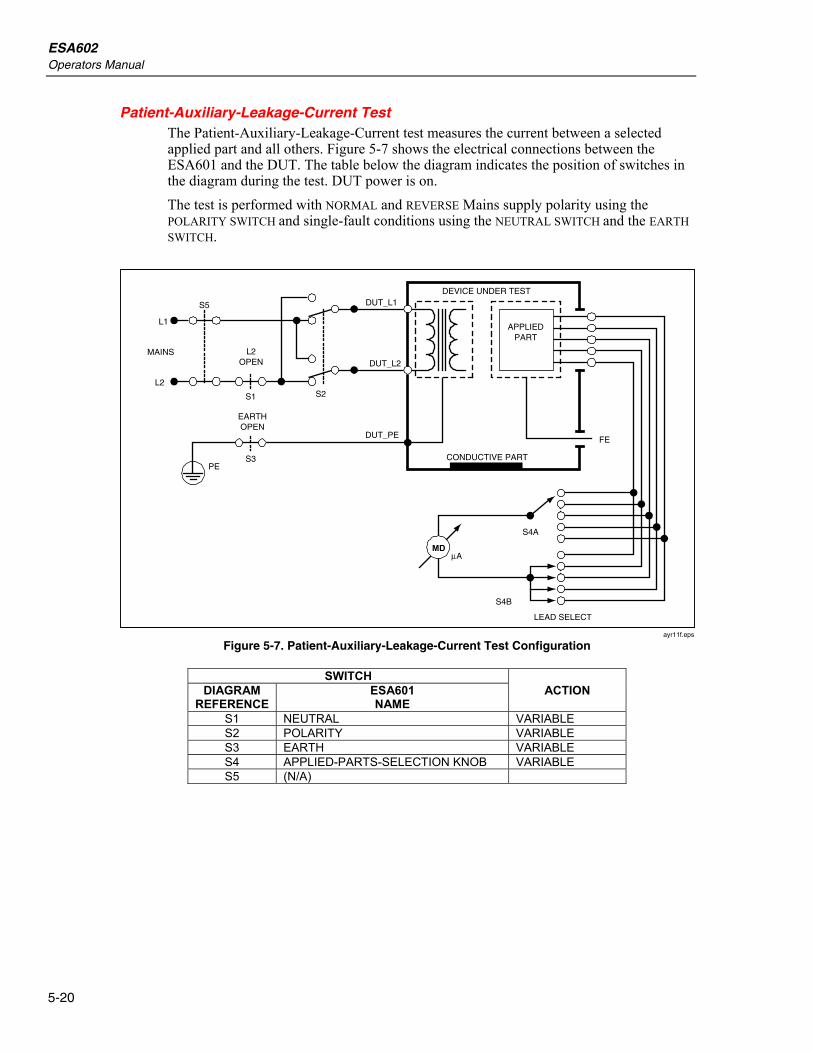
Patient-Auxiliary-Leakage-Current Test The Patient-Auxiliary-Leakage-Current test measures the current between a selected applied part and all others. Figure 5-7 shows the electrical connections between the ESA601 and the DUT. The table below the diagram indicates the position of switches in the diagram during the test. DUT power is on. The test is performed with NORMAL and REVERSE Mains supply polarity using the POLARITY SWITCH and single-fault conditions using the NEUTRAL SWITCH and the EARTH SWITCH.
CONDUCTIVE PART
DUT_PE
S3PE
L2
S1 S2
DUT_L2
DUT_L1
MAINS
L1
S5
EARTHOPEN
L2OPEN
LEAD SELECT
MD
S4A
A
S4B
FE
DEVICE UNDER TEST
APPLIEDPART
ayr11f.eps
Figure 5-7. Patient-Auxiliary-Leakage-Current Test Configuration
SWITCH DIAGRAM
REFERENCE ESA601 NAME
ACTION
S1 NEUTRAL VARIABLE S2 POLARITY VARIABLE S3 EARTH VARIABLE S4 APPLIED-PARTS-SELECTION KNOB VARIABLE S5 (N/A)

Local Control Performing Electrical-Safety Tests 5
5-21
Note The Patient-Auxiliary-Leakage-Current test is applicable only to DUTs with applied parts.
Action 1. Position the FUNCTION-SELECTION KNOB to PATIENT AUX (LEAD TO LEADS). 2. Position the APPLIED-PARTS-SELECTION KNOB to RA. 3. Set the NEUTRAL SWITCH to CLOSED. 4. Set the EARTH SWITCH to CLOSED. 5. Set the POLARITY SWITCH to NORMAL, and wait for the analyzer to switch to normal. 6. Connect the banana plug end of the RED test lead into the RED signal jack, and the
probe end of the RED test lead to the DUT enclosure; connect the DUT applied parts to the applied-parts jacks on the ESA601; connect the DUT power cord to the test receptacle on the ESA601.
7. After the meter settles, read the display, and/or press the PRINT SWITCH to print the reading.
8. Set the NEUTRAL SWITCH to OPEN. 9. After the meter settles, read the display, and/or press the PRINT SWITCH to print the
reading. 10. Set the NEUTRAL SWITCH to CLOSED. 11. Set the EARTH SWITCH to OPEN. 12. After the meter settles, read the display, and/or press the PRINT SWITCH to print the
reading. 13. Set the EARTH SWITCH to CLOSED. 14. Set the POLARITY SWITCH to REVERSE, and wait for the REVERSE POLARITY indicator
to illuminate. 15. Repeat steps 8 through 13. 16. Cycle the APPLIED-PARTS-SELECTION KNOB from RL (AP2) through V6 (AP10) (or the
number of leads that are connected), repeating steps 7 through 15 for each applied-parts selection.

ESA602 Operators Manual
5-22
Mains-On-Applied-Parts-Leakage-Current Test The Mains-On-Applied-Parts-Leakage-Current test measures the current that flows in response to an isolated AC voltage applied between a selected applied part, or ALL applied parts, and Earth (and any conductive part connected to the RED terminal). Figure 5-7 shows the electrical connections between the ESA601 and the DUT. The table below the diagram indicates the position of switches in the diagram during the test. DUT power is on. The test is performed with NORMAL and REVERSE Mains supply polarity using the POLARITY SWITCH, and NORMAL and REVERSE isolated voltage supply polarity using the M.A.P./VDE EQUIV/INSUL (ISO/VDE EQUIV/INSUL) SWITCH. The magnitude of the voltage is at least 110 % of the Mains voltage.
CONDUCTIVE PART
DUT_PE
S3
PE
L2S1 S2
DUT_L2
DUT_L1
MAINS
L1
L2
L1
S5
EARTH OPEN
L2OPEN
S4
LEAD SELECT
S6
A
RED TERMINALTEST LEAD
MD1:1.1
ISOLATIONTRANSFORMER
FE
DEVICE UNDER TEST
APPLIEDPART
ayr12f.eps
Figure 5-8. Mains-On-Applied-Parts-Leakage-Current Test Configuration
SWITCH DIAGRAM
REFERENCE ESA601 NAME
ACTION
S1 NEUTRAL CLOSED S2 POLARITY VARIABLE S3 EARTH CLOSED S4 M.A.P./500 V VARIABLE S5 (N/A) S6 APPLIED-PARTS-SELECTION KNOB VARIABLE

Local Control Performing Electrical-Safety Tests 5
5-23
Note The Mains-on-Applied-Parts-Leakage-Current test is applicable only to DUTs with applied parts.
Action 1. Position the FUNCTION-SELECTION KNOB to MAINS APPLIED PARTS (LEAD
ISOLATION). 2. Position the APPLIED-PARTS-SELECTION KNOB to ALL. 3. Set the POLARITY SWITCH to NORMAL, and wait for the analyzer to switch to normal. 4. Connect the banana plug end of the RED test lead into the RED signal jack, and the
probe end of the RED test lead to the DUT enclosure; connect the DUT applied parts to the applied-parts jacks on the ESA601; connect the DUT power cord to the test receptacle on the ESA601.
5. Depress and hold down the M.A.P./VDE EQUIV/INSUL (ISO/VDE EQUIV/INSUL) SWITCH in the NORMAL position.
6. After the meter settles, release the switch to hold and display the reading and/or press the PRINT SWITCH to print the reading.
7. Depress and hold down the M.A.P./VDE EQUIV/INSUL (ISO/VDE EQUIV/INSUL) SWITCH in the REVERSE position.
8. After the meter settles, read the display, and/or press the PRINT SWITCH to print the reading.
9. Set the POLARITY SWITCH to REVERSE, and wait for the REVERSE POLARITY indicator to illuminate.
10. Repeat steps 5 through 8. 11. Set the POLARITY SWITCH to NORMAL, and wait for the analyzer to switch to normal. 12. Cycle the APPLIED-PARTS-SELECTION KNOB from RA (AP1) through V6 (AP10) (or the
number of leads that are connected), repeating steps 5 through 11 for each applied-parts selection.
13. Disconnect all applied parts from the analyzer. 14. Using the probe end of the RED test lead, touch any exposed conductive part of the
DUT and wait for the meter to settle. 15. While keeping the probe end of the RED test lead connected to the DUT, read the
display, and/or press the PRINT SWITCH to print the reading. 16. Repeat steps 14 through 15 for each exposed conductive part tested.

ESA602 Operators Manual
5-24
VDE: Equivalent-Device-Leakage-Current Test The VDE:Equivalent-Device-Leakage-Current test measures the current that flows between the shorted Mains terminals (L1 and L2) of the DUT to the PE, applied parts, and exposed conductive parts of the DUT (connected to the RED signal connection) in response to an isolated AC voltage source with a magnitude of at least 110 % of Mains voltage. Figure 5-8 shows the electrical connections between the ESA601 and the DUT. The table below the diagram indicates the position of switches in the diagram during the test. DUT power is off. This test is performed with both NORMAL and REVERSE isolated voltage supply polarity using the M.A.P./VDE EQUIV/INSUL (ISO /VDE EQUIV/INSUL) SWITCH.
CONDUCTIVE PART
DUT_PE
S3PE
DUT_L2
DUT_L1
L2
L1
EARTHOPEN
RED TERMINALTEST LEAD
MDA
1:1.1
ISOLATIONTRANSFORMER
FE
DEVICE UNDER TEST
APPLIEDPART
ayr13f.eps
Figure 5-9. VDE: Equivalent-Device-Leakage-Current Test Configuration
SWITCH DIAGRAM
REFERENCE ESA601 NAME
ACTION
S3 EARTH CLOSED

Local Control Performing Electrical-Safety Tests 5
5-25
Action 1. Connect the banana plug end of the RED test lead into the RED signal jack, and the
probe end of the RED test lead to the DUT enclosure; connect the DUT applied parts to the applied-parts jacks on the ESA601; connect the DUT power cord to the test receptacle on the ESA601.
2. Position the APPLIED PARTS (or ECG LEADS) selector knob to ALL. 3. Position the FUNCTION-SELECTION KNOB to VDE: EQUIV DEVICE. 4. Depress and hold down the M.A.P./VDE EQUIV/INSUL (ISO/VDE EQUIV/INSUL) SWITCH
in the NORMAL position. 5. After the meter settles, release the switch to hold and display the reading and/or press
the PRINT SWITCH to print the reading. 6. Depress and hold down the M.A.P./VDE EQUIV SWITCH in the REVERSE position. 7. After the meter settles, release the switch to hold and display the reading and/or press
the PRINT SWITCH to print the reading.

ESA602 Operators Manual
5-26
VDE: Equivalent-Patient-Leakage-Current Test The VDE:Equivalent-Patient-Leakage-Current test measures the current that flows between the applied-parts terminals of the DUT to the PE, Mains terminals (L1 and L2), and exposed conductive parts of the DUT (connected to RED signal connection) in response to an isolated AC voltage source with a magnitude of at least 110 % of Mains voltage. Figure 5-10 shows the electrical connections between the ESA601 and the DUT. DUT power is off. The table below the diagram indicates the position of switches in the diagram during the test. This test is performed with both NORMAL and REVERSE isolated voltage supply polarity using the M.A.P./VDE EQUIV/INSUL (ISO/VDE EQUIV/INSUL) SWITCH.
CONDUCTIVE PART
DUT_PE
S3PE
DUT_L2
DUT_L1
L2
L1
EARTHOPEN
RED TERMINAL TEST LEAD
AMD
1:1.1
ISOLATIONTRANSFORMER
+
MAINS
FE
DEVICE UNDER TEST
APPLIEDPART
ayr14f.eps
Figure 5-10. VDE: Equivlent-Patient-Leakage-Current Test Configuration
SWITCH DIAGRAM
REFERENCE ESA601 NAME
ACTION
S3 EARTH CLOSED

Local Control Performing Electrical-Safety Tests 5
5-27
Action 1. Connect the banana plug end of the RED test lead into the RED signal jack, and the
probe end of the RED test lead to the DUT enclosure; connect the DUT applied parts to the applied-parts jacks on the ESA601; connect the DUT power cord to the test receptacle on the ESA601.
2. Position the APPLIED PARTS (or ECG LEADS) selector knob to ALL. 3. Position the FUNCTION-SELECTION KNOB to VDE: EQUIV PATIENT. 4. Depress and hold down the M.A.P./VDE EQUIV/INSUL (ISO/VDE EQUIV/INSUL) SWITCH
in the NORMAL position. 5. After the meter settles, release the switch to hold and display the reading and/or press
the PRINT SWITCH to print the reading. 6. Depress and hold down the M.A.P./VDE EQUIV SWITCH in the REVERSE position. 7. After the meter settles, release the switch to hold and display the reading and/or press
the PRINT SWITCH to print the reading. 8. Disconnect all applied parts from the analyzer.

ESA602 Operators Manual
5-28
VDE: Differential-Leakage-Current Test The VDE: Differential-Leakage-Current test measures the magnitudes of the differential current flowing in the Equipment Outlet L1 and L2 circuits. Figure 5-11 shows the electrical connections between the ESA601 and the DUT. The reading is taken after selecting this function. DUT power is ON.
CONDUCTIVE PART
DUT_PE
S3PE
L2S1 S2
DUT_L2
DUT_L1
MAINS
L1
S5
EARTHOPEN
L2OPEN
FE
DEVICE UNDER TEST
APPLIEDPART
ayr15f.eps
Figure 5-11. VDE: Differential-Leakage-Current Test Configuration
Action 1. Position the FUNCTION-SELECTION KNOB to VDE: DIFF CURRENT. 2. Connect the DUT power cord to the test receptacle on the ESA601. 3. After the meter settles, read the display, and/or press the PRINT SWITCH to print the
reading.

Local Control Performing Electrical-Safety Tests 5
5-29
Dual-Lead-Leakage-Current Test The Dual-Lead-Leakage-Current test measures the current flowing from the RED signal connection to the BLACK signal connection. Figure 5-12 shows the electrical connections between the ESA601 and the DUT. DUT power is on. The table below the diagram indicates the position of switches in the diagram during the test. The test can be performed with NORMAL and REVERSE Mains supply polarity using the POLARITY SWITCH, single-fault condition OPEN L2 using the NEUTRAL SWITCH.
CONDUCTIVE PART
DUT_PE
REDTERMINAL TEST LEADTEST LEAD
BLACKTERMINAL
S3
PE A
L2S1 S2
DUT_L2
DUT_L1
MAINS
L1
S5
EARTHOPEN
L2OPEN
MD
FE
DEVICE UNDER TEST
APPLIEDPART
ayr16f.eps
Figure 5-12. Dual-Lead-Leakage-Current Test Configuration
SWITCH DIAGRAM
REFERENCE ESA601 NAME
ACTION
S1 NEUTRAL VARIABLE S2 POLARITY VARIABLE S3 EARTH OPEN S5 (N/A)
Action 1. Connect the RED and BLACK test leads to the RED and BLACK test jacks on the
ESA601. 2. Position the FUNCTION-SELECTION KNOB TO DUAL LEAD LEAKAGE. 3. Connect the RED test lead to the DUT enclosure; connect the DUT power cord to the
test receptacle on the ESA601. 4. Connect the BLACK test lead to the protective earth or any other test point. 5. After the meter settles, read the display (current flowing between the RED and
BLACK test leads), and/or press the PRINT SWITCH to print the reading. 6. Repeat steps 4 and 5 for any other exposed conductive part of the DUT.

ESA602 Operators Manual
5-30
Note The followings steps can be performed if desired.
7. Set the NEUTRAL SWITCH to OPEN. 8. After the meter settles, read the display, and/or press the PRINT SWITCH to print the
reading. 9. Set the NEUTRAL SWITCH to CLOSED. 10. Set the POLARITY SWITCH to REVERSE, and wait for the REVERSE POLARITY indicator
to illuminate. 11. Repeat steps 7 through 9.
Dual-Lead-Voltage Test The Dual-Lead-Voltage test measures voltage between RED signal connection and the BLACK signal connection. This test can be used to measure the voltage present on accessible parts relative to Mains PE. Figure 5-13 shows the electrical connections between the ESA601 and the DUT. The test is repeated with NORMAL and REVERSE Mains polarity and single-faults of no Earth and no L2. DUT power is on.
CONDUCTIVE PART
DUT_PE
BLACKTERMINAL
REDTERMINAL
TESTLEAD
TESTLEAD
S3
PE
L2S1 S2
DUT_L2
DUT_L1
MAINS
L1
S5
EARTHOPEN
L2OPEN
V
FE
DEVICE UNDER TEST
APPLIEDPART
ayr17f.eps
Figure 5-13. Dual-Lead-Voltage Test Configuration
SWITCH DIAGRAM
REFERENCE ESA601 NAME
ACTION
S1 NEUTRAL VARIABLE S2 POLARITY VARIABLE S3 EARTH VARIABLE S5 (N/A)

Local Control Performing Electrical-Safety Tests 5
5-31
Action 1. Connect the RED and BLACK test leads to the RED and BLACK test jacks on the
ESA601. 2. Position the FUNCTION-SELECTION KNOB to DUAL LEAD VOLTAGE. 3. Connect the RED test lead to the DUT enclosure; connect the DUT power cord to the
test receptacle on the ESA601. 4. Connect the BLACK test lead to the protective earth or any other test point. 5. After the meter settles, read the display (voltage between the RED and BLACK test
leads), and/or press the PRINT SWITCH to print the reading. 6. Repeat steps 4 and 5 for any other exposed conductive part of the DUT.
Note The followings steps can be performed if desired.
7. Set the NEUTRAL SWITCH to OPEN. 8. After the meter settles, read the display, and/or press the PRINT SWITCH to print the
reading. 9. Set the NEUTRAL SWITCH to CLOSED. 10. Set the EARTH SWITCH to OPEN. 11. After the meter settles, read the display, and/or press the PRINT SWITCH to print the
reading. 12. Set the EARTH SWITCH to CLOSED. 13. Set the POLARITY SWITCH to REVERSE, and wait for the REVERSE POLARITY indicator
to illuminate. 14. Repeat steps 7 through 12.

ESA602 Operators Manual
5-32
6-1
Chapter 6 Remote Control
Title Page
Using Remote Control ....................................................................................... 6-3 Setup Requirements....................................................................................... 6-3 Ansur ESA601 Plug-In Software Introduction.............................................. 6-3 Sending Commands from the Host Computer............................................... 6-4
Remote Control Commands............................................................................... 6-4

ESA602 Operators Manual
6-2
Remote Control Using Remote Control 6
6-3
Using Remote Control The ESA601 can be controlled by sending remote commands to the RS-232 serial port.
Setup Requirements Set up the terminal emulator to 9600 baud, 8 bit, no parity, 1 start, 1 stop. The serial-port connector is a 9-pin female D-SUB, configured as Data Communications Equipment (DCE) and intended to connect straight through to Data Terminal Equipment (DTE). The supplied cable (P/N 2238626), is a cable with modem elimination (or null modem) that can be used to connect to a PC serial port. If a “straight” serial cable is used, a modem eliminator adapter is required. To run a COM port or a PC, a terminal emulation program is required, with XON/XOFF and RTS/CTS capabilities.
Note For computer-setup specifications, refer to Appendix A in this manual.
Ansur ESA601 Plug-In Software Introduction The Ansur Test Executive and ESA601 Plug-in software is an optional, PC-based accessory to the ESA601 Electrical Safety Analyzer. These software programs are included on the ESA601 CD and when installed, will run in DEMO mode. The ESA601 Plug-In software running under the Ansur Test Executive framework provides a consistent user interface and the ability to standardize and automate testing. Ansur handles all stages of testing via a PC and makes designing standardized test procedures, capturing results, and saving or printing these results easy. Test procedure templates are created in a simple, drag-and-drop manner or by typing technician instructions. Each template can include a mix of visual inspection, preventative maintenance, performance tests, and automated test sequences. The software automatically captures and stores all test-related results, which can be viewed or printed in three detail levels – single-page summary, condensed version, or full results. Whether one or multiple Fluke Biomedical test devices are used, all results will be conveniently stored in a single result file. Both the Ansur test templates and the test results are stored in the popular and versatile Extensible Markup Language (XML) file format. To utilize the Ansur ESA601 Plug-In for computer automation in default demo mode, install the Ansur Test Executive software followed by the ESA601 Plug-In software. Connect your computer to the ESA601 via the optional null modem serial communication cable (PN 2238626). Instructions for the application’s setup and use can be found in the Ansur and ESA601 Plug-In Users Manual (Start | Programs | Fluke | Ansur Help | Ansur User Manual or ESA601 Plug-In User Manual). The ESA601 Plug-In and Ansur product line is Windows 2000 and Windows® XP compatible. Following the ESA601 Plug-In’s installation, a number of sample test templates are located in the Ansur Test Library directory. Each is designed to demonstrate an automated test procedure based on the tests and limits of various country standards such as: IEC 601-1, VDE, HEI, AAMI, DB9801, and AS/NZS. These are provided only as samples. Users should create their own procedures to ensure local area compliance.

ESA602 Operators Manual
6-4
Sending Commands from the Host Computer 1. Press ENTER on the PC keyboard to check communications. The analyzer should
return “?”. 2. Using the terminal-emulation program, type the command “REMOTE”. The analyzer
responds with "REMOTE MODE" and switches to the OFF function, that is, turns OFF all Equipment-Outlet power.
3. Type the command for the selected function. For example, typing the command below switches the ESA601 to the Protective-Earth-Resistance test:
FUNC=EARTH_RES (For a complete list of remote-entry commands, refer to “Remote Control Commands.” in this chapter.)
Remote Control Commands The following guidelines apply to entering the remote-control commands in the table below: • The ESA601 executes a command upon a carriage return and/or a line feed. • Alphabetic characters in commands are NOT case sensitive • When entering commands using the keyboard, the BACKSPACE key operates
normally (that is, deletes the previously recorded character) • When entering commands manually, the escape key discards the entire command.
Likewise, a programmed “ESC” (0x1b) discards the entire command. • Whe a command is completed, a message is returned (usually “OK”). • If a meter reading is over range, the analyzer responds with the message “OL”.
Table 6-1. Remote Control Commands
COMMAND PARAMETERS ACTION IDENT (no parameters) Returns model number and program version number.
VER (no parameters) Returns program version number.
LOCAL (no parameters) Enters Local Mode. (Responds with "LOCAL MODE.")
REMOTE (no parameters) Enters Remote Mode. (Responds with "REMOTE MODE.")
SERN (no parameters) Returns six-digit serial number.
FUNCT= OFF Turns OFF all Equipment-Outlet power.
FUNCT= MAINS Sets Function = AC Input.
FUNCT= EARTH_RES Switches to the Protective-Earth-Resistance test.
FUNCT= MAINS_INS Switches to the Mains-Insulation-Resistance test.
FUNCT= AP_INS Switches to the Applied-Parts-Insulation-Resistance test.
FUNCT= EARTH_LEAK Switches to the Earth-Leakage-Current test.

Remote Control Remote Control Commands 6
6-5
Table 6-1. Remote Control Commands (cont.)
COMMAND PARAMETERS ACTION FUNCT= ENCL_LEAK Switches to the Enclosure-Leakage-Current test.
FUNCT= PAT_LEAK Switches to the Patient-Leakage-Current test.
FUNCT= PAT_ AUX Switches to the Patient-Auxiliary-Leakage-Current test.
FUNCT= MAP Switches to the Mains-on-Applied-Parts-Leakage-Current test.
FUNCT= VDE_DEV_LEAK Switches to the VDE: Equivalent-Device-Leakage-Current test.
FUNCT= VDE_PAT_LEAK Switches to the VDE: Equivalent-Patient-Leakage-Current test.
FUNCT= DIF_CUR Switches to the VDE: Differential-Current test.
FUNCT= DUAL_LEAK Switches to the Dual-Lead-Leakage-Current test.
FUNCT= DUAL_VOLTS AC - BLACK jack to RED jack
PART= RA
LA RL LL V1 V2 V3 V4 V5 V6 ALL
Switches to a selected, or all, applied part(s).
MAP= NORM OFF REV
Switches to M.A.P. polarity.
NEUT= OPEN CLOSED
Switches to AC Neutral to Equipment Outlet.
EARTH= OPEN CLOSED
Switches to Physical Earth (PE).
EO_POL= NORM REV
Switches to Equipment Outlet Polarity.
OHMS= NULL OFF RES
Switches to OHMS function.
LOAD= AAMI IEC
Switches to LOAD-SELECTION function.
LANGUAGE (no parameters) Will return the selected language. Possible responses are; “US ENGLISH”, “ENGLISH”, “FRENCH”, “ITALIAN”, “GERMAN”.

ESA602 Operators Manual
6-6
Table 6-1. Remote Control Commands (cont.)
COMMAND PARAMETERS ACTION READ_METER (no parameters) Reads meter. (Sends data to serial port.) If reading is over range, returns
“OL.” REPORT_HDR (no parameters) Reads report (WITH HEADER) for current function. (Sends report to serial
port.) REPORT (no parameters) Reads report for current function. (Sends report to serial port.)
500V= ON, OFF Turns ON/OFF 500 volts for insulation tests.
CAL= PASSWORD Enters calibration mode. (Requires password.)
$ Goes to Bootloader.

7-1
Chapter 7 Operator Messages and Service
Title Page
Error Codes ........................................................................................................ 7-3 Power-up Error Codes ................................................................................... 7-3 Start Up Diagnostic Error Codes ................................................................... 7-3
Service ............................................................................................................... 7-4

ESA602 Operators Manual
7-2

Operator Messages and Service Error Codes 7
7-3
Error Codes The ESA601 performs self-diagnostic tests during power-up and startup. If a problem is detected during these times, an error code will be displayed.
Power-up Error Codes A power-up error is indicated if the ESA601 has the power LED on, fault LED on, blank display and continuously outputs one of the following codes to the Serial Transmit line. If any of the power-up error codes occur, contact your local Fluke service center to arrange repair of the ESA601.
Table 7-1. Power Up Error Codes
Error Code Meaning
0x01 INSTRUCTION-TEST ERROR
0x05 RAM-TEST ERROR
0x09 FLASH-CHECKSUM TEST ERROR
Start Up Diagnostic Error Codes If a fault is found at startup, a red light may appear in the POWER FAULT LED, and the ESA601 displays one of the following error codes:
Table 7-2. Sart Up Diagnostice Errors
Code Description User Action
Err0 EEPROM checksum error. - The unit probably needs calibration
To continue, hold down the OHMS-FUNCTION SWITCH in the OFFSET/ZERO 0 position
Err1 Input AC is out of range. (Turns ON the POWER FAULT LED). -The meter may be out of calibration.
To continue, hold down the OHMS-FUNCTION SWITCH in the OFFSET/ZERO 0 position.
Err2 Physical Earth to Neutral voltage is incorrect. (Turns ON the POWER FAULT LED.) This may mean that: - AC Hot and Neutral are reversed. - There is a bad connection to Earth Ground.- The meter may need calibration.
To continue, hold down the OHMS-FUNCTION SWITCH in the OFFSET/ZERO 0 position.
Err3 Error during SPI Bus Initialization. -This is a fatal error.
Contact Fluke Service Department.
Err4 Error in reading back SPI Bus data from the power control board. -This is a fatal error.
Contact Fluke Service Department.
Err5 Continuous input overload. To reset this error, remove inputs to the ESA601. Then, power OFF and back ON.

ESA602 Operators Manual
7-4
Service The ESA601 should be calibrated once a year by a qualified technician. It is recommended that the instrument be sent to Fluke for factory calibration and service. Service (Repairs and Calibration):
Fluke Customer Service Center 1420 – 75th Street SW Everett, Washington, 98203
Repair and Calibration: 1-888-99FLUKE (1-888-993-5853) For international customers, please email [email protected] to obtain an RMA#. However, if you choose to calibrate the ESA601, it is important to be aware that the warranty on the unit becomes void if the tamper-resistant Quality Seal is broken without proper factory authorization. (Refer to the “Warranty Disclaimer” in this manual on Page ii.)
Note When returning the unit for calibration, repair, or service, be sure to follow the “Return Procedure” (i.e., to call or email for an RMA number prior to sending unit) in “Standard Terms and Conditions” in the section in this manual called “Notices.”
To order the ESA601 Service Manual, use part number 2243831.
Appendices
Appendix Title Page
A Specifications ...................................................................................................... A-1 B Sample ESA601 Test Printouts ........................................................................... B-1 C Equivalent Report Terms .................................................................................... C-1 D Abbreviations ...................................................................................................... D-1

ESA602 Operators Manual
2

A-1
Appendix A Specifications
General Specifications POWER: Operating Voltage Range: Minimum 90 V AC, Maximum 264 V AC.
Line Cords and AC Mains Inlet: 16 A or greater, 250 V for Class-1 equipment in cold conditions. Equipment Outlet: 15 A, 250 V for Class-1 equipment in cold conditions for Australian, European, and United States versions. Reduced to 13 A for the United Kingdom version.
PROTECTION CIRCUITRY:
Signal I/O connections (excluding the RS-232 port and earth connections) withstand a continuous input of 264 V AC, 47-63 Hz, or ± 264 V DC without causing permanent damage.
SIZE: 9.8 L x 3 D x 8.25 W (inches)
WEIGHT: <= 5 pounds
TEMPERATURE: Storage: -25 to 50 °C. Operation: 10 to 40 °C.
MAXIMUM HUMIDITY: 80 % relative humidity up to 31 °C, decreasing linearly to 50 % relative humidity at 40 °C.

ESA602 Operators Manual
A-2
Performance Specifications LEAKAGE-CURRENT MEASUREMENT: Ranging: Auto
Configuration: RMS current flowing through the IEC 60601-1 test load or ANSI / AAMI ES1 test load (selectable).
Measurement Range: 0 - 8000 µA True RMS Display Units: µA Display Resolution: 1 µA Accuracy: ±1% of reading ( ±2 µA) @ DC and 25 Hz to 1000 Hz †
±2.5% of reading (±2 µA) 1kHz tp 200 kHz *† Frequency response DC to 1 MHz (-3dB)† †Accuracy (Mains-On-Applied-Part Leakage Current): ± 2 % of reading, ± 6 µA Crest Factor: <3 Input Impedance: Per Figure 15 of IEC 601-1 1995 * Fullscale input
VOLTAGE MEASUREMENT: Ranging: Auto Range (Mains Voltage): 90 to 264 V True RMS Range (Accessible Voltage): 0 to 264 V True RMS Display Units: V Display Resolution: 1 V Accuracy: ± 2 % of reading, ± 2 V Crest Factor: <3 Frequency Response: DC to 1000Hz (-3dB point) DC Input Impedance: 1 MΩ
EARTH-RESISTANCE MEASUREMENT: Ranging: Auto Display Units: Ω Range: 0 to 1.999 Ω Display Resolution: 0.001 Ω Accuracy: ± 2 % of reading, ± 5 mΩ Current Source Amplitude: 1 A DC (± 10 %)
INSULATION MEASURMENT: Ranging: Auto Display Units: MΩ Range: 0.5 MΩ to 100 MΩ Display Resolution: 0.1 MΩ Accuracy: 0.5 MΩ to 20 MΩ, ± 2 % of reading, ± 200 kΩ; above 20 MΩ, ± 5 % of reading,, ± 200 kΩ Voltage Source Amplitude: 500 V DC (± 10 %)
VDE DIFFERENTIAL CURRENT: Ranging: Auto Display Units: µA Range: 10 µA to 10000 µA Display Resolution: 10 µA Accuracy: ± 2 % of full scale
MAINS ON APPLIED PARTS: Voltage: >= 110 % of input Mains voltage (at no load) Phase: In-phase or 180 ° out-of-phase with Mains voltage

Appendices Specifications A
A-3
Input/Output Connection Specifications MAINS INLET: Standard IEC 60320-1 / C20 Mains inlet rated at 16 A and 250 V for
Class-1 equipment in cold conditions
EQUIPMENT OUTLET (TEST RECEPTACLE):
Specific to version of instrument: AS 3112-1993 (Australia) BS 1363A (English – United Kingdom) NEMA 5-15R (English – United States) Schuko CEE7 (English) Schuko CEE7 (French, German, Italian and ROW [International])
SIGNAL CONNECTIONS: Three safety-style banana jacks: RED – signal input / output connection GREEN – direct connection to Equipment Outlet Earth BLACK – signal input / output connection for Dual-Lead-Voltage and Dual-Lead-Leakage tests
APPLIED-PART CONNECTIONS: Ten banana jacks that enable the connection of applied-parts (in some cases ECG) leads to the meter circuit: RA (or R and AP1), RL (or N and AP2), LA (or L and AP3), LL (or F and AP4), and V1-V6 (or C1-C6 and AP5 - AP10)
RS-232 SERIAL PORT: A serial interface to be used with the Ansur ESA601 Plug-in software, or in Remote Mode, enables remote operation of the ESA601, and provides a download port for processor firmware. In Local Mode, this port can be used to output test results to a serial ASCII printer when the PRINT SWITCH is pressed.
Computer-Setup Specifications SERIAL CABLE Null modem is required (P/N 75029)
PORT: Bidirectional (Data Communications Equipment) RS-232
BAUD RATE: 9600
PARITY: None
START BITS 1
STOP BITS: 1
DATA BITS: 8

ESA602 Operators Manual

B-1
Appendix B Sample ESA601 Test Printouts
Introduction Printouts created by the ESA601 will vary in text depending on the version used. Besides the language, the terms may also vary. The two sample printouts in this appendix are from the two English language versions of the ESA601. Appendix C lists the words used in all the versions of the ESA601.
Sample Printout, English 1 Version (ESA601-US/IEC, -UK, -SHK, & -AUS) FLUKE BIOMEDICAL DATE:__________________ LOCATION:______________ DEVICE TYPE:___________ MANUFACTURER:__________ SERIAL# :______________ TECHNICIAN:____________ ESA601: Comments:

ESA602 Operators Manual
B-2
MAINS VOLTAGE [V 122.4 PROT. EARTH RESISTANCE [OHM] 1.035 INSUL RESISTANCE [MOHM] L1,L2-CASE 095.6 INSUL RESISTANCE [MOHM] AP-CASE 099.5 EARTH LEAKAGE CUR. [uA] NORM POL, NO EARTH: 0001 NORM POL, NO L2, NO EARTH: 0001 REV POL, NO EARTH: 0001 NORM POL, NO EARTH: All-Earth 0001 NORM POL, NO EARTH: 0001 ENCL. LEAKAGE CUR. [uA] NORM POL: 0000 NORM POL, NO L2: 0000 NORM POL, NO EARTH: 0000 NORM POL, NO L2, NO EARTH: 0000 REV POL: 0000 REV POL, NO L2: 0000 REV POL, NO L2, NO EARTH: 0000 NORM POL: All-Earth 0000 PATIENT LEAKAGE CUR [uA] NORM POL: AP1-Earth 4686 NORM POL: All-Earth 4677 AP1-Earth 4682 AP2-Earth 4686 AP3-Earth 4686 AP4-Earth 4687 AP5-Earth 4688 AP6-Earth 4692 AP7-Earth 4692 AP8-Earth 4690 AP9-Earth 4691 AP10-Earth 4693 REV POL: All-Earth 4654 AP1-Earth 4684 AP2-Earth 4741 AP3-Earth 4738 AP4-Earth 4742 AP5-Earth 4741 AP6-Earth 4745

Appendices Sample ESA601 Test Printouts B
B-3
AP7-Earth 4742 AP8-Earth 4740 AP9-Earth 4738 AP10-Earth 4741 REV POL, NO L2: AP1=Earth 4710 REV POL, NO L2, NO EARTH: AP1-Earth 4728 NORM POL, NO L2, NO EARTH: AP1-Earth 4677 NORM POL, NO L2: AP1-Earth 4651 NORM POL: AP1-Earth 4670 PATIENT AUX CURRENT [uA] NORM POL: AP1-All 0001 AP2-All 0001 AP3-All 0001 AP4-All 0001 AP5-All 0001 AP6-All 0001 AP7-All 0001 AP8-All 0001 AP9-All 0001 AP10-All 0001 INVALID TEST REV POL: AP1-All 0001 NORM POL, NO EARTH: AP1-All 0001 REV POL, NO EARTH: AP1-All 0001 REV POL, NO L2, NO EARTH: AP1-All 0001 REV POL, NO L2: AP1-All 0001 NORM POL, NO L2: AP1-All 0001 NORM POL: AP1-All 0001 MAINS ON APP. PART [uA] NORMAL ISOLATION POL, NORM POL: All-Earth 0000 NORMAL ISOLATION POL, NORM POL: AP1-Earth 0001 NORMAL ISOLATION POL, NORM POL: AP2-Earth 0001
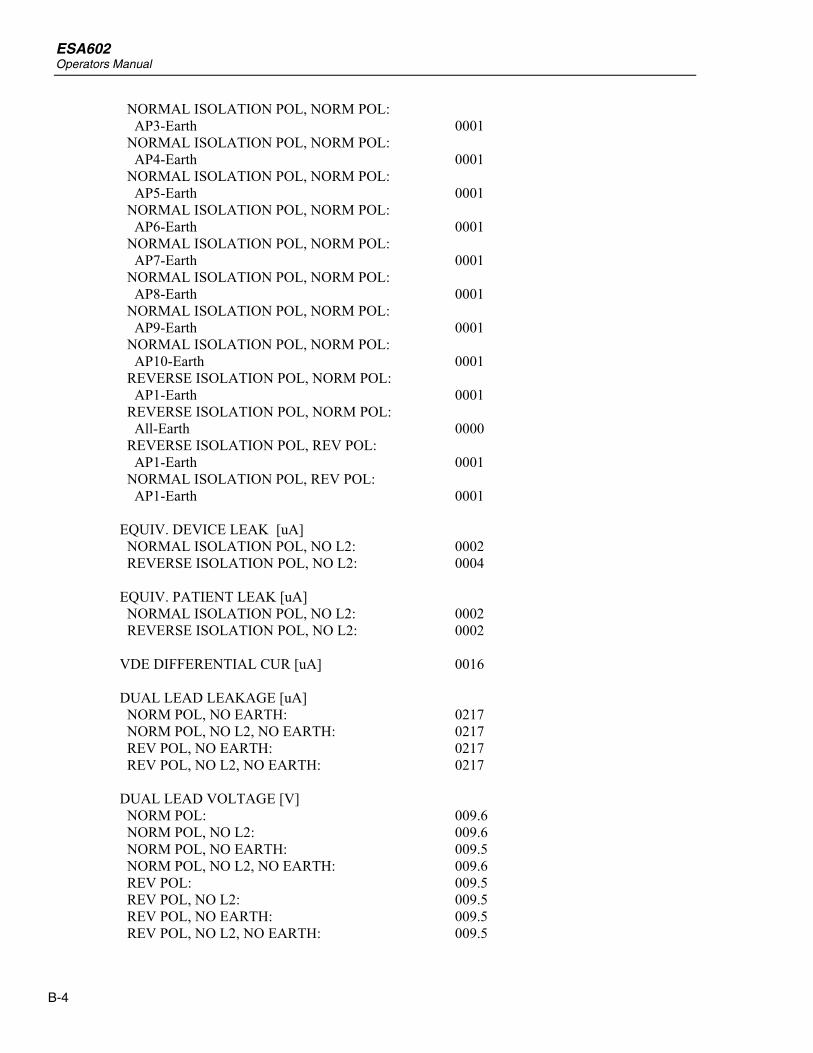
ESA602 Operators Manual
B-4
NORMAL ISOLATION POL, NORM POL: AP3-Earth 0001 NORMAL ISOLATION POL, NORM POL: AP4-Earth 0001 NORMAL ISOLATION POL, NORM POL: AP5-Earth 0001 NORMAL ISOLATION POL, NORM POL: AP6-Earth 0001 NORMAL ISOLATION POL, NORM POL: AP7-Earth 0001 NORMAL ISOLATION POL, NORM POL: AP8-Earth 0001 NORMAL ISOLATION POL, NORM POL: AP9-Earth 0001 NORMAL ISOLATION POL, NORM POL: AP10-Earth 0001 REVERSE ISOLATION POL, NORM POL: AP1-Earth 0001 REVERSE ISOLATION POL, NORM POL: All-Earth 0000 REVERSE ISOLATION POL, REV POL: AP1-Earth 0001 NORMAL ISOLATION POL, REV POL: AP1-Earth 0001 EQUIV. DEVICE LEAK [uA] NORMAL ISOLATION POL, NO L2: 0002 REVERSE ISOLATION POL, NO L2: 0004 EQUIV. PATIENT LEAK [uA] NORMAL ISOLATION POL, NO L2: 0002 REVERSE ISOLATION POL, NO L2: 0002 VDE DIFFERENTIAL CUR [uA] 0016 DUAL LEAD LEAKAGE [uA] NORM POL, NO EARTH: 0217 NORM POL, NO L2, NO EARTH: 0217 REV POL, NO EARTH: 0217 REV POL, NO L2, NO EARTH: 0217 DUAL LEAD VOLTAGE [V] NORM POL: 009.6 NORM POL, NO L2: 009.6 NORM POL, NO EARTH: 009.5 NORM POL, NO L2, NO EARTH: 009.6 REV POL: 009.5 REV POL, NO L2: 009.5 REV POL, NO EARTH: 009.5 REV POL, NO L2, NO EARTH: 009.5

Appendices Sample ESA601 Test Printouts B
B-5
Sample Printout, US-English 2 Version (ESA601-USA) FLUKE BIOMEDICAL DATE:__________________ LOCATION:______________ DEVICE TYPE:___________ MANUFACTURER:__________ SERIAL# :______________ TECHNICIAN:____________ ESA601: Comments: MAINS VOLTAGE [V] 122.4 GROUND WIRE RESISTANCE [OHM] 1.035 INSUL RESISTANCE [MOHM] L1,L2-CASE 095.6 INSUL RESISTANCE [MOHM] LEADS-CASE 099.5 GROUND WIRE LEAKAGE CUR. [uA] NORM POL, NO GROUND: 0001 NORM POL, NO L2, NO GROUND: 0001 REV POL, NO GROUND: 0001 NORM POL, NO GROUND: All-GROUND 0001 NORM POL, NO GROUND: 0001 CHASSIS LEAKAGE CUR. [uA] NORM POL: 0000 NORM POL, NO L2: 0000 NORM POL, NO GROUND: 0000 NORM POL, NO L2, NO GROUND: 0000 REV POL: 0000 REV POL, NO L2: 0000 REV POL, NO L2, NO GROUND: 0000 NORM POL: ALL-GROUND 0000

ESA602 Operators Manual
B-6
LEAD TO GROUND LEAKAGE CUR [uA] NORM POL: RA-GROUND 4686 NORM POL: All-GROUND 4677 RA-GROUND 4682 RL-GROUND 4686 LA-GROUND 4686 LL-GROUND 4687 V1-GROUND 4688 V2-GROUND 4692 V3-GROUND 4692 V4-GROUND 4690 V5-GROUND 4691 V6-GROUND 4693 REV POL: All-GROUND 4654 RA-GROUND 4684 RL-GROUND 4741 LA-GROUND 4738 LL-GROUND 4742 V1-GROUND 4741 V2-GROUND 4745 V3-GROUND 4742 V4-GROUND 4740 V5-GROUND 4738 V6-GROUND 4741 REV POL, NO L2: RA-GROUND 4710 REV POL, NO L2, NO GROUND: RA-GROUND 4728 NORM POL, NO L2, NO GROUND: RA-GROUND 4677 NORM POL, NO L2: RA-GROUND 4651 NORM POL: RA-GROUND 4670 LEAD TO LEADS CURRENT [uA] NORM POL: RA-All 0001 RL-All 0001 LA-All 0001 LL-All 0001 V1-All 0001 V2-All 0001 V3-All 0001 V4-All 0001 V5-All 0001 V6-All 0001 INVALID TEST
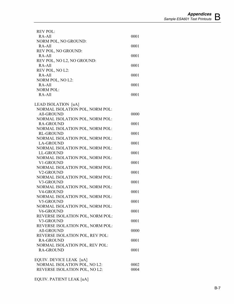
Appendices Sample ESA601 Test Printouts B
B-7
REV POL: RA-All 0001 NORM POL, NO GROUND: RA-All 0001 REV POL, NO GROUND: RA-All 0001 REV POL, NO L2, NO GROUND: RA-All 0001 REV POL, NO L2: RA-All 0001 NORM POL, NO L2: RA-All 0001 NORM POL: RA-All 0001 LEAD ISOLATION [uA] NORMAL ISOLATION POL, NORM POL: All-GROUND 0000 NORMAL ISOLATION POL, NORM POL: RA-GROUND 0001 NORMAL ISOLATION POL, NORM POL: RL-GROUND 0001 NORMAL ISOLATION POL, NORM POL: LA-GROUND 0001 NORMAL ISOLATION POL, NORM POL: LL-GROUND 0001 NORMAL ISOLATION POL, NORM POL: V1-GROUND 0001 NORMAL ISOLATION POL, NORM POL: V2-GROUND 0001 NORMAL ISOLATION POL, NORM POL: V3-GROUND 0001 NORMAL ISOLATION POL, NORM POL: V4-GROUND 0001 NORMAL ISOLATION POL, NORM POL: V5-GROUND 0001 NORMAL ISOLATION POL, NORM POL: V6-GROUND 0001 REVERSE ISOLATION POL, NORM POL: V3-GROUND 0001 REVERSE ISOLATION POL, NORM POL: All-GROUND 0000 REVERSE ISOLATION POL, REV POL: RA-GROUND 0001 NORMAL ISOLATION POL, REV POL: RA-GROUND 0001 EQUIV. DEVICE LEAK [uA] NORMAL ISOLATION POL, NO L2: 0002 REVERSE ISOLATION POL, NO L2: 0004 EQUIV. PATIENT LEAK [uA]

ESA602 Operators Manual
B-8
NORMAL ISOLATION POL, NO L2: 0002 REVERSE ISOLATION POL, NO L2: 0002 VDE DIFFERENTIAL CUR [uA] 0016 DUAL LEAD LEAKAGE [uA] NORM POL, NO GROUND: 0217 NORM POL, NO L2, NO GROUND: 0217 REV POL, NO GROUND: 0217 REV POL, NO L2, NO GROUND: 0217 DUAL LEAD VOLTAGE [V] NORM POL: 009.6 NORM POL, NO L2: 009.6 NORM POL, NO GROUND: 009.5 NORM POL, NO L2, NO GROUND: 009.6 REV POL: 009.5 REV POL, NO L2: 009.5 REV POL, NO GROUND: 009.5 REV POL, NO L2, NO GROUND: 009.5

C-1
Appendix C Equivalent Report Terms
Introduction Table lists the words used in the five different languages of the ESA601.
Table C-1. Language Equivalents for Terms on Report Printouts
ENGLISH IEC TERM
ENGLISH AAMI TERM
FRENCH TERM ITALIAN TERM GERMAN TERM
Language selected “E”
Language selected “E-US”
Language selected “F”
Language selected “I”
Language selected “D”
FLUKE BIOMEDICAL FLUKE BIOMEDICAL FLUKE BIOMEDICAL FLUKE BIOMEDICAL FLUKE BIOMEDICAL DATE DATE DATE DATA DATUM LOCATION LOCATION SERVICE REPARTO STANDORT DEVICE TYPE DEVICE TYPE TYPE D'APP. COSTRUTTORE GERAETETYP MANUFACTURER MANUFACTURER FABRICANT MODELLO HERSTELLER SERIAL# SERIAL# NO.SERIE N.S. SERIEN# TECHNICIAN TECHNICIAN TECHNICIEN TECNICO TECHNIKER ESA601 ESA601 ESA601 ESA601 ESA601 Comments Comments Commentaire Commento Kommentar MAINS VOLTAGE [V] MAINS VOLTAGE [V] TENSION SECTEUR
[V] TENSIONE ALIMETAZIONE [V]
NETZSPANNUNG [V]
DUAL-LEAD VOLTAGE [V]
DUAL-LEAD VOLTAGE [V]
TENSION EXTERNE [V]
TENSIONE DUE FILI [V]
SPANNUNG [V]
DUAL LEAD LEAKAGE [uA]
DUAL LEAD LEAKAGE [uA]
COURANT EXTERNE [uA]
DISPERSIONE A DUE FILI [uA]
STROM [uA]
INSUL RESISTANCE [MOHM]
INSUL RESISTANCE [MOHM]
RES. D'ISOLEMENT [MOHM]
RES. ISOLAMENTO [MOHM]
ISOL.-WIDERSTAND [MOHM]
L1,L2-CASE L1,L2-CASE PH, N -ENVELOPPE. L1,L2-INV. NETZ-GEHAEUSE AP-CASE LEADS-CASE PARTIES APPL. PA. INV ANW. TEILE
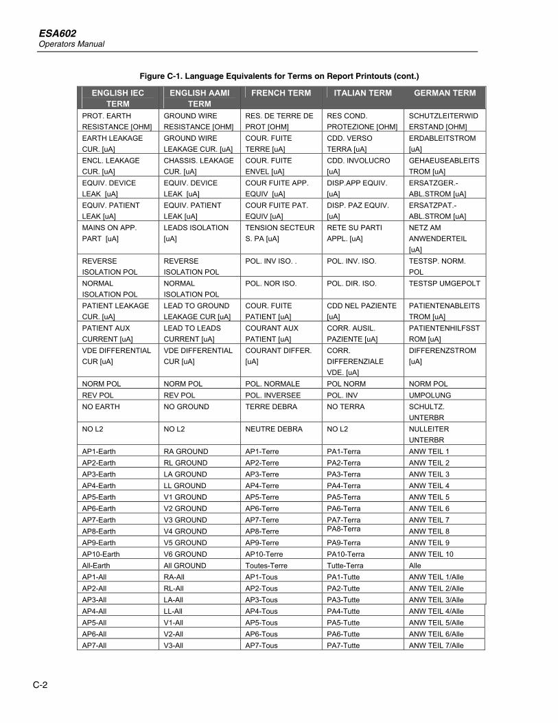
ESA602 Operators Manual
C-2
Figure C-1. Language Equivalents for Terms on Report Printouts (cont.)
ENGLISH IEC TERM
ENGLISH AAMI TERM
FRENCH TERM ITALIAN TERM GERMAN TERM
PROT. EARTH RESISTANCE [OHM]
GROUND WIRE RESISTANCE [OHM]
RES. DE TERRE DE PROT [OHM]
RES COND. PROTEZIONE [OHM]
SCHUTZLEITERWIDERSTAND [OHM]
EARTH LEAKAGE CUR. [uA]
GROUND WIRE LEAKAGE CUR. [uA]
COUR. FUITE TERRE [uA]
CDD. VERSO TERRA [uA]
ERDABLEITSTROM [uA]
ENCL. LEAKAGE CUR. [uA]
CHASSIS. LEAKAGE CUR. [uA]
COUR. FUITE ENVEL [uA]
CDD. INVOLUCRO [uA]
GEHAEUSEABLEITSTROM [uA]
EQUIV. DEVICE LEAK [uA]
EQUIV. DEVICE LEAK [uA]
COUR FUITE APP. EQUIV [uA]
DISP.APP EQUIV. [uA]
ERSATZGER.-ABL.STROM [uA]
EQUIV. PATIENT LEAK [uA]
EQUIV. PATIENT LEAK [uA]
COUR FUITE PAT. EQUIV [uA]
DISP. PAZ EQUIV. [uA]
ERSATZPAT.-ABL.STROM [uA]
MAINS ON APP. PART [uA]
LEADS ISOLATION [uA]
TENSION SECTEUR S. PA [uA]
RETE SU PARTI APPL. [uA]
NETZ AM ANWENDERTEIL [uA]
REVERSE ISOLATION POL
REVERSE ISOLATION POL
POL. INV ISO. . POL. INV. ISO. TESTSP. NORM. POL
NORMAL ISOLATION POL
NORMAL ISOLATION POL
POL. NOR ISO. POL. DIR. ISO. TESTSP UMGEPOLT
PATIENT LEAKAGE CUR. [uA]
LEAD TO GROUND LEAKAGE CUR [uA]
COUR. FUITE PATIENT [uA]
CDD NEL PAZIENTE [uA]
PATIENTENABLEITSTROM [uA]
PATIENT AUX CURRENT [uA]
LEAD TO LEADS CURRENT [uA]
COURANT AUX PATIENT [uA]
CORR. AUSIL. PAZIENTE [uA]
PATIENTENHILFSSTROM [uA]
VDE DIFFERENTIAL CUR [uA]
VDE DIFFERENTIAL CUR [uA]
COURANT DIFFER. [uA]
CORR. DIFFERENZIALE VDE. [uA]
DIFFERENZSTROM [uA]
NORM POL NORM POL POL. NORMALE POL NORM NORM POL REV POL REV POL POL. INVERSEE POL. INV UMPOLUNG NO EARTH NO GROUND TERRE DEBRA NO TERRA SCHULTZ.
UNTERBR NO L2 NO L2 NEUTRE DEBRA NO L2 NULLEITER
UNTERBR AP1-Earth RA GROUND AP1-Terre PA1-Terra ANW TEIL 1 AP2-Earth RL GROUND AP2-Terre PA2-Terra ANW TEIL 2 AP3-Earth LA GROUND AP3-Terre PA3-Terra ANW TEIL 3 AP4-Earth LL GROUND AP4-Terre PA4-Terra ANW TEIL 4 AP5-Earth V1 GROUND AP5-Terre PA5-Terra ANW TEIL 5 AP6-Earth V2 GROUND AP6-Terre PA6-Terra ANW TEIL 6 AP7-Earth V3 GROUND AP7-Terre PA7-Terra ANW TEIL 7 AP8-Earth V4 GROUND AP8-Terre PA8-Terra ANW TEIL 8 AP9-Earth V5 GROUND AP9-Terre PA9-Terra ANW TEIL 9 AP10-Earth V6 GROUND AP10-Terre PA10-Terra ANW TEIL 10 All-Earth All GROUND Toutes-Terre Tutte-Terra Alle AP1-All RA-All AP1-Tous PA1-Tutte ANW TEIL 1/Alle AP2-All RL-All AP2-Tous PA2-Tutte ANW TEIL 2/Alle AP3-All LA-All AP3-Tous PA3-Tutte ANW TEIL 3/Alle AP4-All LL-All AP4-Tous PA4-Tutte ANW TEIL 4/Alle AP5-All V1-All AP5-Tous PA5-Tutte ANW TEIL 5/Alle AP6-All V2-All AP6-Tous PA6-Tutte ANW TEIL 6/Alle AP7-All V3-All AP7-Tous PA7-Tutte ANW TEIL 7/Alle

Appendices Equivalent Report Terms C
C-3
Figure C-1. Language Equivalentsfor Terms on Report Printouts (cont.)
ENGLISH IEC TERM
ENGLISH AAMI TERM
FRENCH TERM ITALIAN TERM GERMAN TERM
AP8-All V4-All AP8-Tous PA8-Tutte ANW TEIL 8/Alle AP9-All V5-All AP9-Tous PA9-Tutte ANW TEIL 9/Alle AP10-All V6-All AP10-Tous PA10-Tutte ANW TEIL 10/Alle INVALID TEST INVALID TEST ESSAI
INADMISSIBLE PROVA NON VALIDA UNZULAESSIGER
TEST

ESA602 Operators Manual
C-4

D-1
Appendix D Abbreviations
Abbreviations A ampere
AAMI American Association of Medical Instrumentation
AP applied parts
CTS clear to send
dB decibel
DCE data communication equipment
DTE data terminal equipment
DUT device under test
Hz hertz
IEC International Electrotechnical Commission
kHz kilohertz
LA left arm
LED light-emitting diode
LL left leg
MΩ megohm
M.A.P. / MAP Mains on applied parts
MHz megahertz
MΩ megohm
PCBA printed circuit board assembly
PE Protective Earth
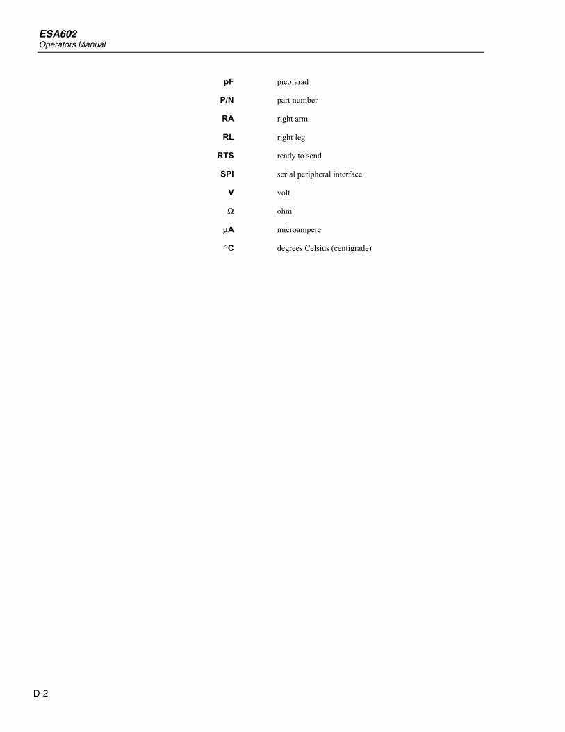
ESA602 Operators Manual
D-2
pF picofarad
P/N part number
RA right arm
RL right leg
RTS ready to send
SPI serial peripheral interface
V volt
Ω ohm
µA microampere
°C degrees Celsius (centigrade)