![[0411-2010-ED]-[31-03-2014 11_33_04]-RM 0411-2010-ED0001](https://static.fdocuments.us/doc/165x107/563dbb28550346aa9aaac129/0411-2010-ed-31-03-2014-113304-rm-0411-2010-ed0001.jpg)
ESA - GSP-RPT-NPS-0411...In conclusion, this program concerns a preliminary feasibility study of a...
110
POLITECNICO DI MILANO DIPARTIMENTO DI INGEGNERIA NUCLEARE 2003.12.12 Page 1 / 110 Study on Nuclear Space Reactor Development (SURE) ESTEC Contract N° 1730/030NL/LvH CESNEF-IN-03-12/01 ESTEC CONTRACT NUMBER 1730/03/NL/LvH STUDY ON NUCLEAR SPACE REACTOR DEVELOPMENT (SURE) Dipartimento di Ingegneria Nucleare Politecnico di Milano
Transcript of ESA - GSP-RPT-NPS-0411...In conclusion, this program concerns a preliminary feasibility study of a...
POLITECNICO DI MILANO DIPARTIMENTO DI INGEGNERIA NUCLEARE
2003.12.12 Page 1 / 110
Study on Nuclear Space Reactor Development (SURE)
ESTEC Contract N° 1730/030NL/LvH CESNEF-IN-03-12/01
ESTEC CONTRACT NUMBER 1730/03/NL/LvH
STUDY ON NUCLEAR SPACE REACTOR DEVELOPMENT (SURE)
Dipartimento di Ingegneria Nucleare Politecnico di Milano

POLITECNICO DI MILANO DIPARTIMENTO DI INGEGNERIA NUCLEARE
2003.12.12 Page 2 / 110
Study on Nuclear Space Reactor Development (SURE)
ESTEC Contract N° 1730/030NL/LvH CESNEF-IN-03-12/01
Staff Personnel
Prof. Carlo Lombardi Prof. Marco Ricotti Ing. Enrico Padovani, PhD Ing. Elvina Finzi, PhD student Ing. Matteo Passoni, PhD student Ing. Silvia De Grandis, Laurea Degree Ing. Lorenzo Santini, Laurea Degree Diego Mandelli, student

POLITECNICO DI MILANO DIPARTIMENTO DI INGEGNERIA NUCLEARE
2003.12.12 Page 3 / 110
Study on Nuclear Space Reactor Development (SURE)
ESTEC Contract N° 1730/030NL/LvH CESNEF-IN-03-12/01
INDEX INDEX 3 EXECUTIVE SUMMARY 5 FOREWORD 20 1 INTRODUCTION 25
2 THE PWR 27
2.1 INTRODUCTION 27
2.2 NEUTRONIC DESIGN 32
2.2.1 Design codes 32 2.2.2 WIMS and Monte Carlo comparison 33 2.2.3 Core design 39
2.3 ELECTRICAL POWER GENERATION SYSTEM 42
2.3.1 The Rankine cycle 43 2.3.2 Organic fluid Rankine cycle 43
2.4 THE PRIMARY SYSTEM 45
2.4.1 The reactor vessel 46 2.4.2 The steam generator 48 2.4.3 The pressurizer 51 2.4.4 The circulating pump 52
2.5 THE REACTIVITY CONTROL 55
2.6 THE COLD WELL 61
2.7 MASSES 64
2.8 PRELIMINARY SAFETY CONSIDERATIONS 66
2.9 OPEN ISSUES AND R&D NEEDS 69
2.10 CONCLUDING REMARKS 70
2.11 PWR REACTOR LIST OF DATA 72
3 THE HTGR 76
3.1 INTRODUCTION 76
3.2 NEUTRONIC DESIGN 78

POLITECNICO DI MILANO DIPARTIMENTO DI INGEGNERIA NUCLEARE
2003.12.12 Page 4 / 110
Study on Nuclear Space Reactor Development (SURE)
ESTEC Contract N° 1730/030NL/LvH CESNEF-IN-03-12/01
3.2.1 Design codes 78 3.2.2 WIMS and Monte Carlo comparison 79 3.2.3 Core design 83
3.3 ELECTRICAL POWER GENERATION BY THE BRAYTON CYCLE 86
3.4 ELECTRICAL POWER GENERATION BY THE THERMOELECTRIC DEVICE 88
3.5 THE PRIMARY SYSTEM 94
3.5.1 The pressure vessel 98 3.5.2 The regenerator 98
3.6 THE REACTIVITY CONTROL 99
3.7 MASSES 100
3.8 PRELIMINARY SAFETY CONSIDERATIONS 100
3.9 OPEN ISSUES AND R&D NEEDS 102
3.10 CONCLUDING REMARKS 103
3.11 HTGR REACTOR LIST OF DATA 104
4 COMPARISON BETWEEN THE TWO PROPOSALS 107 References 109 APPENDIX A A1

POLITECNICO DI MILANO DIPARTIMENTO DI INGEGNERIA NUCLEARE
2003.12.12 Page 5 / 110
Study on Nuclear Space Reactor Development (SURE)
ESTEC Contract N° 1730/030NL/LvH CESNEF-IN-03-12/01
Executive summary
Foreword. Ambitious solar system exploration missions in the near future will require robust space power sources in
the range of 10 to 200 KWe. Fission power systems are well suited to provide safe, reliable, and
economic power within this range. Therefore the goal of this research program is to carry out a
preliminary feasibility study of a nuclear fission reactor suited for space applications. These refer either to
rocket propulsion by electricity (NEP: Nuclear Electric Propulsion) or to electrical power production for
stationary settlements (manned or unmanned) on some planet (Mars), or deep space planetary surfaces,
or satellites (Moon).
This application of nuclear energy is very demanding and it should be addressed in a gradual way,
because numerous space fission power programs failed having tried to do too much too soon. Thus a
good option for developing the reactor-related portion of this infrastructure and experience is to start by
developing and utilizing a low-power surface fission power system: surface applications generally place
less demanding requirements on the reactor and integrated system. Even if this study concerns both
applications, the solutions envisaged better apply to surface applications.
The present study is a preliminary one, which in principle cannot have the ambition to give a priori a well
definite answer to the problem, in the sense to reach by certain a viable proposal fit for a subsequent
specific R&D program. A space nuclear reactor should respond to the following general requirements:
1. To be extremely reliable;
2. To imply an R&D program of moderate cost;
3. To be deployed within a reasonable period of time;
4. To be operated and controlled for a long time without intervention;
5. To be able to be transported into space (mass and size limit)
6. To be also used as a byproduct for some particular terrestrial application (or at least to share
common technologies).
The first three items mean that the chosen reactor type must be extensively and positively tested in
terrestrial applications, thus too innovative proposals are a priori excluded, at least in the medium period.
Item 4) is important and again in favor of simple and reliable solutions. Item 5) is quite obviuos.
Item 6) is motivated by the usefulness to have an economic return of R&D costs from other non space
applications of the same reactor concept, in fact it seems possible and probable that some technologies
needed for space reactors have a terrestrial application in nuclear and non nuclear systems.
All the above considerations taken into account, it can be concluded that this reactor type should be:
• Based on the well proven technology of present terrestrial reactors, allowing obviously the
development of different components and systems needed to accomplish the specific mission of
a space reactor, according to known processes,
• Suitable for propulsion and stationary applications, apart from reasonable and moderate
differences.

POLITECNICO DI MILANO DIPARTIMENTO DI INGEGNERIA NUCLEARE
2003.12.12 Page 6 / 110
Study on Nuclear Space Reactor Development (SURE)
ESTEC Contract N° 1730/030NL/LvH CESNEF-IN-03-12/01
If these conclusions are accepted in this context, the first result is that the propulsion reactor has to
produce electricity, in the same way as the stationary one, and its electricity will be used for propulsive
scopes, by adopting suitable converting apparatus downstream the reactor.
A space reactor must satisfy a number of requirements, besides the general ones presented above. A
non exhaustive list is as follows:
- produce an electrical power around 100 KW;
- last a long period of time (around 4000 days) without any intervention and fuel supply;
- minimize the overall mass and volume for rocket payload constraints;
- use high enriched uranium;
- adopt a core power density substantially lower than current reactors;
- satisfy the usual safety requirements of terrestrial reactors and besides this to assure:
- no irradiated fuel is present at launch;
- the core subcriticality in the case of all possible launch accidents (flooding);
- the radiation protection without impairing weight requirements;
- an easy decommissioning in space;
- a simple control of the reactor and the overall plant;
- a substantial reduction and simplification of maintenance and repairs;
- avoid any leakage of the contained fluids or implement systems to recuperate them;
All taken into account two reactor types are here considered: PWR and HTGR. The PWR (Pressurized
Water Reactors) is the most common reactor type for terrestrial power stations and widely used for
submarines propulsion: the features of space reactors are more similar, in relative sense, to those of
naval reactors than those of civilian reactors, and this can be seen as a significant starting point. The
HTGR (High Temperature Gas Reactors) has the peculiar feature to generate heat at much higher
temperatures than PWRs, typically 800-900 °C against 300 °C. This means higher thermodynamic
efficiencies and the possibility to widen the nuclear energy exploitation to other industrial applications
different from electricity production. However, the experience acquired up to now, even if significant, is
not comparable at all to that of PWRs; in fact important R&D programs are under way in the world.
In conclusion, this program concerns a preliminary feasibility study of a space reactor, suited either for
stationary needs on a planet or for propulsion, to produce electrical energy of the order of 100 KW. It will
be articulated in the following steps:
- Assume as a first choice the PWR solution as the reference system.
- Execute a rather detailed neutronic study of this reactor, which is two orders of magnitude smaller
than conventional reactors (the power is three order of magnitude lower, but the power density is an
order of magnitude lower).
- Define the preliminary scheme of the whole plant, under alternative solutions for electricity
production: adoption of thermoelectric device or simplified conventional generators.
- Put in evidence the differences between propulsion and stationary reactor specifications and the way
to fulfil them.

POLITECNICO DI MILANO DIPARTIMENTO DI INGEGNERIA NUCLEARE
2003.12.12 Page 7 / 110
Study on Nuclear Space Reactor Development (SURE)
ESTEC Contract N° 1730/030NL/LvH CESNEF-IN-03-12/01
- Carry out analyses for a preliminary verification of its capability to satisfy the requirements listed
above for a space reactor.
- Analyzing the HTGR reactors, outlining pros and cons of these reactors when compared to PWRs.
- Make a survey of Italian industry capability and willingness to participate to the development of such
a reactor.
- Verify the potentialities of space reactors for particular terrestrial uses.
- Identify a research and development program including the aspects of interest for civilian (industrial)
purposes in Europe;
- Draw the conclusion of the whole activity.
Introduction
Initially, a conspicuous number of analyses starting from neutronic calculations, and thus those about
generator efficiency, cold well sizing, circuit definition, control, etc. were carried out. The target was to
focus the main aspects of the system and to yield indications for a motivated choice of the main
specifications for the final study. This was a demanding and time consuming activity; however this
surveying activity will not be described in this document. The fuel enrichment is an important issue: the
higher its value the lower the size and the mass of the reactor. However, the proliferation comes in, in
the sense that uranium up to 20 % enrichment is not usable for a bomb, while uranium with 93 %
enrichment is the “best” fuel for this military use. It is well known that the Nuclear Powers, led by USA,
are against any action, which facilitates nuclear “proliferation”. This the reason why a significant fraction
of our calculations referred to this 20 % enrichment. Approaching the end of the work it became clear
that the proliferation political constrain was too heavy to be maintained, because of its design penalty,
and by agreement with our technical interface the 20 % enriched fuel solution has been dropped.
The report is divided in three chapters and an appendix: the first chapter devoted to PWR, the second to
HTGR. These chapters start from the neutronic calculations to define the reactor core, then pass to the
electrical generator, the primary system, the reactivity control, the cold well. Successively a list of open
issues and a preliminary indication on the potential R&D program required, the conclusions of the
feasibility study and the complete list of data. The third chapter is a synthetic comparison between the
two systems. The appendix details the results of the Italian industry inquiry.

POLITECNICO DI MILANO DIPARTIMENTO DI INGEGNERIA NUCLEARE
2003.12.12 Page 8 / 110
Study on Nuclear Space Reactor Development (SURE)
ESTEC Contract N° 1730/030NL/LvH CESNEF-IN-03-12/01
The PWR
The idea is to extend as much as possible the PWR technology adopted for producing high powers in
terrestrial applications to the design of a reactor suited for space conditions. However a number of
modifications are needed. Let us summarize them.
Fuel composition: conventional powder of 93 % enriched uranium oxide, sintered in very small pellets.
Pellet diameter: the chosen value is 1.8 mm, four times lower than the smallest current pellet.
Fabrication process is to be defined. Cladding material: Stainless steel. Cladding thickness: 0.2 mm.
Fuel rod size: the outer diameter is 2.2 mm, while the length is a design parameter, because it results
from the core size, which is a cylinder with the diameter equal to the height. Fuel bundle: 19 rods are
assembled in hexagonal geometry, and inserted in a hexagonal stainless steel shroud with a thickness of
0.3 mm. Fuel burnup: an average initial value of 60 MWd/kgU (maximum value) is assumed, which is
about the same value presently adopted in PWRs.
Temperatures and pressures: the maximum operating pressure is assumed identical to PWRs, i.e. 15.5
MPa. The maximum temperature is set equal to the saturation value: 345 °C, which is about 15 °C higher
than that of PWRs, while minimum temperature at the inlet is assumed equal to 335 °C, which is 45 °C
higher than that of PWRs.
Cold well temperature: lower temperature means higher efficiencies, but higher cold well size: a
temperature of 165 °C is a reasonable trade off between these opposite requirements.
Electrical generator: three alternate designs are considered i.e.: thermoelectric generator, Rankine
steam cycle, Rankine organic fluid cycle. The thermoelectric generator has been discarded in this case,
because the relatively small temperature difference between average core temperature and cold well
temperature gives too low efficiencies, around 2-3 %. The other two cycles are characterized by an
efficiency equal to 12.5 % and 18 % respectively. This leads to two values of thermal power equal to 800
KW and 555 KW.
Minimum fuel quantity: set the thermal power, the burnup, the full power duration (4000 days), we
obtain for the above thermal powers the following minimum uranium masses: 53.3 and 37.0 kg
respectively. This is equivalent to have a maximum fuel power density of 13.2 KW/kgUO2, which is lower
than that of conventional PWRs (38 KW/kg), while the linear power rate is much lower 0.39 against 17.8
KW/m.
Core geometry and reflector: the core geometry is based on the assumption to have a cylinder with the
diameter equal to the height. The reflector is a layer of 12 cm of water all around the core.
Primary pumps: the industry has in advanced stage of development the technology of “spool pumps”,
which can be fully inserted in the primary circuit without any seal, because the motor can operate at high
temperature inside the coolant.
Neutronic design. The program WIMS (Winfrith Improved Multi group Scheme) is a deterministic
computation program, which uses a wide variety of calculation methods to solve the reactor physics
problems. WIMS gives the reactivity in an infinite mean, thus, to obtain the reactivity of a finite reactor, it
requires in input the values of axial and radial buckling, which is a crucial parameter in this small size

POLITECNICO DI MILANO DIPARTIMENTO DI INGEGNERIA NUCLEARE
2003.12.12 Page 9 / 110
Study on Nuclear Space Reactor Development (SURE)
ESTEC Contract N° 1730/030NL/LvH CESNEF-IN-03-12/01
reactor. As the effective multiplication factor strongly depends on the buckling values introduced in input,
it seemed important to compare the results obtained by WIMS with those of a Monte Carlo program,
which can be considered as an exact program. The comparison was made in four specific points and
namely: infinite lattice and actual reflected reactor at Beginning of Life, in cold and hot conditions and by
varying the moderation ratio. The Monte Carlo code here used is the well known MCNP-4C, as distributed
by NEA Data Bank. The comparison turned out positive (see Figs 2.7 and 2.9), giving an indication that
the WIMS should converge at the End of Life to a keff = 1.000.
The neutronic design suggested to reduce slightly the above determined minimum fuel mass for the 800
KW core, for a the moderation ratio of 6.5; for the 555 KW core the fuel mass is equal to the above
mentioned value and the moderation ratio is 7 (see Figs 2.11 and 2.12). Figures 2.13 and 2.14 show the
final fuel channel disposition in the 800 KW and 555 KW case, respectively. It is interesting to note that
the core size is not much different for the two required powers.
The primary system. The primary system is made by the reactor vessel which contains the reactor core,
the barrel, the steam generator, the pressurizer, the circulating pump, the safety valve, the reactivity
control mechanism and the instrumentation. All these components are inside the reactor vessel, adopting
the so called integrated layout. This allows to keep the size and the mass of the primary system to a
minimum. Water flows upward through the core and then through the lower part of the upper plenum (the
remaining part is filled with steam for the pressurizer), where the flow direction is reversed and the
coolant is directed downward through the annular downcomer region, between the core barrel and the
vessel; in this annular space the steam generator is located; the primary water flows on the outer surface
of the steam generator tube, exchanging heat with the secondary fluid (water or organic compound) till
the lower plenum, where the suction of the circulating pump is located; then the pumped coolant enters
the reactor core to close the circuit (see Figs. 2.22-23 for the layout of the primary system).
The vessel shape is a cylinder with hemispheric domes (see Figs 2.18, 2.19, and 2.20), made of steel.
The steel recently adopted for PWR vessels has an allowable stress of 205 MPa. By using this value the
thickness are calculated, which are approximately equal to 29 mm and 14.5 mm for the cylindrical portion
and the spherical domes for both powers.
The barrel is a simple steel cylinder not undergone to any particular load. Its thickness is determined by
the requirement to have a good rigidity and to reduce fast fluence on the vessel if necessary: a value of
15 mm has been assumed.
The steam generator design here proposed is different from the usual one, the main difference being that
all the sensible components inside the pressure vessel - i.e. tubes, headers and nozzles crossing the
pressure vessel wall - are compressed instead of being stretched, because the higher primary pressure is
acting on the outer surfaces: strictly speaking, primary stresses are compressive. This means that
deterioration mechanisms due to high stresses, such as fatigue, should inherently be eliminated. Taking
into account the limited power to be transferred in this case, it has been decided to adopt a single tube in
order to eliminate any instability phenomena due to parallel channels. This would imply to choose a
reasonable high value of the diameter and the length of the tube. The design results seem well within the

POLITECNICO DI MILANO DIPARTIMENTO DI INGEGNERIA NUCLEARE
2003.12.12 Page 10 / 110
Study on Nuclear Space Reactor Development (SURE)
ESTEC Contract N° 1730/030NL/LvH CESNEF-IN-03-12/01
existing experience, especially as far as the length and the secondary pressure drops are concerned.
However the thermalhydraulic behavior of helix was not well studied in past; an experimental campaign is
needed for its development, also to take into account the effect of lack or reduced gravity.
For organic fluid there are differences, which probably are self compensating, so that the overall SG
surface may result almost equal to the water one.
The pressurizer is a rather complex system, which can be simplified by putting the pressurizer in direct
connection to the vessel (in the upper dome in our case) and bringing the outlet temperature to the
saturation value, as here done. An abundant free steam volume, as 30 liters per MW, which is several
times the value used in conventional PWRs, is adopted. This means in our case 24 and 17 liters for 800
and 555 KW reactors respectively. The water spray is then eliminated. These volumes are only a fraction
of the upper sphere volume, which is equal to about 90 liters. Besides this free volume we have to
foresee the possibility to contain the water expansion between cold and hot conditions; in fact the specific
volume increases by a factor 1.64, going from ambient temperature (on the earth) to the average reactor
temperature of 340 °C. This means that there are two alternatives: discharge the excess of water to an ad
hoc vessel or to leave a initial void inside the cold vessel exactly equal to the above volume difference.
The circulating pump is of the spool type, which has been used in marine applications and designed for
chemical plant applications requiring high flow rates and low developed head. The motor and pump
consist of two concentric cylinders, where the outer ring is the stationary stator and the inner ring is the
rotor, that carries high specific speed pump impellers (see Fig 2.21). The spool pump is located entirely
within the reactor vessel; only small penetrations for the electrical cables are required. High temperature
windings and bearing materials are under development.
The reactivity control. The PWR has inherently favorable features for control requirements, since it is
characterized by a negative reactivity coefficient of temperature, which makes the reactor a load follower.
In particular, in this reactor the temperature coefficient is still higher than in PWRs: approximately -300
against -30 pcm/°C. The overall reactivity to be controlled is about 28000 pcm against 24000 of current
PWRs. The differences between PWR and this reactor are due to the high enrichment and to a reduced
extent for the low power density. The control of this reactivity excursion is not an easy task. In this reactor
the leakage of neutrons is so high, that a reflector poisoning may be enough to reduce the reactivity. This
is to be thorough by verified. If this is the case, the control rods can be imagined not going up and down
into the reflector, but made by a rotating cylinder, having on its diameter the poison plate. The rotation
varies the angle of the poison plate, and then its neutron absorption capability. Here a different proposal
is put forward: the principle is shown in Fig. 2.24 and 2.25: the core is divided in six moving slices each
having a mass grossly of20 kg, operated by a single mechanism (to be defined). The specification is that
by moving apart the slices in outside direction up to a maximum equal to the thickness of the reflector, the
reactivity decreases slowly to a minimum equal to that required for the overall control. WIMS and Monte
Carlo calculations show that the reactivity first rises, because the core is under moderated, then reaches
a maximum and afterwards goes down rapidly: at 12 cm of distance the reactor is no longer critical.

POLITECNICO DI MILANO DIPARTIMENTO DI INGEGNERIA NUCLEARE
2003.12.12 Page 11 / 110
Study on Nuclear Space Reactor Development (SURE)
ESTEC Contract N° 1730/030NL/LvH CESNEF-IN-03-12/01
The cold well. It is one of the most crucial component of any thermodynamic cycle for space application .
Referring to the solution adopting the steam Rankine cycle with a power of 800 KW and a net efficiency of
12.5 %, the thermal power to be dissipated in the condenser is 700 KW. For the time being, only radiation
has been considered. In a preliminary optimization study the conclusion was reached that the optimum
condenser temperature for minimizing the overall mass is around 165 °C. By assuming a tentative view
factor equal to 0.6 and a back radiation of an average temperature of 300 K, the specific surface results
to 1.14 m2/KW and then a total surface of 796 m2. The condenser geometry is made by a bundle of 464
titanium tubes of ID/OD = 6/6.84 mm connected in parallel, having an overall weight of 1840 kg. The
condenser can be imagined as a cylinder of 8 m diameter and 10 m height. In the case of organic
Rankine cycle the power to be dissipated is 455 KW. Thus, adopting the same tubes, the condenser
would be a cylinder of 5.3 m diameter and 10 m height.
Figs. 2.29 and 2.30 show a simplified scheme and the layout of the plant for the 800 KW reactor,
respectively.
Preliminary safety considerations. A detailed safety analysis is outside the scope of this feasibility
study, for its complexity and need to define the detailed requirements. In fact this reactor from one side is
nor subjected to the licensing procedure of terrestrial reactors imposed by the safety authorities, from the
other it must satisfy specific safety issues connected to its launch and the possibility to fall down to the
earth:
- no irradiated fuel is present at launch;
- the core subcriticality in the case of possible launch accidents (flooding);
- the radiation protection without impairing mass requirements;
- an easy decommissioning in space.
The first item is inherently satisfied, because the reactor would not reach its first criticality before being
outside terrestrial space. The second one seems inherently satisfied because a water reactor cannot be
flooded. The third is a an important issue, which can be addressed only after having defined some
conditions, especially for the propulsion solution. The fourth one is too indefinite at this stage of the
design, that no specific consideration can be drawn.
In this study, a calculation has been done to verify whether in the case of severe accidents the fuel
melting is avoided. If the fuel is no longer cooled by the water, the fuel heats up adiabatically till it
reaches its melting point. However, as soon as the fuel temperature rises, a thermal radiation process
takes place, the importance of which increases rapidly with the temperature. This radiation power is
exchanged among the rods inside the core and from the outer rods ring toward the vessel and then from
the latter toward the outside environment. Besides the radiation, there is also the convection of steam or
air, which flowing inside the hot core brings its heat to the vessel walls and from them to the outside
world. It is really difficult to simulate this situation by a model. A rather simplified but sufficiently realistic
one has been prepared, limiting conservatively the study only to the radiation process. The results show
that the maximum temperature is far from the melting point of stainless steel (1700 K) and even more

POLITECNICO DI MILANO DIPARTIMENTO DI INGEGNERIA NUCLEARE
2003.12.12 Page 12 / 110
Study on Nuclear Space Reactor Development (SURE)
ESTEC Contract N° 1730/030NL/LvH CESNEF-IN-03-12/01
from that of uranium oxide (3000 K). However, this analysis should be improved in the future to take into
account the shrouds, the radial and axial flux distribution and the effect of rod pitch.
Open issues and R&D needs. This feasibility study has allowed us to find a first list of open issues to be
solved for going on this route, which need a R&D program. The issues here below written in bold letters
are those interesting for terrestrial reactors and those written in italic those interesting for generic
terrestrial applications as well.
- Fuel
- Internals: mechanical design;
- Increase of operating pressure: fuel implications, primary circuit materials;
- Saturation temperature at the reactor outlet: effect of small boiling inside the core;
- The cold well as condenser;
- Small steam turbines;
- Organic fluids: type, stability, thermal transport capabilities; Small organic fluid turbine;
- Fluid leakage: how much, how to cope with;
- Maintenance requirements of the whole system;
- Optimum reflector: technological aspects
- Pumps: development of spool pumps, reliability for long periods;
- Fluence effects on vessel in these particular conditions;
- Shielding;
- Safety valves: reliability, how to cope their intervention;
- Vessel material different from stainless steel;
- Steam Generator thermalhydraulic behavior in helical geometry also in presence of low or
no gravity;
- Corrosion deposits inside the SG tube;
- The pressurizer: self pressurization, different concepts for propulsion reactor as feed and
bleed, cold pressurizer, centrifugal action;
- Control of the system and of the reactor and its constructive implications.
Even if this list is incomplete, no item seems to be unsolvable. An R&D program of reasonable extent
may yield the needed answers, but what is important that the most demanding researches also are of
interest for the new generation Light Water Reactors. Thus a cost sharing action can be proposed and
duly programmed, according to the time schedule of the commercial exploitations of these terrestrial
reactors.
Concluding remarks. At the end of this very preliminary feasibility study about the use of PWR system
for space reactors, it can be concluded that no insoluble issues have been evidenced, which would
prevent of going on along this route in order to execute a more detailed design. Then it will be possible to
draw a more justified conclusion about the usefulness to follow this solution. At the beginning of the study
it was supposed that the solutions for propulsion and surface application might be the same. However,
this hypothesis holds only partially, because the lack of gravity and of a soil render the propulsion solution

POLITECNICO DI MILANO DIPARTIMENTO DI INGEGNERIA NUCLEARE
2003.12.12 Page 13 / 110
Study on Nuclear Space Reactor Development (SURE)
ESTEC Contract N° 1730/030NL/LvH CESNEF-IN-03-12/01
rather different and more demanding than the surface one. In particular, two aspects have been outlined
for propulsion reactors: the lack of steam water separation in case of lack of gravity (pressurizer, steam
moisture separation), and the need of an autonomous radiation shield, which in surface reactors can be
provided by the existence of a soil. On the other side, it was anticipated in the foreword that the use of
space nuclear reactors should be approached gradually starting from the easiest application, which is that
for surface use: this study is a confirmation of the statement.
In the short range, future design activities should address the detailing of many aspects of the analysis
presented in this report and adding new ones. Among the first ones, concerning the core, the choices to
limit the fuel burnup, the use of stainless steel instead of zircaloy for cladding and shroud, the reflector
material should be reconsidered: in fact these conservative choices affect the reactor size, which is an
important item to define the overall mass. While for the rest of the system: cold well (in forced convection
as well), reactivity and plant control. The new activities are: radiation shielding, vessel fluence, safety
aspects, choice of vessel material, overall layout, containment, leakage control, ancillary circuits for start
up, coolant purification, radiolisis. and other exigencies. Moreover, at the end of this further activity a
preliminary R.& D. program should be detailed.
The complete list of the obtained data for the PWR reactor is detailed in the final table of par. 2.11.
The HTGR
The idea is to extend as much as possible the HTGR technology adopted for producing high powers in
terrestrial applications to the design of a reactor suited for space conditions. However a number of
modifications are needed. Let us summarize them.
Fuel: conventional powder of 93 % enriched uranium oxide, sintered in micro spheres of 350 µm
diameter. Cladding material and thickness: the fuel micro spheres are protected by four carbon based
layers of overall thickness equal to 400 µm and then the outer diameter turns out to be 750 µm. Fuel
“rod”, said compact: the micro spheres are mixed with a graphite powder and then compacted to form
an hexagonal rod or compact having the apothem of 3.8 mm, while the length is that of the reactor height
and thus it is the result of the neutronic calculations to define the core size. Fuel-moderator-coolant
channels: the moderator is graphite under the form of hexagonal blocks having the same length of the
reactor height. The blocks have an apothem which depends on the moderation ratio. The blocks are
drilled by hexagonal holes: six of them are for the compacts and one for the coolant (Fig. 3.1). The
blocks are then assembled together to form the reactor core. Fuel burnup: an average value of 100
MWd/kgU (maximum value) is assumed, which is about the same value presently adopted in HTGRs.
Temperatures and pressures: the maximum and the minimum temperatures are in both case 900/735
°C respectively. The minimum pressure is the usual value of 3 MPa, while the maximum one depends on
the optimum compression ratio (1.6 in the chosen cycle, giving a maximum pressure of 4.8 MPa). Cold well temperature: in this case the choice depends on the generator type adopted.
Electrical generator: two alternate designs are possible i.e.: thermoelectric generator, the Brayton gas
cycle. The thermoelectric generator is a possible and interesting solution in this case, thanks to the

POLITECNICO DI MILANO DIPARTIMENTO DI INGEGNERIA NUCLEARE
2003.12.12 Page 14 / 110
Study on Nuclear Space Reactor Development (SURE)
ESTEC Contract N° 1730/030NL/LvH CESNEF-IN-03-12/01
relatively high temperatures. In fact a net efficiency of 4.5 % has been calculated (see details below).
Thus for obtaining 100 KWe net power, the reactor thermal power is to be 2219 KWth. The direct Brayton
gas cycle is characterized by a much higher net efficiency equal to 24 %. This leads to a value of thermal
power equal to 417 KW.
Minimum fuel quantity: set the thermal power, the burnup, the full power duration (4000 days), the
following minimum UO2 fuel masses are: 100 and 20 kg of UO2 respectively. The possibility to adopt the
above minimum masses is strictly connected to the reactor neutronic design. Present calculations show
that the minimum mass for the 417 KW does not minimize the overall reactor mass and it is to be
increased to 100 kg UO2 as well; this means that the maximum fuel burnup is much lower in this case and
this can be positive for a better fuel performance. Core geometry and reflector: the core geometry is
based on the assumption to have a cylinder with the diameter equal to the height. The reflector is a layer
of 5 cm of graphite all around the core.
Turbine and compressor: these are two important components of the generator, which should undergo
a thorough verification for these small sizes and high reliability needed for long period of time operating at
very high temperature. In particular the gas leakage raises some concern, because if present, even if to a
reduced extent, would determine big impacts on the system design: containment, reinsertion in the circuit
at high pressure. This concern has been coped with in this study by the decision to put all the rotating
machines inside the pressure vessel.
Neutronic design. In this case the WIMS (Winfrith Improved Multi group Scheme) calculation program
has been used, as already done for the PWR solution. As the effective multiplication factor strongly
depends on the buckling values introduced in input, the results obtained by WIMS have been compared
with those of a Monte Carlo program. This comparison has been made in four specific conditions and
namely: infinite lattice and actual reflected reactors for two powers at BOL, in cold and hot conditions, by
varying the moderation ratio. The comparison turned out positive (see Figs 3.4 and 3.7), giving an
indication that the WIMS should converge at the End of Life to a reactivity of 1.01. Then by adopting this
value and UO2 masses of 100 kg in both cases, the value of the moderation ratio turned out to be 9.5 for
the 2219 and 7.5 for the 417 KW reactor (see Figs 3.8 and 3.9). Figs 3.10 and 3.11 show the final fuel
channel disposition in the 2219 KW and 417 KW reactor, respectively. The core size is not much different
for the two required powers. The overall mass (core+reflector) of the 2219 KW reactor is 2588 kg, while
for the 417 reactor it is 2148 kg. The difference is rather small considering that the ratio of the two powers
is 5.3.
The cold well. It must dissipate in the case of Brayton cycle 317 KW. By integrating the radiation
equation and considering a back radiation from the surrounding environment at 300 K, a view factor of 0.6
and an emissivity of 0.90, the average weighted value is equal to 1.16 KW/m2 , which corresponds to a
surface of 273 m2. By assuming 450 titanium tubes of 6 mm ID and 0.5 mm thickness, the condenser can
be imagined to be a cylinder of 4 m diameter and 7 m height.
Electrical power generation system by the thermoelectric device. Over the temperature range typical
of HTGR (700 – 1000°C), the best thermoelectric material is SiGe (see Fig 3.14). An optimization process

POLITECNICO DI MILANO DIPARTIMENTO DI INGEGNERIA NUCLEARE
2003.12.12 Page 15 / 110
Study on Nuclear Space Reactor Development (SURE)
ESTEC Contract N° 1730/030NL/LvH CESNEF-IN-03-12/01
has been developed in order to maximize the efficiency, minimizing the area of the radiators and the
thermal power to be produced. The data obtained are: Thot = 1085 K, Tcold = 729 K, ZT = 0.6442, η = 4.73
%, Arad = 160 m2. The net efficiency, calculated in order to take into account the system absorbed power
(5 KW) is 4.5%. Anyhow the absorbed power may be more significant in this case, due to the rather high
pressure drops of the helium circuit. A detailed design should be carried out to this regard.
In this case, for the cold well a heat pipe solution has been adopted. The chosen heat pipe consists of a
sealed aluminium container, a working fluid compatible with the container, Freon and a porous structure
in aluminium. The dimensioning has been realized considering: the sun irradiation is present, each
thermoelectric module produces 10 W, the view factor of each heat pipe is 0.5. As each heat pipe is
mounted on 1 thermoelectric cell 10000 heat pipes are considered, the diameter of the heat pipe is 7,5
cm in order to fit with the dimension of the thermoelectric cell. The radiator obtained in order to dissipate
2119 KW (2219 -100 KW) is composed of 10000 heatpipes, of a theoretical area of 159 m2 and of a real
area of 318 m2, 135 mm long and of a total mass of 642 kg.
The primary system. This differs substantially between the two reactors. However, both adopt a semi
integrated solution, where the rotating machines are put inside the pressure vessel. Then in the 417 KW
reactor the turbine, the compressor and the alternator are integrated inside the pressure vessel, while in
the 2219 KW reactor only the compressor and its own motor are integrated inside the vessel (see
Fig.3.18 and 3.19). In this case also the best pressure vessel shape is the cylinder surmounted by
hemispheric domes: the inner dimensions are sketched in Figs.3.20 and 3.21 for the 2219 KW reactor
and in Figs.3.22 and 3.23 for the 417 KW reactor.
The pressure vessel: The design pressure of the primary system is equal to the operating pressure
multiplied a factor of 1.10, which takes into account the value of the safety valve setting. On this basis the
pressure vessel thickness have been determined using the same steel adopted in PWR, i.e. stainless
steel SA 508, Tp.3, Cl.2, with an allowable stress of 205 MPa.
The regenerator is a crucial component both for the size, transferring a power of 2.75 times that of the
reactor (1153 against 417 KW), and the high temperatures and pressures involved (maximum values
750°C and 4.8 MPa). An approximate design gives an overall surface is 26 m2.
The reactivity control. The reactivity excursions are in this case lower than those of PWR, and
depending on the reactor power: 2500 and 8200 pcm for 417 and 2219 KW reactors respectively. Like in
the PWR solution, the only possibilities are burnable poisons and control rods. The latter can be inserted
in the reflector as already foreseen in some high power HTGRs. These rods can be imagined as rotating
devices, as already explained for the PWR solution, or channels flowed by a fluid made by poisoned
graphite balls inserted or extracted from the core reflector, by means of a suitable pneumatic mechanism.
The problem of reactivity control seems more viable than in the PWR reactor, however the lack of a
negative temperature coefficient may render the system control more delicate, implying probably a
continuous operation of the control rods.
Preliminary safety consideration. A detailed safety analysis is outside the scope of this feasibility study,
for its complexity and need to define the detailed requirements. In fact this reactor from one side is not

POLITECNICO DI MILANO DIPARTIMENTO DI INGEGNERIA NUCLEARE
2003.12.12 Page 16 / 110
Study on Nuclear Space Reactor Development (SURE)
ESTEC Contract N° 1730/030NL/LvH CESNEF-IN-03-12/01
subjected to the licensing procedure of terrestrial reactors imposed by the safety authorities, from the
other it must satisfy specific safety issues connected to its launch and possibility to fall down to the earth.
In the foreword it is mentioned that this nuclear system must satisfy the usual safety requirements of
terrestrial reactors and this is what is to be defined in detail, taking into account the above consideration
about the lack of a licensing procedure. Besides this the system has to assure that:
- no irradiated fuel is present at launch;
- the core sub criticality in the case of possible launch accidents (flooding);
- the radiation protection without impairing weight requirements;
- an easy decommissioning in space;
The first item is inherently satisfied, because the reactor would not reach its first criticality before being
outside terrestrial space. The second one is a rather crucial one, because it requires the need to insert
high absorbing materials in the core, to be extracted when the reactor will start up. Probably this is a
rather demanding requirement, which deserves a specific consideration. The third one is a an important
issue, which can be addressed only after having defined some conditions, especially for the propulsion
solution. The fourth one is too indefinite at this stage of the design, that no specific consideration can be
drawn. These reactors have the inherent feature to resist to the consequences of a LOCA, without
provoking the fuel melting.
Open issues and R&D needs. This feasibility study has allowed us to find a first list of open issues to be
solved for going on this route, which need a R&D program. The fuel is identical to that foreseen in
terrestrial reactors, and then it can be assumed that it is or will be developed by already existing R&D
programs. The issues written in bold letters are those interesting for terrestrial reactors and those written
in italic those interesting for generic terrestrial applications as well.
- Reactor vessel internal layout: temperature distribution, wall cooling, internal passages,
mechanical design;
- Pipe design to resist to high temperature flowing fluids;
- Increase of operating pressure: primary circuit materials;
- The cold well as cooler
- The cold well associated to thermoelectric device;
- Heat pipes
- Gas turbine and compressor working in high temperature environment;
- Alternator working in high temperature and pressure environment;
- Thermoelectric apparatus;
- Fluid leakage: how much, how to cope with;
- Maintenance requirements of the whole system;
- Optimum reflector: technological aspects - Fluence effects on vessel in these particular conditions;
- Shielding;
- Safety valves: reliability, how to cope their intervention;

POLITECNICO DI MILANO DIPARTIMENTO DI INGEGNERIA NUCLEARE
2003.12.12 Page 17 / 110
Study on Nuclear Space Reactor Development (SURE)
ESTEC Contract N° 1730/030NL/LvH CESNEF-IN-03-12/01
- Vessel material different from stainless steel;
- The regenerator: thermal, mechanical corrosion issues;
- Control rods;
- Control of the system and of the reactor and its constructive implications;
- Flooding danger avoidance.
The R&D about thermoelectricity at high temperature is of paramount importance for this reactor,
because if present efficiency can be improved and assure the long term reliability by a suitable choice of
materials, a thermoelectric apparatus might became the right solution for this nuclear system, instead of
the much more complex Brayton cycle. Moreover, if the improvements may be obtained also at lower
temperatures as those typical of PWRs, the present choice to eliminate this option for these reactors
should be reconsidered. Even if this list is incomplete, no item seems to be unsolvable, and the lack of
fuel development activity is greatly advantageous. On the other hand, some high temperature design
issues appear demanding especially for long term operation. An R&D program of reasonable extent may
yield the needed answers, but what is important that the most demanding researches also are of interest
for the new generation High Temperature Gas Reactors. Then a cost sharing action can be proposed and
duly programmed, according to the time schedule of the commercial exploitations of these terrestrial
reactors.
Concluding remarks. At the end of this very preliminary feasibility study about the use of HTGR system
for space reactors, it can be concluded that no insoluble issues have been evidenced, which would
prevent of going on along this route in order to execute a more detailed design. Then it will be possible to
draw a more justified conclusion about the usefulness to follow this solution.
At the beginning of the study it was supposed that the solutions for propulsion and surface application
might be the same. Actually, it seems that this hypothesis holds more in this reactor than in PWR,
because the lack of gravity does not determine any particular detriment to reactor operation. However, it
remains the need of an autonomous radiation shield, which in surface reactors can be provided by the
existence of a soil. On the other side the safety problem connected to a possible flooding seems rather
demanding, also because the fuel cannot be separated from the moderator during the launch phase. If it
will be confirmed in prosecution of the work that no insoluble issues are present in this proposal, it can be
stated that a reasonable R&D effort and consequently a relatively limited development cost and time
interval are only needed in this case.
In the short range, future design activities should address the detailing of many aspects of the analysis
presented in this report and adding new ones. The new activities are: radiation shielding, vessel fluence,
control, safety aspects, cold well design (in forced convection as well), choice of vessel material, vessel
layout, system layout, regenerator design, containment, leakage control, ancillary circuits for start up,
coolant purification and other exigencies. Moreover, at the end of this further activity a preliminary R.& D.
program should be detailed.
The complete list of the obtained data for the HTGR reactor is detailed in the final table of par. 3.11.
Comparison between the two solutions.

POLITECNICO DI MILANO DIPARTIMENTO DI INGEGNERIA NUCLEARE
2003.12.12 Page 18 / 110
Study on Nuclear Space Reactor Development (SURE)
ESTEC Contract N° 1730/030NL/LvH CESNEF-IN-03-12/01
The critical comparison between the two solutions here proposed is difficult to carry out without any
external information about specific technological issues. Let’s start with the PWR. The crucial issues are:
• The fuel;
• The steam turbine;
• The reactivity control;
• The pressurizer (only for propulsion solution).
The fuel is not a real technical issue, apart from the need to test it in a long irradiation program, having a
so small diameter. However, other fuel alternatives are possible, as the use of a high alloyed uranium
metal, similar to the one already studied for fast reactors and probably extensively used in submarine
propulsion. Therefore, there are two possibilities: i) if the already existing information about fuel adopted
for special reactors will become available, no specific R&D program is needed; ii) if this is not the case, a
rather long and expensive R&D program is needed in order to obtain the green light to adopt this new
fuel.
The steam turbine is of paramount importance for this system. These small turbines are not already
developed, even if there is no particular reason to not reach such a goal, taking into account that some
decrease of their efficiency is acceptable in this application. In particular, there is the leakage issue, which
can impair the long term reliability of the overall system.
The reactivity control is a rather crucial mechanical issue.
The pressurizer working in absence of gravity, where steam and water cannot separate each other, is a
demanding component, which for this reason no proposal has been advanced in this report.
Passing to HTGR system the crucial issues are:
• High temperature components;
• Leakage;
• Thermoelectric generator;
• Criticality during flooding:
The fuel in this case is not a problem, because the elemental micro sphere is absolutely identical to that
foreseen for commercial reactors.
The high temperature is a big constrain for this reactor. In principle, there is no differences in this
framework with the analogous commercial reactors. However, the high and durable reliability here
required raise preoccupations about this issue. The gas leakage seems more important in this reactor
than in the previous one, because helium is a mobile gas and difficult to collect, once escaped from the
system. It is an aspect which requires a careful analysis. In principle, it may be supposed that this issue is
more crucial for the Brayton cycle case than for that of the thermoelectric generator. The latter is the hope
and the problem of this reactor. If a reasonable efficiency connected to a high reliability and durability can
be demonstrated by such a device operating at high temperatures, a big push in favor of this reactor will
be obtained.
The criticality danger during an accidental fall down on the sea, is not an easy task to cope with.

POLITECNICO DI MILANO DIPARTIMENTO DI INGEGNERIA NUCLEARE
2003.12.12 Page 19 / 110
Study on Nuclear Space Reactor Development (SURE)
ESTEC Contract N° 1730/030NL/LvH CESNEF-IN-03-12/01
In the above, the cold well issue has not be mentioned in both reactors. Two are the reasons: i) it is
believed that this is an optimization problem, maybe difficult and demanding one, but not unsolvable, ii)
the component is not specific to these reactors and so a general and generic R&D program should be
launched for this component.
In conclusion, it is clear from the above considerations how much important can be the contribution of
already existing experience and knowledge to simplify substantially the R&D program needed for these
reactors, but this is out of our reach.
It is probable that PWR is less suited for propulsion than for surface application, because of the lack of
gravity, which makes the pressurization control a complex task. On the other hand, maybe that the a
priori better reliability of such a reactor makes it more fit for surface application than the HTGR.
As for the masses, higher values are obtained for the HTGR, but the uncertainties of this estimation and
the need of further ancillary components and circuits are probably higher than the differences with the
PWR masses. However, an important aspect is the very low influence of the power level on the overall
mass of the HTGR system, which, if confirmed, may become an advantageous item by increasing the
power.
Polimi Survey on Italian Companies
The Appendix reports the results of a preliminary and surely incomplete survey on the Italian Companies
operating in the nuclear industry, in many cases with experience in the space field, and interested in
pursuing R&D activities related to the exploitation of the nuclear technology for the Mars exploration
project. A lean format has been prepared to summarize the information: i) a brief description of the
Company and its capabilities, ii) a list of possible R&D activity fields of interest for the Company, directly
connected to the design of the nuclear reactor components and systems, and in some cases with
technological spin-off in other industrial fields than the nuclear and space ones.
The list of the Companies that answered to the request are: ALCI, ANSALDO Nucleare, D’Appolonia
S.p.A., FBM Hudson Italiana S.p.A., LABEN S.p.A., Peltech s.r.l., Silena International S.p.A.
From the compiled format it turned out a deep interest of these companies to be involved in the
development of technologies needed for space reactors. The possible R&D activities with potentiality for
technological spin-off are
(I) Thermoelectric devices
(II) Components for the Heat Exchange processes
(III) Mini or micro Steam turbines and Gas turbines.

POLITECNICO DI MILANO DIPARTIMENTO DI INGEGNERIA NUCLEARE
2003.12.12 Page 20 / 110
Study on Nuclear Space Reactor Development (SURE)
ESTEC Contract N° 1730/030NL/LvH CESNEF-IN-03-12/01
Foreword
Ambitious solar system exploration missions in the near future will require robust space power sources in
the range of 10 to 200 KWe. Fission power systems are well suited to provide safe, reliable, and
economic power within this range. Conventional chemical systems are near their theoretical performance
limit and have very low energy density (energy released per unit mass). Solar power systems rapidly lose
effectiveness as their travel farther from the sun, and are affected by orientation, radiation field, debris
and eclipses. Radioisotope systems are limited to an energy density many orders of magnitude below
fission, and long term supply of plutonium 238 is unknown. Each of the aforementioned power sources
has a valuable place in space exploration, but only fission can truly enable ambitious exploration in the
near term.
Therefore the goal of this research program is to carry out a preliminary feasibility study of a nuclear
fission reactor suited for space applications. These refer either to rocket propulsion by electricity (NEP:
Nuclear Electric Propulsion) or to electrical power production for stationary settlements (manned or
unmanned) on some planet, or deep space planetary surfaces (Mars), or satellites (Moon).
This application of nuclear energy is very demanding and it should be addressed in a gradual way,
because numerous space fission power programs failed having tried to do too much too soon. Then a
good option for developing the reactor-related portion of this infrastructure and experience is to start by
developing and utilizing a low-power surface fission power system: surface applications generally place
less demanding requirements on the reactor and integrated system [6]. Even if this study concerns both
applications, the solutions envisaged better apply to surface applications.
The application of nuclear energy to space needs has been considered since a long time in many
demanding and expensive feasibility studies and tests under the form either of radioisotope
thermoelectric generators (RTG) or real nuclear fission reactors. While the first ones have been
extensively used on satellites, very few nuclear reactors were actually used in space: e.g. reactor SNAP-
10A was launched in 1965 and it remains the only nuclear fission reactor launched by a Western nation.
The above goal seems to be a very complex and not a clear cut one. Therefore, the present study is a
preliminary one, which in principle cannot have the ambition to give a priori a well definite answer to the
problem, in the sense to reach by certain a viable proposal fit for a subsequent specific R&D program.
The real goal is to see whether it is possible to develop a reliable and cheap reactor for the above
mentioned space applications, possibly to be adopted in particular terrestrial civilian (industrial)
applications as well, and to identify potential civilian interest in subsystem technology developments.
A space nuclear reactor should respond to the following general requirements:
1. To be extremely reliable;
2. To imply an R&D program of moderate cost;
3. To be deployed within a reasonable period of time;
4. To be operated and controlled for a long time without intervention;
5. To be able to be transported into space (mass and size limit);

POLITECNICO DI MILANO DIPARTIMENTO DI INGEGNERIA NUCLEARE
2003.12.12 Page 21 / 110
Study on Nuclear Space Reactor Development (SURE)
ESTEC Contract N° 1730/030NL/LvH CESNEF-IN-03-12/01
6. To be also used as a byproduct for some particular terrestrial application (or at least to share
common technologies).
The first item is quite obvious and does not need further explanations. This means that the chosen
reactor type must be extensively and positively tested in terrestrial applications, and then too innovative
proposals are a priori excluded, at least in the medium period. This conclusion is reinforced by the
following considerations. Items 2) and 3) can be discussed together. The R&D of a new type of nuclear
reactor requires huge investments and long development times. Typically, it can be stated, as a rule of
thumb, that the costs are of the order of 2-2.5 billions € and the time span of 25-30 years, excluding the
construction of the FOAK (First Of A Kind plant). These figures cannot be demonstrated by specific
studies to this regard, but are based on the common opinion of experts working in this field for terrestrial
reactors. It can be argued that terrestrial reactors are characterized by a much more expensive R&D
program for their much higher power and much more demanding licensing procedure. However, this
consideration certainly applies to the FOAK construction cost, but only to a limited extent to the R&D
costs, when it is necessary to develop new materials, new processes and new systems. The above costs
are also predicted for Generation IV nuclear reactors, an international initiative started in 2000 and aimed
at developing new innovative reactors. If the innovative reactor foresees the development of a new fuel or
a very exotic system, this will negatively affect the above figures. Moreover, if the proposed concept at
the end of a relevant R&D program does not respond to the needed specifications, it must be abandoned.
This was not an unusual situation in the early stages of nuclear energy development for civilian
applications, when many concepts of nuclear systems and fuels were definitely abandoned after long and
demanding research programs. Obviously, these objections loose their validity if these innovative reactors
are already developed to a significant stage, but this does not seem the case at least for Europe.
Item 4) is important and again in favor of simple and reliable solutions. In fact previous designs foresee
rather short lives, which are not coherent with the needed specifications [7]. Item 5) is quite obvious.
Item 6) is motivated by the usefulness to have an economic return of R&D costs from other non space
applications of the same reactor concept. It is a reasonable requirement, which needs a careful inquiry. In
fact, small nuclear reactors can be used in several specific applications, even if some difficulties may
arise from the Nuclear Safety Authorities responsible to give the licensing to nuclear applications.
However, this might result less problematic from a technical viewpoint than now imagined for very small
simple and reliable reactors, but the energy costs are in any case so high to exclude current applications.
Anyway, it seems possible and probable that some technologies needed for space reactors can have a
terrestrial application in nuclear and non nuclear systems.
All the above considerations taken into account, it can be concluded that this reactor type should be:
• Based on the well proven technology of present terrestrial reactors, allowing obviously the
development of different components and systems needed to accomplish the specific mission of
a space reactor, according to known processes,
• Suitable for propulsion and stationary applications, apart from reasonable and moderate
differences.

POLITECNICO DI MILANO DIPARTIMENTO DI INGEGNERIA NUCLEARE
2003.12.12 Page 22 / 110
Study on Nuclear Space Reactor Development (SURE)
ESTEC Contract N° 1730/030NL/LvH CESNEF-IN-03-12/01
If these conclusions are accepted in this context, the first result is that the propulsion reactor has to
produce electricity, in the same way as the stationary one, and its electricity will be used for propulsive
scopes, by adopting suitable converting apparatus downstream the reactor.
The rationale of the above choices is the need to reduce the overall R&D economic burden to 0.5-0.6
billions € and the development time to 10-12 years. In fact, these figures are those predicted for the
International Near Term Deployment (INTD) reactors, a parallel initiative of the above mentioned
Generation IV one, which has the goal to make new nuclear reactors deployable in a reasonable period of
time. These reactors do require the development of new components (excluding fuel) and systems, but
always based on conventional and well proven processes, as here supposed. A further advantage
derives from the mutual potential benefits of a common development of some specific component, and
technology.
A space reactor must satisfy a number of requirements, besides the general ones presented above. A
non exhaustive list is as follows:
- produce an electrical power around 100 KW;
- last a long period of time (around 4000 days) without any intervention and fuel supply;
- minimize the overall mass and volume for rocket payload constraints;
- use high enriched uranium;
- adopt a core power density substantially lower than that of current reactors;
- satisfy the usual safety requirements of terrestrial reactors and besides this to assure:
- no irradiated fuel is present at launch;
- the core subcriticality in the case of possible launch accidents (flooding);
- the radiation protection without impairing mass requirements;
- an easy decommissioning in space;
- a simple control of the reactor and the overall plant;
- a substantial reduction and simplification of maintenance and repairs;
- avoid any leakage of the contained fluids or implement systems to recuperate them;
Two problems of paramount importance are the design of the heat sink and the way to produce electricity.
The heat sink is a high demanding component, because the lack of atmosphere or a much rarified one
require extended dissipation surfaces and thus a big mass and a high risk to be hit and damaged by
micrometeorites.
The electricity may be produced alternatively in two ways: a thermoelectric device or a simplified
conventional generator. The first, a very proven technology also in space, does not have moving parts
and thus has an high reliability. The intrinsic redundancy of the process is very high, because it is based
on several hundredths thermoelectric components, and the destruction of some of them by
micrometeorites is acceptable. On the other hand the efficiencies are very low as it will be shown here
below. The situation is practically reversed for simplified and conventional generators: from one side, the
presence of rotating or moving components implies a lower reliability and more demanding maintenance
requirements, and the impact of micrometeorites requires the presence of a special protection, while from

POLITECNICO DI MILANO DIPARTIMENTO DI INGEGNERIA NUCLEARE
2003.12.12 Page 23 / 110
Study on Nuclear Space Reactor Development (SURE)
ESTEC Contract N° 1730/030NL/LvH CESNEF-IN-03-12/01
the other one a much higher efficiency is obtained. As a matter of fact, the design is strongly affected by
the efficiency. With a fixed electrical output, the thermal power of the reactor may range up to a factor a
factor 5.5 and this means a substantial bigger core and a much more demanding heat sink. However,
there are in the world research initiatives aimed at increasing thermoelectric efficiency, and in case of
success the disadvantages of thermoelectric conversion would be reduced.
Proven reactor systems here applicable are those based on thermal neutrons and the use of: i) light water
as moderator and coolant and ii) graphite as moderator and gas as coolant. In principle, also fast neutron
reactors may be considered, but the present solutions based on sodium coolant are now less popular for
terrestrial applications for a number of technical and economic reasons and the new proposals to adopt
different metallic coolants (see the above mentioned Generation IV initiative) are to be extensively tested.
Gas cooled fast reactors are in a very initial stage of development, they have to solve new and
demanding problems and imply anyway the development of new fuels.
The first reactors are well known as LWR (Light Water Reactors) and they are subdivided between two
different types: PWR (Pressurized Water Reactors) and BWR (Boiling Water Reactors), but only PWRs
can be here considered as it occurred in the past for submarines and ships propulsion. In fact, the
features of space reactors are more similar, in relative sense, to those of naval reactors than those of
civilian reactors, and this can be seen as a meaningful starting point.
Thermal gas reactors evolved in three different generations, here we refer to the last one, known by the
general acronym HTGR (High Temperature Gas Reactors), but different solutions are under
consideration, adopting different acronyms. These reactors have the peculiar feature to generate heat at
much higher temperatures than LWRs, typically 800-900 °C against 300 °C. This means higher
thermodynamic efficiencies and the possibility to widen the nuclear energy exploitation to other industrial
applications different from electricity production. However, the experience acquired up to now, even if
significant, is not comparable at all to that of PWRs; in fact important R&D programs are under way in the
world.
In conclusion, this program concerns a preliminary feasibility study of a space reactor, suited either for
stationary needs on a planet or for propulsion, to produce electrical energy of the order of 100 KW. It was
articulated in the following steps:
- Assume as a first choice the PWR solution as the reference system.
- Execute a rather detailed neutronic study of this reactor, which is two orders of magnitude smaller
than conventional reactors (the power is three order of magnitude lower, but the power density is an
order of magnitude lower).
- Define the preliminary scheme of the whole plant, under alternative solutions for electricity
production: adoption of thermoelectric device or simplified conventional generators.
- Put in evidence the differences between propulsion and stationary reactor specifications and the way
to fulfil them.
- Carry out analyses for a preliminary verification of its capability to satisfy the requirements listed
above for a space reactor.

POLITECNICO DI MILANO DIPARTIMENTO DI INGEGNERIA NUCLEARE
2003.12.12 Page 24 / 110
Study on Nuclear Space Reactor Development (SURE)
ESTEC Contract N° 1730/030NL/LvH CESNEF-IN-03-12/01
- Analyzing the gas reactors, outlining pros and cons of these reactors when compared to PWRs.
- Make a survey of Italian industry capability and willingness to participate to the development of such
a reactor.
- Verify the potentialities of space reactors for particular terrestrial uses.
- Identify a research and development program including the aspects of interest for civilian (industrial)
purposes in Europe;
- Draw the conclusion of the whole activity.

POLITECNICO DI MILANO DIPARTIMENTO DI INGEGNERIA NUCLEARE
2003.12.12 Page 25 / 110
Study on Nuclear Space Reactor Development (SURE)
ESTEC Contract N° 1730/030NL/LvH CESNEF-IN-03-12/01
1. INTRODUCTION
The feasibility study which is synthetically described in this document concerns: two fission reactors
types, PWR and HTGR; two applications, propulsion and surface applications, with more attention to the
latter.
Other general specifications are as follows:
♦ Keep the electrical power equal to 100 KWe and adjust thermal power according to the actual
thermodynamic efficiency value, obtainable by different generator alternatives;
♦ Adopt two different fuel enrichments: the maximum obtainable one equal to 93 % of uranium 235,
and the maximum “non proliferating” limit equal to 20 %;
♦ Assure a fuel duration without any intervention of 4000 days (about 11 years);
♦ Adopt a fuel burnup coherent with the already existing experience for terrestrials reactors.
This taken into account, a conspicuous number of analyses starting from neutronic calculations, and thus
those about generator efficiency, cold well sizing, circuit definition, control, etc. were carried out. The
target was to focus the main aspects of the system and to yield indications for a motivated choice of the
main specifications for the final study. This has been a demanding and time consuming activity, also
because these nuclear systems are so far from those considered for terrestrial uses, that the already
existing experience of the design group was not of much help. For instance, a companion program does
concern the feasibility study of a PWR, but the power is 1000 MWth, while we are here interested in
powers around 1 MWth: three orders of magnitude lower, which is undoubtedly relevant for the design.
Other important differences concern: enrichment, cold well temperature, reduced or absence of gravity,
and control. This surveying activity will not be described in this document.
Further details are needed about the fuel enrichment issue. The higher the enrichment the lower the size
and the mass of the reactor and this foreseeable result has been confirmed by neutronic calculations in
both reactors. However, the proliferation comes in, in the sense that uranium up to 20 % enrichment is
not usable for a bomb, while uranium with 93 % enrichment is the “best” fuel for this military use. It is well
known that the Nuclear Powers, led by USA, are against any action, which facilitates nuclear
“proliferation”. This is the reason why a significant fraction of our calculations referred to this 20 %
enrichment. Approaching the end of the work it became clear that the proliferation political constrain was
too heavy to be maintained, because of its design penalty, and by agreement with our technical interface
the 20 % enriched fuel solution has been dropped. On the other hand, it is fair to mention that any other
proposal in the world disregards this issue. This choice from one side will facilitate the design, on the
other it will render less probable a terrestrial utilization of the reactor. As said above these 20 %
enrichment calculations will not be detailed here below.
The report is divided in three chapters and an appendix: the first chapter devoted to PWR, the second to
HTGR. These chapters start from the neutronic calculations to define the reactor core, successively pass
to the electrical generator, the primary system, the reactivity control, the cold well. Finally a list of open
issues, a preliminary indication on the potential R&D program activities, the conclusions of the feasibility

POLITECNICO DI MILANO DIPARTIMENTO DI INGEGNERIA NUCLEARE
2003.12.12 Page 26 / 110
Study on Nuclear Space Reactor Development (SURE)
ESTEC Contract N° 1730/030NL/LvH CESNEF-IN-03-12/01
study and the complete list of data are detailed . The third chapter is a synthetic comparison between the
two systems. The appendix details the results of the Italian industry inquiry.

POLITECNICO DI MILANO DIPARTIMENTO DI INGEGNERIA NUCLEARE
2003.12.12 Page 27 / 110
Study on Nuclear Space Reactor Development (SURE)
ESTEC Contract N° 1730/030NL/LvH CESNEF-IN-03-12/01
2. THE PWR
2.1 Introduction
The idea is to extend as much as possible the PWR technology adopted for producing high powers in
terrestrial applications to the design of a reactor suited for space conditions. However a number of
modifications are needed. Let us summarize them.
Fuel composition: conventional powder of uranium oxide, sintered in very small pellets (see below).
Fuel enrichment: 93 % in uranium 235:
Pellet diameter: this is substantially different from that of current PWRs: the high enrichment imposes a
small diameter in order to avoid unacceptable flux depressions inside the pellet. The smallest current
pellet is that used in fast reactors: in Superphenix the pellet diameter is equal to 7.2 mm, and with this
value the flux depression in the pellet center for 93 % enrichment is clearly unacceptable as shown in
Fig. 2.1.
Fig. 2.1
Then a substantial diameter reduction is necessary and its value depends on fabrication limits. A check
with a fabrication expert yields the conclusion that a reduction of a factor two is still possible with the
current fabrication procedure, but this is still insufficient in our case. A further reduction of a factor two is
reasonably obtainable, but requires anyway the adaptation of a different fabrication procedure. In
conclusion, a reduction of a factor four has been adopted resulting in a pellet diameter of 1.8 mm. The
corresponding flux depression is shown in Fig.2.2: the flux depression is still higher than the current one,

POLITECNICO DI MILANO DIPARTIMENTO DI INGEGNERIA NUCLEARE
2003.12.12 Page 28 / 110
Study on Nuclear Space Reactor Development (SURE)
ESTEC Contract N° 1730/030NL/LvH CESNEF-IN-03-12/01
but it was deemed acceptable. No commercial fuel industry in the world is licensed to fabricate fuel
having an enrichment higher than 5 %. Therefore the supply needed for this application should be
fabricated in special laboratories, under strict control in order to avoid proliferation dangers.
0 0.05 0.1 0.15 0.2 0.25 0.3
0.2
0.3
0.4
0.5
0.6
0.7
0.8
0.9
1
1.1
Distance from pin center [cm]
Norm
aliz
ed r
adia
l th
erm
al flux
fuel cladding coolant
Fig. 2.2
Cladding material: Stainless steel: this choice does not derive from that of the Superphenix, but from
the consideration that 4000 days of operation and a higher operating temperature (see below) might
imply some concerns (corrosion, creep) in the case of Zircaloy, adopted in LWRs. On the other hand
stainless steel choice, even if is a conservative solution, does not introduce a significant neutronic
penalty because of the presence of high enriched fuel. This has been confirmed by a preliminary
calculation.
Cladding thickness: 0.2 mm: this value is the extrapolation based on pellet diameter of the overall
thickness of Superphenix rod, joining together the actual cladding and the gap thickness. In our case we
decided to avoid now the design of the exact gap thickness, by adopting for this cladding a slightly
reduced density equal to 6800 instead of 7800 kg/m3 of pure stainless steel. Obviously this choice is to
be duly verified by fuel performance calculations and possibly by in pile tests, but this is out of the scope
of this study. However, the validity of neutronic calculations is scarcely affected by these data.
Fuel rod size: the outer diameter is 2.2 mm, while the length is a design parameter, because it results
from the core size, which is a cylinder with the diameter equal to the height.
Fuel bundle: the rods are assembled in hexagonal geometry, which is better suited than the square one
to obtain a regular shape of the core cross section, in the case of very small sizes. The rod number of
the bundle is assumed equal to 19, a relatively low value, which is again justified by the need to have a
regular core shape. The rod pitch is a design parameter, because it depends on the final value of
moderation to fuel ratio, resulting from neutronic calculations.

POLITECNICO DI MILANO DIPARTIMENTO DI INGEGNERIA NUCLEARE
2003.12.12 Page 29 / 110
Study on Nuclear Space Reactor Development (SURE)
ESTEC Contract N° 1730/030NL/LvH CESNEF-IN-03-12/01
Fuel channel: the fuel bundle is inserted in a hexagonal stainless steel shroud with a thickness of 0.3
mm, which is required for the main reason to adapt the channel flowrate to the fuel bundle power, in
order to maximize the outlet temperature, set equal to the saturation value. Moreover, this choice allows
an easy design of the pressurizer (see later on). While in western PWRs the fuel bundle form is square
and no shroud is provided, in Russian VVERs the bundle is hexagonal, even if much bigger than this
one, and a hexagonal shroud with perforated walls is adopted. A sketch of the fuel cross section in
correspondence of moderation ratio 6.5 is indicated in Fig.2.3. As said for the cladding, the choice of
stainless steel instead of zircaloy should be of limited effect.
Fig. 2.3
Fuel burnup: a maximum average value of 60 MWd/kgU was assumed initially, which is equal to the
value presently adopted in PWRs. In our case there are two opposite effects when compared to PWRs: i)
the fuel power density is much lower and then also the corresponding maximum pellet temperatures: this
is a real favorable condition, being the fuel performance much improved in these conditions; ii) the more
peaked flux distribution inside the core and the lack of periodic fuel shuffling imply a higher maximum
burnup value in correspondence of the same average one, then worsening the fuel damage effects in the
maximum flux position. Thus the decision to maintain the same value seems completely justified. For the
800 KW core (see below), the fuel burnup has been subsequently increased to 77 MWd/kgU (see
par.2.2.3).
Temperatures and pressures: the maximum operating pressure is assumed identical to PWRs, i.e. 15.5
MPa. The pressure is an important parameter to characterize the process, the fuel performance and the
mass. An optimization study would be needed for an exact definition of this parameter; however, taking
into account that the efficiency in our case is of paramount importance to contain the reactor thermal
power and the cold well size, it can be imagined that a higher pressure would be convenient, but this
would put our system outside of the present experience. In conclusion, the value of 15.5 MPa was
confirmed. As for the maximum temperature, there are two requirements going in the same direction: i) to

POLITECNICO DI MILANO DIPARTIMENTO DI INGEGNERIA NUCLEARE
2003.12.12 Page 30 / 110
Study on Nuclear Space Reactor Development (SURE)
ESTEC Contract N° 1730/030NL/LvH CESNEF-IN-03-12/01
maximize it in order to improve the efficiency and ii) to have saturation temperature at the core exit, in
order to use a self-pressurizer. The latter is possible only for surface application, because gravity is
needed to separate liquid and steam. For propulsion applications a different type of pressurizer must be
envisaged; some possible solutions are under consideration, but they will be not here detailed. Thus the
maximum temperature is set equal to 345 °C, which is about 15 °C higher than that of terrestrial PWRs.
The minimum temperature at the inlet is determined by fixing the temperature drop across the core.
Usually this is about 40 °C, but in our case this value is too high. By considering that the fluid at the
turbine inlet has a maximum temperature between the maximum and the minimum core temperatures,
the efficiency is improved by increasing the minimum one. Besides, the choice to have saturation
temperature at the core outlet, involves the possibility that slight incoherence between power and flowrate
of a single channel might determine boiling inside it. The amount of this effect depends on the enthalpy
rise across the reactor: the higher the enthalpy rise, the higher the amount of boiling. A further reason is
the low channel velocity in this case, because of the very low power density, which is outside the
thermalhydraulic current experience. All taken into account, a much lower temperature drop equal to 10
°C was assumed, that is an inlet core temperature equal to 335 °C, which is 45 °C higher than that of
terrestrial PWRs. As above said, to reach a uniform outlet temperature, a specific flowrate for each
channel is needed, according to its power. Fortunately, in the case of high enriched fuel its composition
along the life is little modified, as shown in Fig.2.4. For instance, the enrichment passes from 93 % at
Beginning Of Life to 82 % at End Of Life. Since the flowrate is adjusted by introducing fixed orifices at the
channel inlet, their value is to be determined on the basis of an envelope of all radial power distributions
along the fuel life.
0 5 10 15 200.2
0.4
0.6
0.8
1
1.2
1.4
1.6
1.8
2
radial distance [cm]
power peaking factor
initial2000d 4000d
Fig. 2.4

POLITECNICO DI MILANO DIPARTIMENTO DI INGEGNERIA NUCLEARE
2003.12.12 Page 31 / 110
Study on Nuclear Space Reactor Development (SURE)
ESTEC Contract N° 1730/030NL/LvH CESNEF-IN-03-12/01
Cold well temperature: lower temperature means higher efficiencies but higher cold well size. A
preliminary optimization in order to minimize the overall mass has shown that a temperature of 165 °C is
a reasonable trade off between these opposite requirements.
Electrical generator: three alternate designs are possible i.e.: thermoelectric generator, Rankine steam
cycle, Rankine organic fluid cycle. The thermoelectric generator has been discarded in this case, because
the relatively small temperature difference between average core temperature and cold well temperature
gives too low efficiencies, around 2-3 %; this means a too high penalty in the overall system, even if this
generator is highly reliable and experienced. The other two cycles are characterized by an efficiency
equal to 12.5 % and 18 % respectively (see details in par.2.3). This leads to two values of thermal power
equal to 800 KW and 555 KW.
Minimum fuel quantity: set the thermal power, the burnup, the full power duration (4000 days), we
obtain for the above thermal powers the following minimum fuel masses for the initial assumption of 60
MWd/kgU: 53.3 and 37.0 kg respectively of U, or equivalent to 60.5 and 42 kg of UO2 respectively. This is
equivalent to have an average fuel power density of 13,2 KW/kgUO2, which is lower than that of
conventional PWRs (38 KW/kg UO2), while the linear power rate is much lower 0.45 against 17.8 KW/m.
The possibility to adopt the above minimum masses is strictly connected to the reactor neutronic design.
In fact, the small size of these reactors, roughly two orders of magnitude lower than those of a
conventional PWRs, implies big fractions of escaping neutrons from the core surface. Preliminary
calculations show that these minimum masses are approximately enough for 93 % enriched fuel to satisfy
the imposed fuel life. However, the requirement to obtain a reasonable moderation ratio would imply a
slight variation of these masses.
Core geometry and reflector: the core geometry is based on the assumption to have a cylinder with the
diameter equal to the height. Actually the neutronic optimum would be obtained for a ratio height to
diameter of 0.92; however, taking into account the effect on the size and weight of the overall system it
has been assumed a priori that a ratio equal to 1 would be simpler, better and not far from the usual
approach. The actual size will depend on the needed mass of the fuel, which for 93 % enrichment varies
only with power (also with burnup and life which are fixed in our case), and on the value of moderator to
fuel ratio, which is the result of the neutronic design. The reflector is a layer of 12 cm of water all around
the core. The reflector thickness is an important item because its increment serves for reducing the
escaping neutrons, which are in percentage an order of magnitude higher than those in terrestrial PWRs,
but on the other side it increases the mass and the size of the overall system. It is usual for these special
nuclear reactors to adopt more sophisticated solutions for the moderator, which foresee the use of
materials different from water (e.g. beryllium oxide) in order to optimize the above mentioned opposite
requirements. However, this may be done in a prosecution of the program, but at the present stage the
adopted choice seems reasonable, also because any other one would not improve substantially the
overall result. Moreover it is coherent with the suggested way to control the reactivity (see later).
Primary pumps: natural circulation, initially considered, was then excluded for three reasons. On Mars
we have a reduced gravity (38 % of terrestrial one), and then high elevation differences between the

POLITECNICO DI MILANO DIPARTIMENTO DI INGEGNERIA NUCLEARE
2003.12.12 Page 32 / 110
Study on Nuclear Space Reactor Development (SURE)
ESTEC Contract N° 1730/030NL/LvH CESNEF-IN-03-12/01
reactor and the steam generator (in this case located in a different pressure vessel above the core) would
be necessary, moreover on a rocket the gravity is missing and to create it artificially trough a rotating
platform would imply a big and probably unacceptable complication. The second reason is that forced
convection gives a much higher design flexibility than the natural one. The third one is that the industry
has in advanced stage of development the technology of “spool pumps”, which, opposite to canned
pumps, can be fully inserted in the primary circuit without any seal, because the motor can operate at
high temperature inside the coolant. In this case the only penetration in the primary circuit is that of the
electrical cables to feed the pump motor.
All the reactor data, obtained on the basis of the previous specifications and the design calculation
activity described in the following paragraphs, are detailed in par. 2.11
2.2 Neutronic design
2.2.1 Design codes
WIMS (Winfrith Improved Multi Group Scheme) is a deterministic computation program, which uses a
wide variety of calculation methods to solve the reactor physics problems. It is suitable to study any kind
of thermal reactors (1).
The program determines the spatial distribution of neutron flux by solving the transport equation.
However, it requires some approximations:
♦ a simplified geometry: the real problem is approximated by 1D or 2D model, by imposing suitable
border conditions;
♦ all the cross sections are averaged on discrete energy intervals (69 intervals);
Then WIMS solves a series of equations for the neutron flux for a given number of energy groups and
space meshes. Moreover, it gives other important parameters as: reactivity, material compositions along
the irradiation, power distribution, Xenon and other fission products transients, reaction rates.
Concerning the geometry the program allows to simulate different configurations:
♦ Pincell: infinite lattice of elemental identical cells; each one is made by cylindrical fuel rod axially
infinite, surrounded by its cladding and its own moderator-coolant;
♦ Homogeneous: an infinite volume filled by a single material;
♦ Slab: a plane geometry made by parallel plates of fuel separated by parallel plates of moderator,
axially infinite;
♦ Cluster: infinite lattice of identical clusters separated by the moderator: each cluster and the
moderator is made by several concentric rings, each one having different material composition.
From this geometry description appears evident that WIMS gives the reactivity in an infinite mean, thus,
to obtain the reactivity of a finite reactor, it requires as input the values of axial and radial buckling. These
values are calculated outside the program by the usual formulas, in which the extrapolated core height

POLITECNICO DI MILANO DIPARTIMENTO DI INGEGNERIA NUCLEARE
2003.12.12 Page 33 / 110
Study on Nuclear Space Reactor Development (SURE)
ESTEC Contract N° 1730/030NL/LvH CESNEF-IN-03-12/01
and radius are used. Here an issue rises up: the extrapolation length, usually a value which in large cores
does not significantly affect the effective multiplication factor, in our small core case it turns out to be a
crucial parameter. The best estimate we were able to do was adopting the formula which equals the
extrapolation length to 3x0.71 times the diffusion coefficient. The latter parameter was deduced directly
from the WIMS output file. The program gives the diffusion coefficient for each energy group, as well as a
suitable averaged value, which is the one here adopted to calculate the extrapolation length. The values
of axial and radial buckling can then determined in a straightforward manner. As the effective
multiplication factor strongly depends on the buckling values introduced in input, it seemed important to
compare the results obtained by WIMS with those of a Monte Carlo program. The Monte Carlo programs
are highly reliable, but they have the drawback that they cannot be easily used to simulate the fuel
evolution along the life. Therefore, this comparison was made in two specific points and namely: infinite
lattice and actual reflected reactor at BOL, by varying the moderation ratio, in cold and hot conditions.
Most keff calculations refer to 800 KW core and only a check has been done for 555 KW core.
The Monte Carlo code here used is the well known MCNP-4C, as distributed by NEA Data Bank [2]. The
criticality calculation option (KCODE card) was used to determine the multiplication factor. The geometry
described in the input file is fairly detailed, with a double level of lattices defined: the lower level describes
the lattice of fuel rods inside a bundle, the upper level describes the lattice of bundles which forms the
core.
2.2.2 WIMS and Monte Carlo comparison
The Monte Carlo and WIMS results are detailed in the following Tables and Figures. The reflector of 12
cm has been assumed, calculated starting from the equivalent diameter in both programs.
1. Tab. 2.1 gives the k∞ values obtained by WIMS and MCNP-4C, and the k∞ differences between the
two programs, versus moderation ratio ranging from 5 to 11 (which is the range of the foreseen
solution), both in cold and hot conditions; Fig. 2.5 and 2.6 show the MCNP-4C and WIMS k∞ in
graphical form in all the above conditions; while Fig. 2.7 shows the k∞ differences between the two
programs;
2. Tab. 2.2 gives the keff values obtained by both programs in cold and hot conditions versus same
moderation ratio interval for the 800 KW core and surrounded only by the reflector, in
correspondence of the initial fuel mass of 53.3 kg1. Fig. 2.8 shows keff of both programs in graphical
form, while Fig. 2.9 shows the keff differences between the two programs;
3. Tab. 2.3 gives keff values obtained by MCNP-4C with and without barrel vessel and downcomer in hot
conditions versus the same moderation ratio interval, and the relevant differences, for the 800 KW
core, in correspondence of the initial fuel mass of 53.3 kg; Fig 2.10 shows the differences in graphical
form;
1 For these preliminary calculations this mass was assumed to be UO2 instead of U.

POLITECNICO DI MILANO DIPARTIMENTO DI INGEGNERIA NUCLEARE
2003.12.12 Page 34 / 110
Study on Nuclear Space Reactor Development (SURE)
ESTEC Contract N° 1730/030NL/LvH CESNEF-IN-03-12/01
4. Tab. 2.4 gives k∞ and keff values obtained by MCNP-4C and WIMS, in hot and cold conditions and
the relevant differences for the 555 KW core in correspondence of a single value of moderation ratio
equal to 7 (equal to the foreseen solution). This calculation refers to a mass 42 kg of UO2, which is
coeherent with 60 MWd/kgU.
Tab. 2.1 – K∞ : MCNP , WIMS ( Beginning of life )
Geometrical data: Temperature (hot): Temperature (cold): Fuel diameter [mm] 1.8 Fuel [°C] 363 All components [°C] 27°C Cladding thickness [mm] 0.2 Cladding [°C] 343 Shroud thickness [mm] 0.3 Water [°C] 340 Shroud [°C] 340
WIMS MCNP Delta K: MCNP - WIMS Mod. ratio Cold Hot Cold Hot Cold Hot
5 1.76620 1.73068 1.79095 1.76100 2475 3032 6 1.77903 1.73979 1.79914 1.76761 2011 2782 7 1.78912 1.74952 1.80517 1.77519 1605 2567 8 1.79670 1.75883 1.80879 1.78140 1209 2257 9 1.80211 1.76725 1.81201 1.78704 990 1979 10 1.80572 1.77470 1.81401 1.79287 829 1817 11 1.80782 1.78115 1.81329 1.79574 547 1459
K! : MCNP
1,72
1,73
1,74
1,75
1,76
1,77
1,78
1,79
1,80
1,81
1,82
1,83
1,84
4 5 6 7 8 9 10 11 12
Moderation ratio
Cold Hot
Fig. 2.5

POLITECNICO DI MILANO DIPARTIMENTO DI INGEGNERIA NUCLEARE
2003.12.12 Page 35 / 110
Study on Nuclear Space Reactor Development (SURE)
ESTEC Contract N° 1730/030NL/LvH CESNEF-IN-03-12/01
K! : WIMS
1,72
1,73
1,74
1,75
1,76
1,77
1,78
1,79
1,80
1,81
1,82
1,83
1,84
4 5 6 7 8 9 10 11 12
Moderation ratio
Cold Hot
Fig. 2.6
Delta K: MCNP-WIMS [pcm]
0
500
1000
1500
2000
2500
3000
3500
4 5 6 7 8 9 10 11 12
Moderation ratio
Hot Cold
Fig. 2.7

POLITECNICO DI MILANO DIPARTIMENTO DI INGEGNERIA NUCLEARE
2003.12.12 Page 36 / 110
Study on Nuclear Space Reactor Development (SURE)
ESTEC Contract N° 1730/030NL/LvH CESNEF-IN-03-12/01
Tab. 2.2 – K effective: MCNP-4C , WIMS (Beginning of life) Reactor type: PWR ( Rankine steam cicle ) Electric power [KW] 100 Thermal power [KW] 800 Geometrical data Fuel diameter [mm] 1.8 Fuel mass (UO2) [kg] 53.3 Cladding thick. [mm] 0.2 Specific power [KW/kg] 15 Reflector thick. (rad. and ax.) [mm] 120 Linear power [KW/m] 0.393 Temperature (hot): Temperature (cold): Fuel [°C] 363 All components [°C] 27 Cladding [°C] 343 Water [°C] 340 Shroud [°C] 340
WIMS MCNP Delta K:MCNP-WIMS Mod. ratio # bundle Deq [cm] Cold Hot Cold Hot Cold Hot
5 306 36.077 1.23273 1.05221 1.29612 1.08035 6339 2814 6 291 37.714 1.27173 1.07526 1.33020 1.10927 5847 3401 7 279 39.247 1.30411 1.09720 1.35659 1.13374 5248 3655 8 269 40.684 1.33119 1.11767 1.37707 1.15206 4588 3439 9 261 42.080 1.35397 1.13659 1.39630 1.17329 4233 3670 10 253 43.312 1.37326 1.15402 1.41379 1.19079 4053 3677 11 247 44.576 1.38962 1.17004 1.42683 1.20667 3721 3663
K effective : MCNP , WIMS
1,00
1,05
1,10
1,15
1,20
1,25
1,30
1,35
1,40
1,45
4 5 6 7 8 9 10 11 12
Moderation ratio
Cold MCNP Hot MCNP Cold WIMS Hot WIMS Fig. 2.8

POLITECNICO DI MILANO DIPARTIMENTO DI INGEGNERIA NUCLEARE
2003.12.12 Page 37 / 110
Study on Nuclear Space Reactor Development (SURE)
ESTEC Contract N° 1730/030NL/LvH CESNEF-IN-03-12/01
Delta K effective: MCNP - WIMS [pcm]
2500
3000
3500
4000
4500
5000
5500
6000
6500
4 5 6 7 8 9 10 11 12
Moderation ratio
Cold Hot
Fig. 2.9
Tab. 2.3 – K effective: Effect of vessel-barrel on reactivity in hot conditions by MCNP-4C (Beginning of life)
Reactor type: PWR ( Rankine steam cicle ) Electric power [KW] 100 Thermal power [KW] 800 Geometrical data Fuel diameter [mm] 1.8 Fuel mass (UO2) [kg] 53.3 Cladding thick. [mm] 0.2 Specific power [KW/kg] 15 Reflector thick. (rad. and ax.) [mm] 120 Linear power [KW/m] 0.393 Downcomer thick. [mm] 33 Temperature (hot): Fuel [°C] 363 Cladding [°C] 343 Water [°C] 340 Shroud [°C] 340 Mod. ratio Barrel thick. [mm] Vessel thick. [mm] Refl. only With vessel With vessel – Refl.
only [pcm] 5 15 29.0 1.08035 1.09438 1403 6 15 29.7 1.10927 1.12011 1084 7 15 30.3 1.13374 1.14603 1229 8 15 30.9 1.15206 1.16349 1143 9 15 31.5 1.17329 1.18399 1070 10 15 32.0 1.19079 1.20334 1255 11 15 35.5 1.20667 1.21864 1197

POLITECNICO DI MILANO DIPARTIMENTO DI INGEGNERIA NUCLEARE
2003.12.12 Page 38 / 110
Study on Nuclear Space Reactor Development (SURE)
ESTEC Contract N° 1730/030NL/LvH CESNEF-IN-03-12/01
Effetto del vessel-barrel sul K: MCNP
0
200
400
600
800
1000
1200
1400
1600
4 5 6 7 8 9 10 11 12
Moderation ratio Fig. 2.10
Tab. 2.4 – K∞ and K effective: MCNP-4C , WIMS (Beginning of life) Reactor type: PWR ( Rankine organic cicle )
Electric power [KW] 100 Thermal power [KW] 555 Moderation ratio 7
Geometrical data Fuel diameter [mm] 1.8 Fuel mass (UO2) [kg] 42 Cladding thickness [mm] 0.2 Specific power [KW/kg] 13 Reflector thickness [mm] 120 Linear power [KW/m] 0.393 Downcomwer thick. [mm] 33 Temperature (hot): Temperature (cold): Fuel [°C] 363 All components [°C] 27 Cladding [°C] 343 Water [°C] 340 Shroud [°C] 340
K∞ K effective K eff (with barrel/vessel) Delta K:MCNP-WIMS WIMS MCNP WIMS MCNP MCNP K∞ K effective
Cold 1.79670 1.80879 1.25903 1.31226 1.31419 1605 5323 Hot 1.75883 1.78140 1.05077 1.08311 1.09723 2567 3234

POLITECNICO DI MILANO DIPARTIMENTO DI INGEGNERIA NUCLEARE
2003.12.12 Page 39 / 110
Study on Nuclear Space Reactor Development (SURE)
ESTEC Contract N° 1730/030NL/LvH CESNEF-IN-03-12/01
From these results the following comments can be drawn:
♦ k∞ : the difference between MCNP-4C and WIMS results varies in cold condition from 2475 pcm at
Vm/Vu = 5 to 547 pcm at Vm/Vu = 11, and in hot conditions from 3032 pcm at Vm/Vu = 5 to 1459 pcm
at Vm/Vu = 11. The conclusion may be that WIMS shows a reasonable agreement with the exact
Monte Carlo program, in spite of being applied outside of its range of validity both in terms of
enrichment and rod size;
♦ keff : referring to 800 KW core, WIMS under predicts keff by roughly 3500 pcm in hot conditions, and
by 6300 to 3700 pcm in cold conditions. These more pronounced differences with respect to those in
k∞ reveal that in these conditions WIMS probably overestimates the neutron leakage and thus
underestimates the reactivity; referring to 555 KW core and the moderation ratio equal to 7, WIMS
under predicts keff by 3200 pcm in hot conditions, and by 5300 pcm in cold conditions, which are
almost the same differences obtained for the 800 KW core with the same moderation ratio.
♦ The MCNP-4C applied to the overall geometry, including barrel, downcomer and vessel only in radial
direction, yields a reactivity increase of about 1200 pcm. This positive effect has been disregarded in
this study, and it may be implemented in future calculations, when the reactor geometry will be better
detailed.
In conclusion, in these particular conditions the WIMS program can be judged sufficiently reliable for the
goals of this feasibility study, provided that for hot conditions the following rounded margins are assumed,
both for the 800 and the 555 KW cores:
- + 3500 pcm: to take into account keff underestimation with respect to MCNP-4C (exact result);
- - 3000 pcm: safety margin to take into account accuracy variation along the life (the above
comparison has been done only at BOL), non foreseen absorbing materials, instrumentation, etc.;
Total reactivity = -500 pcm.
This means that the WIMS will be made converge at End Of Life (EOL) to keff = 0.995, rounded to 1.000.
2.2.3 Core design
The assumed data presented in Sec. 2.2.2 of maximum burnup (60 MWd/kgU), cycle duration at full
power (4000 days) reactor thermal power (800 and 555 KW respectively), 53,3 and 37 kg U for the 800
and the 555 case respectively. The value of the moderation ratio has been determined by imposing that
at EOL keff value converges to 1.00.
However, the first neutronic calculations carried out for 800 KW reactor by using this value showed that
the reactivity is relatively high and thus the resulting moderation ratio turns out to be relatively small,
yielding some concern about the fact that the reactor might operate with a not assured thermal spectrum.
Therefore, in order to increase the moderation ratio a higher burnup value has been assumed, equal to
80 MWd/kgU, taking into account that the much lower fuel temperature would allow such an increase
without much concern. The decision will be detailed in the next future.
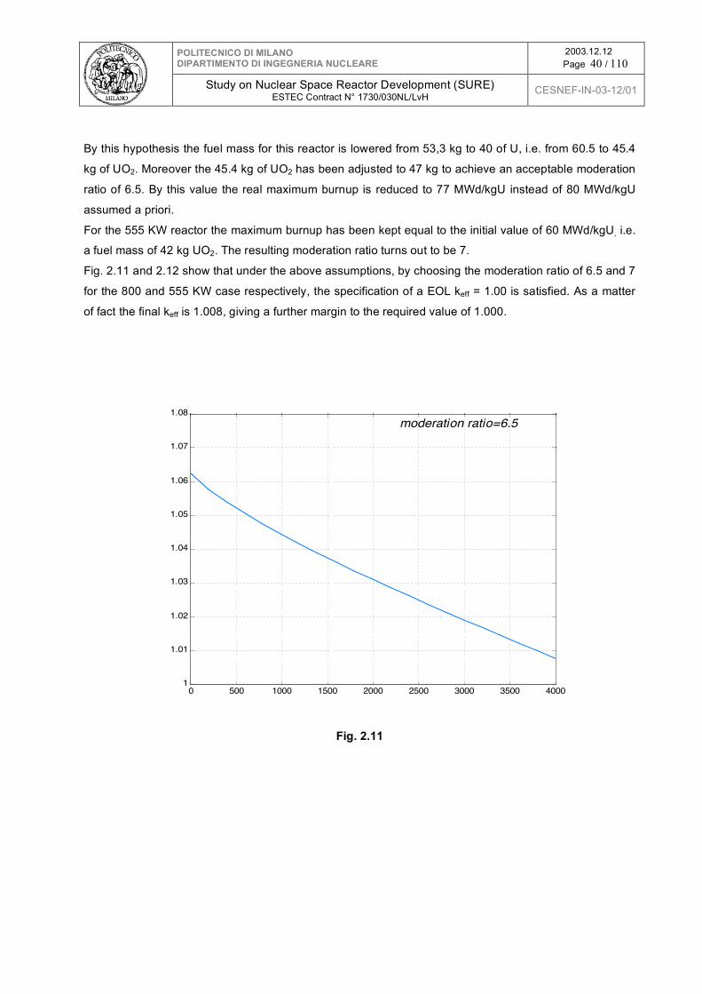
POLITECNICO DI MILANO DIPARTIMENTO DI INGEGNERIA NUCLEARE
2003.12.12 Page 40 / 110
Study on Nuclear Space Reactor Development (SURE)
ESTEC Contract N° 1730/030NL/LvH CESNEF-IN-03-12/01
By this hypothesis the fuel mass for this reactor is lowered from 53,3 kg to 40 of U, i.e. from 60.5 to 45.4
kg of UO2. Moreover the 45.4 kg of UO2 has been adjusted to 47 kg to achieve an acceptable moderation
ratio of 6.5. By this value the real maximum burnup is reduced to 77 MWd/kgU instead of 80 MWd/kgU
assumed a priori.
For the 555 KW reactor the maximum burnup has been kept equal to the initial value of 60 MWd/kgU, i.e.
a fuel mass of 42 kg UO2. The resulting moderation ratio turns out to be 7.
Fig. 2.11 and 2.12 show that under the above assumptions, by choosing the moderation ratio of 6.5 and 7
for the 800 and 555 KW case respectively, the specification of a EOL keff = 1.00 is satisfied. As a matter
of fact the final keff is 1.008, giving a further margin to the required value of 1.000.
0 500 1000 1500 2000 2500 3000 3500 40001
1.01
1.02
1.03
1.04
1.05
1.06
1.07
1.08
Effective full power days
K effective
moderation ratio=6.5
Fig. 2.11

POLITECNICO DI MILANO DIPARTIMENTO DI INGEGNERIA NUCLEARE
2003.12.12 Page 41 / 110
Study on Nuclear Space Reactor Development (SURE)
ESTEC Contract N° 1730/030NL/LvH CESNEF-IN-03-12/01
0 500 1000 1500 2000 2500 3000 3500 40001
1.01
1.02
1.03
1.04
1.05
1.06
Effective full power days
K effective
moderation ratio = 7
Fig. 2.12
Figures 2.13 and 2.14 show the final fuel channel disposition in the 800 KW and 555 KW case, respectively:
-40 -30 -20 -10 0 10 20 30 40
-40
-30
-20
-10
0
10
20
30
40
1 35
79
Fig 2.13

POLITECNICO DI MILANO DIPARTIMENTO DI INGEGNERIA NUCLEARE
2003.12.12 Page 42 / 110
Study on Nuclear Space Reactor Development (SURE)
ESTEC Contract N° 1730/030NL/LvH CESNEF-IN-03-12/01
-40 -30 -20 -10 0 10 20 30 40
-40
-30
-20
-10
0
10
20
30
40
1 3 57
9
Fig. 2.14
The resulting data are given in par. 2.11. It is interesting to note that the core size is almost the same for
the two required powers: the equivalent diameter is 36,8 cm for 800 KW and 36.3 cm for 555 KW core.
Thus the overall mass (core+reflector) of the 555 KW case is only slightly lower: 234 against 247 kg.
2.3 Electrical power generation system
To transform the reactor thermal power to electrical power a thermodynamic generation system is
needed. In PWR case, we discarded the possibility to use a thermoelectric device, because the relatively
small temperature difference between hot and cold wells, would yield a too low efficiency, of the order of
2-3 % (see for more details par. 3.4).
Therefore, two conventional thermodynamic cycles have been considered:
♦ A Rankine cycle with steam;
♦ A Rankine cycle utilizing an organic fluid.
Before starting the efficiency calculations, a preliminary optimization study has been carried out
concerning the cold well temperature. This optimization is based on the minimum mass of the overall
system including the reactor, the cold well, and a contingency of 20 %. In both cycles, the result has been
that the optimum is in the 160-180 °C range, with a rather flat behavior. Then a value of 165 °C has been
chosen at this stage of the work. The maximum temperature can be obtained by a detailed design and

POLITECNICO DI MILANO DIPARTIMENTO DI INGEGNERIA NUCLEARE
2003.12.12 Page 43 / 110
Study on Nuclear Space Reactor Development (SURE)
ESTEC Contract N° 1730/030NL/LvH CESNEF-IN-03-12/01
optimization of the steam generator (see later on). A preliminary study to this procedure has yielded a
value for this temperature approximately equal to the minimum primary temperature of 335 °C.
2.3.1 The Rankine steam cycle
This well known and widely adopted cycle has been calculated by imposing specific requirements tending
to simplify as much as possible the system and by assuming reasonably low turbine efficiency to take into
account its small size, which is outside the present technology. In particular, in spite of the fact that with
the relatively low steam temperature a saturated steam cycle would be convenient from the efficiency
stand point, this solution has been discarded to reduce as much as possible the moisture along the cycle
and at the condenser inlet and to avoid in any case the need of a moisture separator. A high moisture
value is in general viewed as a danger for its effects on turbine blade erosion, which would become
unacceptable for 4000 days of operation without maintenance. Then we adopted the following
hypotheses and data:
♦ Inlet steam temperature: 335 °C;
♦ Condensing temperature 165 °C;
♦ No regeneration along the turbine expansion;
♦ No re-superheating in the middle of turbine expansion;
♦ No moisture separator along the expansion;
♦ Maximum discharge moisture 3 %;
♦ Turbine efficiency: 73 %;
♦ Feed pump efficiency: 75 %;
By adopting these data an efficiency equal to 13.1 % has been obtained, in correspondence of a boiling
pressure of 5.7 MPa and an inlet superheating of 63 °C. This is a gross efficiency, which takes into
account only the power absorbed by the feed pump. Assuming that the system will grossly need a power
of 5 KW for the primary pump, the cold well cooling system (to be detailed), and the ancillary circuits, the
net efficiency is obtained by multiplying the gross efficiency by the ratio 100/105, and then the resulting
value is equal to 12,5 % .
In conclusion, in order to produce 100 KWe of net power, the reactor thermal power is set equal to 800
KWth.
2.3.2 Organic fluid Rankine cycle
The cycle efficiency is of paramount importance in order to minimize sizes and masses of the overall
system. By using a conventional steam Rankine generator system the above efficiency results rather low.
It is well known that in relatively low temperatures and low temperature differences between hot and cold
wells, an organic fluid (CxHy) would give higher values. This advantage is counterbalanced by some
drawbacks as the presence in the system of a different fluid, which requires an ad hoc supply system and

POLITECNICO DI MILANO DIPARTIMENTO DI INGEGNERIA NUCLEARE
2003.12.12 Page 44 / 110
Study on Nuclear Space Reactor Development (SURE)
ESTEC Contract N° 1730/030NL/LvH CESNEF-IN-03-12/01
ad hoc reservoir to cope with possible leakage in the long run, and the possibility to have an insufficient
thermal stability of the compound for the 4000 days period. These issues will be addressed in a
prosecution of the program, here we limit our analysis to a rough estimate of the efficiency to focus the
possible advantages of such an alternate generator.
The efficiency has not been calculated directly, because the variety of fluids and their complex
thermodynamic properties behavior would render such an approach too challenging in this stage of the
work. The approach has been to extrapolate a published datum to our conditions.
By referring for instance to the scheme represented in Fig. 2.15, the authors of the paper in rif. 8
calculated the efficiency of a cycle using the organic compound tetrametilbenzene (C10H14), working
between 300 and 60 °C and with a turbine efficiency of 75 %. The resulting efficiency is equal to 28 %.
The rather usual way to extrapolate the Rankine efficiencies to other conditions is that to adopt the same
ratio with the Carnot efficiency. In this case the Carnot efficiency would be 41.9 %, then the ratio actual
efficiency over Carnot efficiency is 67 %.
Fig. 2.15
In our condition the organic inlet temperature is 335 °C and the discharge temperature 165 °C2. The
corresponding Carnot efficiency is 28 %, which multiplied by 67 % gives the cycle efficiency of 18,76 %.
To complete the preliminary study of an organic fluid application, this value has been assumed for
defining the whole system.
This is the gross efficiency, which, taking into account a power absorption of 5 KW, as above done for
steam cycle, is reduced to 17,9 %, finally rounded to 18 %.
By adopting this value the reactor thermal power is set equal to 555 KW.
2 This extrapolation procedure might be a little conservative, being the temperature interval lower than the reference one.
R

POLITECNICO DI MILANO DIPARTIMENTO DI INGEGNERIA NUCLEARE
2003.12.12 Page 45 / 110
Study on Nuclear Space Reactor Development (SURE)
ESTEC Contract N° 1730/030NL/LvH CESNEF-IN-03-12/01
2.4 The primary system
The primary system is made by the reactor vessel which contains the reactor core, the barrel, the steam
generator, the pressurizer, the circulating pump, the safety valve, the reactivity control mechanism and
the instrumentation. All these components are inside the reactor vessel, thus adopting the so called
integrated solution. This allows to keep the size and the mass of the primary system to a minimum,
together with the elimination of the possibility to have any break of the pipes, which is the main cause of
having Loss Of Coolant Accidents (LOCAs); moreover the fast neutrons fluence on the vessel is reduced.
Therefore, the only pipes connected to the vessel are the ones of the steam and the liquid of the
secondary generator system; note that these pipes are connected to a closed circuit inside the vessel,
and thus no connection with the primary system is possible.
Water flows upward through the core and then through the lower part of the upper plenum (the remaining
part is filled with steam for the pressurizer), where the flow direction is reversed and the coolant is
directed downward through the annular downcomer region, between the core barrel and the vessel; in
this annular space the steam generator is located; the primary water flows on the outer surface of the
steam generator tube, exchanging heat with the secondary fluid (water or organic compound) till the lower
plenum, where the suction of the circulating pump is located; finally the pumped coolant enters the
reactor core to close the circuit (see Fig. 2.22-23 for the layout of the primary system).
The design pressure of the primary system is equal to the operating pressure multiplied a factor of 1.10,
which takes into account the value of the safety valve setting. This component is absolutely needed for
each pressurized system, but in our case implies an important issue concerning the consequences of its
operation in the case of pressure transients above 1.10 operating pressure, which means a discharge of
a substantial fraction of the primary water. For the time being we adopted a higher value than the usual
one in order to reduce the possibility of its intervention (1.10 against 1.07). The design pressure has been
then set to 15.5x1.10 = 17.05 MPa.
2.4.1 The reactor vessel
Three possible geometry were considered for this component: sphere, cylinder with hemispheric domes,
cylinder with semi ellipsoidal domes. A parametric study of the masses and volumes of the three
alternatives, which are to satisfy the space requirements of a cylindrical core, arrived at the conclusion
that all were almost equivalent, with a slight preference for the cylinder with hemispheric domes. The
latter is also preferable for accommodating the steam generator in the annular space between the barrel
and the vessel. Moreover, the spherical domes are better suited than ellipsoidal ones for accommodating
the pressurizer in the upper dome and the pumps in the lower one (see below). Then the final choice is
the cylinder with hemispheric domes.
The vessel size has been determined by adopting the scheme of Fig 2.14 and 2.15. The final choice has
been to use the following data: a = 120 mm (equal to the reflector thickness), b = 33 mm (to

POLITECNICO DI MILANO DIPARTIMENTO DI INGEGNERIA NUCLEARE
2003.12.12 Page 46 / 110
Study on Nuclear Space Reactor Development (SURE)
ESTEC Contract N° 1730/030NL/LvH CESNEF-IN-03-12/01
accommodate the steam generator), c = 120 mm (to better protect the vessel from the escaping radiation
in the corner points). The value of b is important for controlling the neutron fluence and the radiation
shielding capability inside the vessel: both issues are to be addressed in a prosecution of the work. Here
it can be stressed that any increment of this value would be rather penalizing for the overall mass.
a
b core
core barrel
reactor vessel
Fig. 2.16
D a b
c
X
I
45o
Fig. 2.17
The vessel material is steel; this is a conservative choice, anyway motivated by the fact that the only
possible alternate material is Titanium. This material has a density of 4500 kg/m3, which is rather lower
than that of steel (7800 kg/m3), however its features both in terms of strength and corrosion resistance
are to be established, taking into account that a variety of alloys exists, having different behavior (the best

POLITECNICO DI MILANO DIPARTIMENTO DI INGEGNERIA NUCLEARE
2003.12.12 Page 47 / 110
Study on Nuclear Space Reactor Development (SURE)
ESTEC Contract N° 1730/030NL/LvH CESNEF-IN-03-12/01
experience is in Russia). Moreover, Titanium is not much resistant to creep, as shown by the maximum
operating temperature established by ASME code equal to 315 °C (600 °F), which is 30 °C lower the
outlet core temperature; fabrication processes are more difficult, especially the welding. The first guesses
show that only moderate advantages are possible by using this material, thus a more detailed analysis
and the corresponding final decision have been delayed to a next activity.
Steel recently adopted for PWR vessels has an allowable stress of 205 MPa. As a matter of fact the
conventional vessels are made by carbon steel plated on the inside surface by stainless steel. The above
allowable stress refers to carbon steel. In our case, it may be probable that the whole vessel will be made
only by stainless steel, taking into account the small value of the thickness, when compared to that of
conventional vessels. In this case the allowable stress must be referred to the particular stainless steel
adopted. For the time being the above value has been adopted yielding a thickness for the two reactors
equal to 29.3/29.1 mm and 14.65/14.55 mm respectively for the cylindrical portion and the spherical
domes.
The barrel has the function to separate the reactor core zone from the annular peripheral one where the
out of core coolant is circulated at the reactor inlet and at the same time cooled down by exchanging heat
to the steam generator, here located. The barrel is a simple steel cylinder not undergone to any particular
load. Thus its thickness is determined by the requirement to have a good rigidity and to reduce fast
fluence on the vessel if necessary: a value of 15 mm has been assumed.
The vessel plus barrel mass is equal to 641 kg and 624 kg for 800 and 555 KW respectively.
The overall reactor masses are 1112 kg for the 800 KW and 1078 kg for the 555 KW reactor, assuming
conservatively cold water completely filling the pressure vessel. All mass and volume data for the primary
integrated circuit are detailed in par. 2.11.
The sketches of the horizontal cross section are shown in Fig. 2.16 and 2.17 referring to the 800 and the
555 KW cores, respectively. The sketch of the vertical cross section is shown in Fig. 2.20 referring only to
the 800 KW core since, as said before in sec. 2.2.3, the core sizes are almost the same for both powers
and then also the pressure vessel.
Fig. 2.18

POLITECNICO DI MILANO DIPARTIMENTO DI INGEGNERIA NUCLEARE
2003.12.12 Page 48 / 110
Study on Nuclear Space Reactor Development (SURE)
ESTEC Contract N° 1730/030NL/LvH CESNEF-IN-03-12/01
Fig. 2.19
Fig. 2.20
2.4.2 The steam generator
Several configurations are possible for the steam generator (SG): straight tube, U-tube, C-tube, bayonet
tube, helical tube. Based on a thorough analysis carried out for an integrated PWR reactor (IRIS), a
helical coil tube bundle has been selected [9]. This is a proven design that has operated in various
reactors, including the French Superphenix. There is also the positive ten years operating experience of
the German ship Otto Hahn. This design is capable of accommodating thermal expansion without

POLITECNICO DI MILANO DIPARTIMENTO DI INGEGNERIA NUCLEARE
2003.12.12 Page 49 / 110
Study on Nuclear Space Reactor Development (SURE)
ESTEC Contract N° 1730/030NL/LvH CESNEF-IN-03-12/01
excessive mechanical stresses, has high resistance to flow induced vibrations, and is designed to have
thermal performance second only to a straight tube design, which is to be discarded for the high loads
created by temperature transients.
As far as the reliability of such a component is concerned, it is well recognized that current PWR steam
generators face various degradation mechanisms, which imply extended inspections, maintenance and
repairs. The latest annual report on SG performance published by EPRI [10], in the frame of the Steam
Generator Management Project (SGMP), details the major issues and degradation mechanisms
contained within SG degradation database: for instance, in 1999 for the 238 operating plants a total of
8546 tubes were repaired owing to different degradation mechanisms, mainly due to stress corrosion
cracking (SCC). In general, SGs show a shorter life than that of the overall plant, which makes their
troublesome periodic replacement a common practice.
Therefore, it would seem that SGs inside the pressure vessel be the cause of impairing substantially the
reliability of the plant as in the current ones. However, the steam generator design here proposed is so
different that the present degradation experience of current SGs is not directly applicable.
The main design difference is that all the sensible components inside the pressure vessel - i.e. tubes,
headers and nozzles crossing the pressure vessel wall - are compressed instead of being stretched,
because the higher primary pressure is acting on the outer surfaces: strictly speaking, primary stresses
are compressive. In the case of tubes, stability requirements to avoid their collapse imply the adoption of
a tube thickness that is about twice as much the value needed to resist to the pressure compressive
stress, based on full (primary) outer pressure. Considering that the secondary side pressure is 5.7 MPa,
in normal operation the thickness is about three times the value needed to resist to the compression
stress. This means that deterioration mechanisms due to high stresses, such as fatigue, should inherently
be eliminated; those ones connected to SCC on both surfaces are not possible from a mechanical point
of view, i.e. considering only the compressive primary stresses.
Magnetite and copper impurities, or other such as lead, on the inner surface in contact with the secondary
fluid can be an issue, which should be thorough addressed when choosing the materials of the turbine
system.
In this design, several orifices or ferrules are to be inserted in the inlet section of the tubes, in order to create
an additional pressure drop in the water zone both to stabilize the flow from the parallel channel instability
phenomenon and to promote an even flow distribution through the tubes in the tube bundle. This additional
pressure drop is not yet defined, but should be of the order of the overall pressure drop in the tube. This
aspect deserves a special attention both for constructive and functioning reasons; the latter one means that
some erosion-corrosion phenomenon may here originate.
Taking into account the limited power to be transferred in this case, it has been decided to adopt a single
tube in order to eliminate the above mentioned instability phenomena. This would imply to choose a
reasonable high value of the diameter and the length of the tube.
A rather detailed mechanical design of a tube subjected to external pressure of 17.05 MPa and zero
pressure inside yields a thickness value of 11 % of internal diameter, by using the material inconel TT690.

POLITECNICO DI MILANO DIPARTIMENTO DI INGEGNERIA NUCLEARE
2003.12.12 Page 50 / 110
Study on Nuclear Space Reactor Development (SURE)
ESTEC Contract N° 1730/030NL/LvH CESNEF-IN-03-12/01
In this case the chosen inner diameter is 20 mm, then the thickness is 2.2 mm and the outer diameter
24.4 mm. The well known RELAP5 [5] calculation program suitable for thermalhydraulic system analysis,
both in steady state and transient conditions has been used for sizing the SG. Some adaptations were
introduced in order to take into account the particular geometry of this SG. However, no benefit for the
helix geometry effect on the inside heat transfer coefficient and for the outside spacers on the outside
heat transfer coefficient are taken into account; that means that the overall size here detailed may be over
estimated. The results are shown in the Table 2.5. They seem well within the existing experience
especially as far as the length and the secondary pressure drops are concerned. However the
thermalhydraulic behavior of helix was not well studied in past, then a experimental campaign is needed
for its development, also to take into account the effect of lack or reduced gravity.
Tab. 2.5 : Steam Generator data
Power [KW] 800
Secondary fluid Water
Geometry
Helical single tube
around the barrel
Annular gap width [mm] 33
ID/OD/t [mm] 20/24.4/2.2
Tube length [m] 50
Coil diameter [m] ~ 0.68
Coils number 23
SG height [m] 0.80
SG weight [kg] 60
Primary fluid temperatures inlet-outlet [°C] 345-335
Secondary fluid temperatures inlet-outlet [°C] 165-335
Primary/secondary pressures [MPa] 15.5/5.7
Primary flowrate [kg/s] 10.1
Max. primary mass flux [kg/m2s] 549
Secondary flowrate [kg/s] 0.347
Secondary mass flux [kg/m2s] 1103
Primary SG pressure drops [KPa] 5
Secondary SG pressure drops [KPa] 500
For organic fluid there are three differences: i) the power to be transferred is 555 instead of 800 KW, ii)
the transport properties of complex organic fluids, as here assumed, are worse than the water ones, iii)
the organic cycle uses only saturated fluid, then inside the SG there is no superheated zone. Probably
these differences are self compensating, so that the overall SG surface may result almost equal to the

POLITECNICO DI MILANO DIPARTIMENTO DI INGEGNERIA NUCLEARE
2003.12.12 Page 51 / 110
Study on Nuclear Space Reactor Development (SURE)
ESTEC Contract N° 1730/030NL/LvH CESNEF-IN-03-12/01
water one. If this is the case, also the overall layout will be similar, being the core size practically equal.
These issues will be clarified when and if the organic fluid will be chosen for this application. This requires
a definite choice of the fluid and consequently of its physical properties.
2.4.3 The pressurizer
The pressurizer is a big issue in PWRs. It is made by a pressure vessel where saturated water and
saturated steam are in equilibrium exactly at the operating pressure. The water zone is connected by a
relatively small pipe to the primary circuit. Since the maximum water temperature at the reactor outlet is
well below the saturation pressure (about 15 °C), the pressurizer water is to be heated by special
electrical heaters. The pressure is controlled by acting on the electrical power of the heaters and by
spraying a small flow rate of colder water into the steam zone. It is a rather complex system, which can
be simplified by putting the pressurizer in direct connection to the vessel (in the upper dome in our case)
and bringing the outlet temperature to the saturation value, as here done. The sprayed water may be
eliminated if a big steam volume is chosen and a certain pressure oscillation of moderate entity is
permitted. On the contrary in a big PWR the pressure must be well within given limits to reduce the
mechanical stresses, which are particularly compelling in this case.
An abundant free steam volume, as 30 liters per MW, which is several times the value used in
conventional PWRs, is here adopted. That means in our case 24 and 17 liters for 800 and 555 KW
reactors respectively. The spray water is then eliminated. These volumes are only a fraction of the upper
sphere volume, which is equal to about 90 liters.
Besides this free volume we have to foresee the possibility to contain the water expansion between cold
and hot conditions; in fact the specific volume increases by a factor 1.64, going from ambient temperature
(on the earth) to the average reactor temperature of 340 °C. This means that there are two alternatives:
discharge the excess of water to an ad hoc vessel or to leave a void inside the cold vessel exactly equal
to the above volume difference.
The first solution seems to penalize the system in terms of mass and volume, because this excess of
water is to be discharged during the start up operation in an external reservoir; however, a given amount
of water is probably needed to cope with probable leakages during the long period of operation.
The second one imply some issues. Assuming for simplicity a vessel made by a cylinder with diameter D
equal to the height and spherical domes (see Fig 2.22), its volume is equal to 5/12(πD3). Disregarding
any solid component inside the vessel, this approximately represents the total volume of water; reducing
this volume by 1.64 times an initial height of cold water in the cylinder equal to 0.67 D is obtained. This
means that the initial level does not cover entirely the whole core. The acceptability of this condition
depends on the start up procedure, which in turns depends on some specific requirements, not well
defined at this stage of design. Maybe that an intermediate solution between the two ones is advisable.
Obviously the above pressurizer, integrated inside the vessel, is possible only in presence of a given
value of the gravity to separate steam and water. This is the case for surface reactor, but not for

POLITECNICO DI MILANO DIPARTIMENTO DI INGEGNERIA NUCLEARE
2003.12.12 Page 52 / 110
Study on Nuclear Space Reactor Development (SURE)
ESTEC Contract N° 1730/030NL/LvH CESNEF-IN-03-12/01
propulsion one. Some pressurization alternatives can be imagined, but each of them is to be carefully
studied and experienced. We leave it for a future activity.
2.4.4 The circulating pump
In the introduction it has already been said that the natural circulation of the primary water has been
excluded, thus a circulating pump is needed. The chosen pump is the spool type, [3] which has been
used in marine applications and designed for chemical plant applications requiring high flow rates and low
developed head. The motor and pump consist of two concentric cylinders, where the outer ring is the
stationary stator and the inner ring is the rotor, that carries high specific speed pump impellers.
A sketch of the spool pump is shown in Fig. 2.21.
Fig. 2.21
The spool pump is located entirely within the reactor vessel; only small penetrations for the electrical
cables are required. High temperature windings and bearing materials are being developed in a US
industry to eliminate the need of cooling water and the associated piping penetrations trough the reactor
vessel. Moreover, the demonstration of long lasting operating capability, without any maintenance and

POLITECNICO DI MILANO DIPARTIMENTO DI INGEGNERIA NUCLEARE
2003.12.12 Page 53 / 110
Study on Nuclear Space Reactor Development (SURE)
ESTEC Contract N° 1730/030NL/LvH CESNEF-IN-03-12/01
inspection activity, is part of this development program. The achievement of these goals is prejudicial for
this application, because simplicity and reliability is a must for all components.
In addition to the advantages derived from its integral location, the spool pump geometric configuration
provides high inertia/coast-down and high run-out flow capability, that contributes to mitigating the
consequences of loss-of-flow accidents (LOFAs).
Because of their low developed head, spool pumps have not previously been considered for nuclear
applications. This integral core configuration and low coolant path pressure drop, however are an ideal
match for these pumps and can take full advantage of their unique characteristics. For this application,
the pump is much smaller than those under development and in principle this seems to be an advantage,
however a verification should be done.
The main preliminary characteristics of the spool pumps are detailed in the Table 2.6. By using these
data, the pump features amply remain in the range of axial pump zone.
Tab. 2.6 : Spool pumps characteristics
Reactor thermal power (KW) 555 800
Fluid Water Water
Operating pressure [MPa] 15.5 15.5
Assumed head [KPa] 20 20
Operating temperature [°C] 335 335
Mass flow [kg/s] 7.0 10.1
Volumetric flow [liters/s] 11.1 16.1
Efficiency 0.6 0.6
Power [W] 370 540
The remaining components are the safety valve, the control mechanism and the instrumentation. The
safety valve does not require particular consideration apart from the issue mentioned above about the
effects of its operation. The control mechanism will be addressed in the next paragraph. The
instrumentation can be considered rather conventional, but how to treat the relative information is an
open issue, which should be considered in the following.
The overall resulting structure of the primary system is depicted in Figs. 2.22 and 2.23.

POLITECNICO DI MILANO DIPARTIMENTO DI INGEGNERIA NUCLEARE
2003.12.12 Page 54 / 110
Study on Nuclear Space Reactor Development (SURE)
ESTEC Contract N° 1730/030NL/LvH CESNEF-IN-03-12/01
Fig. 2.22
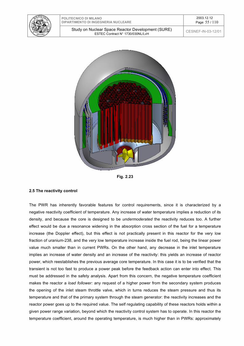
POLITECNICO DI MILANO DIPARTIMENTO DI INGEGNERIA NUCLEARE
2003.12.12 Page 55 / 110
Study on Nuclear Space Reactor Development (SURE)
ESTEC Contract N° 1730/030NL/LvH CESNEF-IN-03-12/01
Fig. 2.23
2.5 The reactivity control
The PWR has inherently favorable features for control requirements, since it is characterized by a
negative reactivity coefficient of temperature. Any increase of water temperature implies a reduction of its
density, and because the core is designed to be undermoderated the reactivity reduces too. A further
effect would be due a resonance widening in the absorption cross section of the fuel for a temperature
increase (the Doppler effect), but this effect is not practically present in this reactor for the very low
fraction of uranium-238, and the very low temperature increase inside the fuel rod, being the linear power
value much smaller than in current PWRs. On the other hand, any decrease in the inlet temperature
implies an increase of water density and an increase of the reactivity: this yields an increase of reactor
power, which reestablishes the previous average core temperature. In this case it is to be verified that the
transient is not too fast to produce a power peak before the feedback action can enter into effect. This
must be addressed in the safety analysis. Apart from this concern, the negative temperature coefficient
makes the reactor a load follower: any request of a higher power from the secondary system produces
the opening of the inlet steam throttle valve, which in turns reduces the steam pressure and thus its
temperature and that of the primary system through the steam generator: the reactivity increases and the
reactor power goes up to the required value. The self regulating capability of these reactors holds within a
given power range variation, beyond which the reactivity control system has to operate. In this reactor the
temperature coefficient, around the operating temperature, is much higher than in PWRs: approximately

POLITECNICO DI MILANO DIPARTIMENTO DI INGEGNERIA NUCLEARE
2003.12.12 Page 56 / 110
Study on Nuclear Space Reactor Development (SURE)
ESTEC Contract N° 1730/030NL/LvH CESNEF-IN-03-12/01
equal to -300 against -30 pcm/°C, and this would improve appreciably the self regulating capability of the
reactor. This is important for safety aspects, however, this feature should not be exploited currently for the
control, because the reactor should operate at constant power.
On the other hand the reactivity excursions in these reactors are rather important. In a typical PWR the
total reactivity difference between a cold condition with the fuel at the Beginning Of Life (BOL) and the hot
reactor at full power with the fuel at the End Of Life (EOL) is approximately equal to 24000 pcm (10-5). A
logical subdivision of this reactivity variation is as follows (in brackets the typical values for PWRs in pcm,
10-5 ):
1. Reactivity decrease going from cold condition to operating temperature (6000);
2. Reactivity decrease from zero power to full power conditions (this term includes the absorptions by
Xe and Sm, which reach their equilibrium value in tenths hours) (4000 = 1200 for Doppler + 2800
for Xe and Sm);
3. Reactivity decrease along the fuel life to cope with reduction of fissile material and accumulation of
poisoning fission products (14000);
4. Reactivity margin to control the reactor power (500).
The control of this big amount of reactivity is done by the combined use of several systems:
a. A neutron poison (Boric acid) diluted into the coolant, the concentration of which is varied
according to the needs. However, its maximum concentration and then the maximum reactivity
absorption is limited by the condition that the temperature reactivity coefficient remain negative; in
fact the water expansion due to a temperature increase makes decrease the poison concentration
as well and above a given concentration this effect in terms of reactivity is such to counterbalance
the negative temperature effect of pure moderator. The system which controls the poison
concentration during the reactor operation is rather complex and its action is obviously rather slow.
b. The use of a neutron absorbers spread on the fuel surface (ZrB2) or dispersed inside the fuel,
gadolinium or erbium, which capturing a neutron transmute themselves in low absorbers elements.
Thus their effect on reactivity is maximum at BOL and reduces along the fuel life. The requirement
is that their effect be negligible at EOL, condition not satisfied by all alternatives, and to not
increase the initial flux peaks along the fuel life. However, in general the reactivity reduction does
not compensate exactly the one of fuel consumption and accumulation of fission products and thus
the other systems have to operate.
c. Control rods: mechanical devices made by high neutron absorbers which are moved inside or
outside the core, to vary the poisons content of the core. This system is very fast and is used also
to shut down rapidly the power (SCRAM). Each rod is moved singly, with small movements. This
system is mechanically complex, expensive and above all requires important penetrations in the
vessel, because the mechanisms controlling the movement are located outside the vessel on its
spherical dome.

POLITECNICO DI MILANO DIPARTIMENTO DI INGEGNERIA NUCLEARE
2003.12.12 Page 57 / 110
Study on Nuclear Space Reactor Development (SURE)
ESTEC Contract N° 1730/030NL/LvH CESNEF-IN-03-12/01
These systems are well developed and positively experienced in hundredths of PWRs, however they
cannot be straightforward used in this reactor. The present requirements are: simplicity and no or few
vessel penetrations. This can be partially facilitated by the fact that this reactor is to be brought at full
power and then remain there for the whole period of operation.
The overall reactivity excursions and the value of each single term is detailed in Table 2.7 (in brackets
typical PWR data):
Tab. 2.7 : Reactivity terms in pcm.
Power (KW) 555 800 Term 1 (6000) 23000 23000 Term 2 (4000) 500 500 Term 3 (14000) 4300 5500 Term 4 (500) ~ 0+ ~ 0+
Total (24500) 27800 29000
The differences between PWR and this reactor are due to the high enrichment and to a reduced extent
for the low power density. In particular, Term 2 is relatively small because of the low temperature increase
inside the rod and the low thermal flux: both the Doppler effect and the absorptions by Xe and Sm are of
modest impact.
The total reactivity is higher than that of PWR, because the much higher value of the term 1 is only
partially counterbalanced by the lower values of terms 2,3, and 4.
The first system, using variable boric acid concentration in the coolant requires a complex control circuit
outside the reactor, which is not advisable to implement in this reactor.
The second one might be used. However, in high enriched cores the poison concentration must be very
high, but the very low thermal fluxes typical of these cores prevent to burn substantially the poisons at
EOL, and this has been verified for ZrB2 , which cannot be used in these cores. Probably the best poisons
are those characterized by high absorption cross sections as in the case of gadolinium. However the
design of burnable poison solution is complex in any reactor, and then this activity has been postponed.
For the control rods there is not an easy answer: being high the reactivity to be controlled, several of them
are needed, necessarily moved in parallel by a single bar crossing the vessel and operated by an external
motor as used for each single rod in a PWR. In this solution the space into the vessel above the core
should be enough to accommodate the entire length of the rods when they are out of the core. For this
reason and other ones, many designs foresee the use of rods inside the reflector instead of in the
moderator. In this reactor the leakage of neutrons is so high, that a reflector poisoning may be enough to
reduce the reactivity. This has to be thorough verified. If this is the case, the control rods can be
imagined not going up and down into the reflector, but made by a rotating cylinder, having on its diameter
the poison plate. The rotation varies the angle of the poison plate, and then its neutron absorption
capability.

POLITECNICO DI MILANO DIPARTIMENTO DI INGEGNERIA NUCLEARE
2003.12.12 Page 58 / 110
Study on Nuclear Space Reactor Development (SURE)
ESTEC Contract N° 1730/030NL/LvH CESNEF-IN-03-12/01
Here a different proposal is put forward, based on the fact that the core is very small and its portions can
be probably moved apart rather easily. By this proposal we do not intend to discard the previous one,
which will be considered in detail during the prosecution of the work.
The principle is shown in Fig. 2.24 and 2.25.
Fig. 2.24
Fig. 2.25

POLITECNICO DI MILANO DIPARTIMENTO DI INGEGNERIA NUCLEARE
2003.12.12 Page 59 / 110
Study on Nuclear Space Reactor Development (SURE)
ESTEC Contract N° 1730/030NL/LvH CESNEF-IN-03-12/01
The core is divided in six moving slices each one having grossly a mass of 20 kg, operated by a single
mechanism (to be defined), The specification is that by moving apart the slices in outside direction up to a
maximum equal to the thickness of the reflector, the reactivity decreases slowly to a minimum equal to
that required for the overall control. The issues are the reactivity behavior versus distance and the overall
controlled value. For the latter, in the case it were not enough, the number of slices can be augmented
and/or the barrel against which the slices are pushed at the end of their movement can be poisoned3. The
first one is more delicate, because in the first part of the slices movement the reactivity tends to increase
slightly, because the reactor is undermoderated and by this movement the moderator is increased.
The neutronic calculation in such an articulated structure is rather complex4. Then it has been
approached gradually. A first approximation has been obtained by using the geometry qualitatively
depicted in Fig. 2.26, which represents two homogeneous axially infinite slabs, each one 4.5 cm thick and
surrounded by 10 cm reflector which can be split on both sides.
a) b)
Fig. 2.26
First the slabs are joined together as shown in Fig. 2.26 a. The slabs are formed only by uranium oxide
93 % enriched and hot water (340 °C) and their ratio has been varied till obtaining approximately the
same initial keff of the 800 KW core equal to about 1.085 . The calculations have been done by WIMS
program. When the slabs are progressively taken away, as shown Fig. 2.26 b, the keff follows the curve
detailed in Fig. 2.27.
3 The neutronic calculations done without simulating the barrel implicitly assume that all the escaping neutrons outside the reflector are lost and thus this is equivalent to have a poisoned barrel. 4 These calculations were done in parallel with those concerning the final choice of the reactor configuration. Therefore, the input data here adopted are not completely coherent with those detailed in par.2.2.3. In our opinion the results here given should not be not appreciably affected by this discrepancy. 5 Uranium-235 = 5.1 10 –4, Uranium-238 = 3.79 10-5, Oxygen = 2.67 10-2, Hydrogen = 5.35 10 –2, Boron = 7.5 10-6 in atoms/barn cm.

POLITECNICO DI MILANO DIPARTIMENTO DI INGEGNERIA NUCLEARE
2003.12.12 Page 60 / 110
Study on Nuclear Space Reactor Development (SURE)
ESTEC Contract N° 1730/030NL/LvH CESNEF-IN-03-12/01
The reactivity first rises, because the initial slab is under moderated, then reaches a maximum and
afterwards goes down rapidly: at 10 cm of slab distance keff is close to 1.01, not far from the final reactivity
of the same 800 KW core.
0 2 4 6 8 10 12 140.85
0.9
0.95
1
1.05
1.1
1.15
1.2
relative distance between slabs
k
-
e
f
f
e
c
t
i
v
e
Fig. 2.27
These first results seem encouraging, then more detailed Monte Carlo calculations have been performed
(see input data in Tab.2.4, but doing an interpolation for a moderation ratio = 6.5). The core has been
divided in six slices as shown in the previous Fig. 2.24 and 2.25 and then starting from the compact
configuration, they are taken away by three discrete steps 2.17, 8.70 and 10.86 cm respectively. The first
two steps have been calculated with an equivalent reflector thickness of 11.2 cm instead of 12 cm (the
present value for the reactor), The results are shown in the following Table:
Tab. 2.8 : keff for different radial displacement values
Radial slice displac. (cm) keff – hot keff – cold
0 1.09964 1.33186 2.17 1.12742 1.34292 8.70 0.95844 1.06874 10.86 0.85388 0.98500
These results confirm the above conclusions and in particular:
♦ The first keff rise and then the sharp decrease;
♦ A bigger decrease in cold conditions than in hot ones (24600 against 34700 pcm);
In conclusion one can imagine a sequence as follows:
♦ The reactor starts in cold conditions at the maximum outside displacement, where the reactivity
reaches the minimum below criticality; the slices are gently approached one other until Keff =1 is
obtained; the reactor starts producing power;
♦ As soon as the temperature rises, the slices are further approached one another in order to keep
constant at keff = 1;

POLITECNICO DI MILANO DIPARTIMENTO DI INGEGNERIA NUCLEARE
2003.12.12 Page 61 / 110
Study on Nuclear Space Reactor Development (SURE)
ESTEC Contract N° 1730/030NL/LvH CESNEF-IN-03-12/01
♦ As soon as the temperature reaches the operating one, the full power is produced and the fuel starts
burning;
♦ To compensate the reactivity reduction due to fuel burning, the slices are progressively approached
one another till the point of maximum reactivity, which may not be the above one, because this is to
be calculated with poisoned fuel;
In any condition the temperature reactivity coefficient is negative, because the cold keff curve is always
higher than the hot one. Moreover, it has been verified that in correspondence of the maximum reactivity
in hot conditions (1.12742) the temperature coefficient is equal to -266 pcm/°C.
If this is confirmed by further analyses, it can be said that this control procedure can in principle be
adopted. The demanding issues is the design of the slice command mechanism and how to avoid that the
water trapped between the slices does not mix with the outlet coolant, to avoid the lowering of its
temperature below the saturation. If this is the chosen solution, the reflector should be necessarily water,
as here already chosen.
2.6 The cold well
The cold well is one of the most crucial component of any thermodynamic cycle for space application . In
a terrestrial power station adopting the Rankine cycle a typical specific surface of a condenser cooled by
water coming from a river or a sea is about 0.02 m2/KWth. For instance, a nuclear power station of 1000
MWe dissipates in the condenser about 2000 MWth and thus the overall condenser surface is 40`000 m2.
Referring to the solution adopting the steam Rankine cycle with a power of 800 KW and a net efficiency of
12.5 %, the thermal power to be dissipated in the condenser is 700 KW6. By applying the above
parameter, a surface of 14 m2 would be obtained. However, this value is impossible to realize, because
of the lack of any cooling agent and the only way to dissipate heat is radiation. The Mars atmosphere is
practically made only by carbon dioxide at a pressure of 500 Pa, 200 times less than the atmospheric
terrestrial pressure. Thus, this gas has very low heat transport capability, even if it cannot be discarded
for this cooling action. In this case the gas is to be circulated by a blower. Some studies in the literature
show that this solution is possible and perhaps more convenient than the pure radiation mechanism.
However, in the present study this possibility has not been considered, deeming that the system would be
more complex and its reliability reduced, because of the blower, working with a not well defined fluid.
In a preliminary optimization study the conclusion was reached that the optimum condenser temperature
for minimizing the overall mass is around 165 °C. We adopt the following relationship:
( )40
4TTSQ s !""""= #$%
6 Actually the cycle gross efficiency (13.1 %) is to be taken into account for the condenser power, which is equal to 695 KW. However, the 5 KW absorbed by the various auxiliary systems are in part transformed in heat, which in some way is to be dissipated in a similar manner as for the main steam. In conclusion, the above number of 700 KW seems a good approximation of the practical situation.

POLITECNICO DI MILANO DIPARTIMENTO DI INGEGNERIA NUCLEARE
2003.12.12 Page 62 / 110
Study on Nuclear Space Reactor Development (SURE)
ESTEC Contract N° 1730/030NL/LvH CESNEF-IN-03-12/01
where ! is the surface emissivity (0.9 as a reasonable value), S [m2] the ideal radiating surface (without
view factor reduction), 81067.5
!"=# [W/m2K4] Stefan-Boltzman constant, Ts [K] the tube outer
temperature, T0 [K] is assumed equal to 300 K (this value intends to simulate the back radiation coming
from the Mars surface and it is equivalent to 0.25 KW/m2 ), α is the view factor assumed equal to 0.6. In
fact, if the tubes are disposed to form a cylinder, inside which the power system is located, the view factor
would be lower than 1 and 0.6 is a tentative value: the view factor can be defined when the condenser
layout is established.
With the above data, a value of 1.14 m2/KW is obtained (57 times more than the above typical value).
A parametric study shows that the condenser geometry is made by a bundle of several tubes connected
in parallel, having the following features:
ID = paramter to be optimized (inner diameter);
t = 7 % of ID (tube thickness)
L = 80 m (length of each tube)
N = tube number: depends on ID
The internal pressure of 0.7 MPa is relatively low, and the above thickness of 7 % ID is well beyond the
value needed to satisfy the stress limit; then it has been fixed on the basis to assure sufficient tube
rigidity, to cope with a given corrosion and to resist to micrometeorites impact. The latter requirement
probably would impose a constant thickness instead of a constant percentage of ID; however, taking into
account the scarcity of knowledge on this issue, it seemed more reasonable the choice of a constant
percentage of ID, as usually done in terrestrial applications.
The material, working in this case at relatively low temperature, may be titanium, the density of which is
4500 against 7800 kg/m3 of steel.
In fig. 2.28 the resulting values of overall mass and pressure drops of the condenser are shown. The
overall mass takes into account a 30 % increase of the overall tube mass for spacers and headers. The
graph shows that a linear decrease of the overall mass can be obtained by reducing the inner diameter.
However, the condenser pressure drops are inversely proportional to the third power of ID: this means a
reduction of the cycle efficiency, because its backpressure increases accordingly. A simplified evaluation
indicates that in correspondence of 20 KPa of backpressure increase, the efficiency reduces by about 1
%. This efficiency reduction is reasonably acceptable and it is obtained with ID = 6 mm. Probably an
optimization study would suggest that even a further reduction in efficiency may be convenient, taking into
account the corresponding mass saving. However a smaller ID would imply a proportional decrease in
tube thickness, and probably a not acceptable reduction in tube strength against meteorites.

POLITECNICO DI MILANO DIPARTIMENTO DI INGEGNERIA NUCLEARE
2003.12.12 Page 63 / 110
Study on Nuclear Space Reactor Development (SURE)
ESTEC Contract N° 1730/030NL/LvH CESNEF-IN-03-12/01
Fig.2.28
Then the overall mass results 1840, the overall surface 796 m2 and 464 tubes (2.6 kg/KW or 2.3 kg/m2).
It has been verified that the temperature drop inside the tube between the wall and the fluid is few tenths
of degree, then negligible: the radiation temperature of 165 °C is practically identical to the condenser
temperature. The pressure drops inside the tubes are about 20 Kpa, with respect to the absolute pressure
of 700 KPa.
The 80 m long tubes are supposed to form 4 contiguous U, 10 m high, for a total of 3708 legs. Assuming
that the tube legs are welded together, an overall linear dimension of 3708x0.00684 = 25.4 m is obtained.
In conclusion, the condenser can be imagined to be a cylinder of 8 m diameter and 10 m height. The final
design would take into account the real pay load size of the launching rocket. In particular, if necessary
the condenser can be divided in several identical pieces to be assembled on the site.
In the case of organic Rankine cycle the power to be dissipated is 555-100 = 455 KW. Even if in this case
we do not know the thermodynamic properties of the organic fluid, we can imagine, on the basis of the
above results, that the radiation mechanism is the controlling one, so that the overall dimensions are
about proportional to the power to be dissipated. Thus, adopting the same tubes their number is
decreased to 464x(455/700) = 302. By the same hypotheses, the condenser would be a cylinder of 5.3 m
diameter and 10 m height, while the total mass is 1840x(455/700) = 1196 kg.
All the above data are listed in par. 2.11. Figs. 2.29 and 2.30 show a simplified scheme and the layout of
the plant for the 800 KW reactor, respectively.
Rankine condenser Tcond=165 °C; Ltube= 80 m; tube thickness= 7% ID
0
500
1000
1500
2000
2500
3000
3500
4000
4500
5000
0 2 4 6 8 10 12 14 16
Tube inside diameter[mm]
To
tal w
eig
ht
[kg
]
0
50
100
150
200
250
300
350
400
450
500
Pre
ssu
re L
osses [
KP
a]
weight Pressure Losses

POLITECNICO DI MILANO DIPARTIMENTO DI INGEGNERIA NUCLEARE
2003.12.12 Page 64 / 110
Study on Nuclear Space Reactor Development (SURE)
ESTEC Contract N° 1730/030NL/LvH CESNEF-IN-03-12/01
Fig. 2.29
Fig. 2.30
2.7 Masses
In the previous sections the masses of the core, primary system and cold well has been detailed for both
the 800 and the 555 KW cores. We have not considered some further components of the complete
system yet, as for example the steam turbine, the tubes, valves, auxiliary circuits, internals and so on.
Concerning the small steam turbine, it is worth noting that this issue certainly requires an R. & D. program
in order to build steam turbine of about 100 KW with very compact size and high efficiency at the same

POLITECNICO DI MILANO DIPARTIMENTO DI INGEGNERIA NUCLEARE
2003.12.12 Page 65 / 110
Study on Nuclear Space Reactor Development (SURE)
ESTEC Contract N° 1730/030NL/LvH CESNEF-IN-03-12/01
time. We estimate for the moment a value of 2 kg/KWe for the mass per unit electrical power, resulting in
a mass of 200 kg for this component. The mass of the other not considered parts is globally assumed to
be about 200 kg for both reactors. Actually, in 555 KW the pressure of the secondary circuit is lower but
there is as an extra component, the regenerator.
At the end the mass of any single component has been increased of a margin of 5 % to take into acount
any kind uncertainty or disregarded parts. The final sum has then been increased by a further 10 % as a
contingency. The detailed values are shown in Tab 2.9.
The resulting overall masses are 3941 and 3158 kg for 800 and 55 KW respectively. This is equivalent to
a specific mass, which ranges between 40 and 32 kg/KWe, which seems a reasonable interval, being in
agreement with other proposals in the literature.
Tab. 2.9 : Masses in kg of PWR
800 KW 555 KW
Fuel (UO2 only) 47 + 42 +
Cladding 15 + 14 +
Shroud 16 + 15 +
Moderator (cold) 30 + 29 +
Reflector (cold) 139 134
Core+reflector = 247 + = 234 +
Barrel 138 + 135 +
Vessel 502 + 489 +
Downcomer water (cold) 42 + 41 +
Dome water (cold) 183 179
Overall reactor = 1112 + 5 % 1168 = 1078 + 5 % 1132
Cold well 1840 + 5 % 1932 1196 + 5 % 1256
Steam Generator 60 + 5 % 63 60 + 5 % 63
Turbine 200 + 5 % 210 200 + 5 % 210
Other components 200 + 5 % 210 200 + 5 % 210
Overall system 3583 2871
Contingency = 10 % 358 287
Total Mass of the System 3941 3158

POLITECNICO DI MILANO DIPARTIMENTO DI INGEGNERIA NUCLEARE
2003.12.12 Page 66 / 110
Study on Nuclear Space Reactor Development (SURE)
ESTEC Contract N° 1730/030NL/LvH CESNEF-IN-03-12/01
2.8 Preliminary safety considerations
A detailed safety analysis is outside the scope of this feasibility study, for its complexity and need to
define the detailed requirements. In fact this reactor from one side is nor subjected to the licensing
procedure of terrestrial reactors imposed by the safety authorities, from the other it must satisfy specific
safety issues connected to its launch and the possibility to fall down to the earth.
In the foreword it is mentioned that this nuclear system must satisfy the usual safety requirements of
terrestrial reactors and this is to be defined in detail, taking into account the above consideration about
the lack of a licensing procedure. Besides this the system has to assure that:
- no irradiated fuel is present at launch;
- the core subcriticality in the case of possible launch accidents (flooding);
- the radiation protection without impairing mass requirements;
- an easy decommissioning in space;
The first item is inherently satisfied, because the reactor would not reach its first criticality before being
outside terrestrial space. The second one seems inherently satisfied because a water reactor cannot be
flooded.
The third is a an important issue, which can be addressed only after having defined some conditions,
especially for the propulsion solution. In fact, for surface reactor, the shield cannot be transported from
the earth and it is to be provided by a suitable system layout on the Mars surface (regoliths around,
underground siting, big distances). For propulsion reactor an intermediate solution is to be found by
balancing the addition of a small shield around the core with the reduction of the radiation danger by
locating the reactor far away from the sensible zone (a separate capsule for the reactor?) or by locate an
extra shield only on the reactor portion viewed by the sensible zone.
The fourth one is too indefinite at this stage of the design, that no specific consideration can be drawn.
In this study, a calculation has been done to verify whether in the case of severe accidents the fuel
melting is avoided. It is well known that fuel melting represents the most feared situation for terrestrial
reactor, and the nowadays attitude for new reactor designs is to avoid this in any foreseeable
circumstance. It is not an easy task, but in the present case, the very small size of the reactor may be of
big help. If this is the case, it is justified the choice to eliminate any protection system to cool down the
fuel in the case of a complete loss of coolant (LOCA).
The fuel melting is connected to the fact that in the case of LOCA the reactor is inherently shut down,
because the loss of moderator makes the reactivity go down to very low values, but the fuel goes on
producing some power, the so called decay heat. If the fuel is no longer cooled by the water, the fuel
heats up adiabatically till it reaches its melting point. However, as soon as the fuel temperature rises, the
thermal radiation process takes place, the importance of which increases rapidly with the temperature.
This radiation power is exchanged among the rods inside the core and from the outer rods ring toward
the vessel and then from the latter toward the outside environment. Besides the radiation, there is also

POLITECNICO DI MILANO DIPARTIMENTO DI INGEGNERIA NUCLEARE
2003.12.12 Page 67 / 110
Study on Nuclear Space Reactor Development (SURE)
ESTEC Contract N° 1730/030NL/LvH CESNEF-IN-03-12/01
the convection of steam or air, which flowing inside the hot core brings its heat to the vessel walls and
from them to the outside world.
It is really difficult to simulate this situation by a model. A rather simplified but sufficiently realistic one has
been prepared, limiting conservatively the study only to the radiation process.
The temperature distribution inside the core has been evaluated using a computer program, based on a
model in which the whole core is divided in unit cells, having the geometry indicated in Fig. 2.31 [4]. Each
cell is made by four rod segments, each one equal to one quarter of circumference and by four imaginary
surfaces. The cells are connected one another by means of common imaginary surfaces, which transform
the impinging heat flux in a isotropic flux for the next unit.
a
b
d
c
Fig. 2.31
The hypothesis are:
• The fuel rod are in a square open lattice and are axially infinite;
• The rod power is axially uniform;
• The surface rod temperature is uniform;
• The emissivity of all surfaces is the same;
• Emission and reflection are isotropic;
• The rod surface is gray, while the connecting surfaces between two cells are black;
• The calculation is done in steady state, i.e. the decay power is assumed constant with time.
Two differences between the core geometry assumed in the first hypothesis and the present one: the
lattice is now hexagonal, and the rods are assembled in 19 rods and inserted in hexagonal channels.
Both differences should not modify appreciably the result: for the first point what is important is the
moderator to fuel ratio more than the lattice shape; for the second difference the effect can be more
pronounced, but anyway these shroud surfaces should introduce a further thermal resistance among the
rods, but being its temperature relatively high their effect should be modest. However both these
differences will be analyzed in further detail in the future.

POLITECNICO DI MILANO DIPARTIMENTO DI INGEGNERIA NUCLEARE
2003.12.12 Page 68 / 110
Study on Nuclear Space Reactor Development (SURE)
ESTEC Contract N° 1730/030NL/LvH CESNEF-IN-03-12/01
Once fixed the rod pitch, the distance of the outer rod row from the cold well, the rod diameter, the
program calculates the shape factors, defined as the fraction of the radiation leaving a surface Ai in
whichever direction and intercepted by a surface Aj. These coefficients are then used to calculate the
shape factors modified ψij, which represent the absorbed energy per unit time (the intercepted energy
minus the reflected one) by surface Aj when a given heat flux is emitted from surface Ai. Thus, determined
the modified shape factors and the connection method among the cells, the system of the balance
equations is solved. Assigned the power of each rod and the temperature of the cold well, the
temperature profile along the core radius can be calculated. The equations number is equal to the rods
number along the core radius and the unknowns are the net energies per unit time which leave each rod.
The form of each equation is:
( )! """#"""=j ji
4
jj
4
iiii TATAq $%%&
where εi is the emissivity of surface Ai, σ is the Stefan-Boltzmann constant, equal to 5.67·10-8 W/m2 K4
and Ti is the absolute temperature of surface Ai. The first term in the second member represents the
emitted power from surface Ai, while the second term is the absorbed power by Ai coming from all
surfaces AJ.
The power per unit rod surface has been calculated as
corerod
d
s
HDrodnumber
PP
!!!=
"
where Pd is the decay power, supposed 1 % of the nominal thermal core power. The last one is the
thermal power of the reactor and this means that a flat radial and axial profile has been assumed.
The vessel wall temperature is set at 750 K, but its value is not critical. In fact in one typical case going
from 500 to 1000 K the central rod temperature changes by 80 K. The rod emissivity has been set at
0.75. The rod pitch is 6.9 (Vm/Vu = 17.2) and 5.6 mm (Vm/Vu = 10.8) for 555 and 833 KW respectively. The
833 KW power was used when these calculations were done, and then it was reduced a little bit
coherently with an increased value of the cycle efficiency.
Once fixed the above data the only controlling parameter is the reactor power. The results are detailed in
Fig. 2.32 for the two powers of 555 and 833 KW. It can be seen that the maximum temperature is far from
the melting point of stainless steel (1700 K) and even more from that of uranium oxide (3000 K). If instead
of the average power of each rod the maximum radial one equal to 1.5 times is used the resulting
temperature is increased of about 100 K. However, this analysis should be improved in the future to take
into account the shrouds, the radial and axial flux distribution and the effect of rod pitch.

POLITECNICO DI MILANO DIPARTIMENTO DI INGEGNERIA NUCLEARE
2003.12.12 Page 69 / 110
Study on Nuclear Space Reactor Development (SURE)
ESTEC Contract N° 1730/030NL/LvH CESNEF-IN-03-12/01
Fig. 2.32
2.9 Open issues and R&D needs
This feasibility study has allowed us to find the open issues to be solved for going on this route, which
needs a R&D program. Here below a list of them, which is inevitably incomplete, is detailed; the order is
not based on their importance. The issues written in bold letters are those interesting for terrestrial
reactors and those written in italic those interesting for generic terrestrial applications as well.
- Fuel fabrication process of small diameter pellets;
- Fuel irradiation behavior due to the new geometry;
- Fuel gap definition;
- Cladding material: stainless steel or zircalloy;
- Hexagonal shrouds: material, dimension stability, fabrication;
- Internals: mechanical design;
- Increase of operating pressure: fuel implications, primary circuit materials; - Saturation temperature at the reactor outlet: effect of small boiling inside the core;
- The cold well as condenser;
- Small steam turbines;
- Organic fluids: composition stability, thermal transport capabilities;
- Small organic fluid turbine;
- Fluid leakage: how much, how to cope with;
- Maintenance requirements of the whole system;
- Optimum reflector: technological aspects - Pumps: development of spool pumps, reliability for long periods;

POLITECNICO DI MILANO DIPARTIMENTO DI INGEGNERIA NUCLEARE
2003.12.12 Page 70 / 110
Study on Nuclear Space Reactor Development (SURE)
ESTEC Contract N° 1730/030NL/LvH CESNEF-IN-03-12/01
- Fluence effects on vessel in these particular conditions;
- Shielding;
- Safety valves: reliability, how to cope their intervention;
- Vessel material different from stainless steel;
- Steam Generator thermalhydraulic behavior in helical geometry also in presence of low or no
gravity;
- Corrosion deposits inside the SG tube;
- The pressurizer: self pressurization, different concepts for propulsion reactor as feed and
bleed, cold pressurizer, centrifugal action;
- Control of the system and of the reactor and its constructive implications.
Even if this list is incomplete, no item seems to be unsolvable. An R&D program of reasonable extent
may yield the needed answers, but what is important that the most demanding researches also are of
interest for the new generation Light Water Reactors. Thus a cost sharing action can be proposed and
duly programmed, according to the time schedule of the commercial exploitations of these terrestrial
reactors.
2.10 Concluding remarks
At the end of this very preliminary feasibility study about the use of PWR system for space reactors, it can
be concluded that no insoluble issues have been evidenced, which would prevent of going on along this
route in order to execute a more detailed design. Then it will be possible to draw a more justified
conclusion about the usefulness to follow this solution.
At the beginning of the study it was supposed that the solutions for propulsion and surface application
might be the same. However, this hypothesis holds only partially, because the lack of gravity and of a soil
render the propulsion solution rather different and more demanding than the surface one. In particular,
two aspects have been outlined for propulsion reactors: the lack of steam water separation in case of lack
of gravity (pressurizer, steam moisture separation), and the need of an autonomous radiation shield,
which in surface reactors can be provided by the existence of a soil. On the other side, it was anticipated
in the foreword that the use of space nuclear reactors should be approached gradually starting from the
easiest application, which is that for surface use: this study is a confirmation of the statement.
If it will be confirmed in prosecution of the work that no insoluble issues are present in this proposal, it can
be stated that a reasonable R&D effort and consequently a relatively limited development cost and time
interval are only needed in this case.
In the short range, future design activities should address the detailing of many aspects of the analysis
presented in this report and adding new ones. Among the first ones, concerning the core, the choices to
limit the fuel burnup, the use of stainless steel instead of zircaloy for cladding and shroud, the reflector
material should be reconsidered: in fact these conservative choices affect the reactor size, which is an
important item to define the overall mass. While for the rest of the system: cold well in forced convection,

POLITECNICO DI MILANO DIPARTIMENTO DI INGEGNERIA NUCLEARE
2003.12.12 Page 71 / 110
Study on Nuclear Space Reactor Development (SURE)
ESTEC Contract N° 1730/030NL/LvH CESNEF-IN-03-12/01
reactivity and plant control. The new activities are: radiation shielding, vessel fluence, safety aspects,
choice of vessel/barrel material, overall layout, containment, leakage control, ancillary circuits for start up,
coolant purification, radiolisis. and other exigencies. Moreover, at the end of this further activity a
preliminary R.& D. program should be detailed.

POLITECNICO DI MILANO DIPARTIMENTO DI INGEGNERIA NUCLEARE
2003.12.12 Page 72 / 110
Study on Nuclear Space Reactor Development (SURE)
ESTEC Contract N° 1730/030NL/LvH CESNEF-IN-03-12/01
2.11 PWR reactor list of data
PWR - 800 PWR - 555
Power
Thermal [KW] 800 555
Electric [KW]
Primary circuit
Fuel
Composition
Enrichment BOL
Enrichment EOL
Diameter [mm]
Cladding
Material
Fuel channel
Geometry
# of rod
Fuel rod diameter [mm]
Height [mm] 361,5 352,7
Moderation ratio 6,5 7
Fuel pitch [mm] 4,846 4,996
Shroud material
Shroud thickness [mm]
Shroud density [kg/m3]
# of fuel bundle 261 239
total # of fuel rod 4959 4541
Burnup [MWd/kg] (assumed) 77 60
Pressure [MPa] (assumed)
Temperatures
T max [°C] (assumed)
T min [°C] (assumed)
Secondary circuit
Cold well temperature [°C]
Thermodinamic cycle Rankine steam Rankine organic fluid
Efficiency [%] 12,5 18
345
335
2,2
Hexagonal
Stainless steel
0,2
Stainless steel
15,5
165
100
UO2
93%
Thickness [mm]
Equivalent density [kg/m3] 6800
0,3
7800
~ 82%
1,8
19

POLITECNICO DI MILANO DIPARTIMENTO DI INGEGNERIA NUCLEARE
2003.12.12 Page 73 / 110
Study on Nuclear Space Reactor Development (SURE)
ESTEC Contract N° 1730/030NL/LvH CESNEF-IN-03-12/01
Miscellaneous data
Fuel quantity (UO2) [kg] 47 42
Specific power [KW/kg] 17 13,2
Linear power [KW/m]
Reflector
Material
Thickness [mm]
Core designs
keff EOL (assumed)
Mass (core+reflector) [kg] 247 234
Electrical power generation
Working fluid water C10H14
Inlet steam temperature [°C]
Condensing temperature [°C]
Max discharge moisture (assumed) 3% N.A.
Turbine efficiency (assumed) 73% N.A.
Feed pump efficiency (assumed) 75% N.A.
Absorbed el. power [KW] (assumed)
Reactor vessel
Design pressure [MPa]
Geometry [mm]
a
b
c
Material
Thickness [mm]
Cylindrical portion 29,3 29,1
Spherical portion 14,7 14,5
Barrel
Geometry
Material
Thikness [mm]
Vessel mass [kg] 502 489
Barrel mass [kg] 138 135
Core+reflector mass [kg] 247 234
Water (cold) 225 220
Overall vessel mass filled with cold water [kg] 1112 1078
Steam generator
Geometry
Annular gap width [mm]
ID/OD/T [mm]
Tube length [m]
Tube material
Coil diameter [m]
Coils number
SG height [m]
Inconel TT 690
165
1,000
120
water
0,68
23
0,80
5
33
20 / 24,4 / 2,2
50
Helical single tube around the barrel
33
120
15
Cylinder
17,05
120
335
0,39
SA 508, TP.3, Cl.2
SA 508, TP.3, Cl.2

POLITECNICO DI MILANO DIPARTIMENTO DI INGEGNERIA NUCLEARE
2003.12.12 Page 74 / 110
Study on Nuclear Space Reactor Development (SURE)
ESTEC Contract N° 1730/030NL/LvH CESNEF-IN-03-12/01
SG mass [kg]
Primary fluid temp. [°C]
inlet
outlet
Secondary fluid temp. [°C]
inlet
outlet
Primary/Secondary pressures [MPa] 15,5 / 5,7 15.5 / N.A.
Primary flow rate [kg/s] 10,1 N.A.
Max primary mass flux [kg/m2s] 549 N.A.
Secondary flow rate [kg/s] 0,347 N.A.
Secondary mass flux [kg/m2s] 1103 N.A.
Primary SG pressure drops [KPa] 5 N.A.
Secondary SG pressure drops [KPa] 500 N.A.
Pressurizer
Type
Steam volume [liters] 24 17
Circulating pump
Type
Operating pressure [MPa]
Head [KPa] (assumed)
Operating temperature [°C]
Mass flow [kg/s] 10,1 7,0
Volumetric flow [liters/s] 16,1 11,1
Efficiency
Power [W] 540 370
Reactivity control
Term 1 [pcm]
Term 2 [pcm]
Term 3 [pcm] 5500 4300
Term 4 [pcm]
Total [pcm] 27800 29000
# of moving slices
slice mass [kg]
Cold well
Type
Tube geometry
Inner diameter [mm]
Outer diameter [mm]
Thickness [mm]
Length [m]
Tube number 464 302
Internal pressure [MPa] 0,7 N.A.
Temperature [°C]
Specific surface [m2/KW]
View factor
Surface area [m2] 796 302
Mass [kg] 1840 1196
Dimension (cylinder)
height [m]
diameter[m] 8 5,3
Spool pump
Integrated
165
335
345
1,1
0,6
10
6
6,84
80
165
6
~ 20
23000
500
~ 0+
15,5
20
335
0,6
335
60
0,42
Bundle of tubes

POLITECNICO DI MILANO DIPARTIMENTO DI INGEGNERIA NUCLEARE
2003.12.12 Page 75 / 110
Study on Nuclear Space Reactor Development (SURE)
ESTEC Contract N° 1730/030NL/LvH CESNEF-IN-03-12/01
Masses [kg] (+5%)
Overall vessel weight filled with cold water 1168 1132
Cold well 1932 1256
Steam generator
Turbine
Other components
Overall system 3583 2871
Contingency [10%] 358 287
Total 3941 3158
210
63
210

POLITECNICO DI MILANO DIPARTIMENTO DI INGEGNERIA NUCLEARE
2003.12.12 Page 76 / 110
Study on Nuclear Space Reactor Development (SURE)
ESTEC Contract N° 1730/030NL/LvH CESNEF-IN-03-12/01
3. THE HTGR
3.1 Introduction
The idea is to extend as much as possible the HTGR technology adopted for producing high powers in
terrestrial applications to the design of a reactor suited for space conditions. However a number of
modifications are needed. Let us summarize them.
Fuel composition: conventional powder of uranium oxide, sintered in micro spheres (see below).
Fuel enrichment: 93 % in uranium 235:
Fuel micro sphere diameter: the HTGR technology foresees different values of this diameter all around
300-600 µm. In this case the choice has been 350 µm.
Cladding material and thickness: the fuel micro spheres are protected by four carbon based layers: a
low density pyrolitic carbon buffer, high density inner pyrolitic carbon layer, silicon carbide layer, high
density, outer pyrolitic carbon layer. The overall thickness is assumed equal to 400 µm. For the neutronic
calculations the layers are assumed to be equal to pure graphite (density 1800 kg/m3).
Overall micro sphere diameter: the outer diameter turns out to be 750 µm.
Fuel “rod”, said compact: the micro spheres are mixed with a graphite powder and then compacted to
form an hexagonal rod or compact having the apothem of 3.8 mm, while the length is that of the reactor
height and thus it is the result of the neutronic calculations to define the core size. Taking into account
the graphite layers of the fuel micro spheres and the graphite powder, the overall uranium oxide volume
content in the compact is 9.4 %.
Fuel-moderator-coolant channels: the moderator is graphite under the form of hexagonal blocks
having the same length of the reactor height. The blocks have an apothem which depends on the
moderation ratio: for a moderation ratio of 7.5 and 9.5, its value is 29.4 and 32.7 mm respectively. The
blocks are drilled by two types of hexagonal holes of the same size: six of them are for the compacts and
one for the coolant. The six are symmetrically located in the hexagon, while the coolant one is located in
the center as shown in Fig. 3.1. The blocks are then assembled together to form the reactor core. The
moderator is then made by these blocks and by the graphite already in the compacts.
Fig. 3.1

POLITECNICO DI MILANO DIPARTIMENTO DI INGEGNERIA NUCLEARE
2003.12.12 Page 77 / 110
Study on Nuclear Space Reactor Development (SURE)
ESTEC Contract N° 1730/030NL/LvH CESNEF-IN-03-12/01
Fuel burnup: an average value of 100 MWd/kgU (maximum value) is assumed, which is about the same
value presently adopted in HTGRs. In our case there are two opposite effects when compared to
HTGRs: i) the fuel power density is much lower and then also the corresponding maximum compact
temperature: this is a real favorable condition, being the fuel performance much improved in these
conditions; ii) the more peaked flux distribution inside the core and the lack of periodic fuel shuffling imply
a higher maximum burnup value in correspondence of the same average one, then worsening the fuel
damage effects in the maximum flux position. In spite of the fact that the first item seems more than to
counterbalance the second one, the decision was taken to adopt the same HTGR value.
Temperatures and pressures: the maximum reactor temperature at the outlet is a parameter of
paramount importance both for the thermodynamic efficiency and for the technological constrains of the
system. A reasonable and well experienced value is 800 °C, however several designs for terrestrial
reactors now under development foresee higher values up to 900 °C and beyond. In this study the value
of 900 °C has then been adopted. The minimum temperature value at the reactor inlet is important for the
thermoelectric generator, because its efficiency depends on the average temperature between the
maximum and minimum one, while for a gas cycle it is the result of the optimization of the coupling
between the reactor and the cycle (see below). Because for gas cycle a value of 725 °C turned out to be
the optimum value, the same relatively high value has been adopted for the thermoelectric device as well
(see par.3.3 for some considerations about this value). As far as the pressure is concerned, its value in
practice does not impact on the efficiency, but only on the transport properties of helium. The final value
will be better chosen when a detailed design of the core, the regenerator and the cold well will be defined.
For the time being the minimum pressure has been assumed a rather usual value equal to 3 MPa, while
the maximum one depends on the optimum compression ratio (1.6 in the chosen cycle, giving a
maximum pressure of 4.8 MPa).
Cold well temperature: in this case the choice depends on the generator type adopted. See pars.3.3
and 3.4.
Electrical generator: two alternate designs are possible i.e.: thermoelectric generator, the Brayton gas
cycle. The thermoelectric generator is a possible and interesting solution in this case, thanks to the
relatively high temperatures. In fact a net efficiency of 4.5 % has been calculated (see details in par.3.4),
which is a rather low value, if compared with efficiencies obtainable with gas cycles, but sufficient to
justify the use of this option, considering that this generator is simple, reliable and experienced. Then for
obtaining 100 KWe net power, the reactor thermal power is to be 2219 KWth. The direct Brayton gas
cycle is characterized by a much higher net efficiency equal to 24 % (see details in par.3.3). This leads to
a value of thermal power equal to 417 KW.
Minimum fuel quantity: set the thermal power, the burnup, the full power duration (4000 days), we
obtain for the above thermal powers the following minimum UO2 fuel masses: 100 and 19 kg of UO2
respectively. The possibility to adopt the above minimum masses is strictly connected to the reactor
neutronic design. In fact, the small size of these reactors, roughly two orders of magnitude lower than
those of a conventional HTGRs, implies big fractions of escaping neutrons from the core surface. Present

POLITECNICO DI MILANO DIPARTIMENTO DI INGEGNERIA NUCLEARE
2003.12.12 Page 78 / 110
Study on Nuclear Space Reactor Development (SURE)
ESTEC Contract N° 1730/030NL/LvH CESNEF-IN-03-12/01
calculations show that these minimum masses are not enough for 417 core to satisfy the imposed fuel
life, unless a rather thick reflector is adopted (see below). This means that the maximum fuel burnup is
lower and this can be positive for a better fuel performance.
Core geometry and reflector: the core geometry is based on the assumption to have a cylinder with the
diameter equal to the height. Actually the neutronic optimum would be obtained for a ratio height to
diameter of 0.92; however, taking into account the effect on the size and mass of the overall system it has
been assumed a priori that a ratio equal to 1 would be simpler, better and not far from the usual one. The
actual size will depend on the needed mass of the fuel and the value of moderator to fuel ratio, which are
given by the neutronic design. The reflector is a layer of 5 cm of graphite all around the core. The reflector
thickness is an important item because its increment serves for reducing the escaping neutrons, which
are in percentage an order of magnitude higher than those in terrestrial HTGRs, but on the other side it
substantially increases the mass and the size of the overall system. It is usual for these special nuclear
reactors to adopt more sophisticated solutions for the moderator, which foresee the use of materials
different from graphite (e.g. beryllium oxide) in order to optimize the above mentioned opposite
requirements. However, this may be done in a prosecution of the program, but at the present stage the
adopted choice seems reasonable, also because any other one would not improve substantially the
overall result.
Turbine and compressor: these are two important components of the generator, which should undergo
a thorough verification for these small sizes and high reliability needed for long period of time operating at
very high temperature. In particular the gas leakage raises some concern, because if present, even if to a
reduced extent, would determine big impacts on the system design: containment, reinsertion in the circuit
at high pressure. This concern has been coped with in this study by the decision to put all the rotating
machines inside the pressure vessel (see par. 3.5).
3.2 Neutronic design
3.2.1 Design codes
In this case the WIMS (Winfrith Improved Multi group Scheme) [1] calculation program has been used, as
already done for the PWR solution. WIMS is a deterministic computation program, which uses a wide
variety of calculation methods to solve the reactor physics problems. It is suitable to study any kind of
thermal reactors. A synthetic description is given in sec.2.2.1, to which it is referred.
As the effective multiplication factor strongly depends on the buckling values introduced in input (see
sec.2.2.1), it seemed important to compare the results obtained by WIMS with those of a Monte Carlo
program.
The Monte Carlo programs are highly reliable, but they have the drawback that they cannot be easily
used to simulate the fuel evolution along the life. Therefore, this comparison was made in four specific

POLITECNICO DI MILANO DIPARTIMENTO DI INGEGNERIA NUCLEARE
2003.12.12 Page 79 / 110
Study on Nuclear Space Reactor Development (SURE)
ESTEC Contract N° 1730/030NL/LvH CESNEF-IN-03-12/01
conditions and namely: infinite lattice and actual reflected reactors for two powers at BOL, in cold and hot
conditions, by varying the moderation ratio.
The Monte Carlo code here used is the well known MCNP-4C, as distributed by NEA Data Bank [2].
3.2.2 WIMS and Monte Carlo comparison
The Monte Carlo results are detailed in the following Tables and Figures.
1. Tab. 3.1 gives the k∞ values obtained by WIMS and MCNP-4C and the k∞ differences between the
two programs, versus moderation ratio from 1 to 20, both in cold and hot conditions; Figs.3.2 and 3.3
show the MCNP-4C and WIMS k∞ in graphical form in all the above conditions; while Fig.3.4 shows
the differences in k∞ between the two programs;
2. Tab. 3.2 gives the keff values obtained by both programs in cold and hot versus moderation ratio from
7 to 11 (which is the range of the foreseen solution). keff is calculated for both powers with 100 kg of
UO2 fuel (see also sec.3.2.3). Preliminary neutronic calculations show that this mass allows to
minimize the overall mass of fuel+moderator+reflector+vessel. In fact, lower fuel masses require
higher moderation ratio and higher reflector thickness in order to obtain the needed reactivity.
Keeping constant the fuel mass in both reactors the keff at BOL does not depend on power, but only
on the moderation ratio; for this reason the data presented refer to both the 2219 and the 417 KW
cores; Figs.3.5 and 3.6 show keff of each program in graphical form, while Fig.3.7 shows the keff
differences between the two programs;
Tab 3.1 – K∞ : Comparison WIMS-MCNP WIMS MCNP delta K : MCNP - WIMS
MR Cold Hot Cold Hot Cold Hot 1 1.671124 1.66680 1.71442 1.71471 4330 4791 2 1.627721 1.62199 1.66840 1.66823 4068 4624 3 1.621616 1.61531 1.65460 1.65443 3298 3912 4 1.631869 1.62534 1.65706 1.65769 2519 3235 5 1.648817 1.64216 1.66835 1.66786 1953 2570 6 1.668138 1.66136 1.68300 1.68262 1486 2126 7 1.687726 1.68092 1.69943 1.69835 1170 1743 8 1.706729 1.69979 1.71435 1.71277 762 1298 9 1.724672 1.71751 1.72972 1.72834 505 1083 10 1.741408 1.73397 1.74394 1.74248 253 851 11 1.756904 1.74915 1.75850 1.75691 160 776 12 1.771200 1.76312 1.76992 1.76779 -128 467 13 1.784402 1.77596 1.78119 1.77902 -321 306 14 1.796551 1.78775 1.79179 1.78930 -476 155 15 1.807742 1.79859 1.80144 1.79842 -630 -17 16 1.818060 1.80857 1.81114 1.80760 -692 -97 17 1.827608 1.81778 1.81915 1.81567 -846 -211 18 1.836440 1.82629 1.82693 1.82340 -951 -289 19 1.844600 1.83433 1.83386 1.82969 -1074 -464 20 1.852158 1.84142 1.84044 1.83637 -1172 -505

POLITECNICO DI MILANO DIPARTIMENTO DI INGEGNERIA NUCLEARE
2003.12.12 Page 80 / 110
Study on Nuclear Space Reactor Development (SURE)
ESTEC Contract N° 1730/030NL/LvH CESNEF-IN-03-12/01
K !
- MCNP
1.64
1.69
1.74
1.79
1.84
1 2 3 4 5 6 7 8 9 10 11 12 13 14 15 16 17 18 19 20
Moderation ratio
Cold
Hot
Fig. 3.2
K !
- WIMS
1.60
1.65
1.70
1.75
1.80
1.85
1 2 3 4 5 6 7 8 9 10 11 12 13 14 15 16 17 18 19 20
Moderation ratio
Cold
Hot
Fig. 3.3
Delta K ! ( MCNP - WIMS ) [pcm]
-1300
-300
700
1700
2700
3700
4700
1 2 3 4 5 6 7 8 9 10 11 12 13 14 15 16 17 18 19 20
Moderation ratio
Cold
Hot
Fig. 3.4

POLITECNICO DI MILANO DIPARTIMENTO DI INGEGNERIA NUCLEARE
2003.12.12 Page 81 / 110
Study on Nuclear Space Reactor Development (SURE)
ESTEC Contract N° 1730/030NL/LvH CESNEF-IN-03-12/01
Reactor type HTGR
Electric power [KW] 100
Geometrical data
fuel diameter [mm] 4,32 UO2 fuel mass [kg] 100
reflector thickness [mm] 50 Specific power [KW/kg] 13,77
Temperature (hot): Temperature (cold):
fuel [°C] 775 All components [°C] 27
moderator [°C] 775
coolant [°C] 775
MR # bundle D [cm] Cold Hot Cold Hot Cold Hot
7 288 101,42 1,02301 1,02547 1,01425 1,00997 876 1550
8 277 105,68 1,05685 1,05842 1,04606 1,04131 1079 1711
9 268 111,35 1,09299 1,09274 1,07568 1,07040 1731 2234
10 259 114,43 1,11734 1,11949 1,10324 1,09737 1410 2212
11 252 116,62 1,14266 1,14380 1,12886 1,12235 1380 2145
MCNP WIMS delta K MCNP - WIMS
Tab. 3.2 - K effective: MCNP- 4C , WIMS ( Beginning of life )
K effective - MCNP
1.02
1.04
1.06
1.08
1.10
1.12
1.14
7 8 9 10 11
Moderation ratio
Cold
Hot
Fig. 3.5

POLITECNICO DI MILANO DIPARTIMENTO DI INGEGNERIA NUCLEARE
2003.12.12 Page 82 / 110
Study on Nuclear Space Reactor Development (SURE)
ESTEC Contract N° 1730/030NL/LvH CESNEF-IN-03-12/01
K effective - WIMS
1.00
1.02
1.04
1.06
1.08
1.10
1.12
1.14
7 8 9 10 11
Moderation ratio
Cold
Hot
Fig. 3.6
Delta K effective: MCNP - WIMS
0
500
1000
1500
2000
2500
7 8 9 10 11
Moderation ratio
Cold
Hot
Fig. 3.7

POLITECNICO DI MILANO DIPARTIMENTO DI INGEGNERIA NUCLEARE
2003.12.12 Page 83 / 110
Study on Nuclear Space Reactor Development (SURE)
ESTEC Contract N° 1730/030NL/LvH CESNEF-IN-03-12/01
From these results the following comments can be drawn:
♦ k∞ : the difference between WIMS and MCNP-4C results varies in cold condition from - 4330 pcm at
Vm/Vu = 1 to +1172 pcm at Vm/Vu = 20, and in hot conditions from –4791 pcm at Vm/Vu = 1 to +505
pcm at Vm/Vu = 20. Limiting the comparison to the 7÷10 moderation ratio interval, which is the most
interesting for this application, the k∞ difference remains within –1743 and –253 pcm for both cold
and hot conditions. The conclusion may be that WIMS shows a reasonable agreement with the exact
Monte Carlo program, in spite of being applied outside of its range of validity both in terms of
enrichment and compact size;
♦ keff : as already said, it is calculated for both powers with 100 kg of UO2 fuel and then the core keff at
BOL does not depend on power but only on the moderation ratio. In the interval 7÷11, WIMS under
predicts keff by 1500÷2200 pcm in hot conditions, and by 900 to 1700 pcm in cold conditions. These
are practically the same as those in k∞.
♦ keff and k∞ variations with temperature are very limited, because the density variation of graphite is
much lower than that of water.
In conclusion, in these particular conditions the WIMS program can be judged sufficiently reliable for the
goals of this feasibility study, provided that the following rounded margins are assumed, both for the 417
and the 2219 KW cores:
- + 2000 pcm: to take into account keff underestimation;
- - 3000 pcm: safety margin to take into account burnup effects, non foreseen absorbing materials,
instrumentation, etc.;
Total margin: - 1000 pcm.
This means that the WIMS will be made converge at EOL to a keff of about 1.01 instead of 1.00.
3.2.3 Core design
The considerations presented in sec. 3.2.2 confirmed the need to use masses higher than the minimum
ones for the 417 KW core. Thus by adopting 100 kg of UO2 in both cases the fuel burnup turns out to be
100 MWd/kgU for 2219 KW core and 20 MWd/kgU for 417 KW core.
As already mentioned in par.3.1, for the time being a 5 cm graphite reflector has been chosen.
The value of the moderation ratio has been determined by imposing that at EOL keff value converges
around the above number of 1.01. Figs.3.8 and 3.9 show that, by choosing the moderation ratio of 9.5 for
the 2219 and 7.5 for the 417 KW reactor, this specification is satisfied.

POLITECNICO DI MILANO DIPARTIMENTO DI INGEGNERIA NUCLEARE
2003.12.12 Page 84 / 110
Study on Nuclear Space Reactor Development (SURE)
ESTEC Contract N° 1730/030NL/LvH CESNEF-IN-03-12/01
0 500 1000 1500 2000 2500 3000 3500 4000 0.98
1
1.02
1.04
1.06
1.08
1.1
1.12
Full Power Days
K e
ff
10
HTGR 2219 KW
9.5
V m
/V f =9
Fig. 3.8
0 500 1000 1500 2000 2500 3000 3500 40000.99
1
1.01
1.02
1.03
1.04
1.05
Full Power Days
K eff
8
HTGR 417 KW
7.5
Vm
/Vf=7
Fig. 3.9

POLITECNICO DI MILANO DIPARTIMENTO DI INGEGNERIA NUCLEARE
2003.12.12 Page 85 / 110
Study on Nuclear Space Reactor Development (SURE)
ESTEC Contract N° 1730/030NL/LvH CESNEF-IN-03-12/01
Figs.3.10 and 3.11 show the final fuel channel disposition in the 2219 KW and 417 KW reactor,
respectively.
-60 -40 -20 0 20 40 60
-60
-40
-20
0
20
40
60
cm
cm
Fig. 3.10
-60 -40 -20 0 20 40 60
-60
-40
-20
0
20
40
60
cm
c
m
Fig. 3.11

POLITECNICO DI MILANO DIPARTIMENTO DI INGEGNERIA NUCLEARE
2003.12.12 Page 86 / 110
Study on Nuclear Space Reactor Development (SURE)
ESTEC Contract N° 1730/030NL/LvH CESNEF-IN-03-12/01
The resulting core data are detailed in par. 3.11. It is interesting to note that the core size is not much
different for the two required powers: the fuel content is the same and the difference is due to a higher
moderator content in the 2219 KW core. The overall mass (core+reflector) of the 2219 KW reactor is
2588 kg, while for the 417 KW reactor is 2148 kg. The difference is rather small considering that the ratio
of the two powers is 5.3.
3.3 Electrical power generation by the Brayton gas cycle
In this reactor cooled by helium and working at high temperature is straightforward the choice of the
thermoelectric cycle or the Brayton gas cycle. The first one will be described in the par. 3.4 concerning
the thermoelectric device, while the Brayton cycle will be described here below.
The maximum cycle temperature at the reactor outlet, as said in the introduction, is 900 °C. The first
alternative is the one to use or not a regenerator between the turbine outlet and the reactor inlet. Without
regenerator the efficiency results very low, around 11 %, but on the other side the cold well inlet
temperature is very high equal to about 615 °C, and even if its outlet temperature is brought down to 135
°C, the cold well specific surface (m2/KW) results very small indeed. With regenerator, the efficiency goes
up substantially, around 25 %, while the cold well specific surface increases substantially because of the
much lower inlet temperature of 266°C. Moreover the regenerator is a demanding component, which
exchanges a power about 2.75 times that of the reactor. However, the advantage of obtaining a much
higher efficiency (more than a factor 2), also in terms of power to be dissipated in the cold well, and the
relatively low cold well surface with respect to PWR, for the higher efficiency, push in the direction of the
solution with regenerator.
Thus a simplified but sufficiently reliable calculation program for the Brayton cycle has been implemented
and applied to the following input data:
outlet reactor temperature: 900 °C;
minimum cold well temperature: 135 °C;
turbine efficiency: 0.80;
compressor efficiency: 0.80;
regenerator efficiency: 0.95;
minimum pressure: 3 MPa;
pressure drops over fluid pressure (Δp/p) in reactor, cold well, regenerator (two sides): 0.01
The cycle data are detailed in Fig.3.12 e 3.13. The gross efficiency is 25.36 %, which, for an auxiliary
systems absorption of about 5 KW, gives a net value of 24.1 % rounded to 24 %. Thus the thermal power
of the reactor is 417 KW.

POLITECNICO DI MILANO DIPARTIMENTO DI INGEGNERIA NUCLEARE
2003.12.12 Page 87 / 110
Study on Nuclear Space Reactor Development (SURE)
ESTEC Contract N° 1730/030NL/LvH CESNEF-IN-03-12/01
Regenerative Brayton Cicle
0
200
400
600
800
1000
1200
1400
2.000 3.000 4.000 5.000 6.000 7.000 8.000
s[KJ/KgK]
T[K
]
Fig.3.12
Fig. 3.13
Two data deserve some consideration: the reactor inlet temperature of 725 °C, and the cold well
temperature interval of 135-266 °C. The first is a relatively high value, which might involve some
technological issues, because in these reactors, characterized by very high outlet temperatures, the
structural reactor components are put in contact with the minimum temperatures and not with the
5
1
2
3 4
6

POLITECNICO DI MILANO DIPARTIMENTO DI INGEGNERIA NUCLEARE
2003.12.12 Page 88 / 110
Study on Nuclear Space Reactor Development (SURE)
ESTEC Contract N° 1730/030NL/LvH CESNEF-IN-03-12/01
maximum ones. Thus the minimum temperature should be reasonably low, and probably the value of 725
°C does not satisfy this requirement and therefore some specific design choice and protection of the
involved walls are to be implemented.
The 135-266 °C interval for the cold well temperatures is not an optimized value as in the case of PWR,
but it has been assumed as a sound judgment on the basis of the consideration that, when the efficiency
is higher also the cold well temperature should go in the same direction. When the radiation is the
controlling mechanism, the average temperature cannot be the arithmetic one, but a suitably weighted
average, which gives the same specific surface. So doing the average value turns out to be close to 190
°C, value which is reasonably higher that of 165 °C already assumed in PWR.
The cold well with the above efficiency must dissipate (417- 100) = 317 KW. By integrating the radiation
equation already mentioned in par.2.6, by considering a back radiation from the surrounding environment
at 300 K, a view factor of 0.6 and an emissivity of 0.90, the specific powers varies from 2.33 and 0.6
KW/m2 at the inlet to the outlet conditions respectively. The average weighted value is equal to 1.16
KW/m2 , which corresponds to a surface of 273 m2.
By assuming 450 tubes of 6 mm ID and 0.5 mm thickness (t/ID is slightly higher than in PWR because the
pressure is 3 against 0.7 MPa and the maximum temperature is 266 against 165 °C) a tube length of 28
m and a pressure drop of 30 KPa, corresponding to a Δp/p of 0.01 are obtained (note that this agrees
with the a priori assumed value of 0.01 used to calculate the cycle efficiency). Adopting also in this case
the titanium material, the overall tube weight is 571 kg, which, increased by 30 % for auxiliary
components, gives an overall cold well weight of 742 kg (2.34 kg/KW or 2.72 kg/m2).
The 28 m long tubes are supposed to form 4 contiguous U, 7 m high, for a total of 1800 legs. Assuming
that the tube legs are welded together , an overall linear dimension of 1800x0.007 = 12.6 m is obtained.
In conclusion, the condenser can be imagined to be a cylinder of 4 m diameter and 7 m height. The final
design would take into account the real pay load size of the launching rocket. In particular, if necessary
the cold well may be sectioned in several identical parts and assembled on the site. All the data are
detailed in the par. 3.11.
3.4 Electrical power generation by the thermoelectric device
Thermoelectric (TE) materials are solid-state devices with no moving parts, their heating ability combined
with their highly reliable, silent, and vibration-free operational mode, lack of compressed gases,
chemicals, or other consumables; and complete scalability makes them attractive for electrical energy
generation. However, because of their relatively high cost and low efficiency, TE devices up to now have
been restricted to applications for which high reliability, portability, or small size are important such as
automotive seat coolers and generators in satellites and space probes.
Thermoelectric converters have considerable space flight experience. The radioisotope thermoelectric
generators (RTGs) which powered the Voyager spacecraft comprised thermoelectric converters in
conjunction with a radioisotope heat source, as the Cassini Mission to Saturn and many other robotic

POLITECNICO DI MILANO DIPARTIMENTO DI INGEGNERIA NUCLEARE
2003.12.12 Page 89 / 110
Study on Nuclear Space Reactor Development (SURE)
ESTEC Contract N° 1730/030NL/LvH CESNEF-IN-03-12/01
missions. Radioactive isotopes serve as heat source to enable the use of radioisotope TE generators, for
extended periods. In fact to send a satellite away from the sun, to the outer planets it is almost impossible
to use photovoltaic cells – there is not enough solar energy at those distances to generate useful power.
The Cassini probe and the quarter century old Voyagers contains radioisotope thermoelectric generators
in which a mass of plutonium-238 (serving as heat source) is coupled to a thermoelectric material to
produce electricity without relying on solar panels and is still in operation.
The SNAP-10A 0.5kWe space reactor and the Russian ROMASHKA type reactor system both used
thermoelectric converters. They have proved reliable for continuous operation up to 10 years. For the
SP-100 reference design a system efficiency of 4% was conservatively assumed .
The dimensionless thermoelectric figure of merit, ZT, determines the dependence of device efficiency
upon material properties, and is defined as follows,
ZT = TS 2 σ / κ
where T is the absolute temperature, S the Seebeck coefficient, σ and κ the electrical and thermal
conductivity, respectively, and the latter is the sum of the electronic κe and lattice κL components at the
temperature T. A good thermoelectric material must have a large S, to produce the required voltage, high
σ, to reduce the thermal noise (joule heating, I2R), and a low κ, to decrease thermal losses from the
thermocouple junctions. A low thermal conductivity in a good thermoelectric material means a low value
of its lattice component κL as a major contributor, since its electronic component κe ,as a minor
contributor, is proportional to the electrical conductivity σ.
These physical properties are better satisfied by semiconductors. However, the electrical properties of
these materials can change dramatically with temperature. As a result, semiconductors can only function
as thermoelectric materials over certain temperature ranges, which will vary for each semiconductor.
Fig.3.14 shows the effectiveness of most commonly used semiconductor materials for thermoelectric
devices, as measured by the figure of merit (ZT).
Fig. 3.14

POLITECNICO DI MILANO DIPARTIMENTO DI INGEGNERIA NUCLEARE
2003.12.12 Page 90 / 110
Study on Nuclear Space Reactor Development (SURE)
ESTEC Contract N° 1730/030NL/LvH CESNEF-IN-03-12/01
Higher ZT yield better thermoelectric performance. Known thermoelectric materials fall into three
categories depending upon their temperature range of operation. Bismuth Telluride (Bi2Te3) and its alloys
have the highest ZT, and are extensively employed in terrestrial cooling applications. The most commonly
used semiconductor material for cooling applications, Bismuth Telluride system, has a maximum
performance at approximately 80 oC with an effective operating range (EOR) of -100 oC to +200 °C. Bi-Sb
alloys are useful only at low temperatures. Lead Telluride (PbTe), the next most commonly used material,
is typically used for power generation, but is not as efficient as Bi2Te3 in cooling applications. PbTe
reaches a peak ZT at 350 oC and has an EOR of 200 to 500 oC. PbTe is typically used for power
generation because its higher operating temperatures yields more efficient power generation when the
heat is rejected at ambient temperatures. TAGS are the alloys (TeGe)1-x(AgSbTe)x, where x ~0.2, and
has an EOR of 400-600 oC. Silicon Germanium, SiGe, has an EOR of 800-1000 °C and have been widely
used in thermoelectric generators for space applications together with TAGS. The Skutterudite,
CeFe3CoSb12, has an EOR of 400 to 700 oC but is not used in practice since TAGS are superior in the
same temperature range.
Over the temperature range 100 – 1000°C, two different couples are the best for the space reactor
application :
• PbTe is the best (maximum factor of merit) for medium temperature below 700°C
• SiGe is adapted to higher temperature (700 – 1000°C).
The efficiency of the entire system is defined:
η = ηcarnot ηthermo
where ηcarnot is the Carnot (ideal thermodynamic) cycle efficiency and ηthermo is the thermoelectric junction
efficiency, given by:
hot
cold
thermo
T
TZT
ZT
++
!+=
)1(
1)1(" .
This gives the total thermoelectric power conversion system efficiency as:
hot
coldhot
T
TZT
ZT
T
T
++
!+"
#=
)1(
1)1($
Where: ΔT = temperature difference between hot and cold junctions
Thot = temperature of hot junction (K)
Tcold = temperature of cold junction (K)

POLITECNICO DI MILANO DIPARTIMENTO DI INGEGNERIA NUCLEARE
2003.12.12 Page 91 / 110
Study on Nuclear Space Reactor Development (SURE)
ESTEC Contract N° 1730/030NL/LvH CESNEF-IN-03-12/01
The hot well temperature is fixed from the reactor, the average of the inlet and outlet reactor temperatures
is T hot = 1085 K.
Fig.3.15 shows the efficiency vs. the cold well temperature. As clear in figure the optimum is reached as
the cold well temperature is as low as possible.
Fig. 3.15
As the temperature of the cold well decreases, the efficiency increases and the thermal power of the
space reactor decreases.
At the same time as the cold well temperature decreases, the area of the radiators increases, in fact this
area is proportional to the ratio of the power to be wasted to the fourth power of the cold well temperature
(Fig.3.16):
)( 4
suncoldPTAP != "#
where Psun is the specific power irradiated by the Sun on Mars, approximately equal to 0.25 KW/m2.
Fig. 3.16

POLITECNICO DI MILANO DIPARTIMENTO DI INGEGNERIA NUCLEARE
2003.12.12 Page 92 / 110
Study on Nuclear Space Reactor Development (SURE)
ESTEC Contract N° 1730/030NL/LvH CESNEF-IN-03-12/01
As the efficiency is very high, the area of the radiator is large and its mass is considerable; on the other
side if the efficiency is low the required thermal power is high and so the mass of the core increases. All
these elements have to be considered doing a feasibility study. An optimization process has been
developed in order to maximize the efficiency, minimizing the area of the radiator and the thermal power.
This optimization has been developed finding a minimum of a constrained nonlinear multivariable function
F = f(x) chosen as the ratio between the area of the radiator Arad and the overall efficiency η; this function
depends on the cold well and the hot well temperatures, Tcold and Thot, respectively.
At the end only boundary constraints have been set up:
• limitation of the highest and lowest temperature for the hot well
• limitation of the highest and lowest temperature for the cold well.
The function F is shown in Fig. 3.17.
Fig. 3.17
The results of this optimization procedure are:
T hot = 1085 K
T cold = 729 K
ZT = 0.6442
η = 0.0473
A rad = 160 m2
The net efficiency, calculated in order to take into account the system power requirements with the same
hypotheses adopted for the PWR is :
ηnet = 0.0473⋅100/105 = 0.045.
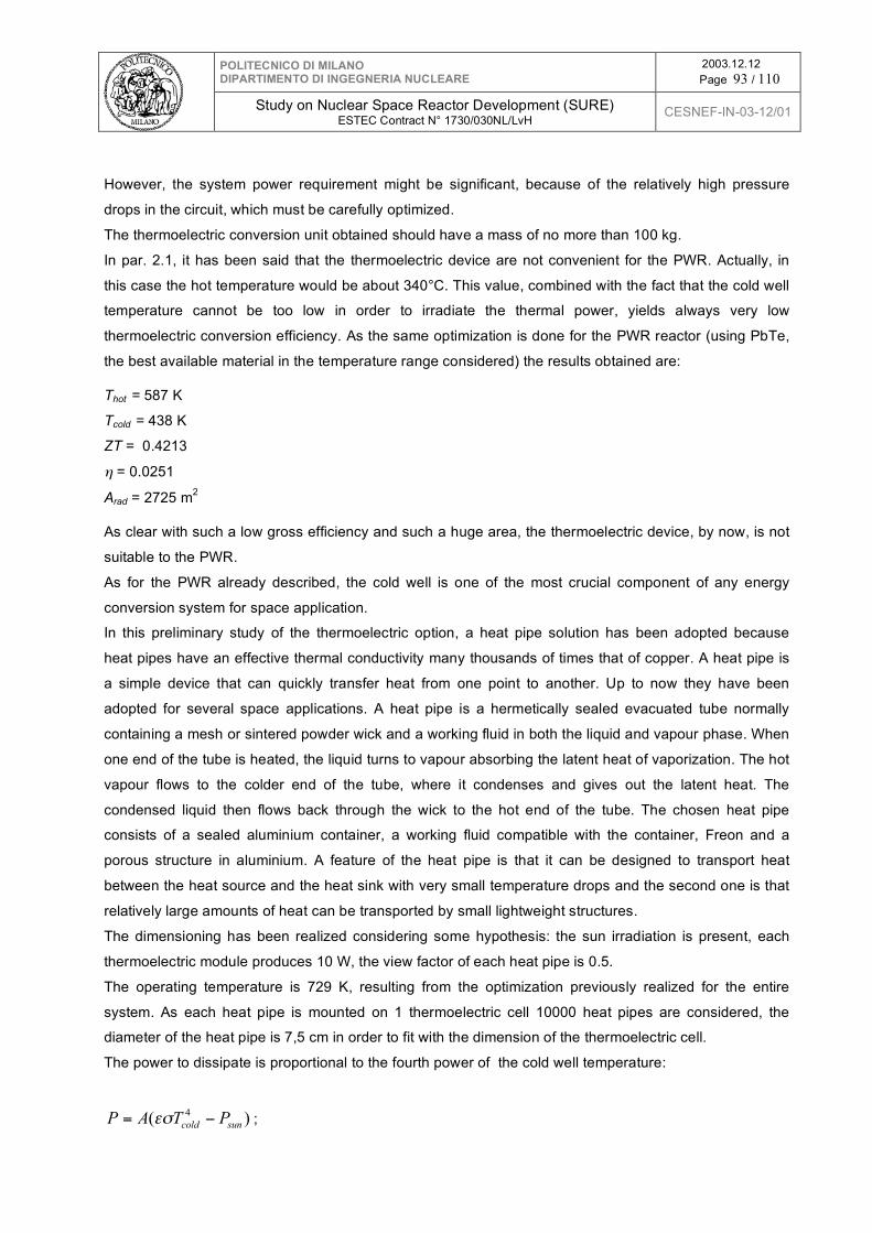
POLITECNICO DI MILANO DIPARTIMENTO DI INGEGNERIA NUCLEARE
2003.12.12 Page 93 / 110
Study on Nuclear Space Reactor Development (SURE)
ESTEC Contract N° 1730/030NL/LvH CESNEF-IN-03-12/01
However, the system power requirement might be significant, because of the relatively high pressure
drops in the circuit, which must be carefully optimized.
The thermoelectric conversion unit obtained should have a mass of no more than 100 kg.
In par. 2.1, it has been said that the thermoelectric device are not convenient for the PWR. Actually, in
this case the hot temperature would be about 340°C. This value, combined with the fact that the cold well
temperature cannot be too low in order to irradiate the thermal power, yields always very low
thermoelectric conversion efficiency. As the same optimization is done for the PWR reactor (using PbTe,
the best available material in the temperature range considered) the results obtained are:
Thot = 587 K
Tcold = 438 K
ZT = 0.4213
η = 0.0251
Arad = 2725 m2
As clear with such a low gross efficiency and such a huge area, the thermoelectric device, by now, is not
suitable to the PWR.
As for the PWR already described, the cold well is one of the most crucial component of any energy
conversion system for space application.
In this preliminary study of the thermoelectric option, a heat pipe solution has been adopted because
heat pipes have an effective thermal conductivity many thousands of times that of copper. A heat pipe is
a simple device that can quickly transfer heat from one point to another. Up to now they have been
adopted for several space applications. A heat pipe is a hermetically sealed evacuated tube normally
containing a mesh or sintered powder wick and a working fluid in both the liquid and vapour phase. When
one end of the tube is heated, the liquid turns to vapour absorbing the latent heat of vaporization. The hot
vapour flows to the colder end of the tube, where it condenses and gives out the latent heat. The
condensed liquid then flows back through the wick to the hot end of the tube. The chosen heat pipe
consists of a sealed aluminium container, a working fluid compatible with the container, Freon and a
porous structure in aluminium. A feature of the heat pipe is that it can be designed to transport heat
between the heat source and the heat sink with very small temperature drops and the second one is that
relatively large amounts of heat can be transported by small lightweight structures.
The dimensioning has been realized considering some hypothesis: the sun irradiation is present, each
thermoelectric module produces 10 W, the view factor of each heat pipe is 0.5.
The operating temperature is 729 K, resulting from the optimization previously realized for the entire
system. As each heat pipe is mounted on 1 thermoelectric cell 10000 heat pipes are considered, the
diameter of the heat pipe is 7,5 cm in order to fit with the dimension of the thermoelectric cell.
The power to dissipate is proportional to the fourth power of the cold well temperature:
)( 4
suncoldPTAP != "# ;

POLITECNICO DI MILANO DIPARTIMENTO DI INGEGNERIA NUCLEARE
2003.12.12 Page 94 / 110
Study on Nuclear Space Reactor Development (SURE)
ESTEC Contract N° 1730/030NL/LvH CESNEF-IN-03-12/01
the real area to consider is obtained dividing the theoretical area for the view factor:
Areal = 2 ⋅ Atheorical
The ratio between the total area of the radiators and the total area of the thermoelectric device should be
maintained on each heat pipe so the length, L of each heat pipe is easily obtained:
ξ = Areal / Athermoelectric cell
A heat pipe = π ⋅ D ⋅ L = ξ ⋅ A thermoelectric cell
The thickness of the container has been assumed t=0.75 mm, because of structural reasons. The radiator
obtained in order to dissipate 2119 KW (2219 -100 KW) is composed of 10000 heatpipes, of a theoretical
area of 159 m2 and of a real area of 318 m2, 135 mm long and of a total mass of 642 kg.
3.5 The primary system
The primary system differs substantially between the two reactors. However, both adopt a semi integrated
solution, where the rotating machines are put inside the pressure vessel. Then in the 417 KW reactor the
turbine, the compressor and the alternator are integrated inside the pressure vessel, while in the 2219
KW reactor the compressor and its own motor (see Fig.3.18 and 3.19).
750 °C
!
312 kWth
241 °C
900 °C
135 °C
T C
266 °C
725 °C
! 105 kWe
3 MPa
4,8 MPa
Fig. 3.18

POLITECNICO DI MILANO DIPARTIMENTO DI INGEGNERIA NUCLEARE
2003.12.12 Page 95 / 110
Study on Nuclear Space Reactor Development (SURE)
ESTEC Contract N° 1730/030NL/LvH CESNEF-IN-03-12/01
C
Fig. 3.19
This choice is based on the following considerations:
• to recuperate the small gas leakage from the turbomachines without the need of an ad hoc
containment and recharging compressor;
• to cool the pressure vessel walls by a relatively cold gas, otherwise the mechanical constrain
would result excessive, unless an ad hoc insulation is implemented to cover all over the inner
walls; this cooling can be done rather simply in the 417 KW reactor by making licking up the cold
gas on the inner pressure vessel wall; while in the 2219 KW one, an auxiliary circuit is necessary
to produce this small flow rate of rather cold gas following the same inner path.
• The 900 °C pipe is eliminated outside the vessel in the 417 KW reactor but not in the 2219 KW
one.
• The vessel mass is practically the same
The issues to be coped with by this choice are:
• the inlet and outlet nozzles are passed through by hot gas, (725 - 750 °C) and (725 - 900 °C) for
the 417 KW and 2219 KW reactor respectively and thus a reliable insulation solution for the wall
must be implemented;
• the same for the connecting pipes to the regenerator (417 KW) and the thermoelectric device
(2219 KW);
• the rotating machines work in high temperature environment and cannot be inspected and
maintained (in any case very difficult in space reactors);
• the above requirement seems more worrying for the alternator (417 KW) and the motor (2219
KW), which usually operate at room temperature and copper wires can be sensitive to
temperature.

POLITECNICO DI MILANO DIPARTIMENTO DI INGEGNERIA NUCLEARE
2003.12.12 Page 96 / 110
Study on Nuclear Space Reactor Development (SURE)
ESTEC Contract N° 1730/030NL/LvH CESNEF-IN-03-12/01
In this case also the best pressure vessel shape is the cylinder surmounted by hemispheric domes: the
inner dimensions are sketched in Figs.3.20 and 3.21 for the 2219 KW reactor and in Figs.3.22 and 3.23
for the 417 KW reactor.
Fig. 3.20
Fig. 3.21

POLITECNICO DI MILANO DIPARTIMENTO DI INGEGNERIA NUCLEARE
2003.12.12 Page 97 / 110
Study on Nuclear Space Reactor Development (SURE)
ESTEC Contract N° 1730/030NL/LvH CESNEF-IN-03-12/01
Fig. 3.22
Fig. 3.23

POLITECNICO DI MILANO DIPARTIMENTO DI INGEGNERIA NUCLEARE
2003.12.12 Page 98 / 110
Study on Nuclear Space Reactor Development (SURE)
ESTEC Contract N° 1730/030NL/LvH CESNEF-IN-03-12/01
3.5.1 The pressure vessel
The design pressure of the primary system is equal to the operating pressure multiplied a factor of 1.10,
which takes into account the value of the safety valve setting. This component is absolutely needed for
each pressurized system, but in our case implies an important issue concerning the consequences of its
operation in the case of pressure transients above 1.10 operating pressure, which means a discharge of
a substantial fraction of helium. For the time being we adopted a higher value than the usual one in order
to reduce the possibility of its intervention (1.10 against 1.07). The design pressure has been then set to
4.8x1.10 = 5.28 MPa.
On this basis the pressure vessel thickness have been determined using the same steel adopted in PWR,
i.e. stainless steel SA 508, Tp.3, Cl.2, with an allowable stress of 205 MPa7. The thickness are detailed in
par. 3.11 and the vessel mass turns out to be 890 kg and 736 kg for the 2219 and 417 KW reactors
respectively.
3.5.2 The regenerator
The regenerator is a crucial component both for the size, having a power of 2.76 times that of the reactor
(1151 against 417 KW), and the high temperatures and pressures involved (maximum values 750°C and
4.8 MPa). A detailed design of this component has not been carried out yet. From the relevant literature
we found that a plate fin exchanger with 6 fins/cm provides about 1300 m2 per cubic meter of volume.
Operated at a frontal velocity of 3 m/s, the heat transfer coefficient based on prime surface area would be
around 1.8 KW/m2 K. The average temperature drop is 25 °C. Therefore the overall surface is 26 m2.
Recalling the above surface over volume ratio, the overall volume results 0.02 m3. In other words that
means a cube of 27 cm side.
The pressure drops are to be verified once defined the exact geometry of the heat exchanger, however,
the assumed value of 0.01 of 4.8 and 3 MPa respectively of the two sides seems to be sufficiently high.
The remaining components are the safety valve, the control mechanism and the instrumentation. The
safety valve does not require particular consideration apart from the issue mentioned above about the
effects of its operation. The control mechanism will be addressed in the next paragraph. The
instrumentation can be considered rather conventional, but how to treat the relative information is an
open issue which should be considered in the following.
7 It might be a little higher because the temperature is lower than in PWR, but this is to be verified in detail.

POLITECNICO DI MILANO DIPARTIMENTO DI INGEGNERIA NUCLEARE
2003.12.12 Page 99 / 110
Study on Nuclear Space Reactor Development (SURE)
ESTEC Contract N° 1730/030NL/LvH CESNEF-IN-03-12/01
3.6 The reactivity control
For the reactivity control, the general considerations developed for PWR systems are still valid, apart the
solution to use boric acid dilution in the moderator, which obviously is not possible in this reactor, but
anyway it has been also excluded for other reasons in the PWR.
The reactivity excursions in these reactors are due to total reactivity difference between a cold condition
with the fuel at the Beginning Of Life (BOL) and the hot reactor at full power with the fuel at the End Of
Life (EOL). A logical subdivision of this reactivity variation is as follows:
1. Reactivity decrease going from cold condition to operating temperature;
2. Reactivity decrease from zero power to full power conditions (this term includes the absorptions
by Xe and Sm, which reach their equilibrium value in tenths hours);
3. Reactivity decrease along the fuel life to cope with reduction of fissile material and accumulation
of poisoning fission products;
4. Reactivity margin to control the reactor power.
The typical values for a commercial HTGRs are not well known, because their design is still in progress.
The values found in the present design are as follows:
Term 1 is small because the density variation in solid graphite between cold and operating temperature is
much lower than in water; Term 2 is relatively small because of the low temperature increase inside the
rod and the low thermal flux both the Doppler effect and the absorptions by Xe and Sm are of modest
impact. Term 3 is that shown in Figs. 3.8 and 3.9.
Like in the PWR solution, the only possibilities are burnable poisons and control rods. The first ones
require as already said in par.2.5 a detailed study, which is now postponed and its goal is to reduce the
overall reactivity to be controlled by the control rods. The latter can be inserted in the reflector as already
foreseen in some high power HTGRs. These rods can be imagined as rotating devices, as already
explained for the PWR solution, or channels flowed by a fluid made by poisoned graphite balls inserted or
extracted from the core reflector, by means of a suitable pneumatic mechanism.
The problem of reactivity control seems more viable than in the PWR reactor, however the lack of a
negative temperature coefficient may render the system control more delicate, implying in probably a
continuous operation of the control rods.
Tab. 3.3 : Reactivity terms in pcm.
Power (KW) 417 2219 Term 1 ~ 500 ~ 500 Term 2 ~ 300 ~ 500
Term 3 1700 7200 Term 4 ~ 0+ ~ 0+
Total 2500 8200

POLITECNICO DI MILANO DIPARTIMENTO DI INGEGNERIA NUCLEARE
2003.12.12 Page 100 / 110
Study on Nuclear Space Reactor Development (SURE)
ESTEC Contract N° 1730/030NL/LvH CESNEF-IN-03-12/01
3.7 Masses
In the previous sections the masses of the core, pressure vessel and cold well has been detailed for both
the 2219 and the 417 KW cores. We have not considered some further components of the complete
system yet, as for example the tubes, valves, auxiliary circuits, internals and so on. The mass of the other
not considered parts is globally assumed to be about 200 kg for both reactors.
At the end the mass of any single component has been increased of a margin of 5 % to take into account
any kind uncertainty or disregarded parts. The final sum has then been increased by a further 10 % as a
contingency. The detailed values are shown in Tab3.4.
Tab. 3.4 : Masses in kg of HTGR
2219 KW 417 KW
Fuel 268 + 268 +
Moderator 1746 + 1378 +
Reflector 574 502
Core+reflector = 2588 + = 2148 +
Vessel 890 + 736 +
Overall reactor = 3478 + 5 % 3652 = 2884 + 5 % 3028
Cold well 642 + 5 % 674 742 + 5 % 779
Compressor 100 + 5 % 105 100 + 5 % 105
Turbine / Thermoelectric devices 100 + 5 % 105 100 + 5 % 105
Other components 200 + 5 % 210 200 + 5 % 210
Overall system 4746 4227
Contingency = 10 % 475 423
Total Mass of the System 5221 4650
3.8 Preliminary safety consideration
A detailed safety analysis is outside the scope of this feasibility study, for its complexity and need to
define the detailed requirements. In fact this reactor from one side is nor subjected to the licensing
procedure of terrestrial reactors imposed by the safety authorities, from the other it must satisfy specific
safety issues connected to its launch and the possibility to fall down to the earth.

POLITECNICO DI MILANO DIPARTIMENTO DI INGEGNERIA NUCLEARE
2003.12.12 Page 101 / 110
Study on Nuclear Space Reactor Development (SURE)
ESTEC Contract N° 1730/030NL/LvH CESNEF-IN-03-12/01
In the foreword it is mentioned that this nuclear system must satisfy the usual safety requirements of
terrestrial reactors and this is what is to be defined in detail, taking into account the above consideration
about the lack of a licensing procedure. Besides this the system has to assure that:
- no irradiated fuel is present at launch;
- the core sub criticality in the case of possible launch accidents (flooding);
- the radiation protection without impairing mass requirements;
- an easy decommissioning in space;
The first item is inherently satisfied, because the reactor would not reach its first criticality before being
outside terrestrial space. The second one is a rather crucial one, because it requires the need to insert
high absorbing materials in the core, to be extracted when the reactor will start up. Probably this is a
rather demanding requirement, which deserves a specific consideration.
The third is a an important issue, which can be addressed only after having defined some conditions,
especially for the propulsion solution. In fact, for surface reactor, the shield cannot be transported from
the earth and it is to be provided by a suitable system layout on the Mars surface (regoliths around,
underground siting, big distances). For propulsion reactor an intermediate solution is to be found by
balancing the addition of a small shield around the core with the reduction of the radiation danger by
locating the reactor far away from the sensible zone (a separate capsule for the reactor?) or by locate an
extra shield only on the reactor portion viewed by the sensible zone.
The fourth one is too indefinite at this stage of the design, that no specific consideration can be drawn.
These reactors have the inherent feature to resist to the consequences of a LOCA, without provoking the
fuel melting. It is well known that fuel melting represents the most feared situation for terrestrial reactor,
and the nowadays attitude for new reactor designs is to avoid this in any foreseeable circumstance, as it
happens in these reactors by adopting a relatively high value of the ratio lateral surface over volume of
the core. In fact, this choice limits the power of these reactors to 200÷300 MWth range. In a complete loss
of coolant, the fuel and the core heat up and the reactivity goes down till the complete shut down of the
neutronic chain, but the fuel goes on producing some power, the so called decay heat. Actually this
transient is to be verified in this reactor because of its very low temperature coefficient. If this is the case,
the fuel temperature rise is curbed by the thermal radiation of the core toward the vessel and from the
latter towards the nearby environment. Since the fuel resists to very high temperature without undergoing
damages or ruptures, there is no need of any protection system intervention.
However, in the case of a LOCA in a terrestrial reactor it is necessary to avoid the air entrance into the
core, otherwise the graphite reaching high temperature reacts with the oxygen of the air and burns.
However, in the literature it is mentioned the fact that high purity nuclear grade graphite reacts very slowly
with oxygen and it will be classified as non combustible by conventional standard. This potential danger in
terrestrial reactors is coped with different protection actions and in particular a containment, the goal of
which is to avoid the air entrance into the core. In the present reactor, the danger is not well defined,
because in propulsion application there is no atmosphere and in surface application the exact
composition of the atmosphere is not well known. Anyway this issue deserves attention.

POLITECNICO DI MILANO DIPARTIMENTO DI INGEGNERIA NUCLEARE
2003.12.12 Page 102 / 110
Study on Nuclear Space Reactor Development (SURE)
ESTEC Contract N° 1730/030NL/LvH CESNEF-IN-03-12/01
3.9 Open issues and R&D needs
This feasibility study has allowed us to find the open issues to be solved for going on this route, which
needs a R&D program. Here below a list of them, which is inevitably incomplete, is detailed; the order is
not based on their importance. The fuel is identical to that foreseen in terrestrial reactors, and then it can
be assumed that it is or will be developed by already existing R&D programs.
The issues written in bold letters are those interesting for terrestrial reactors and those written in italic
those interesting for generic terrestrial applications as well.
- Reactor vessel internal layout: temperature distribution, wall cooling, internal passages,
mechanical design;
- Pipe design to resist to high temperature flowing fluids;
- Increase of operating pressure: primary circuit materials;
- The cold well as cooler
- The cold well associated to thermoelectric device;
- Heat pipes
- Gas turbine and compressor working in high temperature environment;
- Alternator working in high temperature and pressure environment;
- Thermoelectric apparatus;
- Fluid leakage: how much, how to cope with;
- Maintenance requirements of the whole system; - Optimum reflector: technological aspects
- Fluence effects on vessel in these particular conditions;
- Shielding;
- Safety valves: reliability, how to cope their intervention;
- Vessel material different from stainless steel;
- The regenerator: thermal, mechanical corrosion issues;
- Control rods;
- Control of the system and of the reactor and its constructive implications;
- Flooding danger avoidance.
The R&D about thermoelectricity at high temperature is of paramount importance for this reactor,
because if present net efficiency (gas pressure drops may require high compressor power absorption)
can be improved and assure the long term reliability by a suitable choice of materials, a thermoelectric
apparatus might became the right solution for this nuclear system, instead of the much more complex
Brayton cycle. Moreover, if the improvements may be obtained also at lower temperatures as those
typical of PWRs, the present choice to eliminate this option for these reactors should be reconsidered.
Even if this list is incomplete, no item seems to be unsolvable, and the lack of fuel development activity is
greatly advantageous. On the other hand, some high temperature design issues appear demanding
especially for long term operation. An R&D program of reasonable extent may yield the needed answers,

POLITECNICO DI MILANO DIPARTIMENTO DI INGEGNERIA NUCLEARE
2003.12.12 Page 103 / 110
Study on Nuclear Space Reactor Development (SURE)
ESTEC Contract N° 1730/030NL/LvH CESNEF-IN-03-12/01
but what is important that the most demanding researches also are of interest for the new generation
High Temperature Gas Reactors. Then a cost sharing action can be proposed and duly programmed,
according to the time schedule of the commercial exploitations of these terrestrial reactors.
3.10 Concluding remarks
At the end of this very preliminary feasibility study about the use of HTGR system for space reactors, it
can be concluded that no insoluble issues have been evidenced, which would prevent of going on along
this route in order to execute a more detailed design. Then it will be possible to draw a more justified
conclusion about the usefulness to follow this solution.
At the beginning of the study it was supposed that the solutions for propulsion and surface application
might be the same. Actually, it seems that this hypothesis holds more in this reactor than in PWR,
because the lack of gravity does not determine any particular detriment to reactor operation. However, it
remains the need of an autonomous radiation shield, which in surface reactors can be provided by the
existence of a soil. On the other side the safety problem connected to a possible flooding seems rather
demanding, also because the fuel cannot be separated from the moderator during the launch phase.
If it will be confirmed in prosecution of the work that no insoluble issues are present in this proposal, it can
be stated that a reasonable R&D effort and consequently a relatively limited development cost and time
interval are only needed in this case.
In the short range, future design activities should address the detailing of many aspects of the analysis
presented in this report and adding new ones. The new activities are: radiation shielding, vessel fluence,
control, safety aspects, cold well (in forced convection as well), choice of vessel material, vessel layout,
system layout, regenerator design, containment, leakage control, ancillary circuits for start up, coolant
purification and other exigencies. Moreover, at the end of this further activity a preliminary R.&D. program
should be detailed.

POLITECNICO DI MILANO DIPARTIMENTO DI INGEGNERIA NUCLEARE
2003.12.12 Page 104 / 110
Study on Nuclear Space Reactor Development (SURE)
ESTEC Contract N° 1730/030NL/LvH CESNEF-IN-03-12/01
3.10 . HTGR reactor list of data
HTGR - 2219 HTGR - 417
Power
Thermal [KW] 2219 417
Electric [KW]
Primary circuit
Fuel
Composition
Enrichment BOL
Enrichment EOL ~83% ~91%
Diameter [ì m]
Rod geometry
Apothem [mm]
Cladding
Material
Fuel-moderator-coolant channel
Geometry
Apothem [mm] 32,7 29,4
# of fuel rod / coolant holes
Holes apothem
Height [mm] 1113 1037
Moderation ratio 9,5 7,5
total # of fuel rod 1590 1686
Burnup [MWD/kg] 100 20
Pressure
P max [MPa]
P min [MPa] (assumed)
Compression ratio
Temperatures
T max [°C] (assumed)
T min [°C] (assumed)
Secondary circuit
Cold well temperature [°C] 456 135 - 266
Thermodinamic cycle Thermoelectric Brayton
Net efficiency [%] 4,5 24
Thickness [ì m]
Density [kg/m3]
1,6
4,8
3
900
725
100
UO2 sintered in micro spheres
93%
350
4 carbon based layers
Hexagonal
4,1
1800
6 / 1
3,8
Hexagonal
400

POLITECNICO DI MILANO DIPARTIMENTO DI INGEGNERIA NUCLEARE
2003.12.12 Page 105 / 110
Study on Nuclear Space Reactor Development (SURE)
ESTEC Contract N° 1730/030NL/LvH CESNEF-IN-03-12/01
Miscellaneous data
UO2 Fuel quantity [kg]
Specific power [KW/kg] 22,19 4,17
Reflector
Material
Thickness [mm]
Core designs
keff (EOL) (assumed)
Mass (core+reflector) [kg] 2588 2148
Electrical power generation
Working fluid /// He
Inlet reactor temperature [°C]
Outlet reactor temperature [°C]
Turbine efficiency /// 0,80
Compressor efficiency
Regenerator efficiency /// 0,95
Minimum pressure [MPa] /// 3
Pressure drops ( deltap/p ) /// 0,01
Cold well
Type Heat pipes Bundle of tubes
Tube geometry
Inner diameter [mm] 73,6 6
Outer diameter [mm] 75 7
Length [m] 0,13 30
Tube number 10000 450
Pressure drop [KPa] /// 30
Internal pressure [MPa] /// 0,7
Pressure drops ( deltap/p ) /// 0,01
Temperature [°C] 456 135 - 266
Specific power [KW/m2] /// 1,16
View factor 0,5 0,6
Surface area [m2] 317 273
Material Aluminium Titanium
Mass [kg] 642 742
Mass per unit radiating surface [kg/m2] 2,03 2,72
Cold well dimension (cylinder)
height [m] /// 7
diameter[m] /// 4
Reactor vessel
Design pressure [MPa]
Material
Thickness [mm]
Cylindrical portion [mm] 15,9 14,9
Spherical portion [mm] 7,9 7,5
100
725
900
0,80
5,28
SA 508, TP.3, Cl.2
50
1,01
Graphite

POLITECNICO DI MILANO DIPARTIMENTO DI INGEGNERIA NUCLEARE
2003.12.12 Page 106 / 110
Study on Nuclear Space Reactor Development (SURE)
ESTEC Contract N° 1730/030NL/LvH CESNEF-IN-03-12/01
Vessel mass [kg] 890 736
Core+reflector mass [kg] 2588 2148
Overall vessel mass [kg] 3478 2884
Regenerator
Surface [m2] /// 26
Volume [m3] /// 0,02
Reactivity control
Term 1 [pcm]
Term 2 [pcm] 500 300
Term 3 [pcm] 7200 1700
Term 4 [pcm]
Total [pcm] 8200 2500
Masses [kg] (+5%)
Overall reactor mass 3652 3028
Cold well 674 779
Compressor
Turbine+alternator/Thermoelectric devices 105 105
Other components
Overall system 4746 4227
Contingency (10%) 475 423
Total 5221 4650
500
~ 0+
105
210

POLITECNICO DI MILANO DIPARTIMENTO DI INGEGNERIA NUCLEARE
2003.12.12 Page 107 / 110
Study on Nuclear Space Reactor Development (SURE)
ESTEC Contract N° 1730/030NL/LvH CESNEF-IN-03-12/01
4. COMPARISON BETWEEN THE TWO PROPOSALS
The critical comparison between the two solutions here proposed is difficult to carry out without any
external information about specific technological issues.
Let us start with the PWR. The crucial issues are:
• The fuel;
• The steam turbine;
• The reactivity control;
• The pressurizer (only for propulsion solution).
The fuel is not a real technical issue, apart from the need to test it in a long irradiation program. As said
in the introduction, the rod diameter is so small with respect of usual UO2 rods, that a verification program
is necessary, even if no particular difficulties can be envisaged. However, other fuel alternatives are
possible, thanks to the high enrichment. For instance, instead of uranium oxide it is possible to imagine
the use of a high alloyed uranium metal, as the one already studied for fast reactors and probably
extensively used in submarine propulsion. In this case the geometry can be different from a rod as a
curved plate, many of them suitably assembled is square boxes (Material Testing Reactor type).
Therefore, there are two possibilities: i) if the already existing information about fuel adopted for special
reactors will become available, no specific R&D program is needed; ii) if this is not the case, a rather long
and expensive R&D program is needed in order to obtain the green light to adopt this new fuel.
The steam turbine is of paramount importance for this system. These small turbines are not yet
developed, even if there is no particular reason to not reach such a goal, taking into account that some
decrease of their efficiency is acceptable in this application. In particular, there is the leakage issue, which
can impair the long term reliability of the overall system: it is difficult to build perfectly sealed components,
when they are connected to outside by rotating shafts, as that which connects the turbine to the
alternator. Anyway the leakage issue applies to the primary system as well, because losses of water are
possible across the pressure vessel penetrations, necessary for the instrumentation electrical cables, and
for the control mechanism (this may require a mechanical rotating shaft crossing the pressure barrier or
an electrical cable in the case of using electrical motors inside the pressure vessel). Finally, the alternator
may require some cooling need, not easily solvable in the space.
The reactivity control has been already discussed in par.2.5, however let us here recall the crucial
mechanical aspects of this system.
The pressurizer working in absence of gravity, where steam and water cannot separate each other, is a
demanding component and then for this reason no proposal has been studied in this report.
Passing to HTGR system the crucial issues are:
• High temperature components;
• Leakage;
• Thermoelectric generator;
• Criticality during flooding:

POLITECNICO DI MILANO DIPARTIMENTO DI INGEGNERIA NUCLEARE
2003.12.12 Page 108 / 110
Study on Nuclear Space Reactor Development (SURE)
ESTEC Contract N° 1730/030NL/LvH CESNEF-IN-03-12/01
The fuel in this case is not a problem, because the elemental micro sphere is absolutely identical to that
foreseen for commercial reactors. Maybe some more verifications and tests are necessary, but this will be
done by the R&D programs associated to these commercial reactors. Moreover the limited constrains of
this reactor fuel is a further assurance that the required specification will be met.
The high temperature is a big constrain for this reactor. In principle, there is no differences in this
framework with the analogous commercial reactors. However, the high and durable reliability here
required, together with a certain perplexity that in the commercial reactors they will be able to reach
completely such a high temperature value, raise preoccupations about this issue.
The gas leakage seems more important in this reactor than in the previous one, because the helium is a
mobile gas and difficult to collect, once escaped from the system. It is an aspect which requires a careful
analysis. In principle, it may be supposed that this issue is more crucial for the Brayton cycle case than
for that of the thermoelectric generator.
The latter is the hope and the problem of this reactor. If a reasonable net efficiency connected to a high
reliability and durability can be demonstrated by such a device operating at high temperatures, a big push
in favor of this reactor will be obtained.
The criticality danger during an accidental fall down into the sea, is not an easy task to cope with. This
issue has not be analyzed in detail in this study and then a further analysis is needed before drawing
founded conclusions.
In the above, the cold well issue has not been mentioned for both reactors. Two are the reasons: i) it is
believed that this is an optimization problem, maybe difficult and demanding one, but not unsolvable, ii)
the component is not specific to these reactors and so a general and generic R&D program should be
launched for this component.
In conclusion, it is clear from the above considerations how much determinant can be the contribution of
already existing experience and knowledge to simplify substantially the R&D program needed for these
reactors, but this is out of our reach.
It is probable that PWR is less suited for propulsion than for surface application, because of the lack of
gravity, which makes the pressurization control a complex task. On the other hand, maybe the a priori
better reliability of such a reactor makes it more fit for surface application than the HTGR. As for the masses, higher values are obtained for the HTGR, but the uncertainties of this estimation and
the need of further ancillary components and circuits are probably higher than the differences with the
PWR masses. However, an important aspect is the very low influence of the power level on the overall
core mass of the HTGR system, which, if confirmed, may become an advantageous item by increasing
the power.

POLITECNICO DI MILANO DIPARTIMENTO DI INGEGNERIA NUCLEARE
2003.12.12 Page 109 / 110
Study on Nuclear Space Reactor Development (SURE)
ESTEC Contract N° 1730/030NL/LvH CESNEF-IN-03-12/01
References
1. “WIMSD, A Neutronics Code for Standard Lattice Physics Analysis”, AEA Technology, distributed
by the NEA Databank.
2. J.F. BRIESMEISTER, “MCNP - A General Monte Carlo N-Particle Transport Code, Version 4C”,
LA-13709-M, Los Alamos National Laboratory (2000).
3. J.M. KUJAWSKI, D.M. KITCH, L.E. CONWAY, “The IRIS Spool-Type Reactor Coolant Pump”,
Proc. of ICONE10, 10th International Conference on Nuclear Engineering, paper #22572, CD-
ROM, Arlington, VA, (2002).
4. B. BRIGOLI, C. LOMBARDI and M.R. MONZANI, “Temperature Distributions in Dry PWR Cores”,
Energia Nucleare, 10, 3, 9-19 (1993).
5. Information System Laboratories (ISL), “RELAP5/MOD3.3 Code Manual”, Vol 1-8, NUREG/CR-
5535, USA, 2001.
6. D. I. POSTON, “Nuclear design of the SAFE-400 Space Fission Reactor”, Nuclear News, Dec
2002 pag 28-35.
7. Several references concerning description of space capsules powered by fission reactor system
8. ANGELINO, G. et al, “Organic Working Fluid Optimization for Space Power Cycles” Book
published by Department of Energy of Politecnico di Milano in honor of professor Casci, 1985.
9. M. D. CARELLI, “IRIS: A Global Approach to Nuclear Power Renaissance”, Nuclear News, Sept.
2003, pg 32-42.
10. EPRI Steam Generator Progress Report - Revision 13 – EPRI Palo Alto, MCY 1998.
11. M. P. LABAR, et al, “The Gas Turbine Modular Helium Reactor”, Nuclear News, October 2003,
pg 28-37.

POLITECNICO DI MILANO DIPARTIMENTO DI INGEGNERIA NUCLEARE
2003.12.12 Page 110 / 110
Study on Nuclear Space Reactor Development (SURE)
ESTEC Contract N° 1730/030NL/LvH CESNEF-IN-03-12/01