
ES3_Simpson
24
The design of cost- effective pico-propeller turbines for developing countries Dr Robert Simpson, Dr Arthur Williams Nottingham Trent University, UK
description
http://www.esha.be/fileadmin/esha_files/documents/workshops/hidroenergia/ES3_Simpson.pdf
Transcript of ES3_Simpson

The design of cost-effective pico-propeller turbines for developing
countries
Dr Robert Simpson, Dr Arthur Williams
Nottingham Trent University, UK

Project overview
Aim: “to provide an accurate design and design method for the cost-effective manufacture of pico-propeller turbines (<5kW) in developing countries that is scaleable for a range of hydrological conditions”Project partner: Practical Action Peru (formerly known as Intermediate Technology Development Group)Funded by the Leverhulme Trust (UK trust organisation)

MotivationLow head hydro sites (2 to 10m) have great potential for providing electricity in rural areas of developing countries BUTprogress appears to be hampered by the lack of a cost-effective reliable turbine design that is appropriate for local manufacture in developing countriesMuch is known about the design of large Kaplan and propeller turbines but there is little published regarding the design of very small propeller turbines

ObjectivesUnderstand fully the design scale effects for pico-propeller turbines using CFD modeling, laboratory experiments and field testingInvestigate, make and test design simplifications and improvements to be implemented in the field and laboratoryProduce a design manual and simple computer program that can be used by local manufacturers and engineers Disseminate the information and results of the project which will be made freely available

Stage One
Specify a prototype turbine design based on current knowledge Turbine manufacture, installation and field testing (conducted with Practical Action Peru)Analysis of the turbine performance and investigation of possible improvements using Computational Fluid DynamicsMake modifications to the turbine and compare the field test data to CFD simulations
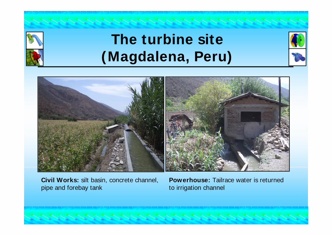
The turbine site(Magdalena, Peru)
Civil Works: silt basin, concrete channel, pipe and forebay tank
Powerhouse: Tailrace water is returned to irrigation channel
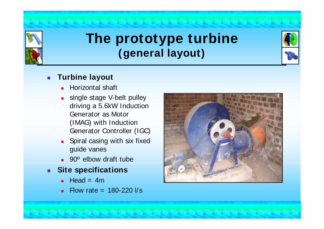
Turbine layoutHorizontal shaftsingle stage V-belt pulley driving a 5.6kW Induction Generator as Motor (IMAG) with Induction Generator Controller (IGC)Spiral casing with six fixed guide vanes 90º elbow draft tube
Site specificationsHead = 4mFlow rate = 180-220 l/s
The prototype turbine(general layout)

Original rotor designDiameter: 290mmBlades fabricated from flat plate steel (6mm thick)Blade profile created by bending and twisting the plate to produce camber and twistno nose coneNon-contact seal, with water allowed to leak during operation
The prototype turbine(Rotor design)
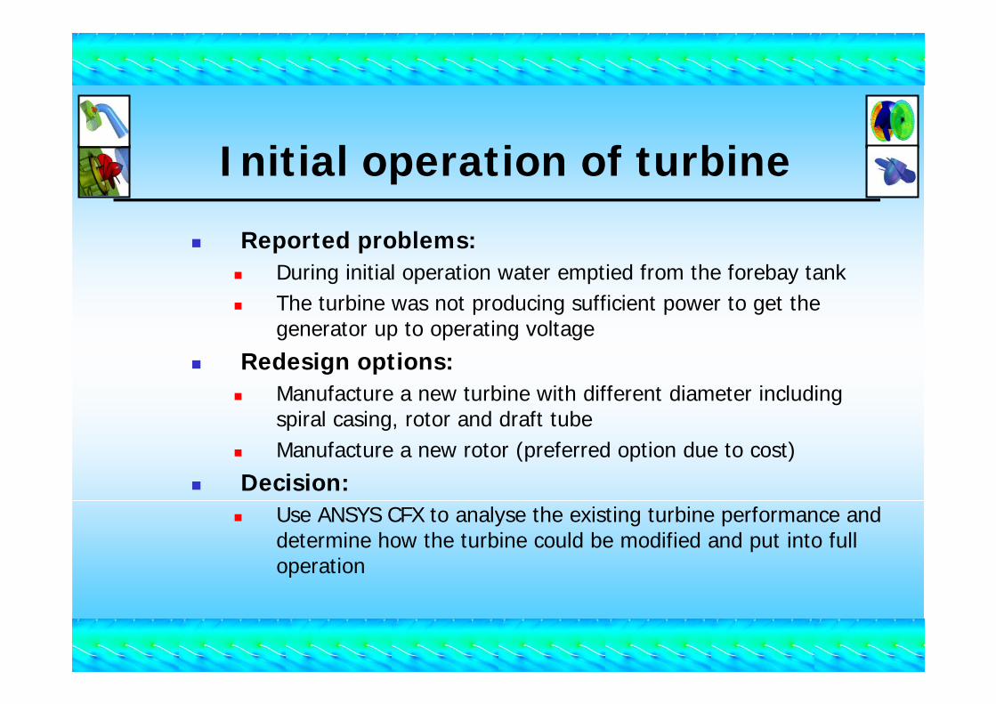
Initial operation of turbine
Reported problems:During initial operation water emptied from the forebay tankThe turbine was not producing sufficient power to get the generator up to operating voltage
Redesign options:Manufacture a new turbine with different diameter including spiral casing, rotor and draft tube Manufacture a new rotor (preferred option due to cost)
Decision:Use ANSYS CFX to analyse the existing turbine performance and determine how the turbine could be modified and put into full operation
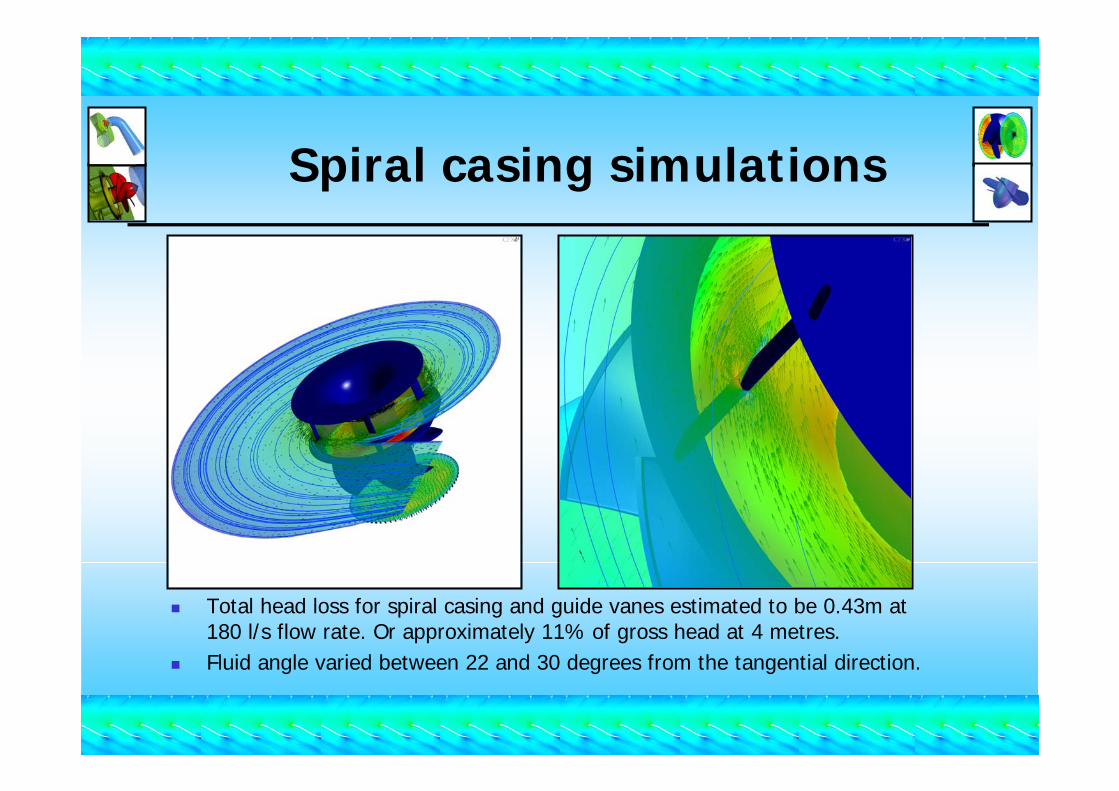
Spiral casing simulations
Total head loss for spiral casing and guide vanes estimated to be 0.43m at 180 l/s flow rate. Or approximately 11% of gross head at 4 metres.Fluid angle varied between 22 and 30 degrees from the tangential direction.
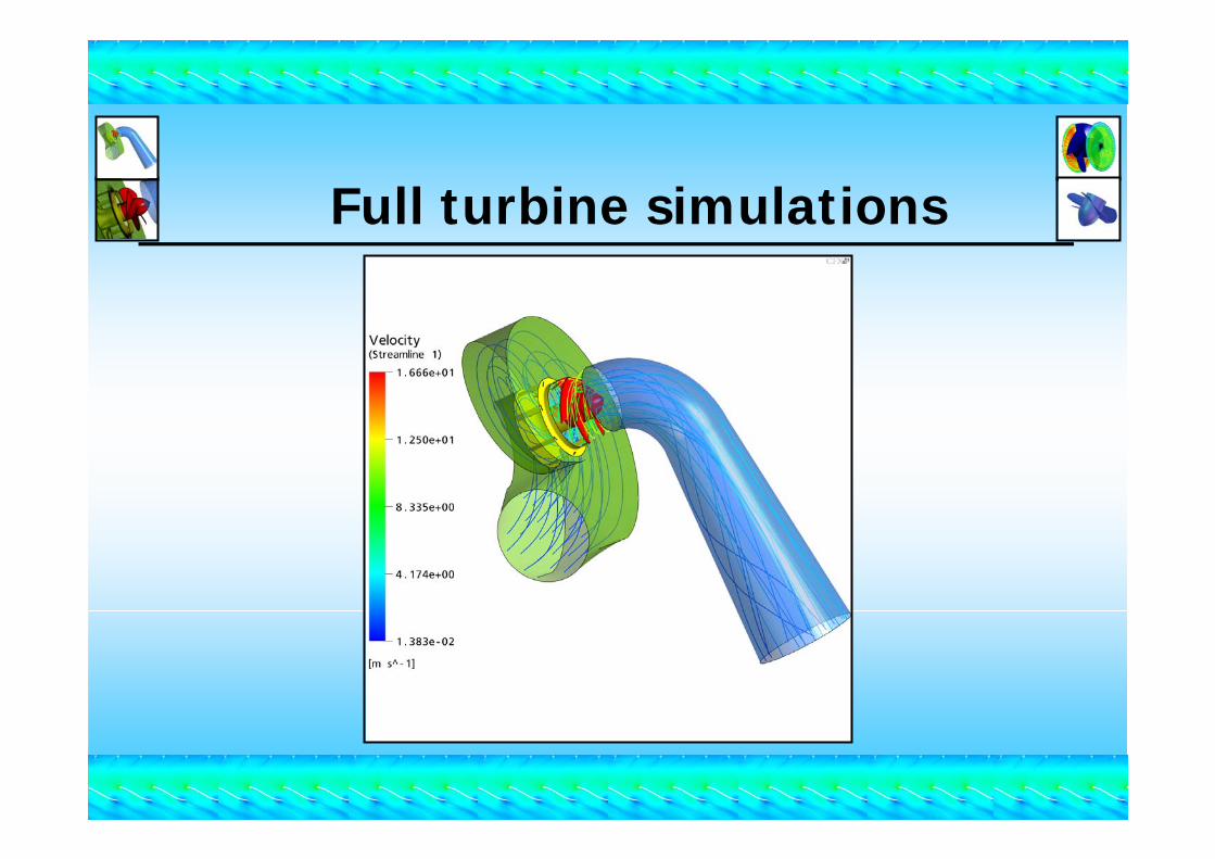
Full turbine simulations
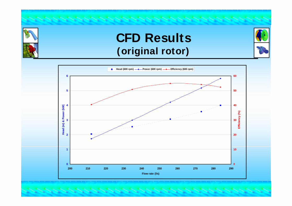
CFD Results(original rotor)
0
1
2
3
4
5
6
200 210 220 230 240 250 260 270 280 290
Flow rate (l/s)
Hea
d (m
) & P
ower
(kW
)
0
10
20
30
40
50
60
Effic
ienc
y (%
)
Head (600 rpm) Power (600 rpm) Efficiency (600 rpm)
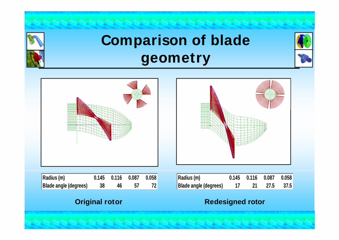
Comparison of blade geometry
Radius (m) 0.145 0.116 0.087 0.058Blade angle (degrees) 17 21 27.5 37.5
Radius (m) 0.145 0.116 0.087 0.058Blade angle (degrees) 38 46 57 72
Original rotor Redesigned rotor
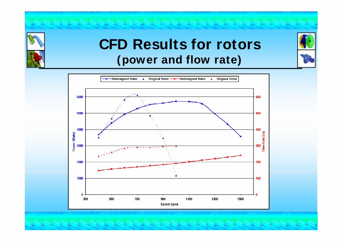
CFD Results for rotors(power and flow rate)
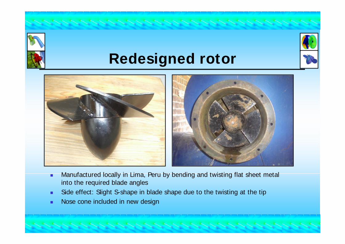
Redesigned rotor
Manufactured locally in Lima, Peru by bending and twisting flat sheet metal into the required blade angles Side effect: Slight S-shape in blade shape due to the twisting at the tipNose cone included in new design
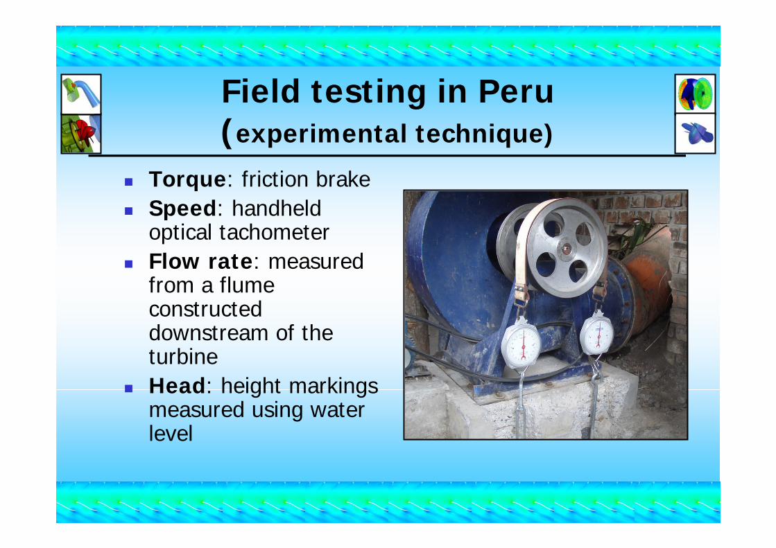
Field testing in Peru (experimental technique)
Torque: friction brakeSpeed: handheld optical tachometerFlow rate: measured from a flume constructed downstream of the turbineHead: height markings measured using water level
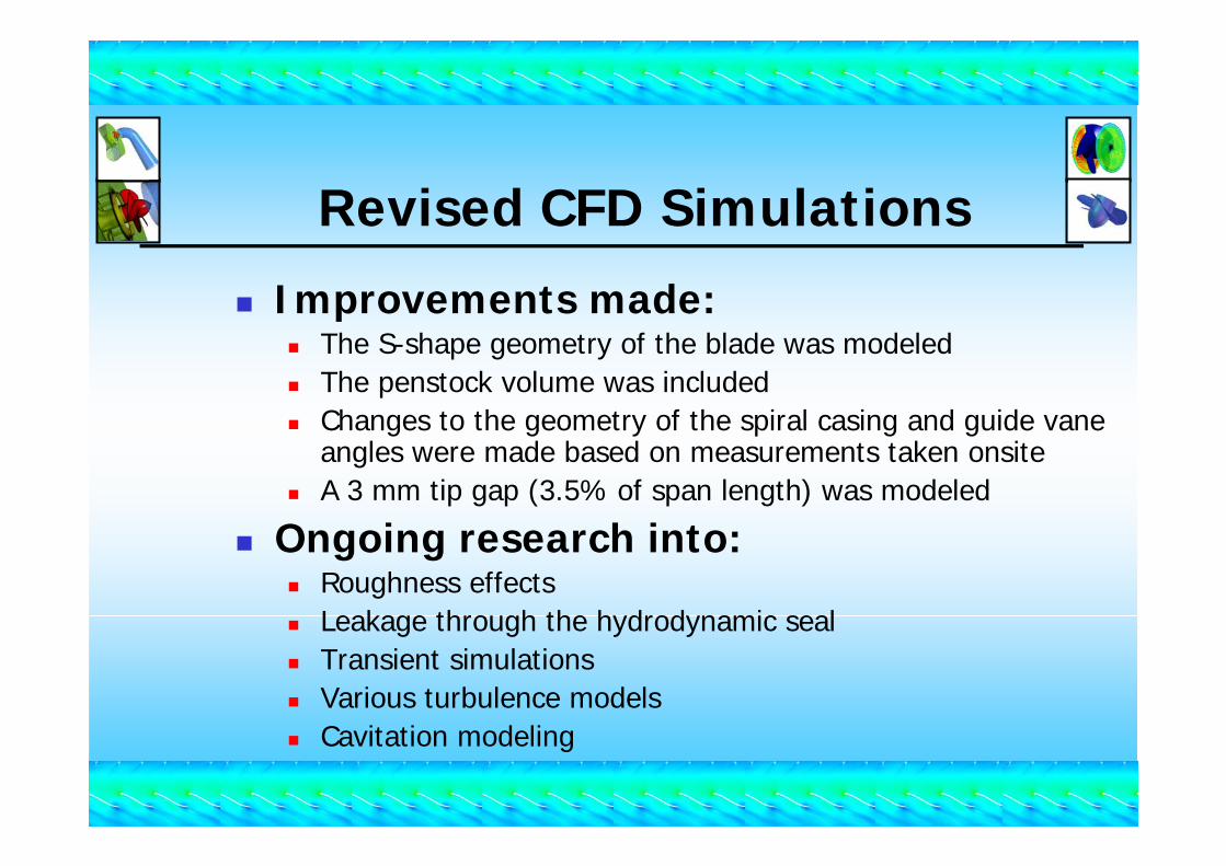
Revised CFD Simulations
Improvements made:The S-shape geometry of the blade was modeledThe penstock volume was includedChanges to the geometry of the spiral casing and guide vane angles were made based on measurements taken onsiteA 3 mm tip gap (3.5% of span length) was modeled
Ongoing research into:Roughness effectsLeakage through the hydrodynamic sealTransient simulationsVarious turbulence modelsCavitation modeling
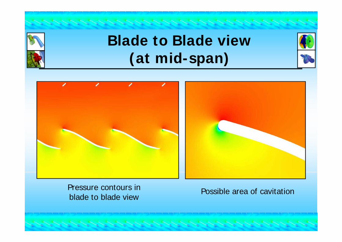
Blade to Blade view(at mid-span)
Pressure contours inblade to blade view
Possible area of cavitation
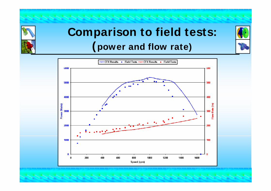
Comparison to field tests: (power and flow rate)

CFD Results:turbine component losses
Percentage of Gross Head (4 metres)(speed=800rpm)
Power output75%
Losses25% Tailrace
4%
Rotor5%
Spiral casing and guide vanes
11%Penstock
1%
Draft Tube4%
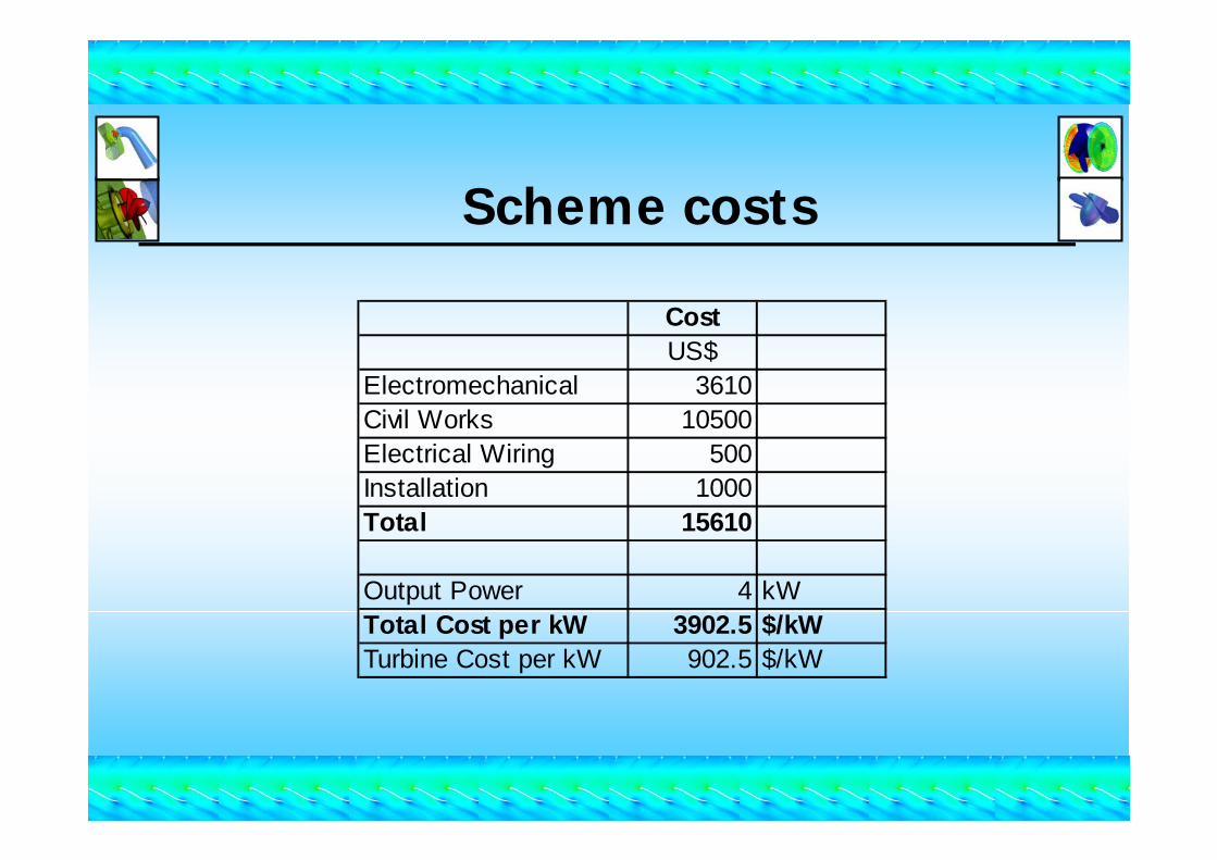
Scheme costs
CostUS$
Electromechanical 3610Civil Works 10500Electrical Wiring 500Installation 1000Total 15610
Output Power 4 kWTotal Cost per kW 3902.5 $/kWTurbine Cost per kW 902.5 $/kW
Conclusions and Future WorkConclusions
CFD analysis has been used to identify operational problems with the prototype turbine and has proved to be a useful tool for analysing new rotor geometries.The CFD simulations give a reasonable predicted performance for power output until the maximum power point, however, the flow rate is under predicted resulting in an over estimation of the turbine efficiency by 10%.
Future WorkFurther investigation into producing a profiled rotor with better cavitation performance as well as improvements to the CFD models.Detailed laboratory testing will be used to complement the CFD results and field tests
Miniature perspex turbine (200W) for a detailed investigation with Laser Doppler AnemometrySpiral casing propeller turbine of similar construction to the Peruvian prototype (1kW)Axial flow pump as turbine (approx. 1-2 kW)
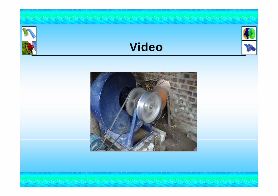
Video
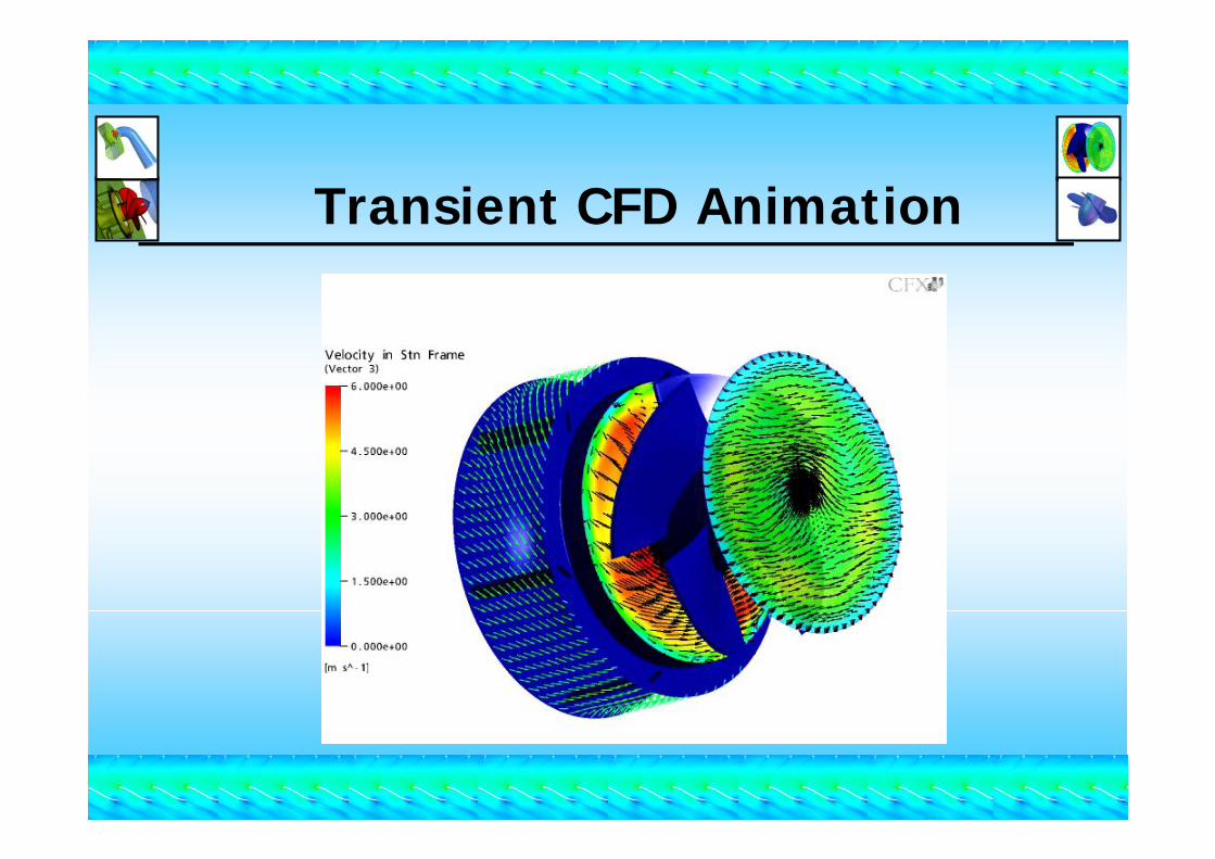
Transient CFD Animation


