ES General Wiring - Lancair
19
Lancair International Inc., Represented by Neico Aviation Inc., Copyright 2008 Redmond, OR 97756 Chapter 23 Page 23.1 REV. 2nd Ed./08-15-2006 General Wiring ES Chapter 23 General Wiring 23.1 Introduction This chapter covers the necessary wiring to get your Lancair ES functional. We will show you how to get power to the engine starter, then after the engine is fired up, how to get the power from the alternator into the cockpit. From this point various systems, such as lights, trim systems, fuel pump, flaps, etc., will be shown in wiring diagrams from the cockpit. In addition, the basic goal of this chapter is to acquaint you with important parts of the electrical system, such as the alternator, starter and master solenoid, mag switch, and the primary and avionics power sources (buses). Wiring can be one of the most intimidating of all the skills you learn when constructing a homebuilt aircraft. What makes matters even worse is that when you ask three different wiring "experts" about the best way to wire an alternator system, you will most likely receive three different answers. If you plan on wiring your own Lancair ES, start reading! Tony Bingelis is the guru of homebuilding "how to". Robert Nuckolls is also an excellent reference for wiring. He publishes a newsletter, The AeroElectric Connection, and also contracts his services to individual builders to design custom electrical schematics. He can be reached at: Medicine River Press 6936 Bainbridge Road Wichita, Kansas 67226-1008 Phone:(316) 685-8617 Another popular option is to have a local electrical professional complete your electric system for you. This is generally a good idea at least for the radio stack wiring, but for the basic electrical system in your Lancair ES, you might be surprised how simple it is to wire. Wire sizes are not provided on any of the wiring diagrams in this chapter. There can be different sizes used in either 12 or 24 volt systems. As a general guide we have reprinted the official FAA wire sizing chart for continuous circuit voltage. Determining the Wire Size To find the proper wire size you need to know the following: 1. First you need to know the amperes required for that circuit. The circuit breaker size shown in this chapter's schematics can be used for this figure. 2. Second, you'll need to figure out a rough estimate of the wire length from the master bus to the device being powered (landing light, boost pump, etc.). With these two numbers, you can find the minimum wire size required by looking at the chart. Here's an example: If you mount the landing light (10-amp breaker) in the cowling (about 10' wire length), the chart will tell you to use 16-gauge wire (rounding to the larger size) for a 12/14 volt system. 23.1 Introduction . . . . . . . . . . . . . . . . . . . . . . . . . . . . . . . . . . . . . . 23.1 23.2 Parts List . . . . . . . . . . . . . . . . . . . . . . . . . . . . . . . . . . . . . . . . 23.2 23.3 Construction Procedures . . . . . . . . . . . . . . . . . . . . . . . . . . . . 23.3 23.3.A Using the Wire Sizes Diagram. . . . . . . . . . . . . . . . . . . . 23.3 23.3.B Battery Box Options. . . . . . . . . . . . . . . . . . . . . . . . . . . . 23.4 23.3.C Basic Wiring Techniques . . . . . . . . . . . . . . . . . . . . . . . . 23.6 23.3.D Wiring the Flaps . . . . . . . . . . . . . . . . . . . . . . . . . . . . . . 23.9 23.3.E Wiring the Lights . . . . . . . . . . . . . . . . . . . . . . . . . . . . . . 23.13 23.3.F Fuel Pump/Primer Wiring. . . . . . . . . . . . . . . . . . . . . . . . 23.16 23.3.G Trim System Wiring . . . . . . . . . . . . . . . . . . . . . . . . . . . . 23.17 23.3.H Wiring the Automatic Door Seal Pump . . . . . . . . . . . . . 23.19 3/04-30-2008
Transcript of ES General Wiring - Lancair

Lancair International Inc., Represented by Neico Aviation Inc., Copyright 2008 Redmond, OR 97756
Chapter 23 Page 23.1 REV. 2nd Ed./08-15-2006General WiringES
1 Introduction chapter covers the necessary wiring to get your Lancair ES functional. We will show you to get power to the engine starter, then after the engine is fired up, how to get the power the alternator into the cockpit. From this point various systems, such as lights, trim ms, fuel pump, flaps, etc., will be shown in wiring diagrams from the cockpit. dition, the basic goal of this chapter is to acquaint you with important parts of the electrical m, such as the alternator, starter and master solenoid, mag switch, and the primary and
nics power sources (buses).ng can be one of the most intimidating of all the skills you learn when constructing a ebuilt aircraft. What makes matters even worse is that when you ask three different wiring erts" about the best way to wire an alternator system, you will most likely receive three rent answers. If you plan on wiring your own Lancair ES, start reading! Tony Bingelis is the of homebuilding "how to". ert Nuckolls is also an excellent reference for wiring. He publishes a newsletter, The Electric Connection, and also contracts his services to individual builders to design custom rical schematics. He can be reached at:
Medicine River Press 6936 Bainbridge Road Wichita, Kansas 67226-1008 Phone:(316) 685-8617
ther popular option is to have a local electrical professional complete your electric system ou. This is generally a good idea at least for the radio stack wiring, but for the basic rical system in your Lancair ES, you might be surprised how simple it is to wire. sizes are not provided on any of the wiring diagrams in this chapter. There can be different used in either 12 or 24 volt systems. As a general guide we have reprinted the official FAA sizing chart for continuous circuit voltage.
rmining the Wire Sizend the proper wire size you need to know the following:irst you need to know the amperes required for that circuit. The circuit breaker size shown
in this chapter's schematics can be used for this figure.econd, you'll need to figure out a rough estimate of the wire length from the master bus to
the device being powered (landing light, boost pump, etc.). these two numbers, you can find the minimum wire size required by looking at the chart. 's an example: If you mount the landing light (10-amp breaker) in the cowling (about 10'
wire length), the chart will tell you to use 16-gauge wire (rounding to the larger size) for a 12/14 volt system.
3/04-30-2008
Chapter 23 General Wiring 23.ThishowfromsysteIn adsysteavioWirihom"expdiffeguruRobAeroelect
Anofor yelectWiresizeswire
DeteTo fi1. F
2. S
WithHere
23.1 Introduction . . . . . . . . . . . . . . . . . . . . . . . . . . . . . . . . . . . . . . 23.123.2 Parts List . . . . . . . . . . . . . . . . . . . . . . . . . . . . . . . . . . . . . . . . 23.223.3 Construction Procedures. . . . . . . . . . . . . . . . . . . . . . . . . . . . 23.3
23.3.A Using the Wire Sizes Diagram. . . . . . . . . . . . . . . . . . . . 23.323.3.B Battery Box Options. . . . . . . . . . . . . . . . . . . . . . . . . . . . 23.423.3.C Basic Wiring Techniques. . . . . . . . . . . . . . . . . . . . . . . . 23.623.3.D Wiring the Flaps . . . . . . . . . . . . . . . . . . . . . . . . . . . . . . 23.923.3.E Wiring the Lights . . . . . . . . . . . . . . . . . . . . . . . . . . . . . . 23.1323.3.F Fuel Pump/Primer Wiring. . . . . . . . . . . . . . . . . . . . . . . . 23.1623.3.G Trim System Wiring. . . . . . . . . . . . . . . . . . . . . . . . . . . . 23.1723.3.H Wiring the Automatic Door Seal Pump . . . . . . . . . . . . . 23.19
Lancair International Inc., Represented by Neico Aviation Inc., Copyright 2008 Redmond, OR 97756
Chapter 23 Page 23.2 REV. 2nd Ed./08-15-2006General WiringES
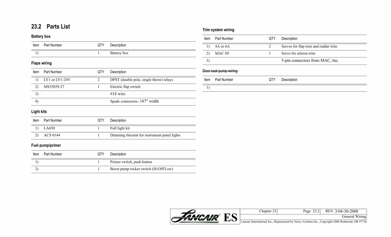
system wiring
Part Number QTY Description
4A or 6A 2 Servos for flap trim and rudder trim
MAC S9 1 Servo for aileron trim
5-pin connectors from MAC, Inc.
seal pump wiring
Part Number QTY Description
3/04-30-2008
23.2 Parts List Battery box
Item Part Number QTY Description
1) 1 Battery box
Flaps wiring
Item Part Number QTY Description
1) LY1 or LY1-24V 2 DPST (double pole, single throw) relays
2) MS35059-27 1 Electric flap switch
3) #18 wire
4) Spade connectors-.187" width
Light kits
Item Part Number QTY Description
1) LA650 1 Full light kit
2) ACS 0144 1 Dimming rheostat for instrument panel lights
Fuel pump/primer
Item Part Number QTY Description
1) 1 Primer switch, push button
2) 1 Boost pump rocker switch (Hi/Off/Low)
Trim
Item
1)
2)
3)
Door
Item
1)

Lancair International Inc., Represented by Neico Aviation Inc., Copyright 2008 Redmond, OR 97756
Chapter 23 Page 23.3 REV. 2nd Ed./08-15-2006General WiringES
23.3 Construction Procedures23.3.A Using the Wire Sizes DiagramThe wiring diagrams of this chapter do not include wire sizes. Wire sizes are determined from the wire size diagram.The wire size depends on load, length and voltage. As an example:
• 14 feet installation• 28V source• 20 ampere draw
Find the wire size.Answer: Find the number 14 under 28 volts source column. Follow the horizontal line to the right until intersects the slant 20-ampere line. At this point drop to the bottom of the chart. The value falls between No. 16 and No. 14, select the larger size, No. 14.The wire will be placed in conduit, so curve 1 applies. The maximum continuous current for No. 14 wire is 17 amperes.Note: Use aircraft-quality wire. When selecting the proper wire, consider all requirements such as operating temperatures and environmental conditions
Figure 23.3.A.1 Wire sizes diagram

Lancair International Inc., Represented by Neico Aviation Inc., Copyright 2008 Redmond, OR 97756
Chapter 23 Page 23.4 REV. 2nd Ed./08-15-2006General WiringES
unted on the aft side of FS 185 bulkhead
23.3.B Battery Box OptionsThe standard battery location for the Continental IO-550 powered Lancair ES is behind the FS 185 bulkhead or slightly in front of the bulkhead.There are many different options for installing the battery. Whatever method you decide to use, be sure you build a sturdy box with a strong battery retainer. Remember, that 25 lb.+ battery must be held in place when you're riding out some teeth-jarring turbulence. The following drawings show only two possible battery mounting methods. Snowline Welding produces a neat battery box that will mount quickly to the bulkhead (or firewall). Or you can build a battery box from scrap prepreg.WARNING: Check the CG of the aircraft prior to installation. The battery may need to install forward of the FS 185 bulkhead.Figure 23.3.B.1 Pre-built battery box mo

Lancair International Inc., Represented by Neico Aviation Inc., Copyright 2008 Redmond, OR 97756
Chapter 23 Page 23.5 REV. 2nd Ed./08-15-2006General WiringES
Figure 23.3.B.2 Installed battery box behind the FS 185 bulkhead
Battery box
FS 185 bulkhead

Lancair International Inc., Represented by Neico Aviation Inc., Copyright 2008 Redmond, OR 97756
Chapter 23 Page 23.6 REV. 2nd Ed./08-15-2006General WiringES
shown adjacent to the mbol is the breaker size. This will vary from yours for correct breaker
eakers
Autopilot 5 amps
HSI 5 amps
T&B 1 amp
Cabin fan 2 amps
Fuel quantity 3 amps
EGT/CHT/Fuel flow 2 amps
Tach. 5 amps
Oil temp./pressure 5 amps
Table 2: Misc. electrical circuit breakers
System Breaker
Fuel pump 7.5 amps
Starter 5 amps
Alt. field 5 amps
Trim systems 5 amps
Door seal pump 5 amps
Flaps 5 amps
Pitot heat 10 amps
Alternator 60 amps
Table 1: Avionics circuit breakers
Avionics system Breaker
grounded to the battery. For the Continental IO-550 engine option the battery should be mounted behind the FS 185 bulkhead as shown in Figure 23.3.C.1. This location requires that large cable (2 gauge) be routed all the way to the engine, which is heavy but unfortunately necessary.Note: Previously, with the IO-360 engine option, the battery was shown ahead of the firewall in the basic wiring schematic.
Circuit BreakersMore and more circuit breakers are being incorporated into the modern electrical system. You'll notice in most of the
Headphones 1 amp
Speaker 3 amps
Com 1 10 amps
Com 2 10 amps
GPS 3 amps
DME 3 amps
Transponder/Enc. 5 amps
Stormscope 5 amps
23.3.C Basic Wiring TechniquesThis section concentrates on the wiring necessary for starting the engine and getting power into the cockpit. Battery power must be channeled directly into the engine starter while the magnetos are "hot". After the engine has started, the alternator can both recharge the battery and provide a constant source of power to the cockpit mounted "buses", which are nothing more than strips of copper providing a positive (+) connection to a row of circuit breakers. You will usually have a bus for a row of avionics circuit breakers, and a separate bus (or buses) for the rest of the circuit breakers.In the remaining sections of this chapter, we will show wiring of different systems from the bus (+) to the ground (-), thus completing each circuit.
GroundingSince this is a composite airframe, you don't have the luxury of grounding to a convenient aluminum surface. You must bring a few ground posts into the cockpit, then terminate all your circuits to one of these posts. Although only one cockpit ground post is shown in the following schematic, it is a good idea to have several. You may even want to install one underneath the aft seat for the flap motor and power pack for the strobe lights. Ahead of the firewall, circuits are usually grounded to one of the engine bolts, which is in turn
wiring diagrams, a breaker symbol ismaster bus bar. The number in the syHere is a typical list of breaker sizes.system to system so be sure to check sizes.
Lighting circuit breakers
Lights Breaker
Cabin 5 amps
Instrument 5 amps
Landing 10 amps
Nav. 10 amps
Strobe 10 amps
Table 1: Avionics circuit br
Avionics system Breaker
Intercom 1 amp

Lancair International Inc., Represented by Neico Aviation Inc., Copyright 2008 Redmond, OR 97756
Chapter 23 Page 23.7 REV. 2nd Ed./08-15-2006General WiringES
Figure 23.3.C.1 Basic wiring schematic

Lancair International Inc., Represented by Neico Aviation Inc., Copyright 2008 Redmond, OR 97756
Chapter 23 Page 23.8 REV. 2nd Ed./08-15-2006General WiringES
Ground power
Master
Avionics
Starter
Figure 23.3.C.2 Overview of the forward side of the firewall wiring
Ground
Avionics bus
Main bus
Battery in
Dual alternator regulators
Lancair International Inc., Represented by Neico Aviation Inc., Copyright 2008 Redmond, OR 97756
Chapter 23 Page 23.9 REV. 2nd Ed./08-15-2006General WiringES
atic
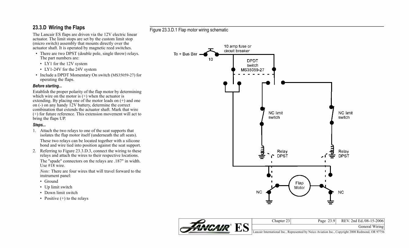
23.3.D Wiring the FlapsThe Lancair ES flaps are driven via the 12V electric linear actuator. The limit stops are set by the custom limit stop (micro switch) assembly that mounts directly over the actuator shaft. It is operated by magnetic reed switches.• There are two DPST (double pole, single throw) relays. The part numbers are:• LY1 for the 12V system• LY1-24V for the 24V system
• Include a DPDT Momentary On switch (MS35059-27) for operating the flaps.
Before starting...Establish the proper polarity of the flap motor by determining which wire on the motor is (+) when the actuator is extending. By placing one of the motor leads on (+) and one on (-) on any handy 12V battery, determine the correct combination that extends the actuator shaft. Mark that wire (+) for future reference. This extension movement will act to bring the flaps UP.Steps...1. Attach the two relays to one of the seat supports that
isolates the flap motor itself (underneath the aft seats).These two relays can be located together with a silicone bond and wire tied into position against the seat support.
2. Referring to Figure 23.3.D.3, connect the wiring to these relays and attach the wires to their respective locations.The "spade" connectors on the relays are .187" in width. Use #18 wire.Note: There are four wires that will travel forward to the instrument panel:• Ground• Up limit switch• Down limit switch• Positive (+) to the relays
Figure 23.3.D.1 Flap motor wiring schem

Lancair International Inc., Represented by Neico Aviation Inc., Copyright 2008 Redmond, OR 97756
Chapter 23 Page 23.10 REV. 2nd Ed./08-15-2006General WiringES
3. Secure the wires so that they cannot possibly get tangled with any of the flap actuator movements.
4. Attach the limit switch assembly to the actuator shaft.The final position will be determined later, but for now just put the magnetic reed switches on opposite ends of the base bracket, though not all the way to the ends. The limit switch that is at the far end of the shaft (away from the motor) is the one that will limit the flaps UP position.
5. For this discussion let's pick relay #2 as the one to be used for flaps UP. The other relay will be used for flaps DOWN. With this established, in Figure 23.3.D.3 the wire marked "To #2 Limit Switch” on relay #2 is connected to that limit switch. Also, the wire on flap relay #2 that is labeled "to motor" must be connected to the flap motor wire which was earlier labeled (+).Now we have the motor turning in the correct direction for flaps UP and the motor will be stopped by the correct magnetic reed switch (or limit switch).
Figure 23.3.D.2 Flap relay schematic
Figure 23.3.D.3 Flap relays

Lancair International Inc., Represented by Neico Aviation Inc., Copyright 2008 Redmond, OR 97756
Chapter 23 Page 23.11 REV. 2nd Ed./08-15-2006General WiringES
6. The flap control switch has two possible wires that could connect to the above limit switch #2. Refer to the drawing of a typical control switch in Figure 23.3.D.5. Either wire can be used on limit switch #2. This will determine which way the flap control switch moves to extend the flaps. Naturally, you want the movement on the control switch to be either "downward" or "aft" when dropping flaps. If the direction ends up being opposite, just turn the switch around in its instrument panel mounting hole.
7. The magnetic reed switch will have three possible contact points. Use the center contact and ONLY the contact labelled "W".
Testing the Flap Wiring SystemAfter completing all the wiring, test run the system and check for the following two items:
• The limit switches must stop the travel in their respective directions.
• The flap motor must be self braking. That is, when you release the control switch, the motor should stop quickly instead of gliding or coasting for two or three seconds. Such coasting is not acceptable and will not occur if everything is wired correctly.
Figure 23.3.D.4 Flap reed switch

Lancair International Inc., Represented by Neico Aviation Inc., Copyright 2008 Redmond, OR 97756
Chapter 23 Page 23.12 REV. 2nd Ed./08-15-2006General WiringES
Setting the Flap Limit Stops
Steps...1. To adjust the DOWN limit stop, run the flaps to the
proper down limit position of 40 degrees. Simply “zero” the smart level in the “up” position. As the flap travels it will read the actual flap setting.
2. When it is adjusted properly, check the following:• The limit stop screws are snug, and• that the hex nut that secures the clevis onto the flap
motor is also tight against the clevis.3. Install the limit stop assembly dust cover over this
installation by wire tieing the cover in place. Use a couple of dabs of silicone to help secure it in position.
Figure 23.3.D.5 Flap wiring layout
Lancair International Inc., Represented by Neico Aviation Inc., Copyright 2008 Redmond, OR 97756
Chapter 23 Page 23.13 REV. 2nd Ed./08-15-2006General WiringES
ematic
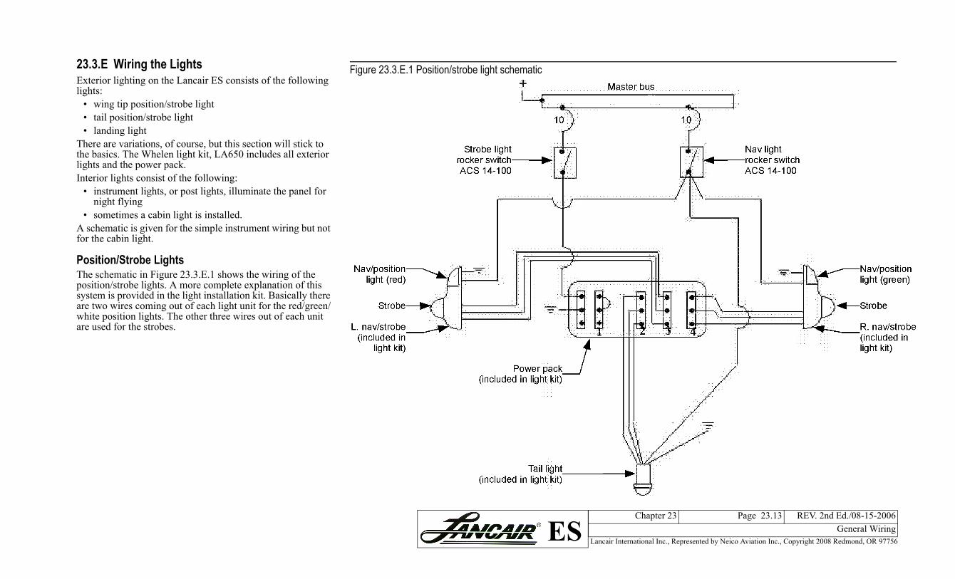
23.3.E Wiring the LightsExterior lighting on the Lancair ES consists of the following lights:• wing tip position/strobe light• tail position/strobe light• landing light
There are variations, of course, but this section will stick to the basics. The Whelen light kit, LA650 includes all exterior lights and the power pack.Interior lights consist of the following:
• instrument lights, or post lights, illuminate the panel for night flying
• sometimes a cabin light is installed.A schematic is given for the simple instrument wiring but not for the cabin light.
Position/Strobe LightsThe schematic in Figure 23.3.E.1 shows the wiring of the position/strobe lights. A more complete explanation of this system is provided in the light installation kit. Basically there are two wires coming out of each light unit for the red/green/white position lights. The other three wires out of each unit are used for the strobes.
Figure 23.3.E.1 Position/strobe light sch

Lancair International Inc., Represented by Neico Aviation Inc., Copyright 2008 Redmond, OR 97756
Chapter 23 Page 23.14 REV. 2nd Ed./08-15-2006General WiringES
Landing LightsThe typical landing light installation on the Lancair ES uses a G.E. 4509 bulb. This is an excellent light and is produced by a number of manufacturers. They can even be found in many auto parts stores.The cowling is an excellent location for the landing light, although this is likely to be argued among builders who want the light in their wings. We're not saying the wing location is not good, but you can avoid the following by locating the landing light in the cowling:
• cutting into the wing structure,• simplify the plastic lens, and • shorten the wire length by mounting it in the cowling.
Figure 23.3.E.2 Landing light wiring

Lancair International Inc., Represented by Neico Aviation Inc., Copyright 2008 Redmond, OR 97756
Chapter 23 Page 23.15 REV. 2nd Ed./08-15-2006General WiringES
matic
Instrument LightingThere are an increasing number of instrument lighting methods. The old standby postlights that were mounted adjacent to every instrument are giving way to internally lit instruments and lighted instrument covers. Whichever method you choose, most likely they will be wired similar to the following schematic.Figure 23.3.E.3 Instrument lighting sche
Lancair International Inc., Represented by Neico Aviation Inc., Copyright 2008 Redmond, OR 97756
Chapter 23 Page 23.16 REV. 2nd Ed./08-15-2006General WiringES
schematic
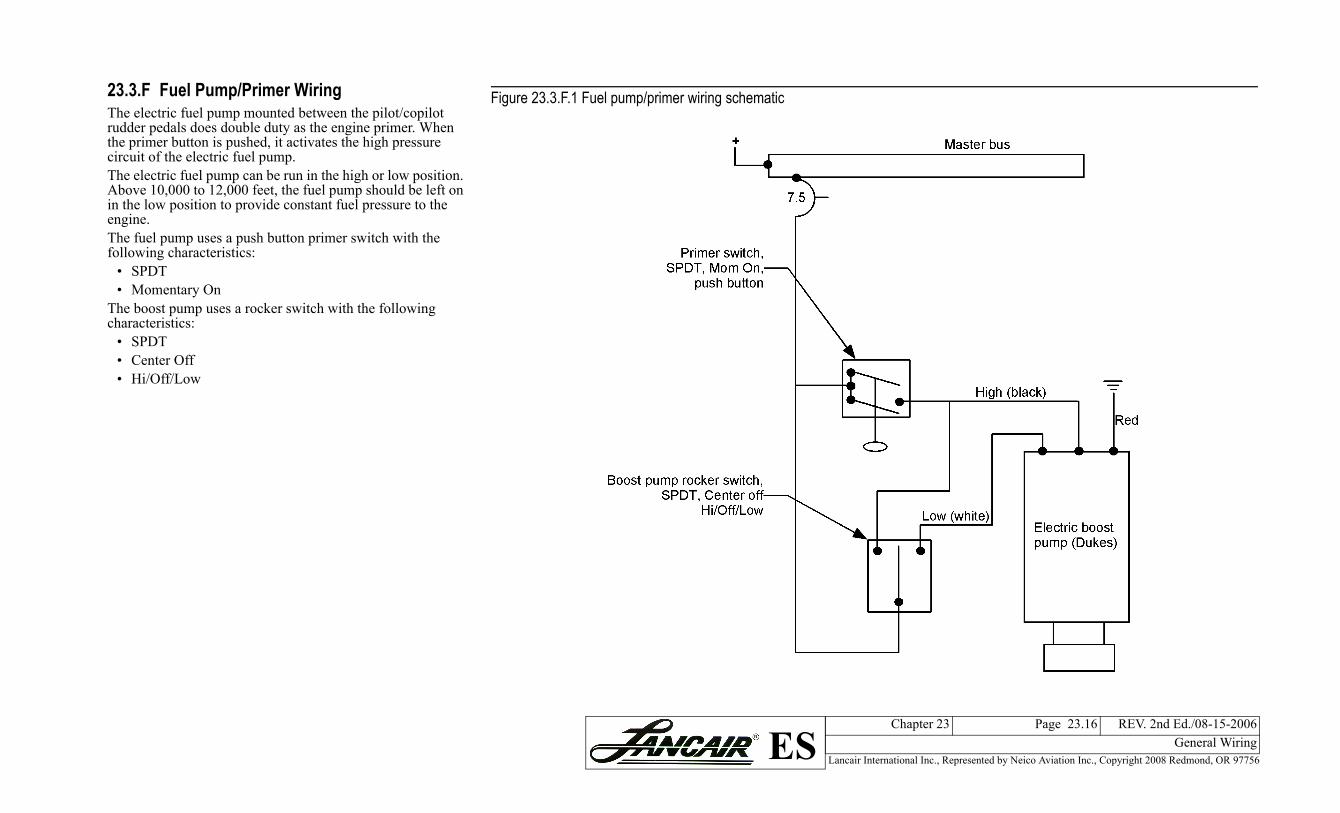
23.3.F Fuel Pump/Primer WiringThe electric fuel pump mounted between the pilot/copilot rudder pedals does double duty as the engine primer. When the primer button is pushed, it activates the high pressure circuit of the electric fuel pump.The electric fuel pump can be run in the high or low position. Above 10,000 to 12,000 feet, the fuel pump should be left on in the low position to provide constant fuel pressure to the engine. The fuel pump uses a push button primer switch with the following characteristics:• SPDT• Momentary On
The boost pump uses a rocker switch with the following characteristics:
• SPDT• Center Off• Hi/Off/Low
Figure 23.3.F.1 Fuel pump/primer wiring

Lancair International Inc., Represented by Neico Aviation Inc., Copyright 2008 Redmond, OR 97756
Chapter 23 Page 23.17 REV. 2nd Ed./08-15-2006General WiringES
routing
23.3.G Trim System WiringWiring instructions are included with your trim systems. The following diagrams provide suggestions on wire routing and plug locations so you can remove only the servo by simply unplugging it. You can also remove the entire control surface by unplugging the servo outside the surface.This section includes wiring for the following:• Elevator trim• Aileron trim• Rudder trim
For wiring the five-wire servos for the elevator trim and the rudder trim, either 4A or 6A, an excellent 5-pin connector plug is available from MAC Inc. (The plug actually has six pins so just don't use one). MAC Inc. also sells a color coordinated five-wire harness which is easier to install than stringing five individual wires.
Figure 23.3.G.1 Elevator trim servo wire

Lancair International Inc., Represented by Neico Aviation Inc., Copyright 2008 Redmond, OR 97756
Chapter 23 Page 23.18 REV. 2nd Ed./08-15-2006General WiringES
re 23.3.G.3 Rudder trim servo wire routing
For wiring the S9 aileron servo (two wires), you can use an AMP connector available at electronic supply stores.Both of the wires coming out of the servo are white. Don’t worry which one is connected to (+) or (-) because the servo direction is reversed by switching polarity. When the system is completely wired, check that the trim tab switch moves the servo in the correct direction. If it doesn’t, simply rotate the switch 180 degrees or switch the wires at one of the plugs.Figure 23.3.G.2 Aileron trim servo wire routing
Figu

Lancair International Inc., Represented by Neico Aviation Inc., Copyright 2008 Redmond, OR 97756
Chapter 23 Page 23.19 REV. 2nd Ed./08-15-2006General WiringES
3/04-30-2008
23.3.H Wiring the Automatic Door Seal PumpOne option on the Lancair ES is an automatic door seal pump. With this system, you can inflate the door seal with a flip of a switch, and the seal will remain at a constant 20 psi. When you are ready to open the door, flip the switch again and the seal deflates.The inflatable door seal is kept at 20 psi by a remotely mounted air pump. In this system, a pressure switch activates the pump when the seal pressure falls below 20 psi. When the pump is turned off, the pressure in the door seal will vent out through the panel mounted on/off switch. The check valve (4LD-061-D00) prevents the pressure from bleeding off through the pump.Wiring for the door seal pump and pressure switch is very basic. For additional information regarding the installation of the door seal, refer to Chapter 6, 6.3.J Installing the Door Seal on page 6.19.
Figure 23.3.H.1 Door seal pump wiring