ERT 208 REACTION ENGINEERINGportal.unimap.edu.my/portal/page/portal30/Lecturer Note… · ·...
49
ERT 208 REACTION ENGINEERING MISMISURAYA MEOR AHMAD School of bioprocess engineering Unimap CONVERSION & REACTOR SIZING (part 2)
Transcript of ERT 208 REACTION ENGINEERINGportal.unimap.edu.my/portal/page/portal30/Lecturer Note… · ·...

ERT 208
REACTION ENGINEERING
MISMISURAYA MEOR AHMAD School of bioprocess engineering
Unimap
CONVERSION & REACTOR SIZING (part 2)

REACTORS IN
SERIES

objectives DEFINE conversion and REWRITE all the balance equation in term of conversion EVALUATE the size of CSTR & PFR based on conversion, DETERMINE the reactor volume necessary to achieved a specified conversion, COMPARE CSTRs & PFRs and overall conversion for reactor arranged in series. IDENTIFY the best arrangement of reactors in series.

• Reactors are connected in series so that the
exit stream of one reactor is the feed stream for another reactor.
• Therefore, conversion is defined in terms
of location at a point downstream rather than with respect to any single reactor.

• So that Conversion, X is the total number of
moles of A that have reacted up to that point per
mole of A fed to the first reactor.
• For reactors in series,

• But, the definition of conversion can only be used when the feed stream only enters the first reactor in the series &
no side streams either fed or withdrawn.
• The molar flow rate of A at point i = moles of A
fed to the first reactor minus all moles of A
reacted up to point i.

• For example:
• X1 at point i=1 is the conversion achieved in the PFR.
• X2 at point i=2 is the total conversion achieved at this point in PFR and CSTR.
• X3 at point i=3 is the total conversion achieved by all three reactors (PFR, CSTR & PFR).

Consider 3 different schemes of reactors in series:
1) Two CSTRs
2) Two PFRs
3) Combination of PFRs & CSTRs
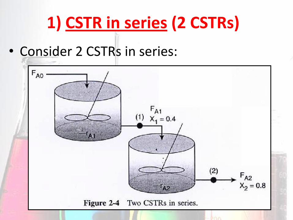
1) CSTR in series (2 CSTRs)
• Consider 2 CSTRs in series:

So that
The rate of disappearance of A is –rA1 at conversion X1.
A mole balance on reactor 1 gives:
The molar flow rate of A at points 1 is:
Equation 1
Equation 2
# Combining Equation 1 & 2 then rearrange,

So that
The rate of disappearance of A, –rA2 is evaluated at the
conversion of the exit stream of reactor 2, X2.
A mole balance on reactor 2 gives:
The molar flow rate of A at points 2 is:
Equation 3
Equation 4
# Combining Equation 2, 3 & 4 then rearrange,
Used (X2–X1) to calculate V2 at X2.
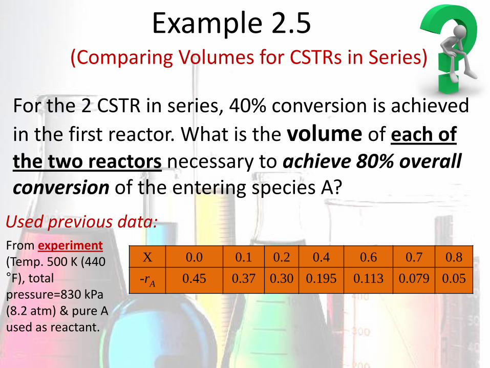
From experiment (Temp. 500 K (440 °F), total pressure=830 kPa (8.2 atm) & pure A used as reactant.
Used previous data:
X 0.0 0.1 0.2 0.4 0.6 0.7 0.8
-rA 0.45 0.37 0.30 0.195 0.113 0.079 0.05
For the 2 CSTR in series, 40% conversion is achieved
in the first reactor. What is the volume of each of the two reactors necessary to achieve 80% overall conversion of the entering species A?
Example 2.5 (Comparing Volumes for CSTRs in Series)

Answer Used previous data & calculated:
1st method

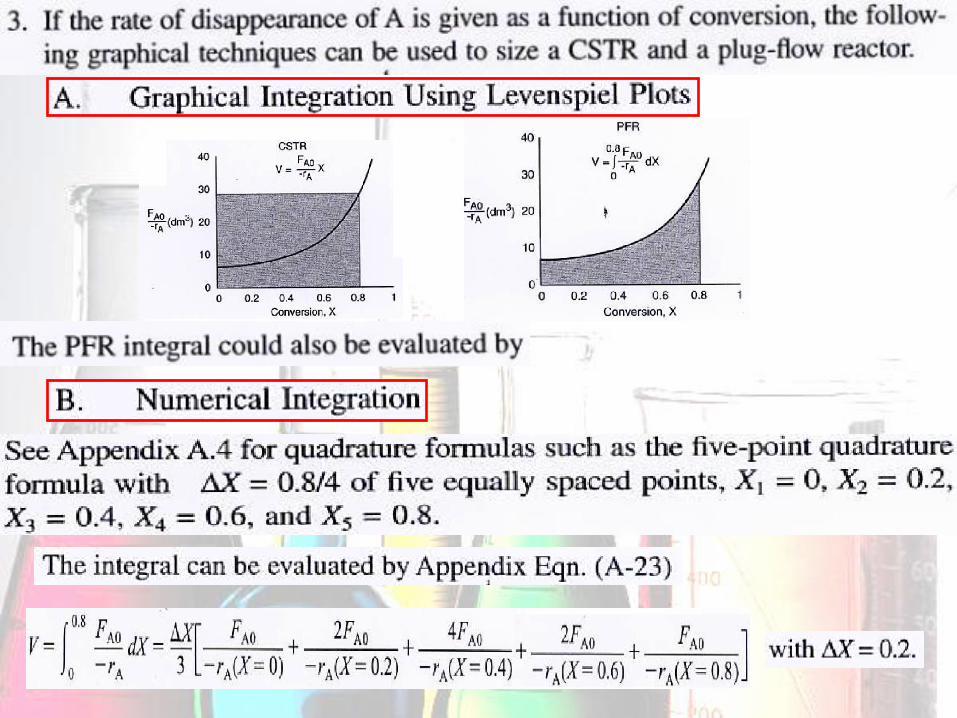
2nd method Shade the area for Levenspiel Plot

• For CSTRs in series, the rate –rA1 is evaluated at X1 = 0.4 and rate –rA2 is evaluated at X2 = 0.8.
Notice The sum of 2 CSTRs reactor volume in series (4020 dm3) < the volume of one CSTR (6400 dm3) to achieve the same conversion, 80%.
• The total volume for 2 reactors in series:
By comparison, the volume necessary to achieve 80% conversion in one CSTR (Example 2.2):

Model a large number of CSTRs in series = a PFR
Conclusion We can model a PFR with a large number of CSTRs in series. This concept of using many CSTRs in series to model a PFR will be used to model catalysts decay in Packed Bed Reator/ transient heat effect in PFRs.
We want to compare the Total Volume of all the CSTRs with the volume of one PFR for the same conversion, 80%.

2) PFRs in series (2 PFRs)
• Consider 2 CSTRs in series:

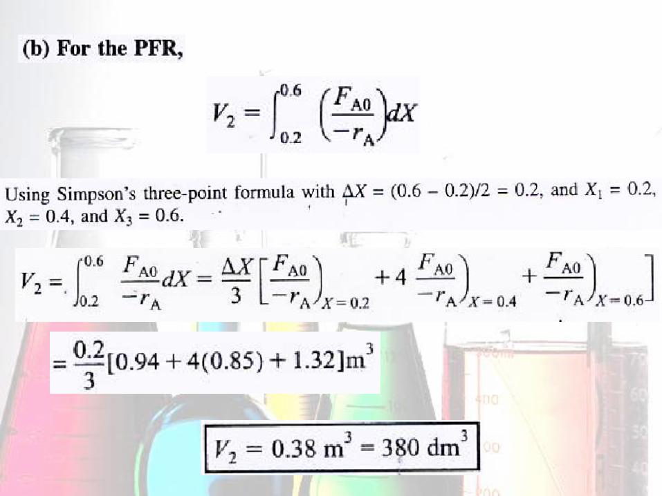
The equation for two PFR in series:
Total reactor volume for 2 PFR in series = Reactor volume for one PFR
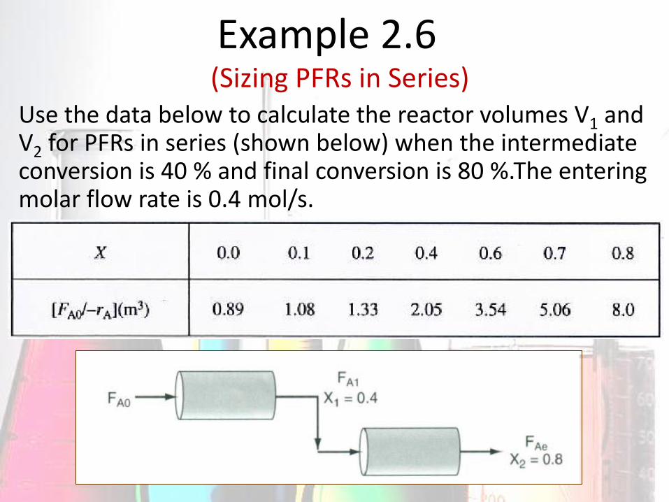
Use the data below to calculate the reactor volumes V1 and
V2 for PFRs in series (shown below) when the intermediate conversion is 40 % and final conversion is 80 %.The entering molar flow rate is 0.4 mol/s.
Example 2.6 (Sizing PFRs in Series)

Use the simpson’s three point rule:
Answer 1st method
There are 2 method to solve PFR: 1) Use the Simpson’s rule
2) Shade the area for Levenspiel Plot

Note: This volume same with a single PFR to achieve 80 % conversion in Example 2-4

3) Combinations of CSTRs and PFRs in Series
• Consider the dimerization reaction of propylene into isohexanes.
The Industrial reactors to dimerize propylene into isohexanes (2 CSTRs & one PFR in series)
A schematic of the industrial reactor system

Assume the reaction carried out in this reactor follows ‘ curve given by Table 2-3
The volume of the first two CSTRs in series are (Example 2-5):
1st method

2nd method: (Shade the area for Levenspiel Plot)

Example 2.7
The isomerization of butane was done adiabatically in liquid phase and the data below are obtained.
(An Adiabatic Liquid Phase Isomerization)
Calculate the volume of each reactors for an entering molar flow rate of n-butane of 50 kmol/hr.

Answer
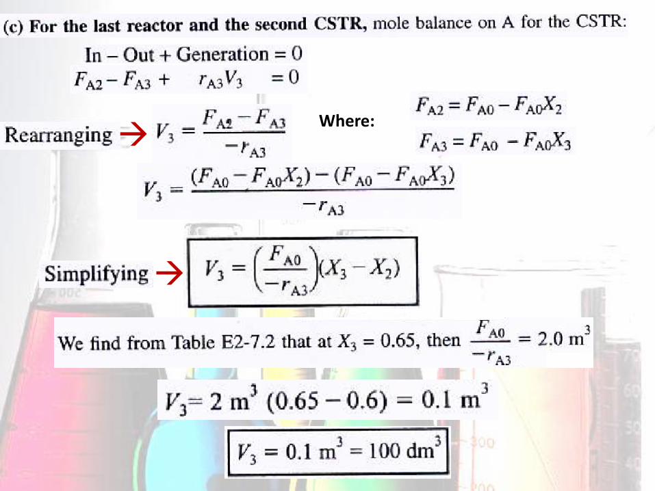
Where:

Comparing the CSTR & PFR reactor volumes & reactor sequencing
Based on the graph: (Usually for adiabatic reaction)
1) The area under the curve between X = 0 and X = 0.2 PFR Area > Rectangular Area (CSTR)
2) The area under the curve between X = 0.6 and X = 0.65
Rectangular Area (CSTR) > PFR Area

Which reactor should go first to give the highest overall conversion?
It depends on:
1) the shape of Levenspiel plots (FAO/-rA) versus X
2) The relative reactor sizes

Methods:
Suppose a Levenspiel plot (FAO/-rA) versus X will be given for three reactors volumes in series VCSTR1 = 3 m3, VCSTR2 = 2 m3 & VPFR = 1.2 m3. Then find the highest possible CONVERSION, X
The methods we used to calculate reactor volumes all apply, except the procedure is reversed & a trial-and-error solution is needed to find the exit overall conversion from each reactor.
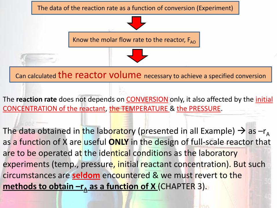
The data of the reaction rate as a function of conversion (Experiment)
Know the molar flow rate to the reactor, FAO
Can calculated the reactor volume necessary to achieve a specified conversion
The reaction rate does not depends on CONVERSION only, it also affected by the initial CONCENTRATION of the reactant, the TEMPERATURE & the PRESSURE.
The data obtained in the laboratory (presented in all Example) as –rA as a function of X are useful ONLY in the design of full-scale reactor that are to be operated at the identical conditions as the laboratory experiments (temp., pressure, initial reactant concentration). But such circumstances are seldom encountered & we must revert to the methods to obtain –rA as a function of X (CHAPTER 3).
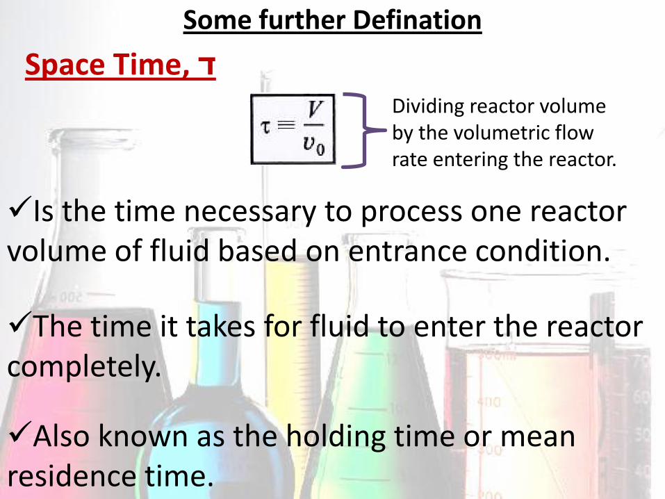
Some further Defination
Space Time, ד
Is the time necessary to process one reactor volume of fluid based on entrance condition.
The time it takes for fluid to enter the reactor completely.
Dividing reactor volume by the volumetric flow rate entering the reactor.
Also known as the holding time or mean residence time.

For Example, consider the tubular reactor 20 m long & 0.2 m3 in volume.
If the volumetric flow rate were 0.01 m3/s, so that:
Means that, it would take 20 s for the fluid at point a to move to point b, which corresponds to a space time of 20 s.

Table 2-4 show a range of typical processing time in term of the space time for industrial reactor.


Space Velocity, SV
SV as the reciprocal of the space time
The 2 space velocities commonly used in industry are:
1) Liquid-hourly space velocity
2) Gas-hourly space velocity

Example 2.8 (Reactor Space Times & space Velocities)
Answer
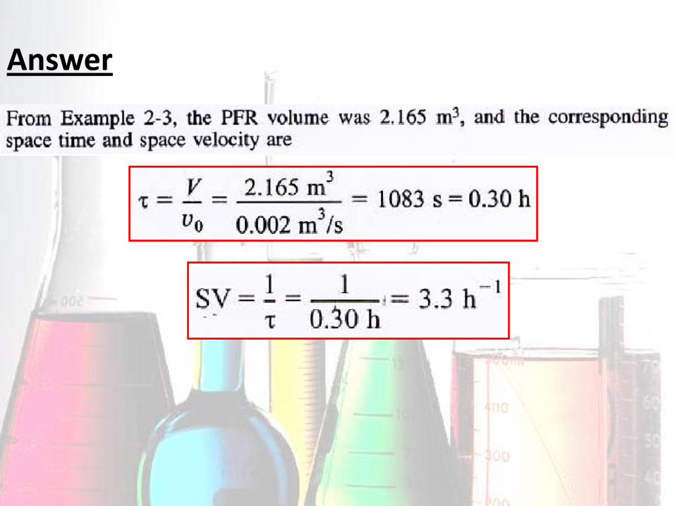
Answer
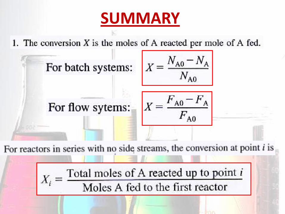
SUMMARY


Let’s think
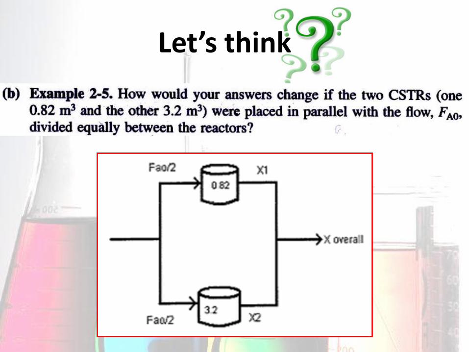
Let’s think

Let’s think

Let’s think

Q &A
THANK YOU