Error Patterns in Belief Propagation Decoding of Polar...
5
Error Patterns in Belief Propagation Decoding of Polar Codes and Their Mitigation Methods Shuanghong Sun, Sung-Gun Cho, and Zhengya Zhang Department of Electrical Engineering and Computer Science University of Michigan, Ann Arbor, MI, 48109-2122 Abstract—Belief propagation (BP) is a high-throughput decod- ing algorithm for polar codes, but it is known to underperform successive cancellation (SC) decoding and list decoding in error- correcting performance. In this work, we study the error patterns of BP decoding of polar codes to uncover the error mechanisms, as well as the influence of channel condition, code design, and decoder implementation. Based on the insights, we design new ways to detect, prevent and overcome BP decoding errors. I. I NTRODUCTION Polar codes are the first provably capacity-achieving error- correcting codes for any binary-input discrete memoryless channels (B-DMC) [1], and the error-correcting capability of polar code holds high promise. The two main decoding algorithms are successive cancellation (SC) [1] and belief propagation (BP) [2]. SC exhibits a better error-correcting performance than BP [3], and list decoding [4], viewed as an enhanced SC, further improves the performance but with an increased complexity. BP on the other hand, provides a higher throughput and a reduced latency, but it sacrifices error- correcting performance. BP is an iterative message passing algorithm operating on a factor graph. The same BP decoding algorithm has been widely used in decoding low-density parity-check (LDPC) codes. Despite the impressive performance seen in decoding LDPC codes, BP has shown a weakness known as the error floor phenomenon [5]. Error floors occur at moderate to high SNR levels, preventing the waterfall-like improvement in error rate with increasing SNR. In the error floor region, decoding errors are dominated by a small number of fixed patterns known as trapping sets [5]. In this work, we analyze the error patterns in the BP decoding of polar codes. The decoding errors are classified and the factors affecting decoding, including channel SNR, code design, decoding algorithm, and implementation, are analyzed. Based on the insights, we provide preliminary ideas of how the decoding errors can be mitigated. II. BACKGROUND A polar code of block length N =2 n has a generator matrix G that is the n-th Kronecker power of matrix F = 10 11 , i.e., G N = F ⊗n [1]. Fig. 1 is the factor graph of an N =8 polar code, where the plus sign represents XOR, and the equal sign represents pass-through. To encode, a message u is placed on the left side of the factor graph, and the codeword x = uG is obtained on the right side. The subchannel seen by each bit + = + = + = + = + = + = + = + = + = + = + = + = (0,0) (0,1) (0,2) (0,3) (0,4) (0,5) (0,6) (0,7) (1,0) (1,1) (1,2) (1,3) (1,4) (1,5) (1,6) (1,7) (2,0) (2,1) (2,2) (2,3) (2,4) (2,5) (2,6) (2,7) (3,0) (3,1) (3,2) (3,3) (3,4) (3,5) (3,6) (3,7) Fig. 1. Factor graph of N=8 polar code. exhibits a polarization phenomenon when the code length is sufficiently long and decoded using the SC algorithm. Reliable bits are used to transmit information, and the unreliable ones are fixed to known values, normally 0. The frozen set A denotes the set of unreliable bits [1]. In SC decoding, the message bits ˆ u 0 to ˆ u N-1 are obtained one bit after another based on the channel output y and the previously decoded bits. If i ∈A, ˆ u i =0; otherwise ˆ u i is decoded by the maximum likelihood decision rule: ˆ u i = ( 0 if P (y, ˆ u i-1 0 |ui=0) P (y, ˆ u i-1 0 |ui=1) > 1 1 otherwise where P (y, ˆ u i-1 0 |u i = b) refers to the probability that the received vector is y and the previously decoded bits being ˆ u 0 through ˆ u i-1 , given the current bit being b, where b ∈{0, 1} [6]. The SC decoding latency is O(N ). BP decoding operates message passing on the factor graph. Frozen set information is propagated from left to right on the factor graph, and channel output y is propagated from right to left. The estimated message ˆ u is obtained on the left side. The decoding accuracy can be improved by running more iterations. The BP decoding latency is O(log N ). III. ERROR CLASSIFICATION To understand how decoding fails, we obtain hard decisions ˆ u at the end of each BP decoding iteration. Due to the lack of a definitive convergence check in polar decoding, we use hard decisions from consecutive iterations to decide whether decoding has converged. If hard decisions over consecutive iterations agree, we consider it has converged. 1199 978-1-5386-3954-2/16/$31.00 ©2016 IEEE Asilomar 2016
Transcript of Error Patterns in Belief Propagation Decoding of Polar...

Error Patterns in Belief Propagation Decoding ofPolar Codes and Their Mitigation Methods
Shuanghong Sun, Sung-Gun Cho, and Zhengya ZhangDepartment of Electrical Engineering and Computer Science
University of Michigan, Ann Arbor, MI, 48109-2122
Abstract—Belief propagation (BP) is a high-throughput decod-ing algorithm for polar codes, but it is known to underperformsuccessive cancellation (SC) decoding and list decoding in error-correcting performance. In this work, we study the error patternsof BP decoding of polar codes to uncover the error mechanisms,as well as the influence of channel condition, code design, anddecoder implementation. Based on the insights, we design newways to detect, prevent and overcome BP decoding errors.
I. INTRODUCTION
Polar codes are the first provably capacity-achieving error-correcting codes for any binary-input discrete memorylesschannels (B-DMC) [1], and the error-correcting capabilityof polar code holds high promise. The two main decodingalgorithms are successive cancellation (SC) [1] and beliefpropagation (BP) [2]. SC exhibits a better error-correctingperformance than BP [3], and list decoding [4], viewed asan enhanced SC, further improves the performance but withan increased complexity. BP on the other hand, provides ahigher throughput and a reduced latency, but it sacrifices error-correcting performance.
BP is an iterative message passing algorithm operating ona factor graph. The same BP decoding algorithm has beenwidely used in decoding low-density parity-check (LDPC)codes. Despite the impressive performance seen in decodingLDPC codes, BP has shown a weakness known as the errorfloor phenomenon [5]. Error floors occur at moderate to highSNR levels, preventing the waterfall-like improvement in errorrate with increasing SNR. In the error floor region, decodingerrors are dominated by a small number of fixed patternsknown as trapping sets [5].
In this work, we analyze the error patterns in the BPdecoding of polar codes. The decoding errors are classified andthe factors affecting decoding, including channel SNR, codedesign, decoding algorithm, and implementation, are analyzed.Based on the insights, we provide preliminary ideas of howthe decoding errors can be mitigated.
II. BACKGROUND
A polar code of block length N = 2n has a generator matrixG that is the n-th Kronecker power of matrix F =
[1 01 1
], i.e.,
GN = F⊗n [1]. Fig. 1 is the factor graph of an N = 8 polarcode, where the plus sign represents XOR, and the equal signrepresents pass-through. To encode, a message u is placed onthe left side of the factor graph, and the codeword x = uG isobtained on the right side. The subchannel seen by each bit
+=+=+=+=
+=+=+=+=
+=+=+=+=
(0,0)
(0,1)
(0,2)
(0,3)
(0,4)
(0,5)
(0,6)
(0,7)
(1,0)
(1,1)
(1,2)
(1,3)
(1,4)
(1,5)
(1,6)
(1,7)
(2,0)
(2,1)
(2,2)
(2,3)
(2,4)
(2,5)
(2,6)
(2,7)
(3,0)
(3,1)
(3,2)
(3,3)
(3,4)
(3,5)
(3,6)
(3,7)
Fig. 1. Factor graph of N=8 polar code.
exhibits a polarization phenomenon when the code length issufficiently long and decoded using the SC algorithm. Reliablebits are used to transmit information, and the unreliable onesare fixed to known values, normally 0. The frozen set Adenotes the set of unreliable bits [1].
In SC decoding, the message bits u0 to ˆuN−1 are obtainedone bit after another based on the channel output y and thepreviously decoded bits. If i ∈ A, ui = 0; otherwise ui isdecoded by the maximum likelihood decision rule:
ui =
{0 if P (y,ui−1
0 |ui=0)
P (y,ui−10 |ui=1)
> 1
1 otherwise
where P (y, ui−10 |ui = b) refers to the probability that the
received vector is y and the previously decoded bits being u0
through ui−1, given the current bit being b, where b ∈ {0, 1}[6]. The SC decoding latency is O(N).
BP decoding operates message passing on the factor graph.Frozen set information is propagated from left to right on thefactor graph, and channel output y is propagated from right toleft. The estimated message u is obtained on the left side.The decoding accuracy can be improved by running moreiterations. The BP decoding latency is O(logN).
III. ERROR CLASSIFICATION
To understand how decoding fails, we obtain hard decisionsu at the end of each BP decoding iteration. Due to the lackof a definitive convergence check in polar decoding, we usehard decisions from consecutive iterations to decide whetherdecoding has converged. If hard decisions over consecutiveiterations agree, we consider it has converged.
1199978-1-5386-3954-2/16/$31.00 ©2016 IEEE Asilomar 2016
iteration 27
iteration 29 iteration 30
iteration 28
threshold threshold
threshold threshold
Fig. 2. Soft decisions of an unconverged error in BP decoding of a (256,128) code.
A. Unconverged Error
If hard decisions fail to agree within a maximum allowediteration limit, and there is no defined pattern of error, we callit an unconverged error. Unconverged errors are most commonat a low SNR level where the channel is noisy and the decoderis unable to resolve the errors.
Assume an all-zero codeword is transmitted using binaryphase-shift keying (BPSK) modulation; and a bit ui is decodedcorrectly if the soft decision of ui > 0 and incorrectlyotherwise. A plot of the soft decisions of u is shown in Fig. 2,illustrating an unconverged error for a (256, 128) code. Thedecision threshold is 0. The soft decisions keep flipping acrossthe decision threshold, and incorrect soft decisions hoveraround the decision threshold. There is no obvious pattern inthe decisions, and more iterations do not help to find correctconvergence.
B. Converged Error
As SNR increases, unconverged errors start to disappear,and errors of systematic patterns start to emerge. The ma-jority of systematic error patterns we found are attributed toconverging to wrong codewords, or falling to local minimaof BP decoding operating on loopy factor graphs. The factorgraphs of polar codes contain loops, so a flooding BP decoderis not immune to local minima problems.
If hard decisions are stable and agree over consecutiveiterations, but the decoded message is incorrect, i.e., u 6= u, wecall it a converged error. Converged errors are most commonat moderate to high SNR, and it usually takes only a smallnumber of iterations to reach a steady state, as illustrated inFig. 3 for a converged error in the decoding of a (256, 128)code. In this example, within two or three iterations, the softdecisions of a small number of bits are found to be trappedin wrong decisions, and they cannot be recovered using moreiterations.
The particular case illustrated in Fig. 3 represents a localminimum state in BP decoding. The few incorrect bits rein-force the wrong decisions among themselves through loops inthe factor graph, making it impossible to make any progresstowards convergence, which is similar to a trapping set foundin the BP decoding of LDPC codes.
iteration 1
iteration 3 iteration 4
iteration 2
threshold threshold
threshold threshold
Fig. 3. Soft decisions of a converged error in BP decoding of a (256, 128)code.
iteration 12
iteration 14 iteration 15
iteration 13
threshold threshold
threshold threshold
Fig. 4. Soft decisions of an oscillation error in BP decoding of a (256, 128)code.
C. Oscillation Error
Loops in the factor graph allow the propagation of incor-rect messages through BP decoding, causing oscillations. Asincorrect messages travel around a loop, the decisions also gothrough a round of changes.
If hard decisions are unstable and change periodically overiterations, we call it an oscillation error. Although an oscil-lation error is also an unconverged error, an oscillation errorfeatures a pronounced pattern of periodic changes. An exampleof the oscillation error is shown in Fig. 4. The illustratederror has an oscillation period of 2 iterations. A group ofbits are incorrect in iteration 12; the incorrect bits all turncorrect in iteration 13, but they turn incorrect again in iteration14. If decoding is terminated in iteration 13, decoding wouldbe done correctly. However, there is no way for the decoderto decide when to terminate in the absence of a definitiveconvergence detector in polar codes. Relying on checking harddecisions over consecutive iterations does not help terminatean oscillation error in the right iteration.
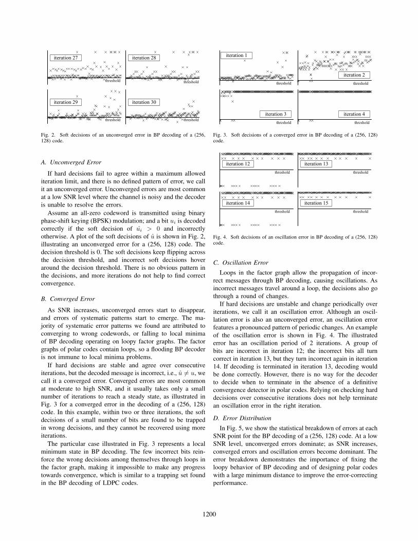
D. Error Distribution
In Fig. 5, we show the statistical breakdown of errors at eachSNR point for the BP decoding of a (256, 128) code. At a lowSNR level, unconverged errors dominate; as SNR increases,converged errors and oscillation errors become dominant. Theerror breakdown demonstrates the importance of fixing theloopy behavior of BP decoding and of designing polar codeswith a large minimum distance to improve the error-correctingperformance.
1200
3Eb/N0 (dB)
3.4 3.8 4.2 4.6 5 5.4 5.8 6.2 6.6 7 7.4
100%
80%
60%
40%
20%
0%
unconverged converged oscillation
3 3.4 3.8 4.2 4.6 5 5.4 5.8 6.2 6.6 7 7.4
SNR (dB)
unconverged steady oscillatory
Fig. 5. Error distribution for BP decoding of a (256, 128) code.
1E-10
1E-09
1E-08
1E-07
1E-06
1E-05
1E-04
1E-03
1E-02
1E-01
3 4 5 6 7
BER
/ F
ER
SNR (dB)
3Eb/N0 (dB)
4 5 6 7
10-1
10-3
10-5
10-7
10-9
Rc=0.5 FER
Rc=0.5 BER
Rc=0.53 FER
Rc=0.53 BER
3 3.4 3.8 4.2 4.6 5 5.4 5.8 6.2 6.6 7 7.4
SNR (dB)
unconverged steady oscillatoryFig. 6. Error distribution and error rate for BP decoding of a (256, 136) code.
IV. FACTORS AFFECTING DECODING
To gain an insight into decoding errors, we adjust codeand decoder design parameters and analyze the correspondingchanges in error rate and error breakdown.
A. Code Design
Take the rate-0.5 (256, 128) code in Fig. 5 as reference.We increase the rate of the 256-bit code from 0.5 to 0.53 andplot the error distribution and error rate of the rate-0.53 codein Fig. 6. The axes and markers of the distribution in Fig. 6are identical to those in Fig. 5, so they are omitted in Fig. 6for simplicity. All the later plots follow the same convention,unless they are explicitly marked.
The error rate of a higher rate code is worse as expected. Thenumber of converged errors at a high SNR level is noticeablyhigher. More converged errors can be explained by more freebits in a higher rate code resulting in more codewords, ora more crowded codeword space, making it more likely toconverge to a wrong codeword.
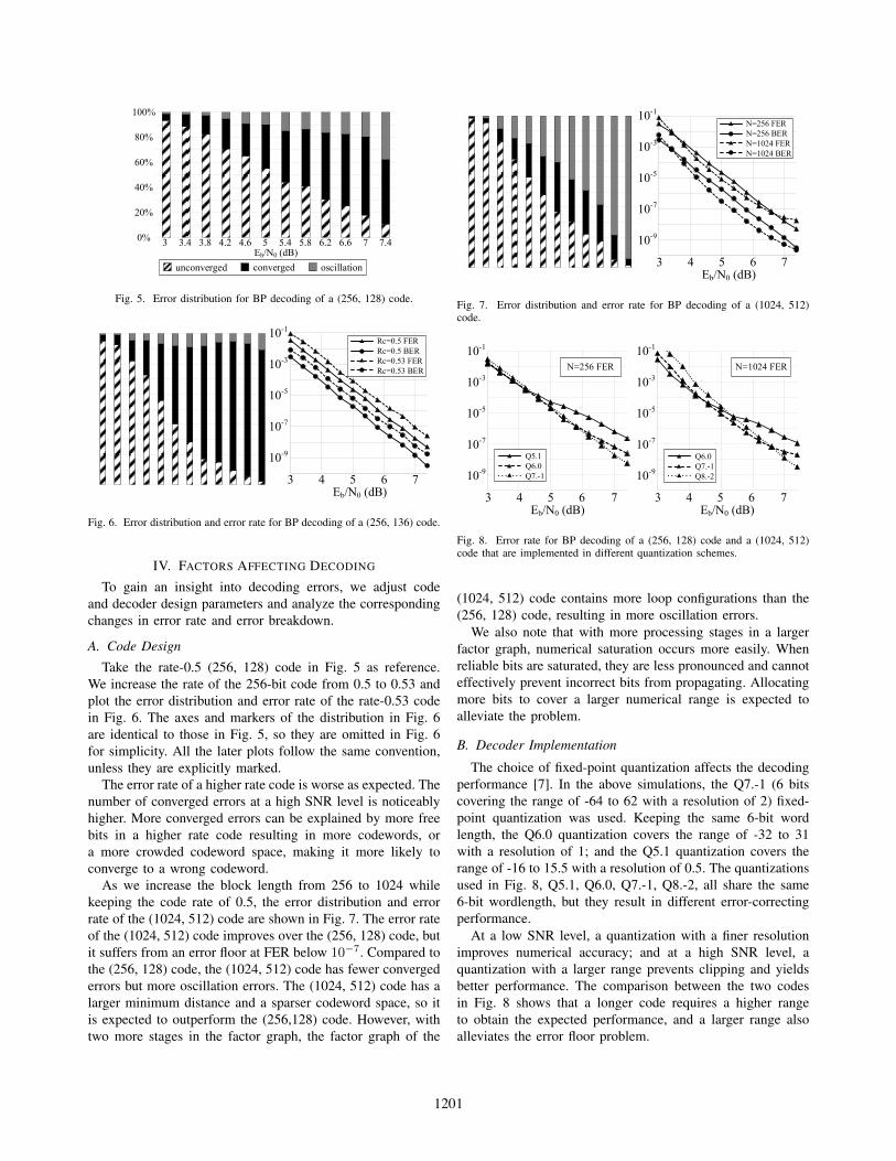
As we increase the block length from 256 to 1024 whilekeeping the code rate of 0.5, the error distribution and errorrate of the (1024, 512) code are shown in Fig. 7. The error rateof the (1024, 512) code improves over the (256, 128) code, butit suffers from an error floor at FER below 10−7. Compared tothe (256, 128) code, the (1024, 512) code has fewer convergederrors but more oscillation errors. The (1024, 512) code has alarger minimum distance and a sparser codeword space, so itis expected to outperform the (256,128) code. However, withtwo more stages in the factor graph, the factor graph of the
1E-10
1E-09
1E-08
1E-07
1E-06
1E-05
1E-04
1E-03
1E-02
1E-01
3 4 5 6 7
BER
/ F
ER
SNR (dB)3
Eb/N0 (dB)4 5 6 7
10-1
10-3
10-5
10-7
10-9
N=256 FER
N=256 BER
N=1024 FER
N=1024 BER
3 3.4 3.8 4.2 4.6 5 5.4 5.8 6.2 6.6 7 7.4
SNR (dB)
unconverged steady oscillatoryFig. 7. Error distribution and error rate for BP decoding of a (1024, 512)code.
1E-10
1E-09
1E-08
1E-07
1E-06
1E-05
1E-04
1E-03
1E-02
1E-01
3 4 5 6 7
FER
SNR (dB)3
Eb/N0 (dB)4 5 6 7
10-1
10-3
10-5
10-7
10-9
Q6.0
Q7.-1
Q8.-2
1E-10
1E-09
1E-08
1E-07
1E-06
1E-05
1E-04
1E-03
1E-02
1E-01
3 4 5 6 7
FER
SNR (dB)3
Eb/N0 (dB)4 5 6 7
10-1
10-3
10-5
10-7
10-9
Q5.1
Q6.0
Q7.-1
N=256 FER N=1024 FER
Fig. 8. Error rate for BP decoding of a (256, 128) code and a (1024, 512)code that are implemented in different quantization schemes.
(1024, 512) code contains more loop configurations than the(256, 128) code, resulting in more oscillation errors.
We also note that with more processing stages in a largerfactor graph, numerical saturation occurs more easily. Whenreliable bits are saturated, they are less pronounced and cannoteffectively prevent incorrect bits from propagating. Allocatingmore bits to cover a larger numerical range is expected toalleviate the problem.
B. Decoder Implementation
The choice of fixed-point quantization affects the decodingperformance [7]. In the above simulations, the Q7.-1 (6 bitscovering the range of -64 to 62 with a resolution of 2) fixed-point quantization was used. Keeping the same 6-bit wordlength, the Q6.0 quantization covers the range of -32 to 31with a resolution of 1; and the Q5.1 quantization covers therange of -16 to 15.5 with a resolution of 0.5. The quantizationsused in Fig. 8, Q5.1, Q6.0, Q7.-1, Q8.-2, all share the same6-bit wordlength, but they result in different error-correctingperformance.
At a low SNR level, a quantization with a finer resolutionimproves numerical accuracy; and at a high SNR level, aquantization with a larger range prevents clipping and yieldsbetter performance. The comparison between the two codesin Fig. 8 shows that a longer code requires a higher rangeto obtain the expected performance, and a larger range alsoalleviates the error floor problem.
1201
2 2.2 2.4 2.6 2.8 3 3.2 3.4 3.6SNR (dB)
unconverged steady oscillatory
2 2.2 2.4 2.6 2.8 3 3.2 3.4 3.6SNR (dB)
unconverged steady oscillatory
1E-05
1E-04
1E-03
1E-02
1E-01
1E+00
2 2.4 2.8 3.2 3.6
BE
R /
FE
R
SNR (dB)2
Eb/N0 (dB)2.4 2.8 3.2 3.6
100
10-1
10-2
10-3
10-5
w/o offset FER
w/ offset FER
without offset
correction
with offset
correction
2 2.2 2.4 2.6 2.8 3 3.2 3.4 3.6
10-4
w/o offset BER
w/ offset BER
Fig. 9. Error distribution and error rate for BP decoding of a (1024, 512)code at low SNR with and without offset correction.
CRC
encoder
CRC
decoder
polar
encoder
polar
decoderchannel
b0 = 0b1 = 0b2 = 0b3 = u0 b4 = 0b5 = u1 b6 = u2 b7 = u3
=b0 = 0b1 = c0 b2 = 0b3 = u0 b4 = 0b5 = u1 b6 = u2 b7 = u3
û0
ĉ0
û1
û2
û3
=
parity check result
Fig. 10. Illustration of concatenation of polar code with CRC.
Min-sum approximation is often applied to simplifyingthe log-likelihood ratio calculations. The associated min-sumapproximation error can be compensated by offset correction.Offset correction is especially effective at a low SNR level,as illustrated in Fig. 9. The number of unconverged errors isreduced, as offset correction reduces approximation errors andimproves the decoding performance.
V. ERROR DETECTION
As discussed above, a BP polar decoder is unaware ofwhether decoding has converged. An iteration-by-iterationhard decision check detects unconverged errors, but it failsto detect converged errors, which account for 20% to 90%of the errors. An iteration-by-iteration hard decision checkdetects oscillation errors, but it fails to find the right iterationto terminate decoding and stop oscillations. Therefore, we adda low-cost error detection scheme to catch the majority of theundetected errors.
The error detection scheme is based on concatenating polarcode with cyclic redundancy check (CRC) that consumes onlya small number of parity bits but provides a good detectioncapability. A CRC codec is added outside the polar codec,illustrated in Fig. 10. The CRC encoder generates parity bitsfor an input message. The message bits along with the paritybits are remapped to the free bits of the polar code. On thedecoder side, the CRC decoder checks if the hard decisionsobtained by the polar decoder is a valid CRC codeword at theend of each decoding iteration.
1E-10
1E-09
1E-08
1E-07
1E-06
1E-05
1E-04
1E-03
1E-02
1E-01
3 4 5 6 7
BER
/ F
ER
SNR (dB)3
Eb/N0 (dB)4 5 6 7
10-1
10-3
10-5
10-7
10-9
Rc=0.5 FER
Rc=0.5 BER
Rc=0.51 FER
Rc=0.51 BER
Fig. 11. Error rate for BP decoding of a (1024, 512) code before and afterCRC concatenation.
3 3.4 3.8 4.2 4.6 5 5.4 5.8 6.2 6.6 7 7.4SNR (dB)
unconverged steady
with CRC termination
3 3.4 3.8 4.2 4.6 5 5.4 5.8 6.2 6.6 7 7.4SNR (dB)
unconverged steadyFig. 12. Error distribution for BP decoding of a (1024, 522) code withoutand with CRC-based termination.
A CRC-n code generates n parity bits, which covers up to2n − 1 − n message bits. We employed CRC-8 in the rate-0.5 256-bit polar code and CRC-10 in the rate-0.5 1024-bitpolar code. Our simulation shows that more than 99% of thepreviously undetected errors are detected by CRC. Note thatCRC concatenation increases the code rate. If the overall coderate is kept the same, CRC concatenation results in a slightperformance loss.
In the 256-bit code and the 1024-bit code, CRC concate-nation increases the code rates from 0.5 to 0.53 and 0.5 to0.51, respectively. The performances are compared in Fig. 6and Fig. 11. The coding gain of the 256-bit code is reducedby approximately 0.3 to 0.5 dB, but the loss is much smallerin the 1024-bit code due to the neglible number of parity bitsrelative to the block length.
VI. ERROR MITIGATION
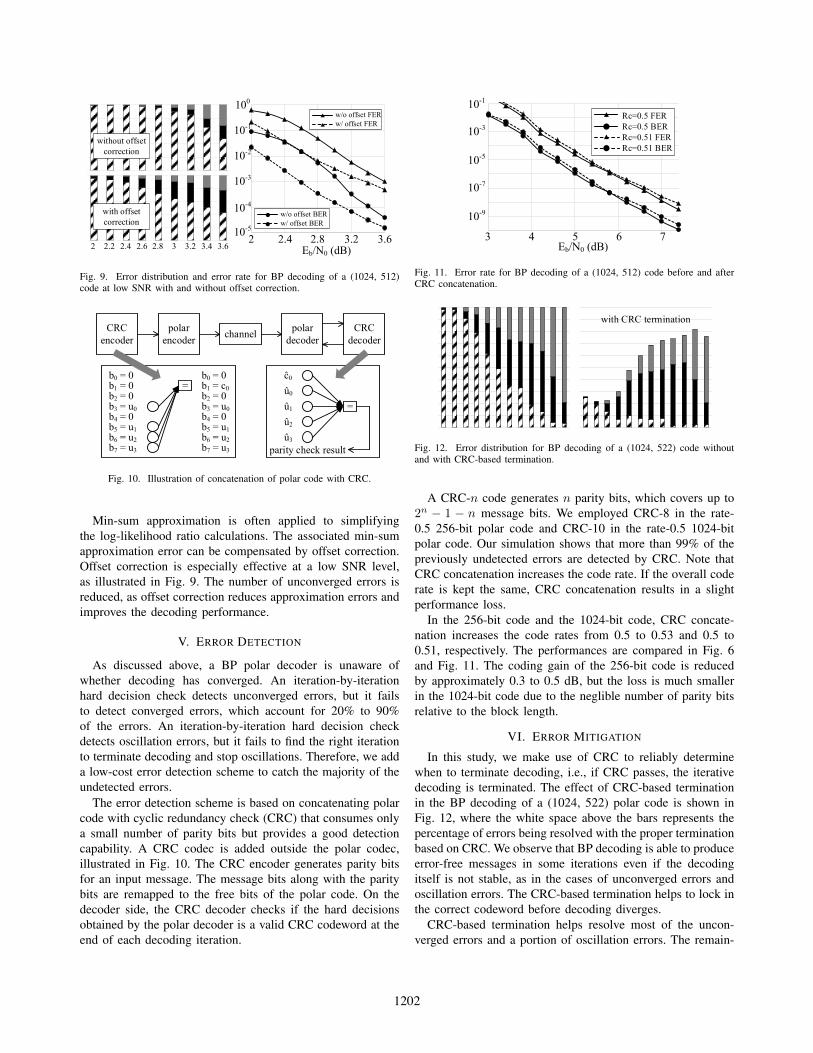
In this study, we make use of CRC to reliably determinewhen to terminate decoding, i.e., if CRC passes, the iterativedecoding is terminated. The effect of CRC-based terminationin the BP decoding of a (1024, 522) polar code is shown inFig. 12, where the white space above the bars represents thepercentage of errors being resolved with the proper terminationbased on CRC. We observe that BP decoding is able to produceerror-free messages in some iterations even if the decodingitself is not stable, as in the cases of unconverged errors andoscillation errors. The CRC-based termination helps to lock inthe correct codeword before decoding diverges.
CRC-based termination helps resolve most of the uncon-verged errors and a portion of oscillation errors. The remain-
1202

ing errors are dominated by converged errors and oscilla-tion errors. One approach to fix the remaining errors is viapost-processing by perturbation. Prior work in LDPC post-processing points out that perturbation is especially beneficialwhen a BP decoder is trapped in a local minimum [8]. Froma cost standpoint, post-processing can be implemented as partof BP decoding with biased messages. We are in the processof completing a full experimentation and analysis of post-processing methods.
VII. CONCLUSION
In this work, we classify BP decoding errors into three cat-egories: unconverged errors, converged errors, and oscillationerrors. We analyze the important factors affecting decoding,including code design and decoder implementation. Whileunconverged errors and oscillation errors are detectable bychecking the hard decisions in each iteration for consistency,converged errors are undetected. Concatenation of polar codeswith CRC enables the detection of undetected errors and theproper termination of BP decoding. CRC-based terminationhelps to remove a large portion of unconverged errors andoscillation errors.
REFERENCES
[1] E. Arikan, “Channel polarization: A method for constructing capacity-achieving codes for symmetric binary-input memoryless channels,” IEEETrans. Inf. Theory, vol. 55, no. 7, pp. 3051–3073, July 2009.
[2] A. Pamuk, “An FPGA implementation architecture for decoding of polarcodes,” in Int. Symp. Wireless Commun. Syst., Nov 2011, pp. 437–441.
[3] B. Yuan and K. K. Parhi, “Architecture optimizations for BP polardecoders,” in IEEE Int. Conf. Acoustics, Speech and Signal Process.,May 2013, pp. 2654–2658.
[4] I. Tal and A. Vardy, “List decoding of polar codes,” in IEEE Int. Symp.Inf. Theory, July 2011, pp. 1–5.
[5] T. Richardson, “Error floors of LDPC codes,” in Proc. Annu. AllertonConf. Commun. Control and Computing, vol. 41, no. 3, 2003, pp. 1426–1435.
[6] C. Leroux, A. J. Raymond, G. Sarkis, and W. J. Gross, “A semi-parallelsuccessive-cancellation decoder for polar codes,” IEEE Trans. SignalProcess., vol. 61, no. 2, pp. 289–299, Jan 2013.
[7] S. Sun and Z. Zhang, “Architecture and optimization of high-throughputbelief propagation decoding of polar codes,” in 2016 IEEE Int. Symp.Circuits Syst. (ISCAS), May 2016, pp. 165–168.
[8] Z. Zhang, L. Dolecek, B. Nikolic, V. Anantharam, and M. J. Wainwright,“Lowering LDPC error floors by postprocessing,” in 2008 IEEE GlobalTelecommunications Conf., Nov 2008, pp. 165–168.
1203