ERNG-X - Emerson · (14.75 x 5 inch / 374.7 x 127 mm Bolt Pattern) ... LabVIEW, C and C# ... ER5000...
6
Description The ERNG-X is a steady state no bleed engineered system for accurate and reliable control of Natural Gas. The ERNG-X includes a pressure regulator, preconditioning filters, and an electropneumatic controller for automated control. The ERNG-X is panel mounted and can be easily installed in an enclosure or on a wall. Applications • Automated natural gas pressure or flow control ERNG-X DERNG2108X012 ELECTRICAL Power Requirement 20.5 to 28.5 VDC, 340 mA maximum, 180 mA nominal Turn-on Time < 240 milliseconds Restart from Power Interruption < 1.9 seconds SUPPLY REQUIREMENT Media Type Natural Gas with a maximum upper explosion limit below 18% by volume at atmospheric conditions Media Quality: Corrosives: H 2 S and other sulfides below 10 ppm Impurities: CO 2 below 3%; O 2 below 0.5% Pressure System: Maximum: 2750 psig / 190 bar ER5050FX-1-002: Maximum: 110 psig / 7.5 bar Minimum: Outlet pressure 1 psig / 0.07 bar Temperature Dry gas required below 32°F / 0°C ERNG: -4°F to 140°F / -20°C to 60°C INPUT SIGNALS Setpoint USB, RS485, Downloaded Profile 4-20 mA, 1-5 VDC (ERNG-I) 0-10 VDC (ERNG-V) Feedback (external) ERNG-I: 4-20 mA or 1-5 VDC ERNG-V: 0-10 VDC PERFORMANCE (1) Accuracy Measured Reference Accuracy (total accuracy all effects including zero and span error): ± 0.10% (FSO) Low Pressure Capability with External Transducer ± 0.25 inches water (0.635 g/sq. cm) into 2 liter volume Response Time Sensor Update Rate: 500 milliseconds (can be adjusted between 25 milliseconds and 2,500 milliseconds) Flow Capacity: C v = 0.01 (Maximum Flow = 18 SLPM) Solenoid Valve Rated Cycle Life: > 150 million cycles PHYSICAL Size Gas Ports Inlet: 1/4 - 18 NPT Exhaust and Gauge: 1/8 - 27 NPTF Control Port: 1/2 inch SAE with supplied adapter to 1/8 -27 NPT Male Height: 8.5 inches / 216 mm Length: 15.75 inches / 400 mm Width: 6 inches / 152 mm Conduit Openings: Two, 1/2 NPTF Weight ERNG: 12.5 lbs / 5.7 kg ER5050FX-1-002 Housing Standard: NEMA 4X IP66 (aluminum and epoxy polyester paint) Optional: Stainless steel Flow Stream Materials Solenoids: Nickel-plated Brass, FKM Seat and O-rings Fittings: Brass, 316 SST Seats: FKM, PCTFE, PTFE, DELRIN Body: Aluminum, 316 SST, Brass, Nickel Plated Brass Filter Element: Borosilicate Glass Sensor: Glass, Ceramic, Silicon, RTV, Nickel Tubing: Polyurethane, 316 SST O-rings: Buna-N, FKM Teflon Mounting Four through holes that allow 3/8" or 9 mm bolts (14.75 x 5 inch / 374.7 x 127 mm Bolt Pattern) Mounting Orientation Effect Filter Drain Vertically Down ERNG-X Specifications 1. With clean dry sweet gas. - continued - www.tescom.com
Transcript of ERNG-X - Emerson · (14.75 x 5 inch / 374.7 x 127 mm Bolt Pattern) ... LabVIEW, C and C# ... ER5000...

DescriptionThe ERNG-X is a steady state no bleed engineered system for accurate and reliable control of Natural Gas. The ERNG-X includes a pressure regulator, preconditioning filters, and an electropneumatic controller for automated control. The ERNG-X is panel mounted and can be easily installed in an enclosure or on a wall.
Applications• Automated natural gas pressure or flow control
ERNG-X DERNG2108X012
ELECTRICAL
Power Requirement20.5 to 28.5 VDC, 340 mA maximum, 180 mA nominal
Turn-on Time< 240 milliseconds
Restart from Power Interruption< 1.9 seconds
SUPPLY REQUIREMENT
Media TypeNatural Gas with a maximum upper explosion limit below 18% by volume at atmospheric conditionsMedia Quality:Corrosives: H2S and other sulfides below 10 ppmImpurities: CO2 below 3%; O2 below 0.5%
PressureSystem: Maximum: 2750 psig / 190 barER5050FX-1-002: Maximum: 110 psig / 7.5 barMinimum: Outlet pressure 1 psig / 0.07 bar
TemperatureDry gas required below 32°F / 0°CERNG: -4°F to 140°F / -20°C to 60°C
INPUT SIGNALS
Setpoint USB, RS485, Downloaded Profile4-20 mA, 1-5 VDC (ERNG-I)0-10 VDC (ERNG-V)
Feedback (external)ERNG-I: 4-20 mA or 1-5 VDCERNG-V: 0-10 VDC
PERFORMANCE(1)
AccuracyMeasured Reference Accuracy (total accuracy all effects
including zero and span error): ± 0.10% (FSO)Low Pressure Capability with External Transducer
± 0.25 inches water (0.635 g/sq. cm) into 2 liter volume
Response TimeSensor Update Rate: 500 milliseconds (can be adjusted between 25 milliseconds and 2,500 milliseconds)
Flow Capacity: Cv = 0.01 (Maximum Flow = 18 SLPM) Solenoid Valve Rated Cycle Life: > 150 million cycles
PHYSICAL
SizeGas PortsInlet: 1/4 - 18 NPTExhaust and Gauge: 1/8 - 27 NPTF Control Port: 1/2 inch SAE with supplied adapter to 1/8 -27 NPT MaleHeight: 8.5 inches / 216 mmLength: 15.75 inches / 400 mmWidth: 6 inches / 152 mmConduit Openings: Two, 1/2 NPTF
WeightERNG: 12.5 lbs / 5.7 kg
ER5050FX-1-002 HousingStandard: NEMA 4X IP66 (aluminum and epoxy polyester paint)Optional: Stainless steel
Flow Stream MaterialsSolenoids: Nickel-plated Brass, FKM Seat and O-ringsFittings: Brass, 316 SSTSeats: FKM, PCTFE, PTFE, DELRINBody: Aluminum, 316 SST, Brass, Nickel Plated BrassFilter Element: Borosilicate GlassSensor: Glass, Ceramic, Silicon, RTV, NickelTubing: Polyurethane, 316 SSTO-rings: Buna-N, FKM Teflon
MountingFour through holes that allow 3/8" or 9 mm bolts (14.75 x 5 inch / 374.7 x 127 mm Bolt Pattern)
Mounting Orientation EffectFilter Drain Vertically Down
ERNG-X Specifications
1. With clean dry sweet gas.
- continued -
www.tescom.com

578
ERNG-X Specifications (continued)
ENVIRONMENT
Temperature Range-4°F to 140°F / -20°C to 60°C
Relative HumidityTo 100% R.H. (non-condensing at 32°F to 140°F / 0°C to 60°C)
Storage Temperature-58°F to 200°F / -50°C to 93°C
Features and BenefitsERNG-I
• Precise accuracy• 16 Bit for Data Acquisition• Steady state no bleed• Control algorithms for Internal Feedback, External
Feedback or Cascade Control modes• Selectable SETPOINT Signal Source
- USB (Not recommended)- RS485- External analog (4-20mA or 1-5VDC)- Downloadable Profile (runs independent of PC or
external analog source)• Selectable FEEDBACK Signal Source
- Internal Sensor (0-100 psig / 0-6.9 bar)- External Analog: 4-20mA or 1-5VDC
• Selectable Control Limits- Programmable limits for analog setpoint,
feedback and error signals- Selectable control states: “Hold Last Pressure”, “Vent”,
or “Full Open”• TESCOM ERTuneTM software provided for data acquisition,
PID tuning (real time graphic display of setpoint and feedback), creating and downloading profiles
• TESCOM DLL provided for easy custom software development
• Software examples are provided for VB.NET, LabVIEW, C and C#
• Trigger data acquisition based on system events
• Two additional analog/digital inputs and two digital outputs that allow the user to:
- Monitor an external signal in addition to feedback (e.g. flow, temp, force)
- Alternate between two separate external feedback sources
- Start/Stop or Resume/Pause pressure profiles
- Wait for event to occur before proceeding to the next step in a downloaded profile (digital input)
- Indicate that an event occurred in a downloaded profile (digital output)
• Analog output of the internal pressure sensor
• Conditional control with "IF/THEN" and "GoTo" profile commands
• Suspend control feature to lock output pressure for an extended period of time
• ER5050FX-1-002: NEMA 4X and IP66 (water tight, corrosion resistant)
ERNG-V
• All features of the ERNG-I except with 0-10 VDC Setpoint and Feedback signals
CERTIFICATIONS
CE ApprovalAll ER5000 units have CE approval when wired per CE approved wiring instructions in the ER5000 User Manual
Hazardous Location Approvals on ER5050FX-1-002 OnlyCSA, IECEx, ATEXClass I, DIV 1, Groups BCD T5Class II, DIV 1, Groups EFGClass IIIEx db IIB+H2 T5 GbEx tb IIIC T100°C Db IP6XZone 1, AEx d IIB+H2 T5 GbZone 21, AEx tb IIIC T100°C Db IP6X
Special Control Features Available
- Suspend Mode- Diaphragm protection- Pulse Mode- Control Limits

579
ERNG-X Dimensions
All dimensions are reference & nominal Metric [millimeter] equivalents are in brackets
15.75[400.0]
8.3[210.8]
14.75[374.6]
5.0[127.0]
4X Ø9.92 mm
2X 1/4" – 18 NPT
2X 1/4" – 18 NPT
3.0[76.2]
1.9[47.2]
1.0[26.1]
4.9[123.4]
11.2[283.3]
2.5[64.0]
FRONT VIEW
BOTTOM VIEW
LEFT SIDE VIEW RIGHT SIDE VIEW
5.7[144.1]
6.0[152.4]
0.9[22.6]
2.4[61.0]
1.1[27.5]
2X 1/2" – 14 NPTF
1.0[26.1]
1.1[28.6]
0.9[23.5]
1/8" – 27 NPTF
1/4" – 18 NPT
BREAK OUT SECTION
3X 1/4" – 18 NPT1/2" SAE(ADAPTOR FITTING INCLUDED TO ADAPT TO MALE 1/8" NPT)
Figure 1. ERNG-X Dimensions

580
ERNG-X Typical Applications
The following diagram is an example of a typical ERNG-X application. Remote set point control for a district station. The ERNG-X controls the downstream pressure on the pipeline main regulator by varying the spring case pressure of the pipeline pilot regulator.
PIPELINE PILOT
REGULATOR
ANALOG SETPOINT
SIGNAL (4-20 mA)
EXTERNAL PRESSURE OR
FLOW TRANSDUCER
(4-20 mA)
PIPELINE MAIN REGULATOR
REMOTE OPERATIONS CONTROLLER (ROC)
ERNG-X
Figure 2. ERNG-X Typical Applications
581
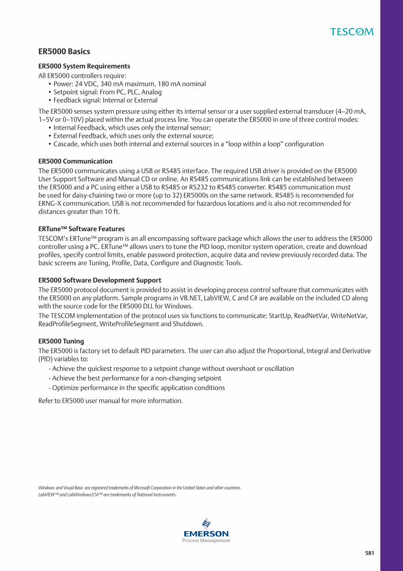
ER5000 Basics
ER5000 System RequirementsAll ER5000 controllers require:
• Power: 24 VDC, 340 mA maximum, 180 mA nominal • Setpoint signal: From PC, PLC, Analog • Feedback signal: Internal or External
The ER5000 senses system pressure using either its internal sensor or a user supplied external transducer (4–20 mA, 1–5V or 0–10V) placed within the actual process line. You can operate the ER5000 in one of three control modes:
• Internal Feedback, which uses only the internal sensor; • External Feedback, which uses only the external source; • Cascade, which uses both internal and external sources in a “loop within a loop” configuration
ER5000 CommunicationThe ER5000 communicates using a USB or RS485 interface. The required USB driver is provided on the ER5000 User Support Software and Manual CD or online. An RS485 communications link can be established between the ER5000 and a PC using either a USB to RS485 or RS232 to RS485 converter. RS485 communication must be used for daisy-chaining two or more (up to 32) ER5000s on the same network. RS485 is recommended for ERNG-X communication. USB is not recommended for hazardous locations and is also not recommended for distances greater than 10 ft.
ERTune™ Software FeaturesTESCOM’s ERTune™ program is an all encompassing software package which allows the user to address the ER5000 controller using a PC. ERTune™ allows users to tune the PID loop, monitor system operation, create and download profiles, specify control limits, enable password protection, acquire data and review previously recorded data. The basic screens are Tuning, Profile, Data, Configure and Diagnostic Tools.
ER5000 Software Development SupportThe ER5000 protocol document is provided to assist in developing process control software that communicates with the ER5000 on any platform. Sample programs in VB.NET, LabVIEW, C and C# are available on the included CD along with the source code for the ER5000 DLL for Windows.The TESCOM implementation of the protocol uses six functions to communicate: StartUp, ReadNetVar, WriteNetVar, ReadProfileSegment, WriteProfileSegment and Shutdown.
ER5000 TuningThe ER5000 is factory set to default PID parameters. The user can also adjust the Proportional, Integral and Derivative (PID) variables to: - Achieve the quickest response to a setpoint change without overshoot or oscillation - Achieve the best performance for a non-changing setpoint - Optimize performance in the specific application conditions
Refer to ER5000 user manual for more information.
Windows and Visual Basic are registered trademarks of Microsoft Corporation in the United States and other countries.LabVIEW™ and LabWindows/CVI ™ are trademarks of National Instruments.
582
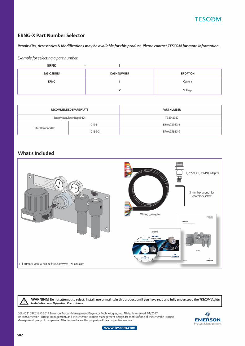
ERNG-X Part Number Selector
RECOMMENDED SPARE PARTS PART NUMBER
Supply Regulator Repair Kit JT389-8927
Filter Elements KitC195-1 ERAA23983-1
C195-2 ERAA23983-2
What's Included
Repair Kits, Accessories & Modifications may be available for this product. Please contact TESCOM for more information.
Example for selecting a part number:
ERNG - I
BASIC SERIES DASH NUMBER ER OPTION
ERNG I
V
Current
Voltage
Full ER5000 Manual can be found at www.TESCOM.com
3 mm hex wrench for cover lock screw
1/2" SAE x 1/8" NPTF adapter
Wiring connectorInstruction Manual
dopsm2107x012december 2016
ERNG-XTEsCom product manual
Figure 1. ERNG-X
WARNING! Do not attempt to select, install, use or maintain this product until you have read and fully understood the TESCOM Safety, Installation and Operation Precautions.
DERNG2108X012 © 2017 Emerson Process Management Regulator Technologies, Inc. All rights reserved. 01/2017.Tescom, Emerson Process Management, and the Emerson Process Management design are marks of one of the Emerson Process Management group of companies. All other marks are the property of their respective owners.
www.tescom.com

![netlusa.comnetlusa.com/desbravadores.pt/images/MANUAIS/Manual_Caes.pdf · ï } / v } µ ] } x x x x x x x x x x x x x x x x x x x x x x x x x x x x x x x x x x x x x x x x x x x x](https://static.fdocuments.us/doc/165x107/5be3717009d3f20a668b6378/-i-v-x-x-x-x-x-x-x-x-x-x-x-x-x-x-x-x-x-x-x-x-x-x-x-x-x-x-x-x-x.jpg)
![t y r r s - RUN: Página principal · À ] ] 1e / 'z /d edk^ x x x x x x x x x x x x x x x x x x x x x x x x x x x x x x x x x x x x x x x x x x x x x x x x x x x x x x x x x x x](https://static.fdocuments.us/doc/165x107/5baf4cc109d3f2c70e8c393e/-t-y-r-r-s-run-pagina-principal-a-1e-z-d-edk-x-x-x-x-x-x-x-x.jpg)