
ergoselect 10 - 4337408.s21d-4.faiusrd.com
62
Manual ergoselect 10 Couch Ergometer Operator's Manual 201000546000 • Version 2018-10-08 / Rev 01 • English
Transcript of ergoselect 10 - 4337408.s21d-4.faiusrd.com

Man
ual
ergoselect 10Couch Ergometer
Operator's Manual
201000546000 • Version 2018-10-08 / Rev 01 • English

ergoselect 10 1
This manual was written with the utmost care. Should you still find details that do not correspond with the system, please let us know and we will correct the issue as soon as possible.
We reserve the right to modify the design and technical features and are not bound by the information and illustrations provided in this manual.
All trademarks appearing in this document are trademarks of their respective owners. Their protection is acknowledged.
No part of this manual may be reprinted, translated or reproduced without the manufacturer's written permission.
This manual will not be automatically updated. Please contact the manufacturer for the latest document revision.
This manual also describes optional components that are not included in the standard scope of delivery of this product.
ergoline GmbHLindenstrasse 572475 BitzGermany
Tel.: +49-(0)-7431 - 9894 - 0Fax: +49-(0)-7431 - 9894 - 128e-mail: [email protected]: www.ergoline.com
Printed in Germany
ergoselect 10Couch Ergometer
Operator's Manual
201000546000 • Version 2018-10-08 / Rev 01 • English

2 ergoselect 10

ergoselect 10 3
Contents
1 General Information 5
2 Safety Information 62 1 Safety Information for Non‑Invasive Blood Pressure Measurement 72 2 Contraindications 72 3 Intended Use 72 4 Biocompatibility 72 5 Applicable Laws, Regulations and Directives 8
3 Symbols 9
4 Setup and Mains Connection 104 1 Controls and Indicators 104 2 Transport 104 3 Setup 114 4 Mounting Attachment Parts 114 5 Connecting the Power Cord 134 6 Connecting the ECG Cable 144 7 Start‑up and Preparation 14
5 Operation 165 1 Adjusting the Couch 16
6 Preparing the Patient 176 1 Preparing the Couch with the Patient 17
7 Preparing the Patient for Blood Pressure Measurements 187 1 Cuff Size 187 2 Microphone Position 187 3 Applying the Cuff 19
8 Control Terminals 208 1 Control Terminal M 20
8 1 1 Turning the System On 208 1 2 Operating Mode with Control Terminal M 21
8 2 Control Terminal P 228 2 1 Turning the System On 228 2 2 Operating Modes 23
8 3 Control Terminal T 328 3 1 Turning the System On 328 3 2 Operating Modes with Control Terminal T 33
Contents

4 ergoselect 10
9 Cleaning, Maintenance, Disposal 479 1 General Cleaning 479 2 Cleaning the Saddle 479 3 Disinfection 479 4 Cleaning the Blood Pressure Cuff 48
9 4 1 Removing the Microphone 489 4 2 Cleaning 489 4 3 Disinfection 489 4 4 Inserting the Microphone 49
9 5 Maintenance 499 5 1 Checks Before Each Use 499 5 2 Technical Safety Inspections and Inspections of the Measuring System 49
9 6 Disposal 49
10 Technical Specifications 5010 1 Ergometer 5010 2 Blood Pressure Module 5110 3 Exercise Test Protocols 5210 4 Test Protocols (control terminal T only) 5210 5 Family of characteristics of the braking torque control range 5310 6 Family of characteristics of the load periods according to IEC 60601‑1 53
11 Electromagnetic Compatibility EN 60601-1-2 54

1 General Information
ergoselect 10 5ergoselect 10 5
1 General Information• The product ergoselect bears the CE marking CE‑0123
(Notified Body: TÜV), indicating its compliance with the provisions of the Council Directive 93/42/EEC about medical devices and fulfills the essential requirements of Annex I of this directive. The CE marking covers only the accessories listed in the Order Information chapter. The device is an MDD class IIa product.
• The device fulfills the requirements of the standard EN 60601‑1 "Medical electrical equipment, Part 1: General Requirements for Safety" as well as the inter‑ference protection requirements of standard EN 60601‑1‑2 "Electromagnetic Compatibility – Medical Electrical Devices". The radio‑interference emitted by this device is within the limits specified in EN 55011, class B.
• The symbol means: Protection class I.
• This manual is an integral part of the device. It should be available to the equipment operator at all times. Close observance of the information given in the manual is a prerequisite for proper device performance and correct operation and ensures patient and operator safety. Please note that information pertinent to several chapters is given only once. Therefore, read the manual once carefully in its entirety.
• The symbols mean: Consult accompanying documents. They indicate points that are of particular importance in the operation of the device.
• Observance of the safety information protects from injuries and prevents inappropriate use of the device. All device users and persons responsible for assembly, maintenance, inspection and repair of the device must read and understand the content of this manual, before using the device or working with it. Paragraphs with special symbols are of particular importance.
• By opening the control terminal, you will damage the calibration sticker. This will automatically void the warranty.
• This manual reflects the device specifications and appli‑cable safety standards valid at the time of printing. All rights are reserved for devices, circuits, techniques, software programs, and names appearing in this manual.
• On request ergoline GmbH will provide a Field Service Manual.
• The implemented quality management system covers all aspects of the ergoline GmbH operations as per EN ISO 13485: 2016.
• The safety information given in this manual is classified as follows:
Dangerindicates an imminent hazard. If not avoided, the hazard will result in death or serious injury.
Warningindicates a hazard. If not avoided, the hazard may result in minor injury and/or product/property damage.
Cautionindicates a potential hazard. If not avoided, the hazard may result in minor injury and/or product/property damage.
• To ensure patient safety, the specified measuring accu‑racy, and interference‑free operation, we recommend using only original ergoline GmbH accessories. The user is responsible if accessories from other manufacturers are used.
• ergoline GmbH is responsible for the safety, reliability, and performance of the device, only if— assembly operations, extensions, readjustments,
modifications, or repairs are carried out by ergoline GmbH or by an organization expressly authorized by ergoline GmbH to carry out these tasks
— the equipment is used in accordance with the instructions given in this operator manual.
ergoline GmbH Lindenstrasse 5 72475 Bitz Germany
Tel.: +49-(0)-7431 - 9894 - 0 Fax: +49-(0)-7431 - 9894 - 128 email: [email protected] http: www.ergoline.com

2 Safety Information
6 ergoselect 10
2 Safety Information
Danger• Explosion Hazard •
The device is not designed for use in areas where an explosion hazard may occur. Explosion hazards may result from the use of flammable anesthetics, skin cleansing agents, or disinfectants.
Warning• Patient Hazard, Equipment Damage •
Do not expose the ergoselect to direct sunlight to prevent system components from reaching inadmissible high temperatures.
Do NOT use the ergoselect outdoors (medical device). Furthermore the device has no additional protection against the ingress of humidity. Humidity inside the device may cause equipment malfunctions and increases the risk of an electric shock.
Additionally, the device should not be operated in the vicinity of power systems, because they may impair equipment functions.
The ergoselect may only be used in combination with accessories approved by ergoline GmbH.
• Risk to Persons •Before using the ergometer, the operator must ascertain that it is in correct working order and operating condition. The cables and connectors, in particular, must be checked for signs of damage. Damaged parts must be replaced immediately.
• Equipment Malfunction •Only the special shielded cables supplied by ergoline GmbH may be used to connect the device to other pieces of equipment.
• Equipment Malfunction •Cellular telephones may not be used in the immediate vicinity of the ergometer, because they might interfere with the proper functioning of the ergometer. Electromagnetic interference most probably exists when the watt reading is unstable. If the displayed value changes frequently even though the speed is above 30 RPM, this may be due to electromagnetic interference.
NoteThe device characteristics determined by emissions allow the device to be used in industrial environments and in hospitals (CISPR 11, class A). When used in domestic surroundings (which normally requires compliance with CISPR 11 class B), the device may not offer adequate protection for radio services. If required, the user may have to take remedial action by relocating or reorienting the device.
Warning• Shock Hazard •
When the device is connected to other equipment or if a medical system is created, it must be ensured that the added leakage currents do not present a hazard. In case of questions, please contact your ergoline dealer or the ergoline GmbH Service Department.
For use, the ergometer must always be connected to electric installations that fulfill the local requirements.
• Patient Hazard •The German Medical Device Operator Ordinance (MPBetreibV, § 5) demands that users• must be trained in the use of the ergometer • must be familiar with the routines for handling and assem
bly of the device• must be familiar with and observe the safety rules and
regulations for operation of this type of equipment• must be informed about any other pertinent rules and
regulations (e.g., safety instructions)• must be informed about the potential hazards arising from
the use of this type of equipment• make sure that no unauthorized changes are carried out.
NoteOnly the removal of the power cord will result in an allpole disconnection of the device from the power line.
CautionAdditional equipment connected to medical electrical equipment must comply with the respective IEC or ISO standards (e.g., IEC 60950 for data processing equipment).Furthermore all configurations shall comply with the requirements for medical electrical systems (see IEC 6060111 or clause 16 of the 3rd edition of IEC 606011, respectively).
Anybody connecting additional equipment to medical electrical equipment configures a medical system and is therefore responsible for the system's compliance with the requirements for medical electrical systems. Attention is drawn to the fact that local laws take priority over the above mentioned requirements.
If in doubt, please consult your local dealer or ergoline GmbH.

2 Safety Information
6 ergoselect 10 ergoselect 10 7
2.1 Safety Information for Non‑Invasive Blood Pressure Measurement
Warning• Patient Hazard •
Do not take blood pressure measurements with a cuff on patients suffering from sickle cell anemia or if skin lesions are likely to occur.
The cuff may cause hematomas in patients with severe blood coagulation disease. In these instances, the user must take a decision for or against automatic blood pressure measurements.
Caution• Compromised Measuring Accuracy •
Arrhythmias occurring frequently during a measurement may compromise the accuracy of the measurement.Valid measurements may not be possible under certain circumstances.
Electromagnetic fields are also capable of impairing the measuring accuracy.
Note• If the cuff pressure exceeds the maximum value of 300 mmHg
during inflation, the inflation procedure will be aborted and the cuff deflated. As a redundant safety precaution, the cuff is immediately deflated when the cuff pressure exceeds 320 mmHg. You can check the proper functioning of this safety precaution by abruptly bending your arm while the cuff is being inflated, causing a brief overpressure in the cuff. The cuff must deflate immediately.
• Measurements that do not yield a valid measurement will not be repeated during the exercise test.
• If the inflation phase takes longer than 40 seconds or if an adequate pressure does not build up in the cuff within a reasonable period of time, the measurement will be aborted and the cuff deflated.
• If a valid measurement cannot be completed within 120 seconds, the measurement will be aborted and the cuff deflated.
• If the cuff pressure remains constant for some time, the measurement will also be aborted and the cuff deflated.
2.2 ContraindicationsThe following patient categories are excluded from using the device:• patients feeling discomfort or suffering from dizziness,
nausea or pain.• patients under the influence of substances that may
impair vigilance (alcohol, drugs, medication).
2.3 Intended UseThe ergoselect 10 is a computer‑controlled medical ergo‑meter, which operates at pedal speeds between 30 and 130 RPM and loads between 6 and 999 W.The speed‑independent range is shown in the Appendix (Technical Specifications).
The ergoselect ergometers may only be used in exercise testing and for rehabilitation of cardiac and cardiovas‑cular patients according to the instructions given in this manual. If the ergometer is used for other purposes, the manufacturer cannot be held liable for personal injuries or property damage resulting from the unintended use of the equipment.
Note – Applied Parts• Applied parts are components that are directly in contact
with the human body (e.g., blood pressure measuring devices).
Note – Stability• Ensure the stability of the ergometer. If the maximum per
mitted patient weight is exceeded by +10 %, the stability of the ergometer can no longer be guaranteed. It may become unstable as a result.
2.4 BiocompatibilityThe parts of the product described in this manual, includ‑ing all accessories that come in contact with the patient during the intended use, fulfill the biocompatibility require‑ments of the applicable standards if applied as intended.
If you have questions in this matter, please contact ergoline GmbH or an ergoline GmbH representative.

2 Safety Information
8 ergoselect 10
2.5 Applicable Laws, Regulations and Directives
If you have questions about the validity of applicable laws, regulations and directives, please contact ergoline GmbH.

3 Symbols
8 ergoselect 10 ergoselect 10 9
3 SymbolsSymbol 'type B applied part' Type B applied parts have no direct contact with patients and offer the lowest protection against electric shock
Symbol 'type BF applied part' Type BF applied parts are connected to the body of the patient and provide a higher degree of protec‑tion against electric shock The applied parts are isolated
Caution: Consult accompanying documents
Protection class I equipment
This symbol indicates that the waste of electrical and electronic equipment must not be disposed of as unsorted municipal waste and must be collected separately Consult Operating Manual!
Order number
Serial number
Scheduled date of the next inspection (e g , March 2017)
Toggle switch ON (voltage)
Toggle switch OFF (voltage)
CE mark per the Medical Device Directive 93/42/EEC of the European Union Notified body: TÜV SÜD Product Service GmbH, Ridlerstr 65, 80339 München, Germany
Nationally Recognized Testing Laboratory NRTL label for the USA and Canada
Emergency lowering button OFF (stable position) button ON (only while button is being pressed)
nächsterPrüftermin
gemäss MPBetreibV20 21
22
191817010203
04 05 06 07 0809
101112
E m
e rg e n
cy
Manufacturer’s identification
Date of manufacture The number found under this symbol is the date of manufacture in the YYYY‑MM‑DD format
PVC‑free
Latex‑free
Suitable for the indicated arm circumference
Small size
Standard size
Large size
Transport and storage label: top
Transport and storage label: keep dry
Transport and storage label: fragile
Transport and storage label: approved temperature range
Transport and storage label: approved humidity range, non‑condensing
Transport and storage label: approved pressure range
Transport and storage label: do not stack

4 Setup and Mains Connection
10 ergoselect 10
4 Setup and Mains Connection4.1 Controls and Indicators1 Speed readout for the patient
2 Arm rest for blood pressure measurements (right or left, only on devices with automatic blood pressure measurement)
3 Connections for blood pressure cuff (below the couch surface)
4 Release lever for ergometry unit
5 Connections for power cord and connection cables (under the cover panel)
6 Knob for adjustment of the headrest
7 Exam table paper roll
8 Type plate (on the back of the table column)
9 Remote control
3
1
2
4
5
76
8
Figure 4 – 1: Controls ergoselect 10
9
Figure 4 – 2: Remote control
4.2 TransportThe ergoselect 10 is quite large and heavy. Therefore, the Couch Ergometer will be shipped to you and set up by a qualified carrier.
Caution• Equipment Damage •
Avoid strong vibrations of the Couch Ergometer during transport.

4 Setup and Mains Connection
10 ergoselect 10 ergoselect 10 11
4.3 Setup
Several persons should be present to set up the ergoselect 10.
The ergoselect 10 must be set up on a horizontal level floor.
The Couch Ergometer must be set up in a secure and stable position! The leveling feet make for easy adjustment to uneven floors.
During setup, the six leveling feet need to be screwed into the baseplate. To do this, place the Couch Ergometer carefully on one side and screw the leveling feet into the corresponding borings (see Figure 4 – 3) and align.
Screw in the feet so the Couch Ergometer is standing securely; tighten the counter nut with an open‑end wrench (see Figure 4 – 4).
In case of delicate flooring, it is recommended to place a mat under the ergometer to protect the flooring from damage by the feet.
Caution• Patient Hazard / Equipment Damage •
During assembly, the ergometer must be disconnected from the power line.
1
6
2
5
3
4
Figure 4 – 3: Position of the leveling feet
Figure 4 – 4: Aligning the leveling feet
4.4 Mounting Attachment Parts
• Generally you slide the attachment parts onto the stan‑dard rails 1 on the side and secure them.
• Loosen the set screw 2 of the attachment part before placing it on the standard rail.
• Always position and move the attachment parts care‑fully on the standard rail 3 . Do not force the attach‑ment parts onto the standard rail!
• Slide the attachment part to the appropriate position 4 and secure by tightening the set screw 2 .
3
4 2
1
Figure 4 – 5: Mounting attachment parts
Note• Patient Safety •
Always secure attachment parts by turning the set screw clockwise.
When mounting attachment parts with perforated rails, make sure that the bolts of the knobs engage properly in the rails before tightening the knobs by turning them clockwise.

4 Setup and Mains Connection
12 ergoselect 10
• Mount the holder for the exam table paper roll by means of two countersunk screws M6x20 1 which are screwed into the frame.
Figure 4 – 6: Mounting the holder for the exam table paper roll
Caution• Equipment Damage •
Use only white exam table paper.Colored paper may leave stains on the padded surface.
• Install, position, and secure the headrest 1 .
• Install, position, and secure the speed readout for the patient 2 .
• Install, position, and secure the bracket for the armrest 3 on the right or left standard rail (only on devices
with blood pressure module).
• Connect the blood pressure cuff 4 (see Figure 4 – 8).
• Introduce the saddle post 5 in the saddle guide rail (see Figure 4 – 9).
• Attach the exam table paper roll to the holder 6 .
12
345
6
Figure 4 – 7: Mounting attachment parts
Note• Tighten the set screw only as much as necessary, NOT with
maximum force.
• Grease the threads of the set screws every 3 months at minimum, using a suitable grease, such as OKS470.
• Insert the microphone connector of the blood pressure cuff into the socket 1 and press down until it locks into place.
• Insert the tube connector of the blood pressure cuff into the socket 2 until the retaining ring locks into place.
• Check the cuff tubes and make sure they are not kinked or bent.
1 2
Figure 4 – 8: Connecting the blood pressure cuff1 Socket for microphone connector2 Socket for tube connector

4 Setup and Mains Connection
12 ergoselect 10 ergoselect 10 13
• Introduce the saddle post into the saddle guide rail 1 and press down lightly until the post locks into place.
1
Figure 4 – 9: Introducing the saddle post into the guide rail
Caution• Equipment Damage •
If your ergometer has a separate control terminal, be sure to route the connection cable to the control terminal out of the way to prevent any stumbling hazard. Furthermore, protect the control terminal from falling down.
4.5 Connecting the Power CordThe connection panel is located in the baseplate under the cover panel.
• Plug the power cord into the socket.
• Secure the power cord with a strain relief.
4
1 2
3
Figure 4 – 10: Connection panel in the baseplate1 Socket for power plug2 Socket for USB connector, type B3 Socket for digital connection (Port 1)4 Cover
Warning• Equipment Damage •
For operation, the ergometer must be connected to a properly installed, grounded power socket.
Caution• Equipment Damage •
Before connecting the ergometer to the power line, check that the line voltage corresponds to the ratings on the type plate. The type plate is located at the bottom of the table column.

4 Setup and Mains Connection
14 ergoselect 10
4.6 Connecting the ECG CableThe ergoselect ergometers can be connected to electrocar‑diographs and PC‑based ECG systems of most manufac‑turers.
Different connection cables are available to support differ‑ent communication modes (digital, analog, remote start, etc.).
All ergoselect ergometers are equipped with a digital interface.
(Special adapters are needed for analog control or the remote start capability. Please contact ergoline GmbH for these adapters.)
The connection cable is plugged into the USB port 1 or the 9‑pole socket of the connection panel (Port 1) 2 and secured at the metal frame with an additional strain relief.
21
Figure 4 – 11: Connection for ECG recorder / PC ECG system1 USB PC connection via USB (virtual COM)2 Port 1 Digital connection (remote control from PC or ECG
recorder), connection for cable adapter (analog inter-face + remote start)
Note• Disconnection from Power Supply •
Pressing the power switch or removing the power cord disconnects the device from the power supply.
Removing the power cord results in a complete disconnection of the device from the power supply (all poles).
Ensure that the power plug is readily accessible at all times.
Note• Connection Cables •
Use only connection cables approved by ergoline GmbH.
A special PC driver software, which can be obtained from ergoline GmbH, is required for operation via the USB port.
4.7 Start‑up and Preparation1 MCU (Motor Control Unit) power supply
240 V DC
2 P2: Patch cable for control terminal (types M, P, T)
3 P3: Patch cable for external speed readout
4 H: ATE wheel speed sensor
5 R1: Remote control cable or receiver for remote control by radio signal
6 R2: free (not assigned)
1 3 5
2 4 6
Figure 4 – 12: Connections

4 Setup and Mains Connection
14 ergoselect 10 ergoselect 10 15
Concerning its functionality, the control terminal on the underside of the Couch Ergometer is equivalent to control terminal M (see section 8.1 Control Terminal M on page 20).
For putting the unit into service, remove the control termi‑nal from below the couch surface. Use a 4‑mm Allen key to loosen the two screws 1 .
The control terminal allows you to adjust a number of parameters (such as the baud rate, EKG type) before use, or to initiate a manual blood pressure measurement.
These adjustments should be referred to a qualified Service Engineer.
1
1
Figure 4 – 13: Control terminal under the couch surface

5 Operation
16 ergoselect 10
5 Operation5.1 Adjusting the CouchThe saddle and the couch position are adjusted with the remote control (see Figure 5 – 1):
Keys 1: saddle adjustmentKeys 2: incline adjustment (0 to 45°)
The yellow indicator 3 is illuminated while any of the adjustment keys is pressed.All movements stop automatically when the end position is reached. Movements also stop when two adjustment keys for a motor are pressed at the same time.
1
2
1
2
3
Figure 5 – 1: Remote control
Caution• Patient Hazard •
The arm rest (for blood pressure measurements) is not designed to support the full body weight and it must not be used as a support when getting on and off the couch.
Note• Motor •
The motor is not suitable for continuous operation. The duty cycle of 10 % (1 min ON / 9 min OFF) must be observed. This means that 1 minute of continuous operation of the control terminal must be followed by a pause of 9 minutes.

6 Preparing the Patient
16 ergoselect 10 ergoselect 10 17
6 Preparing the Patient6.1 Preparing the Couch with the Patient
Before the patient can lie down on the couch, the ergometer must be prepared as follows:
• Lower the saddle to the bottom position.• Remove the saddle.• Adjust the couch to the horizontal position so the
patient can get on the couch without any problems.• Retract the ergometry unit (pedal unit).• Ask the patient to lie down on the couch.• Reinstall the saddle.• Fold out the pedal unit.• Close the straps at both pedals and secure the feet in
the pedal shoes by means of the hook and loop fasteners of the straps.
There should be a 10° angle between the axis formed by the upper body and the thigh when the pedal is in the lower position:
• Adjust the saddle until this angle is achieved.• Adjust the headrest until in contact with the shoulder,
when the head is placed on the head rest.• Choose a position for the speed readout where the
patient can easily read the displayed values.
Now you can adjust the incline of the couch.
Note• Patient Safety •
Always secure attachment parts by turning the set screw clockwise.
When mounting attachment parts with perforated rails, make sure that the bolts of the knobs engage properly in the rails before tightening the knobs by turning them clockwise.
Note• Motor •
The motor is not suitable for continuous operation. The duty cycle of 10 % (1 min ON / 9 min OFF) must be observed. This means that 1 minute of continuous operation of the control terminal must be followed by a pause of 9 minutes.

7 Preparing the Patient for Blood Pressure Measurements
18 ergoselect 10
7 Preparing the Patient for Blood Pressure Measurements7.1 Cuff SizeAlways choose the cuff size suitable for the patient's arm.
The maximum arm circumference is indicated on the cuff.
Figure 7 – 1: Correct cuff size
1 21 2
Figure 7 – 2: Wrong cuff size
7.2 Microphone Position
Before applying the cuff, check the position of the micro‑phone inside the red pocket (on the inside of the cuff):
When the microphone is inside the pocket, its metal side must face the arm.
Figure 7 – 3: Correct microphone position

7 Preparing the Patient for Blood Pressure Measurements
18 ergoselect 10 ergoselect 10 19
7.3 Applying the Cuff
The center of the microphone must be located exactly on the brachial artery. Locate the artery by palpation if required.
The red tab identifies the position of the microphone.
The accurate placement of the microphone is the primary condition for reliable pressure measurement during exer‑cise tests. The cuff must be applied directly on the skin, it may not be applied on top of clothing, paper, etc.Apply the cuff approx. 2 cm above the bend of the elbow. The cuff should be tight, but it should not constrict blood vessels. Make sure that the cuff cannot shift when the patient moves during the exercise test.
Figure 7 – 4: Microphone placement on the artery
When you close the Velcro strap, check that the metal clasp 1 is inside the marked index range 2 , and not outside
(see Figure 7 – 2).
The cuff tab must be located below the metal clasp (see Figure 7 – 5).
Instruct your patient to move as little as possible during a blood pressure measurement and, in particular, to avoid excessive contractions of the muscles in the upper arm. Figure 7 – 5: Correct cuff position (tab)
Caution• Patient Hazard •
Apply the cuff directly on the skin. Make sure that rolled up sleeves do not impede blood circulation in the upper arm.Loose cuffs will cause erroneous measurements; overtight cuffs may constrict blood vessels or cause skin lesions and hematomas.
• Incorrect Measurements •A loose cuff would degrade the accuracy of the measurement. Therefore, the computer aborts the measurement if a minimum pressure is not attained within a few seconds.
Warning• Patient Hazard •
If, by accident, an excessive pressure builds up inside the cuff, either remove the cuff immediately from the arm or disconnect the cuff tubing from the control terminal.The same measures are recommended if the cuff does not deflate correctly.

8 Control Terminals
20 ergoselect 10
8 Control Terminals8.1 Control Terminal D / M
Figure 8 – 1: Control terminal D (Service)
(installed under the couch surface – standard)
Figure 8 – 2: Control terminal M (remote control)
(separate terminal – option)
The two terminals are identical in operating routines and
functionality.
8.1.1 Turning the System On
You turn on the ergometer by pressing the power switch.
The ergometer runs a self-test. Subsequently, the start
screen displays.
Control terminals D / M are entirely operated by remote
control (e.g., from an ECG recorder or a PC).
With this key you initiate a blood pressure measure-
ment. Pressing the key a second time during a measure-
ment will stop the measurement.
Figure 8 – 3: Start screen
Note• Instruct the patient not to pedal while the ergometer is
being turned on and during the self-test.
• Apply the blood pressure cuff to the patient AFTER the
ergometer has been turned on and the self-test completed.

8 Control Terminals
ergoselect 10 21
8.1.2 Operating Mode with Control Terminal D / M
Ergometers with control terminal D / M support the following
operating mode:
PC ModeAn external device (e.g., an ECG recorder, a PC-based ECG
system) controls the ergometer – no intervention at all is
required at the Couch Ergometer.
When the ergometer is switched on, the display shows the
start screen – the ergometer is waiting for commands from
the external ECG unit.
Figure 8 – 4: Start screen
As soon as the ergometer receives commands from the
controlling ECG unit or PC, the exercise test will start and
the corresponding values will be displayed.
The exercise test can only be terminated with the corre-
sponding command from the controlling ECG unit.
Figure 8 – 5: Exercise test screen 1
1 current load (Watt)2 most recent BP value (systolic/diastolic) or cuff
pressure during infl ation and bar graph indicating microphone signal strength (see below)
3 duration of exercise test (min)4 heart rate at the time of the BP measurement (BPM)5 pedal speed (RPM)
Figure 8 – 6: Exercise test screen 2

8 Control Terminals
22 ergoselect 10
8.2 Control Terminal P8.2.1 Turning the System On
You turn on the ergometer by pressing the power switch (toggle switch [ I / 0 ] ). The ergometer runs a self‑test. Subsequently, the main menu displays.
Figure 8 – 7: Control terminal P
Note• Instruct the patient not to pedal while the ergometer is being
turned on and during the selftest.
• Apply the blood pressure cuff to the patient AFTER the ergometer has been turned on and the selftest completed.
• The device can be configured to default to one of the operating modes. If this option is selected, the start screen of the selected operating mode (e.g., Ergometry) will be displayed instead of the main menu. With the key, you can display the main menu.
Figure 8 – 8: Main menu
The ergometer software is controlled with 5 keys:
With this key you display the main menu or return to the previous menu level.
With this key you initiate a blood pressure measure‑ment. A measurement in progress can be aborted with the same key.
The functions of these three softkeys change with the displayed menu – the key label describing the function is shown on the display.
Figure 8 – 9: Keypad P

8 Control Terminals
22 ergoselect 10 ergoselect 10 23
8.2.2 Operating Modes
Ergometers with control terminal P support the following operating modes:
PC Mode An external device (e.g., an ECG recorder, a PC‑based ECG system) controls the ergometer – no intervention at all is required at the ergometer.
Ergometry The ergometer runs an automatic exercise test – some of the corresponding test protocols are user‑configurable and stored in the system. (see section 8.2.2.4 Settings with Control Terminal P on page 27)
Manual The ergometer is controlled manually, i.e., the user per‑forms all load changes via the keypad.
Settings Used to configure the ergometer.
8.2.2.1 PC Mode
Use the softkeys on the right and left (↑ ↓) to position the bar cursor on PC Mode and confirm the selection with Select.
Figure 8 – 10: Main menu
The start screen will be displayed – the ergometer is wait‑ing for commands from the external ECG unit.
Figure 8 – 11: Start screen

8 Control Terminals
24 ergoselect 10
As soon as the ergometer receives commands from the controlling ECG unit or PC, the exercise test will start and the corresponding values will be displayed.
The exercise test can only be terminated with the corre‑sponding command from the controlling ECG unit.
Figure 8 – 12: Exercise test screen 1
1 current load (Watt)2 most recent BP value (systolic/diastolic) or cuff
pressure during inflation and bar graph indicating microphone signal strength (see below)
3 duration of exercise test (min)4 heart rate at the time of the BP measurement (BPM)5 pedal speed (RPM)
Note• All functions are locked while the ergometer is operating in
PC mode, except for the saddle height adjustment and the blood pressure key.
• To reactivate the saddle height adjustment function, press and the arrow keys will again be displayed.
• Additional blood pressure measurements can be initiated with .
Figure 8 – 13: Exercise test screen 2
8.2.2.2 Ergometry
Use the softkeys on the right and left (↑ ↓) to position the bar cursor on Ergometry and confirm the selection with Select.
Figure 8 – 14: Main menu

8 Control Terminals
24 ergoselect 10 ergoselect 10 25
The stored test protocols available for selection will be dis‑played. There are five fixed protocols (protocols 1 to 5, (see section 10.3 Exercise Test Protocols on page 52)), whereas protocols 6 to 15 are user‑programmable.
The protocol menu provides an overview of the test phases.
Example: 50 W / 2 min / 25 Windicates: Basic load of 50 W Stage time of 2 min Load stage of 25 W
Use the softkeys on the right and left (↑ ↓) to position the bar cursor on one of the protocols and confirm the selec‑tion with Select.
Figure 8 – 15: Selecting an exercise test protocol
The exercise test is started with the Start key, a blood pres‑sure measurement at rest may precede the test (depending on the selected exercise test protocol).
When the basic load appears on the display (after approx. 15 seconds or upon termination of the blood pressure measurement) and the patient's RPM indicator blinks, the patient should start pedaling.
Figure 8 – 16: Start of an exercise test
The internal protocol will now control the entire exercise test – the display always indicates the current values.
With the +5 W and –5 W keys, the current load can be changed any time (in increments of +/–1 W up to +/–25 W, as configured).
Figure 8 – 17: Display during the exercise test
Note• The saddle height can be adjusted during an exercise test.
• To activate the saddle height adjustment, press : the arrow keys will be displayed then.
• Additional blood pressure measurements can be initiated with .

8 Control Terminals
26 ergoselect 10
Terminating an Exercise Test
The exercise phase can be terminated manually at any time with the Recovery key.
The load will immediately be reduced to 25 watts, but a higher or lower value can be selected manually.
It is recommended that the patient continue to pedal in the recovery phase.
The End key in the middle will terminate the test. Figure 8 – 18: Recovery phase
8.2.2.3 Manual
Use the softkeys on the right and left (↑ ↓) to position the bar cursor on Manual and confirm the selection with Select.
In this operating mode the user controls the entire exercise test by selecting the loads, stage times and by initiating blood pressure measurements.
Figure 8 – 19: Main menu
The exercise test is started with the Start key, afterwards the load can be set and changed with the +5 W and ‑5 W keys (in increments of +/–1 W up to +/–25 W, as config‑ured).
Blood pressure measurements can be initiated with .
Figure 8 – 20: Initial screen of a manual exercise test
Terminating an Exercise Test
The exercise test can be terminated manually at any time with the End key located in the middle.
The load will immediately drop to 0 watt.
There is no recovery phase in the manual mode.
Figure 8 – 21: Display during the exercise test

8 Control Terminals
26 ergoselect 10 ergoselect 10 27
8.2.2.4 Settings with Control Terminal P
Some of the device settings are configurable to meet spe‑cific requirements. The settings will be saved and remain stored even when the ergometer is switched off.
Use the softkeys on the right and left (↑ ↓) to position the bar cursor on Settings and confirm the selection with Select.The configuration menu displays.
When all changes have been made, you can exit the config‑uration menu with the key.
Figure 8 – 22: Main menu
Use the softkeys on the right and left (↑ ↓) to position the bar cursor on the parameter to change and confirm the selection with Select.
Figure 8 – 23: Settings menu
Default Mode
In this menu you choose the default mode activated when the ergometer is turned on. When first turned on after delivery, the ergometer will display this menu.
Use the softkeys on the right and left (↑ ↓) to position the bar cursor on your preferred default mode and save the selection with Select.
Figure 8 – 24: Selecting the default mode
Protocols
Protocols 6 to 15 are user‑programmable (protocols 1 to 5 are fixed, (see section 10.3 Exercise Test Protocols on page 52) for protocol parameter details). Default values can be entered for the following parameters:
— protocol type (Step/Ramp)— basic load— stage time— load stage (load increase with each stage)
Use the softkeys on the right and left (↑ ↓) to position the bar cursor on the protocol to change (No. 6 to 15) and confirm the selection with Select.
Figure 8 – 25: Selecting the exercise test protocol to configure

8 Control Terminals
28 ergoselect 10
Use the right and left softkeys (↑ ↓) to select the parameter to edit.
At Select, for example, you can choose the protocol type:
— Step (load increase in steps) or— Ramp (continuous load increase).
Press Select to save the selected protocol type.
To cancel the selection, press the key. Figure 8 – 26: Selecting the parameter to edit
All other parameters are edited in the same way.
Using the arrow keys (↑ ↓), highlight a parameter and confirm the selection with Select: the corresponding value appears in reverse video and can be changed with the arrow keys (↑ ↓).
Pressing Select will save the new value.You exit the configuration with .
Figure 8 – 27: Editing the parameter value
Contrast
The display contrast is adjustable in the range from 0 to 100 %.
Figure 8 – 28: Adjusting the display contrast
Load Change
Here you determine the increments for each load change. Depending on your choice, each key press will change the load by +/– 1, 5, 10 or 25 watts.
Figure 8 – 29: Selecting the increment for manual load changes
8 Control Terminals
28 ergoselect 10 ergoselect 10 29
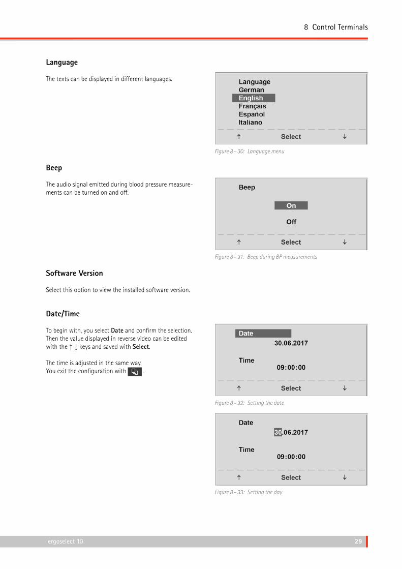
Language
The texts can be displayed in different languages.
Figure 8 – 30: Language menu
Beep
The audio signal emitted during blood pressure measure‑ments can be turned on and off.
Figure 8 – 31: Beep during BP measurements
Software Version
Select this option to view the installed software version.
Date/Time
To begin with, you select Date and confirm the selection. Then the value displayed in reverse video can be edited with the ↑ ↓ keys and saved with Select.
The time is adjusted in the same way. You exit the configuration with .
Figure 8 – 32: Setting the date
Figure 8 – 33: Setting the day

8 Control Terminals
30 ergoselect 10
EKG Type
The selected EKG Type determines the communication method with the ECG recorder, PC‑based ECG system, etc.
To prevent an accidental change of this setting, the menu is protected with a password. Using the arrow keys, enter 003 and confirm the entry with Select.
Figure 8 – 34: Entering the EKG Type password
All ergometers support the following communication modes:
• Analog with pulse Remote start mode; before advancing to the next load level, the ergometer generates a control pulse and sends the corresponding data via the interface.
• Analog / Digital An analog voltage controls the load – blood pressure measurements can be initiated with digital commands.
• Digital (default) The communication with the ergometer is entirely controlled with digital commands.
• Analog IN-OUT The entire communication (load control and BP mea‑surements) is controlled with analog signals. No digital data will be sent.
Select the communication mode and confirm with Select.
Figure 8 – 35: Selecting the ergometer communication mode
Note• The EKG Type needs to be selected only when the ergometer
is connected to an ECG unit. The selection is part of the installation procedure.
• The "Analog/Digital" and "Digital" communication is only possible when PC Mode is selected from the main menu or when this is the default mode.

8 Control Terminals
30 ergoselect 10 ergoselect 10 31
RPM
Here you determine the RPM limits. When these limits are exceeded, the LEDs for high or low speed (RPM) will illuminate.
Select the value to change (Min. or Max.) and confirm with Select.
Using the arrow keys, change the value and save the new value with Select.
Figure 8 – 36: Setting the RPM limit values
NoteThe limits selected in this menu only apply to the load range between 6 and 150 watts. At higher loads the RPM limits automatically adapt to the respective loads:
Load (watts) Green RPM range (1/min) 6 – 150 54 – 64 (adjustable) 151 – 250 58 – 65 251 – 350 68 – 75 351 – 450 78 – 85 451 – 550 88 – 95 551 – 650 98 – 105 651 – 750 108 – 115 751 – 850 118 – 125 851 – 950 > 125 951 – 999 > 130
Pulse Display
The pulse readout on the display can be turned off.
Figure 8 – 37: Setting the pulse readout

8 Control Terminals
32 ergoselect 10
8.3 Control Terminal T8.3.1 Turning the System On
You turn on the Couch Ergometer by pressing the power switch (toggle switch[ I / 0 ]).
Note• Instruct the patient not to pedal while the ergometer is
being turned on and during the selftest.
• Apply the blood pressure cuff to the patient AFTER the ergometer has been turned on and the selftest completed.
• The device can be configured to default to one of the operating modes. If this option is selected, the start screen of the selected operating mode (e.g., Ergometry) will be displayed instead of the main menu.
Figure 8 – 38: Control terminal T
The Couch Ergometer runs a self‑test. Subsequently, the main menu displays.
Figure 8 – 39: Selftest screen
The ergometer software is controlled from the touch panel.
Figure 8 – 40: Main menu

8 Control Terminals
32 ergoselect 10 ergoselect 10 33
8.3.2 Operating Modes with Control Terminal T
Couch Ergometers with control terminal T support the following operating modes:
PC Mode An external device (e.g., an ECG recorder, a PC‑based ECG system) controls the ergometer – no intervention at all is required at the Couch Ergometer. Figure 8 – 41: PC mode
Ergometry The Couch Ergometer runs an automatic exercise test – the available protocols (5 preconfigured, editable protocols and 5 user‑configurable protocols are saved in the ergometer (see section Settings on page 35).
Figure 8 – 42: Ergometry mode
Training / Test Ten user‑configurable training/test protocols are available (see section 8.3.2.3 Training / Test on page 37). A POLAR receiver is integrated in the couch ergometer and provides the relevant data for heart‑rate controlled training sessions. The test subject's performance can be assessed on the basis of these protocols.
Figure 8 – 43: Training/Test mode
Manual The couch ergometer is controlled manually, i.e., the user performs all load changes via the touch panel.
Figure 8 – 44: Manual mode
Setup Used to configure the Couch Ergometer.
Figure 8 – 45: Setup mode

8 Control Terminals
34 ergoselect 10
8.3.2.1 PC Mode
When the [ PC Mode ] key has been pressed, the screen appears as shown at right. The Couch Ergometer is waiting for commands from the external ECG unit.
As soon as the ergometer receives commands from the controlling ECG unit or PC, the exercise test will start and the corresponding values will be displayed.
The display shows heart rate (1/min), blood pressure (mmHg), oxygen saturation in percent (%), duration of the exercise test (min:ss), pedal speed (1/min) and current load (W).
The exercise test can only be terminated with the corre‑sponding command from the controlling ECG unit.
A blood pressure measurement can be initiated with the [ RR ] key. Pressing the [ RR ] key a second time during a measurement will stop the measurement.
Figure 8 – 46: PC mode screen
When you press the [ ECG ] key, the display will change. The acquired, electrical signals will be displayed. The amplitude (gain) can be adjusted with the arrow keys [ ] and [ ].
The pump for the electrode suction system can be switched on and off with the [ I / 0 ] key.
You can change the vacuum intensity between low, medium and high by touching the [ I / 0 ] key.
To switch off the pump, press the appropriate key [ low ], [ middle ], [ high ] for about 3 seconds.
Confirm all inputs with the [ ] key.
Figure 8 – 47: ECG screen

8 Control Terminals
34 ergoselect 10 ergoselect 10 35
8.3.2.2 Ergometry
Pressing the [ Ergometry ] key in the main menu activates the ergometry mode.
The different exercise test protocols will be displayed (5 preconfigured, editable and 5 user‑configurable proto‑cols).
All exercise test protocols (including the 5 preconfigured protocols) are editable.
Figure 8 – 48: Ergometry menu
Settings
When you touch a protocol, the available parameters will be displayed.
With the [ Edit ] key, you can modify each protocol para‑meter. The new inputs overwrite the existing values.
All protocols can be edited during operation (except for the PC mode).
To permanently save user‑programmed protocols, the [ Setup ] key in the main menu must be pressed (see Chap‑ter 8.3.2.5 Setup, Section Protocols on page 40).
Figure 8 – 49: Exercise test protocol – screen 1
In the configuration menu, the following parameters can be edited:
• the basic load (from 6 to 100 W),• the stage time (form 1 to 30 min),• the stage rate (increment, from 1 to 400 W).
Figure 8 – 50: Exercise test protocol – screen 2
8 Control Terminals
36 ergoselect 10
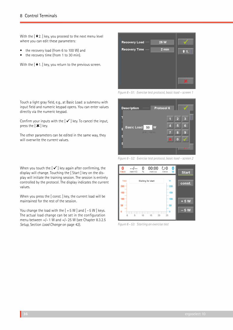
With the [ 2. ] key, you proceed to the next menu level where you can edit these parameters:
• the recovery load (from 6 to 100 W) and• the recovery time (from 1 to 30 min).
With the [ 1. ] key, you return to the previous screen.
Figure 8 – 51: Exercise test protocol, basic load – screen 1
Touch a light gray field, e.g., at Basic Load: a submenu with input field and numeric keypad opens. You can enter values directly via the numeric keypad.
Confirm your inputs with the [ ] key. To cancel the input, press the [ ] key.
The other parameters can be edited in the same way, they will overwrite the current values.
Figure 8 – 52: Exercise test protocol, basic load – screen 2
When you touch the [ ] key again after confirming, the display will change. Touching the [ Start ] key on the dis‑play will initiate the training session. The session is entirely controlled by the protocol. The display indicates the current values.
When you press the [ const. ] key, the current load will be maintained for the rest of the session.
You change the load with the [ + 5 W ] and [ – 5 W ] keys. The actual load change can be set in the configuration menu between +/– 1 W and +/– 25 W (see Chapter 8.3.2.5 Setup, Section Load Change on page 42). Figure 8 – 53: Starting an exercise test

8 Control Terminals
36 ergoselect 10 ergoselect 10 37
Terminating the Program
Once the full protocol has been completed, it terminates automatically.
The program can be terminated manually before the end of the protocol with [ Stop ]. First, you enter the recovery phase.
When you touch [ Stop ] again, the training will be termi‑nated.
Figure 8 – 54: Terminating an exercise – screen 1
Figure 8 – 55: Terminating an exercise – screen 2
8.3.2.3 Training / Test
Ten different protocols are available in the Training/Test menu.
To edit the protocol parameters, first touch the Training/Test protocol you want to edit.
Figure 8 – 56: Training/Test mode selected

8 Control Terminals
38 ergoselect 10
Then press the [ Edit ] key.
Figure 8 – 57: Editing the Training / Test protocol
The individual parameters (light gray fields) can now be edited by touching the display or by repeatedly tapping [ ]. If you need to input characters (numbers or letters), an (alpha‑) numeric keypad or a keyboard will be displayed.
The options for Type are [ Pulse ], [ Constant ], [ Interval ], [ Ramp Test ], [ PWC Test 1 ], [ PWC Test 2 ], [ PWC Test 3 ] and [ Inactive ]. You scroll through the Type options by tapping the [ ] key. Configure the parameters as required by the selected type.
Figure 8 – 58: Editing parameters – screen 1
With the [ ] key (arrow down, [ 2. ] or [ 3. ]), you access the next menu level where more parameters can be con‑figured. With the [ ] key (arrow up, [ 1. ] or [ 2. ]), you return to the previous screen.
Inputs are confirmed with the [ ] key.
Figure 8 – 59: Editing parameters – screen 2
8 Control Terminals
38 ergoselect 10 ergoselect 10 39
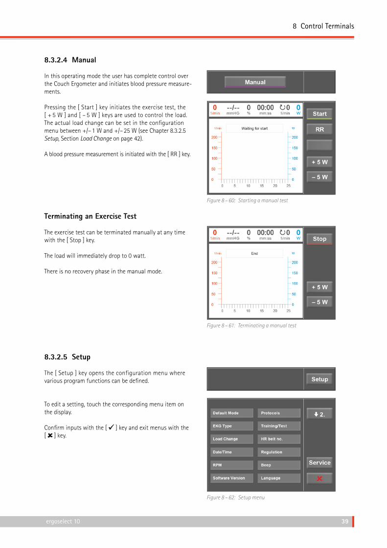
8.3.2.4 Manual
In this operating mode the user has complete control over the Couch Ergometer and initiates blood pressure measure‑ments.
Pressing the [ Start ] key initiates the exercise test, the [ + 5 W ] and [ – 5 W ] keys are used to control the load. The actual load change can be set in the configuration menu between +/– 1 W and +/– 25 W (see Chapter 8.3.2.5 Setup, Section Load Change on page 42).
A blood pressure measurement is initiated with the [ RR ] key.
Figure 8 – 60: Starting a manual test
Terminating an Exercise Test
The exercise test can be terminated manually at any time with the [ Stop ] key.
The load will immediately drop to 0 watt.
There is no recovery phase in the manual mode.
Figure 8 – 61: Terminating a manual test
8.3.2.5 Setup
The [ Setup ] key opens the configuration menu where various program functions can be defined.
To edit a setting, touch the corresponding menu item on the display.
Confirm inputs with the [ ] key and exit menus with the [ ] key.
Figure 8 – 62: Setup menu

8 Control Terminals
40 ergoselect 10
Default Mode
Select the operating mode to be activated when the couch ergometer is turned on:
• PC Mode• Ergometry• Training / Test• Manual
and confirm the selection with the [ ] key.
Figure 8 – 63: Default mode setup
Protocols
The first 5 exercise test protocols (WHO, BAL, Hollm, Std Fr and Standard) are preconfigured, but all protocols in the list are editable.
Figure 8 – 64: Setup – protocols, screen 1
To reach the level for editing of the individual protocol parameters, first touch the protocol that you want to modify (e.g., [ 5. Program 6 ]), and then touch the [ Edit ] key.
Figure 8 – 65: Setup – protocols, screen 2
To change the name of a protocol, touch the protocol name and enter the new name from the keypad. Confirm your inputs with the [ ] key.
Figure 8 – 66: Setup – protocols, screen 3

8 Control Terminals
40 ergoselect 10 ergoselect 10 41
At Type, you can choose [ Step ], [ Ramp ] or [ Inactive ]. You scroll through the Type options with the [ ] key.
When choosing the Step type (load increase in steps), define the basic load (from 6 to 100 W), the stage time (from 1 to 30 min) and the stage rate (increment, from 1 to 400 W). When choosing the Ramp type (continuous load increase), define the basic load (from 6 to 100 W) and the load increase (from 1 to 50 W).
Figure 8 – 67: Setup – protocols, screen 4
To configure the protocol parameters (light gray fields), touch one of the parameters. Edit the parameter as appropriate and confirm the modifi‑cation with the [ ] key.
Touch the Cancel key [ ] to conclude the parameter change.
With the [ 2. ] and [ 1. ] keys, you toggle between the different screens.
Figure 8 – 68: Setup – protocols, screen 5
EKG Type
The selected EKG Type determines the communication method with the ECG recorder, PC‑based ECG system, etc.
To prevent an accidental change, this setting is protected with a password.
A submenu opens when you touch EKG Type on the display. Enter the code number "3" via the numeric keypad and confirm with the [ ] key.
Figure 8 – 69: Setup menu

8 Control Terminals
42 ergoselect 10
The following communication modes are supported:
• Analog with pulse Remote start mode; before advancing to the next load level, the Couch Ergometer generates a control pulse and sends the corresponding data via the interface.
• Analog / Digital An analog voltage controls the load – blood pressure measurements can be initiated with digital commands.
• Digital (default) The communication with the couch ergometer is entirely controlled with digital commands.
• Analog IN-OUT The entire communication (load control and BP mea‑surements) is controlled with analog signals. No digital data will be sent.
Choose the appropriate communication mode and confirm with the [ ] key.
Figure 8 – 70: Setup – EKG Type
Load Change
With this function, you select the increments for load changes.
Figure 8 – 71: Load change setup

8 Control Terminals
42 ergoselect 10 ergoselect 10 43
Date/TimeTouch the respective fields to adjust date and time.
Enter day, month, year as well as hours, minutes and seconds via the numeric keypad.
Inputs are confirmed with the [ ] key.
Figure 8 – 72: Setup – date and time, screen 1
Figure 8 – 73: Setup – date and time, screen 2
Regulation
At Regulation, you can specify the load details, such as:
• load control (flat, normal, steep)• duration: load + (0 min to 15 min) and• duration load – (0 min to 15 min)
You scroll through the load control options (flat, normal, steep) by tapping the light gray text field.
Figure 8 – 74: Setup – regulation method, screen 1
When you touch the light gray fields to the right of 'Dura‑tion: load +' or 'Duration: load –', the time can be entered via the numeric keypad.
Inputs are confirmed with the [ ] key.
Figure 8 – 75: Setup – regulation method, screen 2

8 Control Terminals
44 ergoselect 10
RPM
In this menu, you determine the limits for the RPM indica‑tion.
The 3 LEDs on the control panel show the patient whether the pedal speed is high, low or correct.
Figure 8 – 76: Setup – RPM, screen 1
Touch the light gray field to the right of Min. or Max. and enter the value via the numeric keypad.
Confirm the input with the [ ] key or cancel the input with the [ ] key.
Figure 8 – 77: Setup – RPM, screen 2
Beep
A short beep confirms each key press. The audible feedback can be enabled and disabled.
Figure 8 – 78: Beep setup

8 Control Terminals
44 ergoselect 10 ergoselect 10 45
Software Version
This menu shows the software version and the date of the technical inspection of the measuring system (MTK).
Figure 8 – 79: Setup – software version
Language
Here you choose the language for the user interface.
Figure 8 – 80: Language setup
Display
Press the [ 2. ] key to display the next screen and touch Display.
Figure 8 – 81: Setup – screen display 1

8 Control Terminals
46 ergoselect 10
Switch the pulse readout on or off.
Select the blood pressure unit: mmHg (millimeter of mer‑cury) or kPa (kilopascal).
Figure 8 – 82: Setup – screen display 2

9 Cleaning, Maintenance, Disposal
46 ergoselect 10 ergoselect 10 47
9 Cleaning, Maintenance, Disposal9.1 General CleaningWipe the device surface down with a cloth moistened with soap water or a disinfectant.
The cloth should not be dripping wet; do not allow liquids to enter the device.
9.2 Cleaning the SaddleClean the saddle with a soft and dry or moist cloth. Disin-fectants used should not contain alcohol.
Warning• Shock Hazard •
• Disconnect the device from the power line before cleaning.
• Equipment Damage •• Do not allow liquids to enter the device.
Devices into which liquids have entered must be immediately cleaned and checked by a service technician, before they can be reused.
• Do not use acids, alkaline solutions (household cleaners) or caustic disinfectants.
9.3 DisinfectionThe following disinfectants are approved for disinfection:
Schülke & Mayr GmbH:• Antifect ® AF, FF, FD 10• Terralin ® (0.5 %)• Quartamon Med ®
B. Braun Melsungen AG:• Hexaquart plus ® (0.5 % / 5.0 %)• Hexaquart S ® (1.5 % / 5.0 %)• Meliseptol ®• Melsept SF ® (0.5 % / 5.0 %)
ECOLAB:• Incidin Foam ®
NoteDo not use cleaning agents or disinfectants that contain alcohol.
NoteStrictly observe the manufacturer's instructions for use.

9 Cleaning, Maintenance, Disposal
48 ergoselect 10
9.4 Cleaning the Blood Pressure Cuff9.4.1 Removing the Microphone
Pull the end of the cuff through the metal clasp and fold out the cuff.
Pull on the short Velcro tab to open the microphone pocket and carefully remove the microphone.
Figure 9 – 1: Removing the microphone
9.4.2 Cleaning
Clean the cuff and tubing with a moist cloth. You can use a dishwashing liquid or mild soap water (do NOT use cleaning agents containing alcohol).
Clean the microphone with a cloth moistened with alcohol or soap water.
Allow the microphone to dry before reinserting it in its pocket.
Warning• Equipment Damage •
• Cuff, microphone and tubing may not under any circumstances: — be immersed in liquid — be cleaned in a water bath or in running water.
9.4.3 Disinfection
For disinfection, spray a disinfectant sparingly on the cuff, the tubing and the microphone. After the contact time indicated by the manufacturer, wipe all components dry.
The following disinfectants are approved for disinfection:
Schülke & Mayr GmbH:• Antifect ® AF, FF, FD 10• Terralin ® (0.5 %)• Quartamon Med ®
B. Braun Melsungen AG:• Hexaquart plus ® (0.5 % / 5.0 %)• Hexaquart S ® (1.5 % / 5.0 %)• Meliseptol ®• Melsept SF ® (0.5 % / 5.0 %)
ECOLAB:• Incidin Foam ®
NoteStrictly observe the manufacturer's instructions for use.

9 Cleaning, Maintenance, Disposal
48 ergoselect 10 ergoselect 10 49
9.4.4 Inserting the Microphone
Slip the microphone into the pocket, the metal side facing the arm.
Guide the microphone cable out of the pocket and to the right of the Velcro tab. Then close the tab.
Fold the end of the cuff over and introduce it into the metal clasp.
Figure 9 – 2: Inserting the microphone
9.5 Maintenance9.5.1 Checks Before Each Use
Before each use, visually inspect the device for signs of mechanical damage. If you detect damage or impaired functions which may result in a hazard to the patient or the operator, the device must be repaired before it can be used again.
9.5.2 Technical Safety Inspections and Inspections of the Measuring System
The technical safety inspections and the inspections of the measuring system must be completed every two years according to the rules of the art by a Service Engineer authorized by ergoline GmbH.
Similarly, the automatic sphygmomanometer in the control terminal must be checked and, if necessary, calibrated by an authorized specialist every two years to fulfill legal requirements.
The date of the next inspection is indicated on the inspection sticker attached next to the type plate on the Couch Ergometer.
9.6 DisposalThe product described in this operator manual must not be disposed as unsorted municipal waste; it must be collected separately.
Please contact your authorized manufacturer ergoline GmbH for information concerning the disposal of your equipment. There is no waste disposal certificate. Proper disposal is documented by ergoline GmbH.Consult Operating Manual!

10 Technical Specifications
50 ergoselect 10
10 Technical Specifications10.1 ErgometerModel modular couch ergometer system ergoselect
Model ergoselect 10 M / P / T
Operating mode continuous operation
Power 90 – 264 V / 47 – 63 Hz / 200 VA max.fuses: 2 x T 2.5 AH
Braking principle computer‑controlled eddy current brake
Load range 6 – 450 W (optionally 1000 W), speed‑independent
Speed range 30 – 130 RPM
Load accuracy to DIN VDE 0750‑238
Load increments user‑configurable (control terminals P / T)
Internal protocols Control Terminal P:• 5 fixed and 5 user‑programmable exercise test protocols• manual load control
Control Terminal T:• 10 exercise test protocols (5 preconfigured, editable and
5 user‑configurable protocols)• 10 additional, user‑programmable training/exercise test
protocols• manual load control• 3 preprogrammed performance tests
Permitted patient weight 200 kg
Saddle adjustment motor‑assisted, continuous adjustment via remote control
Swivel range of the couch surface 0 – 45° continuous incline adjustment, motor‑driven via remote control
Crank length 170 mm
Displays Control Terminal T:TFT LCD, 165 x 104 mm, 800 x 480 pixels
Control Terminals M and P:LCD, 68 x 34 mm, 128 x 64 pixels
Interfaces RS‑232, USB Bluetooth (option) WLAN (option)
Dimensions, weight couch surface: 200 cm x 65 cm device: ca. 220 cm x 90 cm x 180 cm (L x W x H) in maximum tilt position weight: approx. 240 kg

10 Technical Specifications
50 ergoselect 10 ergoselect 10 51
Safety standards DIN EN 60601‑1, DIN EN 60601‑1‑2, DIN VDE 0750‑238
Protection class / degree of protection I / B (couch ergometer) BF (blood pressure module)
MDD classification class IIa to 93/42 EEC
RF emission class A to DIN EN 55011 (VDE 0875‑11) / 04/2011, DIN EN 60601‑1‑2
Environment operation:temperature: +10 to +40 °Crel. humidity: 30 to 75 %, no condensationatmospheric pressure: 800 to 1060 hPa
transport and storage:temperature: –20 to +70 °Crel. humidity: 10 to 95 %, no condensationatmospheric pressure: 500 to 1060 hPa
Type of protection IP 21
10.2 Blood Pressure Module
Measuring method auscultatory method (Korotkov), oscillometric; for resting BP, the results from both measurements are compared for plausibility
Measuring range systolic pressure: 40 to 280 mmHgdiastolic pressure: 40 to 280 mmHgpulse rate: 35 to 230 bpm
Measurement error, systematic systolic pressure: +/– 3 mmHgdiastolic pressure: +/– 3 mmHg(temperature: +15 to +25 °C)
Standard deviation (clinical trial) systolic/diastolic pressure: 7 mmHg (max.)
Inflation pressure 300 mmHg max.; during inflation the inflation pressure automatically adapts to patient's BP
Inflation rate between approx. 6 seconds (to 140 mmHg) and approx. 18 seconds (to 300 mmHg)
Max. cuff pressure 300 mmHg
Cuff deflation method pulse‑dependent deflation rateapprox. 3 mmHg/beat or approx. 3 mmHg/s
Calibration calibration with external pressure meter
Artifact rejection automatic artifact rejection and comparison of both mea‑suring methods for plausibility during measurement of the baseline pressure at rest

10 Technical Specifications
52 ergoselect 10
10.3 Exercise Test Protocols
Protocol Basic Load[W]
Stage Time[min]
Load Stage[W]
Recovery Load[W]
Recovery Time[min]
1. WHO 25 2 25 25 99
2. BAL 50 3 50 25 99
3. Hollmann 30 3 40 25 99
4. STD France 30 3 30 25 99
5. Standard 20 1 25 25 99
6. – 15. (user programmable) 25 2 25 25 99
Adjustment Range 20 – 100 1 – 30 1 – 400 20 – 100 (*) 1 – 99
(*) With Control Terminal P, the recovery load is fixed at 25 W.
10.4 Test Protocols (control terminal T only)
Protocol Basic Load[W]
Duration[sec]
Load Change[W]
Stage Time[sec]
Recovery Load[W]
Recovery Time[min]
Ramping protocol 0 120 25 10 25 99
PWC‑130 (*) 25 0 25 120 25 99
PWC‑150 (*) 50 0 25 120 25 99
PWC‑170 (*) 50 0 50 120 25 99
(*) the protocol advances to the recovery phase as soon as the target heart rate (130/150/170) is reached
10 Technical Specifications
52 ergoselect 10 ergoselect 10 53
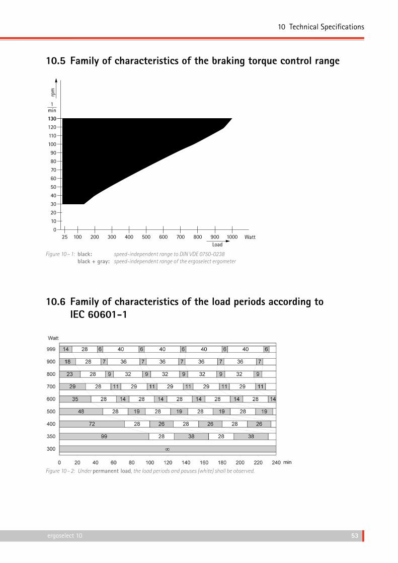
10.5 Family of characteristics of the braking torque control range
130130
120
110
100
90
80
70
60
50
40
30
20
10
0
1min
rpm
LoadWatt25 100 200 300 400 500 600 700 800 900 1000
Figure 10 – 1: black: speedindependent range to DIN VDE 07500238 black + gray: speedindependent range of the ergoselect ergometer
10.6 Family of characteristics of the load periods according to IEC 60601‑1
Figure 10 – 2: Under permanent load, the load periods and pauses (white) shall be observed.

11 Electromagnetic Compatibility EN 60601‑1‑2
54 ergoselect 10
11 Electromagnetic Compatibility EN 60601‑1‑2
Changes or modifications to this system not expressly approved by ergoline GmbH could cause EMC issues with this or other equipment.
This system is designed to comply with applicable regula‑tions regarding EMC.
Its compliance with these requirements has been verified. It needs to be installed and put into service according to the EMC information stated as follows.
Warning• RF Interference •
Use of portable phones or other radio frequency (RF) emitting equipment near the system may cause unexpected or adverse operation.
Caution• Equipment Malfunction •
The equipment or system should not be used adjacent to, or stacked with, other equipment. If adjacent or stacked use is necessary, the equipment or system should be tested to verify normal operation in the configuration in which it is being used.
Guidance and Manufacturer’s Declaration – Electromagnetic Emissions
The ergoselect ergometer is intended for use in the electromagnetic environment specified below. It is the responsibility of the customer or user to ensure that the ergoselect ergometer is used in such an environment.
Emissions Test Compliance Electromagnetic Environment – Guidance
RF emissions to EN 55011 Group 1 The ergoselect ergometer uses RF energy only for its internal function. Therefore, its RF emissions are very low and are not likely to cause any interference in nearby electronic equipment.
RF emissions to EN 55011 Class A The device characteristics determined by emissions allow the device to be used in industrial environments and in hospitals (CISPR 11, class A). When used in domestic surroundings (which normally requires com‑pliance with CISPR 11 class B), the device may not offer adequate protection for radio services. If required, the user may have to take remedial action by relocating or re‑orienting the device.
Harmonic emissions to EN 61000‑3‑2 Class A
Voltage fluctuations/flicker emissions to EN 61000‑3‑3
Complies

11 Electromagnetic Compatibility EN 60601‑1‑2
54 ergoselect 10 ergoselect 10 55
Guidance and Manufacturer’s Declaration – Electromagnetic Immunity
The ergoselect ergometer is intended for use in the electromagnetic environment specified below. It is the responsibility of the customer or user to ensure that the ergoselect ergometer is used in such an environment.
Immunity Test IEC 60601 Test Level Compliance Level Electromagnetic Environment – Guidance
Electrostatic discharge (ESD) to EN 61000‑4‑2
± 2 kV contact± 2 kV air± 4 kV air± 8 kV air± 15 kV air
± 2 kV passed± 15 kV passed
Floors should be wood, concrete or ceramic tile. If floors are covered with synthetic material, the relative humidity should be at least 30 %.
Electrical fast transient/burst to EN 61000‑4‑4
± 2 kV for power supply lines± 1 kV for input/output lines
± 2 kV passed Mains power should be that of a typical commercial or hospital environment.
Surge to EN 61000‑4‑5 ± 0.5 / 1 kV L‑N± 0.5 / 1 / 2 kV L‑PE± 0.5 / 1 / 2 kV N‑PE
± 1 kV passed± 2 kV passed± 2 kV passed
Mains power should be that of a typical commercial or hospital environment.
Voltage dips, short inter‑ruptions and voltage variations on power supply input lines to EN 61000‑4‑11
0 % / 0.5 cycle from 0° to 315° in 45° increments
passed Mains power should be that of a typical commercial or hospital environment. If the user of the ergoselect ergometer requires continued operation during power mains interruptions, it is recom‑mended that the ergoselect ergometer be powered from an uninterruptible power supply or a battery.
0 % / 1 cycle passed
70 % / 25 cycles passed
0 % / 250 cycles passed
Power frequency (50/60 Hz) magnetic field to EN 61000‑4‑8
30 A/m passed Power frequency magnetic fields should be at levels characteristic of a typical location in a typical commercial or hospi‑tal environment. The ergoselect ergometer has no com‑ponents susceptible to magnetic fields.
Note: UT is the a.c. mains voltage prior to application of the test level.

11 Electromagnetic Compatibility EN 60601‑1‑2
56 ergoselect 10
Guidance and Manufacturer’s Declaration – Electromagnetic Immunity
The ergoselect ergometer is intended for use in the electromagnetic environment specified below. It is the responsibility of the customer or user to ensure that the ergoselect ergometer is used in such an environment.
Immunity Test IEC 60601 Test Level Compliance Level Electromagnetic Environment – Guidance
Conducted RF to EN 61000‑4‑6 Radiated RF to EN 61000‑4‑3
3 Vrms 150 kHz to 80 MHz 3 V/m 80 MHz to 2.7 GHz
3 V 3 V/m
Portable and mobile RF communications equipment should be used no closer to any part of the ergoselect ergometer, including cables, than the recommended separation distance calculated from the equation applicable to the frequency of the transmitter.
Recommended separation distance:d = 1.2 √Pd = 1.2 √P for 80 MHz to 800 MHzd = 2.3 √P for 800 MHz to 2.5 GHz
where P is the maximum output power rating of the transmitter in watts (W) according to the transmitter manufac‑turer and d is the recommended separa‑tion distance in meters (m).
Field strengths from fixed RF transmit‑ters, as determined by an electromag‑netic site survey (a), should be less than the compliance level in each frequency range (b).
Interference may occur in the vicinity of equipment marked with the following symbol:
Note 1: At 80 MHz and 800 MHz, the higher frequency range applies.Note 2: These guidelines may not apply in all situations. Electromagnetic propagation is affected by absorption and reflection from structures,
objects, and people.
(a) Field strengths from fixed transmitters, such as base stations for radio (cellular/cordless) telephones and land mobile radio, amateur radio, AM and FM radio broadcast and TV broadcast cannot be predicted theoretically with accuracy. To assess the electromagnetic environment due to fixed RF transmitters, an electromagnetic site survey should be considered. If the measured field strength in the location in which the ergoselect ergometer is used exceeds the applicable RF compliance level above, the ergoselect ergometer should be observed to verify normal operation. If abnormal performance is observed, additional measures may be necessary, such as re‑orienting or relocating the ergoselect ergometer.
(b) Over the frequency range from 150 kHz to 80 MHz, field strengths should be less than 3 V/m.

11 Electromagnetic Compatibility EN 60601‑1‑2
56 ergoselect 10 ergoselect 10 57
Recommended separation distances between portable and mobile RF communications equipment and the ergoselect ergometer
The ergoselect ergometer is intended for use in an electromagnetic environment, as specified below, in which radiated RF disturbances are controlled. The customer or the user of the ergoselect ergometer can help prevent electromagnetic inter‑ference by maintaining a minimum distance between portable and mobile RF communications equipment (transmitters) and the ergoselect ergometer as recommended below, according to the maximum output power of the communications equipment.
Rated maximum output power of transmitter [W]
Separation distance according to frequency of transmitter in meters
150 kHz to 80 MHzd = 1.2 √P
80 MHz to 800 MHzd = 1.2 √P
800 MHz to 2.5 GHzd = 2.3 √P
0.01 0.12 0.12 0.23
0.1 0.37 0.37 0.74
1 1.17 1.17 2.33
10 3.7 3.7 7.37
100 11.7 11.7 23.3
For transmitters rated at a maximum output power not listed above, the recommended separation distance d in meters (m) can be estimated using the equation applicable to the frequency of the transmitter, where P is the maximum output power rating of the transmitter in watts (W) according to the transmitter manufacturer.
Note 1: At 80 MHz and 800 MHz, the higher frequency range applies.Note 2: These guidelines may not apply in all situations. Electromagnetic propagation is affected by absorption and reflection from structures,
objects, and people.

11 Electromagnetic Compatibility EN 60601‑1‑2
58 ergoselect 10
201000546000 • Version 2018‑10‑08 / Rev 01 • English


ergoline GmbHLindenstraße 572475 BitzGermany
Tel.: +49-(0) 7431 98 94 - 0Fax: +49-(0) 7431 98 94 - 128e-mail: [email protected]: www.ergoline.com


