
Ergonomic design of beverage can lift tabs based on numerical evaluations of fingertip discomfort
8
Applied Ergonomics 39 (2008) 150–157 Ergonomic design of beverage can lift tabs based on numerical evaluations of fingertip discomfort Jing Han a , Sadao Nishiyama b , Koetsu Yamazaki c, , Ryouiti Itoh a a Technology and Development Department, Universal Can Corporation, 1500 Suganuma, Oyama-Cho, Sunto-Gun, Shizuoka 410-1392, Japan b Universal Can Corporation, Sumitomofudosan-Korakuen Bld., Koishikawa 1-4-1, Bunkyo-ku, Tokyo 112-8525, Japan c Division of Innovative Technology and Science, Graduate School of Natural Science and Technology, Kanazawa University, Kakuma-machi, Kanazawa, Ishikawa 920-1192, Japan Received 20 December 2005; accepted 31 May 2007 Abstract This paper introduces finite element analyses to evaluate numerically and objectively the feelings in the fingertip when opening aluminum beverage cans, in order to design the shape of the tab. Experiments of indenting vertically the fingertip pulp by a probe and by tabs of aluminum beverage can ends have allowed us to observe force responses and feelings in the fingertip. It was found that a typical force–displacement curve may be simplified as a combination of three curves with different gradients. Participants feel a touch at Curve 1 of the force–displacement curve, then feel a pressure and their pulse at Curve 2, finally feel discomfort followed by a pain in the fingertip at Curve 3. Finite element analyses have been performed to simulate indenting the tab with the fingertip vertically to confirm that the simulation results agree well with the experimental observations. Finally, numerical simulations of the finger pulling up the tab of the can end has also been performed and discomfort in the fingertip has been related to the maximum value of the contact stress of the finger model. Comparisons of three designs of tab ring shape showed that the tab with a larger contact area with finger is better. r 2007 Elsevier Ltd. All rights reserved. Keywords: Human fingertip indentation experiments; Numerical evaluation of pain; Finite element analyses; Aluminum beverage cans 1. Introduction Structural optimization methods based on the finite element analysis (FEA) have been applied to search the optimum shape and dimensions of the aluminum beverage cans and bottles (Han et al., 2004, 2005; Yamazaki et al., 2007). With the quality of human life being improved, it is becoming necessary to design containers for universal use based on ergonomics evaluation that considers psycholo- gical, physiological, and anatomical affects. Ergonomics designs have been used in many applications (Kolich and Taboun, 2004; Hendrick, 2000). The physical, cognitive and emotional comfort of the consumers should be considered to create an optimal human–product interac- tion. However, to do this we need objective, measurable laboratory standards, which can be linked to subjective perceptions of comfort. Only in this way predictions can be made of whether a particular design will be felt comfor- table or not by the consumer. Easy-open cans with SOT (Stay-On-Tab) ends (Fig. 1) have been developed more than 30 years ago, and the functional problems such as the sealability and end openability have been almost solved (Nishiyama, 2002). Human-friendly ease-of-use and comfort are expected in the development of containers to enhance the quality of human life (Ueno, 2003). The finger-accessibility is used to evaluate whether it is easy to insert a fingertip into the gap between the ring and finger deboss of the can end, and whether it is painful or uncomfortable to pull up the tab ring. The more easily the finger can be inserted and the ring can be pulled up, the better the finger-accessibility is evaluated. To improve finger-accessibility, various methods have been developed. For example, deepening the finger deboss, curving up the ring, or applying scores to the panel under the tab so that the tab may float up a little when the ARTICLE IN PRESS www.elsevier.com/locate/apergo 0003-6870/$ - see front matter r 2007 Elsevier Ltd. All rights reserved. doi:10.1016/j.apergo.2007.05.010 Corresponding author. E-mail address: [email protected] (K. Yamazaki).
Transcript of Ergonomic design of beverage can lift tabs based on numerical evaluations of fingertip discomfort

ARTICLE IN PRESS
0003-6870/$ - se
doi:10.1016/j.ap
�CorrespondE-mail addr
Applied Ergonomics 39 (2008) 150–157
www.elsevier.com/locate/apergo
Ergonomic design of beverage can lift tabs based on numericalevaluations of fingertip discomfort
Jing Hana, Sadao Nishiyamab, Koetsu Yamazakic,�, Ryouiti Itoha
aTechnology and Development Department, Universal Can Corporation, 1500 Suganuma, Oyama-Cho, Sunto-Gun, Shizuoka 410-1392, JapanbUniversal Can Corporation, Sumitomofudosan-Korakuen Bld., Koishikawa 1-4-1, Bunkyo-ku, Tokyo 112-8525, Japan
cDivision of Innovative Technology and Science, Graduate School of Natural Science and Technology, Kanazawa University, Kakuma-machi,
Kanazawa, Ishikawa 920-1192, Japan
Received 20 December 2005; accepted 31 May 2007
Abstract
This paper introduces finite element analyses to evaluate numerically and objectively the feelings in the fingertip when opening
aluminum beverage cans, in order to design the shape of the tab. Experiments of indenting vertically the fingertip pulp by a probe and by
tabs of aluminum beverage can ends have allowed us to observe force responses and feelings in the fingertip. It was found that a typical
force–displacement curve may be simplified as a combination of three curves with different gradients. Participants feel a touch at Curve 1
of the force–displacement curve, then feel a pressure and their pulse at Curve 2, finally feel discomfort followed by a pain in the fingertip
at Curve 3. Finite element analyses have been performed to simulate indenting the tab with the fingertip vertically to confirm that the
simulation results agree well with the experimental observations. Finally, numerical simulations of the finger pulling up the tab of the can
end has also been performed and discomfort in the fingertip has been related to the maximum value of the contact stress of the finger
model. Comparisons of three designs of tab ring shape showed that the tab with a larger contact area with finger is better.
r 2007 Elsevier Ltd. All rights reserved.
Keywords: Human fingertip indentation experiments; Numerical evaluation of pain; Finite element analyses; Aluminum beverage cans
1. Introduction
Structural optimization methods based on the finiteelement analysis (FEA) have been applied to search theoptimum shape and dimensions of the aluminum beveragecans and bottles (Han et al., 2004, 2005; Yamazaki et al.,2007). With the quality of human life being improved, it isbecoming necessary to design containers for universal usebased on ergonomics evaluation that considers psycholo-gical, physiological, and anatomical affects. Ergonomicsdesigns have been used in many applications (Kolich andTaboun, 2004; Hendrick, 2000). The physical, cognitiveand emotional comfort of the consumers should beconsidered to create an optimal human–product interac-tion. However, to do this we need objective, measurablelaboratory standards, which can be linked to subjective
e front matter r 2007 Elsevier Ltd. All rights reserved.
ergo.2007.05.010
ing author.
ess: [email protected] (K. Yamazaki).
perceptions of comfort. Only in this way predictions can bemade of whether a particular design will be felt comfor-table or not by the consumer.Easy-open cans with SOT (Stay-On-Tab) ends (Fig. 1)
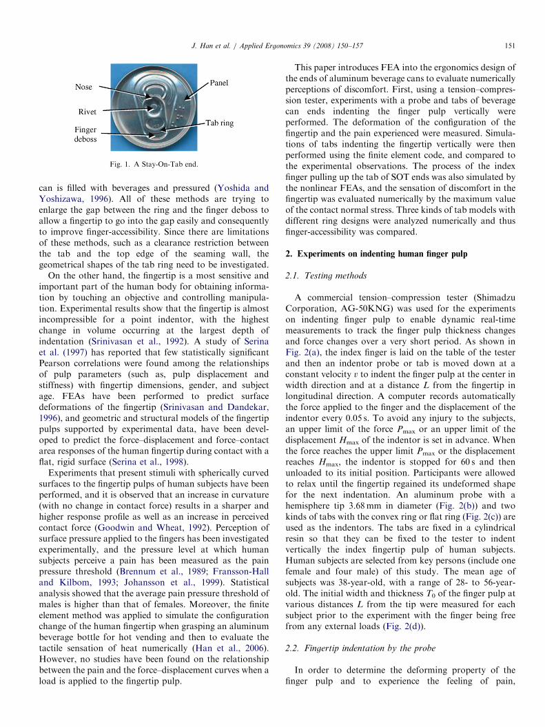
have been developed more than 30 years ago, and thefunctional problems such as the sealability and endopenability have been almost solved (Nishiyama, 2002).Human-friendly ease-of-use and comfort are expected inthe development of containers to enhance the quality ofhuman life (Ueno, 2003). The finger-accessibility is used toevaluate whether it is easy to insert a fingertip into the gapbetween the ring and finger deboss of the can end, andwhether it is painful or uncomfortable to pull up the tabring. The more easily the finger can be inserted and the ringcan be pulled up, the better the finger-accessibility isevaluated. To improve finger-accessibility, various methodshave been developed. For example, deepening the fingerdeboss, curving up the ring, or applying scores to the panelunder the tab so that the tab may float up a little when the
ARTICLE IN PRESS
Fig. 1. A Stay-On-Tab end.
J. Han et al. / Applied Ergonomics 39 (2008) 150–157 151
can is filled with beverages and pressured (Yoshida andYoshizawa, 1996). All of these methods are trying toenlarge the gap between the ring and the finger deboss toallow a fingertip to go into the gap easily and consequentlyto improve finger-accessibility. Since there are limitationsof these methods, such as a clearance restriction betweenthe tab and the top edge of the seaming wall, thegeometrical shapes of the tab ring need to be investigated.
On the other hand, the fingertip is a most sensitive andimportant part of the human body for obtaining informa-tion by touching an objective and controlling manipula-tion. Experimental results show that the fingertip is almostincompressible for a point indentor, with the highestchange in volume occurring at the largest depth ofindentation (Srinivasan et al., 1992). A study of Serinaet al. (1997) has reported that few statistically significantPearson correlations were found among the relationshipsof pulp parameters (such as, pulp displacement andstiffness) with fingertip dimensions, gender, and subjectage. FEAs have been performed to predict surfacedeformations of the fingertip (Srinivasan and Dandekar,1996), and geometric and structural models of the fingertippulps supported by experimental data, have been devel-oped to predict the force–displacement and force–contactarea responses of the human fingertip during contact with aflat, rigid surface (Serina et al., 1998).
Experiments that present stimuli with spherically curvedsurfaces to the fingertip pulps of human subjects have beenperformed, and it is observed that an increase in curvature(with no change in contact force) results in a sharper andhigher response profile as well as an increase in perceivedcontact force (Goodwin and Wheat, 1992). Perception ofsurface pressure applied to the fingers has been investigatedexperimentally, and the pressure level at which humansubjects perceive a pain has been measured as the painpressure threshold (Brennum et al., 1989; Fransson-Halland Kilbom, 1993; Johansson et al., 1999). Statisticalanalysis showed that the average pain pressure threshold ofmales is higher than that of females. Moreover, the finiteelement method was applied to simulate the configurationchange of the human fingertip when grasping an aluminumbeverage bottle for hot vending and then to evaluate thetactile sensation of heat numerically (Han et al., 2006).However, no studies have been found on the relationshipbetween the pain and the force–displacement curves when aload is applied to the fingertip pulp.
This paper introduces FEA into the ergonomics design ofthe ends of aluminum beverage cans to evaluate numericallyperceptions of discomfort. First, using a tension–compres-sion tester, experiments with a probe and tabs of beveragecan ends indenting the finger pulp vertically wereperformed. The deformation of the configuration of thefingertip and the pain experienced were measured. Simula-tions of tabs indenting the fingertip vertically were thenperformed using the finite element code, and compared tothe experimental observations. The process of the indexfinger pulling up the tab of SOT ends was also simulated bythe nonlinear FEAs, and the sensation of discomfort in thefingertip was evaluated numerically by the maximum valueof the contact normal stress. Three kinds of tab models withdifferent ring designs were analyzed numerically and thusfinger-accessibility was compared.
2. Experiments on indenting human finger pulp
2.1. Testing methods
A commercial tension–compression tester (ShimadzuCorporation, AG-50KNG) was used for the experimentson indenting finger pulp to enable dynamic real-timemeasurements to track the finger pulp thickness changesand force changes over a very short period. As shown inFig. 2(a), the index finger is laid on the table of the testerand then an indentor probe or tab is moved down at aconstant velocity v to indent the finger pulp at the center inwidth direction and at a distance L from the fingertip inlongitudinal direction. A computer records automaticallythe force applied to the finger and the displacement of theindentor every 0.05 s. To avoid any injury to the subjects,an upper limit of the force Pmax or an upper limit of thedisplacement Hmax of the indentor is set in advance. Whenthe force reaches the upper limit Pmax or the displacementreaches Hmax, the indentor is stopped for 60 s and thenunloaded to its initial position. Participants were allowedto relax until the fingertip regained its undeformed shapefor the next indentation. An aluminum probe with ahemisphere tip 3.68mm in diameter (Fig. 2(b)) and twokinds of tabs with the convex ring or flat ring (Fig. 2(c)) areused as the indentors. The tabs are fixed in a cylindricalresin so that they can be fixed to the tester to indentvertically the index fingertip pulp of human subjects.Human subjects are selected from key persons (include onefemale and four male) of this study. The mean age ofsubjects was 38-year-old, with a range of 28- to 56-year-old. The initial width and thickness T0 of the finger pulp atvarious distances L from the tip were measured for eachsubject prior to the experiment with the finger being freefrom any external loads (Fig. 2(d)).
2.2. Fingertip indentation by the probe
In order to determine the deforming property of thefinger pulp and to experience the feeling of pain,

ARTICLE IN PRESSJ. Han et al. / Applied Ergonomics 39 (2008) 150–157152
experiments on finger pulp indentation at L ¼ 7–8mm bythe probe were performed. Fig. 3 shows the force changeswith time and the displacement of the probe at velocities of
Fig. 2. Experimental setup: (a) fingertip and tab, (b) a probe, (c)
0 100 200 300 4000
2
4
6
Loa
d (N
)
Indenting time (sec)
Loading
Stopmoving
Unloading
Loa
d (N
)
Force V.S fiFing
Loa
d
DisplacemeForce V.S
Curve 1Touch
Curve Pressu
Fig. 3. Typical fingertip pulp compression results by the probe: (a) load–time cu
0 50 100 150 200 2500
2
4
6
8
10
Loa
d (N
)
Time (Sec)
v = 4 mm/min
HS1 HS2 HS3
v = 1 mm/min
HS1 HS2 HS3
Fig. 4. Observations of individual differences. Relation betw
v ¼ 1mm/min (Subject DM) as an example of measure-ment results. The force–time relation plotted in Fig. 3(a)shows that when keeping the probe unmoving after it
convex tab and flat tab, and (d) center cross-section of finger.
0.0 1.5 3.0 4.50
2
4
6
Indenting depth (mm)
Loading
Stopmoving
Unloading
nger thickness changeer thickness, Tf
nt of indenter, H displacement
2re
Curve 3Discomfort Pain
rves, (b) load–displacement curves, and (c) diagram of feelings in fingertip.
0 30
2
4
6
8
10
Loa
d (N
)
Indenting depth (mm)
v = 4 mm/min
HS1 HS2 HS3
v = 1 mm/min
HS1 HS2 HS3
1 2 4 5
een indenting (a) time and load and (b) depth and load.

ARTICLE IN PRESSJ. Han et al. / Applied Ergonomics 39 (2008) 150–157 153
reaches the upper limit Hmax, the indentation depths in thefinger does not change while the force decreases with time.This is the so-called stress relaxation due to the viscoelasticproperty of human fingers. A typical force–displacementcurve, as shown in Fig. 3(b), may be simplified as acombination of Curve 1, Curve 2 and Curve 3 as shown inFig. 3(c). Let us suppose Point A is the intersection ofCurve 1 and Curve 2, and Point B is the intersection ofCurve 2 and Curve 3. Note that the direction of thetransverse axis reverses if it presents the fingertip thicknessTf, calculated as Tf ¼ T0�H, where H is the indentationdepth, i.e., the displacement of the indentor. It wasobserved that the finger thickness decreased almost linearlyat low forces. After passing intersection Point A, the rate ofthickness decrease reduced and after Point B the thicknessdecreased almost linearly again but at an even lower rate ofdecrease. It is considered that when the deformation of softtissue approaches its limit, the force required to deform thesoft tissue becomes higher and higher. The experimentalresults agree with those in the literature (Serina et al.,1997).
Concerning the influence of the individual differencesand the indenting velocity of the probe, the experimentalresults of HS1 (Subject 1, in 30 s, female), HS2 (30 s, male)and HS3 (50 s, male) are compared in Fig. 4, when v ¼ 1and 4mm/min. Comparison of the results shows that thegradient of Curve 3 in the force–displacement plot does notchange much even though the finger dimensions aredifferent from person to person. The experimental resultsagree with those in the literature (Serina et al., 1997). Fig. 4also shows that the gradient of Curve 3 in the force–dis-
Fig. 5. Convex and flat tabs: (a) top view and (b) side view.
0.0 0.5 1.0 1.5 2.0 2.50
2
4
6
8
load
(N
)
Displacement (mm)
Flat tab, L = 2 mm
Flat tab, L = 5 mm
Fig. 6. Fingertip pulp compression results by tab loa
placement plot does not change much even though theindenting velocity changes. However, the slower thevelocity, the later the Curve 2 rises. It is because that ifthe velocity is lower, the indenting time becomes longer,hence, the resistance of the fingertip becomes smaller due tostress relaxation in the soft tissue.All participants were asked to report their feeling in their
fingertips during the indentation. The common feelingchanged as follows: they felt a touch at Curve 1 of theforce–displacement curve, then feel a pressure and theirpulse at Curve 2, finally feel discomfort followed by a painin the fingertip at Curve 3. The discomfort and pain in thefinger increased as the force or the indentation depthincreased. If the total load is the same, the narrower thecontact area, the deeper the indentation depth becomes,i.e., the thinner the fingertip becomes, hence, the greater thediscomfort and pain. In the numerical analysis of finger-accessibility of the tab described later, only Curve 3 isnecessary to be taken into account because we focus ononly the feeling of discomfort and pain in the fingertipwhen pulling up the tab to open the beverage can.Therefore, it is judged that the fingertip model can besimplified as an elastic model with a constant value ofYoung’s modulus.
2.3. Fingertip indentation by tabs
Since the space under the tab ring is narrow, the fingercannot be inserted much. Experiments on the tab indentingthe finger pulp vertically at L ¼ 2 and 5mm were
00 1 2 3
2
4
6
8
load
(N
)
Displacement (mm)
Flat tab L = 2 mm
Convex tab L = 2 mm
d. Effect of (a) pulp position and (b) tab shapes.
Fig. 7. Schematic diagram of finger: (a) vertical cross-section and
(b) transverse cross-section.

ARTICLE IN PRESSJ. Han et al. / Applied Ergonomics 39 (2008) 150–157154
performed. Two kinds of tabs with different tab ringdesigns, the convex ring and flat ring, as illustrated inFig. 5, were tested. Force–time–displacement curvesobtained when the velocity of the tab is v ¼ 2, 4 and6mm/min showed the same tendency as in the case of theprobe with a hemispherical tip.
Fig. 6(a) shows the influence of the indenting position inthe finger when indenting velocity was v ¼ 6mm/min(Subject CM). It is observed that Curve 2 in theforce–displacement curve rises earlier when L ¼ 2mm ascompared with the case of L ¼ 5mm because the fingertipis thinner at L ¼ 2mm. Fig. 6(b) shows the influence of thetab ring shape when indenting velocity was v ¼ 2mm/min(Subject DM). It was found that the deformation of fingerpulp indented by the flat tab was relatively small as
Fig. 8. Model of distal part of index finger: (a) vertical cross-section,
(b) transverse cross-section, and (c) finite element model.
Fig. 9. Analysis model.
4.5 5.0 5.5 6.0 6.5 7.0 7.5 8.0 8.50
1
2
3
4
5
6
Loa
d (N
)
Experiment (Round Tab)
0.0 0.5 1.0 1.5 2.0 2.5 3.0 3.5 4.0
0
1
2
3
4
5
6
FEM (Round Tab)
Loa
d (N
)
Finger thickness (mm)
Finger thickness (+ Ta mm)
Fig. 10. Comparison between analysis results and ex
compared with the case of indentation by the convex tab ifthe indenting force was the same.
3. Finite element analyses
3.1. Human fingertip model
Fig. 7 shows the schematic diagram of the distal part ofhuman fingertip (Netter, 2004). The fingertip was simplifiedas an elastic model with two kinds of mechanical proper-ties, the bone and the soft tissue. Fig. 8 shows the verticalcross-section, transverse cross-section and the whole modelof the three-dimensional finite element model of the finger.The mechanical properties of bone and soft tissue of indexfingertip model were assumed as: Young’s modulusE ¼ 17GPa, 5MPa, Poisson’s ratio n ¼ 0.3, 0.45, respec-tively (Wu et al., 2002; Fung, 1981). The model wasdescritized into eight-node solid elements. Since bonehardly deforms during pulling up the tab, only one layerof elements was defined as bone in order to savecomputational costs.
3.2. Simulation of the tab indenting the fingertip
In order to confirm the effectiveness of the finite elementmodel of the fingertip for numerical analyses of finger-accessibility, simulations of the tab indenting vertically thefinger pulp vertically at L ¼ 2mm (Fig. 9) were performedand compared with the experimental results. The length ofthe finger model was shortened and the bone elements wereneglected to save computational costs. The freedoms of thenodes adjacent to the bone were fixed. The tab ring wasassumed to be a rigid body in the finger indentingsimulation. The finite element code, MSC.MARC wasutilized to perform the numerical analyses.Experimental results and numerical analysis results are
compared in Fig. 10. The upper curve shows the thicknessof the finger model at the indentation position obtained by
4.5 5.0 5.5 6.0 6.5 7.0 7.5 8.0 8.50
1
2
3
4
5
6
Experiment (Flat Tab)
0.0 0.5 1.0 1.5 2.0 2.5 3.0 3.5 4.0
0
1
2
3
4
5
6
FEM (Flat Tab)
Finger thickness (mm)
Finger thickness (+ Ta mm)
perimental ones: (a) round tab and (b) flat tab.

ARTICLE IN PRESS
Fig. 13. Finite element analysis model.
J. Han et al. / Applied Ergonomics 39 (2008) 150–157 155
numerical analysis with the thickness noted as Ta when thedeformation depth in the finger model is 1.25mm. Thelower curve shows the finger thickness measured in theexperiments. Since the initial finger thickness of SubjectDM at L ¼ 2mm was 8.19mm, the force–displacementcurves in Fig. 6(b) could be translated into force–thicknesscurves. Comparing the analysis results with the experimentresults, it is clear that the first part of the force–thicknesscurves agree very well with each other. Therefore, it can beconcluded that the finite element model of the finger can beused by finger-accessibility analysis to evaluate discomfortnumerically in the fingertip. Fig. 11 also shows thatdeformation in the finger model compressed by the flattab model was relatively small as compared with theconvex tab model when the load was the same, whichagrees with the experimental observations.
4. Numerical analysis of finger-accessibility
4.1. Analysis model
Fig. 12 shows the standard opening method of thebeverage can with an SOT end (Reynolds Metals Com-pany, 1984). Although there are various methods ofopening the beverage can by consumers, this paper focuson this standard opening method. There are four steps, thefirst step is to pull up the tab ring using the index fingerwhile pressing the tab nose with the thumb. The secondstep is to pull the tab completely forward and the third stepis to push the tab back down. The can is ready for drinkingwhen the tab stays on the can as shown in the last step. Inthe first step, pressing the tab nose by the thumb can make
Forc
e (N
)
Displacement (mm)
Convex tab
Flat tab6
4
2
00.5 1.0 1.5
Fig. 11. Simulation results.
Fig. 12. SOT end opening procedures: (a) ste
the tab ring rise up a little naturally and can prevent the tabring slipping down the surface of the index finger pulp sothat the finger can be easily inserted into the space underthe tab ring. To evaluate the feeling of the pain (ordiscomfort) in the finger when pulling up the tab ring, aFEA model was developed as shown in Fig. 13. Assumingthe deformations of tabs and the finger models aresymmetrical to the central vertical plane, numericalanalyses on 1/2 finite element model was performed. Allfreedoms of the nodes on the circular edge of the rivet partof the tab were fixed. The edge nodes of the bone elementson the tip of the finger model were enforced to move0.5mm forward and then move up and forward to simulatethe process of a fingertip pulling up the tab. The maximumvalue of the contact normal stress of the finger model whenpulling up the tab was used to represent the pain(discomfort) in the finger. The smaller the contact stress
p 1, (b) step 2, (c) step 3, and (d) step 4.
Fig. 14. Finite element models of tabs: (a) Model 1, (b) Model 2, and
(c) Model 3.

ARTICLE IN PRESS
Fig. 15. Contact normal stress distributions of finger models: (a) Model 1, (b) Model 2, and (c) Model 3.
1
0.85
0.90
0.95
1.00
1.05
1.10
1.15
1.20
ratio
Tab Model No.
Maximum value of contact normal stress of finger
Contact areas of finger
Maximum value of equivalent strain of finger
2 3
Fig. 16. Comparison of three tab models.
J. Han et al. / Applied Ergonomics 39 (2008) 150–157156
is, the less pain (discomfort) the finger experiences and thebetter the finger-accessibility of the tab was evaluated.
The material model used for the aluminum tab isassumed as an elasto-plastic von Mises material withisotropic hardening. The Young’s modulus E ¼ 70GPa,Poisson’s ratio n ¼ 0.33 and yielding stress s ¼ 260MPawere assumed. The tab model was descritized into four-node shell elements with 0.33mm thickness.
4.2. Comparison of the finger-accessibility of tab ring
designs
In order to investigate the effect of the geometric shapeof the tab ring, three kinds of shape designs, i.e., the convexring (Model 1), the flat ring (Model 2) and the concave ring(Model 3), were modeled as shown in Fig. 14. The tab ringof Model 3 is designed to match the shape of finger pulp.The length of the symmetric central lines and thesymmetric central cross-sections of three tab models werethe same.
Fig. 14 shows the deformation of the fingertip pulp andthe contact normal stress distribution of finger model whenthe tab models were pulled up 2.5mm. It is obvious that thestress concentration occurred at the part in contact with thecentral part of the convex ring. When the displacement ofthe ring center (H1) reached 2.5mm, the finger can beinserted more and the tab can be re-held for easy opening.The difficulty was evaluated as can openability rather thanfinger-accessibility when H1 is larger than 2.5mm, so thesimulation results before H1 reaches 2.5mm were observed.The maximum value of the contact normal stress, thecontact areas, and the maximum value of the equivalentelastic strain of the finger were compared in Fig. 15for three tab models when H1 ¼ 2.5mm. In the case of thetab with a concave ring, the contact area between thefinger and the ring was the largest and the maximumvalue of the contact normal stress and equivalent strainwere the smallest. It is considered that if a larger areashares the load required for pulling up the tab, thecontact normal stress and equivalent strain may becomelower. Hence, the pain in the finger may decrease more.Therefore, it is concluded that the finger-accessibility of thetab with a larger contact area with finger is better.The finger-accessibility of the tab with a concave ring isbetter than that of the tab with a flat ring or a convexring (Fig. 16).
5. Conclusions
Experiments of indenting the fingertip pulp vertically bya probe and the tab of can ends were performed to observeforce responses and to study feelings in the fingertip.A FEA was performed to simulate the tab indenting thefingertip vertically for developing the finite element modelof the fingertip. Moreover, a numerical simulation of afinger lifting up the tab of can end may also be performed,and discomfort in the fingertip evaluated numerically topresent the finger-accessibility of the tab. The comparisonof three tab shape designs showed that the finger-accessibility of the tab that had a larger contact area withfinger is better.
References
Brennum, J., Kjeldsen, M., Jensen, K., Staehelin, J.T., 1989. Measure-
ments of human pressure-pain threshold on fingers and toes. Pain 38,
211–217.
Fransson-Hall, C., Kilbom, A., 1993. Sensitivity of the hand to surface
pressure. Appl. Ergon. 24, 181–189.
Fung, Y.C., 1981. Biomechanics: Mechanical Properties of Living Tissues.
Springer.
Goodwin, A.W., Wheat, H.E., 1992. Magnitude estimation of contact
force when objects with different shapes are applied passively to the
fingerpad. Somatosens. Motor Res. 9–4, 339–344.

ARTICLE IN PRESSJ. Han et al. / Applied Ergonomics 39 (2008) 150–157 157
Han, J., Yamazaki, K., Nishiyama, S., 2004. Optimization of the crushing
characteristics of triangulated aluminum beverage cans. Struct.
Multidisciplinary Optim. 28–1, 47–54.
Han, J., Itoh, R., Nishiyama, S., Yamazaki, K., 2005. Application of
structure optimization technique to aluminum beverage bottle design.
Struct. Multidisciplinary Optim. 29–4, 304–311.
Han, J., Yamazaki, K., Itoh, R., Nishiyama, S., 2006. Multi-objective
optimization of a two-piece aluminum beverage bottle considering
tactile sensation of heat and embossing formability. Struct. Multi-
disciplinary Optim. 32–2, 141–151.
Hendrick, W., 2000. The technology of ergonomics. Theor. Issues Ergon.
Sci. 1 (1), 22–33.
Johansson, L., Kjellberg, A., Kilbom, A., Hagg, G., 1999. Perception of
surface pressure applied to the hand. Ergonomics 42–10, 1274–1282.
Kolich, M., Taboun, S.M., 2004. Ergonomics modelling and evaluation of
automobile seat comfort. Ergonomics 47 (8), 841–863.
Netter, H.F., 2004. Atlas of Human Anatomy, third ed. Nankodo Co.,
Ltd. Japanese version, p. 454.
Nishiyama, S., 2002. Aluminum can recycling in a synthesized closed-
loop. Corros. Eng. 51, 381–394.
Reynolds Metals Company, Aluminum Can Division, 1984. Stay-on-Tab
pamphlet.
Serina, E., Mote Jr., D., Rempel, D., 1997. Force response of the fingertip
pulp to repeated compression—effects of loading rate, loading angle
and anthropometry. J. Biomech. 30–10, 1035–1040.
Serina, E., Mockensturm, E., Mote Jr., D., Rempel, D., 1998. A structural
model of the forced compression of the fingertip pulp. J. Biomech. 31,
639–646.
Srinivasan, M., Dandekar, K., 1996. An investigation of the mechanics of
tactile sense using two-dimensional models of the primate fingertip.
Trans. ASME J. Biomech. Eng. 118, 48–55.
Srinivasan, M., Gulati, J., Dandekar, K., 1992. In vivo compressibility
of the human fingertip. Trans. ASME Adv. Biomech. Eng. 22,
573–576.
Ueno, H., 2003. Drinks cans with customer convenience. In: Proceedings
of the Canmaker Summit, Singapore, in CD-ROM.
Wu, J.Z., Dong, R.G., Rakheja, S., Schopper, A.W., 2002. Simulation of
mechanical responses of fingertip to dynamic loading. Med. Eng. Phys.
24, 253–264.
Yamazaki, K., Itoh, R., Watanabe, M., Han, J., Nishiyama, S.,
2007. Applications of structural optimization techniques in light
weighting of aluminum beverage can ends. J. Food Eng. 81,
341–346.
Yoshida, M., Yoshizawa, T., 1996. Japan Utility Model No. 2508637.