
ERACS.C-N COOLING HEATING HOT WATER Higher efficiency air ...
20
ELITE TM Series Cooling Capacity:252~1341 kW (72~381 Tons) Heating Capacity:260~1363 kW (74~388 Tons) HEATING COOLING HOT WATER ERACS.C-N Higher efficiency air-cooled screw pump
Transcript of ERACS.C-N COOLING HEATING HOT WATER Higher efficiency air ...

ELITETM Series
Cooling Capacity:252~1341 kW (72~381 Tons)Heating Capacity:260~1363 kW (74~388 Tons)
HEATINGCOOLING HOT WATER
ERACS.C-NHigher efficiency air-cooled screw pump

2
High Efficiency Air-cooled Heat Pump
Unit Classification
Operation Range
The latest CLIMAVENETA "ERACS.C-N" series high efficiency screw heat pump is totally imported from Italy and it's energy efficiency can fully reach Class A of European standard and Energy Saving Certificate of Chinese national code. For all units of air-cooled heat pump, the 4-way valve is equipped to reverse the circulation direction of refrigerant that can offer chilled water or hot water to users.
Because the unit is air source heat pump and using the reverse cycle, the cooling tower, cooled water pump and cooled water system can de deleted that the investment and operation charge of cooled system can be reduced. And the unit can be installed on the building roof or outside, no need extra room. So the ERACS.C-N units suit for all commercial and industry application and can fulfill the air-conditioning and heating request all year round.The unit adopts Intelligent defrost programme to ensure safe operation and stable heating in winter.The environment friendly refrigerant HFC134a is used for better running efficiency and the temperature tolerance in summer and hot water temperature in winter are both higher.
ERACS2222C-N-D-Bmeans high efficiency screw heat pump unit using R134a with partial heat recovery function and unit model is 2222.
Suggested Workplace
B Standard unit suitable for normal placeSL Super low noise unit suitable for the place where have strict noise requirement
Nomenclature
ERACS 2222 C - N - D - SL
Configuration: B standard SL super low noiseHeat Recovery: D partial heat recoveryFunctions: chiller is not markedN heat pump unitDesign numberModelAir-cooled Screw Heat Pump
Cooling
Tube and shell type heat exchanger (Evaporator)
Fin type heat exchanger (Condenser)
Heating
Tube and shell type heat exchanger (Evaporator)
Fin type heat exchanger (Condenser)
Water outlet Temp. (during running) ℃ Air inlet Temp.℃
Max Temp.
15℃
-
55℃(60℃as optional)
-
Max Temp.
-
46℃
-
20℃
Min Temp.
5℃
-
26℃
-
Min Temp.
-
-10℃
-
-10℃

Unit Features
3
Screw Type Compressor● Semi-hermetic screw compressor specially designed for HFC134a with higher compression efficiency under full load as well as part load; ● Precisely manufactured twin-screw rotor with aircraft-grade bear featuring in high reliability, low noise, low vibration and stable running;● The motor drive the bear directly with least moving component and wearing part that cause no energy loss and higher mechanical efficiency;● Automatically adjust power output according to load by microprocessor. The slide valve is fixed for stepless control and increase part load performance.
Energy Saving and Environment FriendlyAll units of ERACS.C-N series can reach Class A according to European energy efficiency standard and Chinese energy saving standard.
Heating in Super Low Temp.Super heat exchanger with injecting cooling and intelligent defrost technology to make sure heating even in -10℃. So the balance between reliability and COP of heating in super low temp. is perfectly achieved.
Innovative Intelligent Defrost Function (CLIMAVENETA Patent)The reverse cycle type intelligent defrost function introduce the self-adjust technology which can automatically modify and regulate the judgement and data for next defrosting according to the change of ambient air temperature, humidity and defrost time as well as the difficult level of last defrosting. So the defrost no longer need manual adjusting and it can be fit for all kinds of weather condition.
Much precise, reliable and energy saving from traditional defrosting method.
AB
CD
EF
G

4
High Efficiency Air-cooled Heat Pump
Unit FeaturesElectric Expansion Valve● EEV for precise control to meet load change.
Green Technology● Environment friendly HFC134a;● Optimize the refrigerant system to reduce energy consumption and CO2 emission.
High Performance FanHigh efficiency exterior rotor fan from German brand with variable speed controller. It can change fan speed automatically (DVV design) to reduce energy consumption and fan noise.
Super Low NoiseAll compressors of ERACS.C-N series are equipped inside the sound proof housing. And the compressor is installed on the spring isolator. The rubber pad is also fixed between compressor and frame to prevent vibration and noise. The fan is exclusive designed with aircraft grade blades and aluminum-cast exterior motor as well as the air deflector cylinder to eliminate air side noise.
According to different noise request in different application, the super low noise unit also can be installed.The noise of super low noise unit (SL) is 8-10 dB(A) lower than standard unit (B).
Build-in pump and hydraulic kitThe build-in water pump (available in different head) or hydraulic kit can be selected for the unit. The hydraulic kit includes all necessary kits such as strainer, pump, safety valve, pressure gauge, pressure difference switch, stop valve and pump control system.
Customer can simplify the installation on site, save installation area and increase auto-control level by selecting build-in kits.
Reliable OperationThe unit is designed, manufactured, tested according to international and local standard AHRI, EN, UNI, JIS, GB/T18430.1 for reliable performance. And the electrical system is also strictly designed and produced comply with standard IEC60204-1/GB5226.1. The unit is controlled by the dedicated microprocessor control system. In order to protect operation safety, the high/low pressure switch, over/under voltage, phase failure, phase reverse, over load, winding over heat, gas exhaust temperature, water flow switch and oil heater are all equipped.
For the evaporator, the heater is attached to the evaporator exterior to prevent freezing.
Heat Recovery-Hot water free!The heat of condensation usually will be exhaust to the environment during air-cooled heat pump working in cooling. And also the unit can not transfer all the heat during heating. So CLIMAVENETA introduce the heat recovery technology which can recovery the condensation heat during cooling and extra heat during heating to produce free hot water. This technology will help users to save obvious operation cost.
Optional Function● Available optional function: low temperature refrigeration, ice storage, fin protection, salt spray protection of fins, remote
keyboard, power factor regulation.
Dedicated EconomizerThe dedicated economizer is equipped for all units to increase heat exchange and supercooling. Finally enhance working performance and efficiency.

5
Latest Control SystemAll unit are equipped with latest control system, friendly human-computer interface for excellent control performance, better
extended function, regulation ability and compatibility.
Friendly Interface● New generation regulation system with human-
computer interface, better extended utility, supervision and
compatibility.
● Panel screen on the unit, easy operation, better
protection Microprocessor regulation fulfill human-free
running.
● W3000 with LCD display, multi-language & multilevel
menu for data display & set-point regulation .
According to CLIMAVENETA tradition, another display of
compressor’ working data is adopted for easy supervision.
Unit Control and Operation Regulation ● Dedicated W3000 microprocessor is inserted with CLIMAVENETA control algorithm to make sure energy saving and reliability.
● FIFO compressor running time balance function extends unit’ working life;
● Auto compressor power input control following with load change from 10-100% for energy saving;
● Environment adaptation by data regulation and setting;
● Modulating measurement is used for temperature pressure protection. It can increase reliability and predict fault occurs.
● Expansion kit for remote control and group control.
Network Communication and BMS Control● Available in BMS control, such as CLIMAVENETA or De'longhi control system, as well as ModBus, LonWorks, BacNet, Siemens
and Trend BMS control system.
Fault Predict, Alarm and Diagnose● Microprocessor have complete fault predict, alarm, record and self
diagnose function assuring operation protection & working state.
● “Black Box” record 400 faults and 200 data before each fault, which
diagnose & remove fault quickly
● We also can find potential fault and take preventive action before it
occur by CLIMAVENETA remote service program
6
High Efficiency Air-cooled Heat Pump
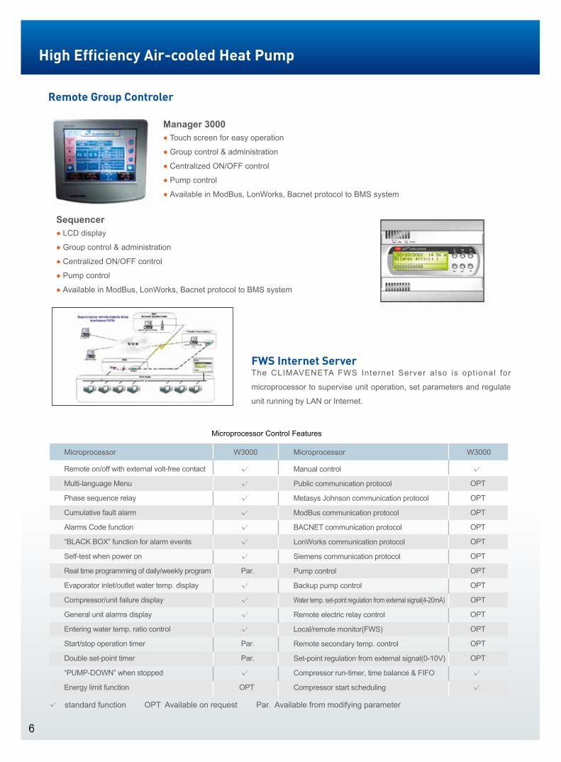
Remote Group Controler
Manager 3000● Touch screen for easy operation
● Group control & administration
● Centralized ON/OFF control
● Pump control
● Available in ModBus, LonWorks, Bacnet protocol to BMS system
Sequencer● LCD display
● Group control & administration
● Centralized ON/OFF control
● Pump control
● Available in ModBus, LonWorks, Bacnet protocol to BMS system
FWS Internet ServerThe CLIMAVENETA FWS Internet Server also is optional for
microprocessor to supervise unit operation, set parameters and regulate
unit running by LAN or Internet.
√ standard function OPT Available on request Par. Available from modifying parameter
W3000
Microprocessor Control Features
Manual control
Public communication protocol
Metasys Johnson communication protocol
ModBus communication protocol
BACNET communication protocol
LonWorks communication protocol
Siemens communication protocol
Pump control
Backup pump control
Water temp. set-point regulation from external signal(4-20mA)
Remote electric relay control
Local/remote monitor(FWS)
Remote secondary temp. control
Set-point regulation from external signal(0-10V)
Compressor run-timer, time balance & FIFO
Compressor start scheduling
Microprocessor
Remote on/off with external volt-free contact
Multi-language Menu
Phase sequence relay
Cumulative fault alarm
Alarms Code function
“BLACK BOX” function for alarm events
Self-test when power on
Real time programming of daily/weekly program
Evaporator inlet/outlet water temp. display
Compressor/unit failure display
General unit alarms display
Entering water temp. ratio control
Start/stop operation timer
Double set-point timer
“PUMP-DOWN” when stopped
Energy limit function
Microprocessor
√
√
√
√
√
√
√
Par.
√
√
√
√
Par.
Par.
√
OPT
W3000
√
OPT
OPT
OPT
OPT
OPT
OPT
OPT
OPT
OPT
OPT
OPT
OPT
OPT
√
√

7
S t a n d a r d Ve r s i o n
(1) Chilled water (in/out) 12/7℃
Ambient temperature 35℃
(2) Condenser water (in/out) 40/45℃
Ambient temperature 7℃
Relative humidity 87%
(3) Partial heat recovery water (in/out) 40/45℃
Note: The partial heat recovery parameter during heating is same as the partial heat recovery parameter during cooling.
kW
kW
m3/h
kPa
kW
kW
m3/h
kPa
kW
kW
m3/h
kPa
kW
m3/h
kPa
m3/s
kW
kg
kg
mm
mm
mm
kg
Cooling capacity (1)
Power input (1)
Evaporator water flow rate (1)
Evaporator water pressure drop (1)
Heating capacity (2)
Power input (2)
Hot water flow rate (2)
Hot water pressure drop (2)
Cooling capacity (1)
Power input (1)
Evaporator water flow rate (1)
Evaporator water pressure drop (1)
Partial heat recovery (1)(3)
Partial heat recovery water flow rate (1)(3)
Partial heat recovery water pressure drop (1)(3)
Cooling
Heating
Cooling
Heating
ERACS.C-N-D
Microprocessor
Compressors
Number of compressors
Number of circuit
Capacity regulating
Fans
Number of fans
Refrigerant charge
Refrigerant R134a
Oil
Dimension
Length
Width
Height
Operating weight
Model
Air flow rate
Fan power
ERACS.C-N
B
W3000
25 ~ 100% 12.5 ~ 100%
General Technical Data
1201
252.0
66.7
43.4
27.1
260.1
67.3
45.2
29.4
261.5
64.3
45.0
29.1
59.5
10.3
47.4
1
1
6
34.8
2.0
77
22
4000
2260
2430
3590
1421
340.0
93.2
58.5
33.6
360.4
93.2
62.6
38.4
352.7
90.0
60.7
36.1
83.2
14.5
52.1
1
1
6
35.3
2.0
95
22
4900
2260
2430
4480
1801
440.0
114.5
75.7
35.7
447.5
113.7
77.8
37.7
456.5
110.5
78.5
38.4
102.2
17.8
50.1
1
1
10
52.8
2.0
105
35
4900
2260
2430
5200
2101
500.0
132.5
86.1
46.2
519.1
133.7
90.2
50.7
518.8
127.9
89.2
49.6
118.3
20.6
49.4
1
1
10
55.7
2.0
125
35
5800
2260
2430
5860
2401
565.0
150.0
97.3
35.0
582.6
149.5
101.2
37.9
586.2
144.7
100.8
37.6
133.9
23.3
41.8
1
1
12
63.4
2.0
140
35
5800
2260
2430
6130
2022
510.1
139.2
87.8
38.6
521.9
132.7
90.7
41.1
529.2
134.3
91.0
41.5
124.3
21.6
34.9
2
2
10
50.6
38.1
2
1.2
171
44
4900
2260
2430
6050
2422
596.9
161.7
102.8
48.6
614.0
157.5
106.7
52.4
619.3
156.1
106.5
52.2
144.4
25.1
47.1
2
2
12
61.0
46.0
2
1.2
198
44
5800
2260
2430
6710
2222
558.2
150.0
96.1
42.5
577.3
146.0
100.3
46.3
579.1
144.7
99.6
45.6
133.9
23.3
40.5
2
2
12
65.6
50.6
2
1.2
191
44
5800
2260
2430
6630

8
High Efficiency Air-cooled Heat Pump
S t a n d a r d Ve r s i o n
(1) Chilled water (in/out) 12/7℃
Ambient temperature 35℃
(2) Condenser water (in/out) 40/45℃
Ambient temperature 7℃
Relative humidity 87%
(3) Partial heat recovery water (in/out) 40/45℃
Note: The partial heat recovery parameter during heating is same as the partial heat recovery parameter during cooling.
kW
kW
m3/h
kPa
kW
kW
m3/h
kPa
kW
kW
m3/h
kPa
kW
m3/h
kPa
m3/s
m3/s
kW
kW
kg
kg
mm
mm
mm
kg
Cooling capacity (1)
Power input (1)
Evaporator water flow rate (1)
Evaporator water pressure drop (1)
Heating capacity (2)
Power input (2)
Hot water flow rate (2)
Hot water pressure drop (2)
Cooling capacity (1)
Power input (1)
Evaporator water flow rate (1)
Evaporator water pressure drop (1)
Partial heat recovery (1)(3)
Partial heat recovery water flow rate (1)(3)
Partial heat recovery water pressure drop (1)(3)
Cooling
Heating
Cooling
Heating
ERACS.C-N-D
Microprocessor
Compressors
Number of compressors
Number of circuit
Capacity regulating
Fans
Number of fans
Refrigerant charge
Refrigerant R134a
Oil
Dimension
Length
Width
Height
Operating weight
Model
Air flow rate
Fan power
ERACS.C-N
B
W3000
12.5 ~ 100%
General Technical Data
5422
1340.9
397.0
230.8
50.6
1363.0
370.0
236.9
53.3
1391.2
383.1
239.2
54.4
354.4
61.6
40.6
2
2
24
122.0
92.1
2
1.2
400
70
11800
2260
2430
11870
4822
1290.2
346.1
222.1
46.9
1294.3
328.1
224.9
48.1
1338.6
334.0
230.2
50.4
308.9
53.7
30.8
2
2
24
122.0
92.1
2
1.2
387
70
11800
2260
2430
11690
4222
1155.2
309.5
198.9
53.4
1166.7
293.8
202.7
55.5
1198.6
298.6
206.1
57.3
276.2
48.0
31.8
2
2
24
127.2
97.0
2
1.2
321
70
11800
2260
2430
11260
3622
1031.1
273.5
177.5
42.2
1024.3
263.0
178.0
42.5
1069.7
264.0
184.0
45.3
244.2
42.4
24.8
2
2
20
101.2
76.1
2
1.2
321
70
10000
2260
2430
10650
3222
891.2
243.7
153.4
46.6
892.9
229.2
155.2
47.7
924.6
235.2
159.0
50.1
217.6
37.8
34.4
2
2
16
82.9
62.8
2
1.2
282
70
7900
2260
2430
9620
2722
745.4
203.7
128.3
41.2
757.6
194.6
131.7
43.3
773.4
196.1
133.0
44.3
192.2
33.4
39.1
2
2
14
72.5
54.9
2
1.2
249
38
7000
2260
2430
7480
2622
650.5
178.5
112.0
32.6
654.6
164.8
113.8
33.6
674.9
172.3
116.1
35.0
159.4
27.7
26.8
2
2
12
61.0
46.0
2
1.2
209
44
5800
2260
2430
6950

9
S u p p e r L o w N o i s e Ve r s i o n
(1) Chilled water (in/out) 12/7℃
Ambient temperature 35℃
(2) Condenser water (in/out) 40/45℃
Ambient temperature 7℃
Relative humidity 87%
(3) Partial heat recovery water (in/out) 40/45℃
Note: The partial heat recovery parameter during heating is same as the partial heat recovery parameter during cooling.
Cooling capacity (1)
Power input (1)
Evaporator water flow rate (1)
Evaporator water pressure drop (1)
Heating capacity (2)
Power input (2)
Hot water flow rate (2)
Hot water pressure drop (2)
Cooling capacity (1)
Power input (1)
Evaporator water flow rate (1)
Evaporator water pressure drop (1)
Partial heat recovery (1)(3)
Partial heat recovery water flow rate (1)(3)
Partial heat recovery water pressure drop (1)(3)
ERACS.C-N-D
Microprocessor
Compressors
Number of compressors
Number of circuit
Capacity regulating
Fans
Number of fans
Air flow rate
Fan power
Refrigerant charge
Refrigerant R134a
Oil
Dimension
Length
Width
Height
Operating weight
Model
ERACS.C-N
S L
W3000
25 ~ 100% 12.5 ~ 100%
General Technical Data
1201
249.5
67.8
42.9
26.6
257.5
67.1
44.7
28.8
258.8
65.4
44.5
28.6
60.5
10.5
49.0
1
1
6
24.4
1.1
77
22
4000
2260
2430
3870
kW
kW
m3/h
kPa
kW
kW
m3/h
kPa
kW
kW
m3/h
kPa
kW
m3/h
kPa
m3/s
kW
kg
kg
mm
mm
mm
kg
1421
337.4
95.2
58.1
33.1
356.6
92.9
62.0
37.6
250.0
91.8
60.2
35.5
85.0
14.8
54.3
1
1
8
32.0
1.1
95
22
4900
2260
2430
4680
1801
430.4
118.3
74.1
34.2
432.1
112.7
75.1
35.1
446.5
114.2
76.8
36.7
105.6
18.4
53.6
1
1
10
35.1
1.1
105
35
4900
2260
2430
5550
2101
489.2
137.7
84.2
44.2
504.7
132.7
87.7
47.9
507.5
132.9
87.3
47.5
122.9
21.4
53.4
1
1
12
44.9
1.1
125
35
5800
2260
2430
6090
2401
553.2
155.6
95.2
33.6
563.0
148.1
97.8
35.4
573.9
150.1
98.7
36.1
138.9
24.1
45.0
1
1
12
42.4
1.1
140
35
5800
2260
2430
6600
2222
541.6
163.2
93.2
40.0
571.0
145.5
99.2
45.3
561.9
157.5
96.6
43.0
145.6
25.3
47.9
2
2
12
46.6
1.1
191
44
5800
2260
2430
6680
2022
489.2
151.6
84.2
35.5
511.7
130.8
88.9
39.5
507.5
146.3
87.3
38.1
135.3
23.5
41.4
2
2
10
35.1
1.1
171
44
4900
2260
2430
6190

10
High Efficiency Air-cooled Heat Pump
S u p p e r L o w N o i s e Ve r s i o n
(1) Chilled water (in/out) 12/7℃
Ambient temperature 35℃
(2) Condenser water (in/out) 40/45℃
Ambient temperature 7℃
Relative humidity 87%
(3) Partial heat recovery water (in/out) 40/45℃
Note: The partial heat recovery parameter during heating is same as the partial heat recovery parameter during cooling.
General Technical Data
ERACS.C-N-D
Microprocessor
Compressors
Number of compressors
Number of circuit
Capacity regulating
Fans
Number of fans
Air flow rate
Fan power
Refrigerant charge
Refrigerant R134a
Oil
Dimension
Length
Width
Height
Operating weight
kW
kW
m3/h
kPa
kW
kW
m3/h
kPa
kW
kW
m3/h
kPa
kW
m3/h
kPa
m3/s
kW
kg
kg
mm
mm
mm
kg
W3000
12.5 ~ 100%
ERACS.C-N
S L
Cooling capacity (1)
Power input (1)
Evaporator water flow rate (1)
Evaporator water pressure drop (1)
Heating capacity (2)
Power input (2)
Hot water flow rate (2)
Hot water pressure drop (2)
Cooling capacity (1)
Power input (1)
Evaporator water flow rate (1)
Evaporator water pressure drop (1)
Partial heat recovery (1)(3)
Partial heat recovery water flow rate (1)(3)
Partial heat recovery water pressure drop (1)(3)
Model 4822
1242.5
376.5
213.9
43.5
1277.6
326.7
222.0
46.8
1289.1
363.4
221.7
46.7
336.1
58.4
36.5
2
2
24
84.9
1.1
387
70
11800
2260
2430
11950
4222
1114.4
335.3
191.8
49.7
1153.6
292.7
200.5
54.3
1156.1
323.6
198.8
53.4
299.3
52.0
37.3
2
2
24
89.8
1.1
321
70
11800
2260
2430
11510
3622
993.4
295.6
171.0
39.2
1010.9
261.9
175.7
41.4
1030.7
285.3
177.2
42.1
263.9
45.9
29.0
2
2
20
70.2
1.1
321
70
10000
2260
2430
10890
3222
865.4
266.0
147.4
43.0
881.7
228.3
153.2
46.5
888.5
256.7
152.8
46.2
237.4
41.3
41.0
2
2
16
58.0
1.1
282
70
7900
2260
2430
9820
2722
720.1
222.2
124.0
38.4
748.5
193.9
130.1
42.3
747.1
214.5
128.5
41.2
198.4
34.5
41.6
2
2
14
50.7
1.1
249
38
7000
2260
2430
7650
2622
620.0
192.3
106.7
29.6
641.7
159.5
111.5
32.3
643.3
185.5
110.6
31.8
171.6
29.8
31.1
2
2
12
42.4
1.1
209
44
5800
2260
2430
7010
2422
576.8
176.8
99.3
45.4
606.4
156.9
105.4
51.1
598.4
170.6
102.9
48.8
157.8
27.4
56.2
2
2
12
42.4
1.1
198
44
5800
2260
2430
6770

Pf 1.031
1.022
1.013
1.002
0.989
0.977
0.962
0.947
0.939
0.930
0.913
0.894
0.874
0.859
0.751
P.a.C
0.718
0.747
0.777
0.809
0.846
0.879
0.919
0.956
0.973
3
0.996
1.037
1.081
1.121
1.166
1.060
P.a.C
0.726
0.756
0.788
0.821
0.856
0.894
0.929
0.967
0.986
2
1.007
1.049
1.092
1.136
1.183
1.073
P.a.C
0.735
0.766
0.799
0.832
0.868
0.903
0.941
0.980
1.000
1.022
1.062
1.105
1.150
1.196
1.086
P.a.C
0.745
0.776
0.809
0.842
0.880
0.916
0.953
0.993
1.013
1.034
1.077
1.121
1.165
1.212
1.099
P.a.C
0.754
0.786
0.819
0.854
0.890
0.927
0.965
1.005
1.025
9
1.047
1.089
1.133
1.179
1.074
1.112
P.a.C
0.763
0.796
0.829
0.864
0.901
0.938
0.977
1.018
1.038
8
1.059
1.102
1.147
1.192
1.086
1.123
P.a.C
0.773
0.806
0.839
0.875
0.911
0.950
0.989
1.029
1.050
6
1.070
1.115
1.160
1.206
1.098
1.136
P.a.C
0.781
0.815
0.849
0.885
0.922
0.960
1.000
1.042
1.062
1.084
1.128
1.173
1.219
1.110
1.148
P.a.C
0.791
0.843
0.860
0.895
0.933
0.972
1.012
1.054
1.074
1.096
1.141
1.186
1.233
1.121
1.159
P.a.C
0.799
0.834
0.869
0.906
0.943
0.983
1.023
1.124
1.086
1.107
1.153
1.198
1.245
1.133
1.171
P.a.C
0.808
0.842
0.878
0.915
0.954
0.993
1.034
1.076
1.098
1.119
1.164
1.210
1.107
1.144
1.182
Pf 1.065
1.056
1.046
1.035
1.022
1.009
0.994
0.978
0.969
0.961
0.943
0.923
0.902
0.881
0.778
Pf 1.099
1.090
1.080
1.068
1.055
1.041
1.025
1.009
1.000
0.991
0.972
0.952
0.931
0.908
0.804
Pf 1.133
1.124
1.112
1.101
1.087
1.073
1.057
1.040
1.031
1.021
1.002
0.981
0.959
0.918
0.831
Pf 1.168
1.158
1.147
1.134
1.120
1.105
1.089
1.071
1.062
1.052
1.031
1.010
0.987
0.887
0.858
Pf 1.202
1.192
1.181
1.168
1.153
1.138
1.121
1.102
1.092
1.082
1.061
1.038
1.015
0.941
0.885
Pf 1.237
1.226
1.215
1.201
1.186
1.170
1.152
1.133
1.123
1.112
1.091
1.068
1.043
0.942
0.912
Pf 1.272
1.261
1.248
1.235
1.219
1.203
1.184
1.165
1.154
1.143
1.121
1.096
1.071
0.971
0.939
Pf 1.307
1.295
1.282
1.268
1.253
1.235
1.216
1.196
1.185
1.174
1.150
1.125
1.099
0.999
0.966
Pf 1.342
1.330
1.317
1.302
1.286
1.268
1.248
1.227
1.216
1.204
1.180
1.154
1.127
1.027
0.993
Pf 1.377
1.365
1.351
1.336
1.319
1.301
1.280
1.259
1.247
1.235
1.210
1.183
1.089
1.056
1.021
20 22 24 26 28 30 32 34 35 36 38 40 42 44 46
56
78
910
1112
1314
15
Ambient temperature(℃)
Chi
lled
wat
er o
utle
t tem
pera
ture
(℃)
Not
e: 1
.Sta
ndar
d co
nditi
on: c
hille
d w
ater
7/1
2℃,
am
bien
t air
35℃
; 10
0% c
oolin
g lo
ad a
nd p
ower
inpu
t.
2.Fo
r ot
her
cond
ition
(an
ti-st
anda
rd c
ondi
tion)
, pl
ease
use
the
rat
ed d
ata
(und
er s
tand
ard
cond
ition
) m
ultip
ly t
he c
orre
spon
ding
coe
ffici
ent
to c
alcu
late
cool
ing
capa
city
and
pow
er in
put(P
f: co
olin
g ca
paci
ty c
oeffi
cien
t; P.
a.c:
pow
er in
put c
oeffi
cien
t).
3.Fo
r mor
e de
tails
, ple
ase
cont
act t
he c
ompa
ny.
11
ERAC
S.C-
N C
oeff
icie
nt T
able
of C
oolin
g Co
nditi
on (C
oolin
g Ca
paci
ty a
nd P
ower
inpu
t)

12
Pt 0.683
0.709
0.739
0.755
0.772
0.808
0.848
0.889
0.934
0.957
0.981
1.006
1.031
1.087
1.146
1.209
1.242
1.275
1.347
P.a.C
0.738
0.745
0.753
0.757
0.760
0.768
0.779
0.787
0.798
0.802
0.810
0.815
0.821
0.833
0.848
0.863
0.871
0.878
0.894
P.a.C
0.753
0.760
0.768
0.772
0.776
0.783
0.795
0.802
0.814
0.821
0.825
0.832
0.838
0.852
0.867
0.878
0.886
0.894
0.913
P.a.C
0.783
0.791
0.798
0.802
0.806
0.817
0.825
0.837
0.848
0.852
0.859
0.867
0.875
0.886
0.901
0.916
0.924
0.932
0.951
P.a.C
0.813
0.821
0.829
0.834
0.839
0.848
0.859
0.871
0.882
0.890
0.879
0.903
0.909
0.924
0.939
0.954
0.962
0.970
0.989
P.a.C
0.846
0.854
0.863
0.868
0.873
0.884
0.895
0.907
0.920
0.927
0.933
0.940
0.947
0.962
0.977
0.992
1.002
1.011
1.029
P.a.C
0.880
0.889
0.900
0.905
0.909
0.920
0.932
0.945
0.958
0.966
0.973
0.980
0.987
1.002
1.018
1.035
1.044
1.052
1.071
P.a.C
0.897
0.907
0.917
0.922
0.928
0.940
0.952
0.965
0.978
0.985
0.992
1.000
1.007
1.023
1.039
1.056
1.065
1.074
1.092
P.a.C
0.916
0.925
0.936
0.941
0.947
0.959
0.971
0.984
0.998
1.006
1.013
1.021
1.028
1.044
1.060
1.077
1.086
1.095
1.114
P.a.C
0.953
0.963
0.975
0.980
0.986
0.999
1.012
1.025
1.040
1.048
1.055
1.063
1.071
1.087
1.104
1.122
1.130
1.140
1.159
P.a.C
0.992
1.003
1.015
1.021
1.027
1.040
1.054
1.068
1.083
1.090
1.098
1.106
1.115
1.132
1.149
1.167
1.176
1.186
1.205
P.a.C
1.004
1.057
1.063
1.070
1.083
1.097
1.112
1.128
1.135
1.144
1.152
1.160
1.178
1.195
1.214
1.223
1.233
1.252
P.a.C
1.100
1.107
1.114
1.128
1.143
1.158
1.174
1.182
1.190
1.199
1.207
1.225
1.243
1.262
1.272
1.282
1.302
Pt 0.682
0.708
0.738
0.754
0.771
0.807
0.847
0.888
0.933
0.956
0.980
1.005
1.030
1.086
1.145
1.208
1.241
1.274
1.346
Pt 0.680
0.707
0.737
0.753
0.770
0.806
0.846
0.887
0.932
0.955
0.979
1.004
1.029
1.085
1.144
1.206
1.239
1.272
1.343
Pt 0.678
0.706
0.736
0.752
0.769
0.805
0.845
0.886
0.931
0.954
0.978
1.003
1.028
1.084
1.143
1.205
1.237
1.261
1.339
Pt 0.677
0.705
0.735
0.751
0.768
0.804
0.844
0.885
0.930
0.953
0.978
1.002
1.028
1.083
1.141
1.202
1.234
1.267
1.335
Pt 0.676
0.704
0.734
0.750
0.767
0.803
0.842
0.884
0.929
0.952
0.977
1.001
1.027
1.081
1.139
1.199
1.231
1.263
1.330
Pt 0.675
0.703
0.733
0.749
0.766
0.802
0.841
0.883
0.928
0.951
0.976
1.000
1.026
1.080
1.138
1.198
1.229
1.261
1.328
Pt 0.674
0.702
0.732
0.748
0.765
0.801
0.840
0.882
0.927
0.950
0.975
0.999
1.025
1.079
1.136
1.196
1.227
1.259
1.325
Pt 0.673
0.701
0.731
0.747
0.764
0.800
0.839
0.881
0.926
0.949
0.974
0.998
1.024
1.078
1.134
1.193
1.224
1.255
1.320
Pt 0.672
0.700
0.731
0.747
0.764
0.800
0.839
0.881
0.925
0.949
0.973
0.997
1.023
1.075
1.131
1.189
1.219
1.250
1.314
Pt 0.699
0.730
0.746
0.763
0.799
0.838
0.880
0.924
0.947
0.971
0.996
1.021
1.073
1.127
1.185
1.214
1.245
1.307
Pt 0.744
0.761
0.797
0.836
0.878
0.922
0.945
0.969
0.993
1.017
1.068
1.122
1.177
1.206
1.236
1.297
Pt 0.729
0.745
0.762
0.798
0.837
0.879
0.923
0.946
0.970
0.994
1.018
1.070
1.124
1.180
1.209
1.239
1.300
-10 -8 -6 -5 -4 -2 0 2 4 5 6 7 8 10 12 14 15 16 18
3536
3840
4244
4546
4850
5254
55
Chi
lled
wat
er o
utle
t tem
pera
ture
(℃)
Ambient temperature(℃)
Not
e: 1
.Sta
ndar
d co
nditi
on: c
hille
d w
ater
40/
45℃,
am
bien
t air
7℃,
RH
87%
; 10
0% h
eatin
g lo
ad a
nd p
ower
inpu
t.
2.Fo
r oth
er c
ondi
tion
(ant
i-sta
ndar
d co
nditi
on),
plea
se u
se th
e ra
ted
data
(und
er s
tand
ard
cond
ition
) mul
tiply
the
corr
espo
ndin
g co
effic
ient
to c
alcu
late
heat
ing
capa
city
and
pow
er in
put(P
t: he
atin
g ca
paci
ty c
oeffi
cien
t; P.
a.c:
pow
er in
put c
oeffi
cien
t).
3.Fo
r mor
e de
tails
, ple
ase
cont
act t
he c
ompa
ny.
High Efficiency Air-cooled Heat PumpER
ACS.
C-N
Coe
ffic
ient
Tab
le o
f Hea
ting
Cond
ition
(Hea
ting
Capa
city
and
Pow
er in
put)
P.a.C
1.129
1.136
1.151
1.166
1.181
1.197
1.206
1.214
1.223
1.232
1.249
1.268
1.287
1.297
1.306
1.327

13
Note: All the values are referred to the maximum working condition.
Safety values need to be considered when cabling the unit for power supply and line-protections.
F.L.I Power input
F.L.A Current absorption
L.R.A Locked rotor current for single compressor
S.A. Starting current
Description: screw compressor is star-delta starter.
1201
1421
1801
2101
2401
2022
2222
2422
2622
2722
3222
3622
4222
4822
5422
100.5
127.1
162.7
189.1
214.2
85.4
85.4/100.7
100.7
111.6
127.3
145.3
170.7
191.1
217
240
173.8
230.8
275
325
366.6
137
137/164.6
164.6
183.5
208
235
272
310
351
388
315.8
423.8
492.5
653
727.6
246
246/300
300
360
404
436
465
586
650
719
12
12
20
20
24
20
24
24
24
28
32
40
48
48
48
22.8
22.8
38
38
45.6
38
45.6
45.6
45.6
53.2
60.8
76
91.2
91.2
91.2
112.5
139.1
182.7
209.1
238.2
190.8
210
225
247
283
323
381
430
482
528
196.6
253.6
313
363
412.2
312
347
375
413
469
531
620
711
793
867
338.6
446.6
530.5
691
773.2
377
439
449
534
589
658
706
891
957
1163
380/400V-3-50Hz
< ±10%
< 3%
1
1
1
1
1
2
2
2
2
2
2
2
2
2
2
F.L.I.(kW)
F.L.I.(kW)
F.L.I.(kW)
F.L.A.(A)
F.L.A.(A)
F.L.A.(A)
L.R.A.(A)
S.A.(A)
nModel
Compressor(single)
Maximum Values
Total unitFan
ERACS.C-N Electrical Data
Power Input
Voltage tollerance
Voltage unbalance

14
High Efficiency Air-cooled Heat PumpER
ACS
1201
-240
1C-N

15
ERAC
S 20
22-5
422C
-N
Eva
pora
tor w
ater
inle
t
Eva
pora
tor w
ater
out
let
Lifti
ng p
oint
s
Ele
ctric
al w
ires
inle
t
Mai
nten
ance
spa
ce

16
ER
AC
S 1
201C
-N-B
ER
AC
S 1
421C
-N-B
ER
AC
S 1
801C
-N-B
ER
AC
S 2
101C
-N-B
ER
AC
S 2
401C
-N-B
ER
AC
S 2
022C
-N-B
ER
AC
S 2
222C
-N-B
ER
AC
S 2
422C
-N-B
ER
AC
S 2
622C
-N-B
ER
AC
S 2
722C
-N-B
ER
AC
S 3
222C
-N-B
ER
AC
S 3
622C
-N-B
ER
AC
S 4
222C
-N-B
ER
AC
S 4
822C
-N-B
ER
AC
S 5
422C
-N-B
Mod
el
Dim
ensi
ons
A[m
m]
B[m
m]
H[m
m]
Ope
ratin
g w
eigh
t[k
g]
R2
[mm
]R
4[m
m]
R1
[mm
]R
3[m
m]
Mai
nten
ance
spa
ceEv
apor
ator
pip
e co
nnec
tion
IN/O
UT
Type
Ø
4000
4900
4900
5800
5900
4900
5800
5800
5800
7000
7900
1000
0
1180
0
1180
0
1180
0
2260
2260
2260
2260
2260
2260
2260
2260
2260
2260
2260
2260
2260
2260
2260
2450
2450
2450
2450
2450
2430
2430
2430
2430
2430
2430
2430
2430
2430
2430
3590
4480
5200
5860
6130
6050
6630
6710
6950
7480
9620
1065
0
1126
0
1169
0
1187
0
2000
2000
2000
2000
2000
2000
2000
2000
2000
2000
2000
2000
2000
2000
2000
2000
2000
2000
2000
2000
2000
2000
2000
2000
2000
2000
2000
2000
2000
2000
1800
1800
1800
1800
1800
1800
1800
1800
1800
1800
1800
1800
1800
1800
1800
1500
1500
1500
1500
1500
1500
1500
1500
1500
1500
1500
1500
1500
1500
1500
4″ 5″ 6″ 6″ 6″ 6″ 6″ 6″ 6″ 8″ 8″ 8″ 8″ 8″ 8″
Vict
aulic
Vict
aulic
Vict
aulic
Vict
aulic
Vict
aulic
Vict
aulic
Vict
aulic
Vict
aulic
Vict
aulic
Vict
aulic
Vict
aulic
Vict
aulic
Vict
aulic
Vict
aulic
Vict
aulic
High Efficiency Air-cooled Heat Pump
Not
e: A
ll th
e va
lues
are
refe
rred
to th
e m
axim
um w
orki
ng c
ondi
tion.
Saf
ety
valu
es n
eed
to b
e co
nsid
ered
whe
n ca
blin
g th
e un
it fo
r pow
er s
uppl
y an
d lin
e-pr
otec
tions
.
F.L.
I P
ower
inpu
t
F.L.
A C
urre
nt a
bsor
ptio
n
L.R
.A
Lock
ed ro
tor c
urre
nt fo
r sin
gle
com
pres
sor
S.A
. S
tarti
ng c
urre
nt
Des
crip
tion:
scr
ew c
ompr
esso
r is
star
-del
ta s
tarte
r.
ERAC
S.C-
N E
lect
rica
l Dat
a

17
ER
AC
S 1
201C
-N-S
L
ER
AC
S 1
421C
-N-S
L
ER
AC
S 1
801C
-N-S
L
ER
AC
S 2
101C
-N-S
L
ER
AC
S 2
401C
-N-S
L
ER
AC
S 2
022C
-N-S
L
ER
AC
S 2
222C
-N-S
L
ER
AC
S 2
422C
-N-S
L
ER
AC
S 2
622C
-N-S
L
ER
AC
S 2
722C
-N-S
L
ER
AC
S 3
222C
-N-S
L
ER
AC
S 3
622C
-N-S
L
ER
AC
S 4
222C
-N-S
L
ER
AC
S 4
822C
-N-S
L
Mod
el
Dim
ensi
ons
A[m
m]
B[m
m]
H[m
m]
Ope
ratin
g w
eigh
t[k
g]
R2
[mm
]R
4[m
m]
R1
[mm
]R
3[m
m]
Mai
nten
ance
spa
ceEv
apor
ator
pip
e co
nnec
tion
IN/O
UT
Type
Ø
4000
4900
4900
5800
5800
4900
5800
5800
5800
7000
7900
1000
0
1180
0
1180
0
2260
2260
2260
2260
2260
2260
2260
2260
2260
2260
2260
2260
2260
2260
2450
2450
2450
2450
2450
2430
2430
2430
2430
2430
2430
2430
2430
2430
3870
4680
5550
6090
6600
6190
6680
6770
7010
7650
9820
1089
0
1151
0
1195
0
2000
2000
2000
2000
2000
2000
2000
2000
2000
2000
2000
2000
2000
2000
2000
2000
2000
2000
2000
2000
2000
2000
2000
2000
2000
2000
2000
2000
1800
1800
1800
1800
1800
1800
1800
1800
1800
1800
1800
1800
1800
1800
1500
1500
1500
1500
1500
1500
1500
1500
1500
1500
1500
1500
1500
1500
4″ 5″ 6″ 6″ 6″ 6″ 6″ 6″ 8″ 8″ 8″ 8″ 8″ 8″
Vict
aulic
Vict
aulic
Vict
aulic
Vict
aulic
Vict
aulic
Vict
aulic
Vict
aulic
Vict
aulic
Vict
aulic
Vict
aulic
Vict
aulic
Vict
aulic
Vict
aulic
Vict
aulic
Not
e: A
ll th
e va
lues
are
refe
rred
to th
e m
axim
um w
orki
ng c
ondi
tion.
Saf
ety
valu
es n
eed
to b
e co
nsid
ered
whe
n ca
blin
g th
e un
it fo
r pow
er s
uppl
y an
d lin
e-pr
otec
tions
.
F.L.
I P
ower
inpu
t
F.L.
A C
urre
nt a
bsor
ptio
n
L.R
.A
Lock
ed ro
tor c
urre
nt fo
r sin
gle
com
pres
sor
S.A
. S
tarti
ng c
urre
nt
Des
crip
tion:
scr
ew c
ompr
esso
r is
star
-del
ta s
tarte
r.
ERAC
S.C-
N E
lect
rica
l Dat
a
18
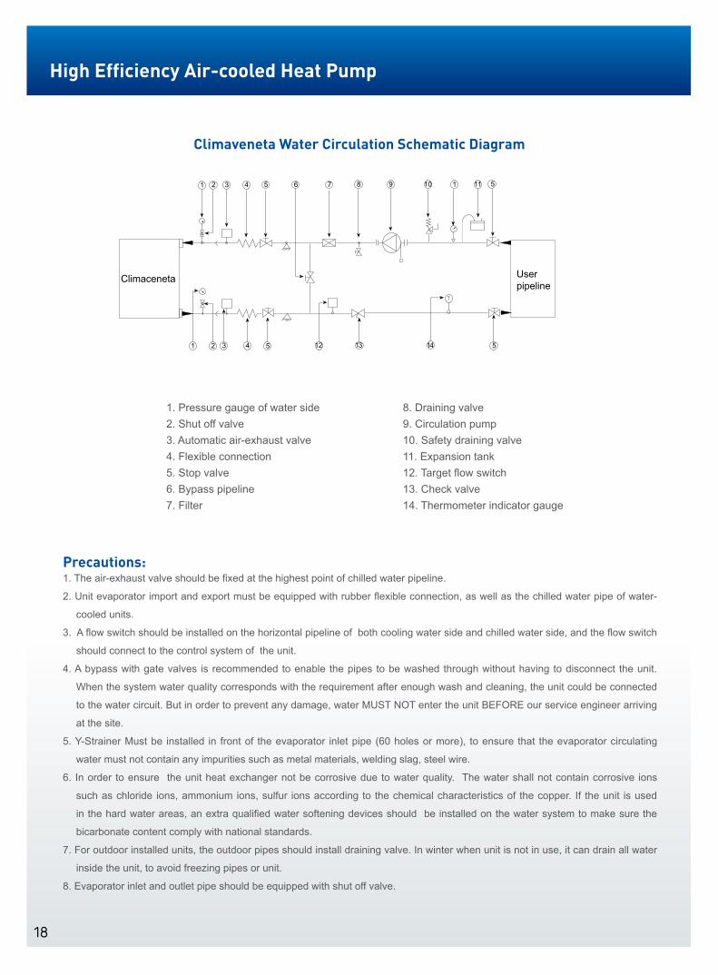
Climaveneta Water Circulation Schematic Diagram
1. Pressure gauge of water side2. Shut off valve3. Automatic air-exhaust valve4. Flexible connection5. Stop valve6. Bypass pipeline7. Filter
8. Draining valve9. Circulation pump10. Safety draining valve11. Expansion tank12. Target flow switch13. Check valve14. Thermometer indicator gauge
1 2 3 4 5 6 7 8 9 10 1 11 5
131 2 3 4 5 12 14 5
Climaceneta User pipeline
Precautions:1. The air-exhaust valve should be fixed at the highest point of chilled water pipeline.
2. Unit evaporator import and export must be equipped with rubber flexible connection, as well as the chilled water pipe of water-
cooled units.
3. A flow switch should be installed on the horizontal pipeline of both cooling water side and chilled water side, and the flow switch
should connect to the control system of the unit.
4. A bypass with gate valves is recommended to enable the pipes to be washed through without having to disconnect the unit.
When the system water quality corresponds with the requirement after enough wash and cleaning, the unit could be connected
to the water circuit. But in order to prevent any damage, water MUST NOT enter the unit BEFORE our service engineer arriving
at the site.
5. Y-Strainer Must be installed in front of the evaporator inlet pipe (60 holes or more), to ensure that the evaporator circulating
water must not contain any impurities such as metal materials, welding slag, steel wire.
6. In order to ensure the unit heat exchanger not be corrosive due to water quality. The water shall not contain corrosive ions
such as chloride ions, ammonium ions, sulfur ions according to the chemical characteristics of the copper. If the unit is used
in the hard water areas, an extra qualified water softening devices should be installed on the water system to make sure the
bicarbonate content comply with national standards.
7. For outdoor installed units, the outdoor pipes should install draining valve. In winter when unit is not in use, it can drain all water
inside the unit, to avoid freezing pipes or unit.
8. Evaporator inlet and outlet pipe should be equipped with shut off valve.
High Efficiency Air-cooled Heat Pump

19

Climaveneta Italy:36061 BASSANO DEL GRAPPA (VICENZA) ITALIA - VIA SARSON 57/cTEL. +39 / 0424 509 500 (r.a.) - TELEFAX +39 / 0424 509 509E-mail:[email protected] http://www.climaveneta.com
Climaveneta China:No,88 Baiyun Road Xinghuo Developing Zone ,Shanghai,China Post Code:201419TEL: +86-21-57505566 FAX: +86-21-57505797E-mail:[email protected] http://www.climaveneta.com.cn
Climaveneta Hongkong:Room 2003,CCT Telecom Building, 11 Wo Shing Street,Fotan,Shatin,N.T.,HongkongTEL: +852-26871755 FAX: +85-2-26873078E-mail:[email protected] http://www.climaveneta.asia
Climaveneta Vietnam:3rd Floor MEKONG Tower-235-241 Cong Hoa str Ward 13 Tan Binh Dist HCMCTEL: +848 6262 9966 FAX: +848 6262 9977E-mail: [email protected] http:// www.climaveneta.com
B125 CCU/01-04-2014EN-SHAll specification and data are subject to change without notice