ER-X INSTRUCTION MANUAL
4
INSTRUCTION MANUAL Area ionizer ER-X series CME-ERX No.0060-02V Thank you for purchasing Panasonic products. Read this Instruction Manual carefully and thoroughly for the correct and optimum use of this product. Kindly keep this manual in a convenient place for quick reference. WARNING ● Never use this product as device for personnel protection. ● In case of using devices for personnel protection, use products which meet laws or standards, such as OSHA, ANSI or IEC etc., for personnel protection applicable in each region or country. 1 FOR SAFETY USE WARNING ● This product produces high voltages. ● Do not use this product in places where there may be a danger of flammable or combustible items being present. ● To prevent electric shock and to conduct proper discharge, be sure to ground a frame ground (F.G.) terminal of a controller. ● Do not place hands near the discharge needle. Doing so may cause electric shock. ● Since the tip of the discharge needle is sharp, take sufficient care in handling the discharge needle, or injuries may result. ● The high-voltage cable between the head and the high-voltage unit must be fixed and the minimum bend radius is R30 mm or more. In case of using at the bend radius R30 mm or less and using at moving part may cause fire and break down, etc. of the high-voltage cable. ● Clean the discharge needle regularly (about once a week). Otherwise, optimum charge removal performance may not be achieved, and accidents or operating problems may occur. ● If this product is used in a confined space, ozone emitted from this product may be detrimental. Be sure to provide ventilation. ● Do not direct ionized air toward the face. Ozone may cause irritation to places such as the nose and throat. CAUTION ● This product has been developed / produced for industrial use only. ● Do not use this product for purposes other than electric charge removal. ● Do not use this product in environments which are outside the specification range, otherwise operating problems or damage may occur. In addition, the operating life of the product may become significantly reduced. ● This product is a precision device. Do not apply a shock to it by dropping, for example. Accidents or operating problems may occur. ● Never disassemble, repair or modify this product. Accidents or operating problems may occur. ● Do not throw this product in fire. It may explode or toxic fumes may be generated. ● Do not run the wires together with high-voltage lines or power lines or put them in the same raceway. This can cause malfunction due to induction. ● When connecting/removing the head or performing wiring or inspection work, be sure to turn off the power first. Not doing so may result in accidents, electric shock or operating problems. ● After connecting the cables, check that the connections are correct before turning on the power. If the cables are connected incorrectly, operating problems or accidents may occur. ● Verify that the supply voltage variation is within the rating. ● In case using switching regulator, be sure to connect F.G. terminal. ● When using as a CSA and UL compliant product, use a CLASS 2 CSA/UL certified power supply, or a CSA/UL certified power supply that has been evaluated as a Limited Power Source as specified in CAN/CSA-C22.2NO.60950-1/UL60950-1. ● Do not use a cable with any damage such as cracks or splitting. Risk of accidents and failure. ● Avoid use in a location with significant steam or dust, or in a location where the product may come in direct contact with water, oil, or welding spatter. ● Avoid use at an elevation higher than 2000m, and outdoor use. ● Do not touch the discharge needle with hard objects such as tools. If the discharge needle becomes broken, it will not provide sufficient charge removal performance, and moreover operating problems or accidents may occur. ● During installation, fasten the product securely. If it is not securely fastened or it is subjected to continuous vibration or shock, accidents or operating problems may result. ● Power cable that are 0.15mm 2 or more and 30m or less in total length for wiring. Also, keep the wiring as short as possible in order to prevent noise. ● When disposing of this product, treat it appropriately as industrial waste. ● After starting discharge, it takes approximately 30 minutes for charge removal performance to stabilize. Therefore, wait 30 minutes before adjusting ion balance. ● Use the correct combination of head, discharge needle unit and controller. 2 PART DESCRIPTION Bracket Discharge needle unit ER-XANT1 Head ER-X001 Head ER-X□ Discharge needle unit ER-XANT or ER-XANS Air inlet Head mounting bracket Discharge needle High-voltage cable (Note) High-voltage unit Head connection cable ER-XCCJ2H, ER-XCCJ5H or ER-XCCJ10H Controller ER-XC02 Power cable (optional) ER-XCC2 or ER-XCC5 High-voltage unit High-voltage cable (Note) Air inlet Note: The minimum bend radius of the high-voltage cable is R30 mm. <Controller> Discharge indicator (green) (Note) Lights up during discharge , blink- ing during discharge stopped. CHECK indicator (orange) Lights up when dirt, wear, etc. of the discharge needle is detected. Level meter indicator (green) Indicates static buildup around the head or the amount of ion generated from the head. Discharge control switch ON: Discharge allowed OFF: Discharge halt SET UP button Stores the settings for the amount of ion and the check threshold in memory. Discharge frequency setting switch Switches between discharge frequency settings. Ion balance setting switch Sets ion balance. Various setting switch Refer to “ 6 SETTING.” ERROR indicator (red) Lights up when abnormal discharge is detected. Note: An abbreviation of DISCHARGE. 3 INSTALLATION <Head installation> ● Using 2 M4 screws or 1 M6 screw, mount the head onto the equipment housing. In case using this prod- uct in where there is vibration, use spring washers etc. as a countermeasure. ● Loosen the angle adjustment screw, adjust the head angle, and then fasten the head with the tightening torque of 0.5 N∙m or less. ● The position of the head mounting bracket of the ER-X001 should be at least 20 mm from the end of the head. The tightening torque of the screw for head fixation should be 0.5 N•m or less. ● After mounting the head, set the controller according to the procedures in “ 6 SETTING” in order to appropriately remove static electricity. Angle adjustment screw M4 screw M6 screw Angle adjustment screw Screw for head fixation M4 screw Notes: 1) Be sure to ground the equipment housing onto which the head is mounted. 2) The distance between the head and the charge removing object should be 30 mm or more.If the static buildup of the charge removing object is 30 kV or more, set the distance to 50 mm or more. 3) If there is metal near the head or between the head and the charge removing object, ion is absorbed, hindering appropriate static removal. Install the head based on the above. 4) In case using the side mounting, the discharge frequency should be 10Hz or more. The discharge muzzle must exceed this line (surrounding metal.) Surrounding metal ● Back-side mounting (All frequencies) 50mm or more ● Side mounting (10Hz or more) 50mm or more ● Mouting ER-X001 Surrounding metal 20mm or more 20mm or more 5) When installing two or more heads in face to face or parallel using different frequency, keep the distance be- tween the heads 400mm or more. When installing the heads face to face, install heads in distance that the heads can parform the charge removal of a side of the object individualy. ● Face-to-face installation ● Parallel installation 100mm or more 100mm or more 50mm or more 50mm or more <High-voltage unit installation> ● Use 2 M4 screws or 2 M6 screws to fasten the head. The tightening torques for fastening, are as follows. When using M4 screws: 1.2N·m When using M6 screws: 2.5N·m M4 screw M6 screw Notes: 1) Do not place any objects on top of the high-voltage unit. 2) When using multiple heads, keep the distance of at least 10 mm between the high-voltage units. 3) When fastening the high-voltage unit using M6 screws, fasten before connecting the head connection cable. 4) Please fix the high-voltage unit of ER-X001 with M6 screw. 10mm or more <Controller installation> ● Mount the controller on a 35 mm wide DIN rail or using M4 screws. For mounting dimensions, refer to “ 16 DIMENSIONS” When mounting on a DIN rail When mounting using M4 screws 1 2 35 mm wide DIN rail Lock release lever M4 screw • Pull the lock release lever to remove this product from the DIN rail. • The tightening torque should be 1.2 N·m or less.
Transcript of ER-X INSTRUCTION MANUAL

INSTRUCTION MANUALArea ionizer ER-X series
CME-ERX No.0060-02V
Thank you for purchasing Panasonic products. Read this Instruction Manual carefully and thoroughly for the correct and optimum use of this product.Kindly keep this manual in a convenient place for quick reference.
WARNING ● Never use this product as device for personnel protection. ● In case of using devices for personnel protection, use products which meet laws or standards, such as OSHA, ANSI or IEC etc., for personnel protection applicable in each region or country.
1 FOR SAFETY USE
WARNING ● This product produces high voltages. ● Do not use this product in places where there may be a danger of flammable or combustible items being present.
● To prevent electric shock and to conduct proper discharge, be sure to ground a frame ground (F.G.) terminal of a controller.
● Do not place hands near the discharge needle. Doing so may cause electric shock. ● Since the tip of the discharge needle is sharp, take sufficient care in handling the discharge needle, or injuries may result.
● The high-voltage cable between the head and the high-voltage unit must be fixed and the minimum bend radius is R30 mm or more. In case of using at the bend radius R30 mm or less and using at moving part may cause fire and break down, etc. of the high-voltage cable.
● Clean the discharge needle regularly (about once a week). Otherwise, optimum charge removal performance may not be achieved, and accidents or operating problems may occur.
● If this product is used in a confined space, ozone emitted from this product may be detrimental. Be sure to provide ventilation.
● Do not direct ionized air toward the face. Ozone may cause irritation to places such as the nose and throat.
CAUTION ● This product has been developed / produced for industrial use only. ● Do not use this product for purposes other than electric charge removal. ● Do not use this product in environments which are outside the specification range, otherwise operating problems or damage may occur. In addition, the operating life of the product may become significantly reduced.
● This product is a precision device. Do not apply a shock to it by dropping, for example. Accidents or operating problems may occur.
● Never disassemble, repair or modify this product. Accidents or operating problems may occur. ● Do not throw this product in fire. It may explode or toxic fumes may be generated. ● Do not run the wires together with high-voltage lines or power lines or put them in the same raceway.This can cause malfunction due to induction.
● When connecting/removing the head or performing wiring or inspection work, be sure to turn off the power first. Not doing so may result in accidents, electric shock or operating problems.
● After connecting the cables, check that the connections are correct before turning on the power. If the cables are connected incorrectly, operating problems or accidents may occur.
● Verify that the supply voltage variation is within the rating. ● In case using switching regulator, be sure to connect F.G. terminal. ● When using as a CSA and UL compliant product, use a CLASS 2 CSA/UL certified power supply, or a CSA/UL certified power supply that has been evaluated as a Limited Power Source as specified in CAN/CSA-C22.2NO.60950-1/UL60950-1.
● Do not use a cable with any damage such as cracks or splitting. Risk of accidents and failure.
● Avoid use in a location with significant steam or dust, or in a location where the product may come in direct contact with water, oil, or welding spatter.
● Avoid use at an elevation higher than 2000m, and outdoor use. ● Do not touch the discharge needle with hard objects such as tools. If the discharge needle becomes broken, it will not provide sufficient charge removal performance, and moreover operating problems or accidents may occur.
● During installation, fasten the product securely. If it is not securely fastened or it is subjected to continuous vibration or shock, accidents or operating problems may result.
● Power cable that are 0.15mm2 or more and 30m or less in total length for wiring.Also, keep the wiring as short as possible in order to prevent noise.
● When disposing of this product, treat it appropriately as industrial waste. ● After starting discharge, it takes approximately 30 minutes for charge removal performance to stabilize. Therefore, wait 30 minutes before adjusting ion balance.
● Use the correct combination of head, discharge needle unit and controller.
2 PART DESCRIPTION
Bracket
Discharge needle unitER-XANT1
Head ER-X001
HeadER-X□
Discharge needle unitER-XANT or ER-XANSAir inlet
Headmounting bracket
Discharge needle
High-voltage cable (Note)
High-voltage unitHead connection cableER-XCCJ2H, ER-XCCJ5H or ER-XCCJ10H
ControllerER-XC02
Power cable (optional)ER-XCC2 or ER-XCC5
High-voltage unit High-voltage cable (Note)
Air inlet
Note: The minimum bend radius of the high-voltage cable is R30 mm.
<Controller>
Discharge indicator (green) (Note)
Lights up during discharge , blink-ing during discharge stopped.
CHECK indicator (orange)Lights up when dirt, wear, etc. of the discharge needle is detected.
Level meter indicator (green)Indicates static buildup around the head or the amount of ion generated from the head.
Discharge control switchON: Discharge allowedOFF: Discharge halt
SET UP buttonStores the settings for the amount of ion and the check threshold in memory.
Discharge frequency setting switchSwitches between discharge frequency settings.
Ion balance setting switchSets ion balance.
Various setting switchRefer to “ 6 SETTING.”
ERROR indicator (red)Lights up when abnormal discharge is detected.
Note: An abbreviation of DISCHARGE.
3 INSTALLATION<Head installation>
● Using 2 M4 screws or 1 M6 screw, mount the head onto the equipment housing. In case using this prod-uct in where there is vibration, use spring washers etc. as a countermeasure.
● Loosen the angle adjustment screw, adjust the head angle, and then fasten the head with the tightening torque of 0.5 N∙m or less.
● The position of the head mounting bracket of the ER-X001 should be at least 20 mm from the end of the head. The tightening torque of the screw for head fixation should be 0.5 N•m or less.
● After mounting the head, set the controller according to the procedures in “ 6 SETTING” in order to appropriately remove static electricity.
Angle adjustmentscrew
M4 screw
M6 screw
Angle adjustmentscrew
Screw for head fixation
M4 screw
Notes: 1) Be sure to ground the equipment housing onto which the head is mounted. 2) The distance between the head and the charge removing object should be 30 mm or more.If the static
buildup of the charge removing object is 30 kV or more, set the distance to 50 mm or more. 3) If there is metal near the head or between the head and the charge removing object, ion is absorbed,
hindering appropriate static removal. Install the head based on the above. 4) In case using the side mounting, the discharge frequency should be 10Hz or more.
The discharge muzzle must exceed this line(surrounding metal.)
Surroundingmetal
● Back-side mounting(All frequencies)
50mm or more
● Side mounting(10Hz or more)
50mm or more
● Mouting ER-X001
Surroundingmetal
20mm or more
20mmor more
5) When installing two or more heads in face to face or parallel using different frequency, keep the distance be-tween the heads 400mm or more. When installing the heads face to face, install heads in distance that the heads can parform the charge removal of a side of the object individualy.
● Face-to-face installation ● Parallel installation
100mm or more
100mm or more
50mm or more 50mm or more
<High-voltage unit installation> ● Use 2 M4 screws or 2 M6 screws to fasten the head.The tightening torques for fastening, are as follows.When using M4 screws: 1.2N·mWhen using M6 screws: 2.5N·m
M4 screw
M6 screw
Notes: 1) Do not place any objects on top of the high-voltage unit. 2) When using multiple heads, keep the distance of at least 10 mm
between the high-voltage units. 3) When fastening the high-voltage unit using M6 screws, fasten
before connecting the head connection cable. 4) Please fix the high-voltage unit of ER-X001 with M6 screw.
10mm or more
<Controller installation> ● Mount the controller on a 35 mm wide DIN rail or using M4 screws. For mounting dimensions, refer to “ 16 DIMENSIONS”
When mounting on a DIN rail When mounting using M4 screws
12
35 mm wide DIN rail
Lock release lever
M4 screw
• Pull the lock release lever to remove this product from the DIN rail.
• The tightening torque should be 1.2 N·m or less.

4 WIRING ● Power connector Pin arrangement
1 2 3 4 5
6 7 8 9 10
(Front view)
Housing: 5569-10A[Manufactured by Molex Inc.]
Terminal No. Terminal name Color code
1 0V Blue
2 COM(-) -
3 Discharge control input Pink
4 COM(OUT) Violet
5 F.G. terminal Green/Yellow
6 24V Brown
7 COM(+) -
8 COM(IN) White
9 Alarm output Orange
10 Error output BlackNote: Wire colors are colors of power supply cable of option.
● When connecting the output to negative common
24V DC±10%
※1 -
+
88
(Be sure to ground.)
(Brown)+V
COM(+)
(Violet) COM(OUT)
(Orange) Alarm output
(Black) Error output
(Pink) Discharge control input
(Blue)0V
COM(-)(Green/Yellow)F.G.
Mai
n ci
rcui
t Load
Load
(White) COM(IN)
● When connecting the output to positive common
8
24V DC±10%
※2
-
+
Mai
n ci
rcui
t
Load
Load
(Brown)+V
COM(+)
(Violet) COM(OUT)
(Orange) Alarm output
(Black) Error output
(Pink) Discharge control input
(Blue)0V
COM(-)(Green/Yellow)F.G. (Be sure to ground.)
(White) COM(IN)
*1 *2
Non-voltage contact orPNP transistor/open collector
or
Contact “closed” or transistor ON: Discharge haltContact “open” or transistor OFF: Starting discharge
Non-voltage contact orNPN transistor/open collector
or
Contact “closed” or transistor ON: Discharge haltContact “open” or transistor OFF: Starting discharge
Notes 1) In order to prevent electric shock and perform proper discharge , be sure to ground the F.G. terminal. In addition, the head of ER-X001 and the F.G. terminal of a controller are common. 2) To stop discharge, turn ON the discharge control input for 20 ms or longer. To start discharge, turn OFF (open)
the discharge control input. Discharge will start in 20 ms.
5 PIPING ● Air supplied to this product will reduce contamination of the discharge needle and improve the charge removal speed.
● The outer diameter of the air tube to fit to the air inlet portion of this product should be ø6 mm.
● Make sure that clean air (air containing no water, no oil and no dust) should be supplied.
● Since the pressure will drop when the air piping from the main pressure supply is extended or pneumatic components (e.g., needle valve, speed controller, mini filter) are added, keep an eye on the pressure supply to the ionizer making sure it is not in short supply. For the pneumatic components, select those that can accommodate the air supply flow rate.<Except ER-X001>Piping in the head
Air inlet
ø6 mm tube
Head section
(11.4mm)
<ER-X001>Piping in the High-voltage unit
φ6mm air tube
High-voltage unit
Air inlet
(11.6mm)
Note: After inserting the tube into the joint of this product, always make sure that the tube is all the way in and securely inserted.
Insufficient tube insertion will cause air leakage.
6 SETTING ● The amount of ion generation is set to enable appropriate charge removal. ● After mounting the head, follow the procedures below to configure the setting. ● When air is used, configure the setting while supplying air. ● Start the setting after 30 minuets of the discharge starting.
How to set the amount of ion generation1. Turn the discharge control switch ON and the discharge
control input “open” to start discharge.Make sure that the discharge indicator (green) lights up.
Discharge control switch
2. Depending on the installation distance, set the frequency using the discharge frequency setting switch.
● Guideline when air is not supplied
For head 1 For head 2
Discharge frequency setting switch
Discharge would be stopped at “Test A” and “Test E” of Head 2.
Installation distanceDischarge frequency setting switch
Frequency
30~50mm100 100Hz
70 70Hz
50~200mm50 50Hz
30 30Hz
200~500mm20 20Hz
10 10Hz
500~1,000mm5 5Hz
1 1Hz
● When air is supplied,Set the frequency higher than when air is not supplied. Try 50 Hz (factory default setting) first to see if it removes static electricity. Since using air, discharge distance from the object can be longer.
● If the amount of static build up on the charge removing object is large,Set the frequency lower or make the installation distance shorter.
● In case the voltage resistance of the object is low,Set the frequency higher or make the installation distance longer.
Note: Depending on the head, different frequencies are accepted. If it is set to a wrong frequency, the discharge stops and the discharge indicator blinks. For accepted frequencies, refer to "11 SPECIFICATIONS"
3. After mounting the head, adjust ion balance using the ion balance setting switch.
Turn to “-” to shift ion balance to the “-“ side. Turn to “+” to shift ion balance to the “+” side.
Ion balance setting switchFor head 1 For head 2
Note: Generally, ion reaching the charge removing object is affected by installation environment (nearby metals, temperature, humidity, etc.). Although this product has been adjusted for ion balance at the factory, the preadjusted ion balance may differ, depending on the customer’s installation environment. For more appropriate static removal, please adjust ion balance according to your installation environment.
4. Press the SET UP button to lock in the setting. After the setting is completed, level meter indicators change from blinking to lighting up.
SET UP button
Notes: 1) Conduct the maintenance before setting. 2) Before the setting up, be sure that the check indicator is turned OFF. In case the check the indicator lights up
or blinks, the set up is not started. For detail , reffere to “ 9 TROUBLE SHOOTING.”
3) This product works at factory setting before finishing setup (level meter indicator blinks.) And ion balance control function works at OFF in despite of setting of ion balance control switch. After press down the set up button and finishing he setting (level meter indicator lights up), starts ion balance control and Check detection(detecting function of ion generation depression )amount based on your enviroment.
4) It takes 30 seconds to 1 minute to complete a setup procedure. Do not change the ambient environment at the time. In case ambient environment is changed, the set up is not conducted and level meter indicator may blink.
5) In case the discharge frequency setting switch or the ion balance control switch is changed or installed envi-ronment is changed, conduct the setup again.
6) The set up is conducted to two heads. Do not wire head that you do not use. 7) Setting the ion balance setting switch shown right, level meter indicators blink. And pushing down the SET
UP button for 3 seconds in this setting, the setting will be the factory setting.
Initializing mode for head 1 Initializing mode for head 2
Various setting switchVarious setting switch Name Function
No.1Check level changeover switch
Switches between ion generation levels to output an alarm.ON: Lights up the CHECK indicator and outputs an alarm, when ion
generation is reduced to a level that affects static removal.OFF: Set this if you wish to be alerted soon after ion generation is
reduced.
No.2 Ion balancecontrol switch
Switches between automatic ion balance control function settings.ON: Enables automatic ion balance control function. Senses the amount of ion generation and automatically controls
it to match the setting of the ion balance setting switch.OFF: Disables automatic ion balance control function. Ion continues to generate at the discharge ratio setting of the
ion balance setting switch.
No.3Indicator changeover switch
Switches between indications of the level meter indicator (green).ON: Indicates the static buildup state of immediate
head. It shifts to the “+” or “-” side depending on the amount of buildup.
(Example) When the charge removing object is positively charged.
OFF: Indicates the amount of ion the head generates. Plus ion generated is indicated on the “+” side and minus ion on the “-” side.
(Example) When a sufficient amount of plus and minus ions are generated.
No.42 heads controlswitch
Sets ion generation timing for two heads. If the two heads have different discharge frequency, this setting will be invalid, and ion will be generated at the frequency timing of each head.ON: When head 1 is generating plus ion, head 2 also generates plus
ion.(synchronous mode)OFF: When head 1 is generating plus ion, head 2 generates minus ion.
(inversion mode)
No.5Error output changeover switch
Switches between Error output function.ON: Outputs an ERROR when ER-X has an error. (such as abnormal
discharging and disconnection of cables )OFF: Outputs an ERROR at the stop discharging. (in anomalous
condition or discharge control input )
No.6 ― Not used.
Notes: 1) All factory default settings are ON. 2) Checking function (detecting function of ion generation depression) is based on amount of ion generation
which was set in the set up.
7 Charging function ● By setting the discharge frequency setting switch for head 1 to "+ Charge" or "- Charge", head 1 can beused as charger.
● In the + charging mode, the upper 3 lamps of the level meter indi-cator light, while in the - charging mode, the lower 3 lamps light.
Notes: 1) Immediately after changing the discharging frequency setting switch, discharging stops and the level meter indicator lamps go out. To enable the charging function, turn charging OFF and then ON again.
2) Head 2 performs normal removal of static electricity. 3) The charging function cannot be used in the ER-X001. (The discharging stops.)
8 OUTPUT FUNCTIONS<Alarm output>
● Normally OFF ● The alarm output switches from OFF to ON at the occurrence of a reduction in ion generation, installation error, excessive discharge to nearby metals and abnormal setup data, etc.
● During an alarm, discharge (charge removal) continues. <Error output>
● Normally ON (Turning ON after 3 seconds of power suppling) ● The error output switches from ON to OFF at the occurrence of abnormal discharge, output short circuit, etc.
● During an error, discharge (charge removal) stops. ● The error will not be cleared until its cause is eliminated and the power or discharge control switch is turned on again.
● In addition to above, when setting error output changeover switch-off "DSC", the error output switches from ON to OFF at the stop discharging with discharge control switch or discharge control input.
Note: Refer to “ 9 TROUBLE SHOOTING” for actions to be taken at the occurrence of an alarm and error.
<Forced output functions> ● With this product, alarm output and error output can be forcedly-outputed by setting the discharge frequency setting switch for head 2 to "Test A"or "Test E", respectively.Discharge frequency setting switchfor head 2
Output Description
Alarm outputSet the discharge frequency setting switch for head 2 to "Test A". CHECK indicator turns up, and alarm output will be forced to switch from OFF to ON, generating an output.
Error outputSet the discharge frequency setting switch for head 2 to "Test E". ERROR indicator turns up, and error output will be forced to switch from ON to OFF, generating an output.
Note: During the enforced output, discharging of head 2 will be stopped.
9 TROUBLE SHOOTING ● Always be sure to turn off the power before checking the discharge part.Output Indicator Cause Remedy
-
Discharge indicator(Green) flashes
Discharge stopped.
Check whether the discharge control switch is ON, the discharge control input is not shorted or discharge frequency setting switch is not at "Test A" or "Test E". In the case of ER-X008, check that the discharge frequency setting switch is neither at 70 Hz nor 100 Hz. In the case of ER-X001, check that the discharge frequency setting switch is at either 20 Hz or 50 Hz.
Alarm ON
CHECK indicator (orange) lights up
The discharge needle unit is not in place.
Check whether all the discharge needle unit is properly fitted to the main body.
Discharge needle is dirty Clean the discharge needle and its surroundings. Refer to “ 10 MAINTENANCE” for details.
Discharge needle is worn
If the CHECK indicator (orange) does not turn off even after cleaning, replace the discharge needle unit, as it may be worn.
F.G. is not connected Check whether the F.G. terminal is connected.CHECK indicator (orange) flashes
Excessive discharge to nearby metals
Referring to “ 3 INSTALLATION” place the head away from nearby metals. Higher discharge frequency may help reduce excessive discharge.
ERROR indicator (red) flashes
Communication error between head and controller
Turn on the power again. If this error occurs as a result of power shutoff during setup, press the SET UP button again to complete setup.
Error OFF
ERROR indicator (red) lights up
Abnormal discharge to nearby metals.
Check whether the head is instal led in appropriate environment. Also, check whether any metal may come close to the discharge needle.
Abnormal discharge from the charge removing object.
A large amount of static buildup on the charge removing object may cause abnormal discharge. Increase the installation distance and the speed of charge removal with air.
Foreign objects attached to the discharge needle.
Foreign objects may cause abnormal discharge. Clean the discharge needle and its surroundings before use.
Dew condensation around the discharge needle.
If the temperature environment changes rapidly, abnormal discharge may result due to dew condensation. Clean the discharge needle and its surroundings, and use it under a stable environment.
Air is dirty.Water or oil content in the air attached to the discharge needle may cause abnormal discharge. When air is used, use clean dry air only.
Incorrect head onnection Use the correct combination of head and controller.Head not connected. Check whether the head is connected to the controller.
Damage If the error does not clear after turning on the power again and taking the above actions, contact us.
- Level meters (green) flash Setup is not completed. Press the SET UP button to lock in the setting.
-Level meters (green) light up in order
Performing setup It takes 30 seconds to 1 minute to complete the setup.
-Level meters (green) flashes
Initializing modeCheck that the position of the ion balance setting switch is in Initializing setting mode. Refer to “ 6 SETTING” for details.
-All indicator flash momentarily
Output short circuit. Check whether the output is shorted or whether the output load is too high.
● In case you got electric shock except discharge needle, F.G. terminal of controller is not connected properly. Be sure that the F.G. terminal is connected properly at the end.
10 MAINTENANCE ● Be sure to turn off the power and air before performing maintenance work. ● Since the tip of the discharge needle is pointed, take sufficient care when cleaning. ● Take care not to damage the tip of the discharge needle. ● Clean the discharge needle and its surroundings, where dirt or dust accumulates after long use.
● Clean it regularly, about once a week. Otherwise optimum charge removal performance may not be achieved, and accidents or operating problems may occur.
● The discharge needle is a consumable part. If charge removal performance does not return to normal after the discharge needle has been cleaned, then the needle unit should be replaced.
● When replacing the discharge needle unit because of natural wear and use, replace all units at the same time.
How to clean the discharge part1. Always make sure that the discharge control switch or the power is OFF. 2. Remove any dirt from the discharge needle and its surroundings using a brush,
cotton swab, etc. moistened with alcohol. <Except ER-X001>
Brush
Air outlet
Surrounding areaDischarge needle
<ER-X001>Air outlet
Surrounding area
Discharge needle
Swab
● In case of supplying air, there is possibility that around discharge needle or entire discharge unit get dirty by oil or moisture included in the supplying air. Before replacing the discharge unit, check the blot around discharge needle and clean the entire unit and check the dischargebility is recovered. (the discharge needle unit can be cleaned up easily with commercial super sonic washer.)
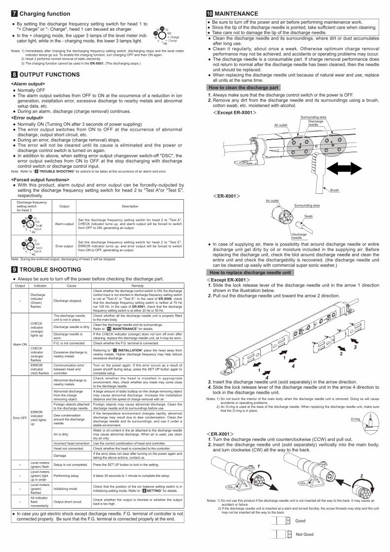
How to replace discharge needle unit <Except ER-X001>1. Slide the lock release lever of the discharge needle unit in the arrow 1 direction
shown in the illustration below. 2. Pull out the discharge needle unit toward the arrow 2 direction.
12
1
3
4
4
3. Insert the discharge needle unit (sold separately) in the arrow direction. 4. Slide the lock release lever of the discharge needle unit in the arrow 4 direction to
lock in the discharge needle unit. Notes: 1) Do not touch the interior of the main body when the discharge needle unit is removed. Doing so will cause
accidents or operating problems. 2) An O-ring is used at the base of the discharge needle. When replacing the discharge needle unit, make sure
that the O-ring is in place.
O-ring
<ER-X001>1. Turn the discharge needle unit counterclockwise (CCW) and pull out.2. Insert the discharge needle unit (sold separately) vertically into the main body,
and turn clockwise (CW) all the way to the back.
1
2
Notes: 1) Do not use this product if the discharge needle unit is not inserted all the way to the back. It may cause anaccident or failure.
2) If the discharge needle unit is inserted at a slant and turned forcibly, the screw threads may strip and the unit may not be inserted all the way to the back.
Good
Not Good

16 DIMENSIONS (Unit: mm)<Head part> ※ Please refer to the instruction manual of the head part for the form dimensions of ER-X001.
● Head
40
CD(E)
40 A28.5
9.4
22
18
30
28.5 B9.4
Model No. ER-X008 ER-X016 ER-X032 ER-X048 ER-X064A 40 120 280 440 600B 106 194 354 514 674C 138 226 386 546 706D 150 238 398 558 718(E) 163 251 411 571 731
4.2
9.4
6.2
18
2-6.5
● High-voltage unit
9.531
180
160
617
28
185
38
(18)
35
(25
)
17010.5
162
192
28.4
ø12
2-4.5 Mounting holes
2-6.5 Mounting holes High-voltage cable ø6.9
<Controller>
(23.2)
9.2
Head connectionconnectorS12B-PUDSS-1 [Manufactured by JST Mfg. Co., Ltd.]
For head 1For head 2
2-5.0 Mounting holes
(16) (16)
18
(9.
3 )44
5.2
767
39
797
6.5
53
10
604
(16
.5)
35 mm wide DIN rail
7
(14
0 ) 90
(103.5)
35.4
27.3
(9.1)
(14 )
(14 )
(9.1)
(8.
8 )
(8.
8 )
ø6
<Head connection cable> <Power cable>
(14
.4)
(22
.2)
(19.6)
(ø5
.3)
11 SPECIFICATIONSType HeadModel No. ER-X001 ER-X008 ER-X016 ER-X032 ER-X048 ER-X064Effective charge removal width 50mm 80mm 160mm 320mm 480mm 640mm
Charge removal time
0.3 second or less (Note 1)0.5 second or less (Note 2)
1 second or less (Note 3)
Ion balance ±30V or less (Note 2) (Note 3) (Note 4)
Discharge method Pulse AC method (Note 5)Discharge output voltage Approx. 7,000VOzone generation 0.01ppm or less (Note 2) (Note 3)Maximum air pressure 0.5MPaApplicable fluid Air (dried clean air) (Note 6)
Ambient temperature 0 to +50°C (ER-X001:0 to +40°C) (with no dew condensation)(Note7), For storage: -10 to +65°C
Ambient humidity 35 to 65%RH. For storage: 35 to 85%RH
Vibration resistance 10 to 55Hz frequency (ER-X001:10 to 150Hz frequency), 0.75mm amplitude for 2 hours in each of XYZ directions (when the power is off)
Shock resistance Resistance 100 m/s2 (approx. 10G), 3 times in each of XYZ directions (when the power is off)Enclosure grounding method Floating
MaterialMain unit enclosure: PPS, Stainless steal (SUS).Head mounting bracket: Stainless steal (SUS).
Discharge needle: PFA, PC, PPS, Tungsten (Note 8). High-voltage cable length 1.2m 0.5m 0.5m (Note 9)
Weight Approx. 370g
Approx. 330g
Approx. 410g
Approx. 530g
Approx. 650g
Approx. 780g
Notes: 1) In condition of discharge distance 50mm, center of the product, discharge wavelength 50Hz and air supply 60ℓ/min(0.3MPa). 2) In condition of discharge distance 50mm, center of the product, discharge wavelength 50Hz and no air supply. 3) In condition of discharge distance 100mm, center of the product, discharge wavelength 50Hz and no air supply. 4) Ion balance is average of plus and minus. Also, the specification value is typical value in condition of less
than ±10°C ambient temperature change, set the ion balance after 30 minutes of the discharge starting, switching on the ion balance control function.
5) For ER-X001 the discharge frequencies of 50Hz, 20Hz are accepted. For ER-X008 and high-voltage cables 1m/2m, the discharge frequencies of 50Hz, 30Hz, 20Hz, 10Hz, 5Hz, and 1Hz are accepted. For other heads, 100Hz, 70Hz, 50Hz, 30Hz, 20Hz, 10Hz, 5Hz, and 1Hz are accepted.
6) The dried clean air is dried (dew point: equivalent of -20°C) and filtered (mesh-size: equivalent of 0.01μm) air. 7) The High and Low Temperature Resistant type of head (-60 to +200℃ ) are also available. Please contact us
for details. 8) Silicon needles type of head are also available. Please contact us for details. 9) High-voltage cables are also available in 1m and 2m lengths. Please contact us for details.
Type ControllerModel No. ER-XC02Number of charge removal heads connected Maximum 2 units
Supply voltage 24V DC±10%
Current consumption 450mA or less when connecting 1 heads.800mA or less when connecting 2 heads.
Indictor Displays status of Head 1 and 2DSC (Discharge) Green LED [Lights up during discharge , blinking during discharge stopped.]CHECK Orange LED [Lights up when dirt, wear, etc. of the discharge needle is detected.]ERROR Red LED [Lights up when abnormal discharge is detected.]Level meter Green LED [5 levels, Lights up depending on amount of the charge or ion generation.]
OutputALARM, ERRORCOM (COM OUT)
PhotoMOS relay output• Maximum load current: 100mA• Applied voltage: 30VDC or less (between output-output common) • Residual voltage: 1.5V or less (at load current of 100mA)
Output operationALARM: ON when dirt or wear of the discharge needle is detected; OFF when operation is normal. ERROR: OFF when abnormal discharge is detected; ON when operation is normal.
Short-circuit operation Equipped (automatic reset type)
IntputDischarge control input (DSC OFF) COM(COM IN)
Photo coupler input・Input current: 4.5mA or less・Input voltage: 30VDC or less (between input-input common)・Input impedance: about 7kΩ.
Input operation Discharge allowed: Open. Discharge halt: 24V or 0V shorted.Pollution level 2Ambient temperature 0 to +50°C (with no dew condensation). For storage: -10 to +65°CAmbient humidity 35 to 65%RH. For storage: 35 to 85%RHOperating altitude 2,000 m or less (Note 1)
Voltage resistance AC 1000V, 1 minute, completely charged part/between enclosuresAC 500V, 1 minute, charged part/between F.G.
Insulation resistance 20 MΩ or more at DC 250V, completely charged part/between enclosures
Vibration resistance 10 to 150 Hz frequency, 0.75mm amplitude for 2 hours in each of XYZ directions (when power is off)
Shock resistance Resistance 100 m/s2 (approx. 10G), 3 times in each of XYZ directions (when the power is off)Over-voltage category IEnclosure grounding method FloatingMaterial Enclosure: ABSWeight Approx. 130g
AccessoriesPower supply / I/O connector: 1 set(Housing 5557-10R, terminal 5556TL [manufactured by Molex Inc.])Ground wire approx. 3.7m: 1pc.
Notes: 1) Do not use or store the device in an environment where the air pressure is higher than the atmospheric pressure at an altitude of 0 meters.
Type Head connection cableModel No. ER-XCCJ2H ER-XCCJ5H ER-XCCJ10HLength 2m 5m 10mCable Cabtyre cable with connectors at both endsWeight Approx. 120g Approx. 290g Approx. 560g
12 OPTIONS (sold separately)Model No. ER-X001 ER-X008 ER-X016 ER-X032 ER-X048 ER-X064Spare discharge needle unit ER-XANT1 ER-XANT2 ER-XANTDischarge part protective cover - - ER-XACVR
AC adapter ER-XAPS-EXPower cables ER-XCC2 (2m),ER-XCC5 (5m)
13 CE MARKED PRODUCT ● This product is CE marked product.
14 CSA/UL compliant product ● This product complies with CSA and UL standards, and has been certified by TUV SUD.
15 RoHS DirectiveThis product is in compliance with the RoHS Directive (EU).
http://panasonic.net/id/pidsx/globalOverseas Sales Division (Head Office) 2431-1 Ushiyama-cho, Kasugai-shi, Aichi, 486-0901, Japan Phone: +81-568-33-7861 FAX: +81-568-33-8591For sales network, please visit our website.
PRINTED IN JAPAN © Panasonic Industrial Devices SUNX Co., Ltd. 2017