ER DR Dimming Rack - WPIusers.wpi.edu/~theatre/res/resources/Manuals/Lighting/L_ErDimming... · ER...
42
ETC ARCHITECTURAL ER & DR Dimming Rack Unison ™ Lighting Control System Owner’s Manual
-
Upload
phamnguyet -
Category
Documents
-
view
213 -
download
0
Transcript of ER DR Dimming Rack - WPIusers.wpi.edu/~theatre/res/resources/Manuals/Lighting/L_ErDimming... · ER...

E T C A R C H I T E C T U R A L
ER & DR Dimming RackU n i s o n™ L i g h t i n g C o n t r o l S y s t e m
Owner’s Manual


Contents
IntroductionWarning and notice conventions ...................................................................................... 3Important notes ................................................................................................................. 3
System configuration To access configuration menus .............................................................................................. 5To initialize a dimming rack ..................................................................................................... 5To detail dimming circuits........................................................................................................ 6To enter Dimmer Doubling (DD) settings................................................................................. 7To set dimmer levels in the Test submenu.............................................................................. 8To set dimmer levels in the Set All submenu.......................................................................... 8To set the Backup look............................................................................................................. 9
Configuring the Architectural ProcessorTo load a Unison Light Manager configuration in to the control processor.......................... 11To bind control stations to the architectural processor ........................................................ 12To unbind control stations (optional) .................................................................................... 13To enter the Date and Time local control settings ............................................................... 14To enter your location settings .............................................................................................. 15Working in the Setup menu ................................................................................................... 16Working in the Diagnostics menu.......................................................................................... 19To save the installed configuration ...................................................................................... 20
Maintaining Your Unison System Cleaning dimming rack air filters.......................................................................................... 21
Appendix A: Frequently Asked Questions ............................................................................ 23Appendix B: Error Message Chart ......................................................................................... 27Appendix C: Wall Station ID Chart ......................................................................................... 29Appendix D: Rack Configuration Chart ................................................................................. 31Appendix E: Architectural Menu Flow Chart ....................................................................... 33Appendix F: Dimmer Menu Flow Chart ................................................................................. 35Appendix G: U.S. Time Zone and Location Map .................................................................. 37

2 Electronic Theatre Controls, Inc.

Introduction
Warning and notice conventionsThroughout this guide, these symbols are used to indicate warning, caution and points of interest.
Note
Calls your attention to important additional information.
Warning
Alerts you to dangers that could cause serious injury or death to you or those working with you.
Caution
Alerts you to dangers that could damage the equipment.
Important NotesWarning: Risk of electrical shock.
This equipment should be installed and wired by a qualified electrician. Always follow applicable building and electrical codes when installing this equipment. If you are not sure if your installation complies with local or national codes, contact your local building inspector. Service by qualified personnel only.
Unison ER and DR Dimming Rack Owner’s Manual 3

4 Electronic Theatre Controls, Inc.

Unison ER and DR Dimming Rack Owner’s Manual 5
System configurationUnison rack dimming software version 2.0
To access configuration menus1. Press the concealed menu activate button for three seconds. Menu screen will
appear. See Figure 1 for concealed button.
2. Press [up arrow] or [down arrow] to scroll through bracketed options.
3. Press [Enter] to move bracket placement to the right.
4. Press [Exit] to move bracket placement left.
To reset a Control ModuleWhen the rack door is open, a Reset button is available in the top right corner. Pressing it restarts the Control Module using saved settings. Resetting will temporarily interrupt all Control Module processing. Lights will flash momentarily or may go out while system boots.
To initialize a dimming rackInitialization refers to the programming of rack voltage, size and DMX start address. The first time you access menus on a Unison dimming rack, you must initialize the dimming system processor.
1. Complete Rack Configuration Chart (Appendix D) on page 31.
2. Press the concealed "Initialization activate" button for three seconds. The [Stat] menu will be displayed.
3. Use [▲] or [▼] to scroll to the [Rack] menu.
4. Press [Enter] to move the brackets underneath Control and use [▲] or [▼] to select the the appropriate dimming rack or external processing rack control module.
5. If you have selected a dimming rack, move the brackets underneath Rack and use [▲] or [▼] to select either DR6 or DR12.
6. Press [Enter] to move the brackets underneath Volt and use [▲] or [▼] to select the voltage that matches your feed, either 100-120, 120 Delta or 277 VAC.
7. Press [Enter] to move the brackets underneath Start and use [▲], or [▼] to enter a DMX512 starting address for your rack between 001 and 512.
DMX start address - the DMX512 channel number (between 1 and 512) applied to the first dimmer in the rack. Succeeding DMX channel numbers are automatically applied to the remaining dimmers.
Continued on next page...
LIGHTING CONTROL SYSTEM
UNISONENTER
EXIT
LCD Display Scroll up
Enter (Scroll right)
Exit (Scroll left)
Scroll down
MENU [Stat] System OK
Initialization activate
Figure 1: Control module interface for the Dimmer Menu
Reset button
Unison Menu activate
Menu Control Rack[Rack] Unknown ER4
Menu Volt Rack[ 100-120 ]
Menu Start Rack [ 001 ]

8. Press [Enter] to move the brackets underneath Sequencing. Select either Straight or Balanced.
Straight or Balanced refers to how the DMX addresses will be distributed to the dimmers. Straight indicates that the distribution will be sequential starting at one. Balanced indicates that sequential loads will be distributed evenly over the three phases in the rack.
Note: Single-phase racks cannot be phase balanced, as the racks are not split evenly.
9. Press [Enter] then [Exit]. The display changes to Update Rack? Use [▲] or [▼] to select Yes. Press [Enter] again to save changes and leave the Rack menu.
To detail dimming circuitsThe Unison dimming processor is designed to control (dim) multiple lighting circuits. Control of each circuit is based on installed module type, connected load type, DMX address and circuit mode.
1. Access configuration menu (press the Unison Menu activation button.)
2. Scroll to [Cnfg] with [▲] or [▼] and press [Enter]. The brackets move to the circuit number.
Note: Circuit numbers start with “1” for the first dimmer in the top slot of the rack. A rack can have one or two dimmer circuits per module. Dimmer load wire lugs are also labeled by circuit number.
3. Select the desired circuit number with [▲] or [▼] and press [Enter]. The display changes to Module Type.
4. Select the correct module type with [▲] or [▼] and press [Enter]. The display changes to Load Type.
Table 1: Dimmer modules and load types
Module Type Description Compatible loads100-120 Volt Rack
AFM Required in empty dimmer slots
None
D15 and D20
D15E and D20ED15G and D20G
Standard 15 or 20 amp dimmer
500µs rise time300µs rise time
Incandescent, 2- and 4-wire fluorescent, Low voltage, Neon,
Cold cathode (CC), Non-Dim
R15 and R20 15 and 20 amp mechanically held relay
Any switched load
D15F and D20F 15 and 20 amp fluorescent dimmer
3 wire fluorescent dimmer ballasts
CC 15 and CC 20 Direct connection from line lug to load lugs protected by a 15 or 20 amp circuit breaker
Non-dim loads like color changer power supplies
277 Volt Rack
AR15 and AR20 15 and 20 amp mechanically held relay
Any switched load
AD15 and AD20 15 and 20 amp dimmer200µs rise time
Incandescent, 2- and 4-wire fluorescent, Low voltage, Neon,
Cold cathode (CC), Non-DimAD15F and AD20F 15 and 20 amp fluorescent
dimmer3 wire fluorescent dimmer
ballasts
Menu SequencingRack [ Straight ]
Update Rack? [Yes]
Menu Ckt [Cnfg] 001
Menu CircuitCnfg [001]
Ckt Module 001 [ D15/D20 ]
Note: "CC" (constant current) module types do not indicate Cold Cathode.
6 Electronic Theatre Controls, Inc.
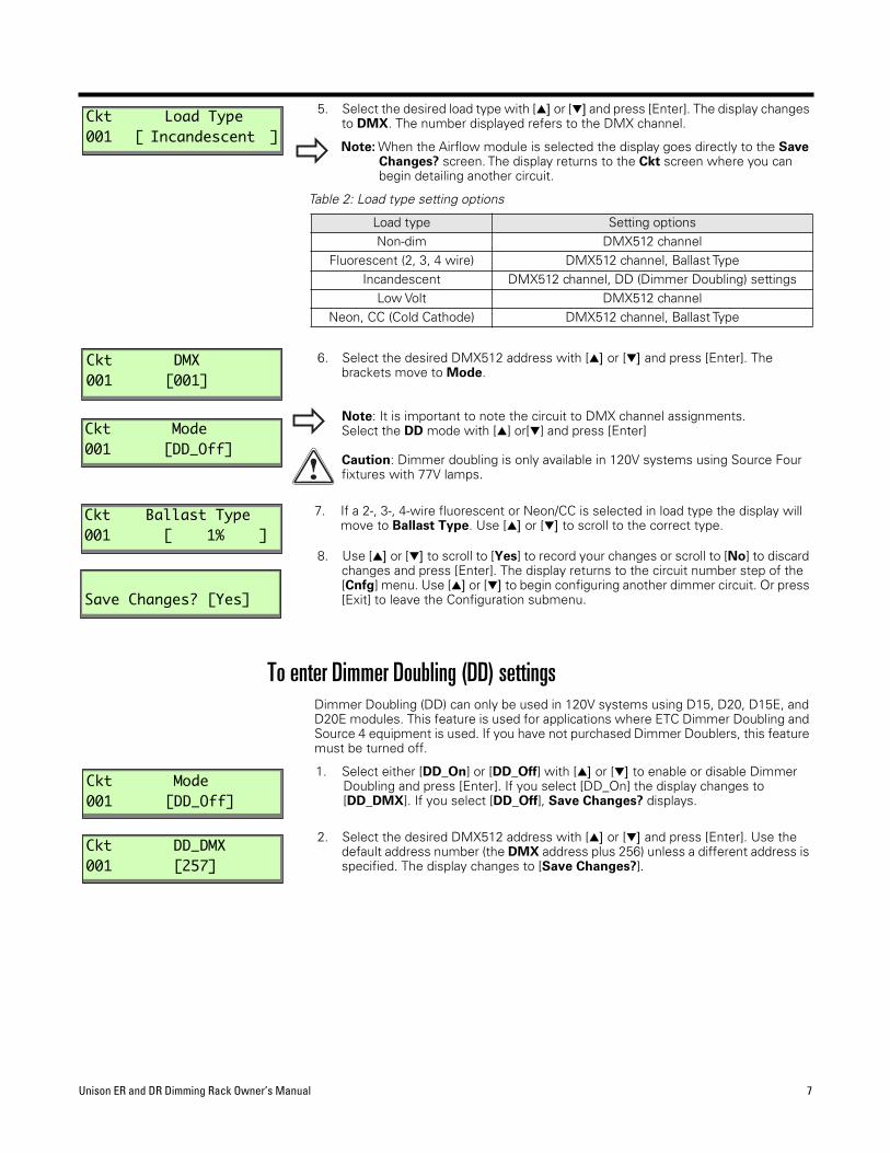
5. Select the desired load type with [▲] or [▼] and press [Enter]. The display changes to DMX. The number displayed refers to the DMX channel.
Note: When the Airflow module is selected the display goes directly to the Save Changes? screen. The display returns to the Ckt screen where you can begin detailing another circuit.
Table 2: Load type setting options
6. Select the desired DMX512 address with [▲] or [▼] and press [Enter]. The brackets move to Mode.
Note: It is important to note the circuit to DMX channel assignments.Select the DD mode with [▲] or[▼] and press [Enter]
Caution: Dimmer doubling is only available in 120V systems using Source Four fixtures with 77V lamps.
7. If a 2-, 3-, 4-wire fluorescent or Neon/CC is selected in load type the display will move to Ballast Type. Use [▲] or [▼] to scroll to the correct type.
8. Use [▲] or [▼] to scroll to [Yes] to record your changes or scroll to [No] to discard changes and press [Enter]. The display returns to the circuit number step of the [Cnfg] menu. Use [▲] or [▼] to begin configuring another dimmer circuit. Or press [Exit] to leave the Configuration submenu.
To enter Dimmer Doubling (DD) settingsDimmer Doubling (DD) can only be used in 120V systems using D15, D20, D15E, and D20E modules. This feature is used for applications where ETC Dimmer Doubling and Source 4 equipment is used. If you have not purchased Dimmer Doublers, this feature must be turned off.
1. Select either [DD_On] or [DD_Off] with [▲] or [▼] to enable or disable Dimmer Doubling and press [Enter]. If you select [DD_On] the display changes to [DD_DMX]. If you select [DD_Off], Save Changes? displays.
2. Select the desired DMX512 address with [▲] or [▼] and press [Enter]. Use the default address number (the DMX address plus 256) unless a different address is specified. The display changes to [Save Changes?].
Load type Setting optionsNon-dim DMX512 channel
Fluorescent (2, 3, 4 wire) DMX512 channel, Ballast Type Incandescent DMX512 channel, DD (Dimmer Doubling) settings
Low Volt DMX512 channelNeon, CC (Cold Cathode) DMX512 channel, Ballast Type
Ckt Load Type001 [ Incandescent ]
Ckt DMX 001 [001]
Ckt Mode001 [DD_Off]
Ckt Ballast Type001 [ 1% ]
Save Changes? [Yes]
Ckt Mode001 [DD_Off]
Ckt DD_DMX 001 [257]
Unison ER and DR Dimming Rack Owner’s Manual 7

To set dimmer levels in the Test submenuYou can use the Test submenu to set dimmer levels to test your dimmer circuit wiring or lighting load operation. Test also allows you to view DMX levels being received by the dimming processor.
1. Access the configuration menu (press the Unison Menu activation button.)
2. Scroll to [Test] with [▲] or [▼] and press [Enter]. The brackets move to Ckt. The DMX input value for that circuit is displayed between a range of 0 and 255.
3. Use [▲] or [▼] to scroll to the desired circuit number and press [Enter]. The brackets move to Level. This shuts off all DMX to the rack. DMX levels are held at last look and DMX level changes have no effect.
4. Use [▲] or [▼] to scroll to the circuit output level. Circuit output will continuously match the levels as they scroll. Press [Exit] to set levels on another circuit or [Enter] to go to Restore DMX?. (Restoring DMX will cancel all test levels.)
Note: Circuit levels will remain at their test setting when you press [Exit]. You can set levels for all the dimmer circuits by repeating steps 2 and 3.
5. Use [▲] or [▼] to scroll to [Yes] to clear the test settings and restore DMX or [No] to temporarily keep the look and press [Enter].
Note: If you keep the test settings, DMX512 input is disabled until you return to the Test menu and restore DMX.
To set dimmer levels in the Set All submenuThe [Set All] submenu is an additional test menu. It allows you to change all of the levels in the dimmer rack.
1. Access the configuration menu (press the Unison Menu activation button.
2. Scroll to [Set All] with [▲] or [▼] and press [Enter].
3. Use [▲] or [▼] to change the level of all dimmers.
4. Press [Enter], and use [▲] or [▼] to scroll to [Yes] to clear the [Set All] and restore DMX. Or [No] to temporarily keep the look and press [Enter].
Menu Ckt Level[Test] 001 000
Menu Ckt LevelTest [001] 000
Menu Ckt LevelTest 001 [000]
Restore DMX? [Yes]
Menu Level[Set All] ---
8 Electronic Theatre Controls, Inc.

To set the Backup lookIn the event of console failure, the backup look enables you to activate a single preset at the CMd or CMEd.
1. Access the configuration menu.
2. Scroll to [Backup] with [▲] or [▼] and press [Enter]. The brackets move to Mode.
3. Scroll to [Record] with [▲] or [▼] and press [Enter]. The system will record current levels.
Note: Any "Test" or "Set All" levels will also be recorded if DMX is not active.
4. Use [▲] or [▼] to select if programmed backup look should play at boot-up of system processor. Select [Yes] or [No] and press [Enter].
5. Scroll to [Yes] to save changes and press [Enter].
Note: playing the backup look will disable DMX or test levels to the dimming rack.
Menu Mode[Backup] None
Menu ModeBackup [Record]
Menu Play At BootBackup [No]
Save Changes? [Yes]
Unison ER and DR Dimming Rack Owner’s Manual 9

10 Electronic Theatre Controls, Inc.
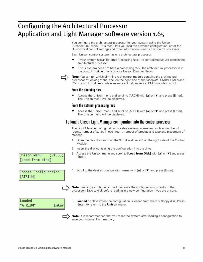
Configuring the Architectural ProcessorApplication and Light Manager software version 1.65
You configure the architectural processor for your system using the Unison (Architectural) menu. This menu lets you load the provided configuration, enter the Unison local control settings and other information used by the control processor.
Each Unison control system has one architectural processor.
▼ If your system has an External Processing Rack, its control module will contain the architectural processor.
▼ If your system does not have a processing rack, the architectural processor is in the control module of one of your Unison Dimmer Racks.
Note: You can tell which dimming rack control module contains the architectural processor by looking at the label on the right side of the faceplate. CMBd, CMEd and CMEi control modules contain an architectural processor. CMd modules do not.
From the dimming rack▼ Access the Unison menu and scroll to [ARCH] with [▲] or [▼] and press [Enter].
The Unison menu will be displayed.
From the external processing rack▼ Access the Unison menu and scroll to [ARCH] with [▲] or [▼] and press [Enter].
The Unison menu will be displayed.
To load a Unison Light Manager configuration into the control processorThe Light Manager configuration provides system parameters such as number of rooms, number of zones in each room, number of presets and type and placement of stations.
1. Open the rack door and find the 3.5" disk drive slot on the right side of the Control Module.
2. Insert the disk containing the configuration into the drive.
3. Access the Unison menu and scroll to [Load from Disk] with [▲] or [▼] and press [Enter].
4. Scroll to the desired configuration name with [▲] or [▼] and press [Enter].
Note: Reading a configuration will overwrite the configuration currently in the processor. Save to disk before reading in a new configuration if you are unsure.
5. Loaded displays when the configuration is loaded from the 3.5" floppy disk. Press [Enter] to return to the Unison menu.
Note: It is recommended that you reset the system after loading a configuration to save your internal flash memory.
Unison Menu (v1.65)[Load from disk]
Choose Configuration[ATRIUM]
Loaded "ATRIUM" Enter
Unison ER and DR Dimming Rack Owner’s Manual 11

To bind control stations to the architectural processorBefore the architectural processor can identify signals from the wall stations, it has to link each control station to its ID number. This process is called "binding". Systems with a single station of a particular type (preset, fader, LCD) will automatically bind with the associated ID number.
1. Access the Unison Menu, scroll to [Setup] with [▲] or [▼] and press [Enter].
Note: Refer to the Control Station ID Chart to find the station ID number of the control you wish to bind.
2. From the Setup display scroll to [Stations] with [▲] or [▼] and press [Enter].
3. From the Stations display, scroll to [Connect] with [▲] or [▼] and press [Enter].
4. The Choose Room display shows a list of rooms with unbound control stations. Scroll to the desired room with [▲] or [▼] and press [Enter].
5. The Choose Section display shows the sections available in divided rooms. Scroll to the desired section with [▲] or [▼] and press [Enter].
Note: If the selected room is not divided, this display is skipped.
6. The Choose Station display scrolls the names of unbound control stations in the section. Scroll to the desired control station with [▲] or [▼] and press [Enter].
7. When a control station name is selected, the Connect to display shows a list of the station IDs available on the network for that type of station. Scroll to the correct ID with [▲] or [▼] and press [Enter].
Note: When you are in the Connect menu, pressing a control button on the station you choose in Step 6 will display the ID number of that station. You can use this feature to bind stations if you lose your Control Station ID Chart.
8. The LCD will display [Connected] when the station is bound. The control station is now ready. Press [Enter] to show the next room or section with unbound control stations. Press [Exit] to leave the Connect menu.
Note: After binding stations, ETC recommends saving the configuration.
Unison Menu (v1.65)[Setup]
Setup [Stations]
Stations [Connect]
Choose Room [Dining]
Choose Section [Banquet]
Choose Station [Fader 1]
Connect to: [OOOO Ð 6O32 Ð 6783]
"Fader 1" Connected Enter
12 Electronic Theatre Controls, Inc.
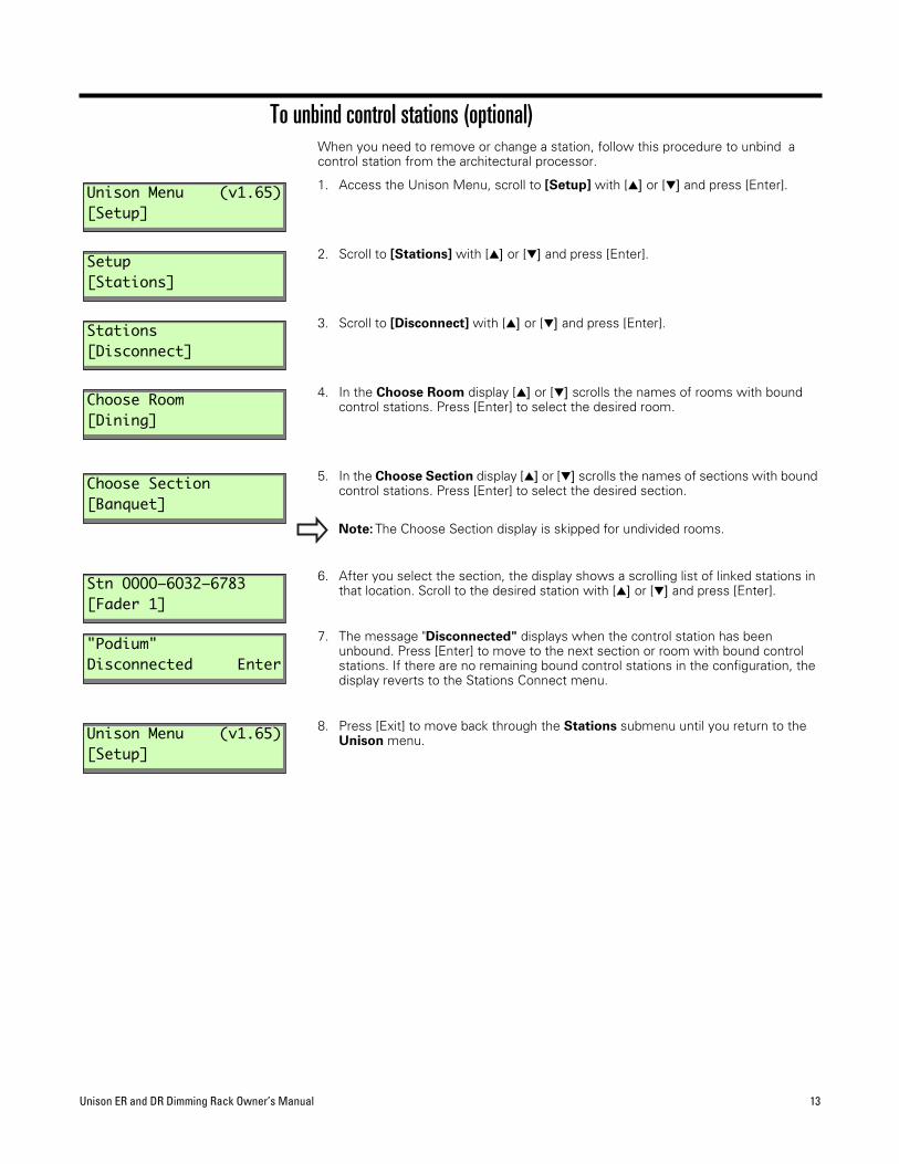
To unbind control stations (optional)When you need to remove or change a station, follow this procedure to unbind a control station from the architectural processor.
1. Access the Unison Menu, scroll to [Setup] with [▲] or [▼] and press [Enter].
2. Scroll to [Stations] with [▲] or [▼] and press [Enter].
3. Scroll to [Disconnect] with [▲] or [▼] and press [Enter].
4. In the Choose Room display [▲] or [▼] scrolls the names of rooms with bound control stations. Press [Enter] to select the desired room.
5. In the Choose Section display [▲] or [▼] scrolls the names of sections with bound control stations. Press [Enter] to select the desired section.
Note: The Choose Section display is skipped for undivided rooms.
6. After you select the section, the display shows a scrolling list of linked stations in that location. Scroll to the desired station with [▲] or [▼] and press [Enter].
7. The message "Disconnected" displays when the control station has been unbound. Press [Enter] to move to the next section or room with bound control stations. If there are no remaining bound control stations in the configuration, the display reverts to the Stations Connect menu.
8. Press [Exit] to move back through the Stations submenu until you return to the Unison menu.
Unison Menu (v1.65)[Setup]
Setup [Stations]
Stations [Disconnect]
Choose Room[Dining]
Choose Section[Banquet]
Stn OOOOÐ6O32Ð6783[Fader 1]
"Podium" Disconnected Enter
Unison Menu (v1.65)[Setup]
Unison ER and DR Dimming Rack Owner’s Manual 13

To enter the Date and Time local control settingsFollow this procedure to set the date and time in the astronomical time clock in the architectural processor.
1. Access the Unison Menu, scroll to [Setup] with [▲] or [▼] and press [Enter].
2. Scroll to [Date/Time] with [▲] or [▼] and press [Enter].
3. The Year display scrolls dates from [1995] to [2099] with [▲] or [▼]. Press [Enter] to select the correct year.
4. The Month display scrolls all 12 months with [▲] or [▼]. Press [Enter] to select the correct month.
5. The Date display scrolls days from 1 to 31 with [▲] or [▼]. Press [Enter] to select the correct date.
6. The Hour display scrolls 24 hours in a 12 hour AM/PM format with [▲] or [▼]. Press [Enter] to select the correct hour.
7. The Minute display scrolls from 00 to 59 minutes with [▲] or [▼]. Press [Enter] to select the correct minute.
8. Date/Time Set appears when the Date/Time menu is complete. Press [Enter] to return the display to the Unison menu.
Unison Menu (v1.65)[Setup]
Setup [Date/Time]
Year [2000]
Month [October]
Date [9]
Hour [11 AM]
Minute [11]
Date/Time Set Enter
14 Electronic Theatre Controls, Inc.

To enter your location settingsThe Location menu allows you to enter the installation latitude, longitude, elevation, and time zone into the Unison astronomical time clock. Refer to the Location Map on page 37.
1. Access the Unison Menu, scroll to [Setup] with [▲] or [▼] and press [Enter].
2. Scroll to [Location] with [▲] or [▼] and press [Enter].
3. The Longitude (deg) display scrolls from 0 to 179 degrees East and West with [▲] or [▼]. Press [Enter] to select the correct value.
4. The Longitude (min) display scrolls from 0 to 59 minutes of longitude with[▲] or [▼]. Press [Enter] to select the correct value.
5. The Latitude (deg) display scrolls from 0 to 89 degrees North and South with [▲] or [▼]. Press [Enter] to select the correct value.
6. The Latitude (min) display scrolls from 0 to 59 minutes of latitude with [▲] or [▼]. Press [Enter] to select the correct value.
7. The Altitude display scrolls elevation values in increments of 100 feet (28.5m) with [▲] or [▼]. Press [Enter] to select the correct value.
8. The Time Zone display scrolls from 1 to 12 hours before (+) or after (–) Greenwich Mean Time. Scroll to the correct Time Zone with [▲] or [▼] and press [Enter].
9. The Daylight Savings display scrolls from [Observed] to [Not Observed] with [▲] or [▼]. Press [Enter] to select the desired daylight savings setting.
10. Location Set displays when the Set Location menu is complete. Press [Enter] to return to the Unison menu.
Unison Menu (v1.65)[Setup]
Setup [Location]
Longitude (deg)[89 West]
Longitude (min)[30]
Latitude (deg)[43 North]
Latitude (min)[15]
Altitude (feet)[900]
Time Zone (hours)[-6]
Daylight Savings[Observed]
LocationSet Enter
Unison ER and DR Dimming Rack Owner’s Manual 15

Working in the Setup menuAll of the following Setup menu options will allow you to access, change or set information about your Unison system. See "Appendix E: Architectural Menu Flow Chart" on page 33, for help on maneuvering through the menus.
▼ Stations
Use this menu to connect (bind) or disconnect stations to the Unison processor. See page 12.
▼ Zones
Use this menu to change a zone’s level, add a dimmer, remove a dimmer, or change the DMX input mode.
▼ Presets
This option will let you activate, deactivate, record and change the fade time of a Preset.
▼ Walls
Use this menu to open or close a wall.
▼ Load net backup
Loads configurations over the network in special Master Controller applications.
▼ Date/Time
Allows you to display or change timeclock information about the system. See “To enter the Date and Time local control settings” on page 14.
▼ Location
Allows you to display or change astronomical timeclock information about the system. See “To enter your location settings” on page 15.
▼ Format disk
See page 20 for more information.
▼ Processor/Address
Sets the Processor IP address for all applications.
Note: If you change this address, you must reset the control module for the changes to take affect.
▼ Information
This menu option gives you detailed information about your configuration, including: numbers of stations and connectors, numbers of rooms and sections, numbers of zones and dimmers, presets and their levels, and processor addresses. See “Working in the Setup Information Menu” on page 17.
Setup [Stations]
Setup [Zones]
Setup [Presets]
Setup [Walls]
Setup [Load Net Backup]
Setup [Date/Time]
Setup [Location]
Setup [Format disk]
Setup [Processor/Address]
Setup [Information]
16 Electronic Theatre Controls, Inc.

Working in the Setup Information MenuThe following Setup menu options will allow you to access, change or set information in the Setup Information menu.
▼ Number of stations and number of connected stations in the configuration. "Stn:" indicates number of stations in the Light Manager configuration. "Con:" indicates number of bound physical station on the Union Link Power (ULP) network.
▼ Number of rooms and sections in the configuration
▼ Number of zones and dimmers in the configuration
▼ Number or presets and levels in the configuration
▼ Job or configuration name
▼ Job or configuration number
▼ Job location
▼ Job engineer
▼ Number of good Unison Serial Access Protocol (USAP) commands received
▼ Number of USAP commands with bad objects
▼ Number of premature start bits
▼ Number of commands that were the wrong length
Setup [Information]
Setup Information[Stn: Con: ]
Setup Information[Rms: Sec: ]
Setup Information[Zon: Dim: ]
Setup Information[Pre: Lev: ]
Setup Information[Nam: ]
Setup Information[Num: ]
Setup Information[Loc: ]
Setup Information[Eng: ]
Setup Information[USAP Good ]
Setup Information[USAP BadObj ]
Setup Information[USAP BadStrt ]
Setup Information[USAP BadLen ]
Unison ER and DR Dimming Rack Owner’s Manual 17

▼ MAC address in Hex
▼ IP address
▼ IP Mask number
▼ IP Gateway number
▼ CID number
Setup Information[MAC addr: ]
Setup Information[IP: ]
Setup Information[MK: ]
Setup Information[GW: ]
Setup Information[CID: ]
18 Electronic Theatre Controls, Inc.

Working in the Diagnostics menuAs with the Setup menu, the Diagnostics menu will allow you to access advanced information about your configuration.
▼ Run Macro
Runs selected Macro.
▼ Stop Macro
Stops selected Macro.
▼ Dimmers
This menu option gives you the specific DMX level information for the selected dimmer.
Note:
This screen in the [Dimmer] menu shows you the current EDMX and DMX levels going in and out of the processor.
▼ Stations
Use this menu to find out which stations (and their ID numbers) are connected to the network.
▼ All Zones Off
Turns off all zones that are currently on.
▼ Initialize Flash
Clears and resets the current flash memory. This will erase the internal system memory.
▼ Reset Stations
By selecting this option you will be performing a power-only reset on the AUX and Unison Link Power (ULP) lines.
▼ Send Object Model
Used in specialized networked systems to send information about controls and wall stations.
Diagnostics [Run Macro]
Diagnostics [Stop Macro]
Diagnostics [Dimmers]
Dimmer: Ei Di -> Eo Do
Diagnostics [Stations]
Diagnostics [All Zones Off]
Diagnostics [Initialize Flash]
Diagnostics [Reset Stations]
Diagnostics [Send Object Model]
Unison ER and DR Dimming Rack Owner’s Manual 19

To format floppy disk (optional)If you have an unformated double-sided, high-density disk, you can format it in the Control Module’s disk drive.
1. Insert the disk into the disk drive on the right side of the control module. The write-protect tab must be closed. See Figure 2.
2. Access the Unison Menu, scroll to [Setup] with [▲] or [▼] and press [Enter].
3. Scroll to [Format Disk] with [▲] or [▼] and press [Enter].Formatting disk... displays while the Control Module is formatting the disk. Formatting may take a few moments.
▼ "Disk Formatted" displays if formatting is successful. The disk is ready to record a configuration.
▼ Formatting failed! displays if there is a problem formatting the 3.5" floppy disk. You should check the write-enable tab or use another disk.
To save the installed configuration You should keep a copy of your installed Unison configuration to another 1.44 MB IBM DS HD format 3.5" floppy disk (not your original configuration disk.) Saving the installed configuration records binding and location information entered while binding stations and setting up the system.
1. To use the Save to disk submenu, insert a correctly formatted disk (see Preparing a 3.5" floppy disk, above), access the Unison menu, scroll to [Save to disk] with [▲] or [▼] and press [Enter].
2. The Choose Save Name display scrolls the nine name options used by the Control Module processor for saving configurations. Names begin with Unison and are numbered from 1 to 9. Scroll to the desired name with [▲] or [▼] and press [Enter].
3. Saved displays when the configuration is saved to the 3.5" floppy disk. Press [Enter] to return to the Unison menu.
– Read-only– Write
The write-enable tab must be in the "Write" position to format a disk
Figure 2: Write tab position
Unison Menu (v1.65)[Setup]
Setup[Format disk]
Formattingdisk...
Formatting failed!er:05 Enter
Unison Menu (v1.65)[Save to disk]
Choose Save Name[UNISON-1]
Saved "UNISON-1" Enter
20 Electronic Theatre Controls, Inc.

Maintaining Your Unison System
Cleaning dimming rack air filtersClean the filter on your dimmer cabinet every six months, more often if your system operates in a dusty environment.
Caution: Phase voltages inside the rack can be deadly. Do not remove rack modules . Only qualified technicians should expose the inside of the dimming cabinet. The Unison dimmer rack carries only an IP00 protection rating when control or dimmer modules are removed.
1. Open the dimmer rack door. The filter is mounted on the inside of the door, held in on the bottom by a metal clip.
2. Slide the filter up about 1/2 inch until the filter base clears the top edge of the lip. Pull the base out far enough to clear the retaining lip and slide the filter down and out.
3. Vacuum or blow dust out of the filter.
Note: You can wash the filter under clear tap water, but it must be completely dry before you reinstall it. Do not use soap or other chemicals to clean the filter.
4. Slide the top of the filter back into the slot at the top of the door until the base clears the metal retaining lip on the bottom of the door.
Note: When you clean the air filter, you should also check the dimmer air vents for dust. See "Vacuuming Dimming Racks" below.
5. Let the filter drop back into place and close the door.
Vacuuming Dimming racksYou should inspect your dimming rack when you clean the air filter and vacuum the front of the dimmer modules if necessary.
1. Open the door and look at the modules’ air vents. If dust is thick enough to hide the paint color, vacuum the front of the modules.
2. Leave the modules inside the rack. Most dust collects on the dimmer choke vents and grills of the dimmer module.
3. Use a narrow vacuum cleaner nozzle to vacuum dimmer module air vents. Do not push debris into the modules.
4. Close the door.
Figure 3: Removing a Unison DRor ER air filter
Signal
D2
Signal
Signal
D2
Signal
Figure 4: Vacuuming the Unison dimmer modules
Unison ER and DR Dimming Rack Owner’s Manual 21

22 Electronic Theatre Controls, Inc.

Appendix A: Frequently Asked QuestionsWhat voltage is required for the LCD station to operate?
The voltage at the LCD should be at least 9.5Vdc. If the voltage is too low the LCD will get into a power cycling mode. The cycle is created when the backlight circuit draws more current during the power-up stage, causing the voltage to drop to 5Vdc and reset the unit. The unloaded output voltage of the AUX control power supply is set at 24Vdc at the factory. The maximum output voltage is about 14Vdc.
Can I measure the voltages on the link power network to
check for faults?
Yes, with a digital volt meter(DVM). Set the DVM to read DC volts and measure the voltage across the link power terminals, it should read plus or minus 40.5Vdc +/- 1Vdc. The polarity is not important. Also measure the voltage from each link power terminal to an earth ground connection. The voltage should read either plus or minus 20.25Vdc +/- 1Vdc. One terminal will be 20.25 referenced to earth ground and the other will be -20.25Vdc referenced to earth ground. Abnormal reading will warrant an investigation to find the fault.
Can any control module be hot-swapped?
No, the inrush current that charges the input capacitors is enough that it can arc across the card edge connectors. This can damage the connectors and create high resistance hot-spots on the connectors. Turn off the power feed breaker to the rack when changing control modules.
I have a multi-rack DR12 system and a CMEd/CMBd control module driving a series of wall stations. None of the wall stations seem to be getting power, what’s wrong?
If the wall stations are wired to a properly installed architectural option PCB in one of the racks, it is likely that the control module installed in that rack does not contain an architectural processor. The CMEd/CMBd must be located in the same rack to which the wall stations are wired.
I have a DR12 and regardless of what I do only modules 1,2,3,6,9 and 10 do anything.
The control module is configured for a 6 module rack. To fix the problem enter the Rack initialization menu and under the field [Rack] select [DR12]. Remember, the menu is entered by holding the hidden key located just above the second ’N’ in UNISON on the membrane overlay. See page 5 for rack initialization instructions.
I have one or two loads that seem to cycle periodically. When they are off, they’re off for about 2 minutes, then it comes back on. What’s wrong?
It is likely that you have an over-temperature problem due to the accumulation of dust in the air filter. The Unison series will attempt to restart the over-temperature module after approximately 2 minutes. Overtemp conditions are detected on a by-module basis. Thus, all circuits that are controlled by the module will be shut down.
Can the stations be reset without resetting the control module?
Yes, from the [Diagnostics] section of the Architectural menu. Scroll through the menu until the [Reset Stations] selection appears and hit [Enter]. This will reset the AUX control power and the link power supplies, which will reset all the stations on the network.
Unison ER and DR Dimming Rack Owner’s Manual 23

My control module/stations/fan won’t work. What’s wrong?(277V only)
Most likely you have blown fuse F1 and it should be replaced. Fuses are located at the bottom of the rack on the left side of the enclosure. See Figure 5 for location of fuses.
I can’t access my [ARCH] menu. I’ve got a dimmer rack with a CMBd/CMEd control module.
If a functioning architectural processor is installed, first enter the [RACK] menu. Scroll to [VOLT] (or any other field), scroll up once, scroll down once (the field should be unchanged). Exit the [RACK] menu, answering [YES] to "Save Changes". Reset the control module. You should now be able to access the architectural processor if it exists.
This only occurs in dimming control modules with Architectural processing. Upon initial power-up the interface processor waits approximately 45 seconds for the Architectural processor to initialize. If the architectural processor does not come on-line in that period, it is assumed that the architectural processor does not exist and that information is written to non-volatile memory. Without an architectural processor, boot time is reduced from 45 seconds to 10 seconds as the interface processor simply ignores the architectural processor. The above procedure forces the interface processor to re-recognize the architectural processor it if exists.
I’m getting a "Zero Crossing" error on my control module. What does that mean? (277V only)
Either fuse F2 or F3 needs to be checked and/or replaced. Fuse F2 is for phase C, and F3 for phase B. See Figure 5 for location of fuses.
I have plugged in my control processor and all the zones have come to full.
Go into the Unison setup menu and scroll to the [DIAGNOSTIC] menu. From there scroll to "all zones off ". This will take all levels to zero and you can finish installing the system.
I am trying to communicate with the Unison PC interface, but cannot get a connection.
Make sure that when you attach to the processor that Light Manager is not running. Make the serial connection first, then start Light Manager and try to get a connection. Also check File/Setup PC Interface for the correct COM port. Reboot if necessary.
I have a portable station that will not work when I plug it into any of the portable connectors.
When you first install a Unison system with portable stations you must first bind the portable station to each of the portable connectors. After that the portable station will know where it is connected and will work automatically.
I have a Preset station and when I try to play a preset all the LEDs chase.
If the station LEDs chase, it means the station is not "bound" to the processor. Follow the steps on page 12 to manually bind the station.
How do I bind stations?
See “To bind control stations to the architectural processor” on page 12.
Figure 5: 277V fuse block
Fuse F1Fuse F2
Fuse F3
24 Electronic Theatre Controls, Inc.

How many stations can I connect/What are the differences between processors?
▼ CMB - Basic architectural processor
128 dimmers
8 rooms
1200 recordable levels
16 stations (5 LCD)
▼ CME - Extended architectural processor
512 dimmers
64 rooms
10000 recordable levels
128 stations (5 LCD)
▼ CMEi - Extended architectural processor with network connections
512 dimmers
64 rooms
10000 recordable levels
126 stations (5 LCD)
My LCD screen looks all scrambled
Bitmap files for fonts and graphics have become corrupted. Try reloading your configuration. If you still have problems, contact ETC Technical Services at 800-775-4382.
I try to bind stations, and all I get is "------" at the processor.
Either the station is already bound or is not being recognized by the processor. Check the link power connection.
Does it matter what I call my configuration?
No, provided it has a ".cfg" suffix.
How do I play/stop a Backup look?
You need to go into the Unison menu, and under [Backup] select [Play] or [Stop]. See “To set the Backup look” on page 9.
I set my Backup look to play at boot and now it won’t stop.
You need to go into the Unison menu, and under [Backup] select [Stop] and "Play At Boot" [No]. See “To set the Backup look” on page 9.
How do I upgrade my processor to a newer version of code?
Contact ETC Technical Services.
My processor will not read disks.
There might be a problem with the floppy drive. Call ETC Technical Services.
How long should the processor say "Booting"?
Depending on the size of the configuration and number of stations, the processor can display this message for a minute or more.
Unison ER and DR Dimming Rack Owner’s Manual 25
I keep pressing Reset on the CEM to reset my UPSAC, but the stations still don’t work.
The UPSAC system has an external Unison power supply that must be reset as well.
I plugged in my PC to the Interface station. How do I "talk" to the processor?
See the Unison Light Manager Manual, To configure a PC for live control, page 44 for details.
I want to record looks that I have set on my console to presets, how does that work?
In the Unison Light Manager Manual, see Modifying Zone Properties, page 22.
26 Electronic Theatre Controls, Inc.

Unison ER and DR Dimming Rack Owner’s Manual 27
Appendix B: Error Message ChartUpon starting and during operation of your system, the control module will display messages to indicate system status.
If errors exist, use the right arrow button to scroll through the list of circuits and associated errors. Multiple errors can be seen by pressing [▲] or [▼].
Possible error types include:
ETC contact information▼ Technical Service phone: 800-775-4382
▼ Technical Service fax: 800-836-1736
▼ System and Light Manager questions may be directed to: [email protected] or [email protected]
In the event of an emergency, for faster service please call the factory.
DISPLAY MESSAGES STATUS SUGGESTED SOLUTION
System OK System operating correctly None requiredBackup Active Backup look playing Turn backup look offTest DMX Off Test menu active Restore DMX in test menuErrors Exist 1 or more circuits have specific errors Scroll through error list
DISPLAY MESSAGES STATUS SUGGESTED SOLUTIONS
SSP_ERR Indicates I2C error Cycle power - Call factory
No DMX DMX is not being received Hook up DMX or turn on console
DMX ERR Bad DMX packets being received Verify DMX wiring and termination
No Zero One of the phases has failed to detect zero crossing. System is likely inoperable.
Call factory
Over Temp One or more of the dimming modules has been shut off due to sensing of over-temp.
Make sure fan is running - Check rack filter - Check module input vents - Replace module.
Voltage Low Rack is receiving insufficient voltage for initialized parameters.
Verify input voltage
Voltage High Rack is receiving excess voltage for initialized parameters.
Verify input voltage
Arch Failure The control module has been configured as a CME/CMEd orCMB/CMBd and communication with the architectural processor cannot be established.
The control module must be configured as a dimming module in the [Rack] menu, or call ETC.
Bypass Active A power failure in the normal power feed was sensed. Dimmers have been driven to full, bypassing all control.
Restore normal power.
CPU 01 - 06 Fail A dimming processor in a -d module has failed. Call ETC

28 Electronic Theatre Controls, Inc.

Unison ER and DR Dimming Rack Owner’s Manual 29
Appendix C: Wall Station ID ChartUse the following chart to identify and track wall station neuron ID numbers.
Job Name:_________________________________________________________________________________
Date:_______________________________________________________________________________________
Room Wall Station Type ID tag

30 Electronic Theatre Controls, Inc.

Unison ER and DR Dimming Rack Owner’s Manual 31
Appendix D: Rack Configuration ChartUse this chart to list dimmer load and circuit information.
Rack number: ___________________
Rack type: DR-_________________
Rack voltage:__________________ Feed panel #: ______________
Rack DMX512 starting address: ______________
Dimmer circuit # Module type Load type DMX512 # DMX # (DD only)

32 Electronic Theatre Controls, Inc.

Unison ER and DR Dimming Rack Owner’s Manual 33
Appendix E: Architectural Menu Flow Chart
[Ent
er]
[
]
[Ent
er]
[Ent
er]
[Ent
er]
[Ent
er]
[Ent
er]
[Ent
er]
[Ent
er]
[Ent
er]
[Ent
er]
[Ent
er]
[Ent
er]
[Ent
er]
[Ent
er]
[Ent
er]
[Ent
er]
[Ent
er]
[Ent
er]
[Ent
er]
[Ent
er]
Setu
p[P
rese
ts]
Setu
p[Z
ones
]
Setu
p[S
tatio
ns]
Choo
se R
oom
[Roo
m 1
]
Choo
se R
oom
[Roo
m 1
]
Stat
ions
[Dis
conn
ect]
Stat
ions
[Con
nect
]Ch
oose
Roo
m[R
oom
1]
Choo
se R
oom
[Roo
m 1
]
Choo
se S
ectio
n[S
ectio
n 1]
Choo
se P
rese
t[P
rese
t 1]
Pres
et "P
rese
t 1"
[Fad
e Ti
me]
Pres
et "P
rese
t 1"
[Act
ivat
e]
Pres
et "P
rese
t 1"
[Rec
ord]
DMX
Inpu
t Mod
e[P
ile-o
n]
DMX
Inpu
t Mod
e[R
epla
ce]
DMX
Inpu
t Mod
e[P
ass
Thro
ugh]
Choo
se Z
one
[Zon
e 1]
Choo
se S
ectio
n[S
ectio
n 1]
Choo
se S
ectio
n[S
ectio
n 1]
Zone
"Zon
e 1"
[DM
X In
put M
ode]
Zone
"Zon
e 1"
[Rem
ove
Dim
mer
]
Zone
"Zon
e 1"
[Add
Dim
mer
]
Zone
"Zon
e 1"
[Lev
el]
Choo
se S
tatio
n[S
tatio
n 1]
Rem
ove
Dim
mer
[1]
Add
Dim
mer
[1]
“Roo
m 1
”
Set L
evel
: Zon
e 1
[50%
]
[Ent
er]
Stn:0
000-
6032
-678
3[S
tatio
n 1]
Cont
rol m
odul
e Di
spla
y
[Ent
er]
[Ent
er]
[Ent
er]
[Ent
er]
[Ent
er]
[Ent
er]
[Ent
er]
[Ent
er]
[Ent
er]
Setu
p[F
orm
at D
isk]
Setu
p[L
ocat
ion]
Setu
p[D
ate/
Tim
e]
Latit
ude
(min
)[0
0]
Long
itude
(deg
)[8
9 W
est]
Year
[200
0]M
onth
[Oct
ober
]
Hour
[11
AM]
Long
itude
(min
)[4
3]
Altit
ude
(feet
)[1
100]
Latit
ude
(deg
)[4
3 N
orth
]
Min
ute
[28]
Date
[9]
[Ent
er]
[Ent
er]
[Ent
er]
[Ent
er]
[Ent
er]
Setu
p[W
alls
]
Diag
nost
ics
[Initi
alize
Fla
sh]
[Ent
er]
[Ent
er]
[Ent
er]
Diag
nost
ics
[All
Zone
s Of
f]
Diag
nost
ics
[Sta
tions
]
Diag
nost
ics
[Dim
mer
s]
Diag
nost
ics
[Sto
p M
acro
s]
Diag
nost
ics
[Run
Mac
ro]
Nod
e [1
] Sta
tion
100
00-6
032-
6783
Dim
mer
: Ei D
i->Eo
Do
[1]
--
--
-- -
-
Run
Mac
ro[M
acro
1]
Diag
nost
ics
[Sen
d ob
ject
mod
el]
Diag
nost
ics
[Res
et s
tatio
ns]
Send
ing
obje
cts.
..
[Ent
er]
[Ent
er]
[Ent
er]
Dim
mer
adde
dEn
ter
[Ent
er]
Dim
mer
rem
oved
Ente
rFa
de T
ime
[2]
[Ent
er]
[Ent
er]
Tim
e Zo
ne (h
ours
)[-6
]
[Ent
er]
[Ent
er]
Pres
etac
tivat
edEn
ter
Pres
etre
cord
edEn
ter
Dayl
ight
Sav
ings
[Obs
erve
d]
Pres
et "P
rese
t 1"
[Dea
ctiv
ated
][E
nter
]Pr
eset
deac
tivat
edEn
ter
DMX
Inpu
t Mod
e[M
aste
r]
DMX
Inpu
t Mod
e[R
epla
ce if
on]
DMX
Inpu
t Mod
e[P
ass
thro
ugh
if on
]
DMX
Inpu
t Mod
e[P
ass
thro
ugh
if ac
tive]
Setu
p[L
oad
Net
Bac
kup]
Conn
ect t
o:[0
000-
6032
-678
3]
[
]
[
]
[
]
[
]
[
]
[
]
[
]
[
]
[
]
[
]
[
]
[
]
[
]
[
]
[
]
[
]
[
]
[
]
[
]
[
]
[
]
[
]
[
]
[
]
[
]
[
]
[
]
[
]
[
]
[
]
Setu
p[P
roce
ssor
Add
ress
]
Setu
p[In
form
atio
n]
[
]
Unis
on m
enu
[Sav
e to
Dis
k]
Unis
on m
enu
[Loa
d fro
m D
isk]
Unis
on m
enu
[Dia
gnos
tics]
Choo
se S
ave
Nam
e[U
NISO
N-1]
Choo
se C
onfig
urat
ion[U
NISO
N 1]
Men
u[A
rch]
Uniso
n m
enu
(v1.6
5)[S
etup
]
[
]
[
]
[
]
[
]
[
]
[
]
[
]
Setu
p In
form
atio
n:[S
tn:
C
on:
]
Setu
p In
form
atio
n:[R
ms:
Sec:
]
Setu
p In
form
atio
n:[Z
on:
D
im:
]
Setu
p In
form
atio
n:[P
re:
L
ev:
]
Setu
p In
form
atio
n:[N
am:
]
Setu
p In
form
atio
n:[N
um:
]
Setu
p In
form
atio
n:[L
oc:
]
Setu
p In
form
atio
n:[E
ng:
]
[
]
Setu
p In
form
atio
n:[U
SAP
Good
:
[
]
Setu
p In
form
atio
n:[U
SAP
BadO
bj:
[
]
Setu
p In
form
atio
n:[U
SAP
BadS
trt:
[
]
Setu
p In
form
atio
n:[U
SAP
BadL
en:
Setu
p In
form
atio
n:[M
AC a
ddr:
Setu
p In
form
atio
n:[IP
:
]
Setu
p In
form
atio
n:[M
K:
]
Setu
p In
form
atio
n:[G
W:
]
Setu
p In
form
atio
n:[C
ID:
]
[
]
[
]
[
]
[
]
[ ]
[Ent
er]
Inte
rnal
flash
form
atte
d

34 Electronic Theatre Controls, Inc.

Appendix F: Dimmer Menu Flow Chart
[Arch]The Unison Architectural Menu is only available ondimmer racks with an Architectural Processor boardinstalled. See Appendix E for instructions.
Menu [ System OK ]Stat [Dimmer Errors]
[Backup Active][ Test DMX off ][Bypass Active][ Arch Failure ][ CPU 01 Fail ][ CPU 02 Fail ][ CPU 03 Fail ][ CPU 04 Fail ][ CPU 05 Fail ][ CPU 06 Fail ]
MenuStat[Dimmer Errors]
[ ]
[ ]Menu[Stat] Arch Errors
[Enter]
[Enter] Menu VersionStat [ 210 ]
Menu CktStat [ 01 ]
[Enter] Menu ErrorStat [ SSP ERR ]
[ NO DMX ][ DMX ERR ][ No Zero ][ Over Temp ][ Voltage Low][ Voltage High]
[Enter] Menu VersionStat [ 210 ]
Menu Mode[Backup] None
[Enter]
[ ]
Save Changes? [No]
[Yes][ ]
Menu Play at BootBackup [No]
[Yes][ ]
Menu ModeBackup [None]
[Record][ ]
Menu ModeBackup [Stop]
[Erase][Play]
[ ]
Save Changes? [No]
[Yes][ ]
[Enter]
[Enter]
[Enter]
[ ]
[Enter]
[ ]Menu Level[Set All] ------
[Enter] Menu LevelSet All [ 050 ]
[Exit] Restore DMX? [No]
[Yes][ ]
[Enter] Restoring DMX
[ ]Menu Ckt Level[Test] 001 000
Menu Ckt LevelTest [001] 000
[024]
Menu Ckt LevelTest 001 [000]
[255][ ] [ ]
[Enter] [Enter] Restore DMX? [No]
[Yes]
Restoring DMX[Exit] [Enter][ ]
Menu Ckt[Cnfg] 001
[ ]
Ckt Module001 [ AFM ]
[CC15/CC20][ ]
[Enter] [Enter]Menu CktCnfg [001]
[512][ ]
[Enter] Save Changes? [No]
[Yes][ ]
Ckt Module001[ D15F/D20F ]
[HD12F/HD20F][ED15F/ED20F ][AD15F/AD20F]
[ ]
Ckt Load Type001 [ 3 wire Flr ]
Ckt DMX001 [ 001 ]
[Enter] [Enter] [Enter] Ckt Ballast001[ 1% ]
[ 5% ][ 10% ][ 15% ][ 20% ]
[ ]
[Enter] Save Changes? [No]
[Yes][ ]
Ckt Module001[ D15/D20 ]
[ D15G/D20G ][ ED15/ED15E ][ED15S/ED15E]
[ED15NS/ED15NE][ ED15RS/ED15RE]
[ ER15 ][ R15/R20 ][ D25D2 ][ AD15/AD20 ][ D15E/D20E ][HD15/HD15E]
[ ]
[ ] [ ]
Ckt DMX001 [ 001 ]
[ ]
Save Changes? [No]
[Yes][ ]
[Enter] [Enter] [Enter] [Enter] [Enter]Ckt Load Type001 [Incandescent]
[ Low Volt ]
Ckt Mode001 [ DD_Off ]
[ DD_On ]
Ckt DD_DMX001 [ 257 ]
Ckt Load Type001 [ 2 Wire Flr ]
[ 4 Wire Flr ][ Neon/CC ]
[ ]
Ckt DMX001 [ 001 ]
Ckt Ballast001[ 1% ]
[ 5% ][ 10% ][ 15% ][ 20% ]
[ ]
Save Changes? [No]
[Yes][ ]
[Enter] [Enter] [Enter]
[ ]
Ckt Load Type001 [ Non Dim ]
Ckt DMX001 [ 001 ]
[ ]
Ckt Module001[ ER25 ]
[ D25D2 ][ED25S/ED25E][HD25/HD25E]
[ED25NS/ED25NE][ED25RS/ED25RE ]
[ ]
Ckt Load Type001 [ See Next Ckt]
Save Changes? [No]
[Yes][ ]
[Enter] [Enter][ ]
[Enter] [Enter] Save Changes? [No]
[Yes][ ]
[ ]
Unison ER and DR Dimming Rack Owner’s Manual 35

36 Electronic Theatre Controls, Inc.

Appendix G: U.S. Time Zone and Location Map
Table 3: Longitude, Latitude and Time Zones of Major CitiesCity and State Time
Zone
Latitude Longitude City and State Time
Zone
Latitude Longitude
Anchorage, AK -10 G.M.T. 61° 10´ N 149° 11´ W Fargo, ND -6 G.M.T. 46° 52´ N 96° 49´ WMontgomery, AL -6 G.M.T. 32° 21´ N 86° 17´ W Albuquerque, NM -7 G.M.T. 35° 07´ N 106° 37´ WLittle Rock, AR -6 G.M.T. 34° 43´ N 92° 21´ W Las Vegas, NV -7 G.M.T. 36° 12´ N 115° 13´ WPhoenix, AZ -7 G.M.T. 33° 32´N 112° 04´ W Buffalo, NY -5 G.M.T. 42° 53´ N 78° 51´ WTucson, AZ -7 G.M.T. 32° 11´ N 110° 53´ W New York, NY -5 G.M.T. 40° 46´ N 73° 58´ WLos Angeles, CA -8 G.M.T. 34° 05´ N 118° 24´ W Syracuse, NY -5 G.M.T. 43° 02´ N 76° 08´ WSan Diego, CA -8 G.M.T. 32° 48´ N 117° 08´ W Cincinnati, OH -5 G.M.T. 39° 08´ N 84° 31´ WSan Francisco, CA -8 G.M.T. 37° 47´ N 122° 33´ W Cleveland, OH -5 G.M.T. 41° 8´ N 81° 40´ WDenver, CO -7 G.M.T. 39° 46´ N 104° 52´ W Oklahoma City,
OK-6 G.M.T. 35° 28´ N 97° 30´ W
Hartford, CT -5 G.M.T. 41° 45´ N 72° 41´ W Portland, OR -8 G.M.T. 45° 32´ N 122° 39´ WWashington D.C. -5 G.M.T. 38° 54´ N 77° 00´ W Pittsburg, PA -5 G.M.T. 40° 26´ N 79° 58´ WMiami, FL -5 G.M.T. 25° 49´ N 80° 13´ W Philadelphia, PA -5 G.M.T. 40° 00´ N 75° 08´ WTampa, FL -5 G.M.T. 27° 57´ N 82° 28´ W Providence, RI -5 G.M.T. 41° 49´ N 71° 25´ WAtlanta, GA -5 G.M.T. 33° 45´ N 84° 25´ W Charleston, SC -5 G.M.T. 32° 47´ N 79° 59´ WSavannah, GA -5 G.M.T. 32° 01´ N 81° 07´ W Sioux Falls, SD -6 G.M.T. 43° 32´ N 96° 43´ WHonolulu, HI -10 G.M.T. 21° 79´ N 157° 48´ W Memphis, TN -6 G.M.T. 35° 06´ N 90° 00´ WDes Moines, IA -6 G.M.T. 41° 34´ N 93° 37´ W San Antonio, TX -6 G.M.T. 29° 27´ N 98° 30´ WBoise, ID -7 G.M.T. 43° 36´ N 116° 13´ W Dallas, TX -6 G.M.T. 32° 47´ N 96° 45´WChicago, IL -6 G.M.T. 41° 50´ N 87° 41´ W Fort Worth, TX -6 G.M.T. 29° 46´ N 95° 23´ WNew Orleans, LA -6 G.M.T. 30° 03´ N 89° 55´ W Salt Lake City, UT -7 G.M.T. 40° 46´ N 111° 55´WBoston, MA -5 G.M.T. 42° 20´ N 71° 01´ W Richmond, VA -5 G.M.T. 37° 31´ N 77° 28´ WBaltimore, MD -5 G.M.T. 39° 18´ N 76° 36´ W Burlington, VT -5 G.M.T. 44° 29´ N 73° 13´ WBangor, ME -5 G.M.T. 45° 32´ N 95° 10´ W Seattle, WA -8 G.M.T. 47° 37´ N 122° 21´ WDetroit, MI -5 G.M.T. 42° 22´ N 83° 06´ W Madison, WI -6 G.M.T. 43° 04´ N 89° 23´ WMinneapolis, MN -6 G.M.T. 44° 57´ N 93° 16´ W Milwaukee, WI -6 G.M.T. 43° 03´ N 87° 58´ WKansas City, MO -6 G.M.T. 39° 07´ N 94° 33´ W Cheyenne WY -6 G.M.T. 41° 08´ N 104° 47´ WBillings, MT -7 G.M.T. 45° 47´ N 108° 32´ W Vancouver, B.C. -8 G.M.T. 49° 15´ N 123° 07´ WLincoln, NB -6 G.M.T. 40° 48´ N 96° 41´ W Toronto, Ont. -5 G.M.T. 43° 39´ N 79° 23´ WCharlotte, NC -5 G.M.T. 35° 11´ N 80° 50´ W Montreal, Que. -5 G.M.T. 45° 30´ N 73° 36´ W
Central Time Zone-6 hours from G.M.T.*
Mountain Time Zone-7 hours from G.M.T.*
Pacific Time Zone-8 hours from G.M.T.*
Eastern Time Zone-5 hours from G.M.T.*
Alaska Time Zone-9 hours from G.M.T.*
Hawaiian/Aleutian Time Zone-10 hours from *G.M.T. *G.M.T.=Greenwich Mean Time
Unison ER and DR Dimming Rack Owner’s Manual 37

38 Electronic Theatre Controls, Inc.

Unison ER and DR Dimming Rack Owner’s Manual 39

Americas • 3030 Laura Lane Middleton, WI 53562 • Tel: (+1) 608.831.4116 • Fax: (+1) 608.836.1736 • Toll free: 800.688.4116 • Toll free fax: 800.555.8912Europe • 5 Victoria Industrial Estate, Victoria Road, London W3 6UU • Tel: +44 (0)20 8896 1000 • Fax: +44 (0)20 8896 2000 Asia • Room 605-606, Tower III Enterprise Square • 9 Sheung Yuet Road, Kowloon Bay • Kowloon, Hong Kong • Tel: (+852) 2799 1220 • Fax: (+852) 2799 9325International • 3030 Laura Lane Middleton, WI 53562 • Tel: (+1) 608.831.4116 • Fax: (+1) 608.836.1736 • Toll free: 800.688.4116 • Toll free fax: 800.555.8912Web: www.etcconnect.com • Email: [email protected] © 2000 Electronic Theatre Controls, Inc., All Rights Reserved. All product information and specifications subject to change. 7080M1006 Rev.B Printed in USA 06/00