Equipped with Battery-Free Absolute Sensor
108
Stepper Motor and Driver Package AZ Series Equipped with Battery-Free Absolute Sensor A DVANCED
Transcript of Equipped with Battery-Free Absolute Sensor
Stepper Motor and Driver Package
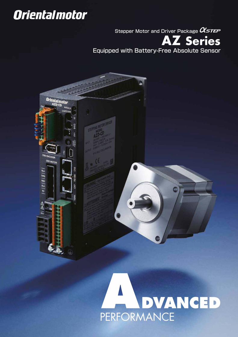
AZ SeriesEquipped with Battery-Free Absolute Sensor
ADVANCED

Absolute × Battery-FreeBrings advanced POSITIONINGclose to hand.The new AZ Series line-up achieves absolute positioning without the need for a battery.As a battery is not needed this contributes to a reduction in total cost.So the AZ Series offers absolute positioning for an affordable price.*See page 12 for details on the lineup.
PS Geared Type
HPG Geared Type
□20 mm
□28 mm
□42 mm
2

ADVANCED
Stepper Motor and Driver Package
Equipped with Battery-Free Absolute Sensor
■ Lineup
Standard Options □20 mm/□28 mm/□85 mm
Geared Options with Electromagnetic Brake □42 mm/□60 mm/□90 mm
TS Geared Type
□60 mm
□85 mm
Harmonic Geared Type
AZ Series
3

····
Speedy homing with less cabling
as external sensors no longer required.
The battery-free nature of the AZ Series
allows for easy global shipping,even with long delivery times.
Equipped with battery-free mechanical absolute sensor.
[Details on page 6] [Details on page 7]
[Details on page 8] [Details on page 9] [Details on page 10]
[Details on page 10] [Details on page 11]
Peace of mind and energy savings with our highly reliable & efficient AZ motor series.
Setup is simple due to usable functions and settings.
[Details on page 5]
Achieve a battery-free absolute system by equipping with a newly developed ABZO sensor.
Two drivers can be selected via
a master controller.
Construct a simple system
without a separate pulse generator.
Setup time is reduced due to helpful in-built
test functions.
Monitor functions allow for easy analysis of the motor running condition, facilitating
timely maintenance.
Save energy with a highly reliable and efficient motor.
4

Second handMinute hand
Hour hand
Sensor (eye)
9:00:03
We have developed a compact, low cost, battery-free mechanical absolute sensor (patented). This affordable motor series allows for productivity improvements and cost reductions.
ABZO Sensor
Battery-FreeEquipped with multirotation
absolute sensor
Push switch
・Home Position Setting
・Basic principles are like an analog clock
Newly developed ABZO sensor
● Mechanical SensorAnalog clocks measure the current time based on the positions of the second hand, minute hand and hour hand. ABZO sensor is a mechanical sensor equipped with multiple gears equivalent to the hands on a clock. As it detects positioning information by detecting the angles of the respective gears, a battery is not required.
● Multirotation Absolute SystemAbsolute position detection is possible with ±900 rotations (1800 rotations)* of the motor shaft from the home position. * The frame sizes 20 and 28 mm are ±450 rotations (900 rotations).
Equipped with a newly developed ABZO sensor, this is advanced technology at an affordable price.
● Home Position SettingBy pressing the switch on the driver sur face home position can be set simply, and the home position can be saved with the ABZO sensor. Furthermore, it is possible to set the home position using the data setting software (MEXE02) or the external input signal.
5

①②
Home Position Recorded byAZ Series
ABZO Sensor①
High Speed
The home position is detected at low speed by detecting the limit sensor (±LS) and home sensor (HOME).
There is no need to detect the limit sensor, and it moves directly at high speed to the home position recorded by the ABZO sensor.
AZ Series utilising ABZO sensor homing methodPre-ABZO homing method example
Start point
(1) Limit terminal (+LS)
(2) Home position (HOME) passed
(3) Home position (HOME) reinserted
Start point
Home position
Return-to-hometakes time ...
Through high speed return-to-home, machine cycle can be shortened!
③
-LS HOME +LS
As it is an absolute system, external sensors such as the home sensor or limit sensor are not required.
External Sensors Not Required
● High Speed Return-to-Home + Improved Return-to-Home AccuracyBecause return-to-home is possible without using an external sensor, return-to-home can be performed at high speed without taking the sensor sensitivity into account, allowing for a shortened machine cycle. Furthermore, as return-to-home can be performed without concern for differences in the home sensor, it is possible to improve home position accuracy.
Achieves a Battery-Free Absolute System.
● Cost reductions Sensor costs and cable costs can be reduced, leading to lower system costs.
● Cable savings This reduces cabling, increasing device design degree of freedom.
● Not affected by sensorThe AZ Series eliminates concerns such as sensor malfunctions, sensor faults or disconnection of the sensor lines. For example, sensor malfunctions due to metal flakes or oil mist floating about in the environment will be prevented.●In systems where limit switches are not possible, software limits can be used to prevent the limit values being exceeded.
6
ABZO sensorEmergency stop
・Overseas Shipping
AZseries
・Maintenance
Battery Type
Replace batteryevery few years
Secure space for exchanging batteries
Not necessary
Can be restarted without returning to home
Battery Type
Built-in Controller Type
AZ Series
AZ Series
Air transport
No problems with batteries
Sea transport
Location information retained even after arrival
Deployment of electrical components
Maintenance is reduced
Air transport
Necessary to confirm battery export restrictions
Sea transport
Battery discharged during transport
Need to set afterarrival again
Electrical component design
Electrical component design
Deployment of electrical components
Replacing the battery is hard work...
There are restrictions on electrical component design...
As the battery is not required, it's safe for overseas shipping!
When transporting by sea, the battery retention period is a concern...
When transporting by air, battery regulations are a concern...
Maintenance is reduced as the battery is not required!
Increases degree of freedom for electrical component design!
Free device layout
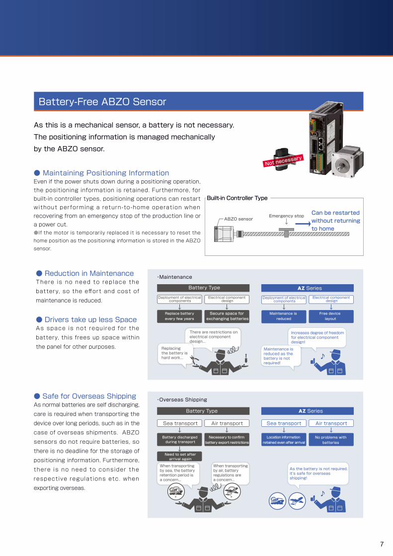
● Reduction in MaintenanceThere is no need to replace the battery, so the effort and cost of maintenance is reduced.
● Drivers take up less Space As space is not required for the battery, this frees up space within the panel for other purposes.
● Safe for Overseas ShippingAs normal batteries are self discharging, care is required when transporting the device over long periods, such as in the case of overseas shipments. ABZO sensors do not require batteries, so there is no deadline for the storage of positioning information. Furthermore, there is no need to consider the respective regulations etc. when exporting overseas.
As this is a mechanical sensor, a battery is not necessary. The positioning information is managed mechanically by the ABZO sensor.
Battery-Free ABZO Sensor
● Maintaining Positioning InformationEven if the power shuts down during a positioning operation, the positioning information is retained. Furthermore, for built-in controller types, positioning operations can restart without per forming a return-to -home operation when recovering from an emergency stop of the production line or a power cut. ●If the motor is temporarily replaced it is necessary to reset the home position as the positioning information is stored in the ABZO sensor.
? ?
7

0
200
400
600
800
1000
1200
AZ66AC-◇Conventional product
・Power consumption
Pow
er con
sumption [KWh/year]
Power consumptiondecrease of 47%
120
100
80
60
40
20
00 20 40 60 80 100 120 140 160 180Time [min]
Tempe
rature [̊ C]
Conventional product AZ66AC-◇
AZ66AC-◇Conventional product
・Temperature distribution using thermography ・ Motor surface temperature during operation under the same conditions
This is an image when driving under the same conditions.
● Keeps driving even in the case of sudden load changes or sudden accelerationNormally it drives with open loop control in sync with the pulse commands . At times of overload, control instantly switches to control using a closed loop, and perform positioning correction.
● Outputs an alarm signal in case an abnormality occursWhen overload continuously occurs, an alarm signal is output and when positioning determination is complete, a signal is output. This supports high reliability.
● Tuning not requiredAs normally it drives with open loop control, when there isa change in load, such as in the belt mechanism, cam and chain drive, the positioning can be determined without gain adjustment.
● Storing of stop position When determining positioning, it stops using the motor's own holding torque without hunting. Therefore it is suitable for use in a situation where vibration could cause a problem when stopping due to a low-rigidity mechanism.
We have adopted a proprietary control system. We have achieved high reliability by linking the benefits of open loop control and closed loop control.
High Reliability
● Reduced heat generationWe have achieved a significant decrease in heat generation through high efficiency.
● The amount of power consumption has been reduced to 47% of its previous levels through energy saving
Energy saving is also achieved by reducing motor heat generation through high efficiency.
Energy Saving
CO2 emissions have reduced by 47% compared to the previous levelsDrive conditionsRotation speed 1000 r/min, load factor 50%Usage time: 24 hour operation (drive 70%, standby 25%, stop 5%), 365 days/year
Save Energy with High Reliability and High Efficiency of
Control switches to closed mode to keep driving.
Control is performed in open mode in the same way as with a stepper motor.
Inputcounter
Deviation counter
Rotor positioncounter E
xcitation sequence
control section
Output elements
Motor
Sensor
Input signal
During overload, (position deviation is ±1.8°or more)
Normal (position deviation is less than ±1.8°)
8
Power
(1) When Controlling with I/O
Modbus (RTU)
Modbus(RTU)
I/O
Serial Communication Module
CPUCPU
Power
FA Network Module
● is a registered trademark of CC-Link Partner Association and is a registered trademark of MECHATROLINK Members Association. ● is a registered trademark for which a license is provided by Beckhoff Automation GmbH in Germany.
As the driver stores the necessary information for driving the motor, load on the host PLC can be decreased. In the case of multi-axial control, system construction can be simplified. Settings can be configured using data setting software or RS-485 communications.
Positioning Module
(2) When Controlling from a Computer or Touch Screen
(3) When Controlling with FA Network
No positioningunit required
Modbus (RTU)
FA Network
Network Converter(sold separately)
PowerPower
Pulse Signal Input
(2) When Controlling with Serial
CommunicationsCPU
Power I/OCPU
I/O
RS-485
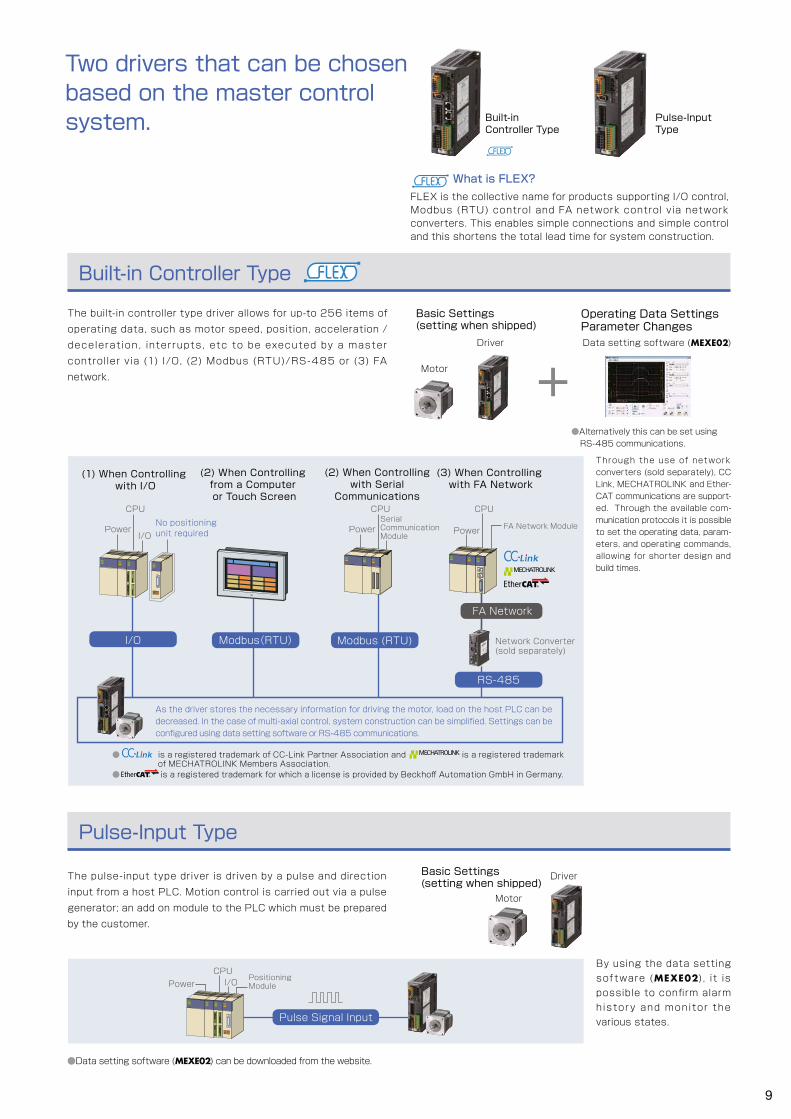
What is FLEX? FLEX is the collective name for products supporting I/O control, Modbus (RTU) control and FA network control via network converters. This enables simple connections and simple control and this shortens the total lead time for system construction.
The built-in controller type driver allows for up-to 256 items of operating data, such as motor speed, position, acceleration / deceleration, inter rupts, etc to be executed by a master controller via (1) I/O, (2) Modbus (RTU)/RS-485 or (3) FA network.
Built-in Controller Type
Through the use of network converters (sold separately), CC Link, MECHATROLINK and Ether-CAT communications are support-ed. Through the available com-munication protocols it is possible to set the operating data, param-eters, and operating commands, allowing for shorter design and build times.
Driver
Motor
Basic Settings (setting when shipped)
Operating Data SettingsParameter ChangesData setting software (MEXE02)
●Alternatively this can be set using RS-485 communications.
The pulse-input type driver is driven by a pulse and direction input from a host PLC. Motion control is carried out via a pulse generator; an add on module to the PLC which must be prepared by the customer.
Pulse-Input Type
●Data setting software (MEXE02) can be downloaded from the website.
By using the data setting software (MEXE02), it is possible to confirm alarm histor y and monitor the various states.
Driver
Motor
Basic Settings (setting when shipped)
Built-in Controller Type
Pulse-Input Type
Two drivers that can be chosen based on the master control system.
9

MEXE02
Simple status monitor
Test operation
Teaching
JOG operation
FREE operation
Simple Settings/Easy Operations
● Unit-type setting wizardThe units wizard is a function which allows the engineer to input the units they wish to work with. Thereby reducing the burden of converting units when inputing operational data.
● A simple system can be realised without a master controller.The built-in controller type driver can set and execute independently up-to 256 items of operating data, such as motor speed and index length. Furthermore, with sequential control it is possible to form a simple system without a master controller. This is ideal for index and return operations or aligned transportation, such as lifespan / durability tests.
Test Functions
By using the MEXE02 software it is possible to adjust the motor configuration and edit multiple operating and parameter settings. Furthermore, the built-in controller is able to carry out sequential control from multiple inputs or predefined interrupts without requiring a master controller.
Simple Settings and Usable Functions that could not be realized without AZ
Data setting software MEXE02
Data setting software can be downloaded from the website.
In case of questions please use our free hotline: 00800 22 55 66 22
● Teaching Remote OperationIt is possible to simply set home positions and drive the motor from the data setting software. Before connecting to the master control system, as it can per form teaching and test operations, this contributes to saving time for device startup.
● I/O TestYou can perform input signal monitoring and output signal forced output. This is a convenient function for confirming hard wiring with the master control system and the network I/O operation.
Function for driving the motor independently and with which it is possible to connect with the master control system.By using during device startup, this can help to save time.
At startup At startup When driving
10

The actual position is detected in relation to the command position.The actual speed is detected in relation to the command speed.Detects the temperature within the motor encoder part and driver.
Displays the current load rate, given that the output torque for the speed during rotation is 100%.
Monitor Function
● Waveform MonitoringIt is possible to monitor the motor driving state and output signal state in the same way as with an oscilloscope. Use this when starting up or adjusting the device.
● Status MonitoringWhen driving, it is possible to monitor speed, motor/driver temperature and load rate, as well as total revolutions from start of use. For the various items, as it is possible to set any signal to output, this is effective for efficient maintenance.
● Alarm MonitoringWhen an abnormality occurred, it is possible to confirm the content of the abnormality, driving state when it occurred, and countermeasure methods. As the countermeasure method can be confirmed, the abnormality can be handled smoothly.
Excellent monitor functions are included in order to confirm the motor driving state. Using differently based on the various scenarios helps with device startup, shortening of adjustment time and efficient maintenance.
At startup
When driving During maintenance
When driving During maintenance
11

Lineup
Motor and Driver Types
Actuator Lineup
*1 24 VDC only*2 HPG geared type is 40 mm*3 in case of geared type
We will introduce a lineup of actuators with the built-in AZ Series.
Single-Phase 100-120 VACSingle-Phase/Three-Phase 200-240 VAC24/48 VDC
ACDCACDCACDCACDCACDCACDCACDCACDCACDCACDC
ー
●*1
ー
ー
ー
ー
ー
ー
ー
ー
ー
ー
ー
ー
ー
ー
ー
ー
ー
ー
ー
●*1
ー
ー
ー
ー
ー
ー
ー
ー
ー
ー
ー
ー
ー
ー
ー
ー
ー
ー
●
●
●
●
●
●
●
●
●
●
●
●
●
●
●
●
●
●
●
●
●
●
●
●
●
●
●
●
●
●
●
●
●
●
●
●
●
●
●
●
●
ー
●
ー
●
ー
●
ー
●
ー
●
ー
●
ー
●
ー
●
ー
●
ー
Power InputElectro-magnetic Brake
Driver Type
No
Yes
No
Yes
No
Yes
No
Yes
No
Yes
Motor Type
Frame Size
20 mm 28 mm 42 mm*2 60 mm 85 mm90 mm*3
Hollow Rotary ActuatorDGⅡ Series
Frame Size85 mm, 130 mm, 200 mm
・Possible to drive at high speeds from light loads to heavy loads.・Can drive stably even at low speeds (1.25 mm/s).・Compact with high rigidity.
・Stroke: 50‒850 mm・High speed: 800 mm/s・Maximum transportable mass: 60 kg (horizontal), 30 kg (vertical)
・Stroke: 50‒850 mm・High speed: 800 mm/s・Maximum transportable mass: 60 kg (horizontal), 30 kg (vertical)
・Stroke: 50‒300 mm・High speed: 600 mm/s・Maximum transportable mass: 60 kg (horizontal), 30 kg (vertical)
・Maximum permissible torque: 50 N·m・Maximum permissible moment: 100 N·m・Maximum permissible axial load: 4000 N·m
・Compact with high rigidity.・Simple dust-proof structure.・Clean room support (ISO standard clean level class 3)
・Possible to drive at high speeds from light loads to heavy loads.・Can drive stably even at low speeds (1.25 mm/s).・Compact with high rigidity.・High thrust.
・As this is a hollow output table, wiring, such as cables and air tubes etc. is simple.・Possible to directly attach tables and arms.
Series Name Features Main Specification
TS Geared Type
Standard Type
PS Geared Type
HPG Geared Type
Harmonic Geared Type
Built-in Controller Type
Pulse-Input Type
AC Power Input
DC PowerInput
AC PowerInput
DC PowerInput
Motorized Slider EAS SeriesAZ Series Equipped
DC powerAC power
Motorized Slider EZS SeriesAZ Series Equipped
DC powerAC power
Motorized Slider EAC SeriesAZ Series Equipped
DC powerAC power
AC power
12

List Price
Function (torque/backlash)
Types and Features of Standard Types and Geared Types
● Please use the above values as reference to see the differences between each type. These values vary depending on the motor frame size and gear ratio.● Harmonic planetary, harmonic drive and are registered trademarks and trademarks of Harmonic Drive Systems Inc.
As a variation on stepper motors, we have prepared a geared motor in which the gears are combined.You can select the optimal type from among each geared motor, considering torque, accuracy (backlash) and price.
Excitation maximumstatic torque4
Permissible torqueInstantaneousmaximum torque
6000
833
70
0.0072
0.012
7
0.36
10
0.0036 052 107
Permissible torqueInstantaneousmaximum torque37 60
Permissible torqueInstantaneousmaximum torque
25 45
600
0.0243
Permissible torqueInstantaneousmaximum torque24 33 900
Permissible Torque, Instantaneous Maximum Torque
[N·m]
Basic Resolution[ /̊pulse]
Output Shaft Rotation Speed
[r/min]Backlash[arcmin]Type Features
Standard type
TS Geared Type (Spur Gear Mechanism)
PS Geared Type (Planetary Gear Mechanism)
・Good lineup of low reduction ratio types, high speed operation・Gear ratios: 3.6, 7.2, 10, 20, 30
・Permissible torque/ instantaneous maximum torque is large・Lineup of gear ratios convenient for various step angles・Center shaft・Gear ratios: 5, 7.2, 10, 25, 36, 50
・High positioning accuracy・Permissible torque/ instantaneous maximum torque is large・High gear ratio, high resolution・Center shaft・Gear ratios: 50, 100
・This is the basic AZ Series model.
Low Backlash
Non-backlash
・High positioning accuracy・Permissible torque/ instantaneous maximum torque is large・Center shaft・Gear ratios: 5, 9, 15
TS Geared Type
PS Geared Type
Harmonic Geared Type
Low price
High Torque HPG Geared Type
High TorqueHigh Accuracy
High TorqueHigh Accuracy
HPG Geared Type (Harmonic Planetary®)
Harmonic Geared Type (Harmonic Drive®)
Notes
13

14
Motor Driver
Products are available with connection cables of 1 m, 2 m or 3 m length (for motor, for encoder and for electromagnetic brake) or without cable.
Motor Mounting Brackets ➜ page 104
Cable for RS-485 Communications ➜ page 101
General-Purpose Cable for Input/Output Signals ➜ page 101
●System Configuration Example
AZ SeriesSold Separately
Motor Mounting Bracket Flexible CouplingGeneral-Purpose Cable
(1 m)AZ66MCD-3 PAL2P-5 MCV251010 CC16D010B-1
● The system configuration described above is just an example. Other combinations are available.
AZ Series
Options (sold separately)
For less vibrations When extending between the motor and driver without using attached connection cables✽2
When extending between the motor and driver using attached connection cables✽2
MCV Coupling ➜ page 102
For motor For encoder For electromagnetic
brake
For motor For encoder For electromagnetic
brake
Connection Cable Set Flexible Connection Cable Set
➜ page 96
Extension Cable Set Flexible Extension Cable Set
➜ page 97
Options (sold separately)
or
Computer✽1
To USB Port
Data Setting Software
MEXE02
(For RS-485 Communication)
Network Converter ➜ page 107
Related Products (sold separately)
■System Configuration
●Built-in Controller Type with Electromagnetic BrakeConfiguration example when using I/O control or RS-485 communications. ✽1 Prepared by the customer.
✽2 Only products to which the connection cables are attached.
For encoder
For motor
For electromagnetic brake
Programmable Controller✽1
24 VDC Power Supply for Control✽1
AC Power Supply (Main power supply)

15
Features
DC
Input
Pro
duct Line
Sp
ecifications
and F
eaturesD
imensio
nsC
onnectio
n and
Op
eration
Accesso
riesS
ystem
Co
nfiguratio
nP
rod
uct LineS
pecificatio
ns and
Features
Dim
ensions
Co
nnection
and O
peratio
n
AC
Input
System
C
onfig
uration
Motor Driver
Products are available with connection cables of 1 m, 2 m or 3 m length (for motor, for encoder and for electromagnetic brake) or without cable.
AZ series
For encoder
For motor
●System Configuration Example
AZ SeriesSold Separately
Controller Motor Mounting Bracket Flexible CouplingGeneral-Purpose Cable
(1 m)AZ66MC-3 SCX11 PAL2P-5 MCV251010 CC16D010B-1
●The system configuration described above is just an example. Other combinations are available.
Motor Mounting Bracket ➜ page 104
General-Purpose Cable for Input/Output Signals ➜ page 101
Options (sold separately)
Computer✽1
To USB Port
Data Setting Software
MEXE02
Controller ➜ page 107
Controller (sold separately)
Programmable Controller✽1
●Pulse-Input Type with Electromagnetic BrakeA single-axis system configuration with the SCX11 Series controller is shown below. ✽1 Prepared by the customer.
✽2 Only products to which the connection cables are attached.
For less vibrations When extending between the motor and driver without using attached connection cables✽2
When extending between the motor and driver using attached connection cables✽2
MCV Coupling ➜ page 102
For motor For encoder For electromagnetic
brake
For motor For encoder For electromagnetic
brake
Connection Cable Set Flexible Connection Cable Set
➜ page 96
Extension Cable Set Flexible Extension Cable Set
➜ page 97
Options (sold separately)
or
AZ Series
For electromagnetic brake
AC Power Supply (Main power supply)
24 VDC Power Supply for Control✽1
24 VDC Power Supply✽1

16
■Product Number Code
●Standard Type
① ② ③ ⑩④ ⑥⑤
AZ 6 6 A C D - 1
●Geared Types
① ② ⑧③ ⑦④ ⑥⑤ ⑨ ⑩
AZ 6 6 A C D - HP 15 F - 1
① Series Name AZ: AZ Series
② Motor Frame Size4: 42 mm (HPG Geared Type is 40 mm) 6: 60 mm 9: 85 mm (Geared Type is 90 mm)
③ Motor Case Length
④ Configuration A: Single Shaft M: With Electromagnetic Brake
⑤ Power Supply InputA: Single-Phase 100-120 VAC C: Single-Phase/Three-Phase 200-240 VAC
⑥ Driver TypeD: Built-in Controller Type None: Pulse-Input Type
⑦ Geared Type
TS: TS Geared TypePS: PS Geared TypeHP: HPG Geared TypeHS: Harmonic Geared Type
⑧ Gear Ratio
⑨ Output Shaft TypeHPG Geared Type None: Shaft Output F: Flange Output
⑩ Connection CableFigures: Included Connection Cable Length1: 1 m 2: 2 m 3: 3 mNone: Connection Cable not included
■Product Line
●Built-in Controller Type ◇Standard Type
Product Name
AZ46A ■ D-◇AZ66A ■ D-◇AZ69A ■ D-◇AZ98A ■ D-◇AZ911A ■ D-◇
◇TS Geared Type
Product Name
AZ46A ■ D-TS3.6-◇AZ46A ■ D-TS7.2-◇AZ46A ■ D-TS10-◇AZ46A ■ D-TS20-◇AZ46A ■ D-TS30-◇AZ66A ■ D-TS3.6-◇AZ66A ■ D-TS7.2-◇AZ66A ■ D-TS10-◇AZ66A ■ D-TS20-◇AZ66A ■ D-TS30-◇AZ98A ■ D-TS3.6-◇AZ98A ■ D-TS7.2-◇AZ98A ■ D-TS10-◇AZ98A ■ D-TS20-◇AZ98A ■ D-TS30-◇
◇Standard Type with Electromagnetic Brake
Product Name
AZ46M ■ D-◇AZ66M ■ D-◇AZ69M ■ D-◇AZ98M ■ D-◇
◇TS Geared Type with Electromagnetic Brake
Product Name
AZ46M ■ D-TS3.6-◇AZ46M ■ D-TS7.2-◇AZ46M ■ D-TS10-◇AZ46M ■ D-TS20-◇AZ46M ■ D-TS30-◇AZ66M ■ D-TS3.6-◇AZ66M ■ D-TS7.2-◇AZ66M ■ D-TS10-◇AZ66M ■ D-TS20-◇AZ66M ■ D-TS30-◇AZ98M ■ D-TS3.6-◇AZ98M ■ D-TS7.2-◇AZ98M ■ D-TS10-◇AZ98M ■ D-TS20-◇AZ98M ■ D-TS30-◇

17
Features
System
C
onfig
uration
DC
Input
Sp
ecifications
and F
eaturesD
imensio
nsC
onnectio
n and
Op
eration
Accesso
ries
AC
Input
System
C
onfig
uration
Pro
duct Line
Sp
ecifications
and F
eaturesD
imensio
nsC
onnectio
n and
Op
eration
Pro
duct Line
AC
Input
◇PS Geared Type
Product Name
AZ46A ■ D-PS5-◇AZ46A ■ D-PS7.2-◇AZ46A ■ D-PS10-◇AZ46A ■ D-PS25-◇AZ46A ■ D-PS36-◇AZ46A ■ D-PS50-◇AZ66A ■ D-PS5-◇AZ66A ■ D-PS7.2-◇AZ66A ■ D-PS10-◇AZ66A ■ D-PS25-◇AZ66A ■ D-PS36-◇AZ66A ■ D-PS50-◇AZ98A ■ D-PS5-◇AZ98A ■ D-PS7.2-◇AZ98A ■ D-PS10-◇AZ98A ■ D-PS25-◇AZ98A ■ D-PS36-◇AZ98A ■ D-PS50-◇
◇HPG Geared Type
Product Name
AZ46A ■ D-HP5-◇AZ46A ■ D-HP5F-◇AZ46A ■ D-HP9-◇AZ46A ■ D-HP9F-◇AZ66A ■ D-HP5-◇AZ66A ■ D-HP5F-◇AZ66A ■ D-HP15-◇AZ66A ■ D-HP15F-◇AZ98A ■ D-HP5-◇AZ98A ■ D-HP5F-◇AZ98A ■ D-HP15-◇AZ98A ■ D-HP15F-◇
◇Harmonic Geared Type
Product Name
AZ46A ■ D-HS50-◇AZ46A ■ D-HS100-◇AZ66A ■ D-HS50-◇AZ66A ■ D-HS100-◇AZ98A ■ D-HS50-◇AZ98A ■ D-HS100-◇
◇PS Geared Type with Electromagnetic Brake
Product Name
AZ46M ■ D-PS5-◇AZ46M ■ D-PS7.2-◇AZ46M ■ D-PS10-◇AZ46M ■ D-PS25-◇AZ46M ■ D-PS36-◇AZ46M ■ D-PS50-◇AZ66M ■ D-PS5-◇AZ66M ■ D-PS7.2-◇AZ66M ■ D-PS10-◇AZ66M ■ D-PS25-◇AZ66M ■ D-PS36-◇AZ66M ■ D-PS50-◇AZ98M ■ D-PS5-◇AZ98M ■ D-PS7.2-◇AZ98M ■ D-PS10-◇AZ98M ■ D-PS25-◇AZ98M ■ D-PS36-◇AZ98M ■ D-PS50-◇
◇HPG Geared Type with Electromagnetic Brake
Product Name
AZ46M ■ D-HP5-◇AZ46M ■ D-HP5F-◇AZ46M ■ D-HP9-◇AZ46M ■ D-HP9F-◇AZ66M ■ D-HP5-◇AZ66M ■ D-HP5F-◇AZ66M ■ D-HP15-◇AZ66M ■ D-HP15F-◇AZ98M ■ D-HP5-◇AZ98M ■ D-HP5F-◇AZ98M ■ D-HP15-◇AZ98M ■ D-HP15F-◇
◇Harmonic Geared Type with Electromagnetic Brake
Product Name
AZ46M ■ D-HS50-◇AZ46M ■ D-HS100-◇AZ66M ■ D-HS50-◇AZ66M ■ D-HS100-◇AZ98M ■ D-HS50-◇AZ98M ■ D-HS100-◇
●Either A (single-phase 100-120 VAC) or C (single-phase/three-phase 200-240 VAC) indicating power supply input is entered where the box ■ is located within the product name.A number indicating the desired length of 1 (1 m), 2 (2 m) or 3 (3 m) is entered where the box ◇ is located within the product name when the cable is included with the product.
The following items are included in each product.
Motor, Parallel Key✽1, Motor Installation Screws ✽2, Driver, Cable for Motor✽3, Cable for Encoder✽3, Cable for Electromagnetic Brake (units with electromagnetic brake only) ✽3, Driver Connector Set and Operating Manual
✽1 Only for products with a key slot on the output shaft. ✽2 TS geared type with frame sizes 60 mm and 90 mm only. ✽3 Only products where connection cables are included. Accessory cables (sold separately) must be purchased in the following situations:∙ When using a flexible cable∙ When using a cable longer than 3 m∙ When purchasing a product to without cable
Notes ●The motor cable and electromagnetic brake cable from the motor cannot be connected directly to the driver. When connecting to a driver, use the accessory connection cable (sold separately) or use the included connection cable.

18
●Pulse-Input Type ◇Standard Type
Product Name
AZ46A ■ -◇AZ66A ■ -◇AZ69A ■ -◇AZ98A ■ -◇AZ911A ■ -◇
◇TS Geared Type
Product Name
AZ46A ■ -TS3.6-◇AZ46A ■ -TS7.2-◇AZ46A ■ -TS10-◇AZ46A ■ -TS20-◇AZ46A ■ -TS30-◇AZ66A ■ -TS3.6-◇AZ66A ■ -TS7.2-◇AZ66A ■ -TS10-◇AZ66A ■ -TS20-◇AZ66A ■ -TS30-◇AZ98A ■ -TS3.6-◇AZ98A ■ -TS7.2-◇AZ98A ■ -TS10-◇AZ98A ■ -TS20-◇AZ98A ■ -TS30-◇
◇PS Geared Type
Product Name
AZ46A ■ -PS5-◇AZ46A ■ -PS7.2-◇AZ46A ■ -PS10-◇AZ46A ■ -PS25-◇AZ46A ■ -PS36-◇AZ46A ■ -PS50-◇AZ66A ■ -PS5-◇AZ66A ■ -PS7.2-◇AZ66A ■ -PS10-◇AZ66A ■ -PS25-◇AZ66A ■ -PS36-◇AZ66A ■ -PS50-◇AZ98A ■ -PS5-◇AZ98A ■ -PS7.2-◇AZ98A ■ -PS10-◇AZ98A ■ -PS25-◇AZ98A ■ -PS36-◇AZ98A ■ -PS50-◇
◇Standard Type with Electromagnetic Brake
Product Name
AZ46M ■ -◇AZ66M ■ -◇AZ69M ■ -◇AZ98M ■ -◇
◇TS Geared Type with Electromagnetic Brake
Product Name
AZ46M ■ -TS3.6-◇AZ46M ■ -TS7.2-◇AZ46M ■ -TS10-◇AZ46M ■ -TS20-◇AZ46M ■ -TS30-◇AZ66M ■ -TS3.6-◇AZ66M ■ -TS7.2-◇AZ66M ■ -TS10-◇AZ66M ■ -TS20-◇AZ66M ■ -TS30-◇AZ98M ■ -TS3.6-◇AZ98M ■ -TS7.2-◇AZ98M ■ -TS10-◇AZ98M ■ -TS20-◇AZ98M ■ -TS30-◇
◇PS Geared Type with Electromagnetic Brake
Product Name
AZ46M ■ -PS5-◇AZ46M ■ -PS7.2-◇AZ46M ■ -PS10-◇AZ46M ■ -PS25-◇AZ46M ■ -PS36-◇AZ46M ■ -PS50-◇AZ66M ■ -PS5-◇AZ66M ■ -PS7.2-◇AZ66M ■ -PS10-◇AZ66M ■ -PS25-◇AZ66M ■ -PS36-◇AZ66M ■ -PS50-◇AZ98M ■ -PS5-◇AZ98M ■ -PS7.2-◇AZ98M ■ -PS10-◇AZ98M ■ -PS25-◇AZ98M ■ -PS36-◇AZ98M ■ -PS50-◇

19
Features
System
C
onfig
uration
DC
Input
Sp
ecifications
and F
eaturesD
imensio
nsC
onnectio
n and
Op
eration
Accesso
ries
AC
Input
System
C
onfig
uration
Pro
duct Line
Sp
ecifications
and F
eaturesD
imensio
nsC
onnectio
n and
Op
eration
Pro
duct Line
AC
Input
◇HPG Geared Type
Product Name
AZ46A ■ -HP5-◇AZ46A ■ -HP5F-◇AZ46A ■ -HP9-◇AZ46A ■ -HP9F-◇AZ66A ■ -HP5-◇AZ66A ■ -HP5F-◇AZ66A ■ -HP15-◇AZ66A ■ -HP15F-◇AZ98A ■ -HP5-◇AZ98A ■ -HP5F-◇AZ98A ■ -HP15-◇AZ98A ■ -HP15F-◇
◇Harmonic Geared Type
Product Name
AZ46A ■ -HS50-◇AZ46A ■ -HS100-◇AZ66A ■ -HS50-◇AZ66A ■ -HS100-◇AZ98A ■ -HS50-◇AZ98A ■ -HS100-◇
◇HPG Geared Type with Electromagnetic Brake
Product Name
AZ46M ■ -HP5-◇AZ46M ■ -HP5F-◇AZ46M ■ -HP9-◇AZ46M ■ -HP9F-◇AZ66M ■ -HP5-◇AZ66M ■ -HP5F-◇AZ66M ■ -HP15-◇AZ66M ■ -HP15F-◇AZ98M ■ -HP5-◇AZ98M ■ -HP5F-◇AZ98M ■ -HP15-◇AZ98M ■ -HP15F-◇
◇Harmonic Geared Type with Electromagnetic Brake
Product Name
AZ46M ■ -HS50-◇AZ46M ■ -HS100-◇AZ66M ■ -HS50-◇AZ66M ■ -HS100-◇AZ98M ■ -HS50-◇AZ98M ■ -HS100-◇
●Either A (single-phase 100-120 VAC) or C (single-phase/three-phase 200-240 VAC) indicating power supply input is entered where the box ■ is located within the product name.A number indicating the desired length of 1 (1 m), 2 (2 m) or 3 (3 m) is entered where the box ◇ is located within the product name when the cable is included with the product.
The following items are included in each product.
Motor, Parallel Key✽1, Motor Installation Screws ✽2, Driver, Cable for Motor✽3, Cable for Encoder✽3, Cable for Electromagnetic Brake (units with electromagnetic brake only) ✽3, Driver Connector Set and Operating Manual
✽1 Only for products with a key slot on the output shaft. ✽2 TS geared type with frame sizes 60 mm and 90 mm only. ✽3 Only products where connection cables are included. Accessory cables (sold separately) must be purchased in the following situations:∙ When using a flexible cable∙ When using a cable longer than 3 m∙ When purchasing a product to without cable
Notes ●The motor cable and electromagnetic brake cable from the motor cannot be connected directly to the driver. When connecting to a driver, use the accessory connection cable (sold separately) or use the included connection cable.
■How to read the specification table
Maximum Holding Torque : This is the maximum holding torque (holding force) the motor has when power is supplied (at rated current) but the motor is not rotating. (With geared types, the value of holding torque considers the permissible strength of the gear).
Permissible torque : This is the maximum torque value continuously applied to the gear output shaft.
Instantaneous maximum torque : This is the maximum torque value applied to the gear output shaft when accelerating and decelerating such as when starting/stopping inertial load.
Holding torque at standstill While power on : This is the holding torque in the state in which the automatic current down function is working. Electromagnetic brakes : Static friction torque that can be caused by the electromagnetic brakes when stopped. (Electromagnetic brakes are non-excitation actuating type.)

20
Standard Type Frame Size 42 mm, 60 mm, 85 mm
■Specifications
Product NameBuilt-in Controller Type AZ46 □ ■D-◇ AZ66 □ ■D-◇ AZ69 □ ■D-◇ AZ98 □ ■ D-◇ AZ911A ■ D-◇
Pulse-Input Type AZ46 □ ■-◇ AZ66 □ ■-◇ AZ69 □ ■-◇ AZ98 □ ■ -◇ AZ911A ■-◇
Maximum Holding Torque N·m 0.3 1.2 2 2 4
Holding Torque at Motor Standstill
Power ON N·m 0.15 0.6 1 1 2
Electromagnetic Brake N·m 0.15 0.6 1 1 –
Rotor Inertia J: kg·m2 55×10-7
(71×10-7)✽1370×10-7
(530×10-7)✽1740×10-7
(900×10-7)✽11090×10-7
(1250×10-7) ✽1 2200×10-7
ResolutionResolution Setting: 1000P/
R 0.36°/Pulse
Power Supply Input
Voltage/Frequency Single-Phase 100-120 VAC, Single-Phase/Three-Phase 200-240 VAC −15∼+6% 50/60 Hz
Input current A
Single-Phase 100–120 VAC 2.7 3.8 5.4 5.5 6.4
Single Phase 200–240 VAC 1.7 2.3 3.3 3.3 3.9
Three Phase 200–240 VAC 1.0 1.4 2.0 2.0 2.3
Control Power Supply24 VDC ±5%✽2 0.25 A (0.33 A)✽1 24 VDC ±5%✽2 0.25 A (0.5 A)✽1
Either A (single shaft) or M (electromagnetic brake) indicating the configuration is entered where the box □ is located within the product name. Either A (single-phase 100-120 VAC) or C (single-phase/three-phase 200-240 VAC) indicating the power supply input is entered where the box ■ is located within the product name.A number indicating the desired length of 1 (1 m), 2 (2 m) or 3 (3 m) is entered where the box ◇ is located within the product name when the cable is included with the product.
✽1 The values inside the brackets ( ) represent the specification for the electromagnetic brake type. ✽2 If the wiring distance between the electromagnetic brake type motor and driver is extended to 20 m using an accessory cable (sold separately), the 24 VDC±4%
specification applies.
■Speed - Torque Characteristics (Reference Value)
AZ46 AZ66 AZ69
0 2010 4030 50 60 70
0 1000 2000 40003000
0.4
0.3
0.2
0.1
05000
80 Pulse Speed [kHz]
Resolution Setting:1000P/R
Speed [r/min]
Torq
ue [ N
·m]
0 2010 4030 50 60 70
0 1000 2000 40003000
1.5
0.5
05000
80
1.0
Pulse Speed [kHz]Resolution Setting:1000P/R
Speed [r/min]
Torq
ue [ N
·m]
0 2010 4030 50 60 70
0 1000 2000 40003000
3
1
05000
80
2
Pulse Speed [kHz]Resolution Setting:1000P/R
Speed [r/min]
Torq
ue [ N
·m]
AZ98 AZ911
0 2010 4030 50 60 70
0 1000 2000 40003000
3
1
0 5000
80
2
Pulse Speed [kHz]Resolution Setting: 1000P/R
Speed [r/min]
Torq
ue [ N
·m]
0 2010 4030 50 60 70
0 1000 2000 40003000
5
1
0 5000
80
2
3
4
Pulse Speed [kHz]Resolution Setting: 1000P/R
Speed [r/min]
Torq
ue [ N
·m]
Notes ●The speed-torque characteristics are data based upon our measurement conditions. When these conditions change, these characteristics may change. ●Depending on the driving conditions, a considerable amount of heat may be generated by the motor. Be sure to keep the motor case temperature at 80°C or less in order to protect the ABZO sensor. (When conforming to the UL standards, it is required to keep the temperature of the motor case at 75°C or less, since the motor is recognized as thermal class A.)

21
Features
System
C
onfig
uration
DC
Input
Pro
duct Line
Dim
ensions
Co
nnection
and O
peratio
nA
ccessories
AC
Input
System
C
onfig
uration
Pro
duct Line
Sp
ecifications
and F
eaturesD
imensio
nsC
onnectio
n and
Op
eration
Sp
ecifications
and F
eatures
AC
Input
TS Geared Type Frame Size 42 mm
■Specifications
Product NameBuilt-in Controller Type AZ46 □ ■ D-TS3.6-◇ AZ46 □ ■ D-TS7.2-◇ AZ46 □ ■ D-TS10-◇ AZ46 □ ■ D-TS20-◇ AZ46 □ ■ D-TS30-◇
Pulse-Input Type AZ46 □ ■ -TS3.6-◇ AZ46 □ ■ -TS7.2-◇ AZ46 □ ■ -TS10-◇ AZ46 □ ■ -TS20-◇ AZ46 □ ■ -TS30-◇
Maximum Holding Torque N·m 0.65 1.2 1.7 2 2.3
Rotor Inertia J: kg·m2 55×10-7 (71×10-7)✽1
Gear Ratio 3.6 7.2 10 20 30
Resolution Resolution Setting: 1000P/R 0.1˚/Pulse 0.05˚/Pulse 0.036˚/Pulse 0.018˚/Pulse 0.012˚/Pulse
Permissible Torque N·m 0.65 1.2 1.7 2 2.3
Instantaneous Maximum Torque N·m 0.85 1.6 2 3
Holding Torque at Motor Standstill
Power ON N·m 0.54 1 1.5 1.9 2.2
Electromagnetic Brake N·m 0.54 1 1.5 1.9 2.2
Speed Range r/min 0∼833 0∼416 0∼300 0∼150 0∼100
Backlash arcmin 45 (0.75˚) 25 (0.42˚) 15 (0.25˚)
Power Supply Input
Voltage/Frequency Single-Phase 100-120 VAC, Single-Phase/Three-Phase 200-240 VAC −15∼+6% 50/60 Hz
Input current A
Single-Phase 100-120 VAC 2.7
Single Phase 200–240 VAC 1.7
Three Phase 200–240 VAC 1.0
Control Power Supply 24 VDC ±5%✽2 0.25 A (0.33 A)✽1
Either A (single shaft) or M (electromagnetic brake) indicating the configuration is entered where the box □ is located within the product name. Either A (single-phase 100-120 VAC) or C (single-phase/three-phase 200-240 VAC) indicating the power supply input is entered where the box ■ is located within the product name. A number indicating the desired length of 1 (1 m), 2 (2 m) or 3 (3 m) is entered where the box ◇ is located within the product name when the cable is included with the product. ●Check the website for detailed information on the specification.
✽1 The values inside the brackets ( ) represent the specification for the electromagnetic brake type. ✽2 If the wiring distance between the electromagnetic brake type motor and driver is extended to 20 m using an accessory cable (sold separately), the 24 VDC±4%
specification applies.
■Speed - Torque Characteristics (Reference Value)
AZ46 Gear Ratio 3.6 AZ46 Gear Ratio 7.2 AZ46 Gear Ratio 10
0
1.0
0.2
0.8
0.6
0.4
0 200 800400 600
0 20 3010 40 50
Permissible torque
Instantaneous maximum torque
Speed [r/min]
Pulse Speed [kHz]Resolution Setting: 1000P/R
Torq
ue [ N
∙m]
0
2.0
1.5
1.0
0.5
0 100 400200 300
0 20 3010 40 50
Speed [r/min]
Pulse Speed [kHz]Resolution Setting: 1000P/R
Torq
ue [ N
∙m] Permissible torque
Instantaneous maximum torque
0
2.5
2.0
1.5
1.0
0.5
0 100 200 300
0 20 3010 40 50
Permissible torque
Instantaneous maximum torque
Speed [r/min]
Pulse Speed [kHz]Resolution Setting: 1000P/R
Torq
ue [ N
∙m]
AZ46 Gear Ratio 20 AZ46 Gear Ratio 30
0
4
3
2
1
0 50 100 150
0 20 3010 40 50
Speed [r/min]
Pulse Speed [kHz]Resolution Setting:1000P/R
Torq
ue [ N
∙m]
Permissible torque
Instantaneous maximum torque
0
4
3
2
1
0 40 60 8020 100 120
0 20 3010 40 50 60 Pulse Speed [kHz]
Resolution Setting:1000P/R
Torq
ue [ N
∙m]
Permissible torque
Instantaneous maximum torque
Speed [r/min]
Notes ●The speed-torque characteristics are data based upon our measurement conditions. When these conditions change, these characteristics may change. ●Depending on the driving conditions, a considerable amount of heat may be generated by the motor. Be sure to keep the motor case temperature at 80°C or less in order to protect the ABZO sensor. (When conforming to the UL standards, it is required to keep the temperature of the motor case at 75°C or less, since the motor is recognized as thermal class A.)

22
TS Geared Type Frame Size 60 mm
■Specifications
Product NameBuilt-in Controller Type AZ66 □ ■ D-TS3.6-◇ AZ66 □ ■ D-TS7.2-◇ AZ66 □ ■ D-TS10-◇ AZ66 □ ■ D-TS20-◇ AZ66 □ ■ D-TS30-◇
Pulse-Input Type AZ66 □ ■ -TS3.6-◇ AZ66 □ ■ -TS7.2-◇ AZ66 □ ■ -TS10-◇ AZ66 □ ■ -TS20-◇ AZ66 □ ■ -TS30-◇
Maximum Holding Torque N·m 1.8 3 4 5 6
Rotor Inertia J: kg·m2 370×10-7 (530×10-7)✽1
Gear Ratio 3.6 7.2 10 20 30
Resolution Resolution Setting: 1000P/R 0.1˚/Pulse 0.05˚/Pulse 0.036˚/Pulse 0.018˚/Pulse 0.012˚/Pulse
Permissible Torque N·m 1.8 3 4 5 6
Instantaneous Maximum Torque✽ N·m ✽ 4.5 6 8 10
Holding Torque at Motor Standstill
Power ON N·m 1.3 2.6 3.7 5 6
Electromagnetic Brake N·m 1.3 2.6 3.7 5 6
Speed Range r/min 0∼833 0∼416 0∼300 0∼150 0∼100
Backlash arcmin 35 (0.59˚) 15 (0.25˚) 10 (0.17˚)
Power Supply Input
Voltage/Frequency Single-Phase 100-120 VAC, Single-Phase/Three-Phase 200-240 VAC −15∼+6% 50/60 Hz
Input current A
Single-Phase 100-120 VAC 3.8
Single Phase 200–240 VAC 2.3
Three Phase 200–240 VAC 1.4
Control Power Supply 24 VDC ±5%✽2 0.25 A (0.5 A)✽1
✽For the output torque as a geared motor, see the speed-torque characteristics. ●Either A (single shaft) or M (electromagnetic brake) indicating the configuration is entered where the box □ is located within the product name. Either A (single-phase 100-120 VAC) or C (single-phase/three-phase 200-240 VAC) indicating the power supply input is entered where the box ■ is located within the product name.A number indicating the desired length of 1 (1 m), 2 (2 m) or 3 (3 m) is entered where the box ◇ is located within the product name when the cable is included with the product. ●Check the website for detailed information on the specification.
✽1 The values inside the brackets ( ) represent the specification for the electromagnetic brake type. ✽2 If the wiring distance between the electromagnetic brake type motor and driver is extended to 20 m using an accessory cable (sold separately), the 24 VDC±4%
specification applies.
■Speed - Torque Characteristics (Reference Value)
AZ66 Gear Ratio 3.6 AZ66 Gear Ratio 7.2 AZ66 Gear Ratio 10
0
3.0
0.5
2.0
2.5
1.5
1.0
0 200 800400 600
0 20 3010 40 50
Permissible torque
Speed [r/min]
Pulse Speed [kHz]Resolution Setting: 1000P/R
Torq
ue [ N
∙m]
0 100 400200 3000
6
1
4
5
3
2
0 20 3010 40 50
Speed [r/min]
Pulse Speed [kHz]Resolution Setting: 1000P/R
Torq
ue [ N
∙m]
Permissible torque
Instantaneous maximum torque
0 100 200 300
0 20 3010 40 50
0
8
2
6
4Permissible torque
Instantaneous maximum torque
Speed [r/min]
Pulse Speed [kHz]Resolution Setting: 1000P/R
Torq
ue [ N
∙m]
AZ66 Gear Ratio 20 AZ66 Gear Ratio 30
0
10
6
8
4
2
0 50 100 150
0 20 3010 40 50
Speed [r/min]
Pulse Speed [kHz]Resolution Setting: 1000P/R
Torq
ue [ N
∙m]
Permissible torque
Instantaneous maximum torque
0 40 60 8020 100 120
0 20 3010 40 50 60
0
12
2
8
10
6
4
Pulse Speed [kHz]Resolution Setting: 1000P/R
Permissible torque
Instantaneous maximum torque
Torq
ue [ N
∙m]
Speed [r/min]
Notes ●The speed-torque characteristics are data based upon our measurement conditions. When these conditions change, these characteristics may change. ●Depending on the driving conditions, a considerable amount of heat may be generated by the motor. Be sure to keep the motor case temperature at 80°C or less in order to protect the ABZO sensor. (When conforming to the UL standards, it is required to keep the temperature of the motor case at 75°C or less, since the motor is recognized as thermal class A.)

23
Features
System
C
onfig
uration
DC
Input
Pro
duct Line
Dim
ensions
Co
nnection
and O
peratio
nA
ccessories
AC
Input
System
C
onfig
uration
Pro
duct Line
Sp
ecifications
and F
eaturesD
imensio
nsC
onnectio
n and
Op
eration
Sp
ecifications
and F
eatures
AC
Input
TS Geared Type Frame Size 90 mm
■Specifications
Product NameBuilt-in Controller Type AZ98 □ ■ D-TS3.6-◇ AZ98 □ ■ D-TS7.2-◇ AZ98 □ ■ D-TS10-◇ AZ98 □ ■ D-TS20-◇ AZ98 □ ■ D-TS30-◇
Pulse-Input Type AZ98 □ ■ -TS3.6-◇ AZ98 □ ■ -TS7.2-◇ AZ98 □ ■ -TS10-◇ AZ98 □ ■ -TS20-◇ AZ98 □ ■ -TS30-◇
Maximum Holding Torque N·m 6 10 14 20 25
Rotor Inertia J: kg·m2 1090×10-7 (1250×10-7)✽1
Gear Ratio 3.6 7.2 10 20 30
Resolution Resolution Setting: 1000P/R 0.1˚/Pulse 0.05˚/Pulse 0.036˚/Pulse 0.018˚/Pulse 0.012˚/Pulse
Permissible Torque N·m 6 10 14 20 25
Instantaneous Maximum Torque✽ N·m ✽ ✽ 20 ✽ 45
Holding Torque at Motor Standstill
Power ON N·m 3.6 7.2 10 20 25
Electromagnetic Brake N·m 3.6 7.2 10 20 25
Speed Range r/min 0∼833 0∼416 0∼300 0∼150 0∼100
Backlash arcmin 25 (0.42˚) 15 (0.25˚) 10 (0.17˚)
Power Supply Input
Voltage/Frequency Single-Phase 100-120 VAC, Single-Phase/Three-Phase 200-240 VAC −15∼+6% 50/60 Hz
Input current A
Single-Phase 100-120 VAC 5.5
Single Phase 200–240 VAC 3.3
Three Phase 200–240 VAC 2.0
Control Power Supply 24 VDC ±5%✽2 0.25 A (0.5 A)✽1
✽For the output torque as a geared motor, see the speed-torque characteristics.Either A (single shaft) or M (electromagnetic brake) indicating the configuration is entered where the box □ is located within the product name. Either A (single-phase 100-120 VAC) or C (single-phase/three-phase 200-240 VAC) indicating the power supply input is entered where the box ■ is located within the product name. A number indicating the desired length of 1 (1 m), 2 (2 m) or 3 (3 m) is entered where the box ◇ is located within the product name when the cable is included with the product. ●Check the website for detailed information on the specification.
✽1 The values inside the brackets ( ) represent the specification for the electromagnetic brake type. ✽2 If the wiring distance between the electromagnetic brake type motor and driver is extended to 20 m using an accessory cable (sold separately), the 24 VDC±4%
specification applies.
■Speed - Torque Characteristics (Reference Value)
AZ98 Gear Ratio 3.6 AZ98 Gear Ratio 7.2 AZ98 Gear Ratio 10
0
10
2
6
8
4
0 200 800400 600
0 20 3010 40 50
Permissible torque
Speed [r/min]
Pulse Speed [kHz]Resolution Setting: 1000P/R
Torq
ue [ N
∙m]
0 100 400200 3000
16
2
4
10
12
14
8
6
0 20 3010 40 50
Speed [r/min]
Pulse Speed [kHz]Resolution Setting: 1000P/R
Torq
ue [ N
∙m]
Permissible torque
0 100 200 300
0 20 3010 40 50
0
25
5
15
20
10 Permissible torque
Instantaneous maximum torque
Speed [r/min]
Pulse Speed [kHz]Resolution Setting: 1000P/R
Torq
ue [ N
∙m]
AZ98 Gear Ratio 20 AZ98 Gear Ratio 30
0
40
25
30
35
15
20
5
10
0 50 100 150
0 20 3010 40 50
Speed [r/min]
Pulse Speed [kHz]Resolution Setting: 1000P/R
Torq
ue [ N
∙m]
Permissible torque
0 40 60 8020 100 120
0 20 3010 40 50 60
0
60
10
40
50
30
20
Pulse Speed [kHz]Resolution Setting: 1000P/R
Permissible torque
Instantaneous maximum torque
Torq
ue [ N
∙m]
Speed [r/min]
Notes ●The speed-torque characteristics are data based upon our measurement conditions. When these conditions change, these characteristics may change. ●Depending on the driving conditions, a considerable amount of heat may be generated by the motor. Be sure to keep the motor case temperature at 80°C or less in order to protect the ABZO sensor. (When conforming to the UL standards, it is required to keep the temperature of the motor case at 75°C or less, since the motor is recognized as thermal class A.)

24
PS Geared Type Frame Size 42 mm
■Specifications
Product NameBuilt-in Controller Type AZ46 □ ■ D-PS5-◇ AZ46 □ ■ D-PS7.2-◇ AZ46 □ ■ D-PS10-◇ AZ46 □ ■ D-PS25-◇ AZ46 □ ■ D-PS36-◇ AZ46 □ ■ D-PS50-◇
Pulse-Input Type AZ46 □ ■ -PS5-◇ AZ46 □ ■ -PS7.2-◇ AZ46 □ ■ -PS10-◇ AZ46 □ ■ -PS25-◇ AZ46 □ ■ -PS36-◇ AZ46 □ ■ -PS50-◇
Maximum Holding Torque N·m 1 1.5 2.5 3
Rotor Inertia J: kg·m2 55×10-7 (71×10-7)✽1
Gear Ratio 5 7.2 10 25 36 50
Resolution Resolution Setting: 1000P/R 0.072˚/Pulse 0.05˚/Pulse 0.036˚/Pulse 0.0144˚/Pulse 0.01˚/Pulse 0.0072˚/Pulse
Permissible Torque N·m 1 1.5 2.5 3
Instantaneous Maximum Torque N·m 1.5 2 6
Holding Torque at Motor Standstill
Power ON N·m 0.75 1 1.5 2.5 3
Electromagnetic Brake N·m 0.75 1 1.5 2.5 3
Speed Range r/min 0∼600 0∼416 0∼300 0∼120 0∼83 0∼60
Backlash arcmin 15 (0.25˚)
Power Supply Input
Voltage/Frequency Single-Phase 100-120 VAC, Single-Phase/Three-Phase 200-240 VAC −15∼+6% 50/60 Hz
Input current A
Single-Phase 100-120 VAC 2.7
Single Phase 200–240 VAC 1.7
Three Phase 200–240 VAC 1.0
Control Power Supply 24 VDC ±5%✽2 0.25 A (0.33 A)✽1
●Either A (single shaft) or M (electromagnetic brake) indicating the configuration is entered where the box □ is located within the product name. Either A (single-phase 100-120 VAC) or C (single-phase/three-phase 200-240 VAC) indicating the power supply input is entered where the box ■ is located within the product name. A number indicating the desired length of 1 (1 m), 2 (2 m) or 3 (3 m) is entered where the box ◇ is located within the product name when the cable is included with the product. ●Check the website for detailed information on the specification.
✽1 The values inside the brackets ( ) represent the specification for the electromagnetic brake type. ✽2 If the wiring distance between the electromagnetic brake type motor and driver is extended to 20 m using an accessory cable (sold separately), the 24 VDC±4%
specification applies.
■Speed - Torque Characteristics (Reference Value)
AZ46 Gear Ratio 5 AZ46 Gear Ratio 7.2 AZ46 Gear Ratio 10
0
2.0
1.5
1.0
0.5
0 200 300 400100 500 600 700
0 20 3010 40 50 Pulse Speed [kHz]
Resolution Setting: 1000P/R
Torq
ue [ N
∙m]
Speed [r/min]
Permissible torque
Instantaneous maximum torque
0
2.5
2.0
1.5
1.0
0.5
0 200 300 400100 500
0 20 3010 40 50 60 Pulse Speed [kHz]
Resolution Setting: 1000P/R
Torq
ue [ N
∙m]
Speed [r/min]
Permissible torque
Instantaneous maximum torque
00 100 200 300
0 20 3010 40 50
2.5
2.0
1.5
1.0
0.5
Pulse Speed [kHz]Resolution Setting: 1000P/R
Torq
ue [ N
∙m]
Speed [r/min]
Permissible torque
Instantaneous maximum torque
AZ46 Gear Ratio 25 AZ46 Gear Ratio 36 AZ46 Gear Ratio 50
00 50 100 150
0 20 3010 40 50 60
8
6
4
2
Pulse Speed [kHz]Resolution Setting: 1000P/R
Torq
ue [ N
∙m]
Speed [r/min]
Permissible torque
Instantaneous maximum torque
0 4020 60 80 100
0 20 3010 40 50 60
0
8
6
4
2
Pulse Speed [kHz]Resolution Setting: 1000P/R
Speed [r/min]
Torq
ue [ N
∙m]
Permissible torque
Instantaneous maximum torque
0 20 30 4010 50 60 70
0 20 3010 40 50
0
8
6
4
2
Pulse Speed [kHz]Resolution Setting: 1000P/R
Speed [r/min]
Torq
ue [ N
∙m]
Permissible torque
Instantaneous maximum torque
Notes ●The speed-torque characteristics are data based upon our measurement conditions. When these conditions change, these characteristics may change. ●Depending on the driving conditions, a considerable amount of heat may be generated by the motor. Be sure to keep the motor case temperature at 80°C or less in order to protect the ABZO sensor. (When conforming to the UL standards, it is required to keep the temperature of the motor case at 75°C or less, since the motor is recognized as thermal class A.)

25
Features
System
C
onfig
uration
DC
Input
Pro
duct Line
Dim
ensions
Co
nnection
and O
peratio
nA
ccessories
AC
Input
System
C
onfig
uration
Pro
duct Line
Sp
ecifications
and F
eaturesD
imensio
nsC
onnectio
n and
Op
eration
Sp
ecifications
and F
eatures
AC
Input
PS Geared Type Frame Size 60 mm
■Specifications
Product NameBuilt-in Controller Type AZ66 □ ■ D-PS5-◇ AZ66 □ ■ D-PS7.2-◇ AZ66 □ ■ D-PS10-◇ AZ66 □ ■ D-PS25-◇ AZ66 □ ■ D-PS36-◇ AZ66 □ ■ D-PS50-◇
Pulse-Input Type AZ66 □ ■ -PS5-◇ AZ66 □ ■ -PS7.2-◇ AZ66 □ ■ -PS10-◇ AZ66 □ ■ -PS25-◇ AZ66 □ ■ -PS36-◇ AZ66 □ ■ -PS50-◇
Maximum Holding Torque N·m 3.5 4 5 8
Rotor Inertia J: kg·m2 370×10-7 (530×10-7)✽1
Gear Ratio 5 7.2 10 25 36 50
Resolution Resolution Setting: 1000P/R 0.072˚/Pulse 0.05˚/Pulse 0.036˚/Pulse 0.0144˚/Pulse 0.01˚/Pulse 0.0072˚/Pulse
Permissible Torque N·m 3.5 4 5 8
Instantaneous Maximum Torque✽ N·m ✽ ✽ 11 16 20
Holding Torque at Motor Standstill
Power ON N·m 3 4 5 8
Electromagnetic Brake N·m 3 4 5 8
Speed Range r/min 0∼600 0∼416 0∼300 0∼120 0∼83 0∼60
Backlash arcmin 7 (0.12˚) 9 (0.15˚)
Power Supply Input
Voltage/Frequency Single-Phase 100-120 VAC, Single-Phase/Three-Phase 200-240 VAC −15∼+6% 50/60 Hz
Input current A
Single-Phase 100-120 VAC 3.8
Single Phase 200–240 VAC 2.3
Three Phase 200–240 VAC 1.4
Control Power Supply 24 VDC ±5%✽2 0.25 A (0.5 A)✽1
✽For the output torque as a geared motor, see the speed-torque characteristics.Either A (single shaft) or M (electromagnetic brake) indicating the configuration is entered where the box □ is located within the product name. Either A (single-phase 100-120 VAC) or C (single-phase/three-phase 200-240 VAC) indicating the power supply input is entered where the box ■ is located within the product name. A number indicating the desired length of 1 (1 m), 2 (2 m) or 3 (3 m) is entered where the box ◇ is located within the product name when the cable is included with the product. ●Check the website for detailed information on the specification.
✽1 The values inside the brackets ( ) represent the specification for the electromagnetic brake type. ✽2 If the wiring distance between the electromagnetic brake type motor and driver is extended to 20 m using an accessory cable (sold separately), the 24 VDC±4%
specification applies.
■Speed - Torque Characteristics (Reference Value)
AZ66 Gear Ratio 5 AZ66 Gear Ratio 7.2 AZ66 Gear Ratio 10
0
8
6
4
2
0 200 300 400100 500 600 700
0 20 3010 40 50 Pulse Speed [kHz]
Resolution Setting: 1000P/R
Speed [r/min]
Permissible torque
Torq
ue [ N
∙m]
0
10
8
6
4
2
0 200 300 400100 500
0 20 3010 40 50 60 Pulse Speed [kHz]
Resolution Setting: 1000P/R
Torq
ue [ N
∙m]
Speed [r/min]
Permissible torque
00 100 200 300
0 20 3010 40 50
15
10
5
Pulse Speed [kHz]Resolution Setting: 1000P/R
Torq
ue [ N
∙m]
Speed [r/min]
Permissible torque
Instantaneous maximum torque
AZ66 Gear Ratio 25 AZ66 Gear Ratio 36 AZ66 Gear Ratio 50
00 50 100 150
0 20 3010 40 50 60
20
15
10
5
Pulse Speed [kHz]Resolution Setting: 1000P/R
Torq
ue [ N
∙m]
Speed [r/min]
Permissible torque
Instantaneous maximum torque
0 4020 60 80 100
0 20 3010 40 50 60
0
25
20
15
10
5
Pulse Speed [kHz]Resolution Setting: 1000P/R
Speed [r/min]
Torq
ue [ N
∙m]
Permissible torque
Instantaneous maximum torque
0 20 30 4010 50 60 70
0 20 3010 40 50
0
25
20
15
10
5
Pulse Speed [kHz]Resolution Setting: 1000P/R
Speed [r/min]
Permissible torque
Instantaneous maximum torque
Torq
ue [ N
∙m]
Notes ●The speed-torque characteristics are data based upon our measurement conditions. When these conditions change, these characteristics may change. ●Depending on the driving conditions, a considerable amount of heat may be generated by the motor. Be sure to keep the motor case temperature at 80°C or less in order to protect the ABZO sensor. (When conforming to the UL standards, it is required to keep the temperature of the motor case at 75°C or less, since the motor is recognized as thermal class A.)
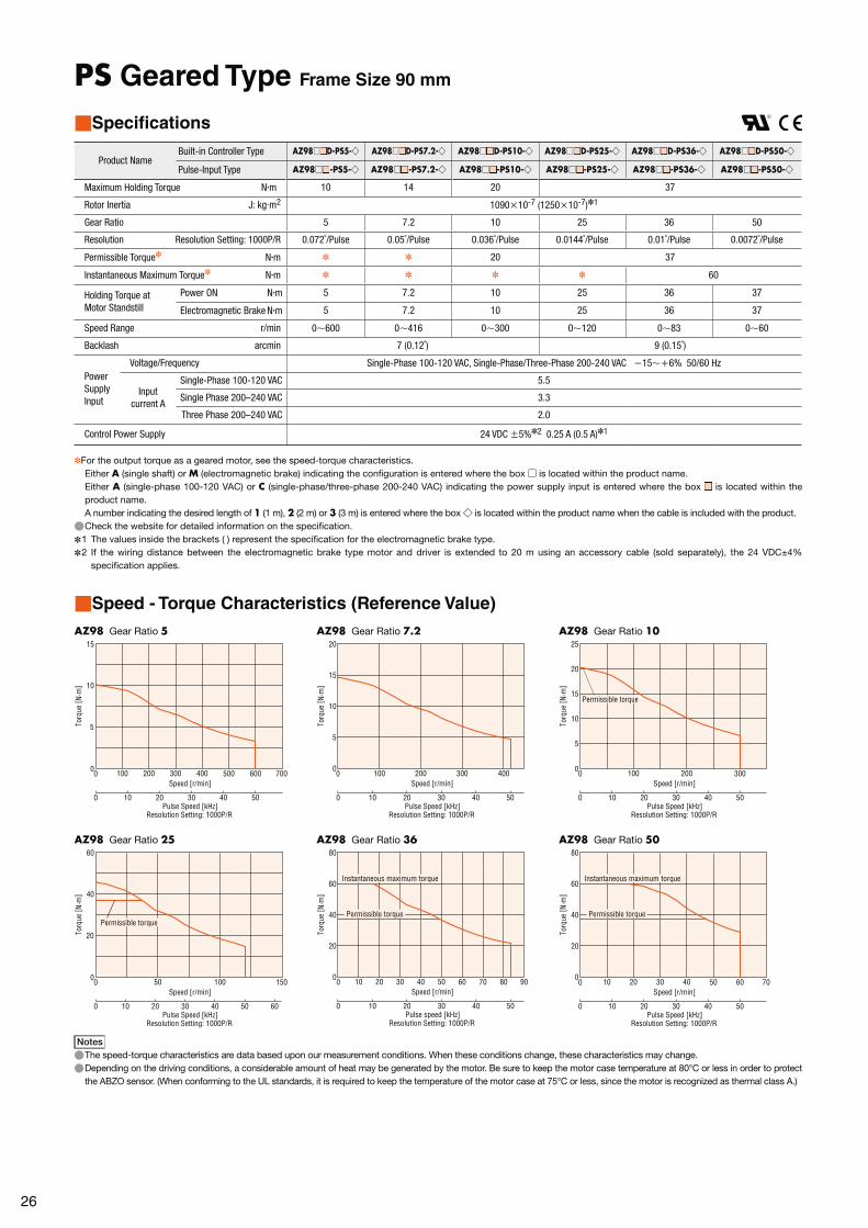
26
PS Geared Type Frame Size 90 mm
■Specifications
Product NameBuilt-in Controller Type AZ98 □ ■ D-PS5-◇ AZ98 □ ■ D-PS7.2-◇ AZ98 □ ■ D-PS10-◇ AZ98 □ ■ D-PS25-◇ AZ98 □ ■ D-PS36-◇ AZ98 □ ■ D-PS50-◇
Pulse-Input Type AZ98 □ ■ -PS5-◇ AZ98 □ ■ -PS7.2-◇ AZ98 □ ■ -PS10-◇ AZ98 □ ■ -PS25-◇ AZ98 □ ■ -PS36-◇ AZ98 □ ■ -PS50-◇
Maximum Holding Torque N·m 10 14 20 37
Rotor Inertia J: kg·m2 1090×10-7 (1250×10-7)✽1
Gear Ratio 5 7.2 10 25 36 50
Resolution Resolution Setting: 1000P/R 0.072˚/Pulse 0.05˚/Pulse 0.036˚/Pulse 0.0144˚/Pulse 0.01˚/Pulse 0.0072˚/Pulse
Permissible Torque✽ N·m ✽ ✽ 20 37
Instantaneous Maximum Torque✽ N·m ✽ ✽ ✽ ✽ 60
Holding Torque at Motor Standstill
Power ON N·m 5 7.2 10 25 36 37
Electromagnetic Brake N·m 5 7.2 10 25 36 37
Speed Range r/min 0∼600 0∼416 0∼300 0∼120 0∼83 0∼60
Backlash arcmin 7 (0.12˚) 9 (0.15˚)
Power Supply Input
Voltage/Frequency Single-Phase 100-120 VAC, Single-Phase/Three-Phase 200-240 VAC −15∼+6% 50/60 Hz
Input current A
Single-Phase 100-120 VAC 5.5
Single Phase 200–240 VAC 3.3
Three Phase 200–240 VAC 2.0
Control Power Supply 24 VDC ±5%✽2 0.25 A (0.5 A)✽1
✽For the output torque as a geared motor, see the speed-torque characteristics.Either A (single shaft) or M (electromagnetic brake) indicating the configuration is entered where the box □ is located within the product name. Either A (single-phase 100-120 VAC) or C (single-phase/three-phase 200-240 VAC) indicating the power supply input is entered where the box ■ is located within the product name. A number indicating the desired length of 1 (1 m), 2 (2 m) or 3 (3 m) is entered where the box ◇ is located within the product name when the cable is included with the product. ●Check the website for detailed information on the specification.
✽1 The values inside the brackets ( ) represent the specification for the electromagnetic brake type. ✽2 If the wiring distance between the electromagnetic brake type motor and driver is extended to 20 m using an accessory cable (sold separately), the 24 VDC±4%
specification applies.
■Speed - Torque Characteristics (Reference Value)
AZ98 Gear Ratio 5 AZ98 Gear Ratio 7.2 AZ98 Gear Ratio 10
0
15
10
5
0 200 300 400100 500 600 700
0 20 3010 40 50 Pulse Speed [kHz]
Resolution Setting: 1000P/R
Speed [r/min]
Torq
ue [ N
∙m]
0
20
15
10
5
0 200 300 400100
0 3020 4010 50 Pulse Speed [kHz]
Resolution Setting: 1000P/R
Torq
ue [ N
∙m]
Speed [r/min]
00 100 200 300
0 20 3010 40 50
25
20
15
10
5
Pulse Speed [kHz]Resolution Setting: 1000P/R
Torq
ue [ N
∙m]
Speed [r/min]
Permissible torque
AZ98 Gear Ratio 25 AZ98 Gear Ratio 36 AZ98 Gear Ratio 50
0 50 100 150
0 20 3010 40 50 60
0
60
40
20
Pulse Speed [kHz]Resolution Setting: 1000P/R
Speed [r/min]
Permissible torque
Torq
ue [ N
∙m]
0 40 5020 3010 60 70 80 90
0 20 3010 40 50
0
80
60
40
20
Pulse speed [kHz]Resolution Setting: 1000P/R
Speed [r/min]
Permissible torque
Instantaneous maximum torque
Torq
ue [ N
∙m]
0 20 30 4010 50 60 70
0 20 3010 40 50
0
80
60
40
20
Pulse Speed [kHz]Resolution Setting: 1000P/R
Speed [r/min]
Torq
ue [ N
∙m]
Permissible torque
Instantaneous maximum torque
Notes ●The speed-torque characteristics are data based upon our measurement conditions. When these conditions change, these characteristics may change. ●Depending on the driving conditions, a considerable amount of heat may be generated by the motor. Be sure to keep the motor case temperature at 80°C or less in order to protect the ABZO sensor. (When conforming to the UL standards, it is required to keep the temperature of the motor case at 75°C or less, since the motor is recognized as thermal class A.)
27
Features
System
C
onfig
uration
DC
Input
Pro
duct Line
Dim
ensions
Co
nnection
and O
peratio
nA
ccessories
AC
Input
System
C
onfig
uration
Pro
duct Line
Sp
ecifications
and F
eaturesD
imensio
nsC
onnectio
n and
Op
eration
Sp
ecifications
and F
eatures
AC
Input
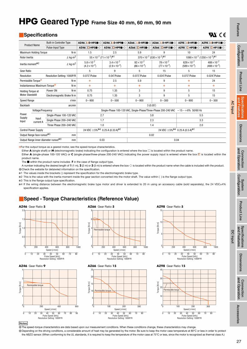
HPG Geared Type Frame Size 40 mm, 60 mm, 90 mm
■Specifications
Product NameBuilt-in Controller Type AZ46□ ■ D-HP5 ■-◇ AZ46□ ■ D-HP9 ■-◇ AZ66□ ■ D-HP5 ■-◇ AZ66□ ■ D-HP15 ■-◇ AZ98 □ ■ D-HP5 ■-◇ AZ98 □ ■ D-HP15 ■-◇
Pulse-Input Type AZ46□ ■ -HP5 ■-◇ AZ46□ ■ -HP9 ■-◇ AZ66□ ■ -HP5 ■-◇ AZ66□ ■ -HP15 ■-◇ AZ98 □ ■ -HP5 ■-◇ AZ98 □ ■ -HP15 ■-◇
Maximum Holding Torque N·m 1.5 2.5 5.9 9 10 24
Rotor Inertia J: kg·m2 55×10-7 (71×10-7)✽1 370×10-7 (530×10-7)✽1 1090×10-7 (1250×10-7)✽1
Inertia moment✽2 J: kg·m2 5.8×10⁻⁷
(4.2×10⁻⁷)3.4×10⁻⁷
(2.9×10⁻⁷)92×10-7
(86×10-7)78×10-7
(77×10-7)629×10-7
(589×10-7)488×10-7
(488×10-7)
Gear Ratio 5 9 5 15 5 15
Resolution Resolution Setting: 1000P/R 0.072˚/Pulse 0.04˚/Pulse 0.072˚/Pulse 0.024˚/Pulse 0.072˚/Pulse 0.024˚/Pulse
Permissible Torque✽ N·m ✽ 2.5 5.9 9 ✽ 24
Instantaneous Maximum Torque✽ N·m ✽ ✽ ✽ ✽ ✽ ✽
Holding Torque at Motor Standstill
Power ON N·m 0.75 1.35 3 9 5 15
Electromagnetic Brake N·m 0.75 1.35 3 9 5 15
Speed Range r/min 0∼900 0∼500 0∼900 0∼300 0∼900 0∼300
Backlash arcmin 3 (0.05˚)
Power Supply Input
Voltage/Frequency Single-Phase 100-120 VAC, Single-Phase/Three-Phase 200-240 VAC −15∼+6% 50/60 Hz
Input current A
Single-Phase 100-120 VAC 2.7 3.8 5.5
Single Phase 200–240 VAC 1.7 2.3 3.3
Three Phase 200–240 VAC 1.0 1.4 2.0
Control Power Supply 24 VDC ±5%✽4 0.25 A (0.33 A)✽1 24 VDC ±5%✽4 0.25 A (0.5 A)✽1
Output flange face runout✽3 mm 0.02
Output flange inner diameter runout✽3 mm 0.03 0.04
✽For the output torque as a geared motor, see the speed-torque characteristics.Either A (single shaft) or M (electromagnetic brake) indicating the configuration is entered where the box □ is located within the product name. Either A (single-phase 100-120 VAC) or C (single-phase/three-phase 200-240 VAC) indicating the power supply input is entered where the box ■ is located within the product name.The ■ within the product name includes F in the case of flange output type.A number indicating the desired length of 1 (1 m), 2 (2 m) or 3 (3 m) is entered where the box ◇ is located within the product name when the cable is included with the product. ●Check the website for detaiwled information on the specification.
✽1 The values inside the brackets ( ) represent the specification for the electromagnetic brake type. ✽2 This is the value with the inertia moment inside the gear section converted into the motor shaft. The value within ( ) is the flange output type. ✽3 This is the flange output type specification. ✽4 If the wiring distance between the electromagnetic brake type motor and driver is extended to 20 m using an accessory cable (sold separately), the 24 VDC±4%
specification applies.
■Speed - Torque Characteristics (Reference Value)
AZ46 Gear Ratio 5 AZ66 Gear Ratio 5 AZ98 Gear Ratio 5
0 200 400 600 800 1000
0 20 30 40 5010 60 80
0
2.0
1.0
1.5
0.5
70 Pulse Speed [kHz]
Resolution Setting: 1000P/R
Speed [r/min]
Torq
ue [ N
∙m]
0 200 400 600 800 1000
0 20 30 40 5010 60 80
0
8
4
6
2
70 Pulse Speed [kHz]
Resolution Setting: 1000P/R
Speed [r/min]
Torq
ue [ N
∙m]
Permissible torque
0 200 400 600 800 1000
0 20 30 40 5010 60 8070
0
15
10
5
Pulse Speed [kHz]Resolution Setting: 1000P/R
Speed [r/min]
Torq
ue [ N
∙m]
AZ46 Gear Ratio 9 AZ66 Gear Ratio 15 AZ98 Gear Ratio 15
0 200 400 600
0 20 30 40 5010 60 80 90
0
4
3
1
2
70 Pulse Speed [kHz]
Resolution Setting: 1000P/R
Speed [r/min]
Torq
ue [ N
∙m]
Permissible torque
0 100 200 300
0 20 30 40 5010 60 80
0
25
20
10
15
5
70 Pulse Speed [kHz]
Resolution Setting: 1000P/R
Speed [r/min]
Torq
ue [ N
∙m]
Permissible torque
0 100 200 300
0 20 30 40 5010 60 8070
0
40
30
20
10
Pulse Speed [kHz]Resolution Setting: 1000P/R
Speed [r/min]
Permissible torque
Torq
ue [ N
∙m]
Notes ●The speed-torque characteristics are data based upon our measurement conditions. When these conditions change, these characteristics may change. ●Depending on the driving conditions, a considerable amount of heat may be generated by the motor. Be sure to keep the motor case temperature at 80°C or less in order to protect the ABZO sensor. (When conforming to the UL standards, it is required to keep the temperature of the motor case at 75°C or less, since the motor is recognized as thermal class A.)

28
Harmonic Geared Type Frame Size 42 mm, 60 mm, 90 mm
■Specifications
Product NameBuilt-in Controller Type AZ46 □ ■ D-HS50-◇ AZ46 □ ■ D-HS100-◇ AZ66 □ ■ D-HS50-◇ AZ66 □ ■ D-HS100-◇ AZ98 □ ■ D-HS50-◇ AZ98 □ ■ D-HS100-◇
Pulse-Input Type AZ46 □ ■ -HS50-◇ AZ46 □ ■ -HS100-◇ AZ66 □ ■ -HS50-◇ AZ66 □ ■ -HS100-◇ AZ98 □ ■ -HS50-◇ AZ98 □ ■ -HS100-◇
Maximum Holding Torque N·m 3.5 5 7 10 33 52
Rotor Inertia J: kg·m2 72×10-7 (88×10-7)✽1 405×10-7 (565×10-7)✽1 1290×10-7 (1450×10-7)✽1
Gear Ratio 50 100 50 100 50 100
Resolution Resolution Setting:1000P/R 0.0072˚/Pulse 0.0036˚/Pulse 0.0072˚/Pulse 0.0036˚/Pulse 0.0072˚/Pulse 0.0036˚/Pulse
Permissible Torque N·m 3.5 5 7 10 33 52
Instantaneous Maximum Torque✽ N·m 8.3 11 23 36 ✽ 107
Holding Torque at Motor Standstill
Power ON N·m 3.5 5 7 10 33 52
Electromagnetic Brake N·m 3.5 5 7 10 33 52
Speed Range r/min 0∼70 0∼35 0∼70 0∼35 0∼70 0∼35
Lost Motion (Load torque)
arcmin1.5 or less
(±0.16N·m) 1.5 or less
(±0.20N·m) 0.7 or less
(±0.28N·m) 0.7 or less
(±0.39N·m) 0.7 or less (±1.2N·m)
Power Supply Input
Voltage/Frequency Single-Phase 100-120 VAC, Single-Phase/Three-Phase 200-240 VAC −15∼+6% 50/60 Hz
Input current A
Single-Phase 100-120 VAC 2.7 3.8 5.5
Single Phase 200–240 VAC 1.7 2.3 3.3
Three Phase 200–240 VAC 1.0 1.4 2.0
Control Power Supply 24 VDC ±5%✽2 0.25 A (0.33 A)✽1 24 VDC ±5%✽2 0.25 A (0.5 A)✽1
✽For the output torque as a geared motor, see the speed-torque characteristics.Either A (single shaft) or M (electromagnetic brake) indicating the configuration is entered where the box □ is located within the product name. Either A (single-phase 100-120 VAC) or C (single-phase/three-phase 200-240 VAC) indicating the power supply input is entered where the box ■ is located within the product name. A number indicating the desired length of 1 (1 m), 2 (2 m) or 3 (3 m) is entered where the box ◇ is located within the product name when the cable is included with the product. ●Check the website for detailed information on the specification.
✽1 The values inside the brackets ( ) represent the specification for the electromagnetic brake type. ✽2 If the wiring distance between the electromagnetic brake type motor and driver is extended to 20 m using an accessory cable (sold separately), the 24 VDC±4%
specification applies.Notes
●The rotor inertia represents a sum of the moments of inertia of the harmonic gear converted to motor shaft values.
■Speed - Torque Characteristics (Reference Value)
AZ46 Gear Ratio 50 AZ66 Gear Ratio 50 AZ98 Gear Ratio 50
0 20 40 60 80
0 20 3010 40 50 60
0
12
6
8
10
4
2
Pulse Speed [kHz]Resolution Setting: 1000P/R
Speed [r/min]
Torq
ue [ N
∙m]
Permissible torque
Instantaneous maximum torque
0 20 40 60 80
0 20 3010 40 50 60
0
30
15
20
25
10
5
Pulse Speed [kHz]Resolution Setting: 1000P/R
Speed [r/min]
Torq
ue [ N
∙m]
Permissible torque
Instantaneous maximum torque
0 20 40 60 80
0 20 3010 40 50 60
0
80
60
40
20
Pulse Speed [kHz]Resolution Setting: 1000P/R
Speed [r/min]
Permissible torque
Torq
ue [ N
∙m]
AZ46 Gear Ratio 100 AZ66 Gear Ratio 100 AZ98 Gear Ratio 100
0 10 20 30 40
0 20 3010 40 50 60
0
15
10
5
Pulse Speed [kHz]Resolution Setting: 1000P/R
Speed [r/min]
Torq
ue [ N
∙m]
Permissible torque
Instantaneous maximum torque
0 10 20 30 40
0 20 3010 40 50 60
0
50
40
20
30
10
Pulse Speed [kHz]Resolution Setting: 1000P/R
Speed [r/min]
Torq
ue [ N
∙m]
Permissible torque
Instantaneous maximum torque
0 10 20 30 40
0 20 3010 40 50 60
0
150
120
90
60
30
Pulse Speed [kHz]Resolution Setting: 1000P/R
Speed [r/min]
Permissible torque
Instantaneous maximum torque
Torq
ue [ N
∙m]
Notes ●The speed-torque characteristics are data based upon our measurement conditions. When these conditions change, these characteristics may change. ●Depending on the driving conditions, a considerable amount of heat may be generated by the motor. Be sure to keep the motor case temperature at 80°C or less in order to protect the ABZO sensor. (When conforming to the UL standards, it is required to keep the temperature of the motor case at 75°C or less, since the motor is recognized as thermal class A.)

29
Features
System
C
onfig
uration
DC
Input
Pro
duct Line
Dim
ensions
Co
nnection
and O
peratio
nA
ccessories
AC
Input
System
C
onfig
uration
Pro
duct Line
Sp
ecifications
and F
eaturesD
imensio
nsC
onnectio
n and
Op
eration
Sp
ecifications
and F
eatures
AC
Input
■Driver Specifications
Built-in Controller Type Pulse-Input Type
I/O Functions
Pulse-Input Type −
Maximum input pulse Frequency Host controller has line driver output: 1 MHz (when Duty 50%) Host controller has open collector output: 250 kHz (when Duty 50%) Negative logic pulse input (initial values)
Direct Input Number of Input: 10 Number of Input: 6
Direct Output Number of Output: 6
RS-485 Com-munications
Network Input 16 Bit −
Network Output 16 Bit −
Number of Positioning Data Sets 256 256 (up to 32 available)
Data Setting Software MEXE02 ◯
■Built-in Controller Type RS-485 Communication Specification
Protocol Modbus RTU mode
Electrical CharacteristicsEIA-485 standard, straight cableUsing shielded twisted pair cables (recommended TIA/EIA-568B CAT5e or more), a total maximum length of 50 m can be used.
Communication Mode Half-duplex communications, start-stop synchronization (data: 8-bit, stop bit(s): 1 bit/2 bits, parity: none/even/odd)
Baud Rate Selection from 9600 bps/19200 bps/38400 bps/57600 bps/115200 bps/230400 bps
Connection Type A maximum of 31 units could be connected for each programmable controller (master device).
■General Specifications
MotorDriver
Built-in Controller Type Pulse-Input Type
Thermal Class130 (B)
[UL is certified as 105 (A)]−
Insulation Resistance
The measured value is 100 MΩ or more when a 500 VDC megger is applied between the following locations:
· Case - Motor Windings · Case - Electromagnetic Brake Windings✽1
The measured value is 100 MΩ or more when a 500 VDC megger isapplied between the following locations:
· Protective Earth Terminal - Power Supply Terminal · Encoder Connector - Power Supply Terminal · Power Input Terminal - Power Supply Terminal
Dielectric Strength
No abnormality is found with the following application for 1 minute:
· Case - Motor Windings 1.5 kVAC, 50 Hz or 60 Hz · Case - Electromagnetic Brake Windings✽1 1.5 kVAC, 50 Hz or 60 Hz
No abnormality is found with the following application for 1 minute: · Protective Earth Terminal - Power Supply Terminal 1.5 kVAC, 50 Hz or 60 Hz
· Encoder Connector - Power Supply Terminal 1.8 kVAC, 50 Hz or 60 Hz · I/O Signal Terminal - Power Supply Terminal 1.8 kVAC, 50 Hz or 60 Hz
Operating Environment (in operation)
Ambient Tempera-ture
0∼+40˚C (non-freezing) 0∼+55˚C (non-freezing)✽2
Ambient Humidity
85% or less (no condensation)
Atmos-phere
No corrosive gases or dirt. Not directly affected by water or oil.
Degree of Protection IP66 (excluding mounting surface and connector) IP10 IP20
Stop Position Accuracy AZ46: ±4 min (±0.067°) AZ66, AZ69, AZ98, AZ911: ±3 min (±0.05°)
Shaft Runout 0.05 T.I.R. (mm)✽3 −
Concentricity 0.075 T.I.R. (mm)✽3 −
Perpendicularity 0.075 T.I.R. (mm)✽3 −
Multi-rotation detection range in power off state
±900 rotations (1,800 rotations)
✽1 Electromagnetic brake type only ✽2 When attaching a heat sink equivalent to or more than an aluminum plate of 200×200 mm with thickness of 2 mm ✽3 T.I.R. (Total Indicator Reading): Centered around the reference shaft, this expresses the total volume read from the dial gauge
when the measured section is rotated once.Notes
●When connecting the motor and the driver, do not measure insulation resistance or perform pressure resistance tests.Furthermore, do not perform these tests on the motor ABZO sensor.
A
A0.075
Aϕ0.075
0.05
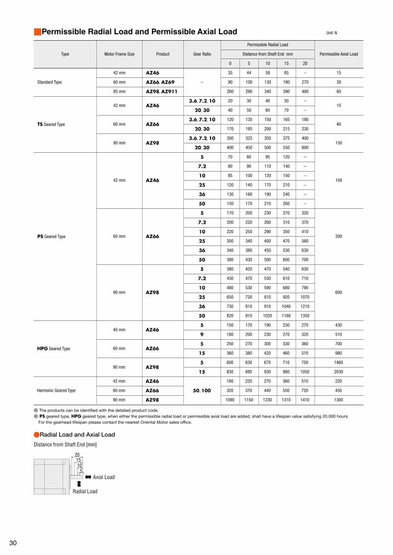
30
■Permissible Radial Load and Permissible Axial Load Unit: N
Type Motor Frame Size Product Gear Ratio
Permissible Radial Load
Permissible Axial LoadDistance from Shaft End mm
0 5 10 15 20
Standard Type
42 mm AZ46
−
35 44 58 85 − 15
60 mm AZ66, AZ69 90 100 130 180 270 30
85 mm AZ98, AZ911 260 290 340 390 480 60
TS Geared Type
42 mm AZ463.6, 7.2, 10 20 30 40 50 −
1520, 30 40 50 60 70 −
60 mm AZ663.6, 7.2, 10 120 135 150 165 180
4020, 30 170 185 200 215 230
90 mm AZ983.6, 7.2, 10 300 325 350 375 400
15020, 30 400 450 500 550 600
PS Geared Type
42 mm AZ46
5 70 80 95 120 −
100
7.2 80 90 110 140 −
10 85 100 120 150 −
25 120 140 170 210 −
36 130 160 190 240 −
50 150 170 210 260 −
60 mm AZ66
5 170 200 230 270 320
200
7.2 200 220 260 310 370
10 220 250 290 350 410
25 300 340 400 470 560
36 340 380 450 530 630
50 380 430 500 600 700
90 mm AZ98
5 380 420 470 540 630
600
7.2 430 470 530 610 710
10 480 530 590 680 790
25 650 720 810 920 1070
36 730 810 910 1040 1210
50 820 910 1020 1160 1350
HPG Geared Type
40 mm AZ465 150 170 190 230 270 430
9 180 200 230 270 320 510
60 mm AZ665 250 270 300 330 360 700
15 360 380 420 460 510 980
90 mm AZ985 600 630 670 710 750 1460
15 830 880 930 980 1050 2030
Harmonic Geared Type
42 mm AZ46
50, 100
180 220 270 360 510 220
60 mm AZ66 320 370 440 550 720 450
90 mm AZ98 1090 1150 1230 1310 1410 1300
● The products can be identified with the detailed product code.● PS geared type, HPG geared type, when either the permissible radial load or permissible axial load are added, shall have a lifespan value satisfying 20,000 hours.
For the gearhead lifespan please contact the nearest Oriental Motor sales office.
●Radial Load and Axial Load
15
510
20
Distance from Shaft End [mm]
Axial Load
Radial Load

31
Features
System
C
onfig
uration
DC
Input
Pro
duct Line
Dim
ensions
Co
nnection
and O
peratio
nA
ccessories
AC
Input
System
C
onfig
uration
Pro
duct Line
Sp
ecifications
and F
eaturesD
imensio
nsC
onnectio
n and
Op
eration
Sp
ecifications
and F
eatures
AC
Input
■Permissible Moment Load
If an excentric load is applied when attaching an arm or table to the flange face, calculate the moment load with the following formula. The moment load should not exceed the permissible values shown in the table below.
●HPG Geared Type Flange Output Type
Product Name Gear Ratio Permissible Moment Load (N·m)
AZ465 4.9
9 5.9
AZ665 12
15 17.2
AZ985 38.7
15 53.5
The required moment load can be calculated according to the following formula.
Example 1: When external force F is applied at a distance of L from the centre of the output flange
Required moment load [N·m]: M=F×L
L [m]F [N]
Example 2: When external force F1 is applied at a distance of L from the surface mounting of the output flange
Required moment load[N·m]: M=F1× (L+coefficient a)
L [m]
F1 [N]
Product Name Coefficient a (m)
AZ46 0.006
AZ66 0.011
AZ98 0.0115
●Harmonic Geared Type
Product Name Gear RatioPermissible Moment Load
(N·m)
AZ4650, 100
5.6
AZ66 11.6
The required moment load can be calculated according to the following formula.
Example 1: When external force F is applied at a distance of L from the centre of the output flange
Required moment load [N·m]: M=F×L
L [m]
F [N]

32
The following are the relationships between the load torque and driver input current at each speed when the motor is operated. From these characteristics, it is possible to estimate the current capacity actually required when used with multiple axes. For geared motors, convert to torque and speed at the motor shaft.
Motor shaft speed = Gear output shaft speed × Gear ratio [r/min]
Motor shaft torque = Gear output shaft torque
[N·m]Gear Ratio
●Single-Phase 100-120 VACAZ46□A
●Single Phase 200–240 VACAZ46□C
●Three Phase 200–240 VACAZ46□C
3000r/min4000r/min
2000r/min
1000r/min
500r/min
3.0
2.5
2.0
1.5
1.0
0.5
00.1 0.2 0.3 0.40
Driv
er In
put C
urre
nt [ A
]
Load Torque [N·m]
3000r/min4000r/min
2000r/min
1000r/min
500r/min
2.0
1.5
1.0
0.5
0.1 0.2 0.3 0.400
Driv
er In
put C
urre
nt [ A
]
Load Torque [N·m]
3000r/min4000r/min
2000r/min
1000r/min
500r/min
1.0
0.75
0.5
0.25
0.1 0.2 0.3 0.400
Driv
er In
put C
urre
nt [ A
]
Load Torque [N·m]
AZ66□A AZ66□C AZ66□C
3000r/min4000r/min 2000r/min
1000r/min
500r/min
0.25 0.5 0.75 1.0 1.25 1.500
5
4
3
2
1Driv
er In
put C
urre
nt [ A
]
Load Torque [N·m]
3000r/min4000r/min 2000r/min
1000r/min
500r/min
3.0
2.5
2.0
1.5
1.0
0.5
00.25 0.5 0.75 1.0 1.25 1.50
Driv
er In
put C
urre
nt [ A
]
Load Torque [N·m]
3000r/min4000r/min 2000r/min
1000r/min
500r/min
0.25 0.5 0.75 1.0 1.25 1.50
1.5
1.25
1.0
0.75
0.5
0.25
0
Load Torque [N·m]Dr
iver
Inpu
t Cur
rent
[ A]
AZ69□A AZ69□C AZ69□C
3000r/min4000r/min2000r/min
1000r/min
500r/min
6
5
4
3
2
1
0.5 1.0 1.5 2.000
Driv
er In
put C
urre
nt [ A
]
Load Torque [N·m]
3000r/min4000r/min2000r/min
1000r/min
500r/min
3.5
2.5
3.0
2.0
1.5
1.0
0.5
00.5 1.0 2.01.50
Driv
er In
put C
urre
nt [ A
]
Load Torque [N·m]
3000r/min4000r/min
2000r/min
1000r/min
500r/min
2.0
1.5
1.0
0.5
00.5 1.0 2.01.50
Load Torque [N·m]
Driv
er In
put C
urre
nt [ A
]
AZ98□A AZ98□C AZ98□C
3000r/min4000r/min 2000r/min
1000r/min
500r/min
6
5
4
3
2
1
0.5 1.0 1.5 2.52.000
Driv
er In
put C
urre
nt [ A
]
Load Torque [N·m]
3000r/min4000r/min 2000r/min
1000r/min
500r/min
3.5
2.5
3.0
2.0
1.5
1.0
0.5
00.5 1.0 1.5 2.52.00
Load Torque [N·m]
Driv
er In
put C
urre
nt [ A
] 3000r/min4000r/min 2000r/min
1000r/min
500r/min
0.5 1.0 1.5 2.52.00
2.0
1.5
1.0
0.5
00
Load Torque [N·m]
Driv
er In
put C
urre
nt [ A
]
AZ911□A AZ911□C AZ911□C
3000r/min4000r/min 2000r/min 1000r/min
500r/min
7
5
6
4
3
2
1
1 2 4300
Driv
er In
put C
urre
nt [ A
]
Load Torque [N·m]
4
3
2
1
1 2 4300
3000r/min4000r/min 2000r/min1000r/min
500r/min
Driv
er In
put C
urre
nt [ A
]
Load Torque [N·m]
4000r/min 2000r/min 1000r/min
500r/min
2.5
2.0
1.5
1.0
0.5
1 2 4300
3000r/min
Driv
er In
put C
urre
nt [ A
]
Load Torque [N·m]
■Load Torque - Driver Input Current Characteristics

33
Features
System
C
onfig
uration
DC
Input
Pro
duct Line
Co
nnection
and O
peratio
nA
ccessories
AC
Input
System
C
onfig
uration
Pro
duct Line
Sp
ecifications
and F
eaturesD
imensio
nsC
onnectio
n and
Op
eration
Dim
ensions
AC
Input
Sp
ecifications
and features
■Dimensions (Unit = mm)
●Motors ◇Standard Type
Frame Size 42 mm
Product NameMotor Product Name
MasskgBuilt-in Controller Pulse-Input
AZ46A ■D-◇ AZ46A ■-◇ AZM46AC 0.44
275
4213
42
ϕ22
−0.
021 (
h7)
0ϕ
6−0.
012 (
h7)
05.5±
0.15
15±0.25
220±1
31±0.2
31±
0.2
70
28.5
300
12
300
5557-06R-210 (Molex)55100-0670 (Molex)
4×M3×4.5 Deep
Motor Cable ϕ8
Encoder Cable ϕ6Protective Earth Terminal M4
Frame Size 60 mm
Product NameMotor Product Name L
MasskgBuilt-in Controller Pulse-Input
AZ66A ■D-◇ AZ66A ■-◇ AZM66AC 72 0.91
AZ69A ■D-◇ AZ69A ■-◇ AZM69AC 97.5 1.4
50±0.35
60
50±
0.35
6013
275
ϕ10
−0.
015 (
h7)
09.5±
0.15
ϕ36
−0.
025 (
h7)
0
20±0.25
24±1
27L
28.512
300
300
55100-0670 (Molex) 5557-06R-210 (Molex)
Motor Cable ϕ8Encoder Cable ϕ6
4×ϕ4.5 Thru
Protective Earth Terminal M4
Frame Size 85 mm
Product NameMotor Product Name L
MasskgBuilt-in Controller Pulse-Input
AZ98A ■ D-◇ AZ98A ■-◇ AZM98AC 84 1.9
AZ911A ■ D-◇ AZ911A ■-◇ AZM911AC 114 3
5 27
85
8513
70±0.35
70±
0.35
25±0.25
37±1
210L
13±
0.15
ϕ14
−0.
018 (
h7)
0
ϕ60
−0.
030 (
h7)
0
28.512
300
300
55100-0670 (Molex) 5557-06R-210 (Molex)
4×ϕ6.5 Thru
Motor Cable ϕ8
Encoder Cable ϕ6Protective Earth Terminal M4
●Either A (single-phase 100-120 VAC) or C (single-phase/three-phase 200-240 VAC) indicating the power supply input is entered where the box ■ is located within the product name.A number indicating the desired length of 1 (1 m), 2 (2 m) or 3 (3 m) is entered where the box ◇ is located within the product name when the cable is included with the product.

34
◇Standard Type with Electromagnetic BrakeFrame Size 42 mm
Product NameMotor Product Name
MasskgBuilt-in Controller Pulse-Input
AZ46M ■D-◇ AZ46M ■-◇ AZM46MC 0.61
ϕ22
−0.
021 (
h7)
ϕ6 −
0.01
2 (h7
)5.
5 ±0.
15
15±0.25
220±1101
5557-06R-210 (Molex)55100-0670 (Molex)5557-02R-210 (Molex)
300
300
300
275
4213
4231±0.2
31±
0.2
0028.512121526
Motor Cable ϕ8
Electromagnetic Brake Cable ϕ6
Encoder Cable ϕ6
4×M3×4.5 Deep
Protective Earth Terminal M4
Frame Size 60 mm
Product NameMotor Product Name L
MasskgBuilt-in Controller Pulse-Input
AZ66M ■ D-◇ AZ66M ■ -◇ AZM66MC 118 1.3
AZ69M ■ D-◇ AZ69M ■ -◇ AZM69MC 143.5 1.8
50±0.35
60
50±
0.35
6013
20±0.25
24±1
27L
ϕ10
−0.
015 (
h7)
09.5±
0.15
ϕ36
−0.
025 (
h7)
028.512
300
300
300
12
5557-06R-210 (Molex)5557-02R-210 (Molex)
55100-0670 (Molex)
15.526
275
Motor Cable ϕ8
Electromagnetic Brake Cable ϕ6
Encoder Cable ϕ6
4×ϕ4.5 Thru
Protective Earth Terminal M4
Frame Size 85 mm
Product NameMotor Product Name
MasskgBuilt-in Controller Pulse-Input
AZ98M ■ D-◇ AZ98M ■-◇ AZM98MC 2.5
5 27
85
8513
70±0.35
70±
0.35
13±
0.15
ϕ14
−0.
018 (
h7)
0
ϕ60
−0.
030 (
h7)
0
25±0.25
37±1
210125.5
28.5
300
300
300
1212
5557-02R-210 (Molex)5557-06R-210 (Molex)55100-0670 (Molex)
Protective Earth Terminal M4
4×ϕ6.5 Thru
Motor Cable ϕ8
Electromagnetic Brake Cable ϕ6
Encoder Cable ϕ6
●The ■ within the product name includes A (single phase 100–120 V) or C (single phase/three phase 200–240 V) expressing power input.A number indicating the desired length of 1 (1 m), 2 (2 m) or 3 (3 m) is entered where the box ◇ is located within the product name when the cable is included with the product.

35
Features
System
C
onfig
uration
DC
Input
Pro
duct Line
Sp
ecifications
and F
eaturesC
onnectio
n and
Op
eration
Accesso
ries
AC
Input
System
C
onfig
uration
Pro
duct Line
Sp
ecifications
and F
eaturesD
imensio
nsC
onnectio
n and
Op
eration
Dim
ensions
AC
Input
◇TS Geared TypeFrame Size 42 mm
Product NameMotor Product Name Gear Ratio
MasskgBuilt-in Controller Pulse-Input
AZ46A ■ D-TS ■ -◇ AZ46A ■ -TS ■ -◇ AZM46AC-TS ■ 3.6, 7.2, 10, 20, 30 0.59
42
4213ϕ43.8±0.5
5.5±
0.15
8±0.
5
ϕ6−
0.01
2 (h7
)0
ϕ17
−0.
018 (
h7)
0
28.5
300
12
300
5557-06R-210 (Molex)55100-0670 (Molex)
101 20±1
3.512
275
4×M4×8 Deep
Encoder Cable ϕ6
Motor Cable ϕ8
Protective Earth Terminal M4
Frame Size 60 mm
Product NameMotor Product Name Gear Ratio
MasskgBuilt-in Controller Pulse-Input
AZ66A ■ D-TS ■ -◇ AZ66A ■ -TS ■ -◇ AZM66AC-TS ■ 3.6, 7.2, 10, 20, 30 1.3
● Installation screw: M4×60 P0.7 (4 screws included)
ϕ70±0.56060
13
ϕ23
−0.
021 (
h7)
010
±0.
5
ϕ10
−0.
015 (
h7)
0
11550
32±1
184
28.512
300
300
5557-06R-210 (Molex)55100-0670 (Molex)
A
A
A-A
11.2
18±0.2
3−0.
029
−0.
004
1.8+0.1 03−0.025
0
03−
0.02
5
275
4×ϕ4.5 Thru
Motor Cable ϕ8Encoder Cable ϕ6
Parallel Key (Included)
Protective Earth Terminal M4
Frame Size 90 mm
Product NameMotor Product Name Gear Ratio
MasskgBuilt-in Controller Pulse-Input
AZ98A ■ D-TS ■ -◇ AZ98A ■ -TS ■ -◇ AZM98AC-TS ■ 3.6, 7.2, 10, 20, 30 3.1
● Installation screw: M8×90 P1.25 (4 screws included)
300
300
90
ϕ104±0.5
90
5 27
57434±0.5
25
A
A
ϕ39
−0.
025 (
h7)
18±
0.5
ϕ18
−0.
018 (
h7)
0 0
12
13
5557-06R-210 (Molex)55100-0670 (Molex)
20.5
A-A
42±1148
28.5 Protective Earth Terminal M4
Encoder Cable ϕ6
25±0.2 6−0.030
3.5+0.1 0
6−0.
030
6−0.
030
Parallel Key (Included)
4×ϕ8.5 ThruM6×12 Deep
Motor Cable ϕ8
●Either A (single-phase 100-120 VAC) or C (single-phase/three-phase 200-240 VAC) indicating the power supply input is entered where the box ■ is located within the product name.The ■ within the product name includes a number expressing the gear ratio.A number indicating the desired length of 1 (1 m), 2 (2 m) or 3 (3 m) is entered where the box ◇ is located within the product name when the cable is included with the product.

36
●Either A (single-phase 100-120 VAC) or C (single-phase/three-phase 200-240 VAC) indicating the power supply input is entered where the box ■ is located within the product name.The ■ within the product name includes a number expressing the gear ratio.A number indicating the desired length of 1 (1 m), 2 (2 m) or 3 (3 m) is entered where the box ◇ is located within the product name when the cable is included with the product.
◇TS Geared Type with Electromagnetic BrakeFrame Size 42 mm
Product NameMotor Product Name Gear Ratio
MasskgBuilt-in Controller Pulse-Input
AZ46M ■ D-TS ■ -◇ AZ46M ■ -TS ■ -◇ AZM46MC-TS ■ 3.6, 7.2, 10, 20, 30 0.76
42
4213ϕ43.8±0.5
2751526 5.
5±0.
15
8±0.
5
ϕ6−
0.01
2 (h7
)0
ϕ17
−0.
018 (
h7)
0
132 20±1
3.512
5557-06R-210 (Molex)55100-0670 (Molex)5557-02R-210 (Molex)
300
300
300
28.51212
4×M4×8 Deep
Protective Earth Terminal M4
Motor Cable ϕ8
Electromagnetic Brake Cable ϕ6
Encoder Cable ϕ6
Frame Size 60 mm
Product NameMotor Product Name Gear Ratio
MasskgBuilt-in Controller Pulse-Input
AZ66M ■ D-TS ■ -◇ AZ66M ■ -TS ■ -◇ AZM66MC-TS ■ 3.6, 7.2, 10, 20, 30 1.7
● Installation screw: M4×60 P0.7 (4 screws included)
18
12 12 28.5
300
300
300
450161
2615.5
A
A
5557-06R-210 (Molex)5557-02R-210 (Molex)
55100-0670 (Molex)
ϕ23
−0.
021 (
h7)
010
±0.
5
ϕ10
−0.
015 (
h7)
0
32±1
11.2
A-A
Motor Cable ϕ8
18±0.2
3−0.
029
−0.
004
1.8+0.1 03−0.025
0
03 −
0.02
5
Parallel Key (Included)
60
6013
ϕ70±0.5
275Protective Earth Terminal M4
4×ϕ4.5 Thru
Electromagnetic Brake Cable ϕ6
Encoder Cable ϕ6
Frame Size 90 mm
Product NameMotor Product Name Gear Ratio
MasskgBuilt-in Controller Pulse-Input
AZ98M ■ D-TS ■ -◇ AZ98M ■ -TS ■ -◇ AZM98MC-TS ■ 3.6, 7.2, 10, 20, 30 3.7
● Installation screw: M8×90 P1.25 (4 screws included)
90
ϕ104±0.5
90
5 2728.51212
300
5557-02R-210 (Molex)5557-06R-210 (Molex)55100-0670 (Molex)
57434±0.5
25
A
A
ϕ39
−0.
025 (
h7)
18±
0.5
ϕ18
−0.
018 (
h7)
0 0
42±1189.5
300 20.5
A-A
25±0.2 6−0.030
3.5+0.1 0
6−0.
030
6−0.
030
300
13
Electromagnetic Brake Cable ϕ6 Parallel Key (Included)
Protective Earth Terminal M4
4×ϕ8.5 ThruM6×12 Deep
Motor Cable ϕ8
Encoder Cable ϕ6

37
Features
System
C
onfig
uration
DC
Input
Pro
duct Line
Sp
ecifications
and F
eaturesC
onnectio
n and
Op
eration
Accesso
ries
AC
Input
System
C
onfig
uration
Pro
duct Line
Sp
ecifications
and F
eaturesD
imensio
nsC
onnectio
n and
Op
eration
Dim
ensions
AC
Input
◇PS Geared TypeFrame Size 42 mm
Product NameMotor Product Name Gear Ratio L
MasskgBuilt-in Controller Pulse-Input
AZ46A ■ D-PS ■ -◇ AZ46A ■ -PS ■ -◇ AZM46AC-PS ■ 5, 7.2, 10 98 0.64
25, 36, 50 121.5 0.79
ϕ43.8±0.5
42
4213
L 28±1
10 15
A
A
ϕ10
−0.
015 (
h7)
ϕ26
−0.
021 (
h7)
00
11.2
A-A
28.5
300
12
300
5557-06R-210 (Molex)55100-0670 (Molex)
275
4×M4×8 Deep
15±0.2 3−0.0250
1.8+0.1 0
03−
0.02
5
3−0.
029
−0.
004
Parallel Key (Included)
Encoder Cable ϕ6
Motor Cable ϕ8
Protective Earth Terminal M4
Frame Size 60 mm
Product NameMotor Product Name Gear Ratio L
MasskgBuilt-in Controller Pulse-Input
AZ66A ■ D-PS ■ -◇ AZ66A ■ -PS ■ -◇ AZM66AC-PS ■ 5, 7.2, 10 104 1.3
25, 36, 50 124 1.6
ϕ70±0.560
6013
28.512
5557-06R-210 (Molex)55100-0670 (Molex)
300
300
L 38±1
2510
0ϕ
12−
0.01
8 (h7
)
ϕ37
−0.
025 (
h7)
0
25±0.2 4−0.030
04−
0.03
04−
0.03
2.5 0+0.1
A-A
13.5
A
A
275
4×M5×10 Deep
Motor Cable ϕ8Encoder Cable ϕ6
Parallel Key (Included)
Protective Earth Terminal M4
Frame Size 90 mm
Product NameMotor Product Name Gear Ratio L
MasskgBuilt-in Controller Pulse-Input
AZ98A ■ D-PS ■ -◇ AZ98A ■ -PS ■ -◇ AZM98AC-PS ■5, 7.2, 10 131 3.3
25, 36, 50 158.5 4.1
L
90
ϕ104±0.5
90
5 27
1425
47±1
26
A
A
300
300
20.5
12
13
5557-06R-210 (Molex)55100-0670 (Molex)
A-A
25±0.2 6−0.030
3.5+0.1 0
6−0.
030
6−0.
030
28.5
ϕ18
−0.
018 (
h7)
0
ϕ61
−0.
03 ( h
7)0
Protective Earth Terminal M4
4×M8×15 Deep
Encoder Cable ϕ6 Parallel Key (Included)
Motor Cable ϕ8
●Either A (single-phase 100-120 VAC) or C (single-phase/three-phase 200-240 VAC) indicating the power supply input is entered where the box ■ is located within the product name.The ■ within the product name includes a number expressing the gear ratio.A number indicating the desired length of 1 (1 m), 2 (2 m) or 3 (3 m) is entered where the box ◇ is located within the product name when the cable is included with the product.

38
◇PS Geared Type with Electromagnetic BrakeFrame Size 42 mm
Product NameMotor Product Name Gear Ratio L
MasskgBuilt-in Controller Pulse-Input
AZ46M ■ D-PS ■ -◇ AZ46M ■ -PS ■ -◇ AZM46MC-PS ■ 5, 7.2, 10 129 0.81
25, 36, 50 152 0.96
42
4213ϕ43.8±0.5
2751526
L 28±1
10 15
ϕ10
−0.
015 (
h7)
ϕ26
−0.
021 (
h7)
00
A
A
5557-06R-210 (Molex)55100-0670 (Molex)5557-02R-210 (Molex)
300
300
300
28.51212
11.2
15±0.2 3−0.0250
1.8+0.1 0
03−
0.02
5
A-A
3−0.
029
−0.
004
4×M4×8 Deep
Protective Earth Terminal M4Encoder Cable ϕ6
Motor Cable ϕ8
Electromagnetic Brake Cable ϕ6
Parallel Key (Included)
Frame Size 60 mm
Product NameMotor Product Name Gear Ratio L
MasskgBuilt-in Controller Pulse-Input
AZ66M ■ D-PS ■ -◇ AZ66M ■ -PS ■ -◇ AZM66MC-PS ■ 5, 7.2, 10 150 1.725, 36, 50 170 2.0
25
12 12 28.5
300
300
300
10L
2615.5
A
A
13.5
A-A
0ϕ
12−
0.01
8 (h7
)
5557-06R-210 (Molex)5557-02R-210 (Molex)
55100-0670 (Molex)
38±1
ϕ37
−0.
025 (
h7)
0
25±0.2 4−0.030
04−
0.03
04−
0.03
2.5 0+0.1
Parallel Key (Included)
27
60
6013
5
ϕ70±0.54×M5×10 Deep
Protective Earth Terminal M4
Motor Cable ϕ8
Electromagnetic Brake Cable ϕ6
Encoder Cable ϕ6
Frame Size 90 mm
Product NameMotor Product Name Gear Ratio L
MasskgBuilt-in Controller Pulse-Input
AZ98M ■ D-PS ■ -◇ AZ98M ■ -PS ■ -◇ AZM98MC-PS ■5, 7.2, 10 172.5 3.9
25, 36, 50 200 4.7
A
A
20.5
A-A
28.51212
300
5557-02R-210 (Molex)5557-06R-210 (Molex)55100-0670 (Molex)
300
300
13
ϕ18
−0.
018 (
h7)
0
ϕ61
−0.
03 ( h
7)0
L14
25
47±1
2690
ϕ104±0.5
90
5 27Protective Earth Terminal M4
4×M8×15 Deep
Motor Cable ϕ8
Electromagnetic Brake Cable ϕ6Encoder Cable ϕ6
25±0.2 6−0.030
3.5+0.1 0
6−0.
030
6−0.
030
Parallel Key (Included)
●Either A (single-phase 100-120 VAC) or C (single-phase/three-phase 200-240 VAC) indicating the power supply input is entered where the box ■ is located within the product name.The ■ within the product name includes a number expressing the gear ratio.A number indicating the desired length of 1 (1 m), 2 (2 m) or 3 (3 m) is entered where the box ◇ is located within the product name when the cable is included with the product.

39
Features
System
C
onfig
uration
DC
Input
Pro
duct Line
Sp
ecifications
and F
eaturesC
onnectio
n and
Op
eration
Accesso
ries
AC
Input
System
C
onfig
uration
Pro
duct Line
Sp
ecifications
and F
eaturesD
imensio
nsC
onnectio
n and
Op
eration
Dim
ensions
AC
Input
◇HPG Geared Type Shaft Output TypeFrame Size 40 mm
Product NameMotor Product Name Gear Ratio
MasskgBuilt-in Controller Pulse-Input
AZ46A ■ D-HP ■ -◇ AZ46A ■ -HP■ -◇ AZM46AC-HP ■ 5, 9 0.71
40
40
ϕ46±0.3
28.5
300
12
300
5557-06R-210 (Molex)55100-0670 (Molex)
42
104.5 42±1
5 2215
4213
2.2 15A
A
0ϕ
10−
0.01
5 (h7
)
ϕ40
−0.
025 (
h7)
0ϕ
39.5
ϕ29
2.5+0.1 0
4−0.
030
0
4−0.0300
4−0.
030
0
15−0.180
1.6
90˚
11.5
A-A
275
M3×6 Deep4×ϕ3.4 Thru
Encoder Cable ϕ6
Motor Cable ϕ8
Parallel Key (Included)
Protective Earth Terminal M4
Frame Size 60 mm
Product NameMotor Product Name Gear Ratio
MasskgBuilt-in Controller Pulse-Input
AZ66A ■ D-HP ■ -◇ AZ66A ■ -HP ■ -◇ AZM66AC-HP ■ 5, 15 1.9
ϕ70±0.36060
13
132 58±1
8 30212.5 25
0ϕ
16−
0.01
8 (h7
)
12
300
300
5557-06R-210 (Molex)55100-0670 (Molex)
A
A
ϕ40
ϕ20
ϕ55
.5ϕ
56−
0.03
0 (h7
)0
A-A
18
25−0.210
2 90˚
5−0.0300
5−0.
030
0
3+0.1 0
5−0.
030
0
27528.5
4×ϕ5.5 Thru
M4×8 Deep
Encoder Cable ϕ6Motor Cable ϕ8
Parallel Key (Included)
Protective Earth Terminal M4
Frame Size 90 mm
Product NameMotor Product Name Gear Ratio
MasskgBuilt-in Controller Pulse-Input
AZ98A ■ D-HP ■-◇ AZ98A ■ -HP ■-◇ AZM98AC-HP ■ 5, 15 4.8
36
ϕ25
−0.
021 (
h7)
0
ϕ32
ϕ59
ϕ84
ϕ85
−0.
035 (
h7)
0
8
10 3880±1160
27
5 27
90
90
ϕ105±0.3
28
3.2
36−0.250
7−0.0900
8−0.
036
0
8−0.
036
0
4 0+0.2
A
A
A-A
300
300
12
13
5557-06R-210 (Molex)55100-0670 (Molex)
28.5
90˚
Protective Earth Terminal M4
Parallel Key (Included)
M6×12 Deep
Encoder Cable ϕ6
Motor Cable ϕ8
4×ϕ9 Thru
●Either A (single-phase 100-120 VAC) or C (single-phase/three-phase 200-240 VAC) indicating the power supply input is entered where the box ■ is located within the product name.The ■ within the product name includes a number expressing the gear ratio.A number indicating the desired length of 1 (1 m), 2 (2 m) or 3 (3 m) is entered where the box ◇ is located within the product name when the cable is included with the product.

40
◇HPG Geared Type Flange Output TypeFrame Size 40 mm
Product NameMotor Product Name Gear Ratio
MasskgBuilt-in Controller Pulse-Input
AZ46A ■ D-HP ■ F-◇ AZ46A ■ -HP ■ F-◇ AZM46AC-HP ■ F 5, 9 0.66
15−0.20+0.25
2.2
28.5
300
12
300
5557-06R-210 (Molex)55100-0670 (Molex)
42
4213
104.5
3
ϕ5
0
( H
7)+
0.01
2
ϕ24
ϕ39
.5ϕ
40−
0.02
5 (h7
)0
C
5
40
40ϕ18
ϕ46±0.3
120˚
275
4×ϕ3.4 Thru
3×M4×6 Deep
Encoder Cable ϕ6
Motor Cable ϕ8 ϕ24
0.4−0.20 Customer Parts
0.5 or more
C Section Details
Protective Earth Terminal M4
Frame Size 60 mm
Product NameMotor Product Name Gear Ratio
MasskgBuilt-in Controller Pulse-Input
AZ66A ■ D-HP ■ F-◇ AZ66A ■ -HP ■ F-◇ AZM66AC-HP ■ F 5, 15 1.8
ϕ70±0.3
60ϕ30
6013
60˚
ϕ14
0
( H7)
+0.
018
ϕ40
ϕ55
.5ϕ
56−
0.03
0 (h7
)0
132 21−0.5+0.4
85
2.5
12
300
300
5557-06R-210 (Molex)55100-0670 (Molex)
27528.5
4×ϕ5.5 Thru
6×M4×7 Deep
Encoder Cable ϕ6Motor Cable ϕ8
Protective Earth Terminal M4
Frame Size 90 mm
Product NameMotor Product Name Gear Ratio
MasskgBuilt-in Controller Pulse-Input
AZ98A ■ D-HP ■ F-◇ AZ98A ■ -HP ■ F-◇ AZM98AC-HP ■ F5 4.5
15 4.4
+0.
021
ϕ59 0ϕ84
5810
27−0.5+0.4160
5 27
ϕ45
ϕ105±0.3
90
60°
90
ϕ85
−0.
035 (
h7)
ϕ24
0
( H7)
300
300
12
13
5557-06R-210 (Molex)55100-0670 (Molex)
28.5 Protective Earth Terminal M4
Encoder Cable ϕ6
Motor Cable ϕ8
6×M6×10 Deep
4×ϕ9 Thru
●The coloured part of the outline drawing is the rotation section. ●Either A (single-phase 100-120 VAC) or C (single-phase/three-phase 200-240 VAC) indicating the power supply input is entered where the box ■ is located within the product name.The ■ within the product name includes a number expressing the gear ratio.A number indicating the desired length of 1 (1 m), 2 (2 m) or 3 (3 m) is entered where the box ◇ is located within the product name when the cable is included with the product.

41
Features
System
C
onfig
uration
DC
Input
Pro
duct Line
Sp
ecifications
and F
eaturesC
onnectio
n and
Op
eration
Accesso
ries
AC
Input
System
C
onfig
uration
Pro
duct Line
Sp
ecifications
and F
eaturesD
imensio
nsC
onnectio
n and
Op
eration
Dim
ensions
AC
Input
◇HPG Geared Type with Electromagnetic Brake Shaft Output TypeFrame Size 40 mm
Product NameMotor Product Name Gear Ratio
MasskgBuilt-in Controller Pulse-Input
AZ46M ■ D-HP ■ -◇ AZ46M ■ -HP■ -◇ AZM46MC-HP ■ 5, 9 0.88
40
40
ϕ46±0.3
135.5 42±1
5 2215
2.2 15A
A
0ϕ
10−
0.01
5 (h7
)
ϕ40
−0.
025 (
h7)
0ϕ
39.5
ϕ29
1526
5557-06R-210 (Molex)55100-0670 (Molex)5557-02R-210 (Molex)
300
300
300
28.51212
11.5
A-A
42
4213
275
M3×6 Deep4×ϕ3.4 Thru
Encoder Cable ϕ6
Motor Cable ϕ8
Electromagnetic Brake Cable ϕ6
2.5+0.1 0
4−0.
030
0
4−0.0300
4−0.
030
0
15−0.180
1.690
˚
Parallel Key (Included)
Protective Earth Terminal M4
Frame Size 60 mm
Product NameMotor Product Name Gear Ratio
MasskgBuilt-in Controller Pulse-Input
AZ66M ■ D-HP ■ -◇ AZ66M ■ -HP ■ -◇ AZM66MC-HP ■ 5, 15 2.3
15.5
26
178 58±1
8 3021
2.5 25
A
A
300
300
300
28.512
12
5557-06R-210 (Molex)55100-0670 (Molex)
5557-02R-210 (Molex)
0ϕ
16−
0.01
8 (h7
)
ϕ56
−0.
030 (
h7)
0ϕ
55.5
ϕ40
ϕ20 13
60
60
275
18
3 0+0.1
5−0.
030
0
5−0.0300
5−0.
030
0
25−0.210
2
A-A
90˚
ϕ70±0.3
Encoder Cable ϕ6
Motor Cable ϕ8
Electromagnetic Brake Cable ϕ6
Protective Earth Terminal M4
Parallel Key (Included)
4×ϕ5.5 Thru
M4×8 Deep
Frame Size 90 mm
Product NameMotor Product Name Gear Ratio
MasskgBuilt-in Controller Pulse-Input
AZ98M ■ D-HP ■-◇ AZ98M ■ -HP ■-◇ AZM98MC-HP ■ 5, 15 5.4
201.5
ϕ25
−0.
021 (
h7)
0
ϕ32
ϕ59
ϕ84
ϕ85
−0.
035 (
h7)
0
36827
381080±1
275ϕ105±0.3
90
90
28
A
A
A-A28.51212
300
5557-02R-210 (Molex)5557-06R-210 (Molex)55100-0670 (Molex)
300
300
13
3.2
36−0.250
7−0.0900
8−0.
036
0
8−0.
036
0
4 0+0.2
90˚
Protective Earth Terminal M4
Motor Cable ϕ8
Electromagnetic Brake Cable ϕ6Encoder Cable ϕ6
M6×12 Deep
4×ϕ9 Thru
Parallel Key (Included)
●Either A (single-phase 100-120 VAC) or C (single-phase/three-phase 200-240 VAC) indicating the power supply input is entered where the box ■ is located within the product name.The ■ within the product name includes a number expressing the gear ratio.A number indicating the desired length of 1 (1 m), 2 (2 m) or 3 (3 m) is entered where the box ◇ is located within the product name when the cable is included with the product.

42
◇HPG Geared Type with Electromagnetic Brake Flange Output TypeFrame Size 40 mm
Product NameMotor Product Name Gear Ratio
MasskgBuilt-in Controller Pulse-Input
AZ46M ■ D-HP ■ F-◇ AZ46M ■ -HP ■ F-◇ AZM46MC-HP ■ F 5, 9 0.83
275
120˚
40
40ϕ18
ϕ46±0.3
15−0.20+0.25
2.2135.5
3
ϕ5
0
( H
7)+
0.01
2
ϕ24
ϕ39
.5ϕ
40−
0.02
5 (h7
)0
5
1526
42
4213
5557-06R-210 (Molex)55100-0670 (Molex)5557-02R-210 (Molex)
300
300
300
28.51212C
Protective Earth Terminal M4
4×ϕ3.4 Thru
3×M4×6 Deep
Encoder Cable ϕ6
Motor Cable ϕ8
ϕ24
0.4−0.20
Electromagnetic Brake Cable ϕ6
Customer Parts
0.5 or more
C Section Details
Frame Size 60 mm
Product NameMotor Product Name Gear Ratio
MasskgBuilt-in Controller Pulse-Input
AZ66M ■ D-HP ■ F-◇ AZ66M ■ -HP ■ F-◇ AZM66MC-HP ■ F 5, 15 2.2
ϕ70±0.3
60˚
275
6013
60ϕ30
2615.5
300
300
300
28.512 12
5557-06R-210 (Molex)5557-02R-210 (Molex)
55100-0670 (Molex)
178 21−0.5+0.4
85
2.5
ϕ14
0
( H7)
+0.
018
ϕ40
ϕ55
.5ϕ
56−
0.03
0 (h7
)0
4×ϕ5.5 Thru
6×M4×7 Deep
Protective Earth Terminal M4
Motor Cable ϕ8
Electromagnetic Brake Cable ϕ6
Encoder Cable ϕ6
Frame Size 90 mm
Product NameMotor Product Name Gear Ratio
MasskgBuilt-in Controller Pulse-Input
AZ98M ■ D-HP ■ F-◇ AZ98M ■ -HP ■ F-◇ AZM98MC-HP ■ F5 5.1
15 5
201.5
+0.
021
ϕ59 0ϕ84
5810
27−0.5+0.4
ϕ85
−0.
035 (
h7)
ϕ24
0
( H7)
28.51212
300
5557-02R-210 (Molex)5557-06R-210 (Molex)55100-0670 (Molex)
300
300
13
5 27
ϕ45
ϕ105±0.3
90
60°
90
Motor Cable ϕ8
Electromagnetic Brake Cable ϕ6Encoder Cable ϕ6
Protective Earth Terminal M4
6×M6×10 Deep
4×ϕ9 Thru
●The coloured part of the outline drawing is the rotation section. ●Either A (single-phase 100-120 VAC) or C (single-phase/three-phase 200-240 VAC) indicating the power supply input is entered where the box ■ is located within the product name.The ■ within the product name includes a number expressing the gear ratio.A number indicating the desired length of 1 (1 m), 2 (2 m) or 3 (3 m) is entered where the box ◇ is located within the product name when the cable is included with the product.

43
Features
System
C
onfig
uration
DC
Input
Pro
duct Line
Sp
ecifications
and F
eaturesC
onnectio
n and
Op
eration
Accesso
ries
AC
Input
System
C
onfig
uration
Pro
duct Line
Sp
ecifications
and F
eaturesD
imensio
nsC
onnectio
n and
Op
eration
Dim
ensions
AC
Input
◇Harmonic Geared TypeFrame Size 42 mm
Product NameMotor Product Name Gear Ratio
MasskgBuilt-in Controller Pulse-Input
AZ46A ■ D-HS ■ -◇ AZ46A ■ -HS ■ -◇ AZM46AC-HS ■ 50, 100 0.65
42
4213
60˚
12
300
55100-0670 (Molex)
0ϕ
10−
0.01
5 (h7
)
ϕ37
.6−
0.02
5 (h7
)0
1022
25±1
0.518
A
A
A-A
11.2
ϕ48±0.3ϕ20.5±0.2
27528.5
5557-06R-210 (Molex)
300
4×M4×8 Deep6×M3×5* Deep
Encoder Cable ϕ6ϕ
26.5
( rot
a. p
art m
axi.
diam
eter
)
18−0.180
1.2 3−0.0250
1.8+0.1 0
3−0.
025
0
3−0.
029
−0.
004
90˚
Parallel Key (Included)
Protective Earth Terminal M4
Motor Cable ϕ8
✽The position of the output shaft relative to the screw holes on the rotating part is arbitrary.
Frame Size 60 mm
Product NameMotor Product Name Gear Ratio
MasskgBuilt-in Controller Pulse-Input
AZ66A ■ D-HS ■ -◇ AZ66A ■ -HS ■ -◇ AZM66AC-HS ■ 50, 100 1.4
ϕ70±0.560
6013
60˚A
A
112 28.5±1
2 1.520
12
300
300
5557-06R-210 (Molex)55100-0670 (Molex)
ϕ54
−0.
030 (
h7)
00ϕ
15−
0.01
8 (h7
)
17
20−0.210
90˚
2.1
A-A
5−0.
030
0
5−0.
030
0
3+0.1 0
ϕ25.5±0.2
5−0.0300
27528.5
4×M5×10 Deep6×M4×6* Deep
Motor Cable ϕ8Encoder Cable ϕ6
ϕ33
.5 ( r
ota.
par
t max
i. di
amet
er)
Parallel Key (Included)
Protective Earth Terminal M4
✽The position of the output shaft relative to the screw holes on the rotating part is arbitrary.
Frame Size 90 mm
Product NameMotor Product Name Gear Ratio
MasskgBuilt-in Controller Pulse-Input
AZ98A ■ D-HS ■ -◇ AZ98A ■ -HS ■ -◇ AZM98AC-HS ■ 50, 100 3.9
ϕ22
−0.
021 (
h7)
0
303.5
15
340±1.2167.5
ϕ50
ϕ83
−0.
035 (
h7)
0
A
A
300
300
12
13
5557-06R-210 (Molex)55100-0670 (Molex)
28.5
25
A-A
90
90
5 27
ϕ104±0.5
4×ϕ9.2 Thru
Protective Earth Terminal M4
Encoder Cable ϕ6
Motor Cable ϕ8
90˚
3.2
30−0.210
8−0.
036
0
8−0.
036
0
7−0.0900
4+0.2 0
Parallel Key (Included)
●The coloured part of the outline drawing is the rotation section. ●Either A (single-phase 100-120 VAC) or C (single-phase/three-phase 200-240 VAC) indicating the power supply input is entered where the box ■ is located within the product name.The ■ within the product name includes a number expressing the gear ratio.A number indicating the desired length of 1 (1 m), 2 (2 m) or 3 (3 m) is entered where the box ◇ is located within the product name when the cable is included with the product.

44
◇Harmonic Geared Type with Electromagnetic BrakeFrame Size 42 mm
Product NameMotor Product Name Gear Ratio
MasskgBuilt-in Controller Pulse-Input
AZ46M ■ D-HS ■ -◇ AZ46M ■ -HS ■ -◇ AZM46MC-HS ■ 50, 100 0.82
42
4213
60˚
ϕ48±0.3ϕ20.5±0.2
275
133
0ϕ
10−
0.01
5 (h7
)
ϕ37
.6−
0.02
5 (h7
)0
225±1
0.518
A
A
1526
5557-06R-210 (Molex)55100-0670 (Molex)5557-02R-210 (Molex)
300
300
300
28.51212
18−0.180
1.2 3−0.0250
1.8+0.1 0
3−0.
025
0
3−0.
029
−0.
004
90˚
4×M4×8 Deep6×M3×5* Deep
Protective Earth Terminal M4
ϕ26
.5 ( r
ota.
par
t max
i. di
amet
er)
Encoder Cable ϕ6
Motor Cable ϕ8Electromagnetic Brake Cable ϕ6
A-A
11.2
Parallel Key (Included)
✽The position of the output shaft relative to the screw holes on the rotating part is arbitrary.
Frame Size 60 mm
Product NameMotor Product Name Gear Ratio
MasskgBuilt-in Controller Pulse-Input
AZ66M ■ D-HS ■ -◇ AZ66M ■ -HS ■ -◇ AZM66MC-HS ■ 50, 100 1.8
12 28.5
300
300
12
300
201.52
158
27
60
6013
52615.5
17
A-A
A
A ϕ25.5±0.2
ϕ70±0.5
28.5±1
ϕ54
−0.
030 (
h7)
00ϕ
15−
0.01
8 (h7
)
20−0.210
90˚
2.1
5−0.
030
0
5−0.
030
0
3 0+0.1
5−0.03005557-06R-210 (Molex)
5557-02R-210 (Molex)55100-0670 (Molex)
60˚
4×M5×10 Deep6×M4×6 Deep
Protective Earth Terminal M4
ϕ33
.5 ( r
ota.
par
t max
i. di
amet
er)
Motor Cable ϕ8
Electromagnetic Brake Cable ϕ6
Encoder Cable ϕ6
Parallel Key (Included)
✽The position of the output shaft relative to the screw holes on the rotating part is arbitrary.
Frame Size 90 mm
Product NameMotor Product Name Gear Ratio
MasskgBuilt-in Controller Pulse-Input
AZ98M ■ D-HS ■ -◇ AZ98M ■ -HS ■ -◇ AZM98MC-HS ■ 50, 100 4.5
90
90
5 27
ϕ104±0.5
303.5
15
340±1.2209
ϕ22
−0.
021 (
h7)
0
ϕ50
ϕ83
−0.
035 (
h7)
0
A
A
28.51212
300
5557-02R-210 (Molex)5557-06R-210 (Molex)55100-0670 (Molex)
300
300
13
4×ϕ9.2 Thru
Protective Earth Terminal M4
25
A-A
90˚
3.2
30−0.210
8−0.
036
0
8−0.
036
0
7−0.0900
4+0.2 0
Parallel Key (Included)
Motor Cable ϕ8
Electromagnetic Brake Cable ϕ6Encoder Cable ϕ6
●The coloured part of the outline drawing is the rotation section. ●Either A (single-phase 100-120 VAC) or C (single-phase/three-phase 200-240 VAC) indicating the power supply input is entered where the box ■ is located within the product name.The ■ within the product name includes a number expressing the gear ratio.A number indicating the desired length of 1 (1 m), 2 (2 m) or 3 (3 m) is entered where the box ◇ is located within the product name when the cable is included with the product.
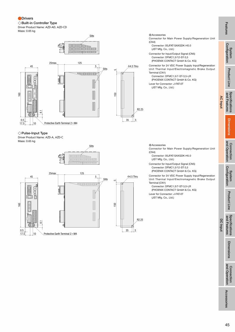
45
Features
System
C
onfig
uration
DC
Input
Pro
duct Line
Sp
ecifications
and F
eaturesC
onnectio
n and
Op
eration
Accesso
ries
AC
Input
System
C
onfig
uration
Pro
duct Line
Sp
ecifications
and F
eaturesD
imensio
nsC
onnectio
n and
Op
eration
Dim
ensions
AC
Input
●Drivers ◇Built-in Controller Type
Driver Product Name: AZD-AD, AZD-CDMass: 0.65 kg
512525max.
535
515
0
R2.25
45
160
17.5 10
8.1
0.5
ϕ4.5 ThruSlits
Slits
Protective Earth Terminal 2×M4
●AccessoriesConnector for Main Power Supply/Regeneration Unit (CN4) Connector: 05JFAT-SAXGDK-H5.0 (JST Mfg. Co., Ltd.)
Connector for Input/Output Signal (CN5) Connector: DFMC1,5/12-ST-3,5 (PHOENIX CONTACT GmbH & Co. KG)
Connector for 24 VDC Power Supply Input/Regeneration Unit Thermal Input/Electromagnetic Brake Output Terminal (CN1) Connector: DFMC1,5/7-ST-3,5-LR (PHOENIX CONTACT GmbH & Co. KG)
Lever for Connector: J-FAT-0T (JST Mfg. Co., Ltd.)
◇Pulse-Input TypeDriver Product Name: AZD-A, AZD-CMass: 0.65 kg
512525max.
535
515
0
R2.25
45
160
17.5 10
8.1
0.5
Slits
Slits
Protective Earth Terminal 2×M4
ϕ4.5 Thru
●AccessoriesConnector for Main Power Supply/Regeneration Unit (CN4) Connector: 05JFAT-SAXGDK-H5.0 (JST Mfg. Co., Ltd.)
Connector for Input/Output Signal (CN5) Connector: DFMC1,5/12-ST-3,5 (PHOENIX CONTACT GmbH & Co. KG)
Connector for 24 VDC Power Supply Input/Regeneration Unit Thermal Input/Electromagnetic Brake Output Terminal (CN1) Connector: DFMC1,5/7-ST-3,5-LR (PHOENIX CONTACT GmbH & Co. KG)
Lever for Connector: J-FAT-0T (JST Mfg. Co., Ltd.)

46
●Cable for Motor (sold separately), Cable for Encoder (sold separately), Cable for Electromagnetic Brake (sold separately) ●Only products with included connection cables
◇Cable for Motor
Cable Type Length L (m)
Cable for Motor 1 m 1
Cable for Motor 2 m 2
Cable for Motor 3 m 3
5559-06P-210(Molex) F32FSS-05V-KX(JST)
( 40)
22.8 7.15ϕ6.
4
150+20 0
( 23)
(12) 23.9L
Driver SideMotor Side
Ring crimp terminal with insulation coating (1.25–4)
◇Cable for Encoder
Cable Type Length L (m)
Cable for Encoder 1 m 1
Cable for Encoder 2 m 2
Cable for Encoder 3 m 312.2 12.243.5max.
18.8
18.8
43.5L
ϕ6.5500655-0609(Molex) 500654-0609(Molex)
Motor Side Driver Side
◇Cable for Electromagnetic Brake (Only for electromagnetic brake products)
Cable Type Length L (m)
Cable for Electromagnetic Brake 1 m 1
Cable for Electromagnetic Brake 2 m 2
Cable for Electromagnetic Brake 3 m 3
23.9L
80ϕ4.
1
(14)
( 12)
Motor Side Driver Side
5559-02P-210(Molex)
Stick Terminal:AI0.5-10WH(PHOENIX CONTACT GmbH & Co. KG)
Notes ●The motor cable and the electromagnetic brake cable coming out of the motor cannot be connected directly to the driver. For connection to the driver use the accessory connection cable (sold separately) or the connection cable which is included to the product (for products with included cable).

47
Features
System
C
onfig
uration
DC
Input
Pro
duct Line
Sp
ecifications
and F
eaturesA
ccessories
AC
Input
System
C
onfig
uration
Pro
duct Line
Sp
ecifications
and F
eaturesD
imensio
nsC
onnectio
n and
Op
eration
Dim
ensions
AC
Input
Co
nnection
and O
peratio
n
■Connection and Operation (Built-in Controller Type)
●Name and Functions of Driver Parts
Main Power Supply Input Terminal (CN4)
1 Signal Monitor Display
2 Address Number Setting Switch (ID)
3 Communication Speed Setting Switch (BAUD)
4 Function Setting Switch (SW1)
5 Termination Resistor Setting Switch (TERM)
HOME PRESET Switch
USB Communication Connector
RS-485 Communication Connector (CN6 and CN7)
6 Input/Output Signal Connector (CN5)
Protective Earth Terminal
7 24 VDC Power Supply Input Terminal (CN1)Electromagnetic Brake Terminal (CN1)
Regeneration Unit Thermal Input Terminal (CN1)
Power Cutoff Signal Input Terminal (CN1)
Power Cutoff Monitor Output Terminal (CN1)
Encoder Connector (CN2)
Motor Connector (CN3)
Regeneration Unit Connection Terminal (CN4)
Signal Monitor Displays ◇LED Displays
Display Colour Function When Activated
PWR Green Power Display When 24 VDC power is on.
ALM Red Alarm Display Blinks when protective functions are activated.
C-DAT Green Communication Display When communication data is received or sent.
C-ERR Red Communication Error Display When there is an error with communication data.
Address Number Setting Switch (ID)
Display Function
ID Set the address number for RS-485 communication (Factory Setting: 0).
Communication Speed Setting Switch
Display Function
BAUD Set this when using RS-485 communications. Set the communication speed (Factory Setting: 7).
Function Setting Switch
Display No. Function
SW11
This sets the address number in combination with the address number setting switch (ID) (Factory Setting: OFF).
2 This sets the protocol for RS-485 communication (Factory Setting: OFF).
◇Settings of the RS-485 Communication Speed
No. Baud Rate (bps)
0 9600
1 19200
2 38400
3 57600
4 115200
5 230400
6 Not used
7 Network Converter
8–F Not used

48
Termination Resistor Setting Switch
Display No. Function
TERM1 Set the RS-485 communication terminal resistor (120Ω) (Factory Setting: OFF) .
OFF: no terminal resistor, ON: terminal resistor connected.2 Please use the same settings for both No. 1 and No. 2.
Input/Output Signal Connector (CN5)
Display Pin Number Signal Name Content
CN5
1 IN0 START This signal is used to start positioning operation.
2 IN2 M1 Use the 3 bits of M0, M1, M2, to select the drive data No.
3 IN4 ZHOME Move to the home position set with the HOME PRESET switch.
4 IN6 STOP Stop the motor.
5 IN-COM [0–7]✽1 IN0~IN7 input common
6 IN8 FW-JOG Start JOG operation.
7 OUT0 HOME-END Output when determining the home position or completing high speed return-to-home operation.
8 OUT2 PLS-RDY Not used
9 OUT4 MOVE Output while operating the motor.
10 OUT-COM✽1 Output common
11 ASG+ A phase pulse output+
12 BSG+ B phase pulse output+
13 IN1 M0 Use the 3 bits of M0, M1, M2, to select the drive data No.
14 IN3 M2 Use the 3 bits of M0, M1, M2, to select the drive data No.
15 IN5 FREE The motor is set to non-excitation.
16 IN7 ALM-RST Reset the alarm.
17 IN-COM [8-9]✽1 IN8, IN9 input common
18 IN9 RV-JOG Start JOG operation.
19 OUT1 IN-POS Output when the motor operation is complete.
20 OUT3 READY Output when the driver is ready for operation.
21 OUT5 ALM-B Output the driver alarm state (normal close).
22 GND✽1 Ground
23 ASG− A phase pulse output −
24 BSG− B phase pulse output −
●Assigned functions are set by means of the parameter settings. The above is the initial value. For details, refer to the User's Manual. ✽1 The initial value setting cannot be changed.
24 VDC Input/Electromagnetic Brake Connection Terminal/Regeneration Unit Thermal Input/Power Cutoff Signal Input Terminal/Power Cutoff Monitor Output Terminal (CN1)
Display Input/Output Terminal Name Content
+24 VInput
24 VDC Power Input Terminal+This is the driver control circuit power. Be sure to connect this.
0 V 24 VDC Power Input Terminal−
MB1Output
Electromagnetic Brake Connection Terminal−Connect the cable for Electromagnetic Brake Connection Terminal.
MB2 Electromagnetic Brake Connection Terminal+
TH1Input
Regeneration Unit Thermal Input TerminalConnect the optional regenerative resistance (RGB100) (sold separately).When not connecting the regenerative resistance, short circuit between the terminals (RGB100).
TH2 Regeneration Unit Thermal Input Terminal
HWTO1+
Input
Drive Cutoff Signal Input Terminal 1+
Connect the switch and programmable controller.When either HWTO1 input or HWTO2 input is OFF, the electricity to the motor is cut directly by hard-ware without the CPU.
HWTO1− Drive Cutoff Signal Input Terminal 1−
HWTO2+ Drive Cutoff Signal Input Terminal 2+
HWTO2− Drive Cutoff Signal Input Terminal 2−
EDM+Output
Drive Cutoff Signal Input Terminal+Connect the programmable controller.When both HWTO1 input and HWTO2 input are OFF, EDM output becomes ON.
EDM− Drive Cutoff Signal Input Terminal−
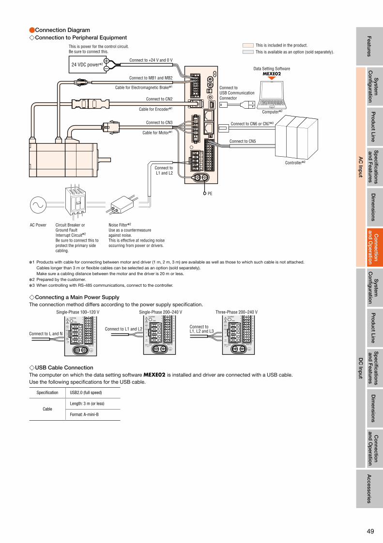
49
Features
System
C
onfig
uration
DC
Input
Pro
duct Line
Sp
ecifications
and F
eaturesD
imensio
nsA
ccessories
AC
Input
System
C
onfig
uration
Pro
duct Line
Sp
ecifications
and F
eaturesD
imensio
nsC
onnectio
n and
Op
eration
Co
nnection
and O
peratio
n
AC
Input
●Connection Diagram ◇Connection to Peripheral Equipment
This is included in the product.
This is available as an option (sold separately).
Connect to CN3
Connect to MB1 and MB2
Connect to CN5
PE
Connect to +24 V and 0 V
Cable for Motor✽1
Connect to CN2
Cable for Encoder✽1
Cable for Electromagnetic Brake✽1
Connect toL1 and L2
24 VDC power✽2
Connect to CN6 or CN7✽3
Connect to USB Communication Connector
Controller✽2
Computer✽2
Data Setting SoftwareMEXE02
AC Power Circuit Breaker orGround FaultInterrupt Circuit✽2
Be sure to connect this to protect the primary side cabling.
Noise Filter✽2
Use as a countermeasure against noise.This is effective at reducing noise occurring from power or drivers.
This is power for the control circuit.Be sure to connect this.
✽1 Products with cable for connecting between motor and driver (1 m, 2 m, 3 m) are available as well as those to which such cable is not attached. Cables longer than 3 m or flexible cables can be selected as an option (sold separately). Make sure a cabling distance between the motor and the driver is 20 m or less.
✽2 Prepared by the customer. ✽3 When controlling with RS-485 communications, connect to the controller.
◇Connecting a Main Power SupplyThe connection method differs according to the power supply specification.
Single-Phase 100–120 V Single-Phase 200–240 V Three-Phase 200–240 V
Connect to L and NConnect to L1 and L2 Connect to
L1, L2 and L3
◇USB Cable ConnectionThe computer on which the data setting software MEXE02 is installed and driver are connected with a USB cable.Use the following specifications for the USB cable.
Specification USB2.0 (full speed)
CableLength: 3 m (or less)
Format: A-mini-B

50
◇Connecting to a Host Controller ●Connecting to a Current Sink Output Circuit
IN4 (ZHOME)
IN3 (M2)
IN2 (M1)
IN1 (M0)
IN0 (START)
OUT0 (HOME-END)
OUT1 (IN-POS)
OUT2 (PLS-RDY)
OUT3 (READY)
OUT4 (MOVE)
OUT5 (ALM-B)
OUT-COM
IN5 (FREE)
IN6 (STOP)
IN7 (ALM-RST)
IN-COM[ 0-7]
IN8 (FW-JOG)
IN9 (RV-JOG)
IN-COM[ 8-9]
ASG-
ASG+
BSG-
BSG+
GND
4.7 kΩ 2.2 kΩ
4.7 kΩ 2.2 kΩ
4.7 kΩ 2.2 kΩ
4.7 kΩ 2.2 kΩ
4.7 kΩ 2.2 kΩ
4.7 kΩ 2.2 kΩ
4.7 kΩ 2.2 kΩ
4.7 kΩ 2.2 kΩ
0 V
0 V
0 V
24 VDC
12~24 VDC
R0
R0
R0
R0
R0
R0
0 V
2.2 kΩ
4.7 kΩ
4.7 kΩ
2.2 kΩ24 VDC
0 V17
18
19
20
21
22
23
24
9
10
11
12
13
14
15
16
8
1
2
3
4
5
6
7
Twisted-pair cable
DriverController
Output SaturationVoltage3 VDC max.
26C31 or equivalent
10 mA or less→
Notes ●For the input signal, use 24 VDC. ●For the output signal, use 12∼24 VDC 10 mA or less. Where the current value exceeds 10 mA, connect an external resistor R0 to reduce the current to 10 mA or less. ●Make sure the signal line is wired at a distance of 200 mm or longer from the power lines (power supply line and motor line).
Further, do not insert the signal line in the same pipe as the power lines or bundle them together. ●When noise is emitted from the motor cable or power cable due to wiring or allocation and it cause a problem, use shields or ferrite cores.

51
Features
System
C
onfig
uration
DC
Input
Pro
duct Line
Sp
ecifications
and F
eaturesD
imensio
nsA
ccessories
AC
Input
System
C
onfig
uration
Pro
duct Line
Sp
ecifications
and F
eaturesD
imensio
nsC
onnectio
n and
Op
eration
Co
nnection
and O
peratio
n
AC
Input
◇Connecting to a Host Controller ●Connecting to a Current Source Output Circuit
IN4 (ZHOME)
IN3 (M2)
IN2 (M1)
IN1 (M0)
IN0 (START)
OUT0 (HOME-END)
OUT1 (IN-POS)
OUT2 (PLS-RDY)
OUT3 (READY)
OUT4 (MOVE)
OUT5 (ALM-B)
OUT-COM
IN5 (FREE)
IN6 (STOP)
IN7 (ALM-RST)
IN-COM [0-7]
IN8 (FW-JOG)
IN9 (RV-JOG)
IN-COM [8-9]
ASG-
ASG+
BSG-
BSG+
GND
4.7 kΩ 2.2 kΩ
4.7 kΩ 2.2 kΩ
4.7 kΩ 2.2 kΩ
4.7 kΩ 2.2 kΩ
4.7 kΩ 2.2 kΩ
4.7 kΩ 2.2 kΩ
4.7 kΩ 2.2 kΩ
4.7 kΩ 2.2 kΩ
0 V
0 V
0 V
24 VDC
12~24 VDC R0
R0
R0
R0
R0
R0
0 V
4.7 kΩ 2.2 kΩ
4.7 kΩ 2.2 kΩ
24 VDC
0 V17
18
19
20
21
22
23
24
9
10
11
12
13
14
15
16
8
1
2
3
4
5
6
7
Twisted-pair cable
DriverController
10 mA or less
Output SaturationVoltage3 VDC max.
26C31 or equivalent
→
Notes ●For the input signal, use 24 VDC. ●For the output signal, use 12∼24 VDC 10 mA or less. Where the current value exceeds 10 mA, connect an external resistor R0 to reduce the current to 10 mA or less. ●Make sure the signal line is wired at a distance of 200 mm or longer from the power line (power supply line and motor line).
Further, do not insert the signal line in the same pipe as the power lines or bundle them together. ●When noise is emitted from the motor cable or power cable due to wiring or allocation and it cause a problem, use shields or ferrite cores.

52
■Connection and Operation (Pulse-Input Type)
●Names and Functions of Driver Parts
Main Power Supply Input Terminal (CN4)
1 Signal Monitor Display
2 Current Setting Switch (CURRENT)
3 Instruction Filter Setting Switch (FIL)
4 Function Setting Switch (SW1)
HOME PRESET Switch
USB Communication Connector
5 Input/Output Signal Connector (CN5)
Protective Earth Terminal
6 24 VDC Power Supply Input Terminal(CN1)Electromagnetic Brake Terminal (CN1)
Regeneration Unit Thermal Input Terminal (CN1)
Power Cutoff Signal Input Terminal (CN1)
Power Cutoff Monitor Output Terminal (CN1)
Encoder Connector (CN2)
Motor Connector (CN3)
Regeneration Unit Connection Terminal (CN4)
Signal Monitor Displays ◇LED Display
Display Colour Function When Activated
PWR Green Power Display When 24 VDC power is on.
ALM Red Alarm Display Blinks when protective functions are activated.
READY Green READY Output When READY output is set to ON.
Current Setting Switch
Display Function
CURRENT Set basic current that is the base for the operation current and stop current (Factory Setting: F).
Command Filter Setting Switch
Display Function
FIL Adjust the responsiveness of the motor (Factory Setting: 1).
Function Setting Switch
Display No. Function
SW1
1Sets the resolution per one rotation of the motor output shaft: OFF [1000 p/r] (Factory Setting); ON [10000 p/r]
2Sets the pulse input format to 1 pulse input mode or 2 pulse input mode.(Factory Setting: OFF[2 pulse input mode])
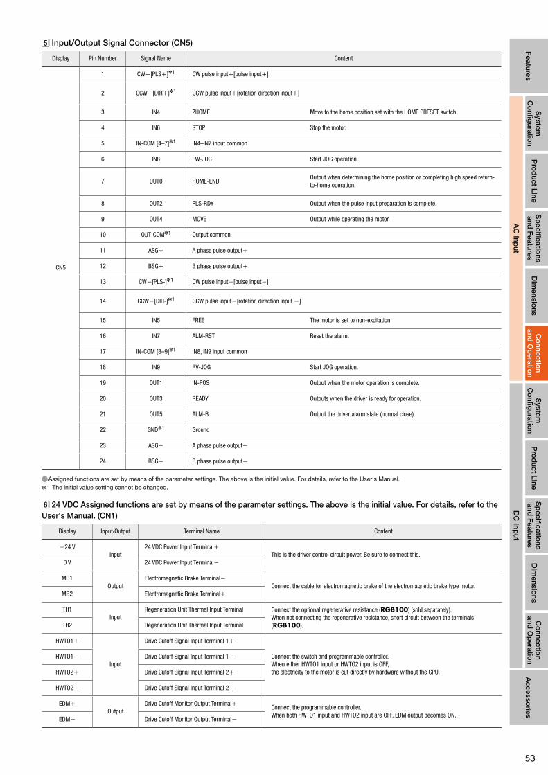
53
Features
System
C
onfig
uration
DC
Input
Pro
duct Line
Sp
ecifications
and F
eaturesD
imensio
nsA
ccessories
AC
Input
System
C
onfig
uration
Pro
duct Line
Sp
ecifications
and F
eaturesD
imensio
nsC
onnectio
n and
Op
eration
Co
nnection
and O
peratio
n
AC
Input
Input/Output Signal Connector (CN5)
Display Pin Number Signal Name Content
CN5
1 CW+[PLS+]✽1 CW pulse input+[pulse input+]
2 CCW+[DIR+]✽1 CCW pulse input+[rotation direction input+]
3 IN4 ZHOME Move to the home position set with the HOME PRESET switch.
4 IN6 STOP Stop the motor.
5 IN-COM [4–7]✽1 IN4–IN7 input common
6 IN8 FW-JOG Start JOG operation.
7 OUT0 HOME-ENDOutput when determining the home position or completing high speed return-to-home operation.
8 OUT2 PLS-RDY Output when the pulse input preparation is complete.
9 OUT4 MOVE Output while operating the motor.
10 OUT-COM✽1 Output common
11 ASG+ A phase pulse output+
12 BSG+ B phase pulse output+
13 CW−[PLS-]✽1 CW pulse input−[pulse input−]
14 CCW−[DIR-]✽1 CCW pulse input−[rotation direction input −]
15 IN5 FREE The motor is set to non-excitation.
16 IN7 ALM-RST Reset the alarm.
17 IN-COM [8–9]✽1 IN8, IN9 input common
18 IN9 RV-JOG Start JOG operation.
19 OUT1 IN-POS Output when the motor operation is complete.
20 OUT3 READY Outputs when the driver is ready for operation.
21 OUT5 ALM-B Output the driver alarm state (normal close).
22 GND✽1 Ground
23 ASG− A phase pulse output−
24 BSG− B phase pulse output−
●Assigned functions are set by means of the parameter settings. The above is the initial value. For details, refer to the User's Manual. ✽1 The initial value setting cannot be changed.
24 VDC Assigned functions are set by means of the parameter settings. The above is the initial value. For details, refer to the User's Manual. (CN1)
Display Input/Output Terminal Name Content
+24 VInput
24 VDC Power Input Terminal+This is the driver control circuit power. Be sure to connect this.
0 V 24 VDC Power Input Terminal−
MB1Output
Electromagnetic Brake Terminal−Connect the cable for electromagnetic brake of the electromagnetic brake type motor.
MB2 Electromagnetic Brake Terminal+
TH1Input
Regeneration Unit Thermal Input Terminal Connect the optional regenerative resistance (RGB100) (sold separately).When not connecting the regenerative resistance, short circuit between the terminals (RGB100).TH2 Regeneration Unit Thermal Input Terminal
HWTO1+
Input
Drive Cutoff Signal Input Terminal 1+
Connect the switch and programmable controller.When either HWTO1 input or HWTO2 input is OFF,the electricity to the motor is cut directly by hardware without the CPU.
HWTO1− Drive Cutoff Signal Input Terminal 1−
HWTO2+ Drive Cutoff Signal Input Terminal 2+
HWTO2− Drive Cutoff Signal Input Terminal 2−
EDM+Output
Drive Cutoff Monitor Output Terminal+Connect the programmable controller.When both HWTO1 input and HWTO2 input are OFF, EDM output becomes ON.
EDM− Drive Cutoff Monitor Output Terminal−

54
●Connection Diagram ◇Connection to Peripheral Equipment
Connect to USB Communication Connector
This is included in the product.
This is available as an option (sold separately).
Connect to CN3
Connect to MB1 and MB2
Connect to CN5
PE
Connect to +24 V and 0 V
Cable for Motor✽1
Connect to CN2
Cable for Encoder✽1
Cable for Electromagnetic brake✽1
Connect toL1 and L2
24 VDC power✽2
Controller✽2
Computer✽2
Data Setting SoftwareMEXE02
AC Power Circuit Breaker orGround FaultInterrupt Circuit✽2
Be sure to connect this to protect the primary side cabling.
Noise filter✽2
Use as a countermeasure against noise.This is effective at reducing noise occurring from power or drivers.
This is power for the control circuit.Be sure to connect this.
✽1 Products with cable for connecting between motor and driver (1 m, 2 m, 3 m) are available as well as those to which such cable is not attached.Cables longer than 3 m or flexible cables can be selected as an option (sold separately).Make sure a cabling distance between the motor and the driver is 20 m or less.
✽2 Prepared by the customer.
◇Connecting a Main Power SupplyThe connection method differs according to the power supply specification.
Single-Phase 100–120 V Single-Phase 200–240 V Three-Phase 200–240 V
Connect to L and NConnect to L1 and L2 Connect to
L1, L2 and L3
◇USB Cable ConnectionThe computer on which the data setting software MEXE02 is installed and driver are connected with a USB cable.Use the following specifications for the USB cable.
Specification USB2.0 (full speed)
CableLength: 3 m (or less)
Format: A-mini-B

55
Features
System
C
onfig
uration
DC
Input
Pro
duct Line
Sp
ecifications
and F
eaturesD
imensio
nsA
ccessories
AC
Input
System
C
onfig
uration
Pro
duct Line
Sp
ecifications
and F
eaturesD
imensio
nsC
onnectio
n and
Op
eration
Co
nnection
and O
peratio
n
AC
Input
◇Connecting to a Host Controller ●Connecting to a Current Sink Output Circuit
When the pulse input is a line driver
0 V
CW (PLS)+
CW (PLS)-
CCW (DIR)+
IN4 (ZHOME)
OUT0 (HOME-END)
OUT1 (IN-POS)
OUT2 (PLS-RDY)
OUT3 (READY)
OUT4 (MOVE)
OUT5 (ALM-B)
OUT-COM
IN5 (FREE)
IN6 (STOP)
IN7 (ALM-RST)
IN-COM [4-7]
IN8 (FW-JOG)
IN9 (RV-JOG)
IN-COM [8-9]
CCW (DIR)-
ASG-
ASG+
BSG-
BSG+
GND
100 Ω
100 Ω
2.2 kΩ
100 Ω
100 Ω
2.2 kΩ
4.7 kΩ
2.2 kΩ
4.7 kΩ
2.2 kΩ
4.7 kΩ
2.2 kΩ
4.7 kΩ
2.2 kΩ
0 V
0 V
0 V
24 VDC
12~24 VDC
R0
R0
R0
R0
R0
R0
0 V
2.2 kΩ
4.7 kΩ
4.7 kΩ
2.2 kΩ24 VDC
0 V17
18
19
20
21
22
23
24
9
10
11
12
13
14
15
16
8
1
2
3
4
5
6
7
DriverController
10 mA or less→
OutputSaturationVoltage3 VDC max.
26C31 or equivalent
Twisted-pair cable
When the pulse input is an open collector
CW(PLS)+
CW(PLS)-
CCW(DIR)+
CCW(DIR)-
100 Ω
100 Ω
2.2 kΩ
100 Ω
100 Ω
R1
R1
2.2 kΩ
5–24 VDC
0 V
13
14
1
2
Driver
Twisted-pair cable
Controller
Notes ●For the input signal, use 24 VDC. ●For the output signal, use 12∼24 VDC 10 mA or less. Where the current value exceeds 10 mA, connect the external resistance R0 to reduce the current to 10 mA or less. ●Make sure the signal line is wired at a distance of 200 mm or longer from the power line (power supply line and motor line).Furthermore, do not insert the signal line in the same pipe as the power lines or bundle them together. ●When noise is emitted from the motor cable or power cable due to wiring or allocation and it cause a problem, use shields or ferrite cores.
Notes ●For CW (PLS) input and CCW (DIR) input, use 5∼24 VDC. Where the voltage exceeds 5 VDC, connect the external resistance R1 to adjust the input current to be 7∼20 mA.

56
◇Connecting to a Host Controller ●Connecting to a Current Source Output Circuit
When the pulse input is a line driver
0 V
CW (PLS)+
CW (PLS)-
CCW (DIR)+
IN4 (ZHOME)
OUT0 (HOME-END)
OUT1 (IN-POS)
OUT2 (PLS-RDY)
OUT3 (READY)
OUT4 (MOVE)
OUT5 (ALM-B)
OUT-COM
IN5 (FREE)
IN6 (STOP)
IN7 (ALM-RST)
IN-COM[4-7]
IN8 (FW-JOG)
IN9 (RV-JOG)
IN-COM[8-9]
CCW (DIR)-
ASG-
ASG+
BSG-
BSG+
GND
100 Ω
100 Ω
2.2 kΩ
100 Ω
100 Ω
2.2 kΩ
4.7 kΩ
2.2 kΩ
4.7 kΩ
2.2 kΩ
4.7 kΩ
2.2 kΩ
4.7 kΩ
2.2 kΩ
0 V
0 V
0 V
24 VDC
12~24 VDC R0
R0
R0
R0
R0
R0
0 V
4.7 kΩ
2.2 kΩ
4.7 kΩ
2.2 kΩ
24 VDC
0 V
13
14
1
2
3
17
18
15
16
4
5
6
19
20
21
22
23
24
9
10
11
12
8
7
DriverController
←10 mA or less
26C31 or equivalent
OutputSaturationVoltage3 VDC max.
Twisted-pair cable
When the pulse input is an open collector
CW(PLS)+
CW(PLS)-
CCW(DIR)+
CCW(DIR)-
100 Ω
100 Ω
2.2 kΩ
100 Ω
100 Ω
R1
R1 2.2 kΩ
5–24 VDC
0 V
13
14
1
2
DriverController
Twisted-pair cable
Notes ●For the input signal, use 24 VDC. ●For the output signal, use 12∼24 VDC 10 mA or less. Where the current value exceeds 10 mA, connect to external resistance R0 to reduce the current to 10 mA or less. ●Make sure the signal line is wired at a distance of 200 mm or longer from the power line (power supply line and motor line).Furthermore, do not insert the signal line in the same pipe as the power lines or bundle them together. ●When noise is emitted from the motor cable or power cable due to wiring or allocation and it cause a problem, use shields or ferrite cores.
Notes ●For CW (PLS) input and CCW (DIR) input, use 5∼24 VDC. Where the voltage exceeds 5 VDC, connect the external resistance R1 to adjust the input current to be 7∼20 mA.
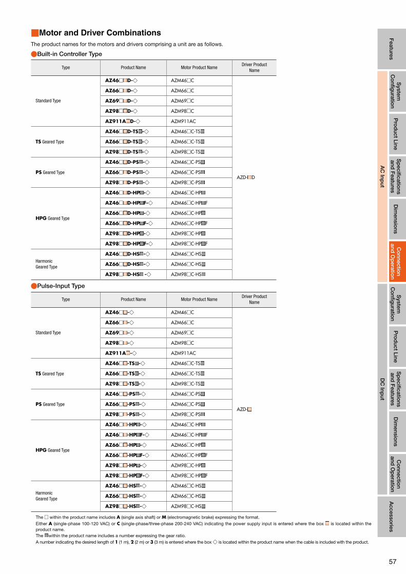
57
Features
System
C
onfig
uration
DC
Input
Pro
duct Line
Sp
ecifications
and F
eaturesD
imensio
nsA
ccessories
AC
Input
System
C
onfig
uration
Pro
duct Line
Sp
ecifications
and F
eaturesD
imensio
nsC
onnectio
n and
Op
eration
Co
nnection
and O
peratio
n
AC
Input
■Motor and Driver Combinations
The product names for the motors and drivers comprising a unit are as follows.
●Built-in Controller Type
Type Product Name Motor Product NameDriver Product
Name
Standard Type
AZ46□ ■ D-◇ AZM46□C
AZD- ■ D
AZ66□ ■ D-◇ AZM66□C
AZ69□ ■ D-◇ AZM69□C
AZ98□ ■ D-◇ AZM98□C
AZ911A ■ D-◇ AZM911AC
TS Geared Type
AZ46□ ■ D-TS ■ -◇ AZM46□C-TS ■
AZ66□ ■ D-TS ■ -◇ AZM66□C-TS ■
AZ98□ ■ D-TS ■ -◇ AZM98□C-TS ■
PS Geared Type
AZ46□ ■ D-PS ■ -◇ AZM46□C-PS ■
AZ66□ ■ D-PS ■ -◇ AZM66□C-PS ■
AZ98□ ■ D-PS ■ -◇ AZM98□C-PS ■
HPG Geared Type
AZ46□ ■ D-HP ■ -◇ AZM46□C-HP ■
AZ46□ ■ D-HP ■ F-◇ AZM46□C-HP ■ F
AZ66□ ■ D-HP ■ -◇ AZM66□C-HP ■
AZ66□ ■ D-HP ■ F-◇ AZM66□C-HP ■ F
AZ98□ ■ D-HP ■ -◇ AZM98□C-HP ■
AZ98□ ■ D-HP ■ F-◇ AZM98□C-HP ■ F
Harmonic Geared Type
AZ46□ ■ D-HS ■ -◇ AZM46□C-HS ■
AZ66□ ■ D-HS ■ -◇ AZM66□C-HS ■
AZ98□ ■ D-HS ■ -◇ AZM98□C-HS ■
●Pulse-Input Type
Type Product Name Motor Product NameDriver Product
Name
Standard Type
AZ46□ ■ -◇ AZM46□C
AZD- ■
AZ66□ ■ -◇ AZM66□C
AZ69□ ■ -◇ AZM69□C
AZ98□ ■ -◇ AZM98□C
AZ911A ■ -◇ AZM911AC
TS Geared Type
AZ46□ ■ -TS ■ -◇ AZM46□C-TS ■
AZ66□ ■ -TS ■ -◇ AZM66□C-TS ■
AZ98□ ■ -TS ■ -◇ AZM98□C-TS ■
PS Geared Type
AZ46□ ■ -PS ■ -◇ AZM46□C-PS ■
AZ66□ ■ -PS ■ -◇ AZM66□C-PS ■
AZ98□ ■ -PS ■ -◇ AZM98□C-PS ■
HPG Geared Type
AZ46□ ■ -HP ■ -◇ AZM46□C-HP ■
AZ46□ ■ -HP ■ F-◇ AZM46□C-HP ■ F
AZ66□ ■ -HP ■ -◇ AZM66□C-HP ■
AZ66□ ■ -HP ■ F-◇ AZM66□C-HP ■ F
AZ98□ ■ -HP ■ -◇ AZM98□C-HP ■
AZ98□ ■ -HP ■ F-◇ AZM98□C-HP ■ F
Harmonic Geared Type
AZ46□ ■ -HS ■ -◇ AZM46□C-HS ■
AZ66□ ■ -HS ■ -◇ AZM66□C-HS ■
AZ98□ ■ -HS ■ -◇ AZM98□C-HS ■
The □ within the product name includes A (single axis shaft) or M (electromagnetic brake) expressing the format.Either A (single-phase 100-120 VAC) or C (single-phase/three-phase 200-240 VAC) indicating the power supply input is entered where the box ■ is located within the product name.The ■ within the product name includes a number expressing the gear ratio.A number indicating the desired length of 1 (1 m), 2 (2 m) or 3 (3 m) is entered where the box ◇ is located within the product name when the cable is included with the product.

5858
Motor Driver
Products are available with connection cables of 1 m, 2 m or 3 m length (for motor, for encoder and for electromagnetic brake) or without cable.
AZ Series
For encoder
For motor
For electromagnetic brake
Motor Mounting Brackets➜ page 104
Cable for RS-485 Communications ➜ page 101
General-Purpose Cable for Input/Output Signals ➜ page 101
●System Configuration Example
AZ SeriesSold Separately
Motor Mounting Bracket Flexible CouplingGeneral-Purpose Cable
(1 m)AZ66MKD-3 PAL2P-5 MCV251010 CC16D010B-1
●The system configuration described above is just an example. Other combinations are available.
Options (sold separately)
Computer✽1
To USB Port
Data Setting Software
MEXE02(For RS-485 Communication)
Network Converter ➜ page 107
■System Configuration
●Built-in Controller Type with Electromagnetic BrakeConfiguration example when using I/O control or RS-485 communications. ✽1 Prepared by the customer.
✽2 Only products to which the connection cables are attached.
For less vibrations When extending between the motor and driver without using attached connection cables✽2
When extending between the motor and driver using attached connection cables✽2
MCV Coupling ➜ page 102
For motor For encoder For electromagnetic
brake
For motor For encoder For electromagnetic
brake
Connection Cable Set Flexible Connection Cable Set
➜ page 98
Extension Cable Set Flexible Extension Cable Set
➜ page 99
Options (sold separately)
or
DC Power Supply ✽1 (Main power supply)
Programmable Controller✽1
Related Products (sold separately)
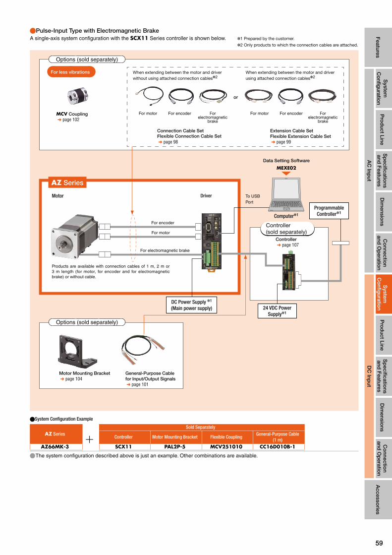
5959
Features
System
C
onfig
uration
Pro
duct Line
Sp
ecifications
and F
eaturesD
imensio
nsC
onnectio
n and
Op
eration
Accesso
ries
AC
Input
Pro
duct Line
Sp
ecifications
and F
eaturesD
imensio
nsC
onnectio
n and
Op
eration
System
C
onfig
uration
DC
Input
Motor Driver
Products are available with connection cables of 1 m, 2 m or 3 m length (for motor, for encoder and for electromagnetic brake) or without cable.
Controller ➜ page 107
●System Configuration Example
AZ SeriesSold Separately
Controller Motor Mounting Bracket Flexible CouplingGeneral-Purpose Cable
(1 m)AZ66MK-3 SCX11 PAL2P-5 MCV251010 CC16D010B-1
●The system configuration described above is just an example. Other combinations are available.
Motor Mounting Bracket ➜ page 104
General-Purpose Cable for Input/Output Signals ➜ page 101
AZ Series
Options (sold separately)
Computer✽1
To USB Port
Data Setting Software
MEXE02
Programmable Controller✽1
●Pulse-Input Type with Electromagnetic BrakeA single-axis system configuration with the SCX11 Series controller is shown below. ✽1 Prepared by the customer.
✽2 Only products to which the connection cables are attached.
For less vibrations When extending between the motor and driver without using attached connection cables✽2
When extending between the motor and driver using attached connection cables✽2
MCV Coupling ➜ page 102
For motor For encoder For electromagnetic
brake
For motor For encoder For electromagnetic
brake
Connection Cable Set Flexible Connection Cable Set
➜ page 98
Extension Cable Set Flexible Extension Cable Set
➜ page 99
Options (sold separately)
or
For encoder
For motor
For electromagnetic brake
DC Power Supply ✽1 (Main power supply) 24 VDC Power
Supply✽1
Controller (sold separately)

6060
■Product Number Code
●Standard Type
① ② ③ ⑩④ ⑥⑤
AZ 6 6 A K D - 1
● Geared Types
① ② ⑧③ ⑦④ ⑥⑤ ⑨ ⑩
AZ 6 6 A K D - HP 15 F - 1
① Series Name AZ: AZ Series
② Motor Frame Size
1: 20 mm 2: 28 mm 4: 42mm (HPG Geared Type is 40 mm) 6: 60 mm
③ Motor Case Length
④ Configuration A: Single Shaft M: With Electromagnetic Brake
⑤ Power Supply Input K: 24 VDC Power Supply
⑥ Driver Type D: Built-in Controller Type None: Pulse-Input Type
⑦ Geared Type
TS: TS Geared TypePS: PS Geared TypeHP: HPG Geared TypeHS: Harmonic Geared Type
⑧ Gear Ratio
⑨ Output Shaft Type HPG Geared Type None: Shaft Output F: Flange Output
⑩ Connection CablesFigures: Included Connection Cable Length1 : 1m 2 : 2m 3 : 3mNone: Connection Cable not included
■Product Line
●Built-in Controller Type ◇Standard Type
Product Name
AZ14AKD-◇ AZ15AKD-◇ AZ24AKD-◇ AZ26AKD-◇ AZ46AKD-◇ AZ66AKD-◇ AZ69AKD-◇
◇TS Geared Type
Product Name
AZ46AKD-TS3.6-◇ AZ46AKD-TS7.2-◇ AZ46AKD-TS10-◇ AZ46AKD-TS20-◇ AZ46AKD-TS30-◇ AZ66AKD-TS3.6-◇ AZ66AKD-TS7.2-◇ AZ66AKD-TS10-◇ AZ66AKD-TS20-◇ AZ66AKD-TS30-◇
◇Standard Type with Electromagnetic Brake
Product Name
AZ46MKD-◇ AZ66MKD-◇ AZ69MKD-◇
◇TS Geared Type with Electromagnetic Brake
Product Name
AZ46MKD-TS3.6-◇ AZ46MKD-TS7.2-◇ AZ46MKD-TS10-◇ AZ46MKD-TS20-◇ AZ46MKD-TS30-◇ AZ66MKD-TS3.6-◇ AZ66MKD-TS7.2-◇ AZ66MKD-TS10-◇ AZ66MKD-TS20-◇ AZ66MKD-TS30-◇

6161
Features
System
C
onfig
uration
Pro
duct Line
Sp
ecifications
and F
eaturesD
imensio
nsC
onnectio
n and
Op
eration
Accesso
ries
AC
Input
System
C
onfig
uration
Sp
ecifications
and F
eaturesD
imensio
nsC
onnectio
n and
Op
eration
Pro
duct Line
DC
Input
◇PS Geared Type
Product Name
AZ46AKD-PS5-◇ AZ46AKD-PS7.2-◇ AZ46AKD-PS10-◇ AZ46AKD-PS25-◇ AZ46AKD-PS36-◇ AZ46AKD-PS50-◇ AZ66AKD-PS5-◇ AZ66AKD-PS7.2-◇ AZ66AKD-PS10-◇ AZ66AKD-PS25-◇ AZ66AKD-PS36-◇ AZ66AKD-PS50-◇
◇HPG Geared Type
Product Name
AZ46AKD-HP5-◇ AZ46AKD-HP5F-◇ AZ46AKD-HP9-◇ AZ46AKD-HP9F-◇ AZ66AKD-HP5-◇ AZ66AKD-HP5F-◇ AZ66AKD-HP15-◇ AZ66AKD-HP15F-◇
◇Harmonic Geared Type
Product Name
AZ46AKD-HS50-◇ AZ46AKD-HS100-◇ AZ66AKD-HS50-◇ AZ66AKD-HS100-◇
◇PS Geared Type with Electromagnetic Brake
Product Name
AZ46MKD-PS5-◇ AZ46MKD-PS7.2-◇ AZ46MKD-PS10-◇ AZ46MKD-PS25-◇ AZ46MKD-PS36-◇ AZ46MKD-PS50-◇ AZ66MKD-PS5-◇ AZ66MKD-PS7.2-◇ AZ66MKD-PS10-◇ AZ66MKD-PS25-◇ AZ66MKD-PS36-◇ AZ66MKD-PS50-◇
◇HPG Geared Type with Electromagnetic Brake
Product Name
AZ46MKD-HP5-◇ AZ46MKD-HP5F-◇ AZ46MKD-HP9-◇ AZ46MKD-HP9F-◇ AZ66MKD-HP5-◇ AZ66MKD-HP5F-◇ AZ66MKD-HP15-◇ AZ66MKD-HP15F-◇
◇Harmonic Geared Type with Electromagnetic Brake
Product Name
AZ46MKD-HS50-◇ AZ46MKD-HS100-◇ AZ66MKD-HS50-◇ AZ66MKD-HS100-◇
●A number indicating the desired length of 1 (1 m), 2 (2 m) or 3 (3 m) is entered where the box ◇ is located within the product name when the cable is included with the product.
The following items are included in each product.
Motor, Parallel Key✽1, Motor Installation Screws✽2, Driver, Cable for Motor ✽3, Cable for Encoder✽3, Cable for Electromagnetic Brake (units with electromagnetic brake only)✽3, Driver Connector Set and Operating Manual
✽1 Only for products with a key slot on the output shaft. ✽2 TS geared type with frame sizes 60 mm only. ✽3 Only products where connection cables are included. Accessory cables (sold separately) must be purchased in the following situations:∙ When using a flexible cable∙ When using a cable longer than 3 m∙ When purchasing a product without cable
Notes ●The motor cable and electromagnetic brake cable from the motor cannot be connected directly to the driver. When connecting to a driver, use the accessory connection cable (sold separately) or use the included connection cable.
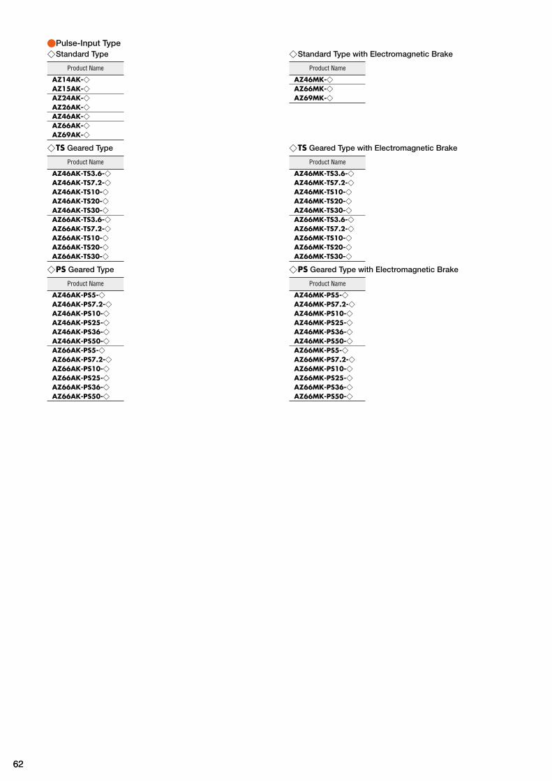
6262
●Pulse-Input Type ◇Standard Type
Product Name
AZ14AK-◇ AZ15AK-◇ AZ24AK-◇ AZ26AK-◇ AZ46AK-◇ AZ66AK-◇ AZ69AK-◇
◇TS Geared Type
Product Name
AZ46AK-TS3.6-◇ AZ46AK-TS7.2-◇ AZ46AK-TS10-◇ AZ46AK-TS20-◇ AZ46AK-TS30-◇ AZ66AK-TS3.6-◇ AZ66AK-TS7.2-◇ AZ66AK-TS10-◇ AZ66AK-TS20-◇ AZ66AK-TS30-◇
◇PS Geared Type
Product Name
AZ46AK-PS5-◇ AZ46AK-PS7.2-◇ AZ46AK-PS10-◇ AZ46AK-PS25-◇ AZ46AK-PS36-◇ AZ46AK-PS50-◇ AZ66AK-PS5-◇ AZ66AK-PS7.2-◇ AZ66AK-PS10-◇ AZ66AK-PS25-◇ AZ66AK-PS36-◇ AZ66AK-PS50-◇
◇Standard Type with Electromagnetic Brake
Product Name
AZ46MK-◇ AZ66MK-◇ AZ69MK-◇
◇TS Geared Type with Electromagnetic Brake
Product Name
AZ46MK-TS3.6-◇ AZ46MK-TS7.2-◇ AZ46MK-TS10-◇ AZ46MK-TS20-◇ AZ46MK-TS30-◇ AZ66MK-TS3.6-◇ AZ66MK-TS7.2-◇ AZ66MK-TS10-◇ AZ66MK-TS20-◇ AZ66MK-TS30-◇
◇PS Geared Type with Electromagnetic Brake
Product Name
AZ46MK-PS5-◇ AZ46MK-PS7.2-◇ AZ46MK-PS10-◇ AZ46MK-PS25-◇ AZ46MK-PS36-◇ AZ46MK-PS50-◇ AZ66MK-PS5-◇ AZ66MK-PS7.2-◇ AZ66MK-PS10-◇ AZ66MK-PS25-◇ AZ66MK-PS36-◇ AZ66MK-PS50-◇

6363
Features
System
C
onfig
uration
Pro
duct Line
Sp
ecifications
and F
eaturesD
imensio
nsC
onnectio
n and
Op
eration
Accesso
ries
AC
Input
System
C
onfig
uration
Sp
ecifications
and F
eaturesD
imensio
nsC
onnectio
n and
Op
eration
Pro
duct Line
DC
Input
◇HPG Geared Type
Product Name
AZ46AK-HP5-◇ AZ46AK-HP5F-◇ AZ46AK-HP9-◇ AZ46AK-HP9F-◇ AZ66AK-HP5-◇ AZ66AK-HP5F-◇ AZ66AK-HP15-◇ AZ66AK-HP15F-◇
◇Harmonic Geared Type
Product Name
AZ46AK-HS50-◇ AZ46AK-HS100-◇ AZ66AK-HS50-◇ AZ66AK-HS100-◇
◇HPG Geared Type with Electromagnetic Brake
Product Name
AZ46MK-HP5-◇ AZ46MK-HP5F-◇ AZ46MK-HP9-◇ AZ46MK-HP9F-◇ AZ66MK-HP5-◇ AZ66MK-HP5F-◇ AZ66MK-HP15-◇ AZ66MK-HP15F-◇
◇Harmonic Geared Type with Electromagnetic Brake
Product Name
AZ46MK-HS50-◇ AZ46MK-HS100-◇ AZ66MK-HS50-◇ AZ66MK-HS100-◇
●A number indicating the desired length of 1 (1 m), 2 (2 m) or 3 (3 m) is entered where the box ◇ is located within the product name when the cable is included with the product.
The following are included in each product.
Motor, Parallel Key✽1, Motor Installation Screws✽2, Driver, Cable for Motor ✽3, Cable for Encoder✽3, Cable for Electromagnetic Brake (units with electromagnetic brake only)✽3, Driver Connector Set and Operating Manual
✽1 Only for products with a key slot on the output shaft. ✽2 TS geared type with frame size 60mm only. ✽3 Only products where connection cables are included. Accessory cables (sold separately) must be purchased in the following situations:∙ When using a flexible cable∙ When using a cable longer than 3 m∙ When purchasing a product without cable
Notes ●The motor cable and electromagnetic brake cable from the motor cannot be connected directly to the driver. When connecting to a driver, use the accessory connection cable (sold separately) or use the included connection cable.
■How to Read the Specification Table
Maximum Holding Torque : This is the maximum holding torque (holding force) the motor has when power is supplied (at rated current) but the motor is not rotating. (With geared types, the value of holding torque considers the permissible strength of the gear).
Permissible Torque : This is the maximum torque value continuously applied to the gear output shaft.
Instantaneous Maximum Torque : This is the maximum torque value applied to the gear output shaft when accelerating and decelerating such as when starting/stopping inertial load.
Holding torque at standstill While power on: This is the holding torque in the state in which the automatic current down function is working. Electromagnetic brakes: Static friction torque that can be caused by the electromagnetic brakes when stopped. (Electromagnetic brakes are the non-excitation actuating type.)

6464
Standard Type Frame Size 20 mm, 28 mm
■Specifications
Product NameBuilt-in Controller Type AZ14AKD-◇ AZ15AKD-◇ AZ24AKD-◇ AZ26AKD-◇Pulse-Input Type AZ14AK-◇ AZ15AK-◇ AZ24AK-◇ AZ26AK-◇
Maximum Holding Torque N·m 0.02 0.036 0.095 0.19
Holding Torque at Motor Standstill N·m 0.01 0.018 0.047 0.095
Rotor Inertia J: kg·m2 2.7×10⁻⁷ 3.9×10⁻⁷ 9.2×10⁻⁷ 17×10-7
Resolution Resolution Setting: 1000P/R 0.36°/Pulse
Power Supply InputVoltage 24 VDC±5%
Input current A 0.5 0.6 1.6 1.6
●A number indicating the desired length of 1 (1 m), 2 (2 m) or 3 (3 m) is entered where the box -◇ is located within the product name when the cable is included with the product.
■Speed - Torque Characteristics (Reference Value)
AZ14 AZ15
0 20 3010 40 50 70 8060 90 100
0
0.005
0.010
0.015
0.020
0.025
0.030
0 1000 2000 3000 4000 5000 6000
Pulse Speed [kHz]Resolution Setting: 1000P/R
Speed [r/min]
Torq
ue [ N
·m]
0 20 3010 40 50 70 8060 90 100
0 1000 2000 3000 4000 5000 60000
0.01
0.02
0.03
0.04
0.05
Pulse Speed [kHz]Resolution Setting: 1000P/R
Speed [r/min]
Torq
ue [ N
·m]
AZ24 AZ26
0 20 3010 40 50 70 8060 90 100
0 1000 2000 3000 4000 5000 60000
0.02
0.04
0.06
0.08
0.10
0.12
Pulse Speed [kHz]Resolution Setting: 1000P/R
Speed [r/min]
Torq
ue [ N
·m]
0 20 3010 40 50 70 8060 90 100
0
0.05
0.10
0.15
0.20
0.25
0 1000 2000 3000 4000 5000 6000
Pulse Speed [kHz]Resolution Setting: 1000P/R
Speed [r/min]
Torq
ue [ N
·m]
Notes ●The speed-torque characteristics are data based upon our measurement conditions. When these conditions change, these characteristics may change. ●Depending on the driving conditions, a considerable amount of heat may be generated by the motor. Be sure to keep the motor case temperature at 80°C or less in order to protect the ABZO sensor.

6565
Features
System
C
onfig
uration
Pro
duct Line
Sp
ecifications
and F
eaturesD
imensio
nsC
onnectio
n and
Op
eration
Accesso
ries
AC
Input
System
C
onfig
uration
Pro
duct Line
Dim
ensions
Co
nnection
and O
peratio
nS
pecificatio
ns and
Features
DC
Input
Standard Type Frame Size 42mm, 60 mm
■Specifications
Product NameBuilt-in Controller Type AZ46□KD-◇ AZ66□KD-◇ AZ69□KD-◇
Pulse-Input Type AZ46□K-◇ AZ66□K-◇ AZ69□K-◇
Maximum Holding Torque N·m 0.3 1 2
Holding Torque at Motor StandstillPower ON N·m 0.15 0.5 1
Electromagnetic Brake N·m 0.15 0.5 1
Rotor Inertia J: kg·m2 55×10-7
(71×10-7)✽1370×10-7
(530×10-7)✽1740×10-7
(900×10-7)✽1
Resolution Resolution Setting: 1000P/R 0.36˚/Pulse
Power Supply InputVoltage 24 VDC±5%✽2/48 VDC±5%✽3
Input current A 1.72 (1.8)✽1 3.55(3.8)✽1 3.45(3.7)✽1
●Either A (single shaft) or M (electromagnetic brake) indicating the configuration is entered where the box □ is located within the product name.A number indicating the desired length of 1 (1 m), 2 (2 m) or 3 (3 m) is entered where the box ◇ is located within the product name when the cable is included with the product.
✽1 The values inside the brackets ( ) represent the specification for the electromagnetic brake type. ✽2 If the wiring distance between the electromagnetic brake type motor and driver is extended to 20 m using an accessory cable (sold separately), the 24 VDC±4%
specification applies. ✽3 When operating with 48 VDC input, set inertia load to approximately 10 times or less that of the rotor inertia ratio, and twice that of the safety rate when calculating
accelerator torque (excluding AZ46).
■Speed - Torque Characteristics (Reference Value)
AZ46 AZ66 AZ69
0 2010 4030 50 60
0 1000 2000 40003000
0.4
0.3
0.2
0.1
0
Pulse Speed [kHz]Resolution Setting: 1000P/R
Speed [r/min]
Torq
ue [ N
·m]
48 VDC24 VDC
0 2010 4030 50
0 1000 2000 3000
1.5
1.0
0.5
0500 1500 2500
Pulse Speed [kHz]Resolution Setting: 1000P/R
Speed [r/min]
Torq
ue [ N
·m]
48 VDC24 VDC
0 500 1000 1500 2000
50 10 15 20 25 30
3
1
0
2
48 VDC24 VDC
Pulse Speed [kHz]Resolution Setting: 1000P/R
Speed [r/min]
Torq
ue [ N
·m]
Notes ●The speed-torque characteristics are data based upon our measurement conditions. When these conditions change, these characteristics may change. ●Depending on the driving conditions, a considerable amount of heat may be generated by the motor. Be sure to keep the motor case temperature at 80°C or less in order to protect the ABZO sensor.

6666
TS Geared Type Frame Size 42mm
■Specifications
Product NameBuilt-in Controller Type AZ46□KD-TS3.6-◇ AZ46□KD-TS7.2-◇ AZ46□KD-TS10-◇ AZ46□KD-TS20-◇ AZ46□KD-TS30-◇
Pulse-Input Type AZ46□K-TS3.6-◇ AZ46□K-TS7.2-◇ AZ46□K-TS10-◇ AZ46□K-TS20-◇ AZ46□K-TS30-◇
Maximum Holding Torque N·m 0.65 1.2 1.7 2 2.3
Rotor Inertia J: kg·m2 55×10-7 (71×10-7)✽1
Gear Ratio 3.6 7.2 10 20 30
Resolution Resolution Setting: 1000P/R 0.1˚/Pulse 0.05˚/Pulse 0.036˚/Pulse 0.018˚/Pulse 0.012˚/Pulse
Permissible Torque N·m 0.65 1.2 1.7 2 2.3
Instantaneous Maximum Torque✽ N·m 0.85 1.6 2 ✽ 3
Holding Torque at Motor Standstill
Power ON N·m 0.54 1 1.5 1.8 2.3
Electromagnetic Brake N·m 0.54 1 1.5 1.8 2.3
Speed Range r/min 0~833 0~416 0~300 0~150 0~100
Backlash arcmin 45 (0.75˚) 25 (0.42˚) 15 (0.25˚)
Power Supply InputVoltage 24 VDC±5%✽2/48 VDC±5%
Input current A 1.72(1.8)✽1
✽For the output torque as a geared motor, see the speed-torque characteristics. ●Either A (single shaft) or M (electromagnetic brake) indicating the configuration is entered where the box □ is located within the product name.A number indicating the desired length of 1 (1 m), 2 (2 m) or 3 (3 m) is entered where the box ◇ is located within the product name when the cable is included with the product.
✽1 The values inside the brackets ( ) represent the specification for the electromagnetic brake type. ✽2 If the wiring distance between the electromagnetic brake type motor and driver is extended to 20 m using an accessory cable (sold separately), the 24 VDC±4%
specification applies.
■Speed - Torque Characteristics (Reference Value)
AZ46 Gear Ratio 3.6 AZ46 Gear Ratio 7.2 AZ46 Gear Ratio 10
0
1.0
0.2
0.8
0.6
0.4
0 200 800400 600
0 20 3010 40 50
Permissible Torque
Instantaneous maximum torque 48 VDC24 VDC
Speed [r/min]
Pulse Speed [kHz]Resolution Setting: 1000P/R
Torq
ue [ N
·m]
0
2.0
1.5
1.0
0.5
0 100 400200 300
0 20 3010 40 50
Permissible Torque
Instantaneous maximum torque48 VDC24 VDC
Speed [r/min]
Pulse Speed [kHz]Resolution Setting: 1000P/R
Torq
ue [ N
·m]
0
2.5
2.0
1.5
1.0
0.5
0 100 200 300
0 20 3010 40 50
Permissible Torque
Instantaneous maximum torque48 VDC24 VDC
Speed [r/min]
Pulse Speed [kHz]Resolution Setting: 1000P/R
Torq
ue [ N
·m]
AZ46 Gear Ratio 20 AZ46 Gear Ratio 30
0
4
3
2
1
0 50 100 150
0 20 3010 40 50
Permissible Torque
48 VDC24 VDC
Speed [r/min]
Pulse Speed [kHz]Resolution Setting: 1000P/R
Torq
ue [ N
·m]
0
4
3
2
1
0 40 60 8020 100 120
600 20 3010 40 50
48 VDC24 VDC
Pulse Speed [kHz]Resolution Setting: 1000P/R
Torq
ue [ N
·m] Permissible Torque
Instantaneous maximum torque
Speed [r/min]
Notes ●The speed-torque characteristics are data based upon our measurement conditions. When these conditions change, these characteristics may change. ●Depending on the driving conditions, a considerable amount of heat may be generated by the motor. Be sure to keep the motor case temperature at 80°C or less in order to protect the ABZO sensor.

6767
Features
System
C
onfig
uration
Pro
duct Line
Sp
ecifications
and F
eaturesD
imensio
nsC
onnectio
n and
Op
eration
Accesso
ries
AC
Input
System
C
onfig
uration
Pro
duct Line
Dim
ensions
Co
nnection
and O
peratio
nS
pecificatio
ns and
Features
DC
Input
TS Geared Type Frame Size 60 mm
■Specifications
Product NameBuilt-in Controller Type AZ66□KD-TS3.6-◇ AZ66□KD-TS7.2-◇ AZ66□KD-TS10-◇ AZ66□KD-TS20-◇ AZ66□KD-TS30-◇
Pulse-Input Type AZ66□K-TS3.6-◇ AZ66□K-TS7.2-◇ AZ66□K-TS10-◇ AZ66□K-TS20-◇ AZ66□K-TS30-◇
Maximum Holding Torque N·m 1.8 3 4 5 6
Rotor Inertia J: kg·m2 370×10-7 (530×10-7)✽1
Gear Ratio 3.6 7.2 10 20 30
Resolution Resolution Setting: 1000P/R 0.1˚/Pulse 0.05˚/Pulse 0.036˚/Pulse 0.018˚/Pulse 0.012˚/Pulse
Permissible Torque N·m 1.8 3 4 5 6
Instantaneous Maximum Torque✽ N·m ✽ ✽ ✽ 8 10
Holding Torque at Motor Standstill
Power ON N·m 1.1 2.2 3 5 6
Electromagnetic Brake N·m 1.1 2.2 3 5 6
Speed Range r/min 0~833 0~416 0~300 0~150 0~100
Backlash arcmin 35 (0.59˚) 15 (0.25˚) 10 (0.17˚)
Power Supply InputVoltage 24 VDC ±5%✽2∕48 VDC ±5%✽3
Input current A 3.55(3.8)✽1
✽For the output torque as a geared motor, see the speed-torque characteristics. ●Either A (single shaft) or M (electromagnetic brake) indicating the configuration is entered where the box □ is located within the product name.A number indicating the desired length of 1 (1 m), 2 (2 m) or 3 (3 m) is entered where the box ◇ is located within the product name when the cable is included with the product.
✽1 The values inside the brackets ( ) represent the specification for the electromagnetic brake type. ✽2 If the wiring distance between the electromagnetic brake type motor and driver is extended to 20 m using an accessory cable (sold separately), the 24 VDC±4%
specification applies. ✽3 When operating with 48 VDC input, set inertia load to approximately 10 times or less that of the rotor inertia ratio, and twice that of the safety rate when calculating
accelerator torque.
■Speed - Torque Characteristics (Reference Value)
AZ66 Gear Ratio 3.6 AZ66 Gear Ratio 7.2 AZ66 Gear Ratio 10
0
2.5
0.5
2.0
1.5
1.0
0 200 800400 600
0 20 3010 40 50
48 VDC24 VDC
Speed [r/min]
Pulse Speed [kHz]Resolution Setting: 1000P/R
Torq
ue [ N
·m]
Permissible Torque
00 100 400200 300
0 20 3010 40 50
5
1
4
3
2Permissible Torque
48 VDC24 VDC
Speed [r/min]
Pulse Speed [kHz]Resolution Setting: 1000P/R
Torq
ue [ N
·m]
0 100 200 300
0 20 3010 40 50
0
6
1
4
5
3
2
Permissible Torque
48 VDC24 VDC
Speed [r/min]
Pulse Speed [kHz]Resolution Setting: 1000P/R
Torq
ue [ N
·m]
AZ66 Gear Ratio 20 AZ66 Gear Ratio 30
0
10
8
6
4
2
0 50 100 150
0 20 3010 40 50
48 VDC24 VDC
Speed [r/min]
Pulse Speed [kHz]Resolution Setting: 1000P/R
Torq
ue [ N
·m]
Permissible Torque
Instantaneous maximum torque
0 40 60 8020 100 120
0 20 3010 40 50 60
0
12
2
8
10
6
4Torq
ue [ N
·m]
48 VDC24 VDC
Pulse Speed [kHz]Resolution Setting: 1000P/R
Permissible Torque
Instantaneous maximum torque
Speed [r/min]
Notes ●The speed-torque characteristics are data based upon our measurement conditions. When these conditions change, these characteristics may change. ●Depending on the driving conditions, a considerable amount of heat may be generated by the motor. Be sure to keep the motor case temperature at 80°C or less in order to protect the ABZO sensor.

6868
PS Geared Type Frame Size 42mm
■Specifications
Product NameBuilt-in Controller Type AZ46□KD-PS5-◇ AZ46□KD-PS7.2-◇ AZ46□KD-PS10-◇ AZ46□KD-PS25-◇ AZ46□KD-PS36-◇ AZ46□KD-PS50-◇
Pulse-Input Type AZ46□K-PS5-◇ AZ46□K-PS7.2-◇ AZ46□K-PS10-◇ AZ46□K-PS25-◇ AZ46□K-PS36-◇ AZ46□K-PS50-◇
Maximum Holding Torque N·m 1 1.5 2.5 3
Rotor Inertia J: kg·m2 55×10-7 (71×10-7)✽1
Gear Ratio 5 7.2 10 25 36 50
Resolution Resolution Setting: 1000P/R 0.072˚/Pulse 0.05˚/Pulse 0.036˚/Pulse 0.0144˚/Pulse 0.01˚/Pulse 0.0072˚/Pulse
Permissible Torque N·m 1 1.5 2.5 3
Instantaneous Maximum Torque✽ N·m ✽ 2 6 ✽ 6
Holding Torque at Motor Standstill
Power ON N·m 0.75 1 1.5 2.5 3
Electromagnetic Brake N·m 0.75 1 1.5 2.5 3
Speed Range r/min 0~600 0~416 0~300 0~120 0~83 0~60
Backlash arcmin 15 (0.25˚)
Power Supply InputVoltage 24 VDC ±5%✽2∕48 VDC ±5%
Input current A 1.72(1.8)✽1
✽For the output torque as a geared motor, see the speed-torque characteristics. ●Either A (single shaft) or M (electromagnetic brake) indicating the configuration is entered where the box □ is located within the product name.A number indicating the desired length of 1 (1 m), 2 (2 m) or 3 (3 m) is entered where the box ◇ is located within the product name when the cable is included with the product.
✽1 The values inside the brackets ( ) represent the specification for the electromagnetic brake type. ✽2 If the wiring distance between the electromagnetic brake type motor and driver is extended to 20 m using an accessory cable (sold separately), the 24 VDC±4%
specification applies.
■Speed - Torque Characteristics (Reference Value)
AZ46 Gear Ratio 5 AZ46 Gear Ratio 7.2 AZ46 Gear Ratio 10
0
2.0
1.5
1.0
0.5
0 200 300 400100 500 600 700
0 20 3010 40 50
48 VDC24 VDC
Pulse Speed [kHz]Resolution Setting: 1000P/R
Torq
ue [ N
·m]
Permissible Torque
Speed [r/min]
0
2.5
2.0
1.5
1.0
0.5
0 200 300 400100 500
0 20 3010 40 50 60
48 VDC24 VDC
Pulse Speed [kHz]Resolution Setting: 1000P/R
Torq
ue [ N
·m]
Speed [r/min]
Permissible Torque
Instantaneous maximum torque
00 100 200 300
0 20 3010 40 50
2.5
2.0
1.5
1.0
0.5
48 VDC24 VDC
Pulse Speed [kHz]Resolution Setting: 1000P/R
Torq
ue [ N
·m]
Speed [r/min]
Permissible Torque
Instantaneous maximum torque
AZ46 Gear Ratio 25 AZ46 Gear Ratio 36 AZ46 Gear Ratio 50
0 50 100 150
0 20 3010 40 50 60
0
8
6
4
2
48 VDC24 VDC
Pulse Speed [kHz]Resolution Setting: 1000P/R
Torq
ue [ N
·m]
Speed [r/min]
Permissible Torque
Instantaneous maximum torque
0 4020 60 80 100
0 20 3010 40 50 60
0
8
6
4
2
Pulse Speed [kHz]Resolution Setting: 1000P/R
Speed [r/min]
Torq
ue [ N
·m]
Permissible Torque
48 VDC24 VDC
0 20 30 4010 50 60 70
0 20 3010 40 50
0
8
6
4
2
Pulse Speed [kHz]Resolution Setting: 1000P/R
Speed [r/min]
Torq
ue [ N
·m]
Permissible Torque
Instantaneous maximum torque
48 VDC24 VDC
Notes ●The speed-torque characteristics are data based upon our measurement conditions. When these conditions change, these characteristics may change. ●Depending on the driving conditions, a considerable amount of heat may be generated by the motor. Be sure to keep the motor case temperature at 80°C or less in order to protect the ABZO sensor.

6969
Features
System
C
onfig
uration
Pro
duct Line
Sp
ecifications
and F
eaturesD
imensio
nsC
onnectio
n and
Op
eration
Accesso
ries
AC
Input
System
C
onfig
uration
Pro
duct Line
Dim
ensions
Co
nnection
and O
peratio
nS
pecificatio
ns and
Features
DC
Input
PS Geared Type Frame Size 60 mm
■Specifications
Product NameBuilt-in Controller Type AZ66□KD-PS5-◇ AZ66□KD-PS7.2-◇ AZ66□KD-PS10-◇ AZ66□KD-PS25-◇ AZ66□KD-PS36-◇ AZ66□KD-PS50-◇
Pulse-Input Type AZ66□K-PS5-◇ AZ66□K-PS7.2-◇ AZ66□K-PS10-◇ AZ66□K-PS25-◇ AZ66□K-PS36-◇ AZ66□K-PS50-◇
Maximum Holding Torque N·m 3.5 4 5 8
Rotor Inertia J: kg·m2 370×10-7 (530×10-7)✽1
Gear Ratio 5 7.2 10 25 36 50
Resolution Resolution Setting: 1000P/R 0.072˚/Pulse 0.05˚/Pulse 0.036˚/Pulse 0.0144˚/Pulse 0.01˚/Pulse 0.0072˚/Pulse
Permissible Torque N·m 3.5 4 5 8
Instantaneous Maximum Torque✽ N·m ✽ ✽ ✽ ✽ ✽ 20
Holding Torque at Motor Standstill
Power ON N·m 2.5 3.6 5 7.6 8
Electromagnetic Brake N·m 2.5 3.6 5 7.6 8
Speed Range r/min 0~600 0~416 0~300 0~120 0~83 0~60
Backlash arcmin 7 (0.12˚) 9 (0.15˚)
Power Supply InputVoltage 24 VDC ±5%✽2∕48 VDC ±5%✽3
Input current A 3.55(3.8)✽1
✽For the output torque as a geared motor, see the speed-torque characteristics. ●Either A (single shaft) or M (electromagnetic brake) indicating the configuration is entered where the box □ is located within the product name.A number indicating the desired length of 1 (1 m), 2 (2 m) or 3 (3 m) is entered where the box ◇ is located within the product name when the cable is included with the product.
✽1 The values inside the brackets ( ) represent the specification for the electromagnetic brake type. ✽2 If the wiring distance between the electromagnetic brake type motor and driver is extended to 20 m using an accessory cable (sold separately), the 24 VDC±4%
specification applies. ✽3 When operating with 48 VDC input, set inertia load to approximately 10 times or less that of the rotor inertia ratio, and twice that of the safety rate when calculating
accelerator torque.
■Speed - Torque Characteristics (Reference Value)
AZ66 Gear Ratio 5 AZ66 Gear Ratio 7.2 AZ66 Gear Ratio 10
0
6
3
4
5
2
1
0 200 300 400100 500 600 700
0 20 3010 40 50 Pulse Speed [kHz]
Resolution Setting: 1000P/R
Speed [r/min]
Permissible Torque
Torq
ue [ N
·m]
48 VDC24 VDC
0
10
8
6
4
2
0 200 300 400100 500
0 20 3010 40 50 60 Pulse Speed [kHz]
Resolution Setting: 1000P/R
Torq
ue [ N
·m]
Speed [r/min]
48 VDC24 VDC
Permissible Torque
00 100 200 300
0 20 3010 40 50
12
8
10
4
6
2
Pulse Speed [kHz]Resolution Setting: 1000P/R
Torq
ue [ N
·m]
Speed [r/min]
Permissible Torque
48 VDC24 VDC
AZ66 Gear Ratio 25 AZ66 Gear Ratio 36 AZ66 Gear Ratio 50
00 50 100 150
0 20 3010 40 50 60
15
10
5
Pulse Speed [kHz]Resolution Setting: 1000P/R
Torq
ue [ N
·m]
Speed [r/min]
Permissible Torque
48 VDC24 VDC
0 4020 60 80 100
0 20 3010 40 50 60
0
25
20
15
10
5
Pulse Speed [kHz]Resolution Setting: 1000P/R
Speed [r/min]
Torq
ue [ N
·m]
Permissible Torque
48 VDC24 VDC
0 20 30 4010 50 60 70
0 20 3010 40 50
0
25
20
15
10
5
Pulse Speed [kHz]Resolution Setting: 1000P/R
Speed [r/min]
Permissible Torque
Instantaneous maximum torque
Torq
ue [ N
·m]
48 VDC24 VDC
Notes ●The speed-torque characteristics are data based upon our measurement conditions. When these conditions change, these characteristics may change. ●Depending on the driving conditions, a considerable amount of heat may be generated by the motor. Be sure to keep the motor case temperature at 80°C or less in order to protect the ABZO sensor.

7070
HPG Geared Type Frame Size 40 mm, 60 mm
■Specifications
Product NameBuilt-in Controller Type AZ46□KD-HP5 ■-◇ AZ46□KD-HP9■-◇ AZ66□KD-HP5 ■-◇ AZ66□KD-HP15 ■-◇
Pulse-Input Type AZ46□K-HP5 ■-◇ AZ46□K-HP9 ■-◇ AZ66□K-HP5 ■-◇ AZ66□K-HP15 ■-◇
Maximum Holding Torque N·m 1.5 2.5 5 9
Rotor Inertia J: kg·m2 55×10-7 (71×10-7)✽1 370×10-7 (530×10-7)✽1
Inertia moment✽2 J: kg·m2 5.8×10⁻⁷ (4.2×10⁻⁷) 3.4×10⁻⁷ (2.9×10⁻⁷) 92×10-7 (86×10-7) 78×10-7 (77×10-7)
Gear Ratio 5 9 5 15
Resolution Resolution Setting: 1000P/R 0.072˚/Pulse 0.04˚/Pulse 0.072˚/Pulse 0.024˚/Pulse
Permissible Torque✽ N·m ✽ 2.5 ✽ 9
Instantaneous Maximum Torque✽ N·m ✽ ✽ ✽ ✽
Holding Torque at Motor Standstill
Power ON N·m 0.75 1.35 2.5 7.5
Electromagnetic Brake N·m 0.75 1.35 2.5 7.5
Speed Range r/min 0~800 0~444 0~600 0~200
Backlash arcmin 3 (0.05˚)
Power Supply InputVoltage 24 VDC ±5%✽4∕48 VDC ±5%✽5
Input current A 1.72(1.8)✽1 3.55(3.8)✽1
Output flange face runout✽3 mm 0.02
Output flange inner diameter runout✽3 mm 0.03 0.04
✽For the output torque as a geared motor, see the speed-torque characteristics. ●Either A (single shaft) or M (electromagnetic brake) indicating the configuration is entered where the box □ is located within the product name.A number indicating the desired length of 1 (1 m), 2 (2 m) or 3 (3 m) is entered where the box ◇ is located within the product name when the cable is included with the product.The ■ within the product name includes F in the case of flange output type.
✽1 The values inside the brackets ( ) represent the specification for the electromagnetic brake type. ✽2 This is the value with the inertia moment inside the gear section converted into the motor shaft. The value within ( ) is the flange output type. ✽3 This is the flange output type value. ✽4 If the wiring distance between the electromagnetic brake type motor and driver is extended to 20 m using an accessory cable (sold separately), the 24 VDC±4%
specification applies. ✽5 When operating with 48 VDC input, set inertia load to approximately 10 times or less that of the rotor inertia ratio, and twice that of the safety rate when calculating
accelerator torque. (excluding AZ46)
■Speed - Torque Characteristics (Reference Value)
AZ46 Gear Ratio 5 AZ46 Gear Ratio 9
0 200 400 600 800
0 20 30 40 5010 60
0
2.0
1.0
1.5
0.5
70 Pulse Speed [kHz]
Resolution Setting: 1000P/R
Speed [r/min]
Torq
ue [ N
·m]
48 VDC24 VDC
0 200 300100 400 500
0 20 30 40 5010 60 70
0
4
3
1
2
Pulse Speed [kHz]Resolution Setting: 1000P/R
Speed [r/min]
Torq
ue [ N
·m]
Permissible Torque
48 VDC24 VDC
AZ66 Gear Ratio 5 AZ66 Gear Ratio 15
0 200100 400 500300 600 700
0 20 30 40 5010
0
6
3
4
5
1
2
Pulse Speed [kHz]Resolution Setting: 1000P/R
Speed [r/min]
48 VDC24 VDC
Torq
ue [ N
·m]
0 100 15050 200 250
0 20 30 4010 50 60
0
20
12
4
8
16
Pulse Speed [kHz]Resolution Setting: 1000P/R
Speed [r/min]
Torq
ue [ N
·m]
48 VDC24 VDC
Permissible Torque
Notes ●The speed-torque characteristics are data based upon our measurement conditions. When these conditions change, these characteristics may change. ●Depending on the driving conditions, a considerable amount of heat may be generated by the motor. Be sure to keep the motor case temperature at 80°C or less in order to protect the ABZO sensor.

7171
Features
System
C
onfig
uration
Pro
duct Line
Sp
ecifications
and F
eaturesD
imensio
nsC
onnectio
n and
Op
eration
Accesso
ries
AC
Input
System
C
onfig
uration
Pro
duct Line
Dim
ensions
Co
nnection
and O
peratio
nS
pecificatio
ns and
Features
DC
Input
Harmonic Geared Type Frame Size 42mm, 60 mm
■Specifications
Product NameBuilt-in Controller Type AZ46□KD-HS50-◇ AZ46□KD-HS100-◇ AZ66□KD-HS50-◇ AZ66□KD-HS100-◇
Pulse-Input Type AZ46□K-HS50-◇ AZ46□K-HS100-◇ AZ66□K-HS50-◇ AZ66□K-HS100-◇
Maximum Holding Torque N·m 3.5 5 7 10
Rotor Inertia J: kg·m2 72×10-7 (88×10-7)✽1 405×10-7 (565×10-7)✽1
Gear Ratio 50 100 50 100
Resolution Resolution Setting:1000P/R 0.0072˚/Pulse 0.0036˚/Pulse 0.0072˚/Pulse 0.0036˚/Pulse
Permissible Torque N·m 3.5 5 7 10
Instantaneous Maximum Torque✽ N·m 8.3 11 ✽ 36
Holding Torque at Motor Standstill
Power ON N·m 3.5 5 7 10
Electromagnetic Brake N·m 3.5 5 7 10
Speed Range r/min 0~70 0~35 0~60 0~30
Lost Motion (Load torque) arcmin 1.5 or less
(±0.16N·m) 1.5 or less
(±0.20N·m) 0.7 or less
(±0.28N·m) 0.7 or less
(±0.39N·m)
Power Supply InputVoltage 24 VDC ±5%✽2∕48 VDC ±5%✽3
Input current A 1.72(1.8)✽1 3.55(3.8)✽1
✽For the output torque as a geared motor, see the speed-torque characteristics. ●Either A (single shaft) or M (electromagnetic brake) indicating the configuration is entered where the box □ is located within the product name.A number indicating the desired length of 1 (1 m), 2 (2 m) or 3 (3 m) is entered where the box ◇ is located within the product name when the cable is included with the product.
✽1 The values inside the brackets ( ) represent the specification for the electromagnetic brake type. ✽2 If the wiring distance between the electromagnetic brake type motor and driver is extended to 20 m using an accessory cable (sold separately), the 24 VDC±4%
specification applies. ✽3 When operating with 48 VDC input, set inertia load to approximately 10 times or less that of the rotor inertia ratio, and twice that of the safety rate when calculating
accelerator torque(excluding AZ46).Notes
●The rotor inertia represents a sum of the moments of inertia of the harmonic gear converted to motor shaft values.
■Speed - Torque Characteristics (Reference Value)
AZ46 Gear Ratio 50 AZ46 Gear Ratio 100
0 20 40 60 8
0 20 3010 40 50 60
0
12
6
8
10
4
2
48 VDC24 VDC
Pulse Speed [kHz]Resolution Setting: 1000P/R
Speed [r/min]
Torq
ue [ N
·m]
Permissible Torque
Instantaneous maximum torque
0 10 20 30 40
0 20 3010 40 50 60
0
15
10
5
48 VDC24 VDC
Pulse Speed [kHz]Resolution Setting: 1000P/R
Speed [r/min]
Torq
ue [ N
·m]
Permissible Torque
Instantaneous maximum torque
AZ66 Gear Ratio 50 AZ66 Gear Ratio 100
0 20 40 60 80
0 20 3010 40 50 60
0
30
15
20
25
10
5
Pulse Speed [kHz]Resolution Setting: 1000P/R
Speed [r/min]
Torq
ue [ N
·m]
Permissible Torque
48 VDC24 VDC
0 10 20 30 40
0 20 3010 40 50 60
0
50
40
20
30
10
Pulse Speed [kHz]Resolution Setting: 1000P/R
Speed [r/min]
Torq
ue [ N
·m]
Permissible Torque
Instantaneous maximum torque
48 VDC24 VDC
Notes ●The speed-torque characteristics are data based upon our measurement conditions. When these conditions change, these characteristics may change. ●Depending on the driving conditions, a considerable amount of heat may be generated by the motor. Be sure to keep the motor case temperature at 80°C or less in order to protect the ABZO sensor.

7272
■Driver Specifications
Built-in Controller Type Pulse-Input Type
I/O Functions
Pulse-Input Type −
Maximum input pulse frequency Host controller has line driver output: 1mHz (when Duty 50%) Host controller has open collector output: 250 kHz (when Duty 50%) Negative logic pulse input (initial values)
Direct Input Number of Input: 10 Number of Input: 6
Direct Output Number of Output: 6
RS-485 CommunicationsNetwork Input 16 Bit −
Network Output 16 Bit −
Number of Positioning Data Sets 256 256 (up to 32 available)
Data Setting Software MEXE02 ◯
■Built-in Controller Type RS-485 Communication Specification
Protocol Modbus RTU mode
Electrical Characteristics EIA-485 standard, straight cableUsing shielded twisted pair cables (recommended TIA/EIA-568B CAT5e or more), a total maximum length of 50 m can be used.
Communication Mode Half-duplex communications, start-stop synchronization (data: 8-bit, stop bit(s): 1 bit/2 bits, parity: none/even/odd)
Baud Rate Selection from 9600 bps/19200 bps/38400 bps/57600 bps/115200 bps/230400 bps
Connection Type A maximum of 31 units could be connected for each programmable controller (master device).
■General Specifications
MotorDriver
Built-in Controller Type Pulse-Input Type
Thermal Class 130 (B) −
Insulation Resistance
The measured value is 100 MΩ or more when a 500 VDC megger is applied between the following locations:
· Case - Motor Windings · Case - Electromagnetic Brake Windings✽1
The measured value is 100 MΩ or more when a 500 VDC megger is applied between the following locations:
· Protective Earth Terminal - Power Supply Terminal
Dielectric Strength
No abnormality is found with the following application for 1 minute:AZ14, AZ15, AZ24, AZ26
· Case - Motor Windings 0.5kVAC, 50 Hz or 60 HzAZ46, AZ66, AZ69
· Case - Motor Windings 1.0kVAC, 50 Hz or 60 Hz · Case - Electromagnetic Brake Windings✽1 1.0 kVAC, 50 Hz or 60 Hz
−
Operating Environ-ment (in operation)
Ambient Temperature 0~+40˚C (non-freezing) 0~+50˚C (non-freezing)
Ambient Humidity 85% or less (no condensation)
Atmosphere No corrosive gases or dirt. Not directly affected by water or oil.
Degree of Protection
AZ14, AZ15, AZ24, AZ26: IP40 (excluding mounting surface and connector)
AZ46, AZ66, AZ69: IP66 (excluding mounting surface and connector)
IP10
Stop Position Accuracy AZ14, AZ15, AZ24, AZ26: ±5 min (±0.083°) AZ46: ±4 min (±0.067°) AZ66, AZ69: ±3min (±0.05°)
Shaft Runout 0.05 T.I.R. (mm)✽2 −
Concentricity 0.075 T.I.R. (mm)✽2 −
Perpendicularity 0.075T.I.R.(mm)✽2 −
Multi-rotation detection range in power off state AZ14, AZ15, AZ24, AZ26: ±450 rotations (900 rotations) AZ46, AZ66, AZ69: ±900 rotations (1,800 rotations)
✽1 Electromagnetic brake type only ✽2 T.I.R. (Total Indicator Reading): Centred around the reference shaft, this expresses the total volume read from the dial gauge
when the measured section is rotated once.Notes
●When connecting the motor and the driver, do not measure insulation resistance or perform pressure resistance tests.Furthermore, do not perform these tests on the motor ABZO sensor.
A
A0.075
Aϕ0.075
0.05

7373
Features
System
C
onfig
uration
Pro
duct Line
Sp
ecifications
and F
eaturesD
imensio
nsC
onnectio
n and
Op
eration
Accesso
ries
AC
Input
System
C
onfig
uration
Pro
duct Line
Dim
ensions
Co
nnection
and O
peratio
nS
pecificatio
ns and
Features
DC
Input
■Permissible Radial Load and Permissible Axial Load Unit: N
Type Motor Frame Size Product Name Gear Ratio
Permissible Radial LoadPermissible Axial LoadDistance from Shaft End mm
0 5 10 15 20
Standard Type
20 mm AZ14, AZ15
−
12 15 − − − 328 mm AZ24, AZ26 25 34 52 − − 542 mm AZ46 35 44 58 85 − 1560 mm AZ66, AZ69 90 100 130 180 270 30
TS Geared Type42 mm AZ46
3.6, 7.2, 10 20 30 40 50 −15
20, 30 40 50 60 70 −
60 mm AZ663.6, 7.2, 10 120 135 150 165 180
4020, 30 170 185 200 215 230
PS Geared Type
42 mm AZ46
5 70 80 95 120 −
100
7.2 80 90 110 140 −10 85 100 120 150 −25 120 140 170 210 −36 130 160 190 240 −50 150 170 210 260 −
60 mm AZ66
5 170 200 230 270 320
200
7.2 200 220 260 310 37010 220 250 290 350 41025 300 340 400 470 56036 340 380 450 530 63050 380 430 500 600 700
HPG Geared Type40 mm AZ46
5 150 170 190 230 270 4309 180 200 230 270 320 510
60 mm AZ665 250 270 300 330 360 700
15 360 380 420 460 510 980
Harmonic Geared Type42 mm AZ46
50, 100180 220 270 360 510 220
60 mm AZ66 320 370 440 550 720 450
●The products can be identified with the detailed product code.PS geared type, HPG geared type, when either the permissible radial load or permissible axial load are added, shall have a lifespan value satisfying 20,000 hours.For the gearhead lifespan please contact the nearest Oriental Motor sales office.
●Radial Load and Axial Load
15
510
20
Distance from Shaft End [mm]
Axial Load
Radial Load
■Permissible Moment Load
If an eccentric load is applied when attaching an arm or table to the flange face, calculate the moment load with the following formula. The moment load should not exceed the permissible values shown in the table below.
●HPG Geared Type Flange Output Type
Product Name Gear Ratio Permissible Moment Load (N·m)
AZ465 4.99 5.9
AZ665 12
15 17.2
The load moment load can be calculated according to the following formula.
Example 1: When external force F is applied at a distance of L from the centre of the output flange
Load moment load [N·m]: M=F×L
L [m]F [N]
Example 2: When external force F1 is applied at a distance of L from the surface mounting of the output flange
Load moment load [N·m]: M=F1×(L+coefficient a)
L [m]
F1 [N]
Product Name Coefficient a (m)
AZ46 0.006AZ66 0.011

7474
The following are the relationships between the load torque and driver input current at each speed when the motor is operated. From these characteristics, it is possible to estimate the current capacity actually required when used with multiple axes. For geared motors, convert to torque and speed at the motor shaft.
Motor shaft speed = Gear output shaft speed × Gear ratio [r/min]
Motor shaft torque =Gear output shaft torque
[N·m]Gear Ratio
●24 VDCAZ14 AZ15 AZ24
0
0.1
0.2
0.3
0.4
0 5 10 15 20 25
6000r/min5000r/min
500r/min1000r/min2000r/min
4000r/min
3000r/min
Driv
er In
put C
urre
nt [ A
]
Load Torque [N·m]
0
0.1
0.2
0.3
0.4
0.5
0 10 20 30 40
500r/min
1000r/min2000r/min
3000r/min4000r/min
5000r/min
6000r/min
Driv
er In
put C
urre
nt [ A
]
Load Torque [N·m]
0
0.2
0.4
0.6
0.8
1.0
1.2
1.4
0 20 40 60 80 100
500r/min
1000r/min
2000r/min3000r/min4000r/min5000r/min
6000r/min
Driv
er In
put C
urre
nt [ A
]
Load Torque [N·m]
AZ26 AZ46 AZ66
0 50 100 150 2000
0.2
0.4
0.6
0.8
1.0
1.2
1.4
500r/min
1000r/min2000r/min
6000r/min
5000r/min
4000r/min
3000r/min
Driv
er In
put C
urre
nt [ A
]
Load Torque [N·m]
3000r/min
4000r/min2000r/min 1000r/min
500r/min
1.6
1.4
1.2
1.0
0.8
0.6
0.4
0.2
0.05 0.1 0.15 0.2 0.25 0.3 0.3500
Driv
er In
put C
urre
nt [ A
]
Load Torque [N·m]
3000r/min 2000r/min 1000r/min500r/min
0.2 0.4 0.6 0.8 1.00
3.5
3.0
2.5
2.0
1.5
1.0
0.5
0
Driv
er In
put C
urre
nt [ A
]
Load Torque [N·m]
AZ69
1500r/min
2000r/min1000r/min
500r/min750r/min
3.5
3.0
2.5
2.0
1.5
1.0
0.5
0.2 0.4 0.6 0.8 1.0 1.200
Driv
er In
put C
urre
nt [ A
]
Load Torque [N·m]
●48 VDCAZ46 AZ66 AZ69
3000r/min4000r/min2000r/min
1000r/min
500r/min
0.05 0.1 0.15 0.2 0.25 0.3 0.350
1.6
1.4
1.2
1.0
0.8
0.6
0.4
0.2
0
Driv
er In
put C
urre
nt [ A
]
Load Torque [N·m]
3000r/min 2000r/min
1000r/min
500r/min
0.2 0.4 0.6 0.8 1.00
3.5
3.0
2.5
2.0
1.5
1.0
0.5
0
Driv
er In
put C
urre
nt [ A
]
Load Torque [N·m]
1000r/min
0.3 0.6 0.9 1.2 1.5 1.80
3.5
3.0
2.5
2.0
1.5
1.0
0.5
0
1500r/min2000r/min
500r/min
750r/min
Driv
er In
put C
urre
nt [ A
]
Load Torque [N·m]
●Harmonic Geared Type
Product Name Gear Ratio Permissible Moment Load (N·m)
AZ4650, 100
5.6AZ66 11.6
The load moment load can be calculated according to the following formula.
Example 1: When external force F is applied at a distance of L from the centre of the output flange
Load moment load [N·m]: M=F×L
L [m]
F [N]
■Load Torque - Driver Input Current Characteristics

7575
Features
System
C
onfig
uration
Pro
duct Line
Sp
ecifications
and F
eaturesD
imensio
nsC
onnectio
n and
Op
eration
Accesso
ries
AC
Input
System
C
onfig
uration
Pro
duct Line
Co
nnection
and O
peratio
nD
imensio
ns
DC
Input
Sp
ecifications
and F
eatures
■Dimensions (Unit = mm)
●Motors ◇Standard Type
Frame Size 20 mm
Product NameMotor Product Name L Mass
kgBuilt-in Controller Pulse-Input
AZ14AKD-◇ AZ14AK-◇ AZM14AK 50 0.08
AZ15AKD-◇ AZ15AK-◇ AZM15AK 60 0.1
1.5
34
20.5 150
L 20
16±
0.2
20
10±1
7±0.25
3
12
3.5±
0.15
ϕ15
−0.
018(
h7)
0ϕ
4 −0.
012(
h7)
0 16±0.2
7.8
4×M2×2.5 Deep
DF62B-13EP-2.2C (Hirose Electric Co., Ltd)
Motor Lead Wire
Frame Size 28 mm
Product NameMotor Product Name L Mass
kgBuilt-in Controller Pulse-Input
AZ24AKD-◇ AZ24AK-◇ AZM24AK 54.5 0.15
AZ26AKD-◇ AZ26AK-◇ AZM26AK 74 0.24
34
20.5 150
4.5±
0.15
ϕ22
−0.
021(
h7)
0ϕ
5 −0.
012(
h7)
0
14
10±0.25
15±1L1.5
2823±0.2
23±
0.2
2810
5
1720
4×M2.5×2.5 Deep
DF62B-13EP-2.2C (Hirose Electric Co., Ltd)
Motor Lead Wire
Frame Size 42 mm
Product NameMotor Product Name Mass
kgBuilt-in Controller Pulse-Input
AZ46AKD-◇ AZ46AK-◇ AZM46AK 0.44
275
4213
42
ϕ22
−0.
021 (
h7)
0ϕ
6−0.
012 (
h7)
05.5±
0.15
15±0.25
220±1
31±0.2
31±
0.2
70
28.5
300
12
300
5557-06R-210 (Molex)55100-0670 (Molex)
4×M3×4.5 Deep
Motor Cable ϕ8
Encoder Cable ϕ6Protective Earth Terminal M4
●A number indicating the desired length of 1 (1 m), 2 (2 m) or 3 (3 m) is entered where the box ◇ is located within the product name when the cable is included with the product.

7676
Frame Size 60 mm
Product NameMotor Product Name L Mass
kgBuilt-in Controller Pulse-Input
AZ66AKD-◇ AZ66AK-◇ AZM66AK 72 0.91
AZ69AKD-◇ AZ69AK-◇ AZM69AK 97.5 1.4
50±0.35
60
50±
0.35
6013
275
ϕ10
−0.
015 (
h7)
09.5±
0.15
ϕ36
−0.
025 (
h7)
0
20±0.25
24±1
27L
28.512
300
300
55100-0670 (Molex) 5557-06R-210 (Molex)
Motor Cable ϕ8Encoder Cable ϕ6
4×ϕ4.5 Thru
Protective Earth Terminal M4
◇Standard Type with Electromagnetic BrakeFrame Size 42 mm
Product NameMotor Product Name Mass
kgBuilt-in Controller Pulse-Input
AZ46MKD-◇ AZ46MK-◇ AZM46MK 0.61
ϕ22
−0.
021 (
h7)
ϕ6−
0.01
2 (h7
)5.
5 ±0.
15
15±0.25
220±1101
5557-06R-210 (Molex)55100-0670 (Molex)5557-02R-210 (Molex)
300
300
300
275
4213
4231±0.2
31±
0.2
0028.512121526
Motor Cable ϕ8
Electromagnetic Brake Cable ϕ6
Encoder Cable ϕ6
4×M3×4.5 Deep
Protective Earth Terminal M4
Frame Size 60 mm
Product NameMotor Product Name L Mass
kgBuilt-in Controller Pulse-Input
AZ66MKD-◇ AZ66MK-◇ AZM66MK 118 1.3
AZ69MKD-◇ AZ69MK-◇ AZM69MK 143.5 1.8
50±0.35
60
50±
0.35
6013
20±0.25
24±1
27L
ϕ10
−0.
015 (
h7)
09.5±
0.15
ϕ36
−0.
025 (
h7)
028.512
300
300
300
12
5557-06R-210 (Molex)5557-02R-210 (Molex)
55100-0670 (Molex)
15.526
275
Motor Cable ϕ8
Electromagnetic Brake Cable ϕ6
Encoder Cable ϕ6
4×ϕ4.5 Thru
Protective Earth Terminal M4
●A number indicating the desired length of 1 (1 m), 2 (2 m) or 3 (3 m) is entered where the box ◇ is located within the product name when the cable is included with the product.
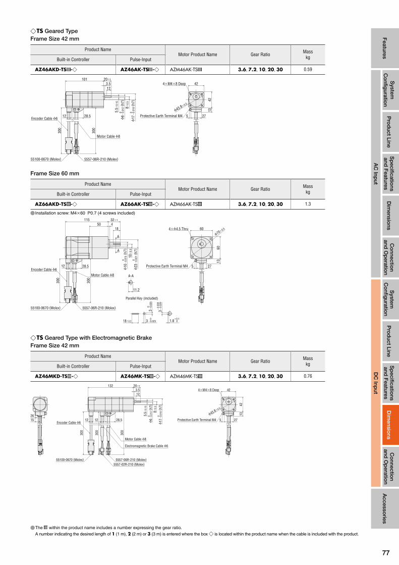
7777
Features
System
C
onfig
uration
Pro
duct Line
Sp
ecifications
and F
eaturesD
imensio
nsC
onnectio
n and
Op
eration
Accesso
ries
AC
Input
System
C
onfig
uration
Pro
duct Line
Sp
ecifications
and F
eaturesC
onnectio
n and
Op
eration
Dim
ensions
DC
Input
◇TS Geared TypeFrame Size 42 mm
Product NameMotor Product Name Gear Ratio Mass
kgBuilt-in Controller Pulse-Input
AZ46AKD-TS ■ -◇ AZ46AK-TS ■ -◇ AZM46AK-TS ■ 3.6, 7.2, 10, 20, 30 0.59
42
4213ϕ43.8±0.5
5.5±
0.15
8±0.
5
ϕ6−
0.01
2 (h7
)0
ϕ17
−0.
018 (
h7)
0
28.5
300
12
300
5557-06R-210 (Molex)55100-0670 (Molex)
101 20±1
3.512
275
4×M4×8 Deep
Encoder Cable ϕ6
Motor Cable ϕ8
Protective Earth Terminal M4
Frame Size 60 mm
Product NameMotor Product Name Gear Ratio Mass
kgBuilt-in Controller Pulse-Input
AZ66AKD-TS ■ -◇ AZ66AK-TS ■ -◇ AZM66AK-TS ■ 3.6, 7.2, 10, 20, 30 1.3
● Installation screw: M4×60 P0.7 (4 screws included)
ϕ70±0.560
6013
ϕ23
−0.
021 (
h7)
010
±0.
5
ϕ10
−0.
015 (
h7)
0
11550
32±1
184
28.512
300
300
5557-06R-210 (Molex)55100-0670 (Molex)
A
A
275
4×ϕ4.5 Thru
Motor Cable ϕ8Encoder Cable ϕ6
A-A
11.2
18±0.2
3−0.
029
−0.
004
1.8+0.1 03−0.025
0
03−
0.02
5
Parallel Key (included)
Protective Earth Terminal M4
◇TS Geared Type with Electromagnetic BrakeFrame Size 42 mm
Product NameMotor Product Name Gear Ratio Mass
kgBuilt-in Controller Pulse-Input
AZ46MKD-TS ■ -◇ AZ46MK-TS ■ -◇ AZM46MK-TS ■ 3.6, 7.2, 10, 20, 30 0.76
42
4213ϕ43.8±0.5
2751526 5.
5±0.
15
8±0.
5
ϕ6−
0.01
2 (h7
)0
ϕ17
−0.
018 (
h7)
0
132 20±1
3.512
5557-06R-210 (Molex)55100-0670 (Molex)5557-02R-210 (Molex)
300
300
300
28.51212
4×M4×8 Deep
Protective Earth Terminal M4
Motor Cable ϕ8
Electromagnetic Brake Cable ϕ6
Encoder Cable ϕ6
●The ■ within the product name includes a number expressing the gear ratio.
A number indicating the desired length of 1 (1 m), 2 (2 m) or 3 (3 m) is entered where the box ◇ is located within the product name when the cable is included with the product.

7878
Frame Size 60 mm
Product NameMotor Product Name Gear Ratio Mass
kgBuilt-in Controller Pulse-Input
AZ66MKD-TS ■ -◇ AZ66MK-TS ■ -◇ AZM66MK-TS ■ 3.6, 7.2, 10, 20, 30 1.7
● Installation screw: M4×60 P0.7 (4 screws included)
18
12 12 28.5
300
300
300
450161
60
601326
15.5
A
A
5557-06R-210 (Molex)5557-02R-210 (Molex)
55100-0670 (Molex)
ϕ23
−0.
021 (
h7)
010
±0.
5
ϕ10
−0.
015 (
h7)
0
32±1
ϕ70±0.5
275
11.2
A-A
Motor Cable ϕ8
18±0.2
3−0.
029
−0.
004
1.8+0.1 03−0.025
0
03−
0.02
5
Parallel Key (included)
Protective Earth Terminal M4
4×ϕ4.5 Thru
Electromagnetic Brake Cable ϕ6
Encoder Cable ϕ6
◇PS Geared TypeFrame Size 42 mm
Product NameMotor Product Name Gear Ratio L Mass
kgBuilt-in Controller Pulse-Input
AZ46AKD-PS ■ -◇ AZ46AK-PS ■ -◇ AZM46AK-PS ■ 5, 7.2, 10 98 0.64
25, 36, 50 121.5 0.79
ϕ43.8±0.5
42
4213
L 28±1
10 15
A
A
ϕ10
−0.
015 (
h7)
ϕ26
−0.
021 (
h7)
00
11.2
15±0.2 3−0.0250
1.8+0.1 0
03−
0.02
5
A-A
3−0.
029
−0.
004
28.5
300
12
300
5557-06R-210 (Molex)55100-0670 (Molex)
275
4×M4×8 Deep
Parallel Key (included)
Encoder Cable ϕ6
Motor Cable ϕ8
Protective Earth Terminal M4
Frame Size 60 mm
Product NameMotor Product Name Gear Ratio L Mass
kgBuilt-in Controller Pulse-Input
AZ66AKD-PS ■ -◇ AZ66AK-PS ■ -◇ AZM66AK-PS ■ 5, 7.2, 10 104 1.3
25, 36, 50 124 1.6
ϕ70±0.560
6013
28.512
5557-06R-210 (Molex)55100-0670 (Molex)
300
300
L 38±1
2510
0ϕ
12−
0.01
8 (h7
)
ϕ37
−0.
025 (
h7)
0
A
A
275
4×M5×10 Deep
Motor Cable ϕ8Encoder Cable ϕ6
25±0.2 4−0.030
04−
0.03
04−
0.03
2.5 0+0.1
A-A
13.5
Parallel Key (included)
Protective Earth Terminal M4
●The ■ within the product name includes a number expressing the gear ratio.
A number indicating the desired length of 1 (1 m), 2 (2 m) or 3 (3 m) is entered where the box ◇ is located within the product name when the cable is included with the product.

7979
Features
System
C
onfig
uration
Pro
duct Line
Sp
ecifications
and F
eaturesD
imensio
nsC
onnectio
n and
Op
eration
Accesso
ries
AC
Input
System
C
onfig
uration
Pro
duct Line
Sp
ecifications
and F
eaturesC
onnectio
n and
Op
eration
Dim
ensions
DC
Input
◇PS Geared Type with Electromagnetic BrakeFrame Size 42 mm
Product NameMotor Product Name Gear Ratio L Mass
kgBuilt-in Controller Pulse-Input
AZ46MKD-PS ■ -◇ AZ46MK-PS ■ -◇ AZM46MK-PS ■ 5, 7.2, 10 129 0.81
25, 36, 50 152 0.96
42
4213ϕ43.8±0.5
2751526
L 28±1
10 15
ϕ10
−0.
015 (
h7)
ϕ26
−0.
021 (
h7)
00
A
A
5557-06R-210 (Molex)55100-0670 (Molex)5557-02R-210 (Molex)
300
300
300
28.51212
11.2
A-A
4×M4×8 Deep
Protective Earth Terminal M4Encoder Cable ϕ6
Motor Cable ϕ8
Electromagnetic Brake Cable ϕ6
15±0.2 3−0.0250
1.8+0.1 0
03−
0.02
5
3−0.
029
−0.
004
Parallel Key (included)
Frame Size 60 mm
Product NameMotor Product Name Gear Ratio L Mass
kgBuilt-in Controller Pulse-Input
AZ66MKD-PS ■ -◇ AZ66MK-PS ■ -◇ AZM66MK-PS ■ 5, 7.2, 10 150 1.7
25, 36, 50 170 2.0
25
12 12 28.5
300
300
300
10L
27
60
6013
52615.5
A
A
13.5
A-A
0ϕ
12−
0.01
8 (h7
)
ϕ70±0.5
5557-06R-210 (Molex)5557-02R-210 (Molex)
55100-0670 (Molex)
38±1
ϕ37
−0.
025 (
h7)
0
25±0.2 4−0.030
04−
0.03
04−
0.03
2.5 0+0.1
Parallel Key (included)
4×M5×10 Deep
Protective Earth Terminal M4
Motor Cable ϕ8
Electromagnetic Brake Cable ϕ6
Encoder Cable ϕ6
◇HPG Geared Type Shaft Output TypeFrame Size 40 mm
Product NameMotor Product Name Gear Ratio Mass
kgBuilt-in Controller Pulse-Input
AZ46AKD-HP ■ -◇ AZ46AK-HP ■ -◇ AZM46AK-HP ■ 5, 9 0.71
40
40
ϕ46±0.3
28.5
300
12
300
5557-06R-210 (Molex)55100-0670 (Molex)
42
104.5 42±1
5 2215
11.5
4213
2.2 15A
A
0ϕ
10−
0.01
5 (h7
)
ϕ40
−0.
025 (
h7)
0ϕ
39.5
ϕ29
A-A
275
M3×6 Deep4×ϕ3.4 Thru
Encoder Cable ϕ6
Motor Cable ϕ8
2.5+0.1 0
4−0.
030
0
4−0.0300
4−0.
030
0
15−0.180
1.6
90˚
Parallel Key (included)
Protective Earth Terminal M4
●The ■ within the product name includes a number expressing the gear ratio.
A number indicating the desired length of 1 (1 m), 2 (2 m) or 3 (3 m) is entered where the box ◇ is located within the product name when the cable is included with the product.

8080
Frame Size 60 mm
Product NameMotor Product Name Gear Ratio Mass
kgBuilt-in Controller Pulse-Input
AZ66AKD-HP ■ -◇ AZ66AK-HP ■ -◇ AZM66AK-HP ■ 5, 15 1.9
ϕ70±0.360
6013
132 58±1
8 30212.5 25
0ϕ
16−
0.01
8 (h7
)
12
300
300
5557-06R-210 (Molex)55100-0670 (Molex)
A
A
ϕ40
ϕ20
ϕ55
.5ϕ
56−
0.03
0 (h7
)0
27528.5
4×ϕ5.5 Thru
M4×8 Deep
Encoder Cable ϕ6Motor Cable ϕ8
A-A
18
25−0.210
2 90˚
5−0.0300
5−0.
030
0
3+0.1 0
5−0.
030
0
Parallel Key (included)
Protective Earth Terminal M4
◇HPG Geared Type Flange Output TypeFrame Size 40 mm
Product NameMotor Product Name Gear Ratio Mass
kgBuilt-in Controller Pulse-Input
AZ46AKD-HP ■ F-◇ AZ46AK-HP ■ F-◇ AZM46AK-HP ■ F 5, 9 0.66
15−0.20+0.25
2.2
28.5
300
12
300
5557-06R-210 (Molex)55100-0670 (Molex)
42
4213
104.5
3
ϕ5
0
( H
7)+
0.01
2
ϕ24
ϕ39
.5ϕ
40−
0.02
5 (h7
)0
C
5
40
40ϕ18
ϕ46±0.3
120˚
275
4×ϕ3.4 Thru
3×M4×6 Deep
Encoder Cable ϕ6
Motor Cable ϕ8 ϕ24
0.4−0.20 Customer Parts
0.5 or more
C Section Details
Protective Earth Terminal M4
Frame Size 60 mm
Product NameMotor Product Name Gear Ratio Mass
kgBuilt-in Controller Pulse-Input
AZ66AKD-HP ■ F-◇ AZ66AK-HP ■ F-◇ AZM66AK-HP ■ F 5, 15 1.8
ϕ70±0.3
60ϕ30
6013
60˚
ϕ14
0
( H7)
+0.
018
ϕ40
ϕ55
.5ϕ
56−
0.03
0 (h7
)0
132 21−0.5+0.4
85
2.5
12
300
300
5557-06R-210 (Molex)55100-0670 (Molex)
27528.5
4×ϕ5.5 Thru
6×M4×7 Deep
Encoder Cable ϕ6Motor Cable ϕ8
Protective Earth Terminal M4
●The coloured part of the outline drawing is the rotation section. ●The ■ within the product name includes a number expressing the gear ratio.
A number indicating the desired length of 1 (1 m), 2 (2 m) or 3 (3 m) is entered where the box ◇ is located within the product name when the cable is included with the product.

8181
Features
System
C
onfig
uration
Pro
duct Line
Sp
ecifications
and F
eaturesD
imensio
nsC
onnectio
n and
Op
eration
Accesso
ries
AC
Input
System
C
onfig
uration
Pro
duct Line
Sp
ecifications
and F
eaturesC
onnectio
n and
Op
eration
Dim
ensions
DC
Input
◇HPG Geared Type with Electromagnetic Brake Shaft Output TypeFrame Size 40 mm
Product NameMotor Product Name Gear Ratio Mass
kgBuilt-in Controller Pulse-Input
AZ46MKD-HP ■ -◇ AZ46MK-HP ■ -◇ AZM46MK-HP ■ 5, 9 0.88
40
40
ϕ46±0.3
135.5 42±1
5 2215
2.2 15A
A
0ϕ
10−
0.01
5 (h7
)
ϕ40
−0.
025 (
h7)
0ϕ
39.5
ϕ29
1526
5557-06R-210 (Molex)55100-0670 (Molex)5557-02R-210 (Molex)
300
300
300
28.51212
11.5
A-A
2.5+0.1 0
4−0.
030
0
42
4213
275
M3×6 Deep4×ϕ3.4 Thru
Encoder Cable ϕ6
Motor Cable ϕ8
Electromagnetic Brake Cable ϕ6
4−0.0300
4−0.
030
0
15−0.180
1.6
90˚
Parallel Key (included)
Protective Earth Terminal M4
Frame Size 60 mm
Product NameMotor Product Name Gear Ratio Mass
kgBuilt-in Controller Pulse-Input
AZ66MKD-HP ■ -◇ AZ66MK-HP ■ -◇ AZM66MK-HP ■ 5, 15 2.3
15.5
26
178 58±1
8 3021
2.5 25
A
A
300
300
300
28.512
12
5557-06R-210 (Molex)55100-0670 (Molex)
5557-02R-210 (Molex)
0ϕ
16−
0.01
8 (h7
)
ϕ56
−0.
030 (
h7)
0ϕ
55.5
ϕ40
ϕ20 13
60
60
275
18
A-A
ϕ70±0.3
Encoder Cable ϕ6
Motor Cable ϕ8
Electromagnetic Brake Cable ϕ6
Protective Earth Terminal M4
3 0+0.1
5−0.
030
0
5−0.0300
5−0.
030
0
25−0.210
2
90˚
Parallel Key (included)
4×ϕ5.5 Thru
M4×8 Deep
◇HPG Geared Type with Electromagnetic Brake Flange Output TypeFrame Size 40 mm
Product NameMotor Product Name Gear Ratio Mass
kgBuilt-in Controller Pulse-Input
AZ46MKD-HP ■ F-◇ AZ46MK-HP ■ F-◇ AZM46MK-HP ■ F 5, 9 0.83
275
120˚
40
40ϕ18
ϕ46±0.3
15−0.20+0.25
2.2135.5
3
ϕ5
0
( H
7)+
0.01
2
ϕ24
ϕ39
.5ϕ
40−
0.02
5 (h7
)0
5
1526
42
4213
5557-06R-210 (Molex)55100-0670 (Molex)5557-02R-210 (Molex)
300
300
300
28.51212C
ϕ24
0.4−0.20
Protective Earth Terminal M4
4×ϕ3.4 Thru
3×M4×6 Deep
Encoder Cable ϕ6
Motor Cable ϕ8
Electromagnetic Brake Cable ϕ6
Customer Parts
0.5 or more
C Section Details
●The coloured part of the outline drawing is the rotation section. ●The ■ within the product name includes a number expressing the gear ratio.
A number indicating the desired length of 1 (1 m), 2 (2 m) or 3 (3 m) is entered where the box ◇ is located within the product name when the cable is included with the product.

8282
Frame Size 60 mm
Product NameMotor Product Name Gear Ratio Mass
kgBuilt-in Controller Pulse-Input
AZ66MKD-HP ■ F-◇ AZ66MK-HP ■ F-◇ AZM66MK-HP ■ F 5, 15 2.2
ϕ70±0.3
60˚
275
6013
60ϕ30
2615.5
300
300
300
28.512 12
5557-06R-210 (Molex)5557-02R-210 (Molex)
55100-0670 (Molex)
178 21−0.5+0.4
85
2.5
ϕ14
0
( H7)
+0.
018
ϕ40
ϕ55
.5ϕ
56−
0.03
0 (h7
)0
4×ϕ5.5 Thru
6×M4×7 Deep
Protective Earth Terminal M4
Motor Cable ϕ8
Electromagnetic Brake Cable ϕ6
Encoder Cable ϕ6
◇Harmonic Geared TypeFrame Size 42 mm
Product NameMotor Product Name Gear Ratio Mass
kgBuilt-in Controller Pulse-Input
AZ46AKD-HS ■ -◇ AZ46AK-HS ■ -◇ AZM46AK-HS ■ 50, 100 0.65
42
4213
60˚
12
300
55100-0670 (Molex)
0ϕ
10−
0.01
5 (h7
)
ϕ37
.6−
0.02
5 (h7
)0
1022
25±1
0.518
A
A
18−0.180
A-A
11.2
1.2 3−0.0250
1.8+0.1 0
3−0.
025
0
3−0.
029
−0.
004
90˚
ϕ48±0.3ϕ20.5±0.2
27528.5
5557-06R-210 (Molex)
300
4×M4×8 Deep6×M3×5 Deep*
Encoder Cable ϕ6
ϕ26
.5 ( r
otat
ion
part
max
imum
dia
met
er)
Parallel Key (included)
Protective Earth Terminal M4
Motor Cable ϕ8
✽The position of the output shaft relative to the screw holes on the rotating part is arbitrary.
Frame Size 60 mm
Product NameMotor Product Name Gear Ratio Mass
kgBuilt-in Controller Pulse-Input
AZ66AKD-HS ■ -◇ AZ66AK-HS ■ -◇ AZM66AK-HS ■ 50, 100 1.4
ϕ70±0.560
6013
60˚A
A
112 28.5±1
2 1.520
12
300
300
5557-06R-210 (Molex)55100-0670 (Molex)
ϕ54
−0.0
30 ( h
7)00
ϕ15
−0.0
18 ( h
7)
17
A-A
ϕ25.5±0.2
27528.5
4×M5×10 DeepDeep
6×M4×6 Deep*
Motor Cable ϕ8
Encoder Cable ϕ6
ϕ33
.5 ( r
otat
. par
t max
i. di
amet
er)
20−0.210
90˚
2.1
5−0.
030
0
5−0.
030
0
3+0.1 05−0.030
0
Parallel Key (included)
Protective Earth Terminal M4
✽The position of the output shaft relative to the screw holes on the rotating part is arbitrary.
●The coloured part of the outline drawing is the rotation section. ●The ■ within the product name includes a number expressing the gear ratio.
A number indicating the desired length of 1 (1 m), 2 (2 m) or 3 (3 m) is entered where the box ◇ is located within the product name when the cable is included with the product.

8383
Features
System
C
onfig
uration
Pro
duct Line
Sp
ecifications
and F
eaturesD
imensio
nsC
onnectio
n and
Op
eration
Accesso
ries
AC
Input
System
C
onfig
uration
Pro
duct Line
Sp
ecifications
and F
eaturesC
onnectio
n and
Op
eration
Dim
ensions
DC
Input
◇Harmonic Geared Type with Electromagnetic BrakeFrame Size 42 mm
Product NameMotor Product Name Gear Ratio Mass
kgBuilt-in Controller Pulse-Input
AZ46MKD-HS ■ -◇ AZ46MK-HS ■ -◇ AZM46MK-HS ■ 50, 100 0.82
42
4213
60˚
ϕ48±0.3ϕ20.5±0.2
275
133
0ϕ
10−
0.01
5 (h7
)
ϕ37
.6−
0.02
5 (h7
)0
225±1
0.518
A
A
1526
5557-06R-210 (Molex)55100-0670 (Molex)5557-02R-210 (Molex)
300
300
300
28.51212
A-A
11.2
18−0.180
1.2 3−0.0250
1.8+0.1 0
3−0.
025
0
3−0.
029
−0.
004
90˚
4×M4×8 Deep6×M3×5 Deep*
Protective Earth Terminal M4
ϕ26
.5 ( r
otat
. par
t max
i. di
amet
er)
Encoder Cable ϕ6
Motor Cable ϕ8Electromagnetic Brake Cable ϕ6 Parallel Key (included)
✽The position of the output shaft relative to the screw holes on the rotating part is arbitrary.
Frame Size 60 mm
Product NameMotor Product Name Gear Ratio Mass
kgBuilt-in Controller Pulse-Input
AZ66MKD-HS ■ -◇ AZ66MK-HS ■ -◇ AZM66MK-HS ■ 50, 100 1.8
12 28.5
300
300
12
300
201.52
158
27
60
6013
52615.5
A-A
A
A ϕ25.5±0.2
ϕ70±0.5
28.5±1
ϕ54
−0.
030 (
h7)
00ϕ
15−
0.01
8 (h7
)
5557-06R-210 (Molex)5557-02R-210 (Molex)
55100-0670 (Molex)
60˚
4×M5×10 Deep6×M4×6 Deep
Protective Earth Terminal M4
ϕ33
.5 ( r
otat
. par
t max
i. di
amet
er)
Motor Cable ϕ8
Electromagnetic Brake Cable ϕ6
Encoder Cable ϕ6
20−0.210
2.1
5−0.
030
5−0.
030
3 05−0.030
17
90˚
0 0
+0.10
Parallel Key (included)
✽The position of the output shaft relative to the screw holes on the rotating part is arbitrary.
●The coloured part of the outline drawing is the rotation section. ●The ■ within the product name includes a number expressing the gear ratio.
A number indicating the desired length of 1 (1 m), 2 (2 m) or 3 (3 m) is entered where the box ◇ is located within the product name when the cable is included with the product.

8484
●Drivers ◇Built-in Controller Type
Driver Product Name: AZD-KDMass: 0.15kg
35 4
100
35.1
17.5
9.2
4.7
7019.5 max.
Slits ●AccessoriesConnector form in power/electromagnetic brake connections (CN1) Connector: MC1,5/5-STF-3,5 (PHOENIX CONTACT GmbH & Co. KG)
Connector for Input/Output Signal (CN4) Connector: DFMC1,5/12-ST-3,5 (PHOENIX CONTACT GmbH & Co. KG)
◇Pulse-Input TypeDriver Product Name: AZD-KMass: 0.15kg
35 4
100
35.1
17.5
9.2
4.7
7019.5 max.
Slits ●AccessoriesConnector form in power/electromagnetic brake connections (CN1) Connector: MC1,5/5-STF-3,5 (PHOENIX CONTACT GmbH & Co. KG)
Connector for Input/Output Signal (CN4) Connector: DFMC1,5/12-ST-3,5 (PHOENIX CONTACT GmbH & Co. KG)

8585
Features
System
C
onfig
uration
Pro
duct Line
Sp
ecifications
and F
eaturesD
imensio
nsC
onnectio
n and
Op
eration
Accesso
ries
AC
Input
System
C
onfig
uration
Pro
duct Line
Sp
ecifications
and F
eaturesC
onnectio
n and
Op
eration
Dim
ensions
DC
Input
◇Cable for Motor
Cable Type Length L (m)
Cable for Motor 1 m 1
Cable for Motor 2 m 2
Cable for Motor 3 m 3
J11DF-06V-KX(JST)
ϕ6.
4
Driver SideMotor Side
L23.9(12)
( 23)
( 15.
2)
16.7 8
5559-06P-210(Molex)
◇Cable for Encoder
Cable Type Length L (m)
Cable for Encoder 1 m 1
Cable for Encoder 2 m 2
Cable for Encoder 3 m 312.2 12.243.5max.
18.8
18.8
43.5L
ϕ6.5500655-0609(Molex) 500654-0609(Molex)
Motor Side Driver Side
Notes ●The motor cable and the electromagnetic brake cable coming out of the motor cannot be connected directly to the driver. For connection to the driver use the accessory connection cable (sold separately) or the connection cable which is included to the product (for products with included cable).
◇Cable for Electromagnetic Brake (Only for electromagnetic brake products)
Cable Type Length L (m)
Cable for Electromagnetic Brake 1 m 1
Cable for Electromagnetic Brake 2 m 2
Cable for Electromagnetic Brake 3 m 3
23.9L
80ϕ4.
1
(14)
(12)
Motor Side Driver Side
5559-02P-210(Molex)
Stick Terminal: AI0.5-8WH (PHOENIX CONTACT GmbH & Co. KG)
●Cable for Motor (sold separately), Cable for Encoder (sold separately), Cable for Electromagnetic Brake (sold separately)
●Only products with included connection cables
[AZ14, AZ15, AZ24, AZ26 use] ◇Cable for Motor
Cable Type Length L (m)
Cable for Motor 1 m 1
Cable for Motor 2 m 2
Cable for Motor 3 m 3
L9.55 16.7 8
( 15.
2)
43.5 12
18.855100-0670 (Molex)
J11DF-06V-KX (JST)9.3
( 11.
65)
ϕ8
DF62C-13S-2.2C (Hirose Electric Co., Ltd)
Driver SideMotor Side
[AZ46, AZ66, AZ69 use]
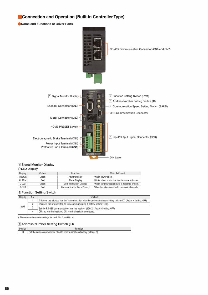
8686
■Connection and Operation (Built-in Controller Type)
●Name and Functions of Driver Parts
3 Address Number Setting Switch (ID)
4 Communication Speed Setting Switch (BAUD)
2 Function Setting Switch (SW1)
HOME PRESET Switch
USB Communication Connector
Protective Earth Terminal (CN1)
RS-485 Communication Connector (CN6 and CN7)
1 Signal Monitor Display
Encoder Connector (CN3)
Motor Connector (CN2)
Electromagnetic Brake Terminal (CN1)
Power Input Terminal (CN1)
5 Input/Output Signal Connector (CN4)
DIN Lever
Signal Monitor Display ◇LED Display
Display Colour Function When ActivatedPOWER Green Power Display When power is on.ALARM Red Alarm Display Blinks when protective functions are activated.C-DAT Green Communication Display When communication data is received or sent.C-ERR Red Communication Error Display When there is an error with communication data.
Function Setting SwitchDisplay No. Function
SW1
1 This sets the address number in combination with the address number setting switch (ID) (Factory Setting: OFF).2 This sets the protocol for RS-485 communication (Factory Setting: OFF).3 Set the RS-485 communication terminal resistor (120Ω) (Factory Setting: OFF).
OFF: no terminal resistor, ON: terminal resistor connected.4
✽Please use the same settings for both No. 3 and No. 4.
Address Number Setting Switch (ID)Display Function
ID Set the address number for RS-485 communication (Factory Setting: 0).

8787
Features
System
C
onfig
uration
Pro
duct Line
Sp
ecifications
and F
eaturesD
imensio
nsC
onnectio
n and
Op
eration
Accesso
ries
AC
Input
System
C
onfig
uration
Pro
duct Line
Sp
ecifications
and F
eaturesD
imensio
nsC
onnectio
n and
Op
eration
DC
Input
Communication Speed Setting SwitchDisplay FunctionBAUD Set this when using RS-485 communications. Set the communication speed (Factory Setting: 7).
◇Settings of the RS-485 Communication Speed
No. Baud Rate (bps)0 96001 192002 384003 576004 1152005 2304006 Not used7 Network Converter
8–F Not used
Input/Output Signal Connector (CN4)
Display Pin Number Signal Name Content
CN4
1 IN0 START This signal is used to start positioning operation.2 IN2 M1 Use the 3 bits of M0, M1, M2, to select the drive data No.3 IN4 ZHOME Move to the home position set with the HOME PRESET switch.4 IN6 STOP Stop the motor.5 IN-COM [0–7]✽1 IN0~IN7 input common6 IN8 FW-JOG Start JOG operation.7 OUT0 HOME-END Output when determining the home position or completing high speed point of return-to-home operation.8 OUT2 PLS-RDY Not used9 OUT4 MOVE Output while operating the motor.
10 OUT-COM✽1 Output common11 ASG+ A phase pulse output+12 BSG+ B phase pulse output+13 IN1 M0 Use the 3 bits of M0, M1, M2, to select the drive data No.14 IN3 M2 Use the 3 bits of M0, M1, M2, to select the drive data No.15 IN5 FREE The motor is set to non-excitation.16 IN7 ALM-RST Reset the alarm.17 IN-COM [8-9]✽1 IN8, IN9 input common18 IN9 RV-JOG Start JOG operation.19 OUT1 IN-POS Output when the motor operation is complete.20 OUT3 READY Output when the driver is ready for operation.21 OUT5 ALM-B Output the driver alarm state (normal close).22 GND✽1 Ground23 ASG− A phase pulse output−24 BSG− B phase pulse output−
●Assigned functions are set by means of the parameter settings. The above is the initial value. For details, refer to the User's Manual. ✽1 The initial value setting cannot be changed.

8888
●Connection Diagram ◇Connection to Peripheral Equipment
PE
AC Power Noise Filter✽2
Use as a countermeasure against noise.This is effective at reducing noise occurring from power or drivers.
Direct current✽2
GND
24 V DC or 48 V DC
Connect to CN2
Cable for Motor✽1
Connect to CN3
Cable for Encoder✽1
Cable for Electromagnetic Brake✽1
Black
White
Connect to MB1 and MB2
Connect to CN6 or CN7✽3
Connect to CN4
Data Setting SoftwareMEXE02
Computer✽2
Controller✽2
This is included in the product.
This is available as an option (sold separately).
Connect to CN1
Connect to USB Communication Connector
✽1 Products with cable for connecting between motor and driver (1 m, 2 m, 3 m) are available as well as those to which such cable is not attached. Cables longer than 3 m or flexible cables can be selected as an option (sold separately). Make sure a cabling distance between the motor and the driver is 20 m or less.
✽2 Prepared by the customer. ✽3 When controlling with RS-485 communications, connect to the controller.
◇USB Cable ConnectionThe computer on which the data setting software MEXE02 is installed and driver are connected with a USB cable.Use the following specifications for the USB cable.
Specification USB2.0 (full speed)
CableLength: 3 m (or less)Format: A-mini-B

8989
Features
System
C
onfig
uration
Pro
duct Line
Sp
ecifications
and F
eaturesD
imensio
nsC
onnectio
n and
Op
eration
Accesso
ries
AC
Input
System
C
onfig
uration
Pro
duct Line
Sp
ecifications
and F
eaturesD
imensio
nsC
onnectio
n and
Op
eration
DC
Input
◇Connecting to a Host Controller ●Connecting to a Current Sink Output Circuit
IN4 (ZHOME)
IN3 (M2)
IN2 (M1)
IN1 (M0)
IN0 (START)
OUT0 (HOME-END)
OUT1 (IN-POS)
OUT2 (PLS-RDY)
OUT3 (READY)
OUT4 (MOVE)
OUT5 (ALM-B)
OUT-COM
IN5 (FREE)
IN6 (STOP)
IN7 (ALM-RST)
IN-COM [0-7]
IN8 (FW-JOG)
IN9 (RV-JOG)
IN-COM [8-9]
ASG-
ASG+
BSG-
BSG+
GND
4.7 kΩ 2.2 kΩ
4.7 kΩ 2.2 kΩ
4.7 kΩ 2.2 kΩ
4.7 kΩ 2.2 kΩ
4.7 kΩ 2.2 kΩ
4.7 kΩ 2.2 kΩ
4.7 kΩ 2.2 kΩ
4.7 kΩ 2.2 kΩ
0 V
0 V
0 V
24 VDC
12~24 VDC
R0
R0
R0
R0
R0
R0
0 V
2.2 kΩ
4.7 kΩ
4.7 kΩ
2.2 kΩ24 VDC
0 V17
18
19
20
21
22
23
24
9
10
11
12
13
14
15
16
8
1
2
3
4
5
6
7
Twisted-pair cable
DriverController
Output SaturationVoltage3 VDC max.
26C31 or equivalent
10 mA or less→
Notes ●For the input signal, use 24 VDC. ●For the output signal, use 12~24 VDC 10 mA or less. Where the current value exceeds 10 mA , connect an external resistor R0 to reduce the current to 10 mA or less. ●Make sure the signal line is wired at a distance of 200 mm or longer from the power lines (power supply line and motor line).
Furthermore, do not insert the signal line in the same pipe as the power lines or bundle them together. ●When noise is emitted from the motor cable or power cable due to wiring or allocation and it cause a problem, use shields or ferrite cores.

9090
◇Connecting to a Host Controller ●Connecting to a Current Source Output Circuit
IN4 (ZHOME)
IN3 (M2)
IN2 (M1)
IN1 (M0)
IN0 (START)
OUT0 (HOME-END)
OUT1 (IN-POS)
OUT2 (PLS-RDY)
OUT3 (READY)
OUT4 (MOVE)
OUT5 (ALM-B)
OUT-COM
IN5 (FREE)
IN6 (STOP)
IN7 (ALM-RST)
IN-COM[0-7]
IN8 (FW-JOG)
IN9 (RV-JOG)
IN-COM[8-9]
ASG-
ASG+
BSG-
BSG+
GND
4.7 kΩ 2.2 kΩ
4.7 kΩ 2.2 kΩ
4.7 kΩ 2.2 kΩ
4.7 kΩ 2.2 kΩ
4.7 kΩ 2.2 kΩ
4.7 kΩ 2.2 kΩ
4.7 kΩ 2.2 kΩ
4.7 kΩ 2.2 kΩ
0 V
0 V
0 V
24 VDC
12∼24 VDC R0
R0
R0
R0
R0
R0
0 V
4.7 kΩ 2.2 kΩ
4.7 kΩ 2.2 kΩ
24 VDC
0 V17
18
19
20
21
22
23
24
9
10
11
12
13
14
15
16
8
1
2
3
4
5
6
7
Twisted-pair cable
DriverController
←10 mA or less
Output SaturationVoltage3 VDC max.
26C31 or equivalent
Notes ●For the input signal, use 24 VDC. ●For the output signal, use 12~24 VDC 10 mA or less. Where the current value exceeds 10 mA , connect an external resistor R0 to reduce the current to 10 mA or less. ●Make sure the signal line is wired at a distance of 200 mm or longer from the power line (power supply line and motor line).
Furthermore, do not insert the signal line in the same pipe as the power lines or bundle them together. ●When noise is emitted from the motor cable or power cable due to wiring or allocation and it cause a problem, use shields or ferrite cores.

9191
Features
System
C
onfig
uration
Pro
duct Line
Sp
ecifications
and F
eaturesD
imensio
nsC
onnectio
n and
Op
eration
Accesso
ries
AC
Input
System
C
onfig
uration
Pro
duct Line
Sp
ecifications
and F
eaturesD
imensio
nsC
onnectio
n and
Op
eration
DC
Input
■Connection and Operation (Pulse-Input Type)
●Names and Functions of Driver Parts
2 Function Setting Switch (SW1)
HOME PRESET Switch
USB Communication Connector
Protective Earth Terminal (CN1)
1 Signal Monitor Display
Motor Connector (CN2)
Electromagnetic Brake Terminal (CN1)
Power Input Terminal (CN1)
5 Input/Output Signal Connector (CN4)
DIN Lever
3 Current Setting Switch (CURRENT)
4 Instruction Filter Setting switch (FIL)Encoder Connector (CN3)
Signal Monitor Display ◇LED Display
Display Colour Function When ActivatedPOWER Green Power Display When power is on.ALARM Red Alarm Display Blinks when protective functions are activated.READY Green READY output When READY output is set to ON
Function Setting SwitchDisplay No. Function
SW1
1 Set the resolution for each motor output axis rotation (Factory Setting : OFF [1000p/r]).
2 Set the pulse input format to 1 pulse input mode or 2 pulse input mode. (Factory Setting: OFF [2 pulse input mode])
3, 4 Not used
Current Setting SwitchDisplay Function
CURRENT Set basic current that is the base for the operation current and stop current (Factory Setting: F).
Command Filter Setting SwitchDisplay Function
FIL Adjust the responsiveness of the motor (Factory Setting: 1).
Input/Output Signal Connector (CN4)
Display Pin Number Signal Name Content
CN4
1 CW+[PLS+]✽1 CW pulse input+[pulse input+]2 CCW+[DIR+]✽1 CCW pulse input+[rotation direction input+]3 IN4 ZHOME Move to the home position set with the HOME PRESET switch.4 IN6 STOP Stop the motor.5 IN-COM [4–7]✽1 IN4–IN7 input common6 IN8 FW-JOG Start JOG operation.
7 OUT0 HOME-END Output when determining the home position or completing high speed home position return operation.
8 OUT2 PLS-RDY Output when the pulse input preparation is complete.9 OUT4 MOVE Output while operating the motor.
10 OUT-COM✽1 Output common11 ASG+ A phase pulse output+12 BSG+ B phase pulse output+13 CW−[PLS−]✽1 CW pulse input−[pulse input−]14 CCW−[DIR−]✽1 CCW pulse input−[rotation direction input−]15 IN5 FREE The motor is set to non-excitation.16 IN7 ALM-RST Reset the alarm.17 IN-COM [8–9]✽1 IN8, IN9 input common18 IN9 RV-JOG Start JOG operation.19 OUT1 IN-POS Output when the motor operation is complete.20 OUT3 READY Outputs when the driver is ready for operation.21 OUT5 ALM-B Output the driver alarm state (normal close).22 GND✽1 Ground23 ASG− A phase pulse output−24 BSG− B phase pulse output−
●Assigned functions are set by means of the parameter settings. The above is the initial value. For details, refer to the User's Manual. ✽1 The initial value setting cannot be changed.

9292
●Connection Diagram ◇Connection to Peripheral Equipment
PE
Connect to CN2
Cable for Motor✽1
Connect to CN3
Cable for Encoder✽1
BlackConnect to MB1 and MB2
AC Power Noise Filter✽2
Use as a countermeasure against noise.This is effective at reducing noise occurring from power or drivers.
Direct current✽2
GND
24 V DCor48 V DC
Cable for Electromagnetic Brake✽1 White
Connect to CN4
Controller✽2
Data Setting SoftwareMEXE02
Computer✽2
Connect to CN1
Connect to USB Communication Connector
This is included in the product.
This is available as an option (sold separately).
✽1 Products with cable for connecting between motor and driver (1 m, 2 m, 3 m) are available as well as those to which such cable is not attached. Cables longer than 3 m or flexible cables can be selected as an option (sold separately). Make sure a cabling distance between the motor and the driver is 20 m or less.
✽2 Prepared by the customer.
◇USB Cable ConnectionThe computer on which the data setting software MEXE02 is installed and driver are connected with a USB cable.Use the following specifications for the USB cable.
Specification USB2.0 (full speed)
CableLength: 3 m (or less)Format: A-mini-B

9393
Features
System
C
onfig
uration
Pro
duct Line
Sp
ecifications
and F
eaturesD
imensio
nsC
onnectio
n and
Op
eration
Accesso
ries
AC
Input
System
C
onfig
uration
Pro
duct Line
Sp
ecifications
and F
eaturesD
imensio
nsC
onnectio
n and
Op
eration
DC
Input
◇Connecting to a Host Controller ●Connecting to a Current Sink Output Circuit
When the pulse input is a line driver
0 V
CW (PLS)+
CW (PLS)-
CCW (DIR)+
IN4 (ZHOME)
OUT0 (HOME-END)
OUT1 (IN-POS)
OUT2 (PLS-RDY)
OUT3 (READY)
OUT4 (MOVE)
OUT5 (ALM-B)
OUT-COM
IN5 (FREE)
IN6 (STOP)
IN7 (ALM-RST)
IN-COM [4-7]
IN8 (FW-JOG)
IN9 (RV-JOG)
IN-COM [8-9]
CCW (DIR)-
ASG-
ASG+
BSG-
BSG+
GND
100 Ω
100 Ω
2.2 kΩ
100 Ω
100 Ω
2.2 kΩ
4.7 kΩ
2.2 kΩ
4.7 kΩ
2.2 kΩ
4.7 kΩ
2.2 kΩ
4.7 kΩ
2.2 kΩ
0 V
0 V
0 V
24 VDC
12~24 VDC
R0
R0
R0
R0
R0
R0
0 V
2.2 kΩ
4.7 kΩ
4.7 kΩ
2.2 kΩ24 VDC
0 V17
18
19
20
21
22
23
24
9
10
11
12
13
14
15
16
8
1
2
3
4
5
6
7
DriverController
10 mA or less→
Output SaturationVoltage3 VDC max.
26C31 or equivalent
Twisted-pair cable
When the pulse input is an open collector
CW(PLS)+
CW(PLS)-
CCW(DIR)+
CCW(DIR)-
100 Ω
100 Ω
2.2 kΩ
100 Ω
100 Ω
R1
R1
2.2 kΩ
5~24 VDC
0 V
13
14
1
2
Driver
Twisted-pair cable
Controller
Notes ●For the input signal, use 24 VDC. ●For the output signal, use 12~24 VDC 10 mA or less. Where the current value exceeds 10 mA , connect an external resistor R0 to reduce the current to 10 mA or less. ●Make sure the signal line is wired at a distance of 200 mm or longer from the power line (power supply line and motor line).Furthermore, do not insert the signal line in the same pipe as the power lines or bundle them together. ●When noise is emitted from the motor cable or power cable due to wiring or allocation and it cause a problem, use shields or ferrite cores.
Notes ●For CW (PLS) input and CCW (DIR) input, use 5~24 VDC. Where the voltage exceeds 5 VDC, connect an external resistor R1 to adjust the input current to be 7~20mA.

9494
◇Connecting to a Host Controller ●Connecting to a Current Source Output Circuit
When the pulse input is a line driver
0 V
CW (PLS)+
CW (PLS)-
CCW (DIR)+
IN4 (ZHOME)
OUT0 (HOME-END)
OUT1 (IN-POS)
OUT2 (PLS-RDY)
OUT3 (READY)
OUT4 (MOVE)
OUT5 (ALM-B)
OUT-COM
IN5 (FREE)
IN6 (STOP)
IN7 (ALM-RST)
IN-COM[4-7]
IN8 (FW-JOG)
IN9 (RV-JOG)
IN-COM[8-9]
CCW (DIR)-
ASG-
ASG+
BSG-
BSG+
GND
100 Ω
100 Ω
2.2 kΩ
100 Ω
100 Ω
2.2 kΩ
4.7 kΩ
2.2 kΩ
4.7 kΩ
2.2 kΩ
4.7 kΩ
2.2 kΩ
4.7 kΩ
2.2 kΩ
0 V
0 V
0 V
24 VDC
12~24 VDC R0
R0
R0
R0
R0
R0
0 V
4.7 kΩ
2.2 kΩ
4.7 kΩ
2.2 kΩ
24 VDC
0 V
13
14
1
2
3
17
18
15
16
4
5
6
19
20
21
22
23
24
9
10
11
12
8
7
DriverController
←10 mA or less
26C31 or equivalent
OutputSaturationVoltage3 VDC max.
Twisted-pair cable
When the pulse input is an open collector
CW(PLS)+
CW(PLS)-
CCW(DIR)+
CCW(DIR)-
100 Ω
100 Ω
2.2 kΩ
100 Ω
100 Ω
R1
R1 2.2 kΩ
5~24 VDC
0 V
13
14
1
2
DriverController
Twisted-pair cable
Notes ●For the input signal, use 24 VDC. ●For the output signal, use 12~24 VDC 10 mA or less. Where the current value exceeds 10 mA, connect to an external resistor R0 to reduce the current to 10 mA or less. ●Make sure the signal line is wired at a distance of 200 mm or longer from the power line (power supply line and motor line).Furthermore, do not insert the signal line in the same pipe as the power lines or bundle them together. ●When noise is emitted from the motor cable or power cable due to wiring or allocation and it cause a problem, use shields or ferrite cores.
Notes ●For CW (PLS) input and CCW (DIR) input, use 5~24 VDC. Where the voltage exceeds 5 VDC, connect an external resistor R1 to adjust the input current to be 7~20mA.

9595
Features
System
C
onfig
uration
Pro
duct Line
Sp
ecifications
and F
eaturesD
imensio
nsC
onnectio
n and
Op
eration
Accesso
ries
AC
Input
System
C
onfig
uration
Pro
duct Line
Sp
ecifications
and F
eaturesD
imensio
nsC
onnectio
n and
Op
eration
DC
Input
■Motor and Driver Combinations
The product names for the motors and drivers comprising a unit are as follows.
●Built-in Controller Type
Type Product Name Motor Product Name Driver Product Name
Standard Type
AZ14AKD-◇ AZM14AK
AZD-KD
AZ15AKD-◇ AZM15AK
AZ24AKD-◇ AZM24AK
AZ26AKD-◇ AZM26AK
AZ46□KD-◇ AZM46□K
AZ66□KD-◇ AZM66□K
AZ69□KD-◇ AZM69□K
TS Geared TypeAZ46□KD-TS ■ -◇ AZM46□K-TS ■
AZ66□KD-TS ■ -◇ AZM66□K-TS ■
PS Geared TypeAZ46□KD-PS ■ -◇ AZM46□K-PS ■
AZ66□KD-PS ■ -◇ AZM66□K-PS ■
HPG Geared Type
AZ46□KD-HP ■ -◇ AZM46□K-HP ■
AZ46□KD-HP ■ F-◇ AZM46□K-HP ■ F
AZ66□KD-HP ■ -◇ AZM66□K-HP ■
AZ66□KD-HP ■ F-◇ AZM66□K-HP ■ F
Harmonic Geared TypeAZ46□KD-HS ■ -◇ AZM46□K-HS ■
AZ66□KD-HS ■ -◇ AZM66□K-HS ■
●Pulse-Input Type
Type Product Name Motor Product Name Driver Product Name
Standard Type
AZ14AK-◇ AZM14AK
AZD-K
AZ15AK-◇ AZM15AK
AZ24AK-◇ AZM24AK
AZ26AK-◇ AZM26AK
AZ46□K-◇ AZM46□K
AZ66□K-◇ AZM66□K
AZ69□K-◇ AZM69□K
TS Geared TypeAZ46□K-TS ■ -◇ AZM46□K-TS ■
AZ66□K-TS ■ -◇ AZM66□K-TS ■
PS Geared TypeAZ46□K-PS ■ -◇ AZM46□K-PS ■
AZ66□K-PS ■ -◇ AZM66□K-PS ■
HPG Geared Type
AZ46□K-HP ■ -◇ AZM46□K-HP ■
AZ46□K-HP ■ F-◇ AZM46□K-HP ■ F
AZ66□K-HP ■ -◇ AZM66□K-HP ■
AZ66□K-HP ■ F-◇ AZM66□K-HP ■ F
Harmonic Geared TypeAZ46□K-HS ■ -◇ AZM46□K-HS ■
AZ66□K-HS ■ -◇ AZM66□K-HS ■
Either A (single shaft) or M (electromagnetic brake) indicating the configuration is entered where the box □ is located within the product name.The ■ within the product name includes a number expressing the gear ratio.
A number indicating the desired length of 1 (1 m), 2 (2 m) or 3 (3 m) is entered where the box ◇ is located within the product name when the cable is included with the product.

9696
Accessories (Sold separately)
Connection Cable Sets, Flexible Connection Cable Sets
Extension Cable Sets, Flexible Extension Cable Sets
In the AZ series, there are products with cable for connecting between motor and driver (1 m, 2 m, 3 m) as well as those to which such cable is not attached.When using the motor and driver more than 3 m apart, choose the connection cable set or extension cable set.The extension cable maximum extension length is 20 m (including attached cable).For the standard motor, the cable for motor cable and the cable for encoder make up the set. Whereas for the magnetic brake-attached motor, the cable for motor, the cable for encoder and the cable for magnetic brake make up the set.If the cable becomes bent, use the flexible connection cable set or flexible extension cable set.
DriverMotor
or
Connection Cable Set/Flexible Connection Cable Set
Extension Cable Set/Flexible Extension Cable Set
Connection Cable (Accessory) length: 1 m, 2 m, 3 m
Notes ●Cables for motor and magnetic brake from the motor cannot be connected directly to the driver. When connecting to the driver, use the optional (sold separately) connection cable or the connection cable attached to the product (only for types with a connection cable attached).
AC Input
Connection Cable Sets, Flexible Connection Cable Sets
■Product Line
●Connection Cable Sets ◇For Standard Motor
Cable for Motor Cable for Encoder
Product Name Length L (m)CC010VZF 1CC020VZF 2CC030VZF 3CC050VZF 5CC070VZF 7CC100VZF 10CC150VZF 15CC200VZF 20
◇For Electromagnetic Brake Motor
Cable for Motor Cable for Encoder Cable for Electromagnetic Brake
Product Name Length L (m)CC010VZFB 1CC020VZFB 2CC030VZFB 3CC050VZFB 5CC070VZFB 7CC100VZFB 10CC150VZFB 15CC200VZFB 20
●Flexible Connection Cable Sets ◇For Standard Motor
Cable for Motor Cable for Encoder
Product Name Length L (m)CC010VZR 1CC020VZR 2CC030VZR 3CC050VZR 5CC070VZR 7CC100VZR 10CC150VZR 15CC200VZR 20
◇For Electromagnetic Brake Motor
Cable for Motor Cable for Encoder Cable for Electromagnetic Brake
Product Name Length L (m)CC010VZRB 1CC020VZRB 2CC030VZRB 3CC050VZRB 5CC070VZRB 7CC100VZRB 10CC150VZRB 15CC200VZRB 20

9797
Features
System
C
onfig
uration
DC
Input
Pro
duct Line
Sp
ecifications
and F
eaturesD
imensio
nsC
onnectio
n and
Op
eration
Accesso
ries
AC
Input
System
C
onfig
uration
Pro
duct Line
Sp
ecifications
and F
eaturesD
imensio
nsC
onnectio
n and
Op
eration
Extension Cable Sets, Flexible Extension Cable Set
■Product Line
●Extension Cable Sets ◇For Standard Motor
Cable for Motor Cable for Encoder
Product Name Length L (m)CC010VZFT 1CC020VZFT 2CC030VZFT 3CC050VZFT 5CC070VZFT 7CC100VZFT 10CC150VZFT 15
◇For Electromagnetic Brake Motor
Cable for Motor Cable for Encoder Cable for Electromagnetic Brake
Product Name Length L (m)CC010VZFBT 1CC020VZFBT 2CC030VZFBT 3CC050VZFBT 5CC070VZFBT 7CC100VZFBT 10CC150VZFBT 15
●Flexible Extension Cable Sets ◇For Standard Motor
Cable for Motor Cable for Encoder
Product Name Length L (m)CC010VZRT 1CC020VZRT 2CC030VZRT 3CC050VZRT 5CC070VZRT 7CC100VZRT 10CC150VZRT 15
◇For Electromagnetic Brake Motor
Cable for Motor Cable for Encoder Cable for Electromagnetic Brake
Product Name Length L (m)CC010VZRBT 1CC020VZRBT 2CC030VZRBT 3CC050VZRBT 5CC070VZRBT 7CC100VZRBT 10CC150VZRBT 15
■Dimensions (Unit = mm)
●Connection Cable ◇Motor Cable
5559-06P-210(Molex)
F32FSS-05V-KX(JST)
( 40)
22.8 7.15
150+20 0
( 23)
(12) 23.9L
ϕ6.4 (flexible cable is ϕ8)
Driver SideMotor Side
Ring crimp terminal with insulation coating(1.25–4)
◇Encoder Cable
12.2 12.243.5max.
18.8
18.8
43.5L
1∼5m : 500655-0609(Molex)7∼20m : 54280-0609(Molex)
1∼5m : 500654-0609(Molex)7∼20m : 55100-0670(Molex)
Driver SideMotor Side
1∼5m : ϕ6.57∼20m : ϕ7(flexible cable is ϕ8)
◇Electromagnetic Brake Cableϕ4.1 (flexible cable is ϕ6)
23.9L
80(14)
( 12)
Motor Side Driver Side
5559-02P-210(Molex)
Stick Terminal:AI0.5-10WH(PHOENIX CONTACT GmbH & Co. KG)
●Extension Cable ◇Motor Cable
19.6L
23.9(12)
13.8
(15)
(23) 5559-06P-210
(Molex)5557-06R-210(Molex)
Motor Side Driver Side
ϕ6.4 (flexible cable is ϕ8)
◇Encoder Cable
12.2 12.243.5max.
18.8
18.8
43.5L
54280-0609(Molex) 55100-0670(Molex)
Driver SideMotor Side
ϕ7(flexible cable is ϕ8)
◇Electromagnetic Brake Cable
23.9L
19.6
(15)
5.4(14)
(Molex)(Molex)5557-02R-2105559-02P-210
(12)
ϕ4.1 (flexible cable is ϕ6)
Motor Side Driver Side
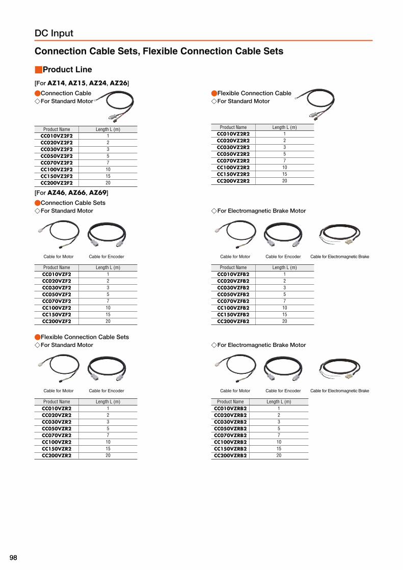
9898
DC Input
Connection Cable Sets, Flexible Connection Cable Sets
■Product Line
[For AZ14, AZ15, AZ24, AZ26]
●Connection Cable ◇For Standard Motor
Product Name Length L (m)CC010VZ2F2 1CC020VZ2F2 2CC030VZ2F2 3CC050VZ2F2 5CC070VZ2F2 7CC100VZ2F2 10CC150VZ2F2 15CC200VZ2F2 20
●Flexible Connection Cable ◇For Standard Motor
Product Name Length L (m)CC010VZ2R2 1CC020VZ2R2 2CC030VZ2R2 3CC050VZ2R2 5CC070VZ2R2 7CC100VZ2R2 10CC150VZ2R2 15CC200VZ2R2 20
[For AZ46, AZ66, AZ69]
●Connection Cable Sets ◇For Standard Motor
Cable for Motor Cable for Encoder
Product Name Length L (m)CC010VZF2 1CC020VZF2 2CC030VZF2 3CC050VZF2 5CC070VZF2 7CC100VZF2 10CC150VZF2 15CC200VZF2 20
◇For Electromagnetic Brake Motor
Cable for Motor Cable for Encoder Cable for Electromagnetic Brake
Product Name Length L (m)CC010VZFB2 1CC020VZFB2 2CC030VZFB2 3CC050VZFB2 5CC070VZFB2 7CC100VZFB2 10CC150VZFB2 15CC200VZFB2 20
●Flexible Connection Cable Sets ◇For Standard Motor
Cable for Motor Cable for Encoder
Product Name Length L (m)CC010VZR2 1CC020VZR2 2CC030VZR2 3CC050VZR2 5CC070VZR2 7CC100VZR2 10CC150VZR2 15CC200VZR2 20
◇For Electromagnetic Brake Motor
Cable for Motor Cable for Encoder Cable for Electromagnetic Brake
Product Name Length L (m)CC010VZRB2 1CC020VZRB2 2CC030VZRB2 3CC050VZRB2 5CC070VZRB2 7CC100VZRB2 10CC150VZRB2 15CC200VZRB2 20

9999
Features
System
C
onfig
uration
DC
Input
Pro
duct Line
Sp
ecifications
and F
eaturesD
imensio
nsC
onnectio
n and
Op
eration
Accesso
ries
AC
Input
System
C
onfig
uration
Pro
duct Line
Sp
ecifications
and F
eaturesD
imensio
nsC
onnectio
n and
Op
eration
Extension Cable Sets, Flexible Extension Cable Sets
■Product Line
[For AZ14, AZ15, AZ24, AZ26]
●Extension Cable ◇For Standard Motor
Product Name Length L (m)CC010VZ2FT 1CC020VZ2FT 2CC030VZ2FT 3CC050VZ2FT 5CC070VZ2FT 7CC100VZ2FT 10CC150VZ2FT 15
●Flexible Extension Cable ◇For Standard Motor
Product Name Length L (m)CC010VZ2RT 1CC020VZ2RT 2CC030VZ2RT 3CC050VZ2RT 5CC070VZ2RT 7CC100VZ2RT 10CC150VZ2RT 15
[For AZ46, AZ66, AZ69]
●Extension Cable Sets ◇For Standard Motor
Cable for Motor Cable for Encoder
Product Name Length L (m)CC010VZFT 1CC020VZFT 2CC030VZFT 3CC050VZFT 5CC070VZFT 7CC100VZFT 10CC150VZFT 15
◇For Electromagnetic Brake Motor
Cable for Motor Cable for Encoder Cable for Electromagnetic Brake
Product Name Length L (m)CC010VZFBT 1CC020VZFBT 2CC030VZFBT 3CC050VZFBT 5CC070VZFBT 7CC100VZFBT 10CC150VZFBT 15
●Flexible Extension Cable Sets ◇For Standard Motor
Cable for Motor Cable for Encoder
Product Name Length L (m)CC010VZRT 1CC020VZRT 2CC030VZRT 3CC050VZRT 5CC070VZRT 7CC100VZRT 10CC150VZRT 15
◇For Electromagnetic Brake Motor
Cable for Motor Cable for Encoder Cable for Electromagnetic Brake
Product Name Length L (m)CC010VZRBT 1CC020VZRBT 2CC030VZRBT 3CC050VZRBT 5CC070VZRBT 7CC100VZRBT 10CC150VZRBT 15
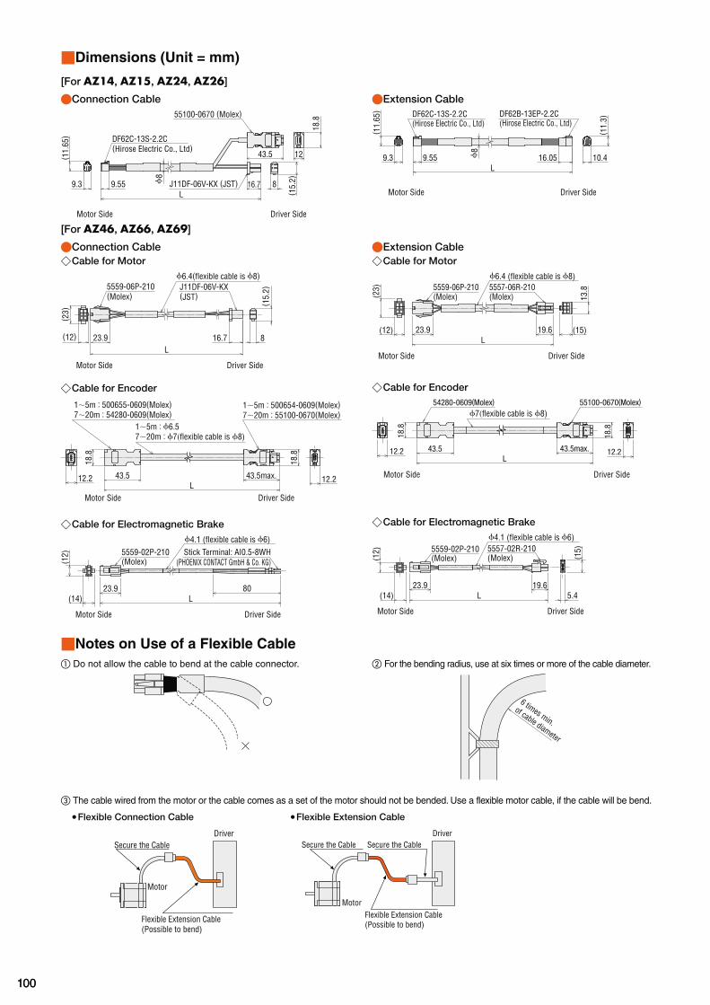
100100
■Dimensions (Unit = mm)
[For AZ14, AZ15, AZ24, AZ26]
●Connection Cable
L9.55 16.7 8
( 15.
2)
43.5 12
18.855100-0670 (Molex)
J11DF-06V-KX (JST)9.3
( 11.
65)
ϕ8
DF62C-13S-2.2C (Hirose Electric Co., Ltd)
Driver SideMotor Side
●Extension Cable
L9.559.3
( 11.
65)
16.05 10.4
( 11.
3)
ϕ8
DF62C-13S-2.2C (Hirose Electric Co., Ltd)
DF62B-13EP-2.2C (Hirose Electric Co., Ltd)
Driver SideMotor Side
[For AZ46, AZ66, AZ69]
●Connection Cable ◇Cable for Motor
ϕ6.4(flexible cable is ϕ8)J11DF-06V-KX(JST)
Driver SideMotor Side
L23.9(12)
( 23)
( 15.
2)
16.7 8
5559-06P-210(Molex)
◇Cable for Encoder
12.2 12.243.5max.
18.8
18.8
43.5L
1∼5m : 500655-0609(Molex)7∼20m : 54280-0609(Molex)
1∼5m : 500654-0609(Molex)7∼20m : 55100-0670(Molex)
Driver SideMotor Side
1∼5m : ϕ6.57∼20m : ϕ7(flexible cable is ϕ8)
◇Cable for Electromagnetic Brake
23.9L
80(14)
(12)
Motor Side Driver Side
5559-02P-210(Molex)
ϕ4.1 (flexible cable is ϕ6)Stick Terminal: AI0.5-8WH
(PHOENIX CONTACT GmbH & Co. KG)
●Extension Cable ◇Cable for Motor
19.6L
23.9(12)
13.8
(15)
(23) 5559-06P-210
(Molex)5557-06R-210(Molex)
Motor Side Driver Side
ϕ6.4 (flexible cable is ϕ8)
◇Cable for Encoder
12.2 12.243.5max.
18.8
18.8
43.5L
54280-0609(Molex) 55100-0670(Molex)
Driver SideMotor Side
ϕ7(flexible cable is ϕ8)
◇Cable for Electromagnetic Brake
23.9L
19.6(1
5)
5.4(14)
(Molex)(Molex)5557-02R-2105559-02P-210
(12)
ϕ4.1 (flexible cable is ϕ6)
Motor Side Driver Side
■Notes on Use of a Flexible Cable
① Do not allow the cable to bend at the cable connector. ② For the bending radius, use at six times or more of the cable diameter.
6 times min.
of cable diameter
③ The cable wired from the motor or the cable comes as a set of the motor should not be bended. Use a flexible motor cable, if the cable will be bend.
●Flexible Connection Cable ●Flexible Extension Cable
DriverSecure the Cable
Motor
Flexible Extension Cable(Possible to bend)
Secure the Cable Secure the Cable
Motor
Driver
Flexible Extension Cable(Possible to bend)

101101
Features
System
C
onfig
uration
DC
Input
Pro
duct Line
Sp
ecifications
and F
eaturesD
imensio
nsC
onnectio
n and
Op
eration
Accesso
ries
AC
Input
System
C
onfig
uration
Pro
duct Line
Sp
ecifications
and F
eaturesD
imensio
nsC
onnectio
n and
Op
eration
Data Setting Software MEXE02From the computer, it is not only possible to set and edit driving data and the various parameters, but also to monitor the waveforms of teaching, I/O and driving speed.The data setting software is available for download from our website.Furthermore, the data setting software is distributed on a CD-ROM.For details, ask from our website or inquire at your nearest branch or sales office.
■Operating Environment
●Computer
Recommended CPU✽1 Intel Core Processor 2 GHz or more(The OS must be supported.)
Displayhigh resolution video adapter and monitor, XGA(1024x768) or more.
Recommended Memory✽1 32 bit (x86) version: 1 GB or more64 bit (x64) version: 2 GB or more
Hard Disk✽2 Available disk space of 60 MB or more
USB Port USB2.0 1 port
Disk Device CD-ROM drive (use for installation of software)
✽1 The OS operating conditions need to be satisfied. ✽2 Microsoft .NET Framework 4 Client Profile is required to use MEXE02. If it
is not already installed, it will be installed automatically, in which case up to 1.5 GB of additional space is required.
●Windows and Windows Vista are registered trademarks of Microsoft Corporation in the United States and other countries. Pentium is a trademark of Intel Corporation. ●Please refer to our website for the latest update of operating environment.
Notes ●The required volume of memory or hard disk may vary depending on the system environment.
●Operating Systems (OS)Both the 32-bit (x86) and 64 bit (x64) editions are supported.
●Microsoft Windows XP Service Pack 3✽
●Microsoft Windows Vista Service Pack 2 ●Microsoft Windows 7 Service Pack 1 ●Microsoft Windows 8 ●Microsoft Windows 8.1 ✽This works with Service Pack 2 when using 64 bit (x64) edition.
■Connection between Computer and Driver
Use the following specifications for the USB cable.
Specification USB2.0 (full speed)
Cable Length: 3 m (or less)Format: A-mini-B
RS-485 Communication Cable The cable is to link drivers when the driver is being operated under multi-axis mode, it also connects the network converter and driver.
■Product Line
Product Name Applicable Product Length L (m)
CC001-RS4 DC Power Supply Input Driver 0.1
CC002-RS4AC Power Supply Input DriverDC Power Supply Input Driver 0.25
■Dimensions (Unit = mm)
L21.7
11.7
ϕ6.2
Generic Cable for Input/Output Signals
This is a convenient multi-core cable for connecting the driver and upper level controller.Choose the necessary cable in accordance with the number of connecting I/O signals.
■Product Line
Lead wire
No. of cores
Cable Length
0.5 m 1 m 1.5 m 2 m
6 CC06D005B-1 CC06D010B-1 CC06D015B-1 CC06D020B-1
10 CC10D005B-1 CC10D010B-1 CC10D015B-1 CC10D020B-1
12 CC12D005B-1 CC12D010B-1 CC12D015B-1 CC12D020B-1
16 CC16D005B-1 CC16D010B-1 CC16D015B-1 CC16D020B-1
■Dimensions (Unit = mm)
300+30 0
3456789
1011121314
3456789
1011121314
1516
21
1516
21
Ring crimp terminal with insulation coating (1.25−4) AWG24, finished diameterϕ1.1
L150 150
ϕ7.
5
7 7
300+30 0
●The outline drawing is of 16 cores.

102102
MCV Couplings
This is a one piece structure coupling with the vibration-proof rubber formed between the aluminium alloy hubs.
■Product Line
Product Name
MCV15□
MCV25□
MCV30□
●A number indicating the coupling inner diameter is entered where the box is located within the product name.
■Product Number Code
MCV 25 10 12① ② ③ ④
① MCV Couplings ●For inner diameter d1, the smaller of the motor shaft diameter or the driven shaft diameter is entered. For inner diameter d2, the larger of the motor shaft diameter or the driven shaft diameter is entered.
② Outer Diameter of Coupling
③Inner Diameter d1 (smaller inner diameter) (06A represents ϕ6.35 mm)
④Inner Diameter d2 (larger inner diameter) (06A represents ϕ6.35 mm)
■Coupling Selection Table
● Coupling is selected based on the following content.· The motor output torque is within the generic torque for coupling.· Motor shaft diameter
Applicable Product
Coupling TypeMotor Shaft
Diametermm
Driven Shaft Diameter mm
Type Frame Size Product Name
03 04 05 06 06A 08 10 12 14 15
ϕ3 ϕ4 ϕ5 ϕ6 ϕ6.35 ϕ8 ϕ10 ϕ12 ϕ14 ϕ15
Standard Type
20 mm AZ14, AZ15
MCV15
04 ϕ4 ● ● ●
28 mm AZ24, AZ26 05 ϕ5 ● ● ● ●
42 mm AZ46 06 ϕ6 ● ● ●
60 mm AZ66, AZ69 MCV25 10 ϕ10 ● ● ● ● ●
85 mm AZ98, AZ911 MCV30 14 ϕ14 ● ● ● ● ●
●The applicable product name includes the characters that can distinguish the product name.
②25
③10
④12

103103
Features
System
C
onfig
uration
DC
Input
Pro
duct Line
Sp
ecifications
and F
eaturesD
imensio
nsC
onnectio
n and
Op
eration
Accesso
ries
AC
Input
System
C
onfig
uration
Pro
duct Line
Sp
ecifications
and F
eaturesD
imensio
nsC
onnectio
n and
Op
eration
MCS Couplings
This is a three piece structure coupling comprised of aluminium alloy hubs and resin spiders.
■Product Line
Product Name
MCS20□
MCS30□
MCS40□
MCS55□
MCS65□
●A number indicating the coupling inner diameter is entered where
the box □ is located within the product name.
■Product Number Code
MCS 30 10 12① ② ③ ④
① MCS Couplings ●For inner diameter d1, the smaller of the motor shaft diameter or the driven shaft diameter is entered. For inner diameter d2, the larger of the motor shaft diameter or the driven shaft diameter is entered.
② Outer Diameter of Coupling
③Inner Diameter d1 (smaller inner diameter) (F04 represents ϕ6.35 mm)
④Inner Diameter d2 (larger inner diameter) (F04 represents ϕ6.35 mm)
■Coupling Selection Table
● Coupling is selected based on the following content.· The motor output torque is within the generic torque for coupling.· Motor shaft diameter ● When using the parallel key, choose an appropriate coupling for the parallel key.
Applicable Product
Gear Ratio Coupling Type
Motor ShaftDiameter
mm
Driven Shaft Diameter mm
Type Frame Size Product Name05 06 F04 08 10 12 14 15 16 18 20 22 24 25
ϕ5 ϕ6 ϕ6.35 ϕ8 ϕ10 ϕ12 ϕ14 ϕ15 ϕ16 ϕ18 ϕ20 ϕ22 ϕ24 ϕ25
TS Geared Type
42 mm AZ46-TS□3.6, 7.2 MCS20
06 ϕ6● ● ● ● ●
10, 20, 30 MCS30 ● ● ● ● ● ● ● ●
60 mm AZ66-TS□3.6, 7.2 MCS30
10 ϕ10● ● ● ● ● ● ● ●
10, 20, 30 MCS40 ● ● ● ● ● ● ● ●
90 mm AZ98-TS□3.6, 7.2, 10 MCS55
18 ϕ18● ● ● ● ● ● ● ●
20, 30 MCS65 ● ● ● ● ● ●
PS Geared Type
42 mm AZ46-PS□5 MCS20
10 ϕ10● ● ● ● ●
7.2, 10, 25, 36, 50 MCS30 ● ● ● ● ● ● ● ●
60 mm AZ66-PS□5, 7.2 MCS40
12 ϕ12● ● ● ● ● ● ● ●
10, 25, 36, 50 MCS55 ● ● ● ● ● ● ● ●
90 mm AZ98-PS□5, 7.2 MCS55
18 ϕ18● ● ● ● ● ● ● ●
10, 25, 36, 50 MCS65 ● ● ● ● ● ●
HPG Geared Type
40 mm AZ46-HP□ 5, 9 MCS30 10 ϕ10 ● ● ● ● ● ● ● ●
60 mm AZ66-HP□ 5, 15 MCS55 16 ϕ16 ● ● ●
90 mm AZ98-HP□ 5, 15 MCS65 25 ϕ25 ● ●
Harmonic Geared Type
42 mm AZ46-HS□ 50, 100 MCS40 10 ϕ10 ● ● ● ● ● ● ● ●
60 mm AZ66-HS□ 50, 100 MCS55 15 ϕ15 ● ● ●
●The applicable product name includes the characters that can distinguish the product name. ●The □ within the product name includes a number expressing the reduction ratio.
④12
③10
② 3
0

104104
Motor Mounting Brackets
Mounting brackets are convenient for installation and securing a stepping motor and geared stepping motor. The attachment fitting fixing section is a convenient long hole specification for adjusting belt tension after assembling the motor.
■Motor Mounting Direction
The motor cable comes out at right angles to the motor. Orient the motor so that the cable faces either upward or sideways.
● For PLA60G, PLA90G, PLA60H, PLA90H: The cable can face downward.
Cable facing upward Cable facing sideways
■How to mount the motor
PAL2P-5, SOL2M4 PAL4P-5, SOL5M8
PAL0P, SOL0B PAF0P, PFB28A PLA60G, PLA60H PLA90G, PLA90H
B BB
A
B
*
**
*
① Use the screws provided to secure the motor to the mounting bracket.
② Attach the motor from the direction shown by the arrow (B).
① Use the screws provided to secure the motor to the mounting bracket.
② Attach the motor from the direction shown by the arrow (B).
① Use the screws provided to secure the motor to the mounting bracket.
② Attach moto r f rom the direction shown by either arrow (A) or arrow (B).
① Use the screw to attach the motor to the attachment fitting.
② Attach the motor from the direction shown by the arrow (B).
* Motor mounting hole on PLA90H is processed with tapping. Insert the screw from direction B.
■Product Line
●Standard TypeMaterial: Aluminum Alloy (SPCC)✽
Surface processing: paint (electroless nickel plating)✽
Product Name Motor Frame Size Applicable Product
PFB28A 28 mm AZ24, AZ26PAF0P
42 mm AZ46PAL0PPAL2P-5 60 mm AZ66, AZ69PAL4P-5 85 mm AZ98 ✽The PFB28A specification is indicated within ( ). ●These mounting brackets can be perfectly fitted to the pilot of the stepping motors. (Except for PAL0P) ●There is a motor attachment screw attached.
●TS Geared TypeMaterial: Aluminum AlloySurface processing: painting
Product Name Motor Frame Size Applicable Product
SOL0B 42 mm AZ46SOL2M4 60 mm AZ66SOL5M8 90 mm AZ98
●PS Geared TypeMaterial: SS400Surface processing: electroless nickel plating
Product Name Motor Frame Size Applicable Product
PLA60G 60 mm AZ66
PLA90G 90 mm AZ98
●There is a motor attachment screw attached.
●Harmonic Geared TypeMaterial: SS400Surface processing: electroless nickel plating
Product Name Motor Frame Size Applicable Product
PLA60H 60 mm AZ66PLA90H 90 mm AZ98
●There is a motor attachment screw attached.

105105
Features
System
C
onfig
uration
DC
Input
Pro
duct Line
Sp
ecifications
and F
eaturesD
imensio
nsC
onnectio
n and
Op
eration
Accesso
ries
AC
Input
System
C
onfig
uration
Pro
duct Line
Sp
ecifications
and F
eaturesD
imensio
nsC
onnectio
n and
Op
eration
■Dimensions (Unit = mm)
PFB28AMass: 25 g
21
4×ϕ3 23
234 35 49
.5
29
24
2.6
5.53.
5
●Mounting Screws: M2.5 Length 5 mm Included 4 pieces
PAF0PMass: 30 g
A
AA−A
4×ϕ3.5 Thru
42
37
0.5
731±0.3
5466
31
8
3.5
1212 42
ϕ22
0+0.
5
●Mounting Screws: M3 Length 7 mm Included 4 pieces
PAL0PMass: 35 g
31±0.34×ϕ3.5 Thru
23
8
23 153.5 5.5
453 2
42
60
6
50 31±
0.3
2448
29±
0.3
37.6 0 +0.5
R12
●Mounting Screws: M3 Length 10 mm Included 4 pieces
PAL2P-5Mass: 110 g
4 2
1
6
68
4.4
11
2025
R15
6.5
1.5
55
4×M4
7.5
40±
0.3 70
32
83
6250±0.3
50±
0.3
3.5
ϕ36
+0.
1+
0.3
●Mounting Screws: M4 Length 12 mm Included 4 pieces
PAL4P-5Mass: 250 g
9
4×M5
R24
13.66.6
35 30
1 6
2
8050
112
10 56± 0
.3
99
70±0.3
86
70± 0
.3
3
93
5 8
60+0.1 +0.3
●Mounting Screws: M5 Length 16 mm Included 4 pieces
SOL0BMass: 85 g
206
ϕ36
4088
56
94.
4
7.4
1
44
18
4162
40±
0.5
4×ϕ4.5 Thru
7220
2014
2143
.8±
0.3

106106
PLA60GMass: 0.7 kg
5
12
50
1517
4×M5
61
5.5
8.5
25 30
2048
62
70
ϕ9.
5
ϕ5.
8106
10
37.5±0.1
31±0.1
75±
0.1
●Mounting Screws: M5 Length 15 mm Included 4 pieces
PLA60HMass: 0.7 kg
70
ϕ9.
5
ϕ5.
8
5
12
50
10
1517
4×M5
61
5.5
8.5
25 30
2048
62
106
54.5±0.1
31±0.1
75±
0.1
●Mounting Screws: M5 Length 15 mm Included 4 pieces
SOL2M4Mass: 135 g
2263
ϕ54
ϕ50
50108
5.4
2515
8.4
91
18
5482
50±
0.5
4×M4
9330
7862
3170
±0.
3
SOL5M8Mass: 270 g
2693
ϕ83
ϕ80
65146
92
116.
4
9.4
1.5
112
19
73.5
112
66±
0.5
4×M8
12850
4017
104±
0.3
43
PLA90GMass: 1.6 kg
ϕ14ϕ
9
104
65
14
24
3521
.514
6
92
36
8.2
30 6.5 10.5
91
74
14
4×M6
61.5±0.1
46±0.1
100±
0.1
●Mounting Screws: M8 Length 20 mm Included 4 pieces
PLA90HMass: 1.6 kg
4×M8
65
10483.5±0.1
14
24
3521
.5
46±0.1
146
92
36
30 6.5 10.5
91
74
100±
0.1
14
4×M6
●Mounting Screws: M8 Length 30 mm Included 4 pieces, 4 washers
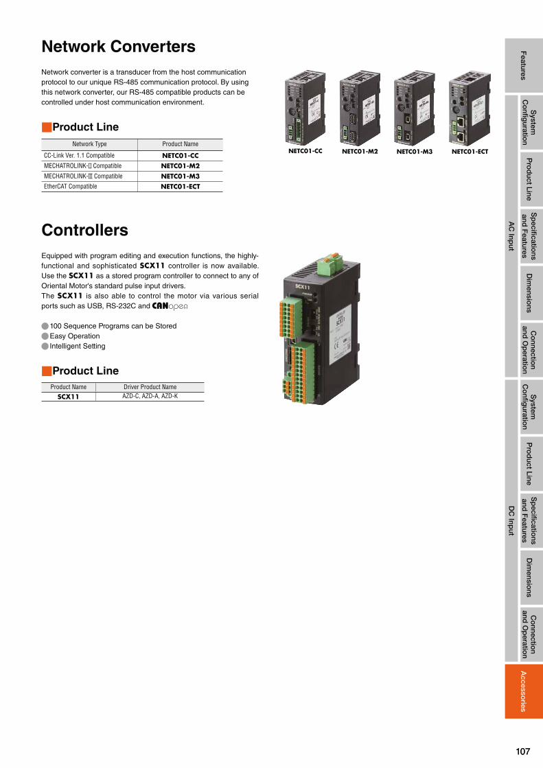
107107
Features
System
C
onfig
uration
DC
Input
Pro
duct Line
Sp
ecifications
and F
eaturesD
imensio
nsC
onnectio
n and
Op
eration
Accesso
ries
AC
Input
System
C
onfig
uration
Pro
duct Line
Sp
ecifications
and F
eaturesD
imensio
nsC
onnectio
n and
Op
eration
Network Converters
Network converter is a transducer from the host communicationprotocol to our unique RS-485 communication protocol. By usingthis network converter, our RS-485 compatible products can becontrolled under host communication environment.
■Product Line
Network Type Product Name
CC-Link Ver. 1.1 Compatible NETC01-CCMECHATROLINK- Compatible NETC01-M2MECHATROLINK- Compatible NETC01-M3EtherCAT Compatible NETC01-ECT
NETC01-CC NETC01-M2 NETC01-M3 NETC01-ECT
Controllers
Equipped with program editing and execution functions, the highly-functional and sophisticated SCX11 controller is now available. Use the SCX11 as a stored program controller to connect to any of Oriental Motor's standard pulse input drivers.The SCX11 is also able to control the motor via various serial ports such as USB, RS-232C and
● 100 Sequence Programs can be Stored ● Easy Operation ● Intelligent Setting
■Product Line
Product Name Driver Product Name
SCX11 AZD-C, AZD-A, AZD-K

These products are manufactured at plants certified with theinternational standards ISO 9001 (for quality assurance) andISO 14001 (for systems of environmental management).
ORIENTAL MOTOR (EUROPA) GmbH
European Headquarters UK Headquarters
Schiessstraße 7440549 Düsseldorf, GermanyTel: 0211-5206700 Fax: 0211-52067099
ORIENTAL MOTOR (UK) LTD.
Unit 5, Faraday Office Park,Rankine Road, Basingstoke,Hampshire RG24 8AH, U.K.Tel: 01256-347090 Fax: 01256-347099
ORIENTAL MOTOR (FRANCE) SARL
France Headquarters
56, Rue des Hautes Pâtures92000 Nanterre Cedex, FranceTel: 01 47 86 97 50 Fax: 01 47 82 45 16
For more information please contact:
www.orientalmotor.de www.oriental-motor.co.uk
www.orientalmotor.fr
Printed in Germany
Customer Center (Support in German & English)
00800 -22 55 66 22
Mon-Thu: 08:00 - 17:30 CET Friday: 08:00 - 16:00 CET
* Free Call Europe
*
CA L L OM CC
ORIENTAL MOTOR ITALIA s.r.l.
Italy Headquarters
Via A. De Gasperi, 8520017 Mazzo di Rho (MI), ItalyTel: 02-93906346 Fax: 02-93906348
ORIENTAL MOTOR CO., LTD.
Headquarters
4-8-1 HigashiuenoTaito-ku, Tokyo 110-8536, JapanTel: (03)6744 -0361 Fax: (03)5826-2576
www.orientalmotor.it
www.orientalmotor.co.jpOther countries:
www.orientalmotor.eu
© Copyright Oriental Motor (Europa) GmbH 2015UK/112015/VERS01
Specifications are subject to change without notice.
This catalogue was published in November 2015.