EQUIPMENT SPECIFICATION APPROVAL/REVISION … · The acceptance criteria for the visually inspected...
17
NCSX-CSPEC-121-001-DraftA National Compact Stellarator Experiment NCSX Product Specification for Vacuum Vessel Assembly (WBS 121) Approved by: ________________________________________ Date ___________________ G. H. Neilson; NCSX Project Manager
Transcript of EQUIPMENT SPECIFICATION APPROVAL/REVISION … · The acceptance criteria for the visually inspected...
NCSX-CSPEC-121-001-DraftA
National Compact Stellarator Experiment
NCSX
Product Specification
for
Vacuum Vessel Assembly (WBS 121)
Approved by: ________________________________________ Date ___________________
G. H. Neilson; NCSX Project Manager

NCSX-CSPEC-121-001-DraftA PAGE 2 OF 17
TABLE OF CONTENTS SECTION PAGE 1.0 SCOPE ............................................................................................................................... 3 2.0 APPLICABLE DOCUMENTS...................................…………………….........…....…... 3 3.0 VACUUM VESSEL REQUIREMENTS........................................................................... 4 3.1 VACUUM VESSEL CONFIGURATION ............................................................. 5
3.2 MATERIALS ......................................................................................................... 5
3.3 WELDING.............................................................................................................. 6
3.4 PERFORMANCE REQUIREMENTS................................................................... 6
3.5 SURFACE QUALITY AND PREPARATION...................................................... 7
3.6 PORTS.................................................................................................................... 7
3.7 DIMENSIONS/TOLERANCES............................................................................. 8
3.8 FABRICATION...................................................................................................... 9
3.9 FASTENERS.......................................................................................................... 11
3.10 SEALS .................................................................................................................... 12
3.11 CLEANING............................................................................................................ 12
3.12 PERMEABILITY ................................................................................................... 12
3.13 INSTALLATION ................................................................................................... 12
3.14 DELIVERABLES................................................................................................... 12
4.0 QUALITY ASSURANCE REQUIREMENTS.................................................................. 13 5.0 PREPARATION FOR DELIVERY................................................................................... 16 6.0 MANUFACTURER’S DATA ........................................................................................... 17 ATTACHMENTS 1. DS PEX00003-A01-1 Offer Appraisal Data 2. DS PEX00003-A01-2 Advanced Engineering Data 3. DS PEX00003-A01-3 Design Approval Data 4. DS PEX00003-A01-4 Certified Data
NCSX-CSPEC-121-001-DraftA PAGE 3 OF 17
1.0 SCOPE
This specification covers the fabrication of the vacuum vessel (Vessel) for the National Compact Stellarator Experiment (NCSX), including the supply of all required labor and materials, machining, fabrication, and factory acceptance inspections and tests. The Seller shall deliver the Vessel to the Princeton Plasma Physics Laboratory (Laboratory) site as three complete subassemblies with separate (unattached) port extension assemblies. All of the labor for the final installation and assembly of the Vessel will be supplied by the Laboratory.
2.0 APPLICABLE DOCUMENTS
The following documents shall form a part of this specification: 2.1 STANDARDS
American Welding Society (AWS) QC1, Standard and Guide for Qualification and Certification of Welding Inspectors, 1996. American Society of Mechanical Engineers (ASME), Boiler and Pressure Vessel Code, Sections II, V, VIII, and IX, 1998 with 2000 Addendum. American Welding Society, AWS D1.1 Structural Welding Code – Steel. ASME B31.3, Process Piping, 1999. American Society of Nondestructive Testing (ASNT) 2055, Recommended Practice SNT-TC-1A, 1996. American National Standard Y14.5M; 1995 Military Standardization Handbook, Metallic Materials and Elements for Aerospace Vehicle Structures, MIL-HDBK-5D, Volume 2, 1983. American Metal Society (AMS), , Properties and Selection: Stainless Steels, Tool Materials, and Special-Purpose Metals, Volume 3, 1980. The above Standards and Codes set forth the minimum requirements. They may be exceeded by Seller with written permission from the Laboratory if, in Seller’s judgment, superior or more economical designs or materials are available for successful and continuous operations, as required by the specification. ASME Code stamping of the vacuum vessel section is not required.
2.2 CAD MODELS AND DRAWINGS Figures provided in the text of this document are to provide clarity and are for information only; equipment shall be provided in conformance with the following drawings and electronic files:
XXXX, NCSX Vessel Plan XXXX, NCSX Vessel Elevation XXXX, NCSX Vessel Subassembly, Assembly and Details XXXX, Subassembly End Flange XXXX, Coolant Tracing Assembly and Details

NCSX-CSPEC-121-001-DraftA PAGE 4 OF 17
XXXXX, NCSX Vacuum Vessel Contour, Pro-E model All the Drawings and CAD models are provided in Pro-E format and it is the Seller’s responsibility to work with this format.
3.0 REQUIREMENTS 3.1 MACHINE CONFIGURATION
The vacuum Vessel is a contoured, three-period torus with a geometry that repeats every 120º toroidally. The geometry is also mirrored every 60º so that the top and bottom sections of the first (0º to 60º) segment, if flipped over, are identical to the corresponding sections of the adjacent (60º to 120º) segment. The Vessel will be fabricated in three subassemblies (Subassemblies) that are bolted together and vacuum-sealed with double o-rings. A spacer is installed between the assembly flanges to provide diagnostic access at the assembly plane. At final installation the Subassemblies are fitted with the Vessel, Modular Coils, Toroidal field (TF) coils, and the port extensions are installed. Figure 1 shows a completed NCSX Vessel Subassembly.
Fig. 1 – NCSX Field Period Subassembly
Port assembly extensions are required to be welded onto the three liner sub-assemblies after installation of the Modular Coils and TF coils and prior to final torus assembly. Welding of the port extensions will be performed from the outside using automatic pipe welders inserted down into the port extensions. Port reinforcements shall be provided on the Vessel that permit the Modular Coils to slip over the Vessel. The Vessel Subassembly configuration, port reinforcements (coils deleted for clarity) and definition of terminology used in this specification may be referenced in Figure 2.
NCSX-CSPEC-121-001-DraftA PAGE 5 OF 17
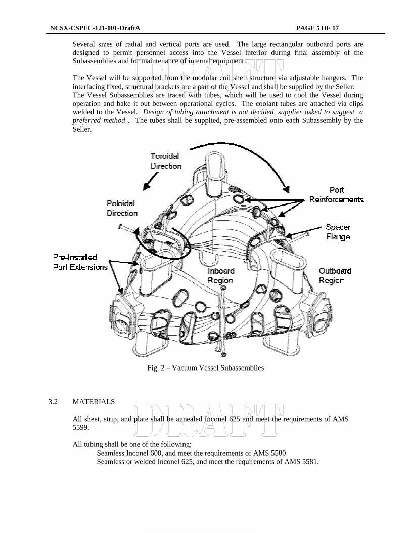
Several sizes of radial and vertical ports are used. The large rectangular outboard ports are designed to permit personnel access into the Vessel interior during final assembly of the Subassemblies and for maintenance of internal equipment. The Vessel will be supported from the modular coil shell structure via adjustable hangers. The interfacing fixed, structural brackets are a part of the Vessel and shall be supplied by the Seller. The Vessel Subassemblies are traced with tubes, which will be used to cool the Vessel during operation and bake it out between operational cycles. The coolant tubes are attached via clips welded to the Vessel. Design of tubing attachment is not decided, supplier asked to suggest a preferred method . The tubes shall be supplied, pre-assembled onto each Subassembly by the Seller.
Fig. 2 – Vacuum Vessel Subassemblies
3.2 MATERIALS
All sheet, strip, and plate shall be annealed Inconel 625 and meet the requirements of AMS 5599. All tubing shall be one of the following;
Seamless Inconel 600, and meet the requirements of AMS 5580. Seamless or welded Inconel 625, and meet the requirements of AMS 5581.
NCSX-CSPEC-121-001-DraftA PAGE 6 OF 17
All bar and structural shapes shall be annealed Inconel 625 and meet the requirements of AMS 5666. All conflat flanges shall be 304 or 304L stainless steel and meet the requirements of ASTM A240. All O-ring sealed flanges shall be Inconel 625 and meet the requirements of either AMS 5599 or AMS 5666.
3.3 WELDING All welding shall be done in accordance with welding procedures that are written and qualified in accordance with the ASME Code, Section IX. All welders and welding operators shall be qualified to these procedures in accordance with Section IX. Where practicable, all full penetration weld joints shall be of the single beveled joint type, with the joint root located on the vacuum exposed side of the joint, and with a minimum included angle of 45 degrees, except where otherwise noted on the drawings. Full penetration joints to be welded from both sides shall have the vacuum side welded using the GTAW process, followed by back-grinding on the non-vacuum side prior to completion of the joint. Exceptions require written Laboratory concurrence. Unless called out on the drawing in the tail of the weld symbol, the welds may be made by either the GTAW or GMAW processes. Welds using SMAW processes are not permitted. The welds called out to be welded by the GTAW process are, in general, seal welds and are to be 100% inspected. Dye penetrant is not permitted.
3.3.1 Weld Inspection and Examination All welds are to be visually inspected using a written procedure prepared in accordance with Article 9 of Section V of the ASME Code. The acceptance criteria for the visually inspected welds is given in AWS D1.1, paragraph 6.9 and Table 6.1. Welds designated with a V in the tail of the welds symbol shall also be visually examined with 8x magnification, in accordance with Article 6, Section V, of the ASME Code. All welds that do not meet the stated acceptance criteria shall be repaired, and re-inspected or re-examined.
3.3.2 Weld Inspector and Weld Examiner Qualifications Visual weld inspection shall be performed by inspectors certified to perform visual inspection of welds in accordance with AWS QC1 or SNT-TC-1A, Level II or Level III.
3.3.3 Weld filler metal Weld filler metal shall meet the requirements of the applicable AWS A series specifications or ASME SFA specifications. Certified material test reports shall be supplied for all materials (see section 4.3). Welding of stainless steel conflat flanges to Inconel 625 ports shall use ASME/AWS SFA/A 5.14 ERNiCr-3 or ERNiCrMo-3 filler metal.
3.4 PERFORMANCE REQUIREMENTS* The Vessel expected performance under normal operating conditions is as follows:
Operating temp 20 C Bake-out temperature 150 C Maximum total leak rate with port blanking covers 1 X 10⁻⁶ torr-l/s
NCSX-CSPEC-121-001-DraftA PAGE 7 OF 17
3.5 SURFACE QUALITY AND PREPARATION Interior (vacuum) surfaces of Inconel sheet stock used for fabrication of the Vessel wall and port standpipes shall be the identified and marked. The interior surfaces of the sheet stock shall be mechanically ground and electro-polished to a 32 micro-inch finish. Interior surfaces of pipe and tubing used for port stand pipes shall be electro-polished to a 32 micro-inch finish. Interior surface weld beads, scratches, and tooling marks resulting from fabrication shall be ground to a 32 micro-inch finish. Scratches, pits, weld pin holes and other surface imperfections exceeding 0.015 inches in depth shall be repaired by welding before finish grinding. Edges or surfaces of parts to be joined by welding shall be prepared by machining, grinding, or plasma arc cutting. Where thermal cutting is used, all scale must be removed by grinding. If permeability increase exceeds the criteria of paragraph 3.8.2, additional grinding may be required. Tools utilized in grinding and lapping operations on the Vessel and its components shall be nonferrous ceramics or nonmagnetic stainless steel, which have never been in contact with other than austenitic stainless material. Mill finish on the exterior surfaces of the vessel is acceptable, but any gouges greater than .03 inches deep shall be weld repaired and ground smooth. After completion of assembly and surface preparation, the Vessel interior shall be cleaned per the requirements of Section 3.11.
3.6 PORTS
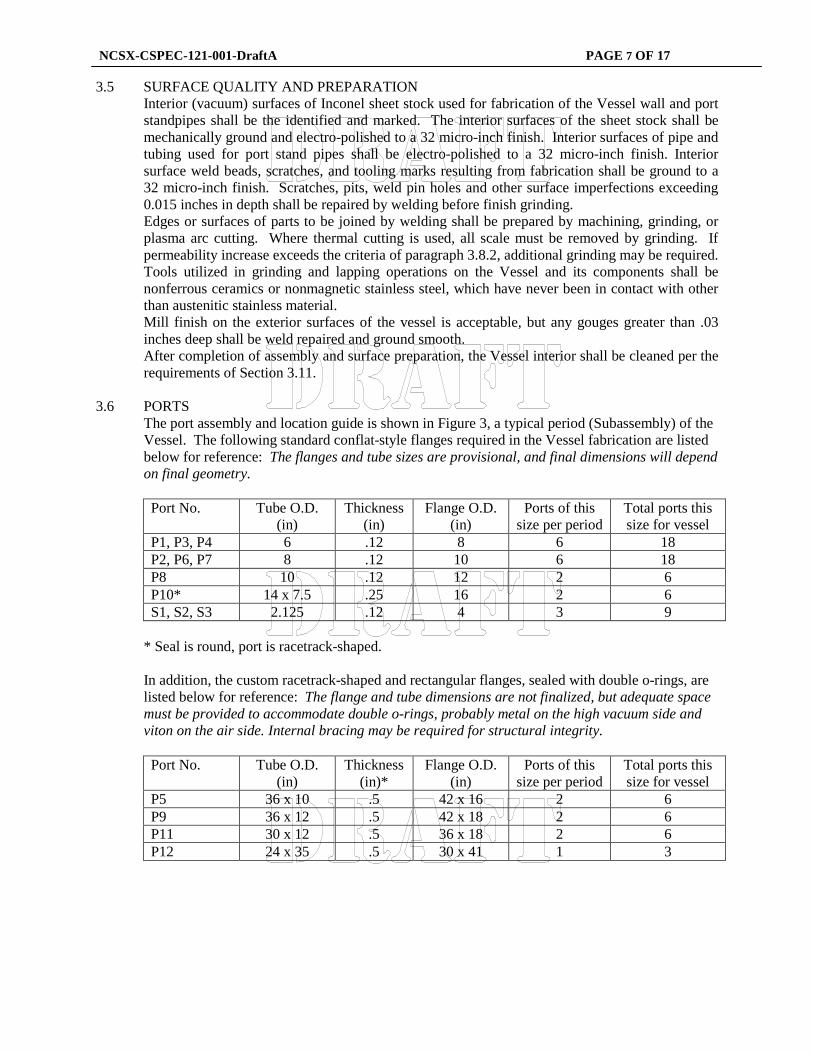
The port assembly and location guide is shown in Figure 3, a typical period (Subassembly) of the Vessel. The following standard conflat-style flanges required in the Vessel fabrication are listed below for reference: The flanges and tube sizes are provisional, and final dimensions will depend on final geometry.
Port No. Tube O.D.
(in) Thickness
(in) Flange O.D.
(in) Ports of this
size per period Total ports this size for vessel
P1, P3, P4 6 .12 8 6 18 P2, P6, P7 8 .12 10 6 18 P8 10 .12 12 2 6 P10* 14 x 7.5 .25 16 2 6 S1, S2, S3 2.125 .12 4 3 9
* Seal is round, port is racetrack-shaped. In addition, the custom racetrack-shaped and rectangular flanges, sealed with double o-rings, are listed below for reference: The flange and tube dimensions are not finalized, but adequate space must be provided to accommodate double o-rings, probably metal on the high vacuum side and viton on the air side. Internal bracing may be required for structural integrity. Port No. Tube O.D.
(in) Thickness
(in)* Flange O.D.
(in) Ports of this
size per period Total ports this size for vessel
P5 36 x 10 .5 42 x 16 2 6 P9 36 x 12 .5 42 x 18 2 6 P11 30 x 12 .5 36 x 18 2 6 P12 24 x 35 .5 30 x 41 1 3
NCSX-CSPEC-121-001-DraftA PAGE 8 OF 17
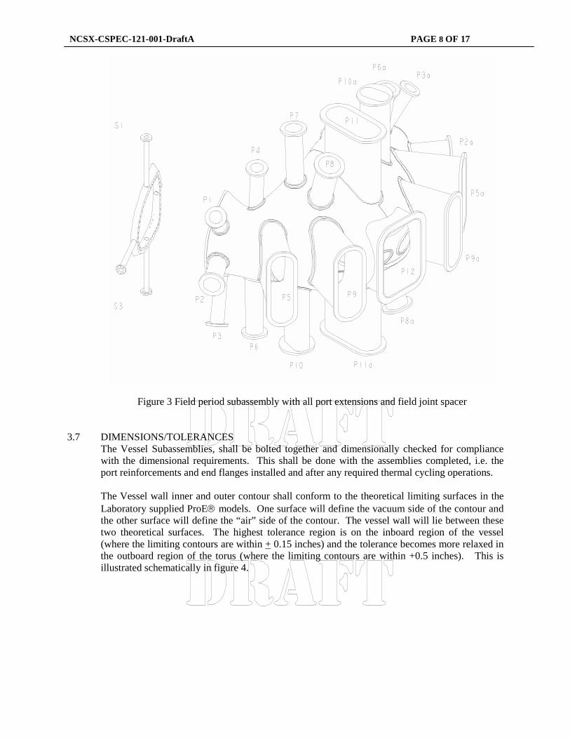
Figure 3 Field period subassembly with all port extensions and field joint spacer 3.7 DIMENSIONS/TOLERANCES
The Vessel Subassemblies, shall be bolted together and dimensionally checked for compliance with the dimensional requirements. This shall be done with the assemblies completed, i.e. the port reinforcements and end flanges installed and after any required thermal cycling operations. The Vessel wall inner and outer contour shall conform to the theoretical limiting surfaces in the Laboratory supplied ProE models. One surface will define the vacuum side of the contour and the other surface will define the “air” side of the contour. The vessel wall will lie between these two theoretical surfaces. The highest tolerance region is on the inboard region of the vessel (where the limiting contours are within + 0.15 inches) and the tolerance becomes more relaxed in the outboard region of the torus (where the limiting contours are within +0.5 inches). This is illustrated schematically in figure 4.

NCSX-CSPEC-121-001-DraftA PAGE 9 OF 17
Overall dimensions and dimensional tolerances shall be in accordance with the referenced Engineering Drawings. The Vessel wall thickness, after forming, shall be 0.375 +0.01/-0.12 inches. The port reinforcements shall be machined to receive its associated port extension subassembly such that the location of the flange can be located within the prescribed tolerance (tolerance tbd, but ~ within 0 .25 inches at both ends and perpendicular to the nominal port extension axis within~ 0.5 deg) The Seller will be required to perform dimensional checks using full surface 3-D measurement equipment (eg laser tracker) to ensure that the surfaces are within the prescribed limits. The seller shall also perform vessel wall thickness measurements using suitable method (e.g. ultrasonic).
3.8 FABRICATION 3.8.1 General Considerations
The demands of the application mandate strict adherence to the requirements of this specification. Distortion of the Vessel due to the welding processes is of special concern. It is emphasized that tolerances are critical, since the plasma facing components and diagnostics are mounted to, and are aligned by, the Vessel. Also, the Modular Coils, which define the shape of the plasma, are closely fitted to the Vessel and must be able to slip over it during assembly, making the Vessel contour very critical. Dimensional stability of the vessel over an operating temperature range of room temperature to 200 C is a primary requirement. Fixturing and stress relieving for the purpose of dimensional stability after welding will be necessary to maintain the Vessel's tolerances and to avoid
Tolerance zone inboard:~ 0.7 inch(including thickness)
Tolerance zone outboard:~ 1.4 inch
(including thickness TBD)
Tolerance zone inboard:~ 0.7 inch(including thickness)
Tolerance zone outboard:~ 1.4 inch
(including thickness TBD)
Figure 4 Vessel tolerance zone schematic

NCSX-CSPEC-121-001-DraftA PAGE 10 OF 17
subsequent distortion. . All fixturing equipment shall become the property of the Laboratory and shall be delivered to the Laboratory at conclusion of testing.
3.8.2 Cutting, Forming and Bending For the fabrication of the Vessel, all cutting, forming and bending shall be done in accordance with the ASME Boiler Code, Section VIII, Division 1. Strict controls shall be instituted during forming and fabrication to prevent contamination of the Inconel with ferritic materials. Verification from the Seller must be obtained to assure that the permeability and dimensional tolerances will be met to achieve the overall end product tolerance requirements.
3.8.3 Process The Vessel wall Subassemblies shall be fabricated by explosive forming, pressing, casting or other related processes that result in a smooth contour, conforming to the ProE model supplied by the Laboratory (section 3.7). Material properties after fabrication shall conform to specifications AMS 5599 or AMS 5666 for annealed Inconel 625, per MIL-HDBK-5D. If casting is proposed by the Seller, samples of after-cast material will be required to be submitted for analysis and approval by the Laboratory with the Approval Data.
3.8.4 Segmentation
The three Vessel Subassemblies are identical and are made up of contoured plate segments, welded together and mated to end flanges. A possible fabrication segmentation of a half Subassembly is shown in Figure 4, which uses 6 shapes and 12 total pieces to form a Subassembly. This configuration incorporates shapes that can be freely removed from a forming die without interference (entrapment) and minimizes the amount of plate deformation required during the forming process. The Seller may propose other segmentation schemes with the bid proposal for review and approval by the Laboratory. Schemes minimizing the number of segments (and subsequent welding) are preferred to schemes using more segments.
Figure 5 Fabrication segmentation scheme for a half period section of the Vessel.
3.8.5 Port reinforcements
Each port location shall be fitted with a welded port reinforcement which will serve the following functions:

NCSX-CSPEC-121-001-DraftA PAGE 11 OF 17
a. Port structural reinforcement. b. Weld interface for installation and alignment of the port extension. c. Port cover for leak checking of the Vessel
The port reinforcements shall be welded into the vessel as solid plates and the port extension holes shall be final machined into the reinforcements after leak check of the Vessel is completed. Figure 6 shows a cross-section through a port reinforcement after installation and final machining. The reinforcement final machined configuration, shall meet the dimensional requirements detailed in the Engineering Drawings. The reinforcement welding blanks may be fabricated as machinings, forgings, or castings, at the discretion of the Seller. The reinforcement blank designs shall be submitted to the Laboratory as a part of the Approval Data.
3.9 FASTENERS
Conflat flanges shall use 304 SS, silver plated, 12 point bolt kits provided with flanges from the flange manufacturer. Rectangular o-ring ports shall use ASME SA 453 Grade 660 bolts.(A286 or Inco 718) Vessel Subassembly flanges shall use .(A286 or Inco 718)bolts
Fig. 6 – Port Reinforcement

NCSX-CSPEC-121-001-DraftA PAGE 12 OF 17
3.10 SEALS
Conflat flanges shall use standard copper seals provided from the flange manufacturer. Rectangular ports and Vessel Subassembly flanges shall be sealed with double seals, with differential vacuum pumping ducts provided between seals.
Vacuum side o-rings are tbd (may be viton or Helicoflex seals), conforming to specifications listed in the Engineering Drawings. Atmosphere side o-rings shall be Viton A with dimensions and o-ring grooves conforming to specifications listed in the Engineering Drawings.
3.11 CLEANING
The Seller shall submit a Cleaning Procedure with the bid proposal that details procedures, cleaning material, and protective packaging which will be used on the Vessel vacuum surfaces before delivery to the Laboratory Site. As a minimum this procedure will include:
a. Vapor degreasing to remove oils, greases, and die lubricant residues resulting from
handling and fabrication of the Vessel. b. Solvent (e.g. ethanol) wipe down of the surfaces. c. Blow drying of surfaces with oil-free instrument air. d. Use of lint-free wipes. e. Test procedure to confirm surface cleanliness.
3.12 PERMEABILITY Overall relative magnetic permeability of the fabricated and welded sections shall be less than or equal to 1.01, except at welds involving austenitic stainless steel (i.e. port extension flanges) where less than or equal to 1.05 is allowed. Relative magnetic permeability of bolts at the sector-to-sector joints will be less than 1.01. Any other Seller supplied bolts or flanges shall be less than or equal to 1.02.
3.13 INSTALLATION
The Seller shall furnish the Laboratory with the vessel all special purpose handling fixtures and rigging used during fabrication as well as documentation describing their use. Upon award of contract, the Seller shall provide the Laboratory a list of equipment necessary to perform final check out and alignments. All tools, i.e., electronic indicators, levels, etc. necessary to perform the installation and on site tests will be supplied by the Laboratory. The Seller shall provide this list of tools at least 8 weeks in advance of delivery
3.14 DELIVERABLES The Seller is responsible for delivering to the laboratory the following:
3.14.1 All documentation listed in section 6.0. 3.14.2 A completed Vessel consisting of three subassemblies and all port assemblies, which have
successfully passed all acceptance tests and criteria. 3.14.3 Fixtures or tooling fabricated solely for the fabrication of the Vessel.
NCSX-CSPEC-121-001-DraftA PAGE 13 OF 17
4.0 QUALITY ASSURANCE REQUIREMENTS 4.1 QUALITY ASSURANCE PLAN
The Seller shall submit with the offer a copy of their general quality assurance plan with documented evidence showing how the Seller intends to comply with all requirements of this specification. After award of the subcontract and prior to fabrication, a final Quality Assurance Plan specific for this equipment shall be submitted to the Laboratory for approval. This Quality Assurance Plan shall be of sufficient detail and scope to allow the Laboratory to determine the quality control that can be expected from the Seller. This plan shall describe the Quality Assurance policies and practices that will be used to ensure the product meets specified requirements and will perform its intended function.
Seller shall prepare and submit for Laboratory review and approval a Manufacturing/Inspection/Test Plan, which identifies parts, sub-assemblies, etc.; shows their integrated flow into end items; and identifies critical manufacturing operations as well as inspections and tests. Preparing the Plan may include developing a flow chart and generating Process Sheets/Shop Travelers, etc. The Laboratory may designate selected manufacturing, inspection and/or test operations as mandatory “witness” points based on the MIT plan. Seller shall provide Laboratory with five (5) working days notice in advance of such witness points.
4.2 INSPECTION/ SURVEILLANCE/AUDIT BY NCSX PROJECT
Authorized representatives of the Laboratory and the U. S. Government shall have the right at all reasonable times to visit the Seller's premises and those of Seller's suppliers during the performance of the procurement for the purposes of inspection, surveillance, audit and/or obtaining any required information as may be necessary to assure that items or services are being furnished in accordance with specified requirements. Such visits shall be coordinated with the Seller's personnel to minimize interference with the normal operations of said premises. The Seller shall make available records and documentation necessary for this function and shall provide all reasonable facilities and assistance for the safety and convenience of Laboratory and/or U. S. Government representatives in the performance of their duties. The Laboratory and the U. S. Government recognize the Seller's right to withhold information concerning proprietary processes. The Seller agrees to insert the paragraph above in each lower tier procurement issued hereunder.
4.3 SELLER’S RESPONSIBILITY FOR CONFORMANCE
Neither Laboratory review and/or approval of Seller's documents nor Laboratory inspection of Seller's items or services shall relieve the Seller of responsibility for full compliance with requirements of the purchase order/contract.
4.4 INSPECTION AND TEST PROCEDURES
Inspections and tests shall be performed in accordance with written procedures referencing criteria for acceptance or rejection. Each inspection and test shall be documented.
4.5 DOCUMENT TRACEABILITY AND RECORDS The Seller shall maintain a system of documentation whereby objective evidence of required
operations, inspections, examinations, and tests is systematically compiled, indexed and stored. Such objective evidence may include "travelers"; and material test, certification, inspection, examination, test and discrepancy reports; which shall be complete, legible, and validated by responsible personnel and shall be traceable to subject items.
NCSX-CSPEC-121-001-DraftA PAGE 14 OF 17
4.6 EQUIPMENT/MATERIAL IDENTIFICATION AND STATUS Material and equipment identification shall be maintained throughout the program and be
traceable to the records. Status of acceptability shall be readily discernible through the Seller's use of tags, stamps, serial numbers or other positive means.
4.7 CALIBRATION OF TEST AND MEASURING EQUIPMENT Inspections and tests shall be performed using properly calibrated measuring and test equipment.
Seller shall have in its possession the necessary equipment to perform the required inspections and tests. Calibration standards shall be traceable to the National Institute for Standards and Technology (NIST) or equivalent. Seller shall impose these calibration requirements on sub tier suppliers.
4.8 CONTROL OF SPECIAL PROCESSES
Seller shall use trained and qualified personnel and qualified written procedures in accordance with specified requirements for the performance of certain special processes, including but not limited to, soldering, electronic assembly, brazing, welding, plating, heat treatment, nondestructive examination, etc. Copies of special process procedures shall be available for review by the Laboratory and submitted to the Laboratory for review and approval if requested.
4.9 RELEASE FOR SHIPMENT FORM Seller shall have a signed "Product Quality Certification and Shipping Release" Form to be
provided by the Laboratory Quality Assurance Representative prior to Laboratory acceptance of procured items or services for full or partial shipment. The Laboratory reserves the right to refuse to accept shipments unless accompanied by a signed "Shipping Release" Form .
4.10 PROCESS HISTORY Seller shall provide to the Laboratory a Process History, which includes a compilation of
documents, detailing the objective evidence of the acceptability of the work performed. The Process History shall include as a minimum, but not be limited to, the following:
4.11 MATERIAL CERTIFICATIONS
The Seller shall submit copies of inspection reports, test data, and/or certifications from vendors, showing relevant chemical, mechanical and electrical properties of materials used, where applicable, as well as documents showing adherence to in-process requirements. Material certifications from sub-tier suppliers shall also be submitted.
4.11.1 Inspection and Test Reports
Copies of the original reports of all required inspections, tests and examinations, properly validated by authorized personnel.
4.11.2 Fabrication Drawings
Copies of the final fabrication “as built” drawings that include all approved changes made during the fabrication.
4.11.3 Certificate of Compliance (C of C)
Seller's C of C, stating that the work performed conforms in every respect to the physical configuration and functional inspection/test requirements. Seller’s Quality Assurance (QA) Manager shall sign the C of C. Where Laboratory -furnished material has been used by the Seller, such certification shall also include the statement: "Material furnished by Laboratory has been inspected by the Seller and used by the Seller as specified by Laboratory with no unauthorized substitutions.
NCSX-CSPEC-121-001-DraftA PAGE 15 OF 17
4.12 RECEIVING/INSPECTION
The Laboratory will perform Receiving Inspection on items or services supplied by Seller, using either a sampling plan or 100% inspection. Discrepant items or services will be rejected and returned to Seller or reworked by NCSX Project. Costs caused by rejects will be charged to Seller.
4.13 TESTING 4.13.1 Leak Check
A helium leak test of the Vessel and port extensions shall be performed at Seller’s facility. Vessel testing shall be prior to final boring and machining of the port extension holes in the port reinforcements, in accordance with ASTME 498 and as delineated in the following paragraphs: The vessel shall be leak checked in its entirety by temporarily bolting together the Subassemblies with the appropriate flange seals. This test shall be performed a minimum of three times after cycling the temperature of the vessel from room temperature to 200 C. The leak check procedure will also be performed at 150C. The Seller shall furnish and install all temporary test fixtures, flanges, blanking off plates, and gaskets required to seal the ports for leak checking purposes. All such equipment shall be delivered to the Laboratory at the conclusion of testing. The port extension assemblies shall be tested by blanking them off with suitable covers. The blanking covers shall be supplied by the Seller and their design shall be submitted for approval by the Laboratory. The inspection report format and output requirements shall also be demonstrated and documented as tested. A Turbomolecular Pump (TMP) and a mechanical vacuum pump shall be used to evacuate the assembly under test. A mass spectrometer leak detector shall be connected to the TMP fore-line. A detection sensitivity of 10-10 scc/sec shall be provided. The port component under test shall be enclosed with a polyethylene or Mylar film bag. The volume enclosed by the bag shall be capable of being filled with helium gas. The vacuum component under test shall be evacuated using the TMP to an internal pressure of less than or equal to 10-5 torr. The plastic bag shall be filled with helium and the total helium leak rate shall be measured. The total helium leak rate shall not exceed 1.7 x 10⁻⁹ scc/sec at an internal pressure of less than or equal to 10-5 torr. Each component leak rate shall be recorded and provided to the Laboratory after each test. For the testing of each port, one port at a time, a test fixture, supplied by Seller, may be installed for sealing the port under test on the inboard side, including provision for connection of a high vacuum pump. Design of test fixture shall be proposed by Seller and approved by the Laboratory. Tests shall be conducted, and results recorded, in accordance with Laboratory approved test procedures. All leaks found shall be documented on nonconformance reports, and repaired. Seller's leak repair procedures shall be submitted to the Laboratory for approval prior to use.
4.13.2 Acceptance Test The Vessel Subassemblies shall be bolted together on an assembly fixture and inspected and tested with documented results to show full compliance with the subcontract requirements at the Seller’s plant and at the installation site. The Laboratory shall have the discretion of exercising the right to witness any or all of the Vessel alignment and accuracy checks, and leak check tests
NCSX-CSPEC-121-001-DraftA PAGE 16 OF 17
of the Vessel components at the Seller’s facility. The documentation of the results of the testing at the Seller’s facility shall become a part of the Vessel acceptance for shipment. The Laboratory will describe any or all of these identical Vessel checks to be performed at the Laboratory’s site during installation. The documented results for requirements for the testing at the Laboratory’s site shall become a part of the Vessel final acceptance.
4.13.3 Final Acceptance at Laboratory Site
The Vessel components will be shipped immediately after successful completion of the activities described in Section 4.2.2 for implementation at the Laboratory site. The Laboratory shall have a 90 day period after successful implementation to identify any defects by testing against the Seller’s documentation. The Seller shall repair any defects discovered during this period.
4.13.4 Test at the Installation Site
The Laboratory shall conduct leak testing and dimensional inspection at the installation site per requirements specified in 4.2.2. These results shall conform with the subcontract requirements and will be the basis for final acceptance of the machine.
4.13.5 All materials used for the vessel, flanges, fasteners and seals shall be new and un-used. The seller
shall implement procedures to verify that the items conform to all applicable specifications and be traceable to mill certifications.
5.0 PREPARATION FOR DELIVERY 5.1 LABELING
A corrosion-resistant, non-magnetic, metal name plate shall be attached to each major component. This name plate shall be plainly and permanently marked with the following information: Seller’s name Machine model number Machine serial number Date of manufacture (month and year) Contract number
Vessel Subassemblies and components shall be marked to provide positive identification to a machine. When such markings impairs proper functioning of the equipment, a metal tag shall be used.
5.2 PACKING AND SKIDDING
All the components shall be sealed, packaged, and skidded to provide protection against contamination, deterioration and damage during shipment. The plan shall include a description of methods to be used to preserve, package, skid, and identify equipment. The Seller shall contact the Laboratory ten days prior to shipment of the machine to confirm shipping method and route.
5.3 MARKING
Each shipping skid shall be marked with the name of the Seller, Laboratory Purchase Order Number, the component, Seller’s Model Number, and gross weight. Boxes containing loose parts, attachments, and accessories shall be marked identifying the machine to which they belong, and where possible, boxes are to be secured to the skid of the unit.
6.0 MANUFACTURERS DATA

NCSX-CSPEC-121-001-DraftA PAGE 17 OF 17
Manufacturer’s data itemized on attachments DS-PEX00003-A01-1, -2, -3, and –4 shall be furnished and transmitted by the Seller to the Laboratory by the dates specified. These data sheets list the information required for the Laboratory to adequately evaluate the Seller’s offer, obtain engineering requirements for Vessel installation, and obtain certified data for operation at the Laboratory’s facility.
6.1 Offer Appraisal Data Information considered sufficient to allow a technical evaluation of a manufacturer’s proposal, offer, and/or product.
6.2 Advanced Engineering Data
Design information that is sufficient to enable the Laboratory to complete the equipment installation design or initiate preliminary material processing.
6.3 Design Approval data
Information required to ensure the manufacturer has an adequate understanding of specified requirements. Design approval data are generally in the form of preliminary or conceptual drawings, sketches, block diagrams, and/or flow charts.
6.4 Certified data Detailed information that allows for complete installation, operation, maintenance, and repair of equipment or certification of materials for their intended use.