equipment. - files.udc.edufiles.udc.edu/docs/facilities/seas_laboratory_renovation/amendment... ·...
82
Transcript of equipment. - files.udc.edufiles.udc.edu/docs/facilities/seas_laboratory_renovation/amendment... ·...


University of the District of Columbia
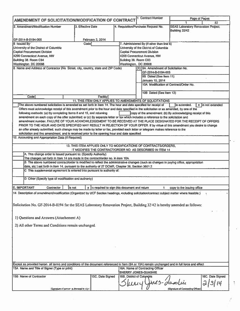
School of Engineering and Applied Sciences Laboratory Renovation
Project Number: 13334.01
Addendum 2 – Revision 2
01.31.2014
NOTE: This document replaces Addendum 1 – Revision 1 Document previously issued.
SPECIFICATIONS SECTIONS
1. Add Section 03 30 00 ‐ Cast‐in‐Place Concrete
2. Add Section 08 71 13 ‐ Automatic Door Operators
3. Add Section 12 48 23 ‐ Entrance Floor Grids
4. Add Section 10 14 10 ‐ Interior Signage
5. Add Section 13 28 00 ‐ Hazardous Materials Remediation – General
6. Add Section 13 28 10 ‐ Hazardous Waste Management
7. Add Section 13 28 20 ‐ Removal and Disposal of ACM’s
8. Replace Section 23 82 16.14 ‐ Coils.
9. Remove 23 82 16.14 from Division 26 and move to Division 23
10. Add Section 23 07 13 – Duct Insulation
ARCHITECTURAL DRAWINGS
G‐001 Replace this sheet.
G‐006
1. PLAN REVISION: Refer to Revised Sheet A‐110 for plan revisions at the following locations: C06
Signal Closet; C07 Power Systems Lab; C08A Civil Grad Research Office
G‐012
1. PLAN REVISION: Refer to Revised Sheet A‐110 for plan revisions at the following locations: C06
Signal Closet; C07 Power Systems Lab; C08A Civil Grad Research Office
AD‐101
1. PLAN REVISION: Revise Plan 1 Demolition Level C per Sketch AD‐111a.
2. PLAN CHANGE: Signal Closet (C06) is Not in Contract per Sketch AD‐111a.
3. DEMOLITION GENERAL NOTES:
a. Delete Demolition General Note 22
b. Revise Demolition General Note 4 as follows: “CONTRACTOR SHALL FIELD VERIFY THEIR
WORK WITH THE DEMOLITION DRAWINGS, NEW CONSTRUCTION DRAWINGS,

SPECIFICATIONS AND EXISTING CONDITIONS. CONTRACTOR ARE RESPONSIBLE TO FIELD
VERIFY THE EXTENT OF DEMOLITION WORK PRIOR TO BIDDING AND FOR
COORDINATING THE EXTENT OF DEMOLITION WITH THE INSTALLATION OF NEW
SYSTEMS AND FINISHES INDICATED IN THE CONTRACT DOCUMENTS. CONTRACTOR
SHALL IMMEDIATELY NOTIFY THE DESIGN‐BUILDER OF ANY DISCREPANCIES BEFORE
COMMENCING WITH WORK.
c. Revise Demolition General Note 5 as follows: “CONTRACTOR SHALL FIELD VERIFY ALL
EXISTING FLOOR, WALL, CEILING AND ROOF CONSTRUCTION AND HEIGHTS PRIOR TO
COMMENCEMENT OF THE WORK. CONTRACTOR SHALL VERIFY ALL DIMENSIONS AND
CLEARANCES BEFORE COMMENCING WITH WORK. COMMENCEMENT OF THE WORK
CONSTITUTES ACCEPTANCE OF THE EXISTING CONDITIONS. CONTRACTOR SHALL
IMMEDIATELY NOTIFY THE OWNER'S REPRESENTATIVE OF ANY DISCREPANCIES BEFORE
COMMENCING WITH WORK.”
d. Revise Demolition General Note 6 as follows: “ CONTRACTOR SHALL MAINTAIN ALL
LEGAL EGRESS FROM EXISTING BUILDING.”
e. Revise Demolition General Note 8 as follows: “CONTRACTOR ARE RESPONSIBLE FOR ALL
OTHER ITEMS TO BE REMOVED AND SALVAGED.”
f. Revise Demolition General Note 17 as follows: “CONTRACTOR SHALL CUT AND PATCH
EXISTING CAST‐IN‐PLACE CONCRETE FLOOR SLAB AS REQUIRED FOR ALL BELOW‐FLOOR
WORK. COORDINATE ALL WORK WITH APPROPRIATE AND AFFECTED TRADES. WHERE
REQUIRED OR INDICATED, NEATLY AND CLEANLY SAW‐CUT AND REMOVE THE CAST‐IN‐
PLACE CONCRETE SLAB, EXCAVATE AND REMOVE SUB BASE AS REQUIRED FOR THE
INSTALLATION OF BELOW‐FLOOR WORK. WIDTH OF TRENCH SHALL BE AS REQUIRED TO
FURNISH AND INSTALL THE WORK WITHOUT UNDERMINING THE ADJACENT CAST‐IN‐
PLACE CONCRETE FLOOR. BACKFILL WITH GRANULAR FILL. PATCH AND REPAIR CAST‐IN‐
PLACE CONCRETE FLOOR TO MATCH ADJACENT EXISTING FLOOR SURFACE WITH SAME
FINISH MATERIAL.”
AD‐102
Demolition General Notes No. 4, No. 5, No.6, No. 8 and No. 17 have been revised. And note No.22 have
been eliminated. (Refer to AD‐101 Item 3 above)
AD‐103
Demolition General Notes No. 4, No. 5, No.6, No. 8 and No. 17 have been revised. And note No.22 have
been eliminated. (Refer to AD‐101 Item 3 above)
AD‐111
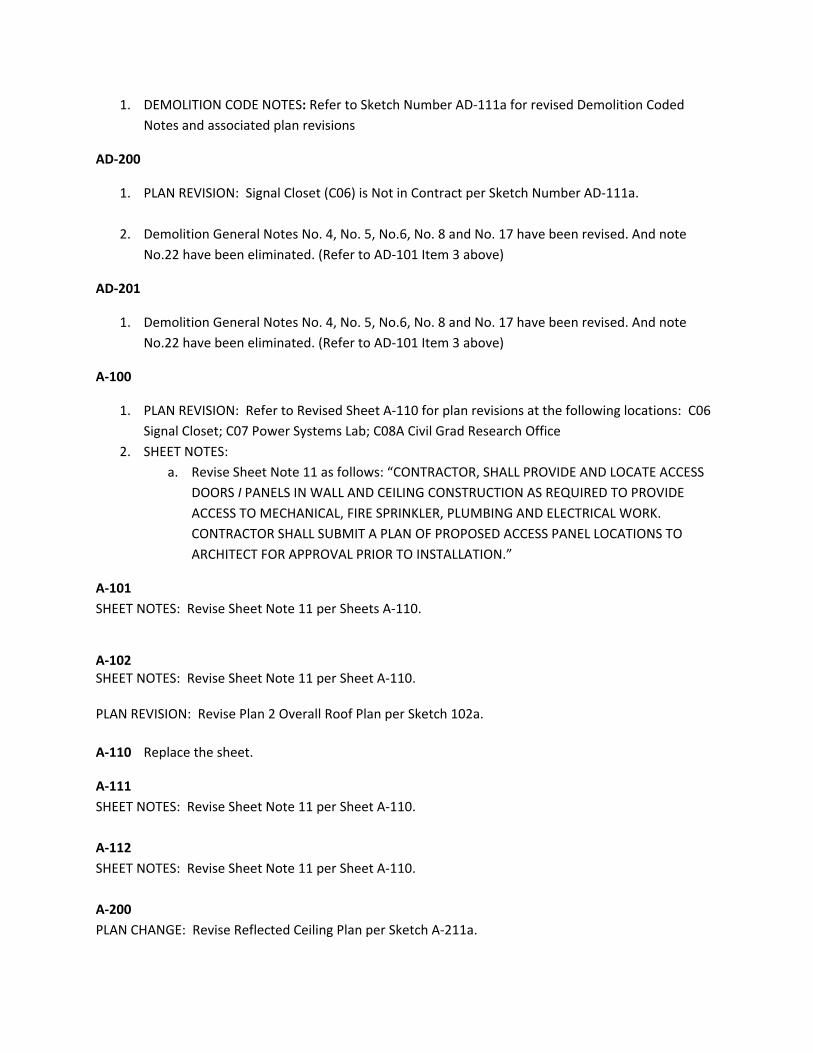
1. DEMOLITION CODE NOTES: Refer to Sketch Number AD‐111a for revised Demolition Coded
Notes and associated plan revisions
AD‐200
1. PLAN REVISION: Signal Closet (C06) is Not in Contract per Sketch Number AD‐111a.
2. Demolition General Notes No. 4, No. 5, No.6, No. 8 and No. 17 have been revised. And note
No.22 have been eliminated. (Refer to AD‐101 Item 3 above)
AD‐201
1. Demolition General Notes No. 4, No. 5, No.6, No. 8 and No. 17 have been revised. And note
No.22 have been eliminated. (Refer to AD‐101 Item 3 above)
A‐100
1. PLAN REVISION: Refer to Revised Sheet A‐110 for plan revisions at the following locations: C06
Signal Closet; C07 Power Systems Lab; C08A Civil Grad Research Office
2. SHEET NOTES:
a. Revise Sheet Note 11 as follows: “CONTRACTOR, SHALL PROVIDE AND LOCATE ACCESS
DOORS I PANELS IN WALL AND CEILING CONSTRUCTION AS REQUIRED TO PROVIDE
ACCESS TO MECHANICAL, FIRE SPRINKLER, PLUMBING AND ELECTRICAL WORK.
CONTRACTOR SHALL SUBMIT A PLAN OF PROPOSED ACCESS PANEL LOCATIONS TO
ARCHITECT FOR APPROVAL PRIOR TO INSTALLATION.”
A‐101
SHEET NOTES: Revise Sheet Note 11 per Sheets A‐110.
A‐102 SHEET NOTES: Revise Sheet Note 11 per Sheet A‐110. PLAN REVISION: Revise Plan 2 Overall Roof Plan per Sketch 102a.
A‐110 Replace the sheet.
A‐111
SHEET NOTES: Revise Sheet Note 11 per Sheet A‐110.
A‐112
SHEET NOTES: Revise Sheet Note 11 per Sheet A‐110.
A‐200
PLAN CHANGE: Revise Reflected Ceiling Plan per Sketch A‐211a.

A‐211
PLAN CHANGE: Revise Reflected Ceiling Plan per Sketch A‐211a.
A‐302 NEW SHEET: A‐302 Storefront Demolition Plans
A‐304 NEW SHEET: A‐304 Storefront New Work Plans
A‐308 NEW SHEET: A‐308 Storefront Elevations
A‐318 NEW SHEET: A‐318 Schedule and Details
A‐500 REPLACE Sheet A500.
A‐700
FINISH SCHEDULE: Revise Finish Schedule per attached Sketch A‐700a.
A‐701
FINISH FLOOR PLAN: Revise Plan 1/A701 per Sketch A701a.
A‐800
FF&E SCHEDULE: Revise FF&E Schedule per attached Sketch A‐800a.
A‐802
FURNITURE LAYOUT: Revise Furniture Layout per attached Sketch A‐802a.
A‐900 Replace this Sheet.
A‐901
PLAN REVISION: Revise Plan 1 Signage Level C – Part 1 per Sketch A901a.
A‐902
PLAN REVISION: Revise Plan 2 Signage Level C ‐ Part 2 per Sketch A‐901b.
Q‐201
1. PLAN REVISION: Room C07 Power Systems Lab
a. Identify Equipment Number 157 as “Existing”.
b. Identify Equipment Number 158 as “Existing”
c. Identify Equipment Number 160 as “Existing”.
d. Identify Equipment Number 161 as “Existing”
e. Identify Equipment Number 162 as “Existing”.
Q‐601
1. GENERAL NOTES: Added a General Note 1: 1. REFER TO MECHANICAL SCHEDULES AND DETAILS
FOR EXHAUST FAN SCHEDULE AND FUME HOOD CONNECTION DETAIL
2. Add Fume Hood Schedule per Sketch Q‐601a.
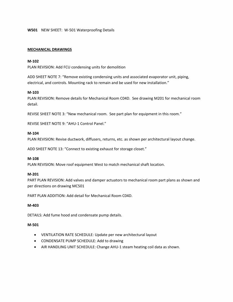
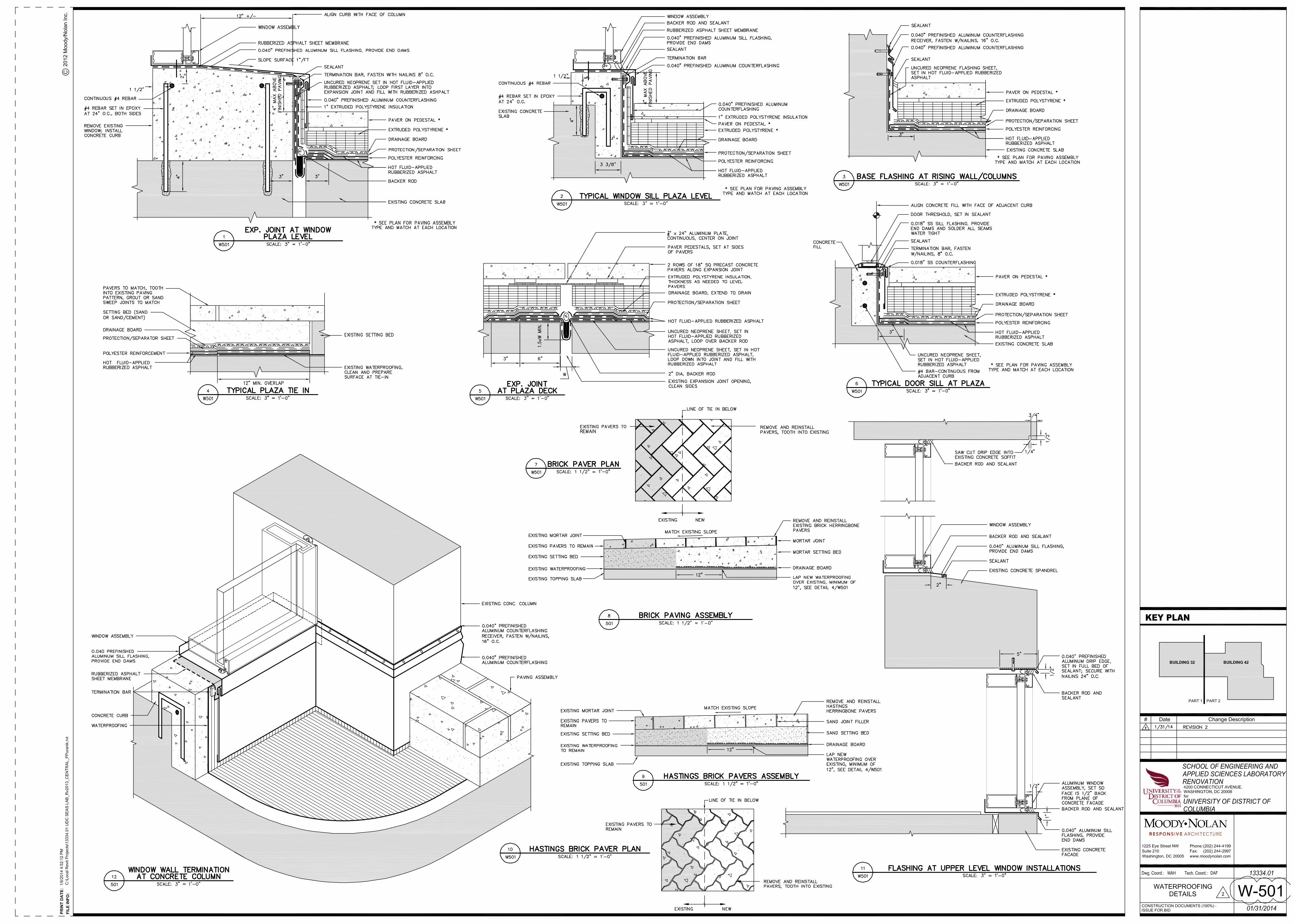
W501 NEW SHEET: W‐501 Waterproofing Details
MECHANICAL DRAWINGS
M‐102
PLAN REVISION: Add FCU condensing units for demolition
ADD SHEET NOTE 7: “Remove existing condensing units and associated evaporator unit, piping,
electrical, and controls. Mounting rack to remain and be used for new installation.”
M‐103
PLAN REVISION: Remove details for Mechanical Room C04D. See drawing M201 for mechanical room
detail.
REVISE SHEET NOTE 3: “New mechanical room. See part plan for equipment in this room.”
REVISE SHEET NOTE 9: “AHU‐1 Control Panel.”
M‐104
PLAN REVISION: Revise ductwork, diffusers, returns, etc. as shown per architectural layout change.
ADD SHEET NOTE 13: “Connect to existing exhaust for storage closet.”
M‐108
PLAN REVISION: Move roof equipment West to match mechanical shaft location.
M‐201
PART PLAN REVISION: Add valves and damper actuators to mechanical room part plans as shown and
per directions on drawing MC501
PART PLAN ADDITION: Add detail for Mechanical Room C04D.
M‐403
DETAILS: Add fume hood and condensate pump details.
M‐501
VENTILATION RATE SCHEDULE: Update per new architectural layout
CONDENSATE PUMP SCHEDULE: Add to drawing
AIR HANDLING UNIT SCHEDULE: Change AHU‐1 steam heating coil data as shown.

PLUMBING DRAWINGS
P‐104
PLAN REVISION: Add temporary location for compressor serving equipment in C12
PLAN REVISION: Add air dryer for laboratory compressed air in C Level Mechanical Room
ADD SHEET NOTE 20: “Temporary relocation point of remote air compressor serving
spectrometer lab #C12. Provide all temporary power, piping, conduit, etc. required to maintain
operation throughout the construction process. Coordinate and associated service outages with
the owner and other disciplines performing work in this lab area.”
P‐106
PLAN REVISION: Add NG drop symbol in cleanroom utilities closet to make shut‐off valves
accessible.
PLAN REVISION: Add callout note to rack pipes on wall
PLAN REVISION: Add callout note to provide “unistrut or trapeze pipe holder.”
ELECTRICAL DRAWINGS
E‐102
PLAN REVISION: Change light fixtures and light switch to equipment to remain in room C06
ADD SHEET NOTE 6: “Light fixtures and light switched ot remain in this room. Disconnect
lighting circuit serving this room and retain for reconnection. See Dwg E‐104.”
E‐104
PLAN REVISION: Change light fixtures and switch in storage room to existing to remain.
PLAN REVISION: Revise light fixture layout in rooms C07 & C08A per new architectural layout.
ADD SHEET NOTE 7: “Existing light fixtures in this room to be connected to new lighting circuit
2HC1‐1 as shown.”
E‐106
PLAN REVISION: Change receptacles and junction box to equipment to remain in room C06.
ADD SHEET NOTE 4: “Outlets and receptacles to remain in this room. Disconnect associated
branch circuit and salvage for reconnection. See Drawing E108.”
E‐107
PLAN REVISION: Add new electrical connection for condensate pump and mechanical control
panel in new mechanical room C04D. NOTE: This revision is shown on sketch E108A
E‐108
PLAN REVISION: Change receptacles and junction box to existing to remain in room C06 (E108A).

PLAN REVISION: Change power distribution of electrical equipment in Power Lab room C07 and
in room C08A (E108A).
REVISE SHEET NOTE 9: “Not used.” (E108A)
ADD SHEET NOTE 18: “Existing power outlets in this room to be reconnected to new spare
circuit breaker in panel 2LC‐PL” (E108A)
PLAN REVISION: Add branch circuit number to neutralizer sump pump (E108B)
PLAN REVISION: Delete disconnect switch and add single receptacle for neutralizer sump pump
connection. (E108B)
PLAN REVISION: Delete duplication of surface mounted raceway in lab C10B. (E108B)
PLAN REVISION: Add automatic door operator to the 2nd entrance door at Entry Vestibule C03.
(E108B)
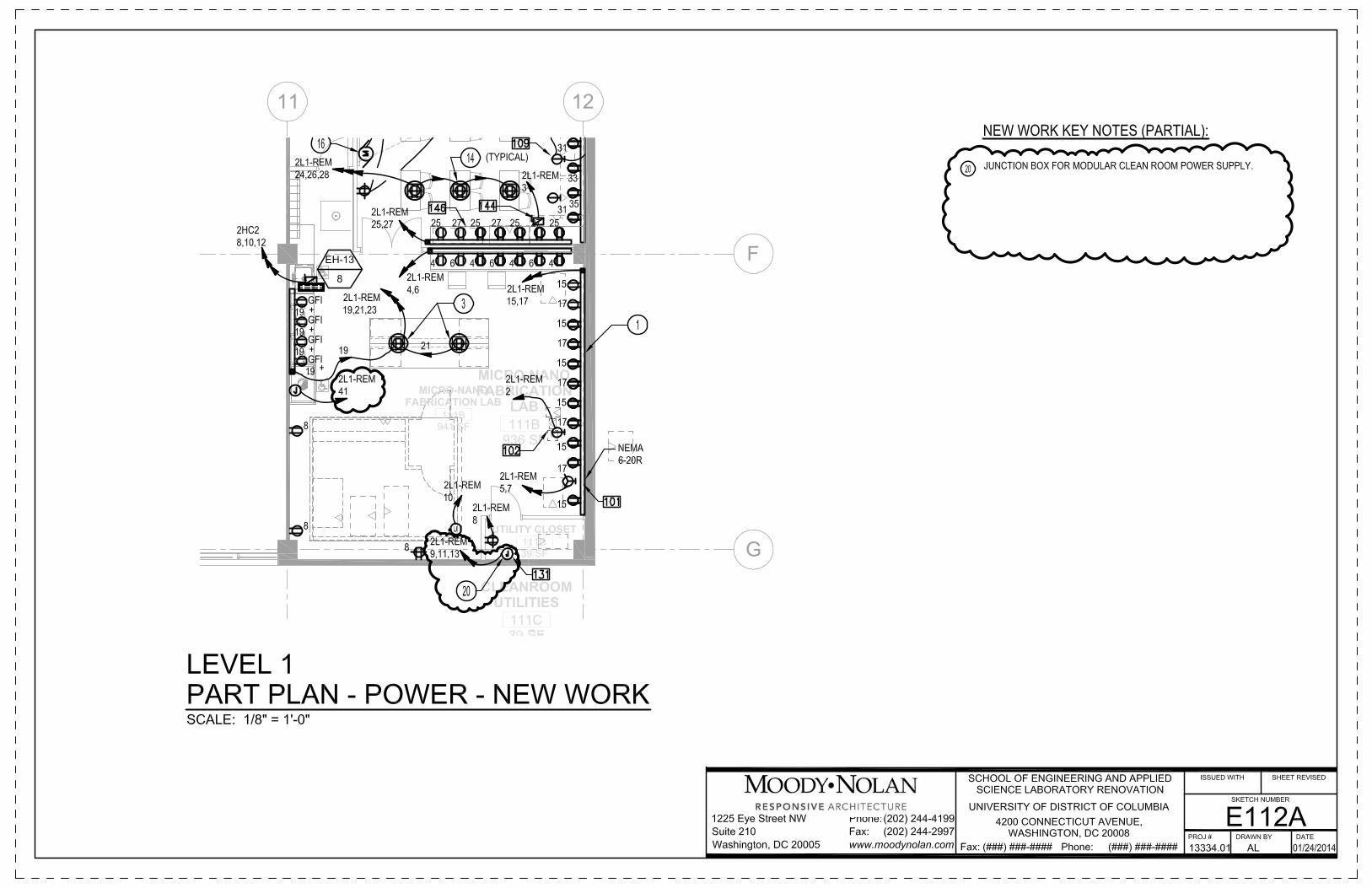
E‐112
PLAN REVISION: Delete receptacle NEMA 6‐30R in room 111B. (E112A)
PLAN REVISION: Add junction box at utility closet 111C for new power to Modular Clean Room.
(E112A)
ADD SHEET NOTE 20: “Junction box for modular clean room power supply.” (E112A)
ADD SHEET NOTE 19: “Run new home runs of new fans to panel 2H2 via existing roof
penetration. Contractor to verify.” (E112B)
PLAN REVISION: Replace panel 2L2‐P with new panel 2L2‐P (E112C)
ADD SHEET NOTE 21: “Replace panel 2L2‐P with new panel 2L2‐P 150A, 208/120V, 3ph., 4 wire.
Provide per panel schedule.” (E112C)
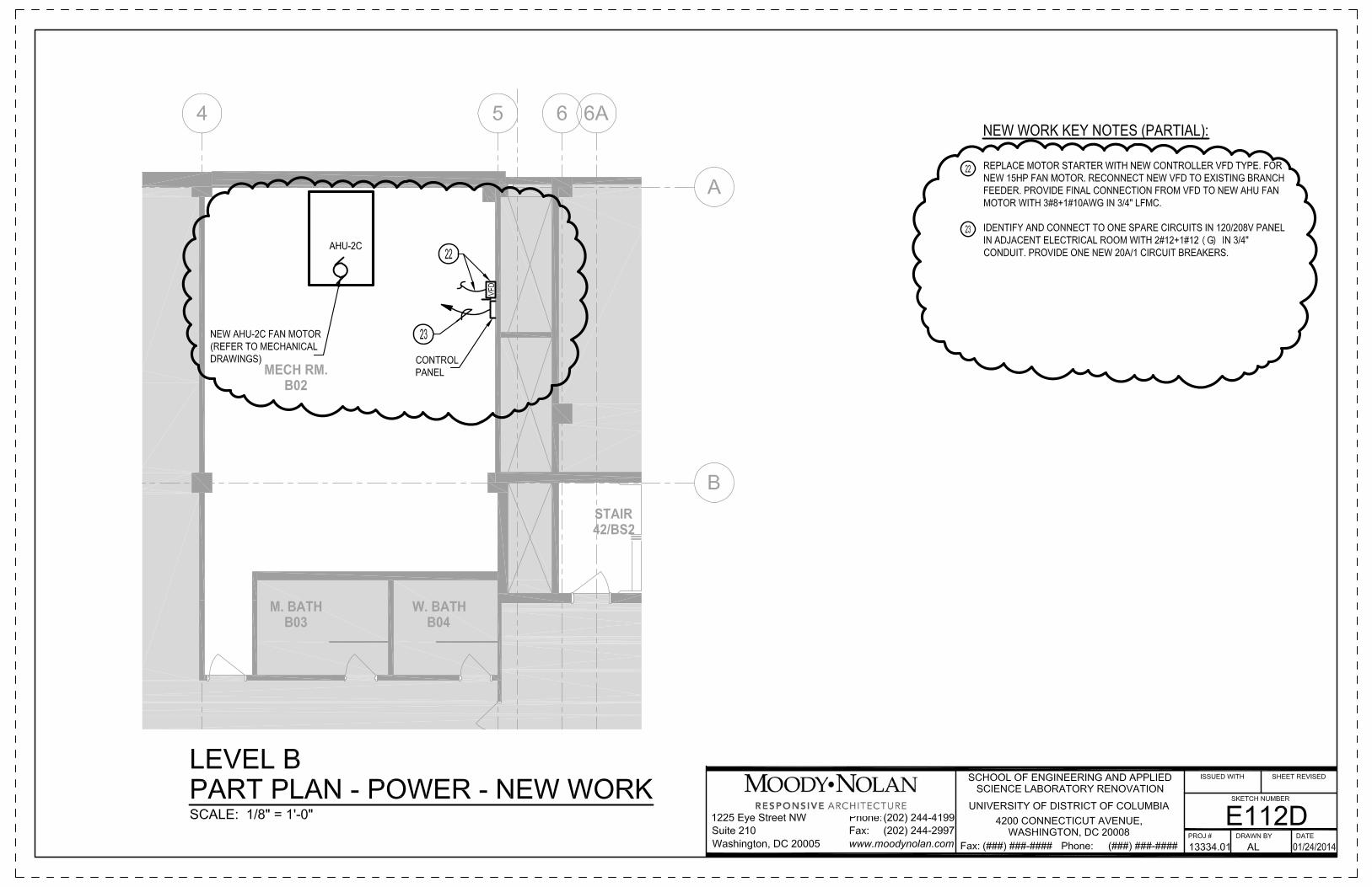
PLAN REVISION: Replace motor starter and AHU‐2C fan motor with new controller VDF type and
new fan motor. (E112D)
ADD SHEET NOTE 22: “Replace motor starter with new controller VFD type for new 15HP fan
motor. Reconnect new VFD to existing branch feeder. Provide final connection from VFD to new
AHU fan motor with 3#8+1#10AWG in ¾” LFMC.” (E112D)
ADD SHEET NOTE 23: “Identify and connect to one spare circuit in 120/208V panel in adjacent
electrical room with 2#12+1#12 (G) in ¾” conduit. Provide one new 20A/1 circuit breaker.”
(E112D)
E‐301
RISER REVISION: Extend demolition of conduit serving panel 2LC‐AS back to disconnect switch
source.
RISER REVISION: Demolish panel 2L2P in 2nd floor electrical room.
E‐302
RISER REVISION: Add new feeder to panel 2LC‐AST extended to power source disconnect.
RISER REVISION: Change capacity of panel 2L1REM from 100A to 225A.
RISER REVISION: Change feeder to panel 2L1REM from #1AWG to 2/0AWG.
RISER REVISION: Add new panel 2L2P 150A to replace the existing one.
ADD SHEET NOTE 18: “Panel 2L2P 225A, 208/120V, 3ph., 4 wire.”
E‐501
LAB EQUIPMENT SCHEDULE: Change junction box and power characteristic to Modular Clean
room to 40A 3‐phase, 4‐wire.
E‐502
EQUIPMENT DISCONNECT AND CONTROL SCHEDULE: Change enclosure type for AHU‐1 to NEMA
1.
EQUIPMENT DISCONNECT AND CONTROL SCHEDULE: Change controller type of HV‐1 from VFD
to full voltage motor starter and change enclosure to NEMA 1.
EQUIPMENT DISCONNECT AND CONTROL SCHEDULE: Change controller type of EF‐1 from full
voltage motor starter to VDF.
EQUIPMENT DISCONNECT AND CONTROL SCHEDULE: Add VFD controller for existing AHU‐2C
E‐504
ADD PANEL SCHEDULE: Add panel schedule of existing panel 2LA‐2 (E504A)
ADD SHEET NOTE 1: “Replace circuit breakers 20A, 120V, 1 pole with new circuit breaker 60A,
208V, 3 pole. Existing circuit breakers will be available after demolition of receptacles in Level A
classroom. See drawing E‐111.” (E504A)
ADD PANEL SCHEDULE: Add panel schedule on new panel 2LP‐2 (E504B)
ADD SHEET NOTE 2: “Existing main feeder and branch circuits to be reconnected to new panel
2L2‐P. Extend existing main feeder and branch circuits as required. Trace and identify existing
branch circuits and provide new updated card directory. Coordinate with owner for circuit
tracing.” (E504B)
E‐505
PANEL 2L1‐REM: Change branch feeder to Modular Clean room from 30A, 2‐pole to 40A, 3‐pole.
Fire Alarm Drawings
FA‐104
PLAN REVISION: Change layout to accommodate new Level C layout
FIRE PROTECTION DRAWINGS
FP‐101
PLAN REVISION: Change sprinkler layout per new Level C layout
FP‐102
PLAN REVISION: Change sprinkler head type in room C12.
HAZARDOUS MATERIALS DRAWINGS
H‐101 NEW SHEET: H‐101 Hazardous Materials
H‐102 NEW SHEET: H‐101 Hazardous Materials
H‐103 NEW SHEET: H‐101 Hazardous Materials
NOTE: The above descriptions are used as a guide to supplement to the drawings.

UDC SEAS Laboratory Renovation CONSTRUCTION DOCUMENTS – 100% ISSUE FOR BID
Project No.: 13334.01 January 14, 2014
CAST-IN-PLACE CONCRETE 03 30 00 - 1
SECTION 03 30 00
CAST-IN-PLACE CONCRETE PART 1 GENERAL 1.01 WORK INCLUDED A. Basic Specification: Perform work of this Section according to ACI 301,
"Specifications for Structural Concrete for Buildings," except as specifically modified herein. Numbers in parentheses (0.00) indicate a related paragraph of ACI 301.
B. Work Included: All cast-in-place concrete work shown on the Drawings and
required by these Specifications. Allow for the installation of cast-in items furnished under other Sections. Install anchor bolts for structural steel. Provide and install grout under steel column base plates and beam bearing areas.
C. Cooperate with other trades who will provide and install items of work (sleeves,
piping, conduit, inserts, etc.) to be cast in the concrete. Place no concrete until all such items are in place.
D. Inspection and testing services required by this Section are to be performed by an
agency retained by the Contractor (1.6.3) subject to the Architect's approval. This includes not only the services required to establish mix designs, but also includes all field sampling and testing required by the Field Quality Control article of this section (1.6.4).
1.02 RELATED SECTIONS
A. Masonry: Section 04 00 00. B. Sealants: Section 07 92 00. 1.03 REFERENCES A. Conform to the provisions of the latest editions of the Standards referenced herein,
except when standards are modified or supplemented herein. B. Standards: The following standards are hereby made a part of this Section and
shall govern where applicable except as otherwise specified. Provide one copy of each at job site for reference. Contractor's supervisory personnel shall be thoroughly familiar with this material as it applies to this project.
1. American Concrete Institute (ACI): a. ACI 301, "Specifications for Structural Concrete for Buildings. b. ACI 305, "Hot Weather Concreting."

UDC SEAS Laboratory Renovation CONSTRUCTION DOCUMENTS – 100% ISSUE FOR BID
Project No.: 13334.01 January 14, 2014
CAST-IN-PLACE CONCRETE 03 30 00 - 2
c. ACI 306, "Cold Weather Concreting." d. ACI 315, "Details and Detailing of Concrete Reinforcement." e. ACI 318, "Building Code Requirements for Reinforced Concrete." f. ACI 347, "Recommended Practice for Concrete Formwork." g. ACI SP-15, "Field Reference Manual." h. ACI SP-44, "Fiber Reinforced Concrete." 2. Concrete Reinforcing Steel Institute (CRSI): a. CRSI P-1, "Placing Reinforcing Bars." C. Reference Standards: Wherever the following abbreviations occur herein, they
shall refer to the corresponding standard: 1. ASTM: American Society for Testing and Materials. 1.04 SUBMITTALS A. Submit for approval the name of the agency proposed for the required inspection
and testing services. If some or all of the required testing is to be performed by personnel not employed by the proposed agency, submit letter from the agency stating that those personnel are qualified to perform the tests.
B. Submit a mix design for each class of concrete required (1.6.3) Submittals to
comply with appropriate methods listed in ACI 301 (4.2.3). Indicate whether mixes have been designed for pumping.
C. Submit shop drawings for all reinforcing. Indicate strength, size and details of all
bar reinforcing and style and specification of all welded wire fabric (3.1.1). 1. Prepare shop drawings in accordance with ACI 315. D. Submit, upon request only, product literature for admixtures and curing compounds
proposed for use. E. Submit reports of all required testing and inspection. F. Submit, on request only, mill test certificate for reinforcing. G. Submit test data for aggregates proposed for use, indicating source and
compliance with specification requirements. Date of test to be no more than 90 days prior to submittal. Resubmit in advance of any proposed change in source.
1.05 QUALITY ASSURANCE A. Layout: Establish and maintain accurate reference points for all concrete surfaces
and elevations. B. Maintain field records of time, date of placing, curing and removal of forms of
concrete in each portion of work. Such records shall be open to inspection, shall

UDC SEAS Laboratory Renovation CONSTRUCTION DOCUMENTS – 100% ISSUE FOR BID
Project No.: 13334.01 January 14, 2014
CAST-IN-PLACE CONCRETE 03 30 00 - 3
be kept until completion of work and turned over to the Architect. 1.06 FIELD REFERENCE MANUAL A. Provide at least one copy of the ACI Field Reference Manual, SP-15, and one copy
of CRSI's "Placing Reinforcing Bars" in the field office at all times (1.3.3). PART 2 PRODUCTS 2.01 MATERIALS A. Cement: Portland cement, ASTM C150, Type I (4.2.1.1). All cement exposed to
public view to be from same mill. B. Water: Potable. C. Aggregates: ASTM C33. 1. Use crushed limestone for coarse aggregate. 2. Coarse Aggregate Size a. Thin Sections: No. 67. b. Stair Pans and Floor Topping: No. 7. c. All Others: No. 57. D. Admixtures (where required or permitted). 1. Water Reducing: "Eucon WR-75" by the EUCLID CHEMICAL COMPANY,
"Pozzolith 200N" by MASTER BUILDERS OR "Plastocrete" by SIKA CHEMICAL CORPORATION. The admixture shall conform to ASTM C4946, Type A and not contain more chloride ions than are present in municipal drinking water. (4.2.1.4).
2. Air-Entraining: ASTM C260 (4.2.1.4). 3. High Range Water Reducing Admixture (Superplasticizer): ASTM C494,
Type F or G and not contain more chloride ions than are present in municipal drinking water. (4.2.1.4). The following are acceptable:
a. Eucon 37 by EUCLID. b. Sikament by SIKA. c. Pozzolith 400-N by MASTER BUILDERS 4. Fly Ash or Pozzolans: ASTM C618 Class F (4.2.1.1.c). Maximum loss on
ignition 3%. 5. Accelerator: Non-corrosive, non-chloride, ASTM C494, Type C or E,
containing no more chlorides than are present in municipal drinking water. The following are acceptable.
a. Accelguard 80 by EUCLID. b. Pozzolith 555 - Accelerator by MASTER BUILDERS. c. Plastocrete 161FL by SIKA. 6. Calcium chloride, thiocyanates or admixtures containing more than 0.05%
ions are NOT permitted (4.2.2.6).
UDC SEAS Laboratory Renovation CONSTRUCTION DOCUMENTS – 100% ISSUE FOR BID
Project No.: 13334.01 January 14, 2014
CAST-IN-PLACE CONCRETE 03 30 00 - 4
7. Upon request only, provide a qualified full-time representative to assure proper use of admixtures.
8. Use of admixtures other than those listed will be permitted only when
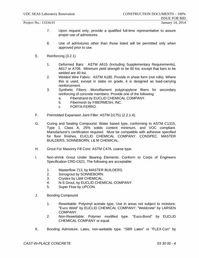
approved prior to use. E. Reinforcing (3.2.1). 1. Deformed Bars: ASTM A615 (Including Supplementary Requirements),
A617 or A706. Minimum yield strength to be 60 ksi, except that bars to be welded are 40 ksi.
2. Welded Wire Fabric: ASTM A185. Provide in sheet form (not rolls). Where this is used, except in slabs on grade, it is designed as load-carrying reinforcement.
3. Synthetic Fibers: Monofilament polypropylene fibers for secondary reinforcing of concrete members. Provide one of the following:
a. Fiberstrand by EUCLID CHEMICAL COMPANY. b. Fibermesh by FIBERMESH, INC. c. FORTA-FERRO. F. Premolded Expansion Joint Filler: ASTM D1751 (2.2.1.4). G. Curing and Sealing Compound: Water based type, conforming to ASTM C1315,
Type 1, Class A, 25% solids content minimum, and VOC compliant. Manufacturer's certification required. Must be compatible with adhesive specified for floor finishes. EUCLID CHEMICAL COMPANY, CONSPEC, MASTER BUILDERS, SONNEBORN, L& M CHEMICAL.
H. Grout For Masonry Fill Core: ASTM C476, coarse type. I. Non-shrink Grout Under Bearing Elements: Conform to Corps of Engineers
Specification CRD-C621. The following are acceptable: 1. Masterflow 713, by MASTER BUILDERS. 2. Sonogrout by SONNEBORN. 3. Crystex by L&M CHEMICAL. 4. N-S Grout, by EUCLID CHEMICAL COMPANY. 5. Super Flow by UPCON. J. Bonding Compound 1. Rewettable: Polyvinyl acetate type. Use in areas not subject to moisture.
"Euco Weld" by EUCLID CHEMICAL COMPANY; "Weldcrete" by LARSEN COMPANY.
2. Non-Rewettable: Polymer modified type. "Euco-Bond" by EUCLID CHEMICAL COMPANY or equal.
K. Bonding Admixture: Latex, non-wettable type. "SBR Latex" or "FLEX-Con" by

UDC SEAS Laboratory Renovation CONSTRUCTION DOCUMENTS – 100% ISSUE FOR BID
Project No.: 13334.01 January 14, 2014
CAST-IN-PLACE CONCRETE 03 30 00 - 5
EUCLID CHEMICAL COMPANY or "Daraweld" by W.R. GRACE. L. Structural Bonding Epoxy Adhesive: Two component 100% solids, 100% reactive
compound suitable for use on dry or damp surfaces. "Euco Epoxy #452MV or #620" by EUCLID CHEMICAL COMPANY or "Sikadur Hi-Mod" by SIKA CHEMICAL CORPORATION.
M. Form Release: Non-staining, rust preventative, guaranteed not to affect bond of
subsequent surface applications to concrete. N. Waterstops: Premolded, flexible, polyvinylchloride. O. Hardener: Dry shake type. Minimum 50 lbs., per 100 square feet. The following
are acceptable. 1. Surflex by EUCLID. 2. Mastercron by MASTER BUILDERS. 3. Harcol by SONNEBORN. 2.02 MIXES A. The following classes of concrete are required (4.2.2.8). Required 28 Day Compressive Maximum Water Air Location Strength, p.s.i. Cement Ratio Content Footings, piers, grade beams, caissons and all other below grade 3000 ---- optional Interior slabs on grade, optional, structural slabs, beams, 3% max. columns, walls 4000 0.50 industrial floors Subjected to freezing and thawing 4000 0.50 4.5 - 7.5% Exterior slabs subjected to deicers 4500 0.50 4.5 - 7.5% Reinforced (bars), subjected to deicers, salt spray or brackish water 5000 0.40 4.5 - 7.5% Exterior topping

UDC SEAS Laboratory Renovation CONSTRUCTION DOCUMENTS – 100% ISSUE FOR BID
Project No.: 13334.01 January 14, 2014
CAST-IN-PLACE CONCRETE 03 30 00 - 6
thin sections 4000 0.50 4.5 - 7.5% Interior stair pans 3000 ---- optional F. Slump 1. Design concrete mixes for a maximum slump of 3 inches for slabs; 4 inches
for all other concrete, unless a superplasticizer is to be used. 2. If a superplasticizer is to be used, design mixes for a slump of 2 - 3 inches
before its addition; maximum slump permitted after its addition is 6 inches for air-entrained concrete, 8 inches for all other concrete.
PART 3 EXECUTION 3.01 SURFACE CONDITIONS A. Verify that excavations are free of water and ice, and of the required dimension,
and have been approved by the Soils Engineer, prior to placing concrete (5.3.1). B. Determine field conditions by actual measurement. C. Notify Architect not less than 24 hours in advance of placing concrete. Place
concrete only when Architect is present, unless this requirement is specifically waived.
3.02 FORMWORK AND REINFORCING A. Footings/Exterior Piers may be cast against earth cuts when soil conditions permit. B. Provide camber of 1/4 inch per 16 feet of span in forms for beams, joists and slabs
which span more than 12 feet. This camber is to compensate for structural deflection after forms are removed, and is to be in addition to the camber required for formwork deflection.
C. Reinforcing 1. Welding of reinforcing is prohibited, except where shown. 2. Use plastic-tipped bar supports for surfaces exposed to view in finished
structure. D. Removal of Forms and Shoring 1. Remove no forms within first 24 hours after placement. 2. When structure is to be reshored, forms may be removed when the
concrete attains 75% of its design strength. 3. Shoring is to remain in place until concrete reaches its design strength. 4. Remove all shoring prior to constructing masonry walls supported by the
structure.

UDC SEAS Laboratory Renovation CONSTRUCTION DOCUMENTS – 100% ISSUE FOR BID
Project No.: 13334.01 January 14, 2014
CAST-IN-PLACE CONCRETE 03 30 00 - 7
3.03 EMBEDDED ITEMS A. Install embedded conduit, pipes, and sleeves subject to the following limitations: 1. Do not embed aluminum without prior approval of coating material. 2. Do not displace reinforcing steel. 3. In slabs limit outside dimension of conduits and pipes to 1/3 member
thickness. Where conduits cross, maintain same minimum concrete cover as for reinforcing bars. For slabs over metal deck, thickness is measured from the top of the metal deck.
4. In columns, limit total area of pipes and conduit to 4% of column area. 5. Maintain center-to-center spacing of at least 3 diameters of conduit or pipe. 3.04 JOINTING A. Interior Slabs on Grade 1. Locate control and construction joints as shown on the Drawings. In the
absence of information on Drawings, locate at openings, walls, columns, grid lines, inside corners and at 12' on center generally. Schedule slab pours and sawcutting operations so that sawing is completed prior to onset of shrinkage cracking (5.3.5).
2. Provide isolation joints at walls (1/4" thick) and at columns (1/2" thick). Where isolation joint will be exposed to view, set top of joint filler below top of slab a distance equal to the filler thickness to receive sealant. Where not exposed to view, set top of filler flush with top of slab.
3. Where joints are exposed to view in the finished building, provide joint sealant.
B. Exterior Slabs on Grade: Locate joints as shown on Drawings. In the absence of
information on Drawings, provide the following: 1. Expansion Joints: Full depth, with 1/2" joint filler where slabs abut vertical
surfaces at intersections of sidewalks, at abrupt changes in width and at a spacing not exceeding 30'.
2. Control Joints: Tooled, 7/8" deep, 4'-0" to 6'-0" o.c. between expansion joints.
3.05 FINISHES A. Schedule of finishes on flatwork is as follows: 1. Troweled Finish: Exposed floors; floors to receive adhesive applied finish
(5.3.4.2.c).
UDC SEAS Laboratory Renovation CONSTRUCTION DOCUMENTS – 100% ISSUE FOR BID
Project No.: 13334.01 January 14, 2014
CAST-IN-PLACE CONCRETE 03 30 00 - 8
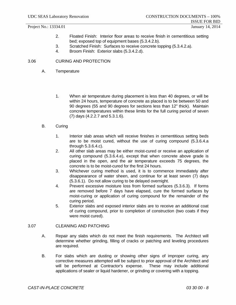
2. Floated Finish: Interior floor areas to receive finish in cementitious setting bed; exposed top of equipment bases (5.3.4.2.b).
3. Scratched Finish: Surfaces to receive concrete topping (5.3.4.2.a). 4. Broom Finish: Exterior slabs (5.3.4.2.d). 3.06 CURING AND PROTECTION A. Temperature 1. When air temperature during placement is less than 40 degrees, or will be
within 24 hours, temperature of concrete as placed is to be between 50 and 90 degrees (55 and 90 degrees for sections less than 12" thick). Maintain concrete temperatures within these limits for the full curing period of seven (7) days (4.2.2.7 and 5.3.1.6).
B. Curing 1. Interior slab areas which will receive finishes in cementitious setting beds
are to be moist cured, without the use of curing compound (5.3.6.4.a through 5.3.6.4.c).
2. All other slab areas may be either moist-cured or receive an application of curing compound (5.3.6.4.e), except that when concrete above grade is placed in the open, and the air temperature exceeds 75 degrees, the concrete is to be moist-cured for the first 24 hours.
3. Whichever curing method is used, it is to commence immediately after disappearance of water sheen, and continue for at least seven (7) days (5.3.6.1). Do not allow curing to be delayed overnight.
4. Prevent excessive moisture loss from formed surfaces (5.3.6.3). If forms are removed before 7 days have elapsed, cure the formed surfaces by moist-curing or application of curing compound for the remainder of the curing period.
5. Exterior slabs and exposed interior slabs are to receive an additional coat of curing compound, prior to completion of construction (two coats if they were moist cured).
3.07 CLEANING AND PATCHING A. Repair any slabs which do not meet the finish requirements. The Architect will
determine whether grinding, filling of cracks or patching and leveling procedures are required.
B. For slabs which are dusting or showing other signs of improper curing, any
corrective measures attempted will be subject to prior approval of the Architect and will be performed at Contractor's expense. These may include additional applications of sealer or liquid hardener, or grinding or covering with a topping.

UDC SEAS Laboratory Renovation CONSTRUCTION DOCUMENTS – 100% ISSUE FOR BID
Project No.: 13334.01 January 14, 2014
CAST-IN-PLACE CONCRETE 03 30 00 - 9
3.08 ACCEPTANCE A. Concrete work with serious honeycombing, form misalignment or other deviation
from Contract requirements is subject to rejection. B. When observations or tests indicate that the Contract requirements have not been
met, the Contractor is to bear the costs of all additional testing and analysis to determine acceptability, and also the cost of removal and replacement, if such is required.
3.09 FIELD QUALITY CONTROL A. Obtain concrete for required tests at point of placement (1.6.4.3). B. For each concrete class, perform one strength test for each 100 yards or fraction
thereof, placed in any one day (1.6.4.2.d). C. Determine slump for each strength test (1.6.4.2.f). D. Determine air content for each strength test of air-entrained concrete (1.6.4.2.h). E. Determine concrete temperature for each strength test (1.6.4.2.g). F. Do not place concrete when slump, air content or temperature varies from
allowable (1.6.8). G. Maintain records of all tests, indicating exact location of the structure represented
by each test.
END OF SECTION

UDC SEAS Laboratory Renovation CONSTRUCTION DOCUMENTS – 100% ISSUE FOR BID
Project No.: 13334.01 January 14, 2014
AUTOMATIC DOOR OPERATORS 08 71 13 - 1
SECTION 08 71 13
AUTOMATIC DOOR OPERATORS PART 1 GENERAL 1.01 DESCRIPTION A. Work Included 1. Automatic door operators, controls and accessories. a. Typical Units: Overhead, surface mounted. 2. Doors specified under Section 08 41 13. 3. Coordination a. Coordinate with finish hardware for compatibility of systems. b. Coordinate required voltages for electric items with voltages
supplied under Division 26. c. Coordinate with Section 08 41 13, Aluminum Entrances, to maintain
single source responsibility for automatic Door Operators and doors.
4. Include necessary materials, devices and labor required for a complete installation.
5. Electrical work limited to internal system wiring and wiring to activating devices and on/off switches.
1.02 RELATED SECTIONS A. Sealants: Section 07 92 00. B. Aluminum Entrances: Section 08 41 13. C. Glass: Section 08 81 00. D. Electrical Work: Division 26. 1. Electrical conduit. 2. Power source. 3. Final connection. 4. Designated electric service. E. Door Access Controls : Section 28 13 00. 1.03 REFERENCES A. American National Standards Institute (ANSI)

UDC SEAS Laboratory Renovation CONSTRUCTION DOCUMENTS – 100% ISSUE FOR BID
Project No.: 13334.01 January 14, 2014
AUTOMATIC DOOR OPERATORS 08 71 13 - 2
1. A156.10: Standard for Power Operated Pedestrian Doors B. Underwriters' Laboratories (UL) 1. UL325: Electric Door, Drapery, Gate, Louver and Window Operators and
Systems. 1.04 SYSTEM DESCRIPTION A. Automatic Door Operators 1. Location/Type: Overhead, surface mounted, heavy duty, electrically
operated. 2. Function: Power assisted opening and closing of door; timing of sequence
and hold-open period adjustable. 3. Action: See drawings for direction of swing, hand, etc. B. Performance Requirements 1. Emergency Exit Doors: Comply with requirements for doors serving as exit
components in means of egress, as certified by the manufacturer for the condition shown.
2. Emergency Break Away: Meet requirements of ANSI A156.10. 3. Service Life: Operators to be capable of operating without failure of any
component, for not less than 300,000 open and close cycles and wind velocities or equivalent inward differential pressures of 20 mph, with normal maintenance as defined in manufacturer's standard operating manual.
4. Time Delay Setting: Operators adjustable to meet Owner's requirements. 5. Load-Bearing Strength (Wind Resistance): Manufacturer's stock system,
adapted to application indicated, tested in accordance with ASTM E330 to withstand at least the following loadings:
a. Uniform pressure of 20 psf inward and outward. 1.05 ELECTRIC COORDINATION A. Power Supplies: Power supplies provided by Division 26 for all electrically operated
hardware including the following: 1. Electric door operators. B. Division 26 Electric Devices: The following electric devices are provided by Division
26: 1. Conduit, relays, transformers. 2. Junction boxes.

UDC SEAS Laboratory Renovation CONSTRUCTION DOCUMENTS – 100% ISSUE FOR BID
Project No.: 13334.01 January 14, 2014
AUTOMATIC DOOR OPERATORS 08 71 13 - 3
C. Voltages and Operation Requirements 1. Operator: 120 VAC. 2. Verify all voltages with Division 16 upon Contract award. 1.06 SUBMITTALS A. Submit in accordance with the requirements of the General Conditions and Section
01 33 23. B. Shop Drawings: Include complete elevations of the system; details and methods of
anchorage; details of construction; finishes; methods of assembly; location and installation of hardware and reinforcement for same; size, shape and thickness of materials; joints and connections; details of joining other work. Show locations of all components.
C. Product Data: Complete product description. Include all electrical requirements and
complete information required for electrical coordination. D. Maintenance Data: Furnish written instructions to Owner describing recommended
materials and methods for proper maintenance of opener system. 1. Provide adjusting wrenches and other tools necessary for door adjustment
and maintenance. 2. Tag tools for positive identification and deliver to Owner prior to acceptance
of work. E. Maintenance Agreement 1. Installer shall provide continuing maintenance proposal to Owner for his
consideration, in the form of a standard yearly maintenance agreement, starting on date construction contract maintenance requirements are concluded. State services, obligations and terms for agreement period, and for renewal options. Charges for this agreement shall not be part of the base contract price.
1.07 QUALITY ASSURANCE A. Subcontract: Subcontract automatic door work to aluminum entrance contractor for
proper coordination and single source responsibility where systems abut or connect to one another.
B. Standards: Provide automatic door operators complying with ANSI A156.10 and UL
Standard 325. C. Qualifications

UDC SEAS Laboratory Renovation CONSTRUCTION DOCUMENTS – 100% ISSUE FOR BID
Project No.: 13334.01 January 14, 2014
AUTOMATIC DOOR OPERATORS 08 71 13 - 4
1. Manufacturer: Provide units produced by a firm with not less than 5 years successful experience in the fabrication of automatic door equipment of the type required for this project.
2. Installer: Engage an installer who is an authorized representative of the automatic door equipment manufacturer for both the installation and the maintenance of the type of units required for this project.
a. Minimum Experience: Not less than 3 years experience in the
installation and service of automatic door equipment of the same manufacturer.
b. Maintenance Proximity: Not more than 1 hour normal travel time from Installer's place of business to project site.
1.07 PRODUCT DELIVERY, STORAGE AND HANDLING A. Store materials at job site so as to prevent damage to members or assemblies, and
protect from corrosion or deterioration. 1.08 WARRANTY A. Contractor(s): Provide a 2 year guarantee on all systems. 1. Warrant systems free of defects due to faulty materials and workmanship. 2. Include repair and replacement of defective materials and components at
no additional cost to the Owner. PART 2 PRODUCTS 2.01 MANUFACTURERS A. Provide conforming products from one of the following: 1. BESAM 2. STANLEY 3. DOR-O-MATIC 2.02 MATERIALS A. Exposed Metal 1. Aluminum Extrusions and Aluminum Sheet a. Compatible with specified finish. 2. Provide aluminum alloy and temper for each shape, as recommended by
manufacturer and processor to comply with the requirements of performance, fabrication, application of finish, and control of color.
UDC SEAS Laboratory Renovation CONSTRUCTION DOCUMENTS – 100% ISSUE FOR BID
Project No.: 13334.01 January 14, 2014
AUTOMATIC DOOR OPERATORS 08 71 13 - 5
B. Aluminum Thickness 1. Section thickness to meet design requirements. 2. Moldings, Trim and Glass Stops: 0.05 inch minimum. C. Concealed Metals: Manufacturer's standard, suitable for application. D. Steel Reinforcements and Brackets: Manufacturer's standard units with 2.0 ounce
hot-dip galvanized coating, ASTM A653. Applied after fabrication. E. Fasteners: Aluminum, non-magnetic stainless steel, or other noncorrosive metal
compatible with the items being fastened. For exposed fasteners, provide Phillips flat-head screws with finish matching the item fastened.
F. Sealants and Gaskets: Manufacturer's standard. G. Bituminous Coatings: Cold applied asphalt mastic, SSPC-PAINT 12. 2.03 AUTOMATIC DOOR OPENER A. Specification based on electric swing door system by BESAM, Model 450,
overhead, surface mounted. See Part 1, Performance Requirements. B. Operator Location: Controls and connecting hardware to mount above door frame;
provide with removable aluminum access cover in front. 1. Housing: Nominal 6" x 6" with finished end caps; See Materials
hereinbefore. Minimum aluminum thickness 0.146 inch. C. Operator Function: Manufacturer's standard electrical unit, powered in the opening
cycle, spring return in the closing cycle and with speed control to provide checking in both cycles.
1. Provide for manual operation when power is off, and provide emergency
release for manual swing-out action of doors that are indicated to function as exits.
2. Equip units with hold-open switch, arranged to hold door open without the continued use of power.
D. Operator Action: As indicated by door swing on drawings (swing-in, swing-out,
double swing, pairs, etc.). E. Electrical Control: Self-contained unit including necessary transformers, relays,
rectifiers, and other electronic components for proper operation and switching of power operator.
1. Relays: Plug-in type for individual replacement. 2. Connecting Harnesses: Provide with interlocking plugs.

UDC SEAS Laboratory Renovation CONSTRUCTION DOCUMENTS – 100% ISSUE FOR BID
Project No.: 13334.01 January 14, 2014
AUTOMATIC DOOR OPERATORS 08 71 13 - 6
3. Provide control with adjustable time delay module of 0-60 seconds. F. Hardware 1. Manufacturer's standard arm and track device or direct connection to center
pivots. 2. Keyed Switch: Manufacturer's standard key operated on/off switch; cylinder
furnished under Section 08 71 00, Finish Hardware. 2.04 ACTUATING CONTROLS A. Push Button: Provide 6" diameter stainless steel push button switch with
handicapped insignia. Locate interior control button on wall as indicated. 2.05 HARDWARE A. Provide hardware necessary for complete installation. B. Automatic door opener supplier to coordinate all door preparation for hardware
scheduled under Section 08 41 13, Aluminum Entrances. 2.06 ACCESSORIES A. Marking: Provide caution decals on automatic doors in conformance with ANSI
A156.10. B. Miscellaneous: As required for complete installation. 2.07 FABRICATION A. General 1. Sizes and Profiles: Required sizes for door and frame units, including
profile requirements, as specified and as indicated on drawings. 2. Welding: Comply with AWS recommendations to avoid discoloration at
welds; grind exposed welds smooth and restore mechanical finish. 3. Conceal fasteners where possible. 4. Maintain continuity of line and accurate relation of planes and angles.
Provide secure attachment and support at mechanical joints, with hairline fit of contacting members.
5. Reinforce the work as necessary for performance requirements, and for support to the structure. Separate dissimilar metals with bituminous paint or preformed separators. Separate metal surfaces at moving joints with non-metallic separators to prevent "freeze-up" of joints.
6. Weatherstripping: Where exterior door stiles or head rails do not close
UDC SEAS Laboratory Renovation CONSTRUCTION DOCUMENTS – 100% ISSUE FOR BID
Project No.: 13334.01 January 14, 2014
AUTOMATIC DOOR OPERATORS 08 71 13 - 7
against fixed stops equipped with weatherstripping, provide weatherstripping, retained in an adjustable strip in a mortise centered in the edge of the door.
B. Aluminum Door and Sidelight Framing: Provided under Section 08 41 13,
Aluminum Entrances. See Part 1, Description, for coordination with other products. PART 3 EXECUTION 3.01 EXAMINATION A. Examine substrates to which work of this Section applies. No work shall be
installed until corrections to substrates have been performed by trades involved. 3.02 INSTALLATION A. Install in accordance with manufacturer's instructions and recommendations and in
compliance with referenced standards. Members shall be level, square, plumb, at proper elevations and in alignment with other work. Attach and secure to structure as required to assure stability of system.
B. Provide wiring from activating devices, controls, and remote on/off switches in
conduit provided under Division 26. C. All units to be free and smoothly operating without binding or rough spots; adjust as
required and/or replace improperly functioning units. D. After repeated operation of completed installation equivalent to three days use by
normal traffic (100 to 300 cycles), readjust door operators and controls for optimum operating conditions and safety. Lubricate operating equipment and clean exposed surfaces.
E. Provide protective measures and other precautions required to ensure that
automatic entrance doors will be without damage or deterioration, other than normal weathering, at time of substantial completion.
END OF SECTION

UDC SEAS Laboratory Renovation CONSTRUCTION DOCUMENTS – 100% ISSUE FOR BID
Project No.: 13334.01 January 14, 2014
ENTRANCE FLOOR GRIDS 12 48 23 - 1
SECTION 12 48 23
ENTRANCE FLOOR GRIDS PART 1 GENERAL 1.01 WORK INCLUDED A. Provide recessed entrance grid mats and frames. 1.02 SUBMITTALS A. Shop Drawings: Submit product data and layout drawings in accordance with the
General Conditions. Provide data on both mat and frame, including dimensioned plan of frame recess.
B. Samples: Provide 2 samples of entrance floor mat 4" x 8"; and 2 color charts of
manufacturer's standard colors. 1.03 JOB CONDITIONS A. Coordination: Coordinate concrete slab placement with installation of recessed
frame. Verify location, shape and size of mat. PART 2 PRODUCTS 2.01 MATERIALS
A. Entrance Floor Mat: BALCO, SSMR-118 Type 304 Stainless Steel Entrance Grate or equal by MM SYSTEMS CORPORATION CONSTRUCTION SPECIALTIES, MM SYSTEMS CORPORATION; ARDEN ENTRANCE MATS or REESE ENTERPRISES. Including the following:
1. Material: Mill Finish Stainless Steel. 2. Description: Recessed mat consisting of interlocking tread rails, frame
(mitered and positive locked), and continuous resilient bearing cushions. 3. Construction: Series of tread rails continuously hinged together running
counter to traffic flow. Frames and tread rails within 1 1/4" (nominal) recess depth.
4. Size: As indicated on drawings. PART 3 EXECUTION

UDC SEAS Laboratory Renovation CONSTRUCTION DOCUMENTS – 100% ISSUE FOR BID
Project No.: 13334.01 January 14, 2014
ENTRANCE FLOOR GRIDS 12 48 23 - 2
3.01 INSTALLATION A. Verify mat recess dimensions before fabrication of mat. Place mat loose in
applicable recess. Coordinate installation of recessed frame with floor slab pour. B. Install mat in locations indicated on drawings per manufacturer's instructions.
END OF SECTION

UDC SEAS Laboratory Renovation CONSTRUCTION DOCUMENTS – 100% ISSUE FOR BID
Project No.: 13334.01 January 14, 2014
INTERIOR SIGNAGE 10 14 10 - 1
SECTION 10 14 10
INTERIOR SIGNAGE PART 1 GENERAL 1.01 WORK INCLUDED A. Work includes: 1. Room numbers/Room identification 2. Restrooms a. Wheel Chair Accessible b. Non-Accessible 3. Stairwell identification. 4. Floor identification (stairwell). 5. Directional/Informational signs. 6. Elevator door jamb plate (floor numbering). 7. Emergency escape directories. 8. Posted occupancy limit. 9. Elevator fire emergency plaque. B. All signs which identify permanent facilities/accommodations shall be tactile and
braille and limited minimally to room numbers, restrooms, stairways, floor identification, elevators and room names as deemed appropriate by the Owner.
1.02 SUBMITTALS A. Shop Drawings: Submit manufacturer's product data, where applicable, and
complete drawings showing all identifying devices and installation details in accordance with the requirements of the General Conditions.
B. Samples: Submit samples for materials, finishes, colors, letter styles, etc., as
required for selection and approval by Architect prior to fabrication of identifying devices.
C. Final signage schedule must be approved by Owner prior to fabrication. Submittal
to Owner should be made through the Architect. 1.03 QUALITY ASSURANCE A. Signage Standards: Conform to the Americans with Disabilities Act (ADA)
Standards where applicable and to the extent as indicated.

UDC SEAS Laboratory Renovation CONSTRUCTION DOCUMENTS – 100% ISSUE FOR BID
Project No.: 13334.01 January 14, 2014
INTERIOR SIGNAGE 10 14 10 - 2
B. Acceptable Manufacturers: All units are to be custom fabricated; manufacturer's products meeting the specifications will be acceptable. Manufacturers must be regularly engaged in fabrication and installation of signage units and related identifying devices.
1. Fabricator shall make at least one visit to the site before production begins
to review all sign locations and installation conditions with Architect and Owner's representative.
2. Fabricator must review all dimensional changes with Architect. C. Approvals: All identifying devices shall be approved at the fabricator's shop by the
Architect prior to shipment and installation. D. Spelling and Braille Accuracy: Responsibility of sign manufacturer. E. The Owner has the right to renumber the room numbers during construction.
Manufacturer must not begin fabrication of room number plates until room numbers have been approved by the Owner, in writing, through the Architect.
F. Room identifications will be provided to the Contractor by the Owner during
construction. 1.04 DELIVERY, STORAGE AND HANDLING A. Deliver materials in manufacturer's original shipping cartons with seals unbroken. B. Protect materials from physical damage. C. Store materials in clean, dry area. D. Inspect all materials prior to installation to assure proper function and condition of
all items. PART 2 PRODUCTS 2.01 GENERAL REQUIREMENTS A. Locations, Quantities, Graphics and Copy: As indicated on drawings and/or
specified (scheduled) herein. 2.02 MATERIALS A. Plates: High pressure phenolic "ES" plastic; scratch resistant, non-static,
thermoset, rated self-extinguishing. 1. Colors: As selected by Architect. 2. Thickness: 3/32" for ADA plates; 1/16" for non-raised copy (flat) plates.

UDC SEAS Laboratory Renovation CONSTRUCTION DOCUMENTS – 100% ISSUE FOR BID
Project No.: 13334.01 January 14, 2014
INTERIOR SIGNAGE 10 14 10 - 3
B. Changeable Copy: Provide 3/32" thick plastic back-up plate laminated to back of
face plate to create slot for removable nameplates. C. Provide an integral method to create tactile and Braille signs; producing a unitary
component. Glued on or laminated letters or Braille cells are not acceptable. 2.03 DESIGN GUIDELINES A. Plate Shape: Square cornered; do not bevel edges. B. Letter Style 1. ADA Signs: Helvetica medium, all capital letters. 2. All Other Signs: Helvetica medium, mixed upper and lower case. C. Tactile Letters and Braille: Grade II braille; raised 1/32" above background surface.
Provide Braille dome topped same color as background. Sign manufacturer shall be responsible for verifying accuracy of spelling, both tactile and Braille.
D. Letter Size 1. Tactile Signs: Minimum letter size is 5/8" for capital letters. Room numbers
to be 1 1/4". 2. Non-tactile Signs: Between 3/8" and 1" capital letter height. Larger letters
are permitted on directional signs or on signs where reading distance is greater than 15'-0".
3. Overhead Signs: Minimum 3" copy. Mixed upper and lower case is permissible. Non-tactile is permissible.
2.04 METHOD OF MANUFACTURING A. Tactile Signs: Relief engraved plates. B. Non-Tactile Signs: Routed engraved. 2.05 SIGNS REQUIRED FOR TACTILE/BRAILLE A. Room Numbers/Room Identification: 1. Size determined by copy requirements, laid out flush left with 3/4" margin
on left, room name in 5/8" caps with Braille directly below type copy, all flush left.
B. Restrooms - Wheel Chair Accessible: Approximately 9” wide x 9” high plate with
1" capital letters (MEN or WOMEN), centered on the plate with Braille directly below the copy. Provide a routed engraved wheel chair access symbol and a universal man or woman symbol located above the word. No border.
UDC SEAS Laboratory Renovation CONSTRUCTION DOCUMENTS – 100% ISSUE FOR BID
Project No.: 13334.01 January 14, 2014
INTERIOR SIGNAGE 10 14 10 - 4
C. Stairwell Identification: 9" x 9" plate with 1" capital letters laid out flush left with 3/4"
margin on left. Braille directly below the type copy. D. Floor Identification - Inside Stairwells: 9" x 9" plate with 1" capital letters (1st
FLOOR, 2nd FLOOR, etc.) laid out flush left with 3/4" margin on left . Braille directly below the type copy.
E. Directional/Informational Signs: Wall mounted; non-tactile; in upper and lower
case. Letter height shall be at least 1" cap height for directional signs. Letter sizes for informational signs may be less than 1".
F. Elevator Door Jamb Plate: 3-3/4" x 3-3/4" plate with 2" numerals centered
horizontally on plate with Braille centered directly below numerals. 2.06 SIGNS REQUIRED FOR NON-TACTILE/BRAILLE SIGNAGE A. Plate Shape: Square cornered; do not bevel edges. B. Plate Heights 1. 2-1/4" for one line of copy. 2. 3-3/4" for two lines of copy. 3. 5-1/4" for three lines of copy. C. Changeable Copy Plates 1. Height: Same as in "2.05 A" above. 2. Length: VARIES 3. Face openings of slot: 1" high with 3/4" margin at ends and bottom. 4. Allow 1/2" vertically between slot openings. 5. Slots behind openings: Allow for 1-1/4" wide x 1/16" thick blank changeable
copy strips supplied by the Contractor for future engraving by Owner. 6. Tactile room numbers with Braille may appear on the face of the sign
frame. 2.07 EMERGENCY ESCAPE DIRECTORY A. Description: 18" x 12". Extruded aluminum "F" frame with anodized medium bronze
finish and non-glare acrylic face. Provide with rigid masonite backing. B. Copy: Color screen printed removable graphic of floor plan showing escape route
from installed location. Locate at elevators and stair doors at each floor, and at building main entrance.
2.08 POSTED OCCUPANCY LIMIT
UDC SEAS Laboratory Renovation CONSTRUCTION DOCUMENTS – 100% ISSUE FOR BID
Project No.: 13334.01 January 14, 2014
INTERIOR SIGNAGE 10 14 10 - 5
A. Posted Occupancy Limit: Provide sign reading, "Maximum Occupants Permitted This Space". Provide signage in accordance with OBC 1004 “Posting of Occupant Load”. Locate signs as indicated on drawins (sign type L)
2.10 ELEVATOR FIRE EMERGENCY PLAQUE A. Description: Approximately 9" x 9". Text to read, "In Case of Fire Use Stairs" in 1"
letters with Braille centered below. Graphics to include international wheelchair and stair symbols.
UDC SEAS Laboratory Renovation CONSTRUCTION DOCUMENTS – 100% ISSUE FOR BID
Project No.: 13334.01 January 14, 2014
INTERIOR SIGNAGE 10 14 10 - 6
2.11 COPY POSITION A. Lines of copy laid out flush left with a margin of 3/4" along the left edge of plate.
Exceptions are small room numbers, restrooms and stairways shall be centered on the plate.
B. Left hand, right hand and bottom margins are 3/4". Vertical spacing measured
between lower case letters is 3/4". Overall width and height of a plate is achieved with multiples of 3/4".
C. Locate directional arrows in upper left hand corner of plate. Arrows count as one
line of copy. PART 3 EXECUTION 3.01 INSTALLATION A. Mount signs plumb and level. B. Mount all identification devices with 3/4" foam tape on all four edges. 3.02 SIGNAGE SCHEDULE A. Provide the following Sign Plates 1. Room Identification Signs: As noted on drawings as sign types E.3 or J. 2. Women, combined with room number and handicap symbol and
international symbol, as applicable, at each restroom. As noted on drawings as sign type E.2W
3. Men, combined with room number and handicap symbol and international symbol, as applicable, at each restroom. As noted on drawings as sign type E.2M
B. Stairwell Identification: Provide at all stair doors as noted on drawings as sign type
E.1 C. Floor Identification: Provide inside stairwell at all stair doors as noted on drawings
as sign type N. D. Elevator Fire Emergency Plaque: Provide at each elevator stop as noted on
drawings as sign type D.2. F. Elevator Door Jamb Plates: Two plates required per elevator door, one on each
side of the jamb. E. Emergency Escape Directory: As noted on drawings as sign type D.1.
UDC SEAS Laboratory Renovation CONSTRUCTION DOCUMENTS – 100% ISSUE FOR BID
Project No.: 13334.01 January 14, 2014
INTERIOR SIGNAGE 10 14 10 - 7
UDC SEAS Laboratory Renovation CONSTRUCTION DOCUMENTS – 100% ISSUE FOR BID
Project No.: 13334.01 January 14, 2014
INTERIOR SIGNAGE 10 14 10 - 8
F. Directional/Informational Signs: For bidding purposes, provide one per stair door on each floor and an additional one per lobby and vestibules on the entry floor. Each sign will contain 25 symbols/characters arranged in two lines. Locate as directed by Architect. As noted on drawings as sign type B.
G. Posted Occupancy Limit: As noted on drawings as sign type L H. Sign Locations 1. Single Doors: Locate signs on the wall next to the latch side of the door, 1"
from the outside edge of the door frame and with the top edge of the uppermost sign 61-1/2" A.F.F.
2. Pairs of Doors: Locate signs as specified above for single doors, except Architect will direct in field if sign occurs on right or left jamb of opening.
3. Doors with Borrowed Lights: Locate as directed by Architect. 3.03 CLEAN UP A. After completion of work remove all debris and tools from the premises, clean all
adhesive spatter and run-over from finished surfaces and wash all plated clean of fingermarks and soil. Polish sign surfaces with a soft cotton rag.
END OF SECTION

UDC SEAS Laboratory Renovation CONSTRUCTION DOCUMENTS – 100% ISSUE FOR BID
Project No.: 13334.01 January 14, 2014
MODULAR INDOOR CENTRAL-STATION AIR-HANDLING UNITS 237313 - 1
SECTION 237313 - MODULAR INDOOR CENTRAL-STATION AIR-HANDLING UNITS
PART 1 - GENERAL
1.1 RELATED DOCUMENTS
A. Drawings and general provisions of the Contract, including General and Supplementary Conditions and Division 01 Specification Sections, apply to this Section.
1.2 SUMMARY
A. Section Includes:
1. Constant-air-volume, single-zone air-handling units. 2. Variable-air-volume, single-zone air-handling units.
1.3 PERFORMANCE REQUIREMENTS
A. Delegated Design: Design vibration isolation and seismic-restraint details, including comprehensive engineering analysis by a qualified professional engineer, using performance requirements and design criteria indicated.
B. Structural Performance: Casing panels shall be self-supporting and capable of withstanding 133 percent of internal static pressures indicated, without panel joints exceeding a deflection of L/100 where "L" is the unsupported span length within completed casings.
1.4 ACTION SUBMITTALS
A. Product Data: For each air-handling unit indicated.
1. Unit dimensions and weight. 2. Cabinet material, metal thickness, finishes, insulation, and accessories. 3. Fans:
a. Certified fan-performance curves with system operating conditions indicated. b. Certified fan-sound power ratings. c. Fan construction and accessories. d. Motor ratings, electrical characteristics, and motor accessories.
4. Certified coil-performance ratings with system operating conditions indicated. 5. Dampers, including housings, linkages, and operators. 6. Filters with performance characteristics.
UDC SEAS Laboratory Renovation CONSTRUCTION DOCUMENTS – 100% ISSUE FOR BID
Project No.: 13334.01 January 14, 2014
MODULAR INDOOR CENTRAL-STATION AIR-HANDLING UNITS 237313 - 2
1.5 INFORMATIONAL SUBMITTALS
A. Coordination Drawings: Floor plans and other details, drawn to scale, on which the following items are shown and coordinated with each other, using input from installers of the items involved:
1. Mechanical-room layout and relationships between components and adjacent structural and mechanical elements.
2. Support location, type, and weight. 3. Field measurements.
B. Source quality-control reports.
C. Field quality-control reports.
1.6 CLOSEOUT SUBMITTALS
A. Operation and Maintenance Data: For air-handling units to include in emergency, operation, and maintenance manuals.
1.7 MAINTENANCE MATERIAL SUBMITTALS
A. Furnish extra materials that match products installed and that are packaged with protective covering for storage and identified with labels describing contents.
1. Filters: One set(s) for each air-handling unit. 2. Gaskets: One set(s) for each access door. 3. Fan Belts: One set(s) for each air-handling unit fan.
1.8 QUALITY ASSURANCE
A. Electrical Components, Devices, and Accessories: Listed and labeled as defined in NFPA 70, by a qualified testing agency, and marked for intended location and application.
B. NFPA Compliance: Comply with NFPA 90A for design, fabrication, and installation of air-handling units and components.
C. ARI Certification: Air-handling units and their components shall be factory tested according to ARI 430, "Central-Station Air-Handling Units," and shall be listed and labeled by ARI.
D. ASHRAE Compliance: Applicable requirements in ASHRAE 62.1, Section 5 - "Systems and Equipment" and Section 7 - "Construction and Startup."
E. ASHRAE/IESNA 90.1 Compliance: Applicable requirements in ASHRAE/IESNA 90.1, Section 6 - "Heating, Ventilating, and Air-Conditioning."
F. Comply with NFPA 70.

UDC SEAS Laboratory Renovation CONSTRUCTION DOCUMENTS – 100% ISSUE FOR BID
Project No.: 13334.01 January 14, 2014
MODULAR INDOOR CENTRAL-STATION AIR-HANDLING UNITS 237313 - 3
1.9 COORDINATION
A. Coordinate sizes and locations of concrete bases with actual equipment provided.
B. Coordinate sizes and locations of structural-steel support members, if any, with actual equipment provided.
PART 2 - PRODUCTS
2.1 MANUFACTURERS
A. Manufacturers: Subject to compliance with requirements, available manufacturers offering products that may be incorporated into the Work include, but are not limited to, the following:
1. Carrier Corporation; a member of the United Technologies Corporation Family. 2. Coil Company, LLC. 3. McQuay International 4. Trane; American Standard Inc. 5. USA Coil & Air. 6. Johnson Controls
2.2 UNIT CASINGS
A. General Fabrication Requirements for Casings:
1. Forming: Form walls, roofs, and floors with at least two breaks at each joint. 2. Casing Joints: Sheet metal screws or pop rivets. 3. Sealing: Seal all joints with water-resistant sealant. 4. Factory Finish for Steel Casings: Apply manufacturer's standard primer immediately after
cleaning and pretreating. 5. Factory Finish for Steel Casings: Immediately after cleaning and pretreating, apply
manufacturer's standard two-coat, baked-on enamel finish, consisting of prime coat and thermosetting topcoat.
6. Casing Coating: Powder-baked enamel. 7. Airstream Surfaces: Surfaces in contact with the airstream shall comply with
requirements in ASHRAE 62.1.
B. Casing Insulation and Adhesive:
1. Materials: ASTM C 1071, Type I. 2. Location and Application: Factory applied with adhesive and mechanical fasteners to the
internal surface of section panels downstream from, and including, the cooling-coil section.
a. Liner Adhesive: Comply with ASTM C 916, Type I. b. Mechanical Fasteners: Galvanized steel, suitable for adhesive attachment,
mechanical attachment, or welding attachment to duct without damaging liner

UDC SEAS Laboratory Renovation CONSTRUCTION DOCUMENTS – 100% ISSUE FOR BID
Project No.: 13334.01 January 14, 2014
MODULAR INDOOR CENTRAL-STATION AIR-HANDLING UNITS 237313 - 4
when applied as recommended by manufacturer and without causing leakage in cabinet.
c. Liner materials applied in this location shall have air-stream surface coated with a temperature-resistant coating or faced with a plain or coated fibrous mat or fabric depending on service-air velocity.
3. Location and Application: Encased between outside and inside casing.
C. Inspection and Access Panels and Access Doors:
1. Panel and Door Fabrication: Formed and reinforced, single- or double-wall and insulated panels of same materials and thicknesses as casing.
2. Inspection and Access Panels:
a. Fasteners: Two or more camlock type for panel lift-out operation. Arrangement shall allow panels to be opened against air-pressure differential.
b. Gasket: Neoprene, applied around entire perimeters of panel frames. c. Size: Large enough to allow inspection and maintenance of air-handling unit's
internal components.
3. Access Doors:
a. Hinges: A minimum of two ball-bearing hinges or stainless-steel piano hinge and two wedge-lever-type latches, operable from inside and outside. Arrange doors to be opened against air-pressure differential.
b. Gasket: Neoprene, applied around entire perimeters of panel frames. c. Size: At least 24 inches wide by full height of unit casing up to a maximum height
of 60 inches
4. Locations and Applications:
a. Fan Section: Doors. b. Access Section: Doors. c. Coil Section: Inspection and access panel. d. Damper Section: Doors. e. Filter Section: Doors large enough to allow periodic removal and installation of
filters. f. Mixing Section: Doors. g. Humidifier Section: Doors.
D. Condensate Drain Pans:
1. Fabricated with one percent slope in at least two planes to collect condensate from cooling coils (including coil piping connections, coil headers, and return bends) and from humidifiers and to direct water toward drain connection.
a. Length: Extend drain pan downstream from leaving face to comply with ASHRAE 62.
b. Depth: A minimum of 2 inches deep.
UDC SEAS Laboratory Renovation CONSTRUCTION DOCUMENTS – 100% ISSUE FOR BID
Project No.: 13334.01 January 14, 2014
MODULAR INDOOR CENTRAL-STATION AIR-HANDLING UNITS 237313 - 5
2. Integral part of floor plating. 3. Single-wall, stainless-steel sheet. 4. Drain Connection: Located at lowest point of pan and sized to prevent overflow.
Terminate with threaded nipple on one end of pan.
a. Minimum Connection Size: NPS 1
E. Air-Handling-Unit Mounting Frame: Formed galvanized-steel channel or structural channel supports, designed for low deflection, welded with integral lifting lugs.
2.3 FAN, DRIVE, AND MOTOR SECTION
A. Fan and Drive Assemblies: Statically and dynamically balanced and designed for continuous operation at maximum-rated fan speed and motor horsepower.
1. Shafts: Designed for continuous operation at maximum-rated fan speed and motor horsepower, and with field-adjustable alignment.
a. Turned, ground, and polished hot-rolled steel with keyway. Ship with a protective coating of lubricating oil.
b. Designed to operate at no more than 70 percent of first critical speed at top of fan's speed range.
B. Centrifugal Fan Housings: Formed- and reinforced-steel panels to form curved scroll housings with shaped cutoff and spun-metal inlet bell.
1. Bracing: Steel angle or channel supports for mounting and supporting fan scroll, wheel, motor, and accessories.
2. Horizontal-Flanged, Split Housing: Bolted construction. 3. Housing for Supply Fan: Attach housing to fan-section casing with metal-edged flexible
duct connector. 4. Flexible Connector: Factory fabricated with a fabric strip 5-3/4 inches wide attached to 2
strips of 2-3/4-inch- wide, 0.028-inch- thick, galvanized-steel sheet or 0.032-inch- thick aluminum sheets; select metal compatible with casing.
a. Flexible Connector Fabric: Glass fabric, double coated with neoprene. Fabrics, coatings, and adhesives shall comply with UL 181, Class 1.
1) Fabric Minimum Weight: 26 oz./sq. yd.. 2) Fabric Tensile Strength: 480 lbf/inch in the warp and 360 lbf/inch in the
filling. 3) Fabric Service Temperature: Minus 40 to plus 200 deg F.
C. Airfoil, Centrifugal Fan Wheels: Smooth-curved inlet flange, backplate, and hollow die-formed airfoil-shaped blades continuously welded at tip flange and backplate; cast-iron or cast-steel hub riveted to backplate and fastened to shaft with set screws.
D. Fan Shaft Bearings:

UDC SEAS Laboratory Renovation CONSTRUCTION DOCUMENTS – 100% ISSUE FOR BID
Project No.: 13334.01 January 14, 2014
MODULAR INDOOR CENTRAL-STATION AIR-HANDLING UNITS 237313 - 6
1. Prelubricated and Sealed, Ball Bearings: Self-aligning, pillow-block type with a rated life of 120,000 hours according to ABMA 9.
2. Grease-Lubricated, Tapered-Roller Bearings: Self-aligning, pillow-block type with double-locking collars and 2-piece, cast-iron housing with grease lines extended to outside unit and a rated life of 120,000 hours according to ABMA 11.
E. Belt Drives: Factory mounted, with adjustable alignment and belt tensioning, and with 1.5 service factor based on fan motor.
1. Pulleys: Cast iron or cast steel with split, tapered bushing; dynamically balanced at factory.
2. Motor Pulleys: Adjustable pitch for use with 5-hp motors and smaller; fixed pitch for use with motors larger than 5hp. Select pulley size so pitch adjustment is at the middle of adjustment range at fan design conditions.
3. Belts: Oil resistant, nonsparking, and nonstatic; in matched sets for multiple-belt drives. 4. Belt Guards: Comply with requirements specified by OSHA and fabricate according to
SMACNA's "HVAC Duct Construction Standards"; 0.1046-inch- thick, 3/4-inch diamond-mesh wire screen, welded to steel angle frame; prime coated.
F. Variable-Inlet Vanes: Steel, with blades supported at both ends with permanently lubricated bearings. Variable mechanism terminating in single lever for connection to control actuator with connecting shaft for second set of variable inlet vanes on double-width fans.
G. Internal Vibration Isolation: Fans shall be factory mounted with manufacturer's standard vibration isolation mounting devices having a minimum static deflection of 1 inch.
H. Motor: Comply with NEMA designation, temperature rating, service factor, enclosure type, and efficiency requirements for motors specified in Section 230513 "Common Motor Requirements for HVAC Equipment."
1. Enclosure Type: Totally enclosed, fan cooled. 2. NEMA Premium (TM) efficient motors as defined in NEMA MG 1. 3. Motor Sizes: Minimum size as indicated. If not indicated, large enough so driven load
will not require motor to operate in service factor range above 1.0. 4. Controllers, Electrical Devices, and Wiring: Comply with requirements for electrical
devices and connections specified in electrical Sections. 5. Mount unit-mounted disconnect switches on exterior of unit.
2.4 COIL SECTION
A. General Requirements for Coil Section:
1. Comply with ARI 410. 2. Fabricate coil section to allow removal and replacement of coil for maintenance and to
allow in-place access for service and maintenance of coil(s). 3. For multizone units, provide air deflectors and air baffles to balance airflow across coils. 4. Coils shall not act as structural component of unit.

UDC SEAS Laboratory Renovation CONSTRUCTION DOCUMENTS – 100% ISSUE FOR BID
Project No.: 13334.01 January 14, 2014
MODULAR INDOOR CENTRAL-STATION AIR-HANDLING UNITS 237313 - 7
B. Water and steam coil capacity and pressure drop performance will be certified in accordance with AHRI Standard 410, when selected within fluid velocity, inlet fluid temperature, and entering air temperature ranges specified by AHRI 410.
C. Cooling coil segments will have a full-width IAQ drain pan that extends at least 6” downstream of the last coil in the section.
D. Coils will be removable from the side of unit, via removable AHU panels. No more than one panel must be removed to remove a coil.
E. Coils will have frames constructed of galvanized steel. Casing channels will be free-draining and do not block fin area.
F. Cooling coils with finned height greater than 48” will have an intermediate drain pan with downspout to drain condensate to main drain pan. Intermediate drain pan material will match coil frame material.
G. Coil segment door clearances will allow for at least 2-inches of field installed piping insulation.
H. Coil bulkheads and blank-offs will prevent air from bypassing coils.
I. Coil segment casing to accommodate full-face or reduced-face coils will be provided. Provide face and bypass coil segments with factory installed bypass damper
J. A 1/4" FPT plugged vent/drain tap will be provided on each connection. Vent, drain, and coil connections will be extended to outside of AHU casing.
K. Staggered Coil bank will be provided. A 1/4" FPT plugged vent/drain tap will be provided on each connection. Vent, drain, and coil connections will be supplied within 10” of the header.
L. Spool shaped coil grommets will be provided to insulate and seal coil penetrations.
M. Water coils will be designed to operate at 250 psig and up to 300° F and will be factory tested with 325 psig compressed air under water.
N. Steam distributing coils will be designed for operation at 50 psig pressure, and a corresponding saturated steam temperature of 298° F. Coils will be factory tested with 315 psig compressed air under water. Coils will be dehydrated and sealed prior to shipping.
O. Water coil tubes will be mandrel expanded to form fin bond and burnished, work-hardened interior surface.
P. Steam coil tubes will have outer tube outside diameter of 1" and inner distribution tube outside diameter of 5/8". Circuiting will be non-trapping, drainable, suitable for a gravity drain. Steam will discharge in direction of condensate flow to ensure even heat transfer across each tube.
Q. Coil fins will be die-formed, continuous aluminum and have fully drawn collars to accurately space fins, and form a protective sheath for tubes.
UDC SEAS Laboratory Renovation CONSTRUCTION DOCUMENTS – 100% ISSUE FOR BID
Project No.: 13334.01 January 14, 2014
MODULAR INDOOR CENTRAL-STATION AIR-HANDLING UNITS 237313 - 8
2.5 AIR FILTRATION SECTION
A. General Requirements for Air Filtration Section:
1. Comply with NFPA 90A. 2. Provide minimum arrestance according to ASHRAE 52.1, and a minimum efficiency
reporting value (MERV) according to ASHRAE 52.2. 3. Provide filter holding frames arranged for flat or angular orientation, with access doors
on both sides of unit. Filters shall be removable from one side or lifted out from access plenum.
B. Extended-Surface, Disposable Panel Filters:
1. Factory-fabricated, dry, extended-surface type. 2. Thickness: 4 inches. 3. Initial Resistance: 0.65inches wg.. 4. Recommended Final Resistance: 1 inch wg. 5. Arrestance (ASHRAE 52.1): 90. 6. Merv (ASHRAE 52.2): 13. 7. Media: Fibrous material formed into deep-V-shaped pleats with antimicrobial agent and
held by self-supporting wire grid. 8. Media-Grid Frame: Nonflammable cardboard. 9. Mounting Frames: Welded, galvanized steel, with gaskets and fasteners, suitable for
bolting together into built-up filter banks.
C. Filter Gage:
1. 2-inch- diameter, diaphragm-actuated dial in metal case. 2. Vent valves. 3. Black figures on white background. 4. Front recalibration adjustment. 5. 3 percent of full-scale accuracy. 6. Range: 0- to 2.0-inch wg. 7. Accessories: Static-pressure tips with integral compression fittings, 1/4-inch plastic
tubing, and 2- or 3-way vent valves.
2.6 DAMPERS
A. General Requirements for Dampers: Leakage rate, according to AMCA 500, "Laboratory Methods for Testing Dampers for Rating," shall not exceed 2 percent of air quantity at 2000-fpm face velocity through damper and 4-inch wg pressure differential.
B. Damper Operators: Comply with requirements in Section 230900 "Instrumentation and Control for HVAC."
C. Electronic Damper Operators:
1. Direct-coupled type designed for minimum 60,000 full-stroke cycles at rated torque.

UDC SEAS Laboratory Renovation CONSTRUCTION DOCUMENTS – 100% ISSUE FOR BID
Project No.: 13334.01 January 14, 2014
MODULAR INDOOR CENTRAL-STATION AIR-HANDLING UNITS 237313 - 9
2. Electronic damper position indicator shall have visual scale indicating percent of travel and 2- to 10-V dc, feedback signal.
3. Operator Motors:
a. Comply with NEMA designation, temperature rating, service factor, enclosure type, and efficiency requirements for motors specified in Section 230513 "Common Motor Requirements for HVAC Equipment."
b. Size to operate with sufficient reserve power to provide smooth modulating action or two-position action.
c. Permanent Split-Capacitor or Shaded-Pole Type: Gear trains completely oil immersed and sealed. Equip spring-return motors with integral spiral-spring mechanism in housings designed for easy removal for service or adjustment of limit switches, auxiliary switches, or feedback potentiometer.
4. Nonspring-Return Motors for Dampers Larger Than 25 Sq. Ft.: Size for running torque of 150 in. x lbf and breakaway torque of 300 in. x lbf.
5. Spring-Return Motors for Dampers Larger Than 25 Sq. Ft.: Size for running and breakaway torque of 150 in. x lbf.
6. Size dampers for running torque calculated as follows:
a. Parallel-Blade Damper with Edge Seals: 7 inch-lb/sq. ft. of damper. b. Opposed-Blade Damper with Edge Seals: 5 inch-lb/sq. ft. of damper. c. Parallel-Blade Damper without Edge Seals: 4 inch-lb/sq. ft of damper. d. Opposed-Blade Damper without Edge Seals: 3 inch-lb/sq. ft. of damper. e. Dampers with 2- to 3-Inch wg of Pressure Drop or Face Velocities of 1000 to 2500
fpm: Increase running torque by 1.5. f. Dampers with 3- to 4-Inch wg of Pressure Drop or Face Velocities of 2500 to 3000
fpm: Increase running torque by 2.0.
7. Coupling: V-bolt and V-shaped, toothed cradle. 8. Overload Protection: Electronic overload or digital rotation-sensing circuitry. 9. Fail-Safe Operation: Mechanical, spring-return mechanism with external, manual gear
release on nonspring-return actuators. 10. Power Requirements (Two-Position Spring Return): -V ac. 11. Power Requirements (Modulating): Maximum 10 VA at 24-V ac or 8 W at 24-V dc. 12. Proportional Signal: 2- to 10-V dc or 4 to 20 mA, and 2- to 10-V dc position feedback
signal. 13. Temperature Rating: Minus 22 to plus 122 deg F. 14. Run Time: 12 seconds open, 5 seconds closed.
D. Outdoor-Air Dampers: Low-leakage, double-skin, airfoil-blade, galvanized-steel dampers with compressible jamb seals and extruded-vinyl blade edge seals in parallel-blade arrangement with cadmium-plated steel operating rods rotating in stainless-steel sleeve bearings mounted in a single galvanized-steel frame, and with operating rods connected with a common linkage. Leakage rate shall not exceed 5 cfm/sq. ft. at 1-inch wg and 9 cfm/sq. ft. at 4-inch wg.
E. Mixing Section: Multiple-blade, air-mixer assembly located immediately downstream of mixing section.
F. Combination Filter and Mixing Section:

UDC SEAS Laboratory Renovation CONSTRUCTION DOCUMENTS – 100% ISSUE FOR BID
Project No.: 13334.01 January 14, 2014
MODULAR INDOOR CENTRAL-STATION AIR-HANDLING UNITS 237313 - 10
1. Cabinet support members shall hold 2-inch- thick, pleated, flat, permanent or throwaway filters.
2. Multiple-blade, air-mixer assembly shall mix air to prevent stratification, located immediately downstream of mixing box.
2.7 SOURCE QUALITY CONTROL
A. Fan Sound-Power Level Ratings: Comply with AMCA 301, "Methods for Calculating Fan Sound Ratings from Laboratory Test Data." Test fans according to AMCA 300, "Reverberant Room Method for Sound Testing of Fans." Fans shall bear AMCA-certified sound ratings seal.
B. Fan Performance Rating: Factory test fan performance for airflow, pressure, power, air density, rotation speed, and efficiency. Rate performance according to AMCA 210, "Laboratory Methods of Testing Fans for Aerodynamic Performance Rating."
C. Water Coils: Factory tested to 300 psig according to ARI 410 and ASHRAE 33.
D. Steam Coils: Factory tested to 300 psig and to 200 psig underwateraccording to ARI 410 and ASHRAE 33.
E. Refrigerant Coils: Factory tested to 450 psig according to ARI 410 and ASHRAE 33.
PART 3 - EXECUTION
3.1 EXAMINATION
A. Examine areas and conditions, with Installer present, for compliance with requirements for installation tolerances and other conditions affecting performance of the Work.
B. Examine casing insulation materials and filter media before air-handling unit installation. Reject insulation materials and filter media that are wet, moisture damaged, or mold damaged.
C. Examine roughing-in for steam, hydronic, and condensate drainage piping systems and electrical services to verify actual locations of connections before installation.
D. Proceed with installation only after unsatisfactory conditions have been corrected.
3.2 INSTALLATION
A. Equipment Mounting:
1. Install air-handling units on cast-in-place concrete equipment bases. Comply with requirements for equipment bases and foundations specified in Section 033053 "Miscellaneous Cast-in-Place Concrete."
2. Comply with requirements for vibration isolation and seismic control devices specified in Section 230548 "Vibration and Seismic Controls for HVAC."

UDC SEAS Laboratory Renovation CONSTRUCTION DOCUMENTS – 100% ISSUE FOR BID
Project No.: 13334.01 January 14, 2014
MODULAR INDOOR CENTRAL-STATION AIR-HANDLING UNITS 237313 - 11
3. Comply with requirements for vibration isolation devices specified in Section 230548.13 "Vibration Controls for HVAC."
B. Suspended Units: Suspend and brace units from structural-steel support frame using threaded steel rods and spring hangers. Comply with requirements for vibration isolation devices specified in Section 230548.13 "Vibration Controls for HVAC."
C. Arrange installation of units to provide access space around air-handling units for service and maintenance.
D. Do not operate fan system until filters (temporary or permanent) are in place. Replace temporary filters used during construction and testing, with new, clean filters.
E. Install filter-gage, static-pressure taps upstream and downstream of filters. Mount filter gages on outside of filter housing or filter plenum in accessible position. Provide filter gages on filter banks, installed with separate static-pressure taps upstream and downstream of filters.
3.3 CONNECTIONS
A. Comply with requirements for piping specified in other Sections. Drawings indicate general arrangement of piping, fittings, and specialties.
B. Install piping adjacent to air-handling unit to allow service and maintenance.
C. Connect piping to air-handling units mounted on vibration isolators with flexible connectors.
D. Connect condensate drain pans using NPS 1-1/4, ASTM B 88, Type M copper tubing. Extend to nearest equipment or floor drain. Construct deep trap at connection to drain pan and install cleanouts at changes in direction.
E. Hot- and Chilled-Water Piping: Comply with applicable requirements in Section 232113 "Hydronic Piping" and Section 232116 Hydronic Piping Specialties." Install shutoff valve and union or flange at each coil supply connection. Install balancing valve and union or flange at each coil return connection.
F. Steam and Condensate Piping: Comply with applicable requirements in Section 232213 "Steam and Condensate Heating Piping" and Section 232216 Steam and Condensate Piping Specialties." Install shutoff valve at steam supply connections, float and thermostatic trap, and union or flange at each coil return connection. Install gate valve and inlet strainer at supply connection of dry steam humidifiers, and inverted bucket steam trap to condensate return connection.
G. Refrigerant Piping: Comply with applicable requirements in Section 232300 "Refrigerant Piping." Install shutoff valve and union or flange at each supply and return connection.
H. Connect duct to air-handling units with flexible connections. Comply with requirements in Section 233300 "Air Duct Accessories."
UDC SEAS Laboratory Renovation CONSTRUCTION DOCUMENTS – 100% ISSUE FOR BID
Project No.: 13334.01 January 14, 2014
MODULAR INDOOR CENTRAL-STATION AIR-HANDLING UNITS 237313 - 12
3.4 FIELD QUALITY CONTROL
A. Manufacturer's Field Service: Engage a factory-authorized service representative to inspect, test, and adjust components, assemblies, and equipment installations, including connections.
B. Perform tests and inspections.
1. Manufacturer's Field Service: Engage a factory-authorized service representative to inspect components, assemblies, and equipment installations, including connections, and to assist in testing.
C. Tests and Inspections:
1. Leak Test: After installation, fill water and steam coils with water, and test coils and connections for leaks.
2. Charge refrigerant coils with refrigerant and test for leaks. 3. Fan Operational Test: After electrical circuitry has been energized, start units to confirm
proper motor rotation and unit operation. 4. Automatic-Roll-Filter Operational Test: Operate filters to demonstrate compliance with
requirements. Test for leakage of unfiltered air while system is operating. 5. HEPA-Filter Operational Test: Pressurize housing to a minimum of 3-inch wg or to
designed operating pressure, whichever is higher; test housing joints, door seals, and sealing edges of filter with soapy water to check for air leaks.
6. HEPA-Filter Operational Test: Pressurize housing to a minimum of 3-inch wg or to designed operating pressure, whichever is higher; test housing joints, door seals, and sealing edges of filter for air leaks according to ASME N510, pressure-decay method.
7. Test and adjust controls and safeties. Replace damaged and malfunctioning controls and equipment.
D. Air-handling unit or components will be considered defective if unit or components do not pass tests and inspections.
E. Prepare test and inspection reports.
3.5 STARTUP SERVICE
A. Engage a factory-authorized service representative to perform startup service.
1. Complete installation and startup checks according to manufacturer's written instructions. 2. Verify that shipping, blocking, and bracing are removed. 3. Verify that unit is secure on mountings and supporting devices and that connections to
piping, ducts, and electrical systems are complete. Verify that proper thermal-overload protection is installed in motors, controllers, and switches.
4. Verify proper motor rotation direction, free fan wheel rotation, and smooth bearing operations. Reconnect fan drive system, align belts, and install belt guards.
5. Verify that bearings, pulleys, belts, and other moving parts are lubricated with factory-recommended lubricants.
6. Verify that zone dampers fully open and close for each zone. 7. Verify that face-and-bypass dampers provide full face flow.

UDC SEAS Laboratory Renovation CONSTRUCTION DOCUMENTS – 100% ISSUE FOR BID
Project No.: 13334.01 January 14, 2014
MODULAR INDOOR CENTRAL-STATION AIR-HANDLING UNITS 237313 - 13
8. Verify that outdoor- and return-air mixing dampers open and close, and maintain minimum outdoor-air setting.
9. Comb coil fins for parallel orientation. 10. Verify that proper thermal-overload protection is installed for electric coils. 11. Install new, clean filters. 12. Verify that manual and automatic volume control and fire and smoke dampers in
connected duct systems are in fully open position.
B. Starting procedures for air-handling units include the following:
1. Energize motor; verify proper operation of motor, drive system, and fan wheel. Adjust fan to indicated rpm. Replace fan and motor pulleys as required to achieve design conditions.
2. Measure and record motor electrical values for voltage and amperage. 3. Manually operate dampers from fully closed to fully open position and record fan
performance.
3.6 ADJUSTING
A. Adjust damper linkages for proper damper operation.
B. Comply with requirements in Section 230593 "Testing, Adjusting, and Balancing for HVAC" for air-handling system testing, adjusting, and balancing.
3.7 CLEANING
A. After completing system installation and testing, adjusting, and balancing air-handling unit and air-distribution systems and after completing startup service, clean air-handling units internally to remove foreign material and construction dirt and dust. Clean fan wheels, cabinets, dampers, coils, and filter housings, and install new, clean filters.
3.8 DEMONSTRATION
A. Engage a factory-authorized service representative to train Owner's maintenance personnel to adjust, operate, and maintain air-handling units.
END OF SECTION 237313
UDC SEAS Laboratory Renovation CONSTRUCTION DOCUMENTS – 100%
ISSUE FOR BID Project No.: 13334.01 January 14, 2014
DUCT INSULATION 230713 - 1
SECTION 230713 - DUCT INSULATION
PART 1 - GENERAL
1.1 RELATED DOCUMENTS
A. Drawings and general provisions of the Contract, including General and Supplementary Conditions and Division 01 Specification Sections, apply to this Section.
1.2 SUMMARY
A. Section includes insulating the following duct services:
1. Indoor, concealed supply and outdoor air. 2. Indoor, exposed supply and outdoor air. 3. Indoor, concealed return located in unconditioned space. 4. Indoor, exposed return located in unconditioned space.
B. Related Sections:
1. Section 230719 "HVAC Piping Insulation." 2. Section 233113 "Metal Ducts" for duct liners.
1.3 ACTION SUBMITTALS
A. Product Data: For each type of product indicated. Include thermal conductivity, water-vapor permeance thickness, and jackets (both factory- and field-applied if any).
B. Shop Drawings: Include plans, elevations, sections, details, and attachments to other work.
1. Detail application of protective shields, saddles, and inserts at hangers for each type of insulation and hanger.
2. Detail insulation application at elbows, fittings, dampers, specialties and flanges for each type of insulation.
3. Detail application of field-applied jackets. 4. Detail application at linkages of control devices.
1.4 QUALITY ASSURANCE
A. Surface-Burning Characteristics: For insulation and related materials, as determined by testing identical products according to ASTM E 84, by a testing agency acceptable to authorities having jurisdiction. Factory label insulation and jacket materials and adhesive, mastic, tapes, and cement material containers, with appropriate markings of applicable testing agency.
UDC SEAS Laboratory Renovation CONSTRUCTION DOCUMENTS – 100%
ISSUE FOR BID Project No.: 13334.01 January 14, 2014
DUCT INSULATION 230713 - 2
1. Insulation Installed Indoors: Flame-spread index of 25 or less, and smoke-developed index of 50 or less.
2. Insulation Installed Outdoors: Flame-spread index of 75 or less, and smoke-developed index of 150 or less.
1.5 DELIVERY, STORAGE, AND HANDLING
A. Packaging: Insulation material containers shall be marked by manufacturer with appropriate ASTM standard designation, type and grade, and maximum use temperature.
1.6 COORDINATION
A. Coordinate sizes and locations of supports, hangers, and insulation shields specified in Section 230529 "Hangers and Supports for HVAC Piping and Equipment."
B. Coordinate clearance requirements with duct Installer for duct insulation application. Before preparing ductwork Shop Drawings, establish and maintain clearance requirements for installation of insulation and field-applied jackets and finishes and for space required for maintenance.
1.7 SCHEDULING
A. Schedule insulation application after pressure testing systems. Insulation application may begin on segments that have satisfactory test results.
B. Complete installation and concealment of plastic materials as rapidly as possible in each area of construction.
PART 2 - PRODUCTS
2.1 INSULATION MATERIALS
A. Comply with requirements in "Duct Insulation Schedule, General," "Indoor Duct and Plenum Insulation Schedule," articles for where insulating materials shall be applied.
B. Products shall not contain asbestos, lead, mercury, or mercury compounds.
C. Foam insulation materials shall not use CFC or HCFC blowing agents in the manufacturing process.
D. Flexible Elastomeric Insulation: Closed-cell, sponge- or expanded-rubber materials. Comply with ASTM C 534, Type II for sheet materials.
1. Products: Subject to compliance with requirements, available products that may be incorporated into the Work include, but are not limited to, the following:
UDC SEAS Laboratory Renovation CONSTRUCTION DOCUMENTS – 100%
ISSUE FOR BID Project No.: 13334.01 January 14, 2014
DUCT INSULATION 230713 - 3
a. Aeroflex USA, Inc.; Aerocel. b. Armacell LLC; AP Armaflex. c. K-Flex USA; Insul-Sheet, K-Flex Gray Duct Liner, and K-FLEX LS.
E. Mineral-Fiber Blanket Insulation: Mineral or glass fibers bonded with a thermosetting resin. Comply with ASTM C 553, Type II and ASTM C 1290, Type III with factory-applied FSK jacket Type III with factory-applied FSP jacket. Factory-applied jacket requirements are specified in "Factory-Applied Jackets" Article.
1. Products: Subject to compliance with requirements, provide one of the following available products:
a. CertainTeed Corp.; SoftTouch Duct Wrap. b. Johns Manville; Microlite. c. Knauf Insulation; Friendly Feel Duct Wrap. d. Owens Corning; SOFTR All-Service Duct Wrap.
F. Mineral-Fiber Board Insulation: Mineral or glass fibers bonded with a thermosetting resin. Comply with ASTM C 612, Type IA or Type IB. For duct and plenum applications, provide insulation with factory-applied FSK jacket. Factory-applied jacket requirements are specified in "Factory-Applied Jackets" Article.
1. Products: Subject to compliance with requirements, provide one of the following available products:
a. CertainTeed Corp.; Commercial Board. b. Johns Manville; 800 Series Spin-Glas. c. Knauf Insulation; Insulation Board. d. Owens Corning; Fiberglas 700 Series.
G. Mineral-Fiber, Pipe and Tank Insulation: Mineral or glass fibers bonded with a thermosetting resin. Semirigid board material with factory-applied FSK jacket complying with ASTM C 1393, Type II or Type IIIA Category 2, or with properties similar to ASTM C 612, Type IB. Nominal density is 2.5 lb/cu. ft. or more. Thermal conductivity (k-value) at 100 deg F is 0.29 Btu x in./h x sq. ft. x deg F or less.
1. Products: Subject to compliance with requirements, provide one of the following available products:
a. CertainTeed Corp.; CrimpWrap. b. Johns Manville; MicroFlex. c. Knauf Insulation; Pipe and Tank Insulation. d. Owens Corning; Fiberglas Pipe and Tank Insulation.
2.2 FIRE-RATED INSULATION SYSTEMS
A. Fire-Rated Board: Structural-grade, press-molded, xonolite calcium silicate, fireproofing board suitable for operating temperatures up to 1700 deg F. Comply with ASTM C 656, Type II, Grade 6. Tested and certified to provide a 2-hour fire rating by an NRTL acceptable to authorities having jurisdiction.

UDC SEAS Laboratory Renovation CONSTRUCTION DOCUMENTS – 100%
ISSUE FOR BID Project No.: 13334.01 January 14, 2014
DUCT INSULATION 230713 - 4
1. Products: Subject to compliance with requirements, provide one of the following available products:
a. Johns Manville; Super Firetemp M.
2.3 ADHESIVES
A. Flexible Elastomeric and Polyolefin Adhesive: Comply with MIL-A-24179A, Type II, Class I.
1. Products: Subject to compliance with requirements, provide one of the following available products:
a. Aeroflex USA, Inc.; Aeroseal. b. Armacell LLC; Armaflex 520 Adhesive. c. Foster Brand, Specialty Construction Brands, Inc., a business of H. B. Fuller
Company; 85-75.K-Flex USA; R-373 Contact Adhesive.
2. For indoor applications, adhesive shall have a VOC content of 50 g/L or less when calculated according to 40 CFR 59, Subpart D (EPA Method 24).
B. Mineral-Fiber Adhesive: Comply with MIL-A-3316C, Class 2, Grade A.
1. Products: Subject to compliance with requirements, provide one of the following available products:
a. Childers Brand, Specialty Construction Brands, Inc., a business of H. B. Fuller Company; CP-127.Eagle Bridges - Marathon Industries; 225.
b. Foster Brand, Specialty Construction Brands, Inc.
2. For indoor applications, adhesive shall have a VOC content of 80 g/L or less when calculated according to 40 CFR 59, Subpart D (EPA Method 24).
C. ASJ Adhesive, and FSK Jacket Adhesive: Comply with MIL-A-3316C, Class 2, Grade A for bonding insulation jacket lap seams and joints.
1. Products: Subject to compliance with requirements, provide one of the following available products:
a. Childers Brand, Specialty Construction Brands, Inc., a business of H. B. Fuller Company; CP-82.
b. Eagle Bridges - Marathon Industries; 225. c. Foster Brand, Specialty Construction Brands, Inc.
2. For indoor applications, adhesive shall have a VOC content of 50 g/L or less when calculated according to 40 CFR 59, Subpart D (EPA Method 24).
2.4 MASTICS
A. Materials shall be compatible with insulation materials, jackets, and substrates; comply with MIL-PRF-19565C, Type II.
UDC SEAS Laboratory Renovation CONSTRUCTION DOCUMENTS – 100%
ISSUE FOR BID Project No.: 13334.01 January 14, 2014
DUCT INSULATION 230713 - 5
B. Vapor-Barrier Mastic: Water based; suitable for indoor use on below ambient services.
1. Products: Subject to compliance with requirements, provide one of the following available products:
a. Foster Brand, Specialty Construction Brands, Inc., a business of H. B. Fuller Company; 30-80/30-90.
b. Vimasco Corporation; 749.
2. Water-Vapor Permeance: ASTM E 96/E 96M, Procedure B, 0.013 perm at 43-mil dry film thickness.
3. Service Temperature Range: Minus 20 to plus 180 deg F. 4. Solids Content: ASTM D 1644, 58 percent by volume and 70 percent by weight. 5. Color: White.
2.5 LAGGING ADHESIVES
A. Description: Comply with MIL-A-3316C, Class I, Grade A and shall be compatible with insulation materials, jackets, and substrates.
1. For indoor applications, use lagging adhesives that have a VOC content of 50 g/L or less when calculated according to 40 CFR 59, Subpart D (EPA Method 24).
2. Products: Subject to compliance with requirements, provide one of the following available products :
a. Childers Brand, Specialty Construction Brands, Inc., a business of H. B. Fuller Company; CP-50 AHV2.Foster Brand, Specialty Construction Brands, Inc., a business of H. B. Fuller Company; 30-36.
b. Vimasco Corporation; 713 and 714.
3. Fire-resistant, water-based lagging adhesive and coating for use indoors to adhere fire-resistant lagging cloths over duct insulation.
4. Service Temperature Range: 0 to plus 180 deg F. 5. Color: White.
2.6 SEALANTS
A. FSK and Metal Jacket Flashing Sealants:
1. Products: Subject to compliance with requirements, provide one of the following available products:
a. Childers Brand, Specialty Construction Brands, Inc. b. Foster Brand, Specialty Construction Brands, Inc. c. Mon-Eco Industries, Inc.; 44-05.
2. Materials shall be compatible with insulation materials, jackets, and substrates. 3. Fire- and water-resistant, flexible, elastomeric sealant. 4. Service Temperature Range: Minus 40 to plus 250 deg F. 5. Color: Aluminum.
UDC SEAS Laboratory Renovation CONSTRUCTION DOCUMENTS – 100%
ISSUE FOR BID Project No.: 13334.01 January 14, 2014
DUCT INSULATION 230713 - 6
6. For indoor applications, sealants shall have a VOC content of 420 g/L or less when calculated according to 40 CFR 59, Subpart D (EPA Method 24).
B. ASJ Flashing Sealants:
1. Products: Subject to compliance with requirements, provide one of the following available products:
a. Childers Brand, Specialty Construction Brands, Inc., a business of H. B. Fuller Company; CP-76.
2. Materials shall be compatible with insulation materials, jackets, and substrates. 3. Fire- and water-resistant, flexible, elastomeric sealant. 4. Service Temperature Range: Minus 40 to plus 250 deg F. 5. Color: White. 6. For indoor applications, sealants shall have a VOC content of 420 g/L or less when
calculated according to 40 CFR 59, Subpart D (EPA Method 24).
2.7 FACTORY-APPLIED JACKETS
A. Insulation system schedules indicate factory-applied jackets on various applications. When factory-applied jackets are indicated, comply with the following:
1. ASJ: White, kraft-paper, fiberglass-reinforced scrim with aluminum-foil backing; complying with ASTM C 1136, Type I.
2. ASJ-SSL: ASJ with self-sealing, pressure-sensitive, acrylic-based adhesive covered by a removable protective strip; complying with ASTM C 1136, Type I.
3. FSK Jacket: Aluminum-foil, fiberglass-reinforced scrim with kraft-paper backing; complying with ASTM C 1136, Type II.
4. FSP Jacket: Aluminum-foil, fiberglass-reinforced scrim with polyethylene backing; complying with ASTM C 1136, Type II.
2.8 FIELD-APPLIED FABRIC-REINFORCING MESH
A. Woven Glass-Fiber Fabric: Approximately 6 oz./sq. yd. with a thread count of 5 strands by 5 strands/sq. in. for covering ducts.
1. Products: Subject to compliance with requirements, provide one of the following available products:
a. Childers Brand, Specialty Construction Brands, Inc., a business of H. B. Fuller Company; Chil-Glas No. 5.
B. Woven Polyester Fabric: Approximately 1 oz./sq. yd. with a thread count of 10 strands by 10 strands/sq. in., in a Leno weave, for ducts.
1. Products: Subject to compliance with requirements, provide one of the following available products:
UDC SEAS Laboratory Renovation CONSTRUCTION DOCUMENTS – 100%
ISSUE FOR BID Project No.: 13334.01 January 14, 2014
DUCT INSULATION 230713 - 7
a. Foster Brand, Specialty Construction Brands, Inc., a business of H. B. Fuller Company; Mast-A-Fab.
b. Vimasco Corporation; Elastafab 894.
C. Metal Jacket:
1. Products: Subject to compliance with requirements, provide one of the following available products:
a. Childers Brand, Specialty Construction Brands, Inc., a business of H. B. Fuller Company; Metal Jacketing Systems.
b. ITW Insulation Systems; Aluminum and Stainless Steel Jacketing. c. RPR Products, Inc.; Insul-Mate.
2. Aluminum Jacket: Comply with ASTM B 209, Alloy 3003, 3005, 3105, or 5005, Temper H-14.
a. Sheet and roll stock ready for shop or field sizing or Factory cut and rolled to size. b. Finish and thickness are indicated in field-applied jacket schedules. c. Moisture Barrier for Indoor Applications: 3-mil- thick, heat-bonded polyethylene
and kraft paper.
2.9 TAPES
A. ASJ Tape: White vapor-retarder tape matching factory-applied jacket with acrylic adhesive, complying with ASTM C 1136.
1. Products: Subject to compliance with requirements, provide one of the following available products :
a. ABI, Ideal Tape Division; 428 AWF ASJ. b. Avery Dennison Corporation, Specialty Tapes Division; Fasson 0836. c. Compac Corporation; 104 and 105. d. Venture Tape; 1540 CW Plus, 1542 CW Plus, and 1542 CW Plus/SQ.
2. Width: 3 inches. 3. Thickness: 11.5 mils. 4. Adhesion: 90 ounces force/inch in width. 5. Elongation: 2 percent. 6. Tensile Strength: 40 lbf/inch in width. 7. ASJ Tape Disks and Squares: Precut disks or squares of ASJ tape.
B. FSK Tape: Foil-face, vapor-retarder tape matching factory-applied jacket with acrylic adhesive; complying with ASTM C 1136.
1. Products: Subject to compliance with requirements, provide one of the following available products:
a. ABI, Ideal Tape Division; 491 AWF FSK. b. Avery Dennison Corporation, Specialty Tapes Division; Fasson 0827. c. Compac Corporation; 110 and 111.
UDC SEAS Laboratory Renovation CONSTRUCTION DOCUMENTS – 100%
ISSUE FOR BID Project No.: 13334.01 January 14, 2014
DUCT INSULATION 230713 - 8
d. Venture Tape; 1525 CW NT, 1528 CW, and 1528 CW/SQ.
2. Width: 3 inches. 3. Thickness: 6.5 mils. 4. Adhesion: 90 ounces force/inch in width. 5. Elongation: 2 percent. 6. Tensile Strength: 40 lbf/inch in width. 7. FSK Tape Disks and Squares: Precut disks or squares of FSK tape.
C. Aluminum-Foil Tape: Vapor-retarder tape with acrylic adhesive.
1. Products: Subject to compliance with requirements, provide one of the following available products:
a. ABI, Ideal Tape Division; 488 AWF. b. Avery Dennison Corporation, Specialty Tapes Division; Fasson 0800. c. Compac Corporation; 120. d. Venture Tape; 3520 CW.
2. Width: 2 inches. 3. Thickness: 3.7 mils. 4. Adhesion: 100 ounces force/inch in width. 5. Elongation: 5 percent. 6. Tensile Strength: 34 lbf/inch in width.
2.10 SECUREMENTS
A. Bands:
1. Products: Subject to compliance with requirements, provide one of the following available products:
a. ITW Insulation Systems; Gerrard Strapping and Seals. b. RPR Products, Inc.; Insul-Mate Strapping, Seals, and Springs.
2. Aluminum: ASTM B 209, Alloy 3003, 3005, 3105, or 5005; Temper H-14, 0.020 inch thick, 3/4 inch wide with wing seal or closed seal.
PART 3 - EXECUTION
3.1 EXAMINATION
A. Examine substrates and conditions for compliance with requirements for installation tolerances and other conditions affecting performance of insulation application.
1. Verify that systems to be insulated have been tested and are free of defects. 2. Verify that surfaces to be insulated are clean and dry.
B. Proceed with installation only after unsatisfactory conditions have been corrected.

UDC SEAS Laboratory Renovation CONSTRUCTION DOCUMENTS – 100%
ISSUE FOR BID Project No.: 13334.01 January 14, 2014
DUCT INSULATION 230713 - 9
3.2 PREPARATION
A. Surface Preparation: Clean and dry surfaces to receive insulation. Remove materials that will adversely affect insulation application.
3.3 GENERAL INSTALLATION REQUIREMENTS
A. Install insulation materials, accessories, and finishes with smooth, straight, and even surfaces; free of voids throughout the length of ducts and fittings.
B. Install insulation materials, vapor barriers or retarders, jackets, and thicknesses required for each item of duct system as specified in insulation system schedules.
C. Install accessories compatible with insulation materials and suitable for the service. Install accessories that do not corrode, soften, or otherwise attack insulation or jacket in either wet or dry state.
D. Install insulation with longitudinal seams at top and bottom of horizontal runs.
E. Install multiple layers of insulation with longitudinal and end seams staggered.
F. Keep insulation materials dry during application and finishing.
G. Install insulation with tight longitudinal seams and end joints. Bond seams and joints with adhesive recommended by insulation material manufacturer.
H. Install insulation with least number of joints practical.
I. Where vapor barrier is indicated, seal joints, seams, and penetrations in insulation at hangers, supports, anchors, and other projections with vapor-barrier mastic.
1. Install insulation continuously through hangers and around anchor attachments. 2. For insulation application where vapor barriers are indicated, extend insulation on anchor
legs from point of attachment to supported item to point of attachment to structure. Taper and seal ends at attachment to structure with vapor-barrier mastic.
3. Install insert materials and install insulation to tightly join the insert. Seal insulation to insulation inserts with adhesive or sealing compound recommended by insulation material manufacturer.
J. Apply adhesives, mastics, and sealants at manufacturer's recommended coverage rate and wet and dry film thicknesses.
K. Install insulation with factory-applied jackets as follows:
1. Draw jacket tight and smooth. 2. Cover circumferential joints with 3-inch- wide strips, of same material as insulation jacket.
Secure strips with adhesive and outward clinching staples along both edges of strip, spaced 4 inches o.c.
3. Overlap jacket longitudinal seams at least 1-1/2 inches. Clean and dry surface to receive self-sealing lap. Staple laps with outward clinching staples along edge at 2 inches o.c.
UDC SEAS Laboratory Renovation CONSTRUCTION DOCUMENTS – 100%
ISSUE FOR BID Project No.: 13334.01 January 14, 2014
DUCT INSULATION 230713 - 10
a. For below ambient services, apply vapor-barrier mastic over staples.
4. Cover joints and seams with tape, according to insulation material manufacturer's written instructions, to maintain vapor seal.
5. Where vapor barriers are indicated, apply vapor-barrier mastic on seams and joints and at ends adjacent to duct flanges and fittings.
L. Cut insulation in a manner to avoid compressing insulation more than 75 percent of its nominal thickness.
M. Finish installation with systems at operating conditions. Repair joint separations and cracking due to thermal movement.
N. Repair damaged insulation facings by applying same facing material over damaged areas. Extend patches at least 4 inches beyond damaged areas. Adhere, staple, and seal patches similar to butt joints.
3.4 PENETRATIONS
A. Insulation Installation at Roof Penetrations: Install insulation continuously through roof penetrations.
1. Seal penetrations with flashing sealant. 2. For applications requiring only indoor insulation, terminate insulation above roof surface
and seal with joint sealant. For applications requiring indoor and outdoor insulation, install insulation for outdoor applications tightly joined to indoor insulation ends. Seal joint with joint sealant.
3. Extend jacket of outdoor insulation outside roof flashing at least 2 inches below top of roof flashing.
4. Seal jacket to roof flashing with flashing sealant.
B. Insulation Installation at Interior Wall and Partition Penetrations (That Are Not Fire Rated): Install insulation continuously through walls and partitions.
C. Insulation Installation at Fire-Rated Wall and Partition Penetrations: Terminate insulation at fire damper sleeves for fire-rated wall and partition penetrations. Externally insulate damper sleeves to match adjacent insulation and overlap duct insulation at least 2 inches.
1. Comply with requirements in Section 078413 "Penetration Firestopping"irestopping and fire-resistive joint sealers.
D. Insulation Installation at Floor Penetrations:
1. Duct: For penetrations through fire-rated assemblies, terminate insulation at fire damper sleeves and externally insulate damper sleeve beyond floor to match adjacent duct insulation. Overlap damper sleeve and duct insulation at least 2 inches.
2. Seal penetrations through fire-rated assemblies. Comply with requirements in Section 078413 "Penetration Firestopping."

UDC SEAS Laboratory Renovation CONSTRUCTION DOCUMENTS – 100%
ISSUE FOR BID Project No.: 13334.01 January 14, 2014
DUCT INSULATION 230713 - 11
3.5 INSTALLATION OF MINERAL-FIBER INSULATION
A. Blanket Insulation Installation on Ducts and Plenums: Secure with adhesive and insulation pins.
1. Apply adhesives according to manufacturer's recommended coverage rates per unit area, for 100 percent coverage of duct and plenum surfaces.
2. Apply adhesive to entire circumference of ducts and to all surfaces of fittings and transitions.
3. Install either capacitor-discharge-weld pins and speed washers or cupped-head, capacitor-discharge-weld pins on sides and bottom of horizontal ducts and sides of vertical ducts as follows:
a. On duct sides with dimensions 18 inches and smaller, place pins along longitudinal centerline of duct. Space 3 inches maximum from insulation end joints, and 16 inches o.c.
b. On duct sides with dimensions larger than 18 inches, place pins 16 inches o.c. each way, and 3 inches maximum from insulation joints. Install additional pins to hold insulation tightly against surface at cross bracing.
c. Pins may be omitted from top surface of horizontal, rectangular ducts and plenums.
d. Do not overcompress insulation during installation. e. Impale insulation over pins and attach speed washers. f. Cut excess portion of pins extending beyond speed washers or bend parallel with
insulation surface. Cover exposed pins and washers with tape matching insulation facing.
4. For ducts and plenums with surface temperatures below ambient, install a continuous unbroken vapor barrier. Create a facing lap for longitudinal seams and end joints with insulation by removing 2 inches from one edge and one end of insulation segment. Secure laps to adjacent insulation section with 1/2-inch outward-clinching staples, 1 inch o.c. Install vapor barrier consisting of factory- or field-applied jacket, adhesive, vapor-barrier mastic, and sealant at joints, seams, and protrusions.
a. Repair punctures, tears, and penetrations with tape or mastic to maintain vapor-barrier seal.
b. Install vapor stops for ductwork and plenums operating below 50 deg F at 18-foot intervals. Vapor stops shall consist of vapor-barrier mastic applied in a Z-shaped pattern over insulation face, along butt end of insulation, and over the surface. Cover insulation face and surface to be insulated a width equal to two times the insulation thickness, but not less than 3 inches.
5. Overlap unfaced blankets a minimum of 2 inches on longitudinal seams and end joints. At end joints, secure with steel bands spaced a maximum of 18 inches o.c.
6. Install insulation on rectangular duct elbows and transitions with a full insulation section for each surface. Install insulation on round and flat-oval duct elbows with individually mitered gores cut to fit the elbow.
7. Insulate duct stiffeners, hangers, and flanges that protrude beyond insulation surface with 6-inch- wide strips of same material used to insulate duct. Secure on alternating sides of stiffener, hanger, and flange with pins spaced 6 inches o.c.
B. Board Insulation Installation on Ducts and Plenums: Secure with adhesive and insulation pins.
UDC SEAS Laboratory Renovation CONSTRUCTION DOCUMENTS – 100%
ISSUE FOR BID Project No.: 13334.01 January 14, 2014
DUCT INSULATION 230713 - 12
1. Apply adhesives according to manufacturer's recommended coverage rates per unit area, for 100 percent coverage of duct and plenum surfaces.
2. Apply adhesive to entire circumference of ducts and to all surfaces of fittings and transitions.
3. Install either capacitor-discharge-weld pins and speed washers or cupped-head, capacitor-discharge-weld pins on sides and bottom of horizontal ducts and sides of vertical ducts as follows:
a. On duct sides with dimensions 18 inches and smaller, place pins along longitudinal centerline of duct. Space 3 inches maximum from insulation end joints, and 16 inches o.c.
b. On duct sides with dimensions larger than 18 inches, space pins 16 inches o.c. each way, and 3 inches maximum from insulation joints. Install additional pins to hold insulation tightly against surface at cross bracing.
c. Pins may be omitted from top surface of horizontal, rectangular ducts and plenums.
d. Do not overcompress insulation during installation. e. Cut excess portion of pins extending beyond speed washers or bend parallel with
insulation surface. Cover exposed pins and washers with tape matching insulation facing.
4. For ducts and plenums with surface temperatures below ambient, install a continuous unbroken vapor barrier. Create a facing lap for longitudinal seams and end joints with insulation by removing 2 inches from one edge and one end of insulation segment. Secure laps to adjacent insulation section with 1/2-inch outward-clinching staples, 1 inch o.c. Install vapor barrier consisting of factory- or field-applied jacket, adhesive, vapor-barrier mastic, and sealant at joints, seams, and protrusions.
a. Repair punctures, tears, and penetrations with tape or mastic to maintain vapor-barrier seal.
b. Install vapor stops for ductwork and plenums operating below 50 deg F at 18-foot intervals. Vapor stops shall consist of vapor-barrier mastic applied in a Z-shaped pattern over insulation face, along butt end of insulation, and over the surface. Cover insulation face and surface to be insulated a width equal to two times the insulation thickness, but not less than 3 inches.
5. Install insulation on rectangular duct elbows and transitions with a full insulation section for each surface. Groove and score insulation to fit as closely as possible to outside and inside radius of elbows. Install insulation on round and flat-oval duct elbows with individually mitered gores cut to fit the elbow.
6. Insulate duct stiffeners, hangers, and flanges that protrude beyond insulation surface with 6-inch- wide strips of same material used to insulate duct. Secure on alternating sides of stiffener, hanger, and flange with pins spaced 6 inches o.c.
3.6 FIELD-APPLIED JACKET INSTALLATION
A. Where glass-cloth jackets are indicated, install directly over bare insulation or insulation with factory-applied jackets.
1. Draw jacket smooth and tight to surface with 2-inch overlap at seams and joints. 2. Embed glass cloth between two 0.062-inch- thick coats of lagging adhesive.
UDC SEAS Laboratory Renovation CONSTRUCTION DOCUMENTS – 100%
ISSUE FOR BID Project No.: 13334.01 January 14, 2014
DUCT INSULATION 230713 - 13
3. Completely encapsulate insulation with coating, leaving no exposed insulation.
B. Where FSK jackets are indicated, install as follows:
1. Draw jacket material smooth and tight. 2. Install lap or joint strips with same material as jacket. 3. Secure jacket to insulation with manufacturer's recommended adhesive. 4. Install jacket with 1-1/2-inch laps at longitudinal seams and 3-inch- wide joint strips at end
joints. 5. Seal openings, punctures, and breaks in vapor-retarder jackets and exposed insulation
with vapor-barrier mastic.
C. Where metal jackets are indicated, install with 2-inch overlap at longitudinal seams and end joints. Overlap longitudinal seams arranged to shed water. Seal end joints with weatherproof sealant recommended by insulation manufacturer. Secure jacket with stainless-steel bands 12 inches o.c. and at end joints.
3.7 FIRE-RATED INSULATION SYSTEM INSTALLATION
A. Where fire-rated insulation system is indicated, secure system to ducts and duct hangers and supports to maintain a continuous fire rating.
B. Insulate duct access panels and doors to achieve same fire rating as duct.
C. Install firestopping at penetrations through fire-rated assemblies. Fire-stop systems are specified in Section 078413 "Penetration Firestopping."
3.8 FINISHES
A. Insulation with ASJ, Glass-Cloth, or Other Paintable Jacket Material: Paint jacket with paint system identified below and as specified in Section 099123 "Interior Painting."
1. Flat Acrylic Finish: Two finish coats over a primer that is compatible with jacket material and finish coat paint. Add fungicidal agent to render fabric mildew proof.
a. Finish Coat Material: Interior, flat, latex-emulsion size.
B. Color: Final color as selected by Architect. Vary first and second coats to allow visual inspection of the completed Work.
C. Do not field paint aluminum or stainless-steel jackets.
3.9 FIELD QUALITY CONTROL
A. Perform tests and inspections.
B. Tests and Inspections:
UDC SEAS Laboratory Renovation CONSTRUCTION DOCUMENTS – 100%
ISSUE FOR BID Project No.: 13334.01 January 14, 2014
DUCT INSULATION 230713 - 14
1. Inspect ductwork, randomly selected by Architect, by removing field-applied jacket and insulation in layers in reverse order of their installation. Extent of inspection shall be limited to one location(s) for each duct system defined in the "Duct Insulation Schedule, General" Article.
C. All insulation applications will be considered defective Work if sample inspection reveals noncompliance with requirements.
3.10 DUCT INSULATION SCHEDULE, GENERAL
A. Plenums and Ducts Requiring Insulation:
1. Indoor, concealed supply and outdoor air. 2. Indoor, exposed supply and outdoor air. 3. Indoor, concealed return located in unconditioned space. 4. Indoor, exposed return located in unconditioned space.
B. Items Not Insulated:
1. Metal ducts and plenums with duct liner of sufficient thickness to comply with energy code and ASHRAE/IESNA 90.1.
2. Factory-insulated flexible ducts. 3. Factory-insulated plenums and casings. 4. Flexible connectors. 5. Vibration-control devices. 6. Factory-insulated access panels and doors.
3.11 INDOOR DUCT AND PLENUM INSULATION SCHEDULE
A. Concealed, round, supply return and outside-air duct insulation shall be the following:
1. Mineral-Fiber blanket: 2 inches thick and 1.5-lb/cu. ft. nominal density.
B. Concealed, rectangular, supply-return and outside air duct insulation shall be the following:
1. Mineral-Fiber Blanket: 2 inches thick and 1.5-lb/cu. ft. nominal density.
C. Concealed, supply-air plenum insulation shall be the following:
1. Mineral-Fiber Blanket: 2 inches thick and 1.5-lb/cu. ft. nominal density.
D. Exposed, round supply-return and outdoor air duct insulation shall be the following:
1. Mineral-Fiber Pipe and Tank: 2 inches thick. 2. Field applied metal jacket.
E. Exposed, rectangular, supply-return, outside air duct and plenum insulation shall be the following:
1. Mineral-Fiber Board: 2 inches thick and 6-lb/cu. ft. nominal density.
UDC SEAS Laboratory Renovation CONSTRUCTION DOCUMENTS – 100%
ISSUE FOR BID Project No.: 13334.01 January 14, 2014
DUCT INSULATION 230713 - 15
3.12 INDOOR, FIELD-APPLIED JACKET SCHEDULE
A. Install jacket over insulation material. For insulation with factory-applied jacket, install the field-applied jacket over the factory-applied jacket.
B. Ducts and Plenums, Exposed:
1. Painted Aluminum, Smooth: 0.024 inch thick.
END OF SECTION 230713
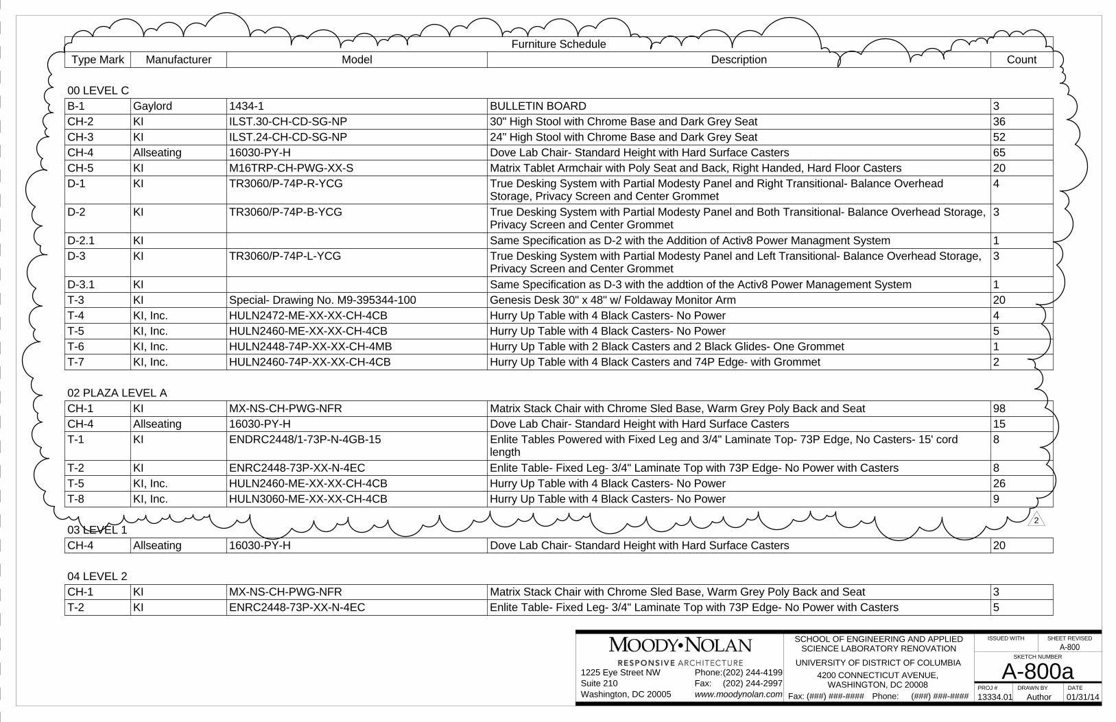
PROJ # DRAWN BY DATE
ISSUED WITH SHEET REVISED
SKETCH NUMBER
Phone: (###) ###-####Fax: (###) ###-####
Suite 210Phone:(202) 244-4199
(202) 244-2997www.moodynolan.com
1225 Eye Street NW
Washington, DC 20005Fax:
A-800a13334.01 01/31/14
SCHOOL OF ENGINEERING AND APPLIEDSCIENCE LABORATORY RENOVATION
UNIVERSITY OF DISTRICT OF COLUMBIA
4200 CONNECTICUT AVENUE,WASHINGTON, DC 20008
Author
Furniture ScheduleType Mark Manufacturer Model Description Count
00 LEVEL CB-1 Gaylord 1434-1 BULLETIN BOARD 3CH-2 KI ILST.30-CH-CD-SG-NP 30" High Stool with Chrome Base and Dark Grey Seat 36CH-3 KI ILST.24-CH-CD-SG-NP 24" High Stool with Chrome Base and Dark Grey Seat 52CH-4 Allseating 16030-PY-H Dove Lab Chair- Standard Height with Hard Surface Casters 65CH-5 KI M16TRP-CH-PWG-XX-S Matrix Tablet Armchair with Poly Seat and Back, Right Handed, Hard Floor Casters 20D-1 KI TR3060/P-74P-R-YCG True Desking System with Partial Modesty Panel and Right Transitional- Balance Overhead
Storage, Privacy Screen and Center Grommet4
D-2 KI TR3060/P-74P-B-YCG True Desking System with Partial Modesty Panel and Both Transitional- Balance Overhead Storage,Privacy Screen and Center Grommet
3
D-2.1 KI Same Specification as D-2 with the Addition of Activ8 Power Managment System 1D-3 KI TR3060/P-74P-L-YCG True Desking System with Partial Modesty Panel and Left Transitional- Balance Overhead Storage,
Privacy Screen and Center Grommet3
D-3.1 KI Same Specification as D-3 with the addtion of the Activ8 Power Management System 1T-3 KI Special- Drawing No. M9-395344-100 Genesis Desk 30" x 48" w/ Foldaway Monitor Arm 20T-4 KI, Inc. HULN2472-ME-XX-XX-CH-4CB Hurry Up Table with 4 Black Casters- No Power 4T-5 KI, Inc. HULN2460-ME-XX-XX-CH-4CB Hurry Up Table with 4 Black Casters- No Power 5T-6 KI, Inc. HULN2448-74P-XX-XX-CH-4MB Hurry Up Table with 2 Black Casters and 2 Black Glides- One Grommet 1T-7 KI, Inc. HULN2460-74P-XX-XX-CH-4CB Hurry Up Table with 4 Black Casters and 74P Edge- with Grommet 2
02 PLAZA LEVEL ACH-1 KI MX-NS-CH-PWG-NFR Matrix Stack Chair with Chrome Sled Base, Warm Grey Poly Back and Seat 98CH-4 Allseating 16030-PY-H Dove Lab Chair- Standard Height with Hard Surface Casters 15T-1 KI ENDRC2448/1-73P-N-4GB-15 Enlite Tables Powered with Fixed Leg and 3/4" Laminate Top- 73P Edge, No Casters- 15' cord
length8
T-2 KI ENRC2448-73P-XX-N-4EC Enlite Table- Fixed Leg- 3/4" Laminate Top with 73P Edge- No Power with Casters 8T-5 KI, Inc. HULN2460-ME-XX-XX-CH-4CB Hurry Up Table with 4 Black Casters- No Power 26T-8 KI, Inc. HULN3060-ME-XX-XX-CH-4CB Hurry Up Table with 4 Black Casters- No Power 9
03 LEVEL 1CH-4 Allseating 16030-PY-H Dove Lab Chair- Standard Height with Hard Surface Casters 20
04 LEVEL 2CH-1 KI MX-NS-CH-PWG-NFR Matrix Stack Chair with Chrome Sled Base, Warm Grey Poly Back and Seat 3T-2 KI ENRC2448-73P-XX-N-4EC Enlite Table- Fixed Leg- 3/4" Laminate Top with 73P Edge- No Power with Casters 5
2
A-800
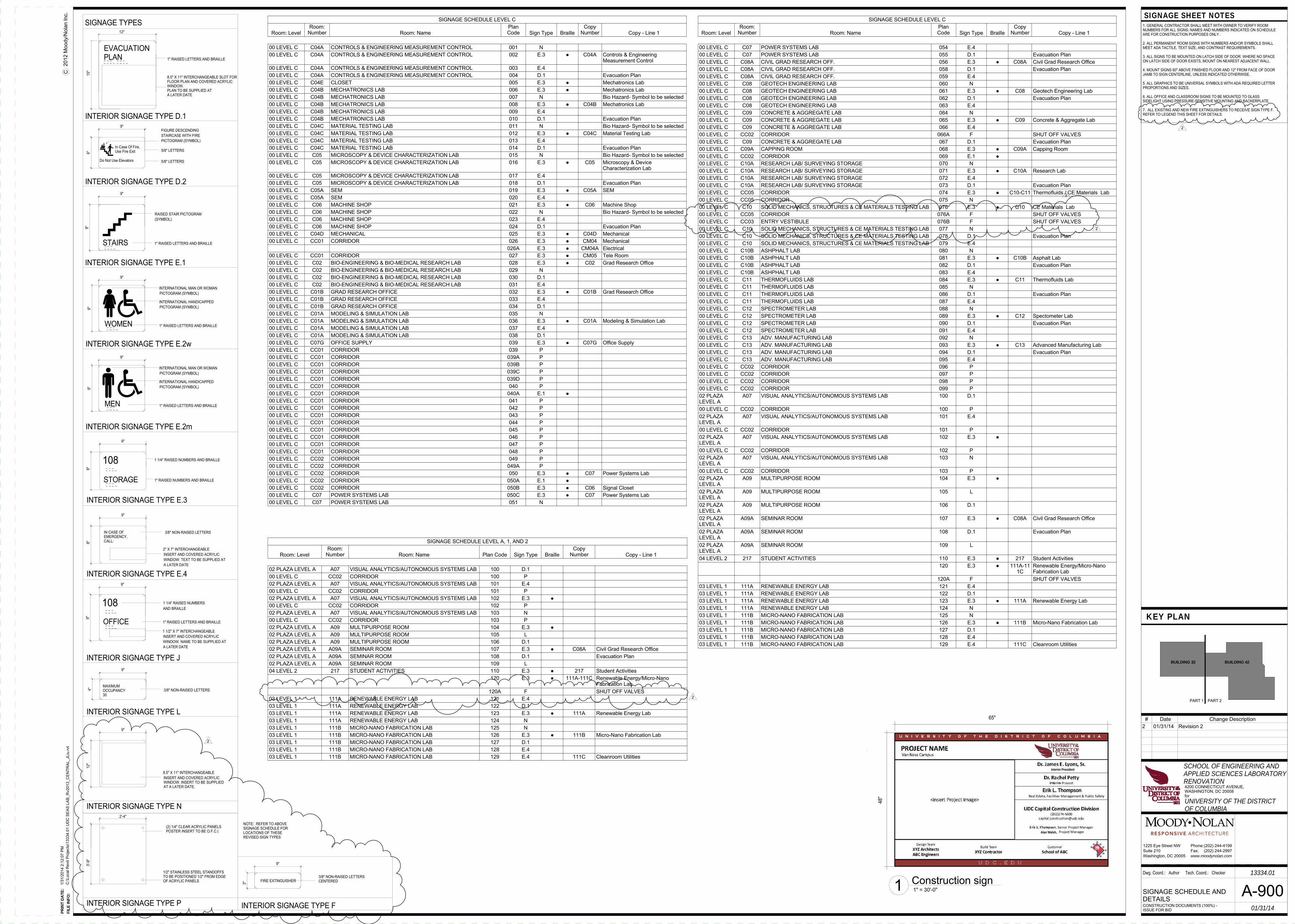
WOMEN
STAIRS
In Case Of Fire,Use Fire Exit
Do Not Use Elevators
INTERIOR SIGNAGE TYPE E.2w
INTERIOR SIGNAGE TYPE E.1
INTERIOR SIGNAGE TYPE D.2
108
108
OFFICE
MAXIMUMOCCUPANCY30
INTERIOR SIGNAGE TYPE L
INTERIOR SIGNAGE TYPE E.3
INTERIOR SIGNAGE TYPE J
1 1/2" X 7" INTERCHANGEABLEINSERT AND COVERED ACRYLICWINDOW. NAME TO BE SUPPLIED ATA LATER DATE
1" RAISED LETTERS AND BRAILLE
AND BRAILLE
1 1/4" RAISED NUMBERS AND BRAILLE
3/8" NON-RAISED LETTERS
FIGURE DESCENDINGSTAIRCASE WITH FIREPICTOGRAM (SYMBOL)
5/8" LETTERS
5/8" LETTERS
1" RAISED LETTERS AND BRAILLE
RAISED STAIR PICTOGRAM(SYMBOL)
INTERNATIONAL HANDICAPPEDPICTOGRAM (SYMBOL)
INTERNATIONAL MAN OR WOMANPICTOGRAM (SYMBOL)
1" RAISED LETTERS AND BRAILLE
1 1/4" RAISED NUMBERS
9"
6"
9"
4"
9"
9"9"
9"
9"
9"
8"
9"
MEN
INTERIOR SIGNAGE TYPE E.2m
INTERNATIONAL HANDICAPPEDPICTOGRAM (SYMBOL)
INTERNATIONAL MAN OR WOMANPICTOGRAM (SYMBOL)
1" RAISED LETTERS AND BRAILLE
9"
9"
INTERIOR SIGNAGE TYPE N
EVACUATIONPLAN
INTERIOR SIGNAGE TYPE D.1
8.5" X 11" INTERCHANGEABLE SLOT FORFLOOR PLAN AND COVERED ACRYLICWINDOW.PLAN TO BE SUPPLIED ATA LATER DATE
12"
15"
1" RAISED LETTERS AND BRAILLE
SIGNAGE TYPES
STORAGE 1" RAISED NUMBERS AND BRAILLE
INTERIOR SIGNAGE TYPE E.4
8"
9"
2" X 7" INTERCHANGEABLEINSERT AND COVERED ACRYLICWINDOW. TEXT TO BE SUPPLIED ATA LATER DATE
IN CASE OFEMERGENCY,CALL:
3/8" NON-RAISED LETTERS
12"
8.5" X 11" INTERCHANGEABLEINSERT AND COVERED ACRYLICWINDOW. INSERT TO BE SUPPLIEDAT A LATER DATE.
9"
INTERIOR SIGNAGE TYPE P
3'-9"
1/2" STAINLESS STEEL STANDOFFSTO BE POSITIONED 1/2" FROM EDGEOF ACRYLIC PANELS
(2) 1/4" CLEAR ACRYLIC PANELSPOSTER INSERT TO BE O.F.C.I.
2'-4"
FIRE EXTINGUISHER
INTERIOR SIGNAGE TYPE F
3/8" NON-RAISED LETTERSCENTERED
9"
3"
SIGNAGE SHEET NOTES1. GENERAL CONTRACTOR SHALL MEET WITH OWNER TO VERIFY ROOMNUMBERS FOR ALL SIGNS; NAMES AND NUMBERS INDICATED ON SCHEDULEARE FOR CONSTRUCTION PURPOSES ONLY .
2. ALL PERMANENT ROOM SIGNS WITH NUMBERS AND/OR SYMBOLS SHALLMEET ADA TACTILE, TEXT SIZE, AND CONTRAST REQUIREMENTS.
3. ALL SIGNS TO BE MOUNTED ON LATCH SIDE OF DOOR. WHERE NO SPACEON LATCH SIDE OF DOOR EXISTS, MOUNT ON NEAREST ADJACENT WALL.
4. MOUNT SIGNS 60" ABOVE FINISHED FLOOR AND 12" FROM FACE OF DOORJAMB TO SIGN CENTERLINE, UNLESS INDICATED OTHERWISE.
5. ALL GRAPHICS TO BE UNIVERSAL SYMBOLS WITH ADA REQUIRED LETTERPROPORTIONS AND SIZES.
6. ALL OFFICE AND CLASSROOM SIGNS TO BE MOUNTED TO GLASSSIDELIGHT USING PRESSURE-SENSITIVE MOUNTING AND BACKERPLATE.
7. ALL EXISTING AND NEW FIRE EXTINGUISHERS TO RECEIVE SIGN TYPE F.REFER TO LEGEND THIS SHEET FOR DETAILS.
48"
65"
Interim President
Erik L. Thompson
Alan Walsh,
2012
Moo
dy/N
olan
Inc.
C
KEY PLAN
Dwg. Coord.: Tech. Coord.:
PR
INT
DA
TE
:
FIL
E IN
FO
:
Suite 210Phone:(202) 244-4199
(202) 244-2997www.moodynolan.com
1225 Eye Street NW
Washington, DC 20005Fax:
PART 2PART 1
BUILDING 32 BUILDING 42
for
SCHOOL OF ENGINEERING ANDAPPLIED SCIENCES LABORATORYRENOVATION4200 CONNECTICUT AVENUE,WASHINGTON, DC 20008
UNIVERSITY OF THE DISTRICTOF COLUMBIA
1/31
/201
4 2:
12:0
7 PM
C:\L
ocal
Rev
it Pr
ojec
ts\1
3334
.01
UD
C S
EAS
L AB_
Rv2
013_
CE
NTR
AL_ J
Liu.
rvt
A-90013334.01
01/31/14
Author Checker
CONSTRUCTION DOCUMENTS (100%) -ISSUE FOR BID
SIGNAGE SCHEDULE ANDDETAILS
SIGNAGE SCHEDULE LEVEL C
Room: LevelRoom:
Number Room: NamePlanCode Sign Type Braille
CopyNumber Copy - Line 1
00 LEVEL C C07 POWER SYSTEMS LAB 054 E.400 LEVEL C C07 POWER SYSTEMS LAB 055 D.1 Evacuation Plan00 LEVEL C C08A CIVIL GRAD RESEARCH OFF. 056 E.3 ● C08A Civil Grad Research Office00 LEVEL C C08A CIVIL GRAD RESEARCH OFF. 058 D.1 Evacuation Plan00 LEVEL C C08A CIVIL GRAD RESEARCH OFF. 059 E.400 LEVEL C C08 GEOTECH ENGINEERING LAB 060 N00 LEVEL C C08 GEOTECH ENGINEERING LAB 061 E.3 ● C08 Geotech Engineering Lab00 LEVEL C C08 GEOTECH ENGINEERING LAB 062 D.1 Evacuation Plan00 LEVEL C C08 GEOTECH ENGINEERING LAB 063 E.400 LEVEL C C09 CONCRETE & AGGREGATE LAB 064 N00 LEVEL C C09 CONCRETE & AGGREGATE LAB 065 E.3 ● C09 Concrete & Aggregate Lab00 LEVEL C C09 CONCRETE & AGGREGATE LAB 066 E.400 LEVEL C CC02 CORRIDOR 066A F SHUT OFF VALVES00 LEVEL C C09 CONCRETE & AGGREGATE LAB 067 D.1 Evacuation Plan00 LEVEL C C09A CAPPING ROOM 068 E.3 ● C09A Capping Room00 LEVEL C CC02 CORRIDOR 069 E.1 ●00 LEVEL C C10A RESEARCH LAB/ SURVEYING STORAGE 070 N00 LEVEL C C10A RESEARCH LAB/ SURVEYING STORAGE 071 E.3 ● C10A Research Lab00 LEVEL C C10A RESEARCH LAB/ SURVEYING STORAGE 072 E.400 LEVEL C C10A RESEARCH LAB/ SURVEYING STORAGE 073 D.1 Evacuation Plan00 LEVEL C CC05 CORRIDOR 074 E.3 ● C10-C11 Thermofluids / CE Materials Lab00 LEVEL C CC05 CORRIDOR 075 N00 LEVEL C C10 SOLID MECHANICS, STRUCTURES & CE MATERIALS TESTING LAB 076 E.3 ● C10 CE Materials Lab00 LEVEL C CC05 CORRIDOR 076A F SHUT OFF VALVES00 LEVEL C CC03 ENTRY VESTIBULE 076B F SHUT OFF VALVES00 LEVEL C C10 SOLID MECHANICS, STRUCTURES & CE MATERIALS TESTING LAB 077 N00 LEVEL C C10 SOLID MECHANICS, STRUCTURES & CE MATERIALS TESTING LAB 078 D.1 Evacuation Plan00 LEVEL C C10 SOLID MECHANICS, STRUCTURES & CE MATERIALS TESTING LAB 079 E.400 LEVEL C C10B ASHPHALT LAB 080 N00 LEVEL C C10B ASHPHALT LAB 081 E.3 ● C10B Asphalt Lab00 LEVEL C C10B ASHPHALT LAB 082 D.1 Evacuation Plan00 LEVEL C C10B ASHPHALT LAB 083 E.400 LEVEL C C11 THERMOFLUIDS LAB 084 E.3 ● C11 Thermofluids Lab00 LEVEL C C11 THERMOFLUIDS LAB 085 N00 LEVEL C C11 THERMOFLUIDS LAB 086 D.1 Evacuation Plan00 LEVEL C C11 THERMOFLUIDS LAB 087 E.400 LEVEL C C12 SPECTROMETER LAB 088 N00 LEVEL C C12 SPECTROMETER LAB 089 E.3 ● C12 Spectometer Lab00 LEVEL C C12 SPECTROMETER LAB 090 D.1 Evacuation Plan00 LEVEL C C12 SPECTROMETER LAB 091 E.400 LEVEL C C13 ADV. MANUFACTURING LAB 092 N00 LEVEL C C13 ADV. MANUFACTURING LAB 093 E.3 ● C13 Advanced Manufacturing Lab00 LEVEL C C13 ADV. MANUFACTURING LAB 094 D.1 Evacuation Plan00 LEVEL C C13 ADV. MANUFACTURING LAB 095 E.400 LEVEL C CC02 CORRIDOR 096 P00 LEVEL C CC02 CORRIDOR 097 P00 LEVEL C CC02 CORRIDOR 098 P00 LEVEL C CC02 CORRIDOR 099 P02 PLAZALEVEL A
A07 VISUAL ANALYTICS/AUTONOMOUS SYSTEMS LAB 100 D.1
00 LEVEL C CC02 CORRIDOR 100 P02 PLAZALEVEL A
A07 VISUAL ANALYTICS/AUTONOMOUS SYSTEMS LAB 101 E.4
00 LEVEL C CC02 CORRIDOR 101 P02 PLAZALEVEL A
A07 VISUAL ANALYTICS/AUTONOMOUS SYSTEMS LAB 102 E.3 ●
00 LEVEL C CC02 CORRIDOR 102 P02 PLAZALEVEL A
A07 VISUAL ANALYTICS/AUTONOMOUS SYSTEMS LAB 103 N
00 LEVEL C CC02 CORRIDOR 103 P02 PLAZALEVEL A
A09 MULTIPURPOSE ROOM 104 E.3 ●
02 PLAZALEVEL A
A09 MULTIPURPOSE ROOM 105 L
02 PLAZALEVEL A
A09 MULTIPURPOSE ROOM 106 D.1
02 PLAZALEVEL A
A09A SEMINAR ROOM 107 E.3 ● C08A Civil Grad Research Office
02 PLAZALEVEL A
A09A SEMINAR ROOM 108 D.1 Evacuation Plan
02 PLAZALEVEL A
A09A SEMINAR ROOM 109 L
04 LEVEL 2 217 STUDENT ACTIVITIES 110 E.3 ● 217 Student Activities120 E.3 ● 111A-11
1CRenewable Energy/Micro-NanoFabrication Lab
120A F SHUT OFF VALVES03 LEVEL 1 111A RENEWABLE ENERGY LAB 121 E.403 LEVEL 1 111A RENEWABLE ENERGY LAB 122 D.103 LEVEL 1 111A RENEWABLE ENERGY LAB 123 E.3 ● 111A Renewable Energy Lab03 LEVEL 1 111A RENEWABLE ENERGY LAB 124 N03 LEVEL 1 111B MICRO-NANO FABRICATION LAB 125 N03 LEVEL 1 111B MICRO-NANO FABRICATION LAB 126 E.3 ● 111B Micro-Nano Fabrication Lab03 LEVEL 1 111B MICRO-NANO FABRICATION LAB 127 D.103 LEVEL 1 111B MICRO-NANO FABRICATION LAB 128 E.403 LEVEL 1 111B MICRO-NANO FABRICATION LAB 129 E.4 111C Cleanroom Utilities
SIGNAGE SCHEDULE LEVEL C
Room: LevelRoom:
Number Room: NamePlanCode Sign Type Braille
CopyNumber Copy - Line 1
00 LEVEL C C04A CONTROLS & ENGINEERING MEASUREMENT CONTROL 001 N00 LEVEL C C04A CONTROLS & ENGINEERING MEASUREMENT CONTROL 002 E.3 ● C04A Controls & Engineering
Measurement Control00 LEVEL C C04A CONTROLS & ENGINEERING MEASUREMENT CONTROL 003 E.400 LEVEL C C04A CONTROLS & ENGINEERING MEASUREMENT CONTROL 004 D.1 Evacuation Plan00 LEVEL C C04E CLOSET 005 E.3 ● Mechatronics Lab00 LEVEL C C04B MECHATRONICS LAB 006 E.3 ● Mechatronics Lab00 LEVEL C C04B MECHATRONICS LAB 007 N Bio Hazard- Symbol to be selected00 LEVEL C C04B MECHATRONICS LAB 008 E.3 ● C04B Mechatronics Lab00 LEVEL C C04B MECHATRONICS LAB 009 E.400 LEVEL C C04B MECHATRONICS LAB 010 D.1 Evacuation Plan00 LEVEL C C04C MATERIAL TESTING LAB 011 N Bio Hazard- Symbol to be selected00 LEVEL C C04C MATERIAL TESTING LAB 012 E.3 ● C04C Material Testing Lab00 LEVEL C C04C MATERIAL TESTING LAB 013 E.400 LEVEL C C04C MATERIAL TESTING LAB 014 D.1 Evacuation Plan00 LEVEL C C05 MICROSCOPY & DEVICE CHARACTERIZATION LAB 015 N Bio Hazard- Symbol to be selected00 LEVEL C C05 MICROSCOPY & DEVICE CHARACTERIZATION LAB 016 E.3 ● C05 Microscopy & Device
Characterization Lab00 LEVEL C C05 MICROSCOPY & DEVICE CHARACTERIZATION LAB 017 E.400 LEVEL C C05 MICROSCOPY & DEVICE CHARACTERIZATION LAB 018 D.1 Evacuation Plan00 LEVEL C C05A SEM 019 E.3 ● C05A SEM00 LEVEL C C05A SEM 020 E.400 LEVEL C C06 MACHINE SHOP 021 E.3 ● C06 Machine Shop00 LEVEL C C06 MACHINE SHOP 022 N Bio Hazard- Symbol to be selected00 LEVEL C C06 MACHINE SHOP 023 E.400 LEVEL C C06 MACHINE SHOP 024 D.1 Evacuation Plan00 LEVEL C C04D MECHANICAL 025 E.3 ● C04D Mechanical00 LEVEL C CC01 CORRIDOR 026 E.3 ● CM04 Mechanical
026A E.3 ● CM04A Electrical00 LEVEL C CC01 CORRIDOR 027 E.3 ● CM05 Tele Room00 LEVEL C C02 BIO-ENGINEERING & BIO-MEDICAL RESEARCH LAB 028 E.3 ● C02 Grad Research Office00 LEVEL C C02 BIO-ENGINEERING & BIO-MEDICAL RESEARCH LAB 029 N00 LEVEL C C02 BIO-ENGINEERING & BIO-MEDICAL RESEARCH LAB 030 D.100 LEVEL C C02 BIO-ENGINEERING & BIO-MEDICAL RESEARCH LAB 031 E.400 LEVEL C C01B GRAD RESEARCH OFFICE 032 E.3 ● C01B Grad Research Office00 LEVEL C C01B GRAD RESEARCH OFFICE 033 E.400 LEVEL C C01B GRAD RESEARCH OFFICE 034 D.100 LEVEL C C01A MODELING & SIMULATION LAB 035 N00 LEVEL C C01A MODELING & SIMULATION LAB 036 E.3 ● C01A Modeling & Simulation Lab00 LEVEL C C01A MODELING & SIMULATION LAB 037 E.400 LEVEL C C01A MODELING & SIMULATION LAB 038 D.100 LEVEL C C07G OFFICE SUPPLY 039 E.3 ● C07G Office Supply00 LEVEL C CC01 CORRIDOR 039 P00 LEVEL C CC01 CORRIDOR 039A P00 LEVEL C CC01 CORRIDOR 039B P00 LEVEL C CC01 CORRIDOR 039C P00 LEVEL C CC01 CORRIDOR 039D P00 LEVEL C CC01 CORRIDOR 040 P00 LEVEL C CC01 CORRIDOR 040A E.1 ●00 LEVEL C CC01 CORRIDOR 041 P00 LEVEL C CC01 CORRIDOR 042 P00 LEVEL C CC01 CORRIDOR 043 P00 LEVEL C CC01 CORRIDOR 044 P00 LEVEL C CC01 CORRIDOR 045 P00 LEVEL C CC01 CORRIDOR 046 P00 LEVEL C CC01 CORRIDOR 047 P00 LEVEL C CC01 CORRIDOR 048 P00 LEVEL C CC02 CORRIDOR 049 P00 LEVEL C CC02 CORRIDOR 049A P00 LEVEL C CC02 CORRIDOR 050 E.3 ● C07 Power Systems Lab00 LEVEL C CC02 CORRIDOR 050A E.1 ●00 LEVEL C CC02 CORRIDOR 050B E.3 ● C06 Signal Closet00 LEVEL C C07 POWER SYSTEMS LAB 050C E.3 ● C07 Power Systems Lab00 LEVEL C C07 POWER SYSTEMS LAB 051 N
1" = 30'-0"1 Construction sign
SIGNAGE SCHEDULE LEVEL A, 1, AND 2
Room: LevelRoom:
Number Room: Name Plan Code Sign Type BrailleCopy
Number Copy - Line 1
02 PLAZA LEVEL A A07 VISUAL ANALYTICS/AUTONOMOUS SYSTEMS LAB 100 D.100 LEVEL C CC02 CORRIDOR 100 P02 PLAZA LEVEL A A07 VISUAL ANALYTICS/AUTONOMOUS SYSTEMS LAB 101 E.400 LEVEL C CC02 CORRIDOR 101 P02 PLAZA LEVEL A A07 VISUAL ANALYTICS/AUTONOMOUS SYSTEMS LAB 102 E.3 ●00 LEVEL C CC02 CORRIDOR 102 P02 PLAZA LEVEL A A07 VISUAL ANALYTICS/AUTONOMOUS SYSTEMS LAB 103 N00 LEVEL C CC02 CORRIDOR 103 P02 PLAZA LEVEL A A09 MULTIPURPOSE ROOM 104 E.3 ●02 PLAZA LEVEL A A09 MULTIPURPOSE ROOM 105 L02 PLAZA LEVEL A A09 MULTIPURPOSE ROOM 106 D.102 PLAZA LEVEL A A09A SEMINAR ROOM 107 E.3 ● C08A Civil Grad Research Office02 PLAZA LEVEL A A09A SEMINAR ROOM 108 D.1 Evacuation Plan02 PLAZA LEVEL A A09A SEMINAR ROOM 109 L04 LEVEL 2 217 STUDENT ACTIVITIES 110 E.3 ● 217 Student Activities
120 E.3 ● 111A-111C Renewable Energy/Micro-NanoFabrication Lab
120A F SHUT OFF VALVES03 LEVEL 1 111A RENEWABLE ENERGY LAB 121 E.403 LEVEL 1 111A RENEWABLE ENERGY LAB 122 D.103 LEVEL 1 111A RENEWABLE ENERGY LAB 123 E.3 ● 111A Renewable Energy Lab03 LEVEL 1 111A RENEWABLE ENERGY LAB 124 N03 LEVEL 1 111B MICRO-NANO FABRICATION LAB 125 N03 LEVEL 1 111B MICRO-NANO FABRICATION LAB 126 E.3 ● 111B Micro-Nano Fabrication Lab03 LEVEL 1 111B MICRO-NANO FABRICATION LAB 127 D.103 LEVEL 1 111B MICRO-NANO FABRICATION LAB 128 E.403 LEVEL 1 111B MICRO-NANO FABRICATION LAB 129 E.4 111C Cleanroom Utilities
# Date Change Description2 01/31/14 Revision 2
2
2
NOTE: REFER TO ABOVESIGNAGE SCHEDULE FORLOCATIONS OF THESEREVISED SIGN TYPES
2
2
2
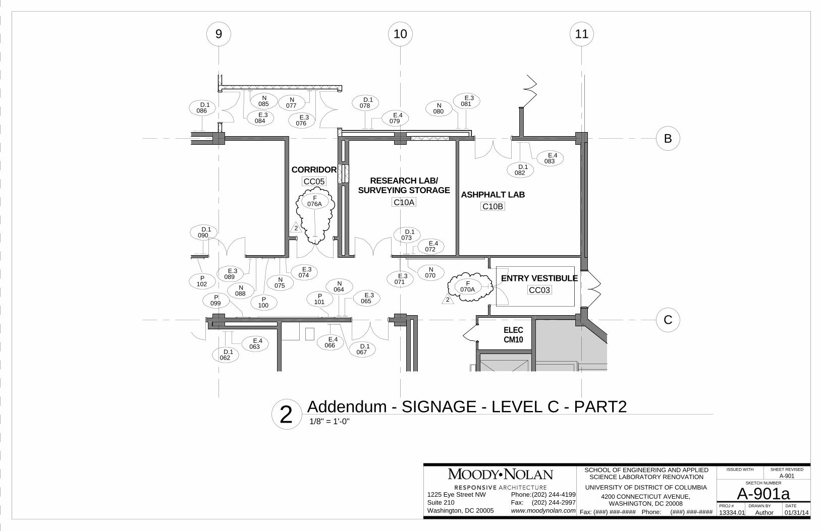
9 10 11
B
C
ASHPHALT LABC10B
RESEARCH LAB/SURVEYING STORAGE
C10A
CORRIDORCC05
ENTRY VESTIBULECC03
ELECCM10
089E.3
088N
090D.1
084E.3
085N
077N
076E.3
074E.3
075N
086D.1 078
D.1
079E.4
080N 081
E.3
082D.1
083E.4
072E.4
073D.1
071E.3 070
N
065E.3
064N
067D.1066
E.4063
E.4
062D.1
101P
099P
102P
100P
076AF
070AF
2
2
PROJ # DRAWN BY DATE
ISSUED WITH SHEET REVISED
SKETCH NUMBER
Phone: (###) ###-####Fax: (###) ###-####
Suite 210Phone:(202) 244-4199
(202) 244-2997www.moodynolan.com
1225 Eye Street NW
Washington, DC 20005Fax:
A-901a13334.01 01/31/14
SCHOOL OF ENGINEERING AND APPLIEDSCIENCE LABORATORY RENOVATION
UNIVERSITY OF DISTRICT OF COLUMBIA
4200 CONNECTICUT AVENUE,WASHINGTON, DC 20008
Author
1/8" = 1'-0"2 Addendum - SIGNAGE - LEVEL C - PART2
A-901
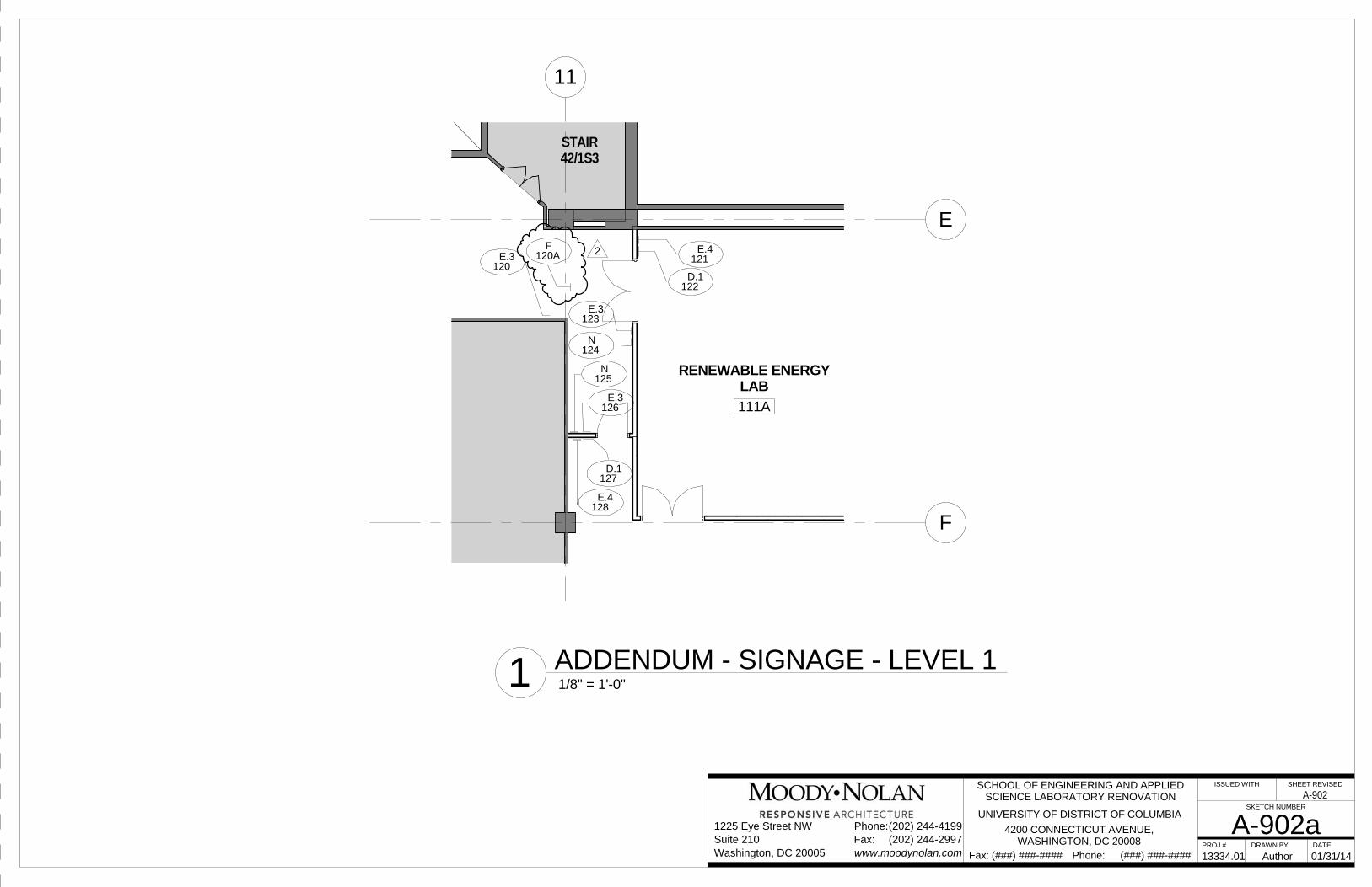
11
E
F
RENEWABLE ENERGYLAB
111A
STAIR42/1S3
121E.4
122D.1
126E.3
128E.4
125N
127D.1
120E.3
123E.3
124N
120AF 2
PROJ # DRAWN BY DATE
ISSUED WITH SHEET REVISED
SKETCH NUMBER
Phone: (###) ###-####Fax: (###) ###-####
Suite 210Phone:(202) 244-4199
(202) 244-2997www.moodynolan.com
1225 Eye Street NW
Washington, DC 20005Fax:
A-902a13334.01 01/31/14
SCHOOL OF ENGINEERING AND APPLIEDSCIENCE LABORATORY RENOVATION
UNIVERSITY OF DISTRICT OF COLUMBIA
4200 CONNECTICUT AVENUE,WASHINGTON, DC 20008
Author
1/8" = 1'-0"1 ADDENDUM - SIGNAGE - LEVEL 1
A-902