EQ Series Electric Chain Hoist (125kg to 1t) EQ Series ...
124
OM-EQ1ZZZ-CEE-03 To Customer • Thank you for purchasing KITO Electric Hoist (EQ). • Operators and maintenance engineers are requested to read this manual. After reading, please keep this manual at hand for future use. • This product is designed considering the environment protection. The product contains none of six hazardous substances specified by European RoHS Directives nor asbestos. Suspended Type (hoist only) : EQ Motorized Trolley Type : EQM Manual Trolley Type : EQSP EQ Series Electric Chain Hoist (125kg to 1t) Owner's Manual Original Instruction
Transcript of EQ Series Electric Chain Hoist (125kg to 1t) EQ Series ...

Global Website: kito.com
EQ Series Electric Chain H
oist (125kg to 1t) Ow
ner's Manual
OM-EQ1ZZZ-CEE-03
To Customer
• Thank you for purchasing KITO Electric Hoist (EQ).• Operators and maintenance engineers are requested to read this manual.
After reading, please keep this manual at hand for future use. • This product is designed considering the environment protection. The product contains none of six hazardous
substances specified by European RoHS Directives nor asbestos.
Suspended Type (hoist only) : EQMotorized Trolley Type : EQMManual Trolley Type : EQSP
EQ Series Electric Chain Hoist (125kg to 1t)
Owner's Manual
Original Instruction
Utilizing 70% post-consumer recycled paper pulp
KITO Europe GmbH Heerdter Lohweg 93, D-40549 Düsseldorf, Germany TEL: +49-(0)211-528009-00 FAX: +49-(0)211-528009-59 E-mail: [email protected] URL: http://www.kito.net/
KITO corporation Tokyo Head Office: SHINJUKU NS Building 9F, 2-4-1, Nishi-Shinjuku, Shinjuku-ku, Tokyo 163-0809, Japan URL: http://kito.com/ Head Office & Factory: 2000 Tsuijiarai Showa-Cho, Nakakoma-Gun, Yamanashi 409-3853, Japan URL: http://kito.com/

1232
IntroductionThis electric hoist EQ is designed and manufactured for the purpose to lift and lower a load within a normal work environment. The motorized trolley MR2Q and the manual trolley are designed and manufactured for the purpose to move the lifted load laterally with the combination with the electric hoist. Movement of a load in a 3D direction such as up/down, forward/backward and right/left is also enabled by combining with a crane.
This Owner's Manual is intended for those operating the KITO electric hoist EQ and maintenance engineers (* pesonnel with expertise). Other than this manual, Disassembly/Reassembly Manual is also available for the maintenance engineers. Assign the maintenance engineers and use these materials for inspection and repair. Please contact the nearest distributor or KITO for these materials.
* A person who has a thorough knowledge of the structure and rolls concerning Electric chain block and is recognized as an expert by an entity.
Introduction ............................................................................................2
Safety Precautions ................................................................................4
Chapter 1 Handling the Product ..........................................................7
Chapter 2 Inspection ..........................................................................55
Chapter 3 Troubleshooting ................................................................87
Appendix ............................................................................................107
Warranty .............................................................................................120
EC Declaration of Conformity ..........................................................123
Table of Contents
■Disclaimer ● KITO shall not be liable for any damage incurred thereof due to natural disaster such as fire, earth quake and thunderbolt, conduct by third party, accident, willful conduct or negligence by customer, erroneous use and other use exceeding the operational condition.
● KITO shall not be liable for any incidental damage due to the use or non-use of the product such as the loss of business profit, suspension of business and damage of the lifted load.
● KITO shall not be liable for any damage arising from negligence of the contents in the Owner's Manual and the use of the product exceeding the scope of its specification.
● KITO shall not be liable for any damage arising from the malfunction due to the combination of the product with other devices in which KITO is not concerned.
● KITO shall be indemnified from any loss of life, bodily injury and property damage due to the use of our product for which it has passed 10 years since its delivery.
● KITO shall not be liable to supply the spare parts for the product for which it has passed for 15 years since the discontinue of the product.
DECLARATION OF CONFORMITY
We, KITO Corporation,2000 Tsuijiarai, Showa-cho,Nakakoma-gun, Yamanashi-ken, 409-3853, Japan
declare under our sole responsibility that the products:Electric chain hoist EQ, model EQfor use with or without the relevant trolley in capacity of 125kg to 1t to which this declaration relates is in conformity with the following EC directives and standards.
EC directives:Machinery Directive 2006/42/ECEMC Directive 2014/30/EULow Voltage Directive 2014/35/EU
Harmonized standards:EN ISO 12100:2010 Risk assessment and risk reductionEN 14492-2:2006+A1:2009 Power driven hoistsEN 818-7:2002+A1:2008 Short link chain for lifting purposesEN ISO 13850:2008 Emergency stopEN 60204-1:2006 Electrical equipment of machinesEN 61000-6-4:2007 Electromagnetic compatibility (Emission)EN 61000-6-2:2005 Electromagnetic compatibility (Immunity)
National standards:FEM 9.511:1986 Classification of mechanisms FEM 9.683:1995 Section of lifting and travel motors
EC DECLARATION OF CONFORMITY

3
■Restriction on Use ● The product described herein is not designed or manufactured for transporting people. Do not use the product for that purpose.
● The product described herein is designed for the materials handling work such as lifting/lowering and traveling the load under ordinary operational condition. Do not use the product for the work other than materials handling work.
● Do not assemble the product into machinery not for materials handling, as a part of it.
■Operators ● Read carefully this Owner’s Manual and the instruction manuals of related products, fully understand their contents, and the use and operate the product.
● Be sure to ware the proper clothing and protective equipment when using and operating the product.
■Laws and StandardsCarry out installation, inspections, operations, maintenance management in accordance with the laws and standards of the country and region where the product is used.
An application before installation or a test before beginning usage may be required. Furthermore, the tester may be required to have specific qualifications. Be sure to check the laws and standards of the corresponding country and region before using the product.

4
■General Matters on Handling and Control
• This product shall not be disassembled and repaird by personnel other than maintenance engineers.Other than this manual, Disassembly/Assembly Manual and Parts List are provided for the maintenance engineers. Perform the disassembling and repair by the maintenance engineer in accordance with these materials for maintenance.
• Do not modify the product and its accessories.
Failure to comply with these instructions may result in death or serious injury.
Prohibited
Mandatory
• Understand the contents of the Owner’s Manual sufficiently. Then operate the Electric chain hoist. • Warning label is affixed to each part of the product. Follow the instruction described in the warning label.
Failure to comply with these instructions may result in death or serious injury.
Safety PrecautionsImproper use of electric chain hoist causes danger such as drop of lifted load. Read this Owner’s Manual carefully before installation, operation and maintenance. Use the product after understanding the product knowledge, safety information and precautions. This Owner’s Manual classifies the safety information and precautions into two categories of “DANGER” “WARNING” and “CAUTION”.Also read the instruction manual of the device associated with electric chain hoist, and follow the described contents.
Description of Safety Symbols
Means “Prohibited” or “You must not do”.Prohibited action is shown in the circle or described near the circle.This Owner’s Manual uses as the general prohibition.
Means “Mandatory Action” or “You must do”.Required action is shown in the circle or described near the circle.This Owner’s Manual uses as the general instruction.
Further, the event described in CAUTION may result in serious accident depending on the situation. Both DANGER and CAUTION describe important contents. Please follow the instruction.After reading, please keep this manual at hand for future use by the user.
Indicates an imminently hazardous situation which, if not avoided, will result in death or serious injury.
Description of Signal Words
WARNING
DANGER
CAUTION
Indicates a potentially hazardous situation which, if not avoided, could result in death or serious injury.
Indicates a potentially hazardous situation which, if not avoided, may result in minor or moderate injury. It may also be used to alert against unsafe practices.
Prohibited
Mandatory
DANGER

5
CAUTION • Do not drag or drop the product when carrying.
Otherwise it causes damage or flaw of the electric chain hoist, bodily injury or loss of property due to the drop of the lifted load.Prohibited
Mandatory
• When discarding the product, disassemble it not to be used and discard in accordance with the ordinances of local government or the rules specified by the business entity.Ask the local government or the relevant section for the details.Refer to “Disassembly/Assembly Manual” for disassembling, or contact KITO.(This product uses oil. We prepare MSDS (Materials Safety Data Sheet) for the oil. Contact KITO for it.)
• Carry out daily inspection by user. • Carry out inspection (monthly, annual) by maintenance engineer. • Keep the record of the inspection.
Failure to comply with these instructions causes bodily injury or loss of property.
■General Matters on Handling of EQ Series Electric Chain HoistThe EQ series electric chain hoist is controlled by VFD for important items related to safety such as operation, braking and emergency stop. Be sure to follow the safety precautions below as well as the above safety precautions.
• Do not reassemble the EQ series electric chain hoist to contactor type. • Do not change parameters.
When parameters need to be changed, ask distributor or KITO. • Do not carry out the work such as maintenance and inspection within 5 minutes after power off.
Wait for the completion of discharging of the capacitor inside the VFD. • Do not change the connection of the VFD.
When the wires were removed for any reason, connect them again correctly checking the wiring diagram inside the controller cover.
• Do not carry out withstand voltage test and insulation resistance measurement of a circuit by megger while the VFD is connected.
• Do not turn off the power while operating. • Never turn off the power when a load is suspended.
Never, under any circumstances, turn off the power when a load is suspended. Doing so will cause the load to be slightly lowered after the power is turned on again due to control system initial preparation.
Failure to comply with these instructions may result in death or serious injury and the damage of VFD.
Prohibited
DANGER
Mandatory
• USE KITO genuine VFD.The VFD requires the special specification for KITO. Be sure to use genuine VFD.
Failure to comply with this instruction may result in death or serious injury.

6
7
Chapter 1Handling the Product
This chapter describes mainly how to use, assemble and install, and the check after installation. It also describes the daily inspection items before use.
Type and Names of Each Part ..........................................................8Opening the Package ......................................................................11Product Specification and Operational Environment ..................16How to Use ......................................................................................18
● Daily Inspection of Electric Chain Hoist (EQ) ...............................19 ● Daily Inspection of Motorized Trolley (EQM) .............................24 ● Daily Inspection of Manual Trolley (EQSP) ...............................25 ● How to Operate the Push Button Switches ...............................26 ● Operation ......................................................................................29 ● Speed Change of Dual Speed for EQ Model .............................32 ● How to Sling the Load Properly .................................................32 ● How to Suppress the Swinging of a Load .................................32 ● Precautions After Work ...............................................................33
Work Flow of Assembling and Installation....................................34Assembling ......................................................................................35Assembling Parts to Electric Chain Hoist .....................................35
● Combination with the Trolley ......................................................38 ● Checking Power and Power Cable .............................................45 ● Connecting Cables ......................................................................47
Installation ........................................................................................50 ● Connecting Power and Power cable ..........................................50 ● Installing the Suspended Type (hoist only) ..................................50 ● Installing the Trolley Combined Model .......................................51
Check after Installation ...................................................................54
8
Type and Names of Each Part
Mandatory
• Warning labels are affixed to each part other than above. Be sure to follow the instructions in the label.Failure to comply with the contents of the label may result in death or serious injury.
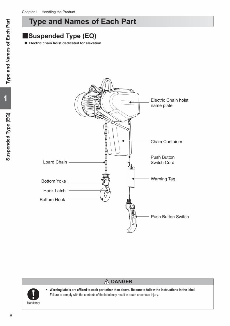
■Suspended Type (EQ) ● Electric chain hoist dedicated for elevation
Chapter 1 Handling the Product
1
Type
and
Nam
es o
f Eac
h Pa
rtSu
spen
ded
Type
(EQ
)
DANGER
Electric Chain hoistname plate
Chain Container
Push ButtonSwitch Cord
Warning Tag
Push Button Switch
Loard Chain
Bottom Yoke
Hook Latch
Bottom Hook

9
■Motorized Trolley Type (EQM) ● Electric Chain Hoist combined with motorized trolley (MR2Q) for elevation and traveling motion
Type and Nam
es of Each PartM
otorized Trolley Type (EQM
)
1
(to be continued)
Mandatory
• Warning labels are affixed to each part other than above. Be sure to follow the instructions in the label.Failure to comply with the contents of the label can result in serious bodily injury or death.
DANGER
Relay Cable
Connection Box
Motorized trolleynameplate
Cable Support Bar
Electric chain hoistnameplate
Chain Container
Push ButtonSwitch Cord
Power Cable
Warning Tag
Push Button Switch
Load Chain
Bottom Yoke
Hook latch
Bottom Hook

10
■Manual Trolley Type (EQSP) ● The electric chain hoist equipped with the plain trolley (TSP) enabling lateral motion by moving the load manually. For light
work.
Type and Names of Each Part (continued)Chapter 1 Handling the Product
1
Type
and
Nam
es o
f Eac
h Pa
rtM
anua
l Tro
lley
Type
(EQ
SP)
Mandatory
• Warning labels are affixed to each part other than above. Be sure to follow the instructions in the label.Failure to comply with the contents of the label can result in serious bodily injury or death.
DANGER
Name plate
Plain Trolley(TSP)
Bumper
Chain Container
Push Button Switch Cord
Warning Tag
Load Chain
Bottom Yoke
Hook Latch
Bottom Hook
Push Button Switch
11
Opening the Package
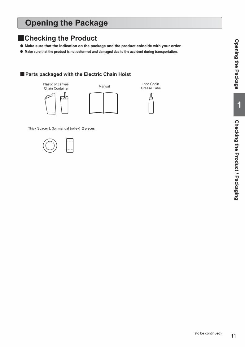
■Checking the Product ● Make sure that the indication on the package and the product coincide with your order. ● Make sure that the product is not deformed and damaged due to the accident during transportation.
■Parts packaged with the Electric Chain Hoist
Plastic or canvas Chain Container
Thick Spacer L (for manual trolley) 2 pieces
ManualLoad Chain Grease Tube
Opening the Package
Checking the Product / Packaging
1
(to be continued)
12
Opening the Package (continued)
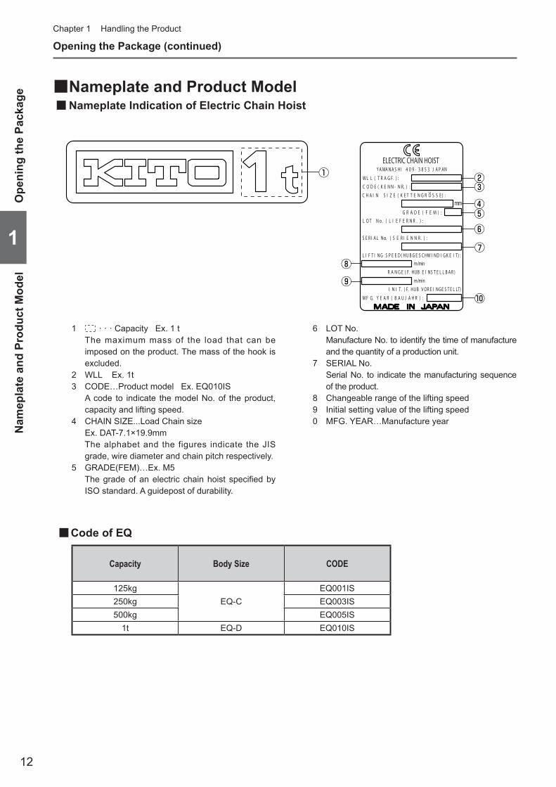
■Nameplate and Product Model ■Nameplate Indication of Electric Chain Hoist
Chapter 1 Handling the Product
1 · · · Capacity Ex. 1 t The maximum mass of the load that can be
imposed on the product. The mass of the hook is excluded.
2 WLL Ex. 1t3 CODE…Product model Ex. EQ010IS A code to indicate the model No. of the product,
capacity and lifting speed. 4 CHAIN SIZE...Load Chain size Ex. DAT-7.1×19.9mm The alphabet and the figures indicate the JIS
grade, wire diameter and chain pitch respectively. 5 GRADE(FEM)…Ex. M5 The grade of an electric chain hoist specified by
ISO standard. A guidepost of durability.
6 LOT No. Manufacture No. to identify the time of manufacture
and the quantity of a production unit.7 SERIAL No. Serial No. to indicate the manufacturing sequence
of the product.8 Changeable range of the lifting speed9 Initial setting value of the lifting speed0 MFG. YEAR…Manufacture year
■Code of EQ
1
Ope
ning
the
Pack
age
Nam
epla
te a
nd P
rodu
ct M
odel
⑤
① ②
④
⑥
⑧⑨
③
⑦
⑩
Capacity Body Size CODE
125kgEQ-C
EQ001IS250kg EQ003IS500kg EQ005IS
1t EQ-D EQ010IS

13
■Nameplate Indication of Motorized Trolley
1 · · · Capacity Ex. 1 t The maximum mass of the load that can be
imposed on the product. The mass of the hook is excluded.
2 WLL · · · Ex. 1t3 CODE · · · Product model Ex. MR2Q010IS Indicates the model No. of the product, capacity
and lifting speed of the product.4 LOT No. Manufacture No. to identify the time of manufacture
and the quantity of a production unit.5 SERIAL No. Serial No. to indicate the manufacturing sequence of
the product.
■Code of MR2Q
Opening the Package
Nam
eplate and Product Model
1
(to be continued)
②
④
⑤
⑥
③
⑦
⑧
①
CapacityCODE
Model MR2Q dual speed VFD modelStandard speed
125kg250kg500kg
1t
MR2Q010IS
6 Changeable range the traveling speed.7 Initial setting value of the traveling speed.8 MFG. YEAR…Manufacture year

14
Opening the Package (continued)Chapter 1 Handling the Product
■Nameplate Indication of Manual Trolley
1 · · · Capacity Ex. 1 t The maximum mass of the load that can be imposed on the product.
The mass of the hook is excluded.2 LOT No. Manufacture No. to identify the time of manufacture and the production
lot.3 SERIAL No. Serial number to indicate the manufacturing sequence of the product.4 MFG. YEAR · · · Manufacture year
YAMANASHI409-3853 JAPANMADE IN JAPAN
KENN-NR./CODE:TSP010
LIEFERNR./LOT No.TS2-
SERIENNR./SERIAL No.
BJ./MFG.YEAR
WLLTRAGF. ①
④
②
③
1
Ope
ning
the
Pack
age
Nam
epla
te a
nd P
rodu
ct M
odel
15
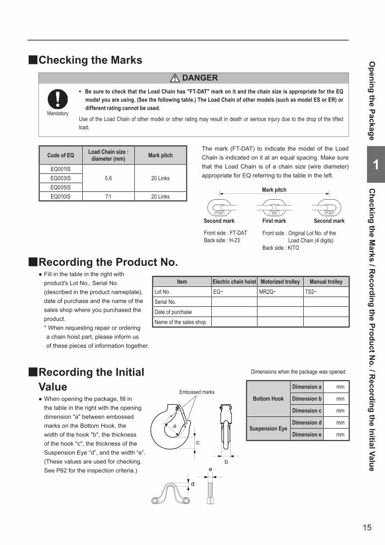
■Checking the Marks
Code of EQ Load Chain size : diameter (mm) Mark pitch
EQ001IS5.6 20 LinksEQ003IS
EQ005ISEQ010IS 7.1 20 Links
FT-DAT 0000 FT-DAT
Mark pitch
First markSecond mark Second mark
Front side : FT-DATBack side : H-23
Front side : Original Lot No. of the Load Chain (4 digits)Back side : KITO
• Be sure to check that the Load Chain has "FT-DAT" mark on it and the chain size is appropriate for the EQ model you are using. (See the following table.) The Load Chain of other models (such as model ES or ER) or different rating cannot be used.
Use of the Load Chain of other model or other rating may result in death or serious injury due to the drop of the lifted load.
Mandatory
The mark (FT-DAT) to indicate the model of the Load Chain is indicated on it at an equal spacing. Make sure that the Load Chain is of a chain size (wire diameter) appropriate for EQ referring to the table in the left.
Opening the Package
Checking the M
arks / Recording the Product N
o. / Recording the Initial Value
1
DANGER
■Recording the Initial Value
● When opening the package, fill in the table in the right with the opening dimension "a" between embossed marks on the Bottom Hook, the width of the hook "b", the thickness of the hook "c", the thickness of the Suspension Eye “d”, and the width “e”. (These values are used for checking. See P62 for the inspection criteria.)
Dimensions when the package was opened
Bottom Hook
Dimension a mm
Dimension b mm
Dimension c mm
Suspension Eye Dimension d mm
Dimension e mm
■Recording the Product No. ● Fill in the table in the right with product's Lot No., Serial No. (described in the product nameplate), date of purchase and the name of the sales shop where you purchased the product.* When requesting repair or ordering a chain hoist part, please inform us of these pieces of information together.
Item Electric chain hoist Motorized trolley Manual trolleyLot No. EQ− MR2Q− TS2−Serial No.Date of purchaseName of the sales shop
b
c
a
Embossed marks
e
d

16
1
Produ
ct Sp
ecific
ation
and O
perat
ional
Envir
onme
ntSt
anda
rd S
peci
ficat
ion
Product category Motor Insulation Class
Voltage range Operating Voltage50Hz 60Hz
230V Class
B
220V 220V
DC24V230V 230V
400V Class380V 380V400V 440V415V —
Product Specification and Operational Environment
■Standard SpecificationIntermittent ratings : EQ series(100 % of the capacity): Dual speed VFD model (high speed/low speed) — 40/20 % ED (120/240 rev/h) : MR2Q series(100 % of the capacity): Dual speed VFD model (high speed/low speed) — 27/13 % ED (78/162 rev/h)Grade * 1 : ISO-M5 or M4, FEM-2 or ASME-H4Protection : Hoist IP55, Push button IP65Operation ........................... Push button switch operation / 3-Push Button Switch set for hoist only and Manual trolley type / 5- or 7-Push
Button Switch set for motorized trolley combined modelPower supply method ........Power supply through cabtyre cableColor ..................................Body: KITO Metalic gray, Controller Cover and Fan Cover: KITO Yellow (Equivalent to Munsell 7.2 YR 6.5/14.5)Noise level : EQ, dual speed VFD model 80dB or less (A scale: measured at 1 m away from the Electric chain hoist) : MR2Q 85dB or less (A scale: measured at 1 m away from the Electric chain hoist)Braking capacity : 150% of the capacity or moreOther ..................................Power Cable length 5 m/10 m (Standard)Sound power level : MR2Q 96db or less (A scale)
The operational environment of the electric chain hoist and motorized trolley is as follows:
Chapter 1 Handling the Product
NOTE • Operate the electric chain hoist with the rated voltage. • Do not use the electric chain hoist exceeding the intermittent ratings.
* Grade 1
CapacityCode GRADE
Dual speedISO ASME FEM
Dual speed Dual speed Dual speed125kg EQ001IS
M6 H4 3m250kg EQ003IS
500kg EQ005IS
1t EQ010IS M5 H4 2m
Loading status
Total operating hour h800 1600 3200 6300 12500 25000
Light — — — — M5 M6Medium — — — M5 M6 —Heavy — — M5 M6 — —
Ultra heavy — M5 M6 — — —* Rate of loading
Light : A case where the capacity is rarely applied. Usually the hoist is used with a light load.
Medium : A case where the capacity is applied considerably frequently. Usually the hoist is used with a medium load.
Heavy : A case where the capacity is applied considerably frequently. Usually the hoist is used with a heavy load.
Ultra heavy : A case where the capacity is applied constantly.

17
Hoist duty class Typical areas of application
Operation time ratings at K=0.65Unlformly distributed
work periodsInfrequent
work periodsMax. on
time, min / hrMax. No. starts / hr
Max. on time from cold start, min
Max. No. of starts
H2
Light machine shop fabricating, service,and maintenance; loads and utilization randomly distributed; capacitys infrequently handled.
7.6 (12.5%) 75 15 100
H3General machine shop fabricating, assembly, storage, and warehousing; loads and utilization randomly distributed.
15 (25%) 150 30 200
H4
High volume handing in steel warehouses, machine shops, fabricationg plants and mills, and foundries; manual or automatic cycling operations in heat treating and plating; loads at or near capacity frequently handled.
30 (50%) 300 30 300
● ASME HST
1 Dm 1 Cm 1 Bm 1 Am 2 m 3 m 4 m 5 mM1 M2 M3 M4 M5 M6 M7 M8 Rating of the
operating hours
Average operating hours per day (hour)
Total operating
hours
V0.06 T0 ≤0.12 200V0.12 T1 ≤0.25 400V0.25 T2 ≤0.5 800V0.5 T3 ≤1 1,600V1 T4 ≤2 3,200V2 T5 ≤4 6,300V3 T6 ≤8 12,500V4 T7 ≤16 25,000V5 T8 >16 50,000
Condition of the
load
Rate of loading
Rating of the operating hoursV0.06 V0.02 V0.25 V0.5 V1 V2 V3 V4 V5T0 T1 T2 T3 T4 T5 T6 T7 T8
Average operating hours per day (hour)≤0.12 ≤0.25 ≤0.5 ≤1 ≤2 ≤4 ≤8 ≤16 >16
1 L1 K≤0.50 - - 1Dm 1Cm 1Bm 1Am 2m 3m 4m2 L2 0.50<K≤0.50 - 1Dm 1Cm 1Bm 1Am 2m 3m 4m 5m3 L3 0.63<K≤0.80 1Dm 1Cm 1Bm 1Am 2m 3m 4m 5m -4 L4 0.80<K≤1.00 1Cm 1Bm 1Am 2m 3m 4m 5m - -
Rating code is FEM9.551(Design rules of hoisting equipment for every series: classification rating of internal structure)
FEMComparison of ISO rating and FEM rating
(to be continued)
NOTEAs a general rule, use the product indoors. When installing the electric chain hoist outdoors or to the place where the hoist is exposed to direct rain, wind and snow, shade the hoist with roof to protect it from rain, wind and snow.
■Operational EnvironmentAmbient temperature : -20°C — +40°CGradient of rail : No gradient in travel rail (for the hoist with trolley)Ambient humidity : 85 % or less (no condensation)Explosion-proof construction : Not applicable to the work environment with explosive gases or explosive vaporNon-conforming environment : A place with organic solvent or volatile powder, and a place with a plenty of powder
and dust of general substances : A place with considerable amount of acids and salts
Product Specification and Operational EnvironmentStandard Specification / O
perational Environment
1

18
1
How
to U
seD
aily
Insp
ectio
n of
Ele
ctric
Cha
in H
oist
(EQ
Typ
e)
How to Use
• Do not use the Hook without a Hook Latch or damaged Hook. • Do not use the Load Chain with heavy elongation, abrasion or deformation. • Do not cut, extend, or weld the Load Chain. • Do not use the Load Chain with the Bottom Hook without smooth motion. • Do not use the Load Chain when its brake does not function securely even without load, or when the stopping
distance is too long. • Do not use the product if it moves oppositely to the direction indicated on the push button switch.
Failure to comply with these instructions may result in death or serious injury.
• Carry out daily inspection before operation.(When any abnormality was found during inspection, turn off the power, indicate “FAILURE" and ask the maintenance engineer for repair.)
• Check the slinging devices for no abnormality. • The diameter of the Suspension Shaft hooked by Suspension Eye should be thinner than 31mm or less.
Failure to comply with these instructions may result in death or serious injury.
Mandatory
CAUTION
KITO Model EQ Electric Chain Hoist is a dual speed VFD model. Other than them, such products are provided that can travel/traverse when combined with a trolley or a crane. Their push button switches for operation differ in the size and the operating method. Check the product model of the hoist and use it properly.
Prohibited
• Do not use the product with an illegible nameplate or warning label affixed to the body size.
Failure to this instruction may result in the injury or the property damage.
• When using the product for the first time, affix the labels indicating East, West, North and South on the push button switches.
• Check the contents of the work and make sure that the electric chain hoist has proper performance for the load and lift.
• Check the contents of the work and operate the electric chain hoist at a place enabling to look out the operating area without hindrance.
• When looking out the operating area is difficult, arrange the monitor near the place for safety. • Operate the electric chain hoist at a place with firm foothold without danger of falling, stumbling, slipping or over
turning. • Before moving the load, warn all the surrounding people. • Even if the crane or the electric chain hoist is permanently installed and used for the same purpose repeatedly,
check the contents of the work and make sure that the work does not exceed the capacity on each occasion. • Appoint the maintenance engineer or competent personnel among the qualified personnel for operation of
cranes and electric chain hoists. Indicate the name of the personnel on a place with legibility. • The maintenance engineers shall check the result of daily inspection. • When informed of abnormality of the electric chain hoist, the maintenance engineers shall take immediately any
necessary measures such as prohibition of use and repair. • When carrying out inspection and repair, secure the environment for safe work without electric shock and falling.
Failure to comply with these instructions may result in bodily injury or property damage.
Mandatory
Prohibited
DANGER
19
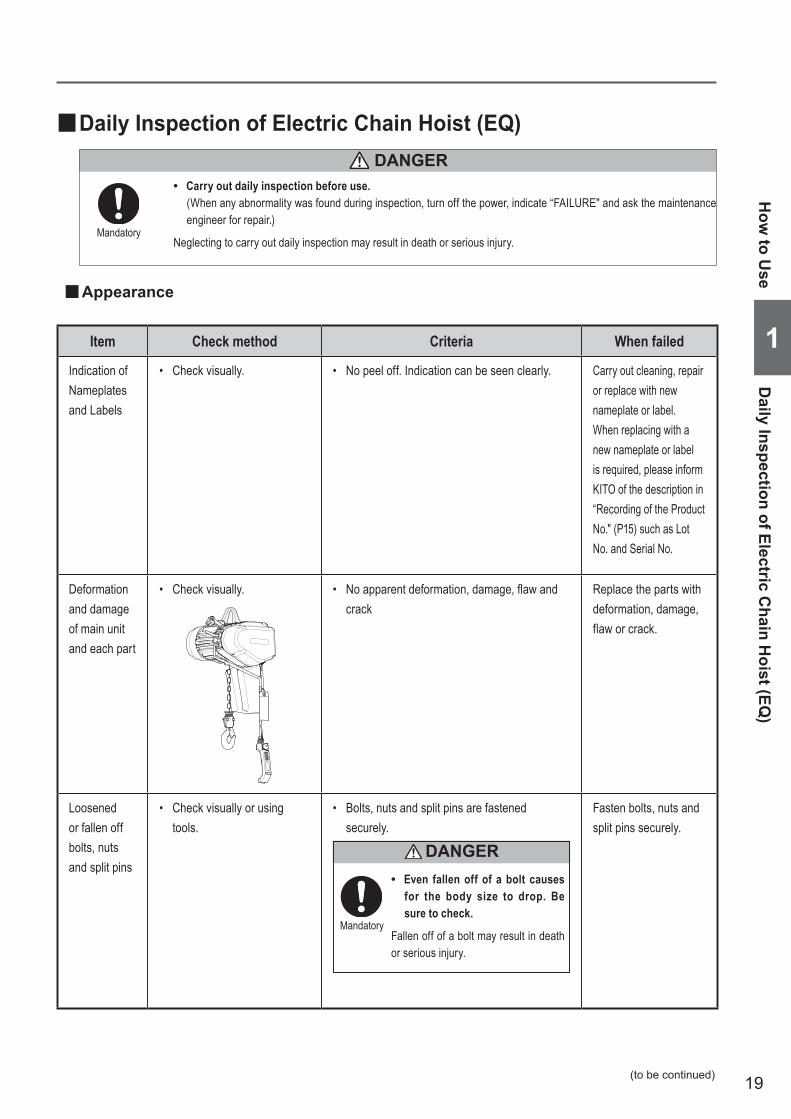
■Daily Inspection of Electric Chain Hoist (EQ)
• Carry out daily inspection before use.(When any abnormality was found during inspection, turn off the power, indicate “FAILURE" and ask the maintenance engineer for repair.)
Neglecting to carry out daily inspection may result in death or serious injury.Mandatory
■Appearance
Item Check method Criteria When failed
Indication of Nameplates and Labels
• Check visually. • No peel off. Indication can be seen clearly. Carry out cleaning, repair or replace with new nameplate or label.When replacing with a new nameplate or label is required, please inform KITO of the description in “Recording of the Product No." (P15) such as Lot No. and Serial No.
Deformation and damage of main unit and each part
• Check visually. • Noapparentdeformation,damage,flawandcrack
Replace the parts with deformation, damage, flaw or crack.
Loosened or fallen off bolts, nuts and split pins
• Check visually or using tools.
• Bolts, nuts and split pins are fastened securely.
• Even fallen off of a bolt causes for the body size to drop. Be sure to check.
Fallen off of a bolt may result in death or serious injury.
Mandatory
DANGER
Fasten bolts, nuts and split pins securely.
DANGER
How
to Use
Daily Inspection of Electric C
hain Hoist (EQ
)
1
(to be continued)
20
How to use (continued)Chapter 1 Handling the Product
1
How
to U
seD
aily
Insp
ectio
n of
Ele
ctric
Cha
in H
oist
(EQ
)
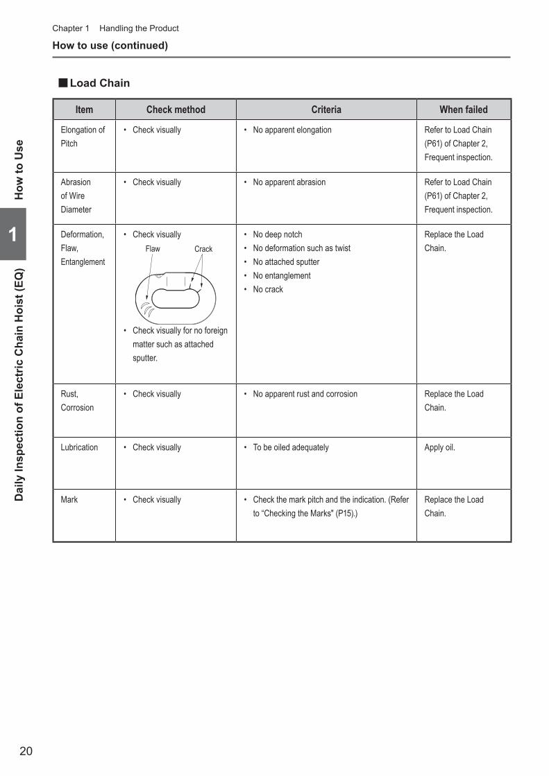
■Load Chain
Item Check method Criteria When failed
Elongation of Pitch
• Check visually • No apparent elongation Refer to Load Chain (P61) of Chapter 2, Frequent inspection.
Abrasion of Wire Diameter
• Check visually • No apparent abrasion Refer to Load Chain (P61) of Chapter 2, Frequent inspection.
Deformation, Flaw, Entanglement
• Check visuallyFlaw Crack
• Check visually for no foreign matter such as attached sputter.
• No deep notch • No deformation such as twist• No attached sputter• No entanglement• No crack
Replace the Load Chain.
Rust, Corrosion
• Check visually • No apparent rust and corrosion Replace the Load Chain.
Lubrication • Check visually • To be oiled adequately Apply oil.
Mark • Check visually • Check the mark pitch and the indication. (Refer to “Checking the Marks" (P15).)
Replace the Load Chain.

21
■Suspension Eye, Bottom Hook
Item Check method Criteria When failed
Opening of the Hook
• Check visually • No apparent opening of the Hook Carry out the inspection item of Suspension Eye and Bottom Hook (P62) of Frequent inspection.
Abrasion • Check visually • No apparent abrasion Carry out the inspection item of Suspension Eye and Bottom Hook (P62) of Frequent inspection.
Deformation, Flaw, Corrosion
• Check visually • Noapparentdeformation,flawandcorrosion Carry out the inspection item of Suspension Eye and Bottom Hook (P62) of Frequent inspection.
Hook Latch • Check visually and check the movement of the Hook Latch.
• The Hook Latch is mounted securely inside the Hook opening.
• No deformation. The Hook Latch moves smoothly.
• Do not use the Hook without the Hook Latch.
Use of the Hook without the Hook Latch may result in death or serious injury.
Prohibited
DANGER
Replace the Hook Latch.
Hook movement (Rotation)
• Check visually and rotate the Hook by hand.
• No apparent gap between the Bottom Yoke and the shank (at the neck).
• The Bottom Yoke rotates in both directions equally.
• The Bottom Yoke rotates smoothly.
Replace the Hook.
Bottom Yoke • Check visually • No loosened bolt or nut Attach the Bottom Hook to the Load Chain securely.
Neck
How
to Use
Daily Inspection of Electric C
hain Hoist (EQ
)
1
(to be continued)

22
How to use (continued)Chapter 1 Handling the Product
1
How
to U
seD
aily
Insp
ectio
n of
Ele
ctric
Cha
in H
oist
(EQ
)
■Peripheral parts of the main unit
Item Check method Criteria When failed
Chain Spring • Check visually • No apparent shrinkage or compression Carry out the inspection item of Chain Spring (P69) of Periodic inspection.
Cushion Rubber
• Check visually • No apparent shrinkage or compression• No peal off, crack of deformationof rubber
Replace the Cusion Rubber.
■Push Button Switch
Item Check method Criteria When failed
Switch set • Check visually • No deformation, damage and no loosened screw
• Label indication of the push button switch can be seen clearly.
Clean and repair the label or replace with a new label. Affix the label securely.
Rubber Steel plate

23
■Function and Performance
Item Check method Criteria When failed
Operational Check
• Press the push button and check each operation.
• The Load Chain can be wound smoothly.• The Electric chain hoist moves in the same
direction as that of the push button operation.• When the operation is stopped, the motor
stops immediately.• When the Emergency Stop Button is pressed,
all hoist motions stop.• When operating other push button while the
Emergency Stop Button is pressed, the hoist does not start operation.
• When canceling the Emergency Stop Button, the hoist operates normally.
Refer to Chapter 3 “Guidance on Troubleshooting" (P88 to 89).
Brake • Press the push button and check the operation of the Brake.
• When stopping the operation, the Brake is applied immediately and the Bottom Hook shall stop immediately. (Guideline: The travel of the Load Chain is within 2 to 3 links.)
Carry out the inspection in accordance with the items in Chapter 2 “Periodic inspection" Electromagnetic Brake (P71).
Limit Switch • Press the push button and check the operation of the Limit Switch.
• When the hoist is operated to the upper or lower limit, the motor automatically stops.
Replace the Limit Switch.Disassemble the actuator of the Limit Switch to clean.
Check for no Abnormal Sound
• Press the push button and check the operation.
Sound is also an important check point . Always be careful for the noise of the electric chain hoist.
NOTE
• No abnormal sounds and vibrations Replace the abnormal part.Apply oil on the Load Chain.
• No popping sound from the Load Chain. Check the Load Chain. (Refer to P20.)
● Check the following item with no load.
How
to Use
Daily Inspection of Electric C
hain Hoist (EQ
)
1
(to be continued)

24
How to use (continued)Chapter 1 Handling the Product
1
How
to U
seDa
ily In
spec
tion
of M
anua
l Tro
lley
(EQ
M)
■Daily Inspection of Motorized Trolley (EQM) ■ Appearance
Item Check method Criteria When failed
Indication of Nameplates and Labels
• Check visually • No peel off. Indication can be seen clearly. Clean and repair the label or replace with a new label.
Deformation and damage of each part
• Check visually • No apparent deformation, damage and corrosion
Replace the deformed or damaged part.
Loosened or fallen off bolts, nuts and split pins
• Check visually or using tools.
• Bolts, nuts and split pins are fastened securely.
• Even a drop off of a split pin may cause of drop of the main unit. Be sure to check it.
Drop off of split pin may result in death or serious injury.
Mandatory
DANGER
Fasten bolts, nuts and split pins securely.
Connection Box
FrameMotor frame
Motor cover
■Function and Performance
Item Check method Criteria When failed
Operational Check
• Press the push button to check the operation.
• To travel smoothly. No meandering and vibration.
• The electric chain hoist moves in the same direction as that of the push button operation.
• When the operation is stopped, the motor stops immediately.
• When the Emergency Stop Button is pressed, all hoist motions stop.
• When operating other push button while the Emergency Stop Button is pressed, the hoist does not start operation.
• When canceling the Emergency Stop Button, the hoist operates normally.
Refer to Chapter 3 “Guidance on Troubleshooting" (P88 to 89).
Brake • Press the push button to check the operation of the Brake.
• When the operation is stopped, the Brake is applied and the motor stops immediately.
Contact KITO.
● Check the following item with no load.

25
■Daily Inspection of Manual Trolley (EQSP) ■Appearance
Item Check method Criteria When failed
Indication of Nameplates and Labels
• Check visually • No peel off. Indication can be seen clearly. Clean and repair the label or replace with a new label.
Deformation and damage of each part
• Check visually • No apparent deformation and corrosion• No apparent deformation on the Frame
Replace the deformed or damaged part.
Loosened or fallen off bolts, nuts and split pins
• Check visually or using tools.
• Bolts, nuts and split pins are fastened securely.
• Even a drop off of a split pin may cause of drop of the main unit. Be sure to check it.
Drop off of split pin may result in death or serious injury.
Mandatory
DANGER
Fasten bolts, nuts and split pins securely.
■Function and Performance
Item Check method Criteria When failed
Operational Check
• Check the traveling motion of the electric chain hoist by moving it manually.
• To travel smoothly. No meandering and vibration.
Carry out Chapter 2 "Periodic inspection".
● Check the following item with no load.
How
to Use
Daily Inspection of M
anual Trolley (EQSP)
1
(to be continued)
26
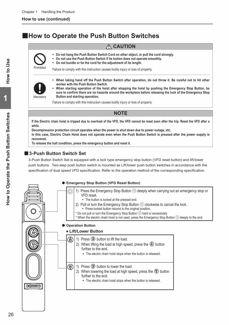
■How to Operate the Push Button Switches
● Lift/Lower Button
● Emergency Stop Button (VFD Reset Button)
● Operation Button
1) Press the Emergency Stop Button deeply when carrying out an emergency stop or VFD reset.
• The button is locked at the pressed end.2) Pull or turn the Emergency Stop Button clockwise to cancel the lock.
• Press-locked button returns to the original position.* Do not pull or turn the Emergency Stop Button hard or excessively.* When the electric chain hoist is not used, press the Emergency Stop Button deeply to the end.
1) Press button to lift the load.2) When lifting the load at high speed, press the button
further to the end. • The electric chain hoist stops when the button is released.
1) Press button to lower the load.2) When lowering the load at high speed, press the button
further to the end. • The electric chain hoist stops when the button is released.
• Do not hang the Push Button Switch Cord on other object, or pull the cord strongly. • Do not use the Push Button Switch if its button does not operate smoothly. • Do not bundle or tie the cord for the adjustment of its length.
Failure to comply with this instruction causes bodily injury or loss of property.
CAUTION
• When taking hand off the Push Button Switch after operation, do not throw it. Be careful not to hit other worker with the Push Button Switch.
• When starting operation of the hoist after stopping the hoist by pushing the Emergency Stop Button, be sure to confirm there are no hazards around the workplace before releasing the lock of the Emergency Stop Button and starting operation.
Failure to comply with this instruction causes bodily injury or loss of property.Mandatory
Prohibited
■3-Push Button Switch Set3-Push Button Switch Set is equipped with a lock type emergency stop button (VFD reset button) and lift/lower push buttons. Two-step push button switch is mounted as Lift/lower push button switches in accordance with the specification of dual speed VFD specification. Refer to the operation method of the corresponding specification.
How to use (continued)Chapter 1 Handling the Product
NOTEIf the Electric chain hoist is tripped due to overheat of the VFD, the VFD cannot be reset soon after the trip. Reset the VFD after a while.Decompression protection circuit operates when the power is shut down due to power outage, etc.In this case, Electric Chain Hoist does not operate even when the Push Button Switch is pressed after the power supply is recovered.To release the halt condition, press the emergency button and reset it.
1
How
to U
seH
ow to
Ope
rate
the
Push
But
ton
Switc
hes
27
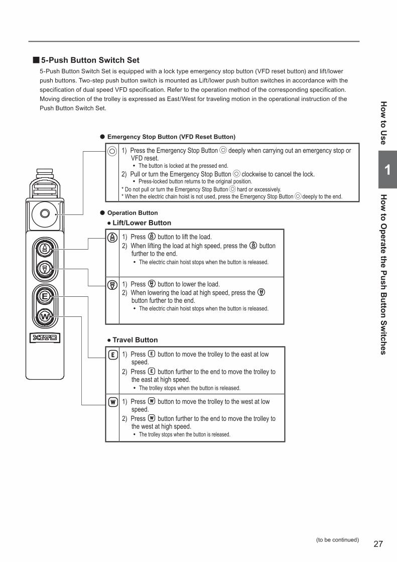
■5-Push Button Switch Set5-Push Button Switch Set is equipped with a lock type emergency stop button (VFD reset button) and lift/lower push buttons. Two-step push button switch is mounted as Lift/lower push button switches in accordance with the specification of dual speed VFD specification. Refer to the operation method of the corresponding specification. Moving direction of the trolley is expressed as East/West for traveling motion in the operational instruction of the Push Button Switch Set.
● Lift/Lower Button
● Travel Button
● Emergency Stop Button (VFD Reset Button)
● Operation Button
1) Press the Emergency Stop Button deeply when carrying out an emergency stop or VFD reset.
• The button is locked at the pressed end.2) Pull or turn the Emergency Stop Button clockwise to cancel the lock.
• Press-locked button returns to the original position.* Do not pull or turn the Emergency Stop Button hard or excessively.* When the electric chain hoist is not used, press the Emergency Stop Button deeply to the end.
1) Press button to move the trolley to the east at low speed.
2) Press button further to the end to move the trolley to the east at high speed.
• The trolley stops when the button is released.
1) Press button to move the trolley to the west at low speed.
2) Press button further to the end to move the trolley to the west at high speed.
• The trolley stops when the button is released.
1) Press button to lift the load.2) When lifting the load at high speed, press the button
further to the end. • The electric chain hoist stops when the button is released.
1) Press button to lower the load.2) When lowering the load at high speed, press the
button further to the end. • The electric chain hoist stops when the button is released.
How
to Use
How
to Operate the Push B
utton Switches
1
(to be continued)

28
How to use (continued)
■7-Push Button Switch Set7-Push Button Switch Set is equipped with a lock type emergency stop button (VFD reset button) and lift/lower pushbuttons. One-step push button switch or two-step push button switch is mounted as Lift/lower push button switchesin accordance with the specification of single speed or dual speed VFD specification. Refer to the operation methodof the corresponding specification.Moving directions of the trolley are expressed as East/West for traveling motion, and North/South for traversalmotion in the operational instruction of the Push Button Switch Set.
● Traverse Button
● Lift/Lower Button
● Travel Button
● Emergency Stop Button (VFD Reset Button)
Single Speed Model Dual Speed VFD Model
1) Press button to move the trolley to the south.
• The trolley stops when the button is released.
1) Press button to move the trolley to the south at low speed.
2) Press button further to the end to move the trolley to the south at high speed.
• The trolley stops when the button is released.
1) Press button to move the trolley to the north.
• The trolley stops when the button is released.
1) Press button to move the trolley to the north at low speed.
2) Press button further to the end to move the trolley to the north at high speed.
• The trolley stops when the button is released.
1) Press button to move the trolley to the east at low speed.2) Press button further to the end to move the trolley to the east at high speed.
• The trolley stops when the button is released.
1) Press button to move the trolley to the west at low speed.2) Press button further to the end to move the trolley to the west at high speed.
• The trolley stops when the button is released.
1) Press the Emergency Stop Button deeply when carrying out an emergency stop or VFD reset.
• The button is locked at the pressed end.2) Turn the Emergency Stop Button clockwise to cancel the lock.
• Press-locked button returns to the original position.* Do not pull or turn the Emergency Stop Button hard or excessively.* When the electric chain hoist is not used, press the Emergency Stop Button deeply to the end.
1) Press button to lift the load.2) When lifting the load at high speed, press the button further to the end.
• The electric chain hoist stops when the button is released.
1) Press button to lower the load.2) When lowering the load at high speed, press the button further to the end.
• The electric chain hoist stops when the button is released.
Chapter 1 Handling the Product
1
How
to U
seH
ow to
Ope
rate
the
Push
But
ton
Switc
hes
Dual
Dual

29
■Operation ■General
• Do not operate the electric chain hoist in an environment with flammable or explosive gas.The electric chain hoist is not designed as explosion proof specification.
• Do not use the electric chain hoist exceeding the ratings (intermittent rating) of the lifting motor and the maximum start-up frequency.
• Do not use the electric chain hoist by the voltage other than the rated voltage. • Do not use the Emergency Stop Button for ordinary stop operation. • Do not expose the Load Chain to sparks from welding. • Do not contact welding rods or electrodes with the Load Chain. • Do not use the Load Chain as the earth for welding work. (Fig. A)
Failure to comply with these instructions may result in death or serious injury.
Prohibited
A
• Follow the operating environment and conditions for the electric chain hoist.
Failure to comply with this instruction may result in death or serious injury.
Mandatory
■Slinging
• Do not apply a load to the tip of the Bottom Hook or the Hook Latch. (Fig. B) • Do not bind a load with the Load Chain directly. (Fig. C) • Do not operate the Load Chain while it is in
contact with any sharp edges. (Fig. D)
Failure to comply with these instructions may result in death or serious injury.
Prohibited
• Use the sling appropriate for the weight and shape of a load.Inappropriate slinging may result in danger such as drop of a lifted load.
• Carry out the slinging with equal load on slinging devices for stable lifting of a load. • Attach the slinging devices securely to a load. • Attach the slinging devices to the Bottom Hook correctly.
Failure to comply with these instructions may result in death or serious injury.
Mandatory
CB D
How
to Use
Operation
1
(to be continued)
DANGER
DANGER

30
How to use (continued)
■Lifting/Lowering
• Do not lift more than the capacity. (Fig. E)The capacity is indicated in the nameplate.
• Do not operate the electric chain hoist exceeding the lifting height. • Do not dare to lift the structure or any other object supposed to be difficult to lift. • Do not lift a load at no-load side of the Load Chain. • Do not stop the electric chain hoist with the limit switch (over winding prevention device). • Do not use the electric chain hoist when the Friction Clutch (overload prevention
device) is operated to stop winding. • Do not lift or lower excessively.
• Do not remove the Chain Spring to operate the limit switch by hitting the body size with the Bottom Hook. If such stop operation is repeated, it may result in breaking of the Load Chain.
• Do not hit the body size with the End Stopper of the Load Chain to cause the operation of the Friction Clutch. If such operation is repeated, it may result in breaking of the Load Chain.
• Do not use the main unit as a fulcrum. (Fig. F) • Do not swing the lifted load. • Do not wind the slack Load Chain with a load in one action to avoid exposing the
Load Chain to shock.Stop lifting when the Load Chain is stretched tight. Then lift slowly.
• Do not carry out reverse operation while lifting/lowering a load.When reversing the motion, stop the electric chain hoist and then reverse the motion.
• Do not carry out excessively frequent inching. • Do not carry out plugging.
When reversing the motion, stop the electric chain hoist and then reverse the motion. • When lifting off a load from a pallet, lift the load to avoid exposing to shock, such as
the load falling. (Fig. G) • Do not cause the load to come into contact with the Load Chain. • Do not rotate a lifted load. Use the device for rotation. • Do not carry out the welding or cutting work on a lifted load. • Do not repair or disassemble a lifted load.
When repairing or disassembling an electric chain hoist, ensure that the product is placed down on the floor and that only maintenance engineers maintain the electric chain hoist.
• Do not enter beneath a lifted load. • Do not hit the Chain Container with a load or slinging devices.
Otherwise the Load Chain in the Chain Container falls out of the bucket to cause injury. • Do not leave from the operating position while a load is lifted. Watch the lifted load.
Failure to comply with these instructions may result in death or serious injury.
Prohibited
• When the limit switch (over winding prevention device) is operated, stop the lifting work immediately and lower the load.
• Move the electric chain hoist right above the load and then lift the load. (Do not lift the load in an inclined direction.) (Fig. H)
Failure to comply with these instructions may result in death or serious injury.
Mandatory
over load
E
F
G
H
Chapter 1 Handling the Product
1
How
to U
seO
pera
tion
DANGER
31
• Do not use the Friction Clutch to measure the weight of a load.
The use of the Friction Clutch other than intended purpose may result in injury or property damage.
Prohibited
• When carrying a lifted load using a lifting magnet or a vacuum chuck, lower the height of the lifted load as low as possible.
• When lifting a load with two electric chain hoists, use the electric chain hoist with the rated lifting capacity of a single hoist exceeding the load.
• When lifting a load with two electric chain hoists, use the electric chain hoists of the same model and capacity and operate the respective electric chain hoist to keep the load lifted or lowered horizontal.
Failure to comply with this instruction causes bodily injury or loss of property.
Mandatory
CAUTION
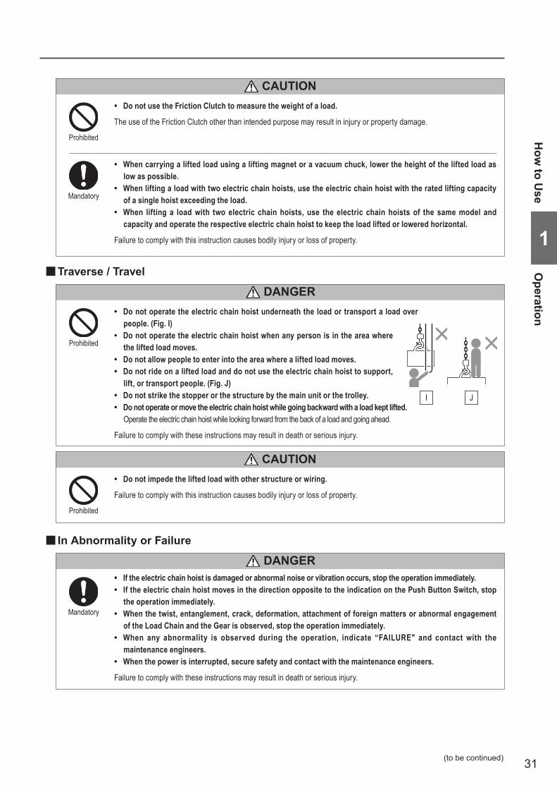
■ In Abnormality or Failure
• If the electric chain hoist is damaged or abnormal noise or vibration occurs, stop the operation immediately. • If the electric chain hoist moves in the direction opposite to the indication on the Push Button Switch, stop
the operation immediately. • When the twist, entanglement, crack, deformation, attachment of foreign matters or abnormal engagement
of the Load Chain and the Gear is observed, stop the operation immediately. • When any abnormality is observed during the operation, indicate “FAILURE" and contact with the
maintenance engineers. • When the power is interrupted, secure safety and contact with the maintenance engineers.
Failure to comply with these instructions may result in death or serious injury.
Mandatory
• Do not impede the lifted load with other structure or wiring.
Failure to comply with this instruction causes bodily injury or loss of property.
Prohibited
CAUTION
■Traverse / Travel
• Do not operate the electric chain hoist underneath the load or transport a load over people. (Fig. I)
• Do not operate the electric chain hoist when any person is in the area where the lifted load moves.
• Do not allow people to enter into the area where a lifted load moves. • Do not ride on a lifted load and do not use the electric chain hoist to support,
lift, or transport people. (Fig. J) • Do not strike the stopper or the structure by the main unit or the trolley. • Do not operate or move the electric chain hoist while going backward with a load kept lifted.
Operate the electric chain hoist while looking forward from the back of a load and going ahead.
Failure to comply with these instructions may result in death or serious injury.
Prohibited
I J
How
to Use
Operation
1
(to be continued)
DANGER
DANGER
32
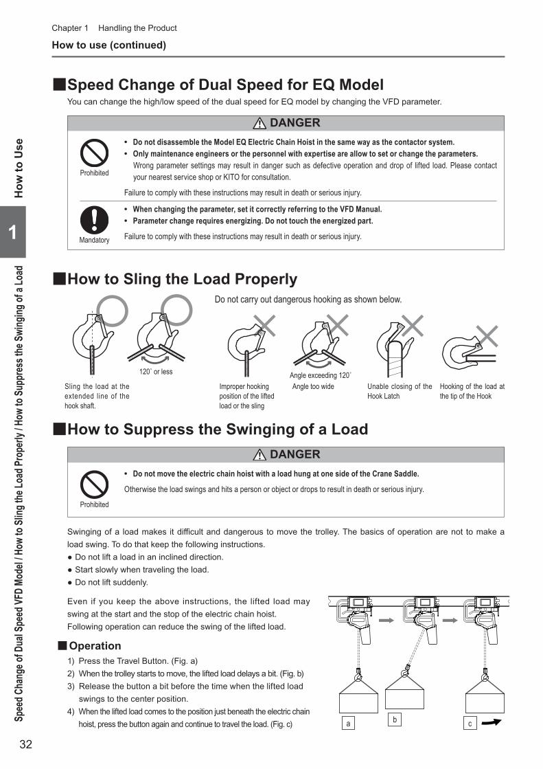
Angle exceeding 120˚120˚ or less
Do not carry out dangerous hooking as shown below.
Sling the load at the extended line of the hook shaft.
Improper hooking position of the lifted load or the sling
Angle too wide Unable closing of the Hook Latch
Hooking of the load at the tip of the Hook
■How to Sling the Load Properly
■How to Suppress the Swinging of a Load
• Do not move the electric chain hoist with a load hung at one side of the Crane Saddle.
Otherwise the load swings and hits a person or object or drops to result in death or serious injury.
Prohibited
Swinging of a load makes it difficult and dangerous to move the trolley. The basics of operation are not to make a load swing. To do that keep the following instructions.
● Do not lift a load in an inclined direction. ● Start slowly when traveling the load. ● Do not lift suddenly.
Even if you keep the above instructions, the lifted load may swing at the start and the stop of the electric chain hoist.Following operation can reduce the swing of the lifted load.
■Operation1) Press the Travel Button. (Fig. a)2) When the trolley starts to move, the lifted load delays a bit. (Fig. b)3) Release the button a bit before the time when the lifted load
swings to the center position.4) When the lifted load comes to the position just beneath the electric chain
hoist, press the button again and continue to travel the load. (Fig. c)
How to use (continued)Chapter 1 Handling the Product
■Speed Change of Dual Speed for EQ ModelYou can change the high/low speed of the dual speed for EQ model by changing the VFD parameter.
• Do not disassemble the Model EQ Electric Chain Hoist in the same way as the contactor system. • Only maintenance engineers or the personnel with expertise are allow to set or change the parameters.
Wrong parameter settings may result in danger such as defective operation and drop of lifted load. Please contact your nearest service shop or KITO for consultation.
Failure to comply with these instructions may result in death or serious injury.
Prohibited
Mandatory
• When changing the parameter, set it correctly referring to the VFD Manual. • Parameter change requires energizing. Do not touch the energized part.
Failure to comply with these instructions may result in death or serious injury.1
How
to U
seSp
eed C
hang
e of D
ual S
peed
VFD
Mod
el / H
ow to
Slin
g the
Load
Pro
perly
/ How
to S
uppr
ess t
he S
wing
ing of
a Lo
ad
DANGER
DANGER
ba c

33
Do not wind the slack Load Chain with a load in one action to avoid exposing the Load Chain to shock.
Stop lifting when the Load Chain is stretched tight. Then lift slowly.Prohibited
DANGER
Prohibited
CAUTION • Do not store the electric chain hoist at a state of over lifting or over lowering.
Failure to comply with these instructions causes bodily injury or loss of property.
NOTE • Clean the push button switches always not to allow the dust, sands and oil attach. • When storing the electric chain hoist for a long period, it is effective to prevent rusting to operate it at a certain period
without load. • When putting the electric chain hoist on a floor, remove the Chain Container.
Otherwise the Chain Container may deform or be damaged. • When not using the electric chain hoist, wind up the Bottom Hook to the height not to hinder persons passing by or other work. • Decide the place to store the electric chain hoist in advance. It is recommended to hang the push button cable on the pillar.
■Precautions After Work
■Setting Up the No-Load High-Speed FunctionThe EQ Series Electric Chain Hoist provides the no-load high-speed function. When you enable this function, operation is automatically switched to 1.3 times faster than high-speed during high-speed operation if a load is between no-load and 30% of rated load. This function is set to enable in the factory-preset mode.
■Enabling/Disabling the No-Load High-Speed FunctionTo enable or disable the no-load high-speed function setting, use push button switches.
• Store the electric chain hoist with power off. • Indicate “FAILURE" on the electric chain hoist that needs repair not to be used. • Wipe off dust and waterdrop, apply oil at the neck of the Hook and the Load Chain and store the hoist. • Remove the stain, attached foreign matter and waterdrop from the parts such as the Limit Switch and the
Chain Container that is scratched by the Load Chain and stored it. • When the electric chain hoist is installed outdoor, cover it with rain cover or roof after application of rust
proof process.
Failure to comply with these instructions causes bodily injury or loss of property.
Mandatory
How
to Use
Precautions After W
ork
1
(to be continued)
● To enable the no-load high-speed function1. Perform lowering operation to activate
the lower limit switch.2. Press the emergency stop button.3. Press and hold the first row of the
lowering button (low-speed) for 5 seconds or more.
4. Release the emergency stop button.
● To disable the no-load high-speed function1. Perform lowering operation to activate
the lower limit switch.2. Press the emergency stop button.3. Press and hold the second row of the
lowering button (high-speed) for 5 seconds or more.
4. Release the emergency stop button.
When you use the no-load high-speed function for the first time and when you set it to enabled, confirm that operation is automatically switched to1.3 times speed during high-speed operation.
Failure to comply with these instructions may result in bodily injury or property damage.Mandatory
CAUTION

34
Chapter 1 Handling the Product
Work Flow of Assembling and InstallationThe contents of the work to assemble and install the product by the maintenance engineers and installer are described from this page and after. To eliminate the redo work and for effective assembling and installation, please check the following work flow first and then start assembling and installation work.
Mode
l Che
ckAs
sem
blin
gIn
stall
atio
nCh
eck aft
er Inst
allation
Suspended Type (hoist only) Trolley Type
Installation of Suspended Type (hoist only) (P50) Installation of Trolley Combined Model (P51 to 53)
Assembling Parts to Electric Chain Hoist (P35)
Checking Power and Power Cables (P45)
Combination with the Motorized Trolley (P38) Combination with the Manual Trolley (P42)
Motorized Trolley Type Manual Trolley Type
Connecting Cables Connecting Cables Connecting Cables
PreparationMounting the Chain ContainerLubrication on the Load ChainChecking gear oil
Connecting Power Cable to the powerMounting the Hoist to the Travel RailMounting the StopperPower Cable Layout for Motorized/Manual trolley type Case for cable hanger Case for T-shape/angle type hanger
Connecting Power Cable to the power
Checking installation method and place
125kg to 1t Connecting the Relay Cable Connecting the Trolley Power Cable Connecting the Trolley Push Button Cord
125kg to 1t Connecting the Power Cable Connecting the Push Button Switch Cord
Checking the power Checking the breaker ratings
Checking the Power Cable Permissible cable length and size
Checking and Carrying Out “Check Items” (P54)
EQMEQ
EQSP
Carrying Out Operational Check (P54)
Motorized Trolley Type (P48)
125kg to 1t Connecting the Power Cable Connecting Push Button Switch Set Cord
Suspended Model (hoist only) (P47) Manual Trolley Type (P49)
Part replacement of the electric chain hoistChecking the rail width of the motorized
trolleyChecking the number and position of
adjusting spacersCombination of the electric chain hoist and
the motorized trolleyMounting the balance weight
Part replacement of the electric chain hoistChecking the rail width of the manual trolleyChecking the number and position of
adjusting spacersCombination of the electric chain hoist and
the manual trolley
1
Wor
k Flo
w of
Ass
embl
ing
and
Inst
allat
ion

35
• The each type of Chain Container has the capacity to store the specific amount of the Load Chain. Use correct capacity of the Chain Container.When storing the Load Chain of which amount exceeds the capacity of the Chain Container, it may result in death or serious injury due to the flow over of the Load Chain from the Chain Container or defective operation of the electric chain hoist.Improper combination of the Chain Container and the electric chain hoist is very dangerous because of the possibility of drop of the Chain Container.The seal to indicate the capacity and lifting height is attached on the Chain Container. Check it before use.
• If the Chain Container is not assembled correctly, it may result in death or serious injury due to a drop of the Chain Container or Load Chain, and malfunction of the Electric Chain Hoist.Refer to the assembling instruction on the page 38 and assemble the Chain Container correctly.
Failure to comply with these instructions causes bodily injury or loss of property.
Mandatory
Assembling
• Only maintenance engineers or the personnel with expertise are allowed to assemble and disassemble the electric chain hoist.
Assembling or disassembling of the electric chain hoist may result in death or serious injury.Prohibited
■Assembling Parts to Electric Chain Hoist ■Preparation for Assembling• Hang the electric chain hoist body size to facilitate the mounting of the Chain Container.• Check that the stopper and the cushion rubber are mounted at the link third from the no load side of the Load
Chain (the end without the Bottom Hook).
■Mounting the Chain ContainerThe Chain Container is made of plastic. (Canvas container is available as an option.)
• When storing the Load Chain into the Chain Container, put the chain end with no-load side first and then store the rest of the Load Chain.
Failure to comply with these instructions causes bodily injury or loss of property.Mandatory
CAUTION
Assem
blingA
ssembling Parts to Electric C
hain Hoist
1
(to be continued)
DANGER
DANGER

36
Assembling (continued)Chapter 1 Handling the Product
1
Ass
embl
ing
Ass
embl
ing
Part
s to
Ele
ctric
Cha
in H
oist
● Assembling the Chain Container
1) Pass a Socket Bolt through all holes of the Chain Container, the Body and the Chain Container, in this order to mount the Chain Container.
2) Screw the U nut into the Scoket bolt and tighten it securely.
• The Socket Bolt must protrude from the end face of the nut by three threads or more.
Assembly figure
Name of each part
Body
Three threads or more
Chain Container
Socket Bolt
Body
U nut

37
Assem
blingA
ssembling Parts to Electric C
hain Hoist
1
■Oiling the Load Chain
■Gear OilInside of the Gear Case is filled with gear oil at the shipping. The level of the oil filled with specified amount comes to the height of the inspection hole. Check the oil level visually.
● Cheking the Gear Oil Amount
1) Remove the Oil Plug on the upper Main Body
2) Insert the check bar from the Oil check hole to check the oil level.
(The normal distance between the hole and the oil level is between 107 to 111 mm for the body size D, and 101 to 105 mm for the body size C.)
• Be sure to apply lubricant on the Load Chain. Do not carry out oiling work in the place near the fire or arc.
Otherwise it will result in fire.
Mandatory
• Use genuine gear oil.
Use of the gear oil other than the genuine oil (including mixed use) will result in death or serious injury due to the drop of the lifted load.Mandatory
Load
Applied position
● Remove dust and waterdrops attached on the Load Chain and then apply lubricant. Application of lubricant influences on the life of the Load Chain considerably. Apply the lubricant sufficiently.Use the following genuine lubricant.• Epinoc Grease AP (N)0 (Nippon Oil Corporation)• Consistency No.0 (Industrial general lithium grease)
● Release all loads from the Load Chain and apply the lubricant all over the Load Chain.After application of the lubricant lift/lower the electric chain hoist without load to spread the lubricant on the Load Chain.
DANGER
DANGER
(to be continued)
Distance to the oil surface
Oil check hole
Oil surface
Oil plug
38
Chapter 1 Handling the Product
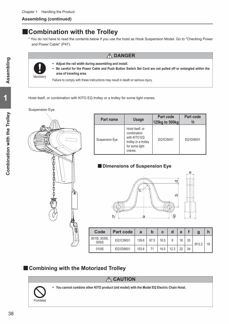
■Combination with the Trolley* You do not have to read the contents below if you use the hoist as Hook Suspension Model. Go to "Checking Power
and Power Cable" (P47).
• Adjust the rail width during assembling and install. • Be careful for the Power Cable and Push Button Switch Set Cord are not pulled off or entangled within the
area of traveling area.
Failure to comply with these instructions may result in death or serious injury.Mandatory
1
Ass
embl
ing
Com
bina
tion
with
the
Trol
ley
DANGER
Assembling (continued)
Hoist itself, or combination with KITO EQ trolley or a trolley for some light cranes.
Suspension Eye
Part name Usage Part code125kg to 500kg
Part code1t
Suspension Eye
Hoist itself, or combination with KITO EQ trolley or a trolley for some light cranes.
EQ1CI9001 EQ1DI9001
■Dimensions of Suspension Eye
Code Part code a b c d e f g h001IS, 003IS,
005IS EQ1CI9001 139.6 67.5 16.5 8 16 33Ø12.2 16
010IS EQ1DI9001 153.6 71 16.5 12.3 22 34
gah
c
de
b
if
■Combining with the Motorized Trolley
CAUTION • You cannot combine other KITO product (old model) with the Model EQ Electric Chain Hoist.
Prohibited

39
■Checking the Number of the Assembled Adjusting Spacers and Their Positions (for Motorized Trolley)When installing a trolley to the beam, the length of the Suspension Shaft (width between frames) must be adjusted in accordance with the rail width.Wrong number of wrong position of Spacers may result in the drop of the electric chain hoist.Insert the correct number of Spacers with correct ratings and for rail width at the correct position, referring to the following table.
Assem
blingC
ombining w
ith the motorized trolley
1
(Unit: piece)
Capacity Parts Name
Rail width (mm) 58 66 74 82 90 91 98 106 113 119 125 131 137 143
125kg250kg500kg
Thinspacer
Inner 1+2 2+3 4+4 6+2 7+3 7+3 4+1 6+2 7+3 7+5 8+5 6+5 7+6 7+4Outer 13 11 8 8 6 6 11 8 6 4 3 5 3 5
Thickspacer
Inner 0+0 0+0 0+0 0+1 0+1 0+1 1+2 1+2 1+2 1+2 1+2 2+2 2+2 2+3Outer 6 6 6 5 5 5 3 3 3 3 3 2 2 1
Fixing spacer (300)
Inner - - - - - - - - - - - - - -Outer - - - - - - - - - - - - - -
Thick spacer L
Inner - - - - - - - - - - - - - -Outer - - - - - - - - - - - - - -
Thinspacer L Inner 1+1 1+1 1+1 1+1 1+1 1+1 1+1 1+1 1+1 1+1 1+1 1+1 1+1 1+1
Capacity Parts Name
Rail width (mm) 144 149 155 163 170 178 185 200 201 204 210 220 240 260
125kg250kg500kg
Thinspacer
Inner 7+4 8+5 9+6 7+6 3+0 4+1 2+2 4+4 0+1 1+1 2+2 3+4 2+3 2+2Outer 5 3 1 3 5 3 4 0 7 6 4 1 3 4
Thickspacer
Inner 2+3 2+3 2+3 3+3 3+4 3+4 0+0 0+0 1+1 1+1 1+1 1+1 2+2 3+3Outer 1 1 1 0 2 2 9 9 7 7 7 7 5 3
Fixing spacer (300)
Inner - - - - 0+0 0+0 1+1 1+1 1+1 1+1 1+1 1+1 1+1 1+1Outer - - - - 2 2 0 0 0 0 0 0 0 0
Thick spacer L
Inner - - - - 1+1 1+1 1+1 1+1 1+1 1+1 1+1 1+1 1+1 1+1Outer - - - - 0 0 0 0 0 0 0 0 0 0
Thinspacer L Inner 1+1 1+1 1+1 1+1 1+1 1+1 1+1 1+1 1+1 1+1 1+1 1+1 1+1 1+1
Capacity Parts Name
Rail width (mm) 280 300 305
125kg250kg500kg
Thinspacer
Inner 1+1 4+1 4+2Outer 6 3 2
Thickspacer
Inner 4+4 4+5 4+5Outer 1 0 0
Fixing spacer (300)
Inner 1+1 1+1 1+1Outer 0 0 0
Thick spacer L
Inner 1+1 1+1 1+1Outer 0 0 0
Thinspacer L Inner 1+1 1+1 1+1
0+10: the number of spacers on the Frame G side of the shaft1: the number of spacers on the Frame S side of the shaft
(125kg to 1t)
(to be continued)
Rail width of 58 – 163 (mm): Normal suspension shaft;Rail width of 170 – 305 (mm): Wide-frange suspension shaft
(164 mm is optional);
● 125kg to 500kg
Suspension eye
Thinspacer
Thinspacer
Thinspacer
Thickspacer
Thickspacer
Thickspacer
Frame S
Thinspacer L
Thinspacer L
Thick spacer L(125kg to 500kg)
Thick spacer L(125kg to 500kg)
Fixingspacer(300)
Fixingspacer(300)
Fixingspacer
Frame G
Inner Outer

40
Assembling (continued)Chapter 1 Handling the Product
1
Ass
embl
ing
Com
bini
ng w
ith th
e m
otor
ized
trol
ley
■Length of Adjusting Spacer
A
BC
(Unit: mm)
125kg, 250kg, 500kg, 1t
Thick spacerA 12.5B 38.4C 32
Thick spacer LA 12.5B 45C 32
Fixing spacer (300)A 50B 38.4C 32
Thin spacer LFor Beam width:
58-163mm
A 3.2B 50.8C 32.8
Thin spacer LFor Beam width:
164-305mm
A 5.5B 50.8C 32.8
Thin spacerA 3.2B 38.4C 32
Suspension shaft diameter 31
(Unit: piece)
Capacity Parts Name
Rail width (mm) 58 66 74 82 90 91 98 106 113 119 125 131 137 143
1t
Thinspacer
Inner 0+1 1+2 3+3 5+1 6+2 6+2 3+0 5+1 6+2 7+3 7+4 5+4 6+5 6+3Outer 13 11 8 8 6 6 11 8 6 4 3 5 3 5
Thickspacer
Inner 0+0 0+0 0+0 0+1 0+1 0+1 1+2 1+2 1+2 1+2 1+2 2+2 2+2 2+3Outer 6 6 6 5 5 5 3 3 3 3 3 2 2 1
Fixing spacer (300)
Inner - - - - - - - - - - - - - -Outer - - - - - - - - - - - - - -
Thinspacer L Inner 1+1 1+1 1+1 1+1 1+1 1+1 1+1 1+1 1+1 1+1 1+1 1+1 1+1 1+1
Capacity Parts Name
Rail width (mm) 144 149 155 163 170 178 185 200 201 204 210 220 240 260
1t
Thinspacer
Inner 6+3 7+4 8+5 6+5 6+3 7+4 5+5 7+7 3+4 4+4 5+5 6+7 5+6 5+5Outer 5 3 1 3 5 3 4 0 7 6 4 1 3 4
Thickspacer
Inner 2+3 2+3 2+3 3+3 3+4 3+4 0+0 0+0 1+1 1+1 1+1 1+1 2+2 3+3Outer 1 1 1 0 2 2 9 9 7 7 7 7 5 3
Fixing spacer (300)
Inner - - - - 0+0 0+0 1+1 1+1 1+1 1+1 1+1 1+1 1+1 1+1Outer - - - - 2 2 0 0 0 0 0 0 0 0
Thinspacer L Inner 1+1 1+1 1+1 1+1 1+1 1+1 1+1 1+1 1+1 1+1 1+1 1+1 1+1 1+1
Capacity Parts Name
Rail width (mm) 280 300 305
1t
Thinspacer
Inner 4+4 7+4 7+5Outer 6 3 2
Thickspacer
Inner 4+4 4+5 4+5Outer 1 0 0
Fixing spacer (300)
Inner 1+1 1+1 1+1Outer 0 0 0
Thinspacer L Inner 1+1 1+1 1+1
0+10: the number of spacers on the Frame G side of the shaft1: the number of spacers on the Frame S side of the shaft
Rail width of 58 – 163 (mm): Normal suspension shaft;Rail width of 170 – 305 (mm): Wide-frange suspension shaft
(164 mm is optional);
● 1t

41
Assem
blingC
ombining w
ith the motorized trolley
1
■Combination of the Electric Chain Hoist and the Motorized Trolley
● 125kg to 1t
1) Fix the Suspension Shaft to the Frame G with a Suspension Shaft Bolt, a slotted nut and a split pin.
● When fixing the Frame S and the Suspension Shaft, use the hole A. If the gap between the rail end and the wall of the housing is scarce to install the electric chain hoist to the travel rail, use the hole B. (Refer to “Mounting the Hoist to the Travel Rail" (P51).)
• Use new split pins. After insertion, bend the pin securely at its both ends.
Use of old split pins may result in death or serious injury due to drop.
Mandatory
• The hole B on the Suspension Shaft is the hole for mounting work (temporary assembly). Do not use the hole for the adjustment of rail width.
Failure to comply with this instruction may result in death or serious injury.
Prohibited
DANGER
DANGER
2) Set the Suspension Shaft with a Thin Spacer, Thick Spacer, Fixing Spacers, Thick Spacer L and a Thin Spacer L.
3) Hook the Suspension eye on the Suspension Shaft.
4) Set the Suspension Shaft with another Thin Spacer, Thick Spacer, Fixing Spacers, Thick Spacer L and Thin Spacer L. Then insert the Suspension Shaft into the Frame S.
• Adjust the Spacers in accordance with the rail width. (Refer to “Checking the Number of the Assembled Adjusting Spacers and Their Positions" (P39, 40) for the number of Spacers.)
5) Set the Suspension Shaft with a Thick Spacer. Insert the Shaft Stopper Pin into the Hole A and fix it with a split pin.
• Insert the Shaft Stopper Pin in the direction that the split pin comes to the left when viewed from the front side of the MR2Q Connection Box.
Frame G
Suspension Shaft BoltSuspension ShaftSplit pin
Slotted nut
Hole for standard rail width
<Suspension Shaft>
Hole for standard rail width Hole A Hole B
Frame GThin spacer
Thick spacerFixing spacer
Suspension ShaftSplit pin
Thick spacer LFixing spacer
Thick spacer LThin spacer L
Thick spacer
Thin spacer
Frame S
Suspension eye
Slotted nut
Fixing spacer
Thin spacer
Thick spacerSplit pin
Shaft Stopper Pin
Shaft Bolt
Hole BHole A
Thin spacer L

42
Chapter 1 Handling the Product
1
Ass
embl
ing
Com
bina
tion
with
the
Man
ual T
rolle
y
■Checking the Number of the Assembled Adjusting Spacers and Their Positions (for Manual Trolley)When installing a trolley to the beam, the length of the Suspension Shaft (width between frames) must be adjusted in accordance with the rail width.Wrong number of wrong position of Spacers may result in the drop of the electric chain hoist. Insert the correct number of Spacers with correct ratings and for rail width at the correct position, referring to the following table.
(Unit: piece)Capacity Parts
NameRail width (mm)
Plain Trolley 50 58 66 74 82 90 91 98 106 113 119 125 131 137 143 144 149 155 163
125kg250kg500kg
Thin spacer
Inner 2+3 4+4 1+1 2+4 3+4 1+1 1+1 2+2 3+4 4+5 1+2 2+3 3+4 0+1 1+2 1+2 2+3 3+4 4+5Outer 7 4 10 7 5 10 10 8 5 3 9 7 5 11 9 9 7 5 3
Thickspacer
Inner 0+0 0+0 1+1 1+1 1+1 2+2 2+2 2+2 2+2 2+2 3+3 3+3 3+3 4+4 4+4 4+4 4+4 4+4 4+4Outer 8 8 6 6 6 4 4 4 4 4 2 2 2 0 0 0 0 0 0
Thick spacer L
Inner 1+1 1+1 1+1 1+1 1+1 1+1 1+1 1+1 1+1 1+1 1+1 1+1 1+1 1+1 1+1 1+1 1+1 1+1 1+1Outer 0 0 0 0 0 0 0 0 0 0 0 0 0 0 0 0 0 0 0
Fixing spacer (25) Inner - - - - - - - - - - - - - - - - - - -
1t
Thin spacer
Inner - 3+4 0+1 2+2 3+3 0+1 0+1 1+2 3+3 4+4 1+1 2+2 3+3 0+0 1+1 1+1 2+2 3+3 4+4Outer - 4 10 7 5 10 10 8 5 3 9 7 5 11 9 9 7 5 3
Thickspacer
Inner - 0+0 1+1 1+1 1+1 2+2 2+2 2+2 2+2 2+2 3+3 3+3 3+3 4+4 4+4 4+4 4+4 4+4 4+4Outer - 8 6 6 6 4 4 4 4 4 2 2 2 0 0 0 0 0 0
Thick spacer L
Inner - 1+1 1+1 1+1 1+1 1+1 1+1 1+1 1+1 1+1 1+1 1+1 1+1 1+1 1+1 1+1 1+1 1+1 1+1Outer - 0 0 0 0 0 0 0 0 0 0 0 0 0 0 0 0 0 0
Fixing spacer (38) Inner - - - - - - - - - - - - - - - - - - -
Capacity Parts Name
Rail width (mm)Plain Trolley 170 178 185 200 201 204 210 220 240 260 280 300 305
125kg250kg500kg
Thin spacer
Inner 0+0 1+1 2+2 0+1 1+1 1+2 2+2 4+4 3+3 2+2 1+2 4+5 2+5Outer 9 7 5 8 7 6 5 1 3 5 6 0 2
Thickspacer
Inner 3+3 3+3 3+3 4+4 4+4 4+4 4+4 4+4 5+5 6+6 7+7 7+7 8+7Outer 9 9 9 7 7 7 7 7 5 3 1 1 0
Thick spacer L
Inner 1+1 1+1 1+1 1+1 1+1 1+1 1+1 1+1 1+1 1+1 1+1 1+1 1+1Outer 0 0 0 0 0 0 0 0 0 0 0 0 0
Fixing spacer (25) Inner 1+1 1+1 1+1 1+1 1+1 1+1 1+1 1+1 1+1 1+1 1+1 1+1 1+1
1t
Thin spacer
Inner 0+0 1+1 2+2 0+1 1+1 1+2 2+2 4+4 3+3 2+2 1+2 4+5 2+5Outer 9 7 5 8 7 6 5 1 3 5 6 0 2
Thickspacer
Inner 2+2 2+2 2+2 3+3 3+3 3+3 3+3 3+3 4+4 5+5 6+6 6+6 7+6Outer 9 9 9 7 7 7 7 7 5 3 1 1 0
Thick spacer L
Inner 1+1 1+1 1+1 1+1 1+1 1+1 1+1 1+1 1+1 1+1 1+1 1+1 1+1Outer 0 0 0 0 0 0 0 0 0 0 0 0 0
Fixing spacer (38) Inner 1+1 1+1 1+1 1+1 1+1 1+1 1+1 1+1 1+1 1+1 1+1 1+1 1+1
Assembling (continued)
■Combination with the Manual Trolley
Rail width of 58 – 163 (mm): Normal suspension shaft;Rail width of 164 – 305 (mm): Wide-frange suspension shaft
(optional);
* Description for spacers;For example, "0+1"
0: the number of spacers on the frame G side.1: the number of spacers on the frame S side.
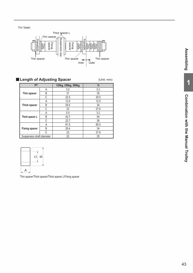
43
Assem
blingC
ombination w
ith the Manual Trolley
1 ■Length of Adjusting Spacer
A
BC
PT 125kg, 250kg, 500kg 1t
Thin spacerA 3.2 3.2B 31 35C 22.5 25.5
Thick spacerA 12.5 12.5B 29.4 34C 23 27.6
Thick spacer LA 5.5 3.2B 42.7 54C 22.7 26
Fixing spacerA 81.5 80.5B 29.4 34C 23 27.6
Suspension shaft diameter 22 25
Thin spacer/Thick spacer/Thick spacer L/Fixing spacer
(Unit: mm)
FrameS
(G)
FrameS
N
ThickspacerThick
spacerThick
spacer
Thickspacer
Thickspacer
Fixingspacer
Fixingspacer
Suspension eye
Thin spacer Thin spacer Thin spacer
Thin spacerThick spacer L
For I beam
Inner Outer

44
Assembling (continued)Chapter 1 Handling the Product
1
Ass
embl
ing
Com
bina
tion
with
the
Man
ual T
rolle
y
■Combination of the Electric Chain Hoist and the Manual Trolley
● 125kg to 1t
1) After setting the Suspension Shaft with Spacers, insert it into Frame G or Frame S and fix it with a Shaft Stopper Pin and a Split Pin.
• Insert the Shaft Stopper Pin in the direction that the split pin comes to the right when viewed from the side of the Frame G or Frame S.
• Open the both ends of the Split Pin by 70˚ or more.
2) Set the Suspension Shaft with a Thick Spacer, Fixing Spacer, etc.
3) Passes it through the string the Suspension Eye.
4) Set the Suspension Shaft with another Thick Spacer and Fixing Spacer. Then insert the Suspension Shaft into the Frame SN.
• Adjust the Spacers in accordance with the rail width. (Refer to “Checking the Number of the Assembled Adjusting Spacers and Their Positions" (P42) for the number of Spacers.)
5) Set the Suspension Shaft with a Thick Spacer. Fix it with a Shaft Stopper Pin and a split pin.
• Insert the Shaft Stopper Pin in the direction that the split pin comes to the right when viewed from the front side of the Frame SN.
• Open the both ends of the Split Pin by 70˚ or more.
• Use new split pins. After insertion, bend the pin securely at its both ends.
Use of old split pins may result in death or serious injury due to drop.
Mandatory
DANGER
70° or more
Split pin
Shaft Stopper Pin
Orientation of Shaft Stopper PinBending the split pin
Split pin
Split pin
Shaft Stopper Pin
Frame SN
Shaft Stopper Pin
SuspensionShaft
Thin spacer (t=3.2)
Frame S
Fixing spacer
Thin spacer
Fixing spacerThin spacer
Thick spacer
Thick spacer
Thick spacer
Thick spacer L
Thick spacer L
spacer (t=3.2)
Suspension eye

45
Assem
blingC
hecking Power and Pow
er Cable
1
Permissible length (m) = ×1000
30.8
Cross section of one core (mm2)×Rated voltage (V)×0.02
Rated current (A)
Refer to the following table for the permissible length and the size of the standard Power Cable.When using the cable of the size other than those described in the table, decide the cable length using the following formula.
Hook Suspended Type: EQManual trolley type: EQSP
CodeMinimumWire size
(mm2)
Capacitiy of fuse and circuit breaker (A)230V Class 400V ClassDual speed Dual speed
EQ001IS
1.2510 5EQ003IS
EQ005IS
EQ010IS 15 10
Motorized trolley type: EQM
CodeMinimumWire size
(mm2)
Capacitiy of fuse and circuit breaker (A)230V Class 400V Class
EQ DualMR Dual
EQ DualMR Dual
EQ001IS
215
10EQ003IS
EQ005IS
EQ010IS 20
■Checking Power and Power Cable
• Check that the rating of the breaker satisfies the specification required by the electric chain hoist. • Check that the source voltage satisfies the rated voltage of the electric chain hoist.
Failure to comply with this instruction may result in death or serious injury.Mandatory
DANGER
■Checking the Power
• Do not use the cable other than the cable attached to the main unit or optional Power Cable.
Failure to comply with this instruction causes bodily injury or loss of property.
Prohibited
• Satisfy the maximum permissible length and core cross section of the Power Cable.
Failure to comply with this instruction causes bodily injury or loss of property.Mandatory
CAUTION ■Checking the Power Cable

46
Assembling (continued)Chapter 1 Handling the Product
1
Ass
embl
ing
Che
ckin
g Po
wer
and
Pow
er C
able
Suspended Type: EQManual Trolley Type: EQSP
EQ Minimum wire size(mm2)
Permissible length (m)230V Class 400V ClassDual speed Dual speed
50Hz 60Hz 50Hz 60Hz220-230V 380-415V 380-440V
EQ001IS
1.25 (2)
35 (56)
110 (176)EQ003IS
EQ005IS28
(45)93
(149)
EQ010IS17
(27)56
(89)
Motorized trolley type: EQM
EQ Minimum wire size(mm2)
Permissible length (m)230V Class 400V Class
EQ DualMR Dual
EQ DualMR Dual
50Hz 60Hz 50Hz 60Hz220-230V 380-415V 380-440V
EQ001IS
2 (3.5)
33 (58)
93 (162)
EQ003IS
EQ005IS29 (51)
85 (148)
EQ010IS20
(35)61
(107)
Note: Values in parenthesis shows the one size longer cable than normal.

47
Assem
blingC
onnecting Cables
1
Assembling (continued)Chapter 1 Handling the Product
2) Fix the Power Cable using cable holder with a slack.
3) Connect the Power Cable to the NF (Noise filter) terminals.
• Refer to the connection diagram on the Controller cover and connect wires correctly
1) Insert the Power Cable Holder A to the Holder B and tighten it securely.
● Connecting the Power Cable
● Connecting the Push Button Switch Cord
1) Insert the Push Button Cord Holder A to the Holder B and tighten it securely
2) Pass the Cable Support L into the ring at the end of the Protection Wire. Put the Protection Wire in the notch of the Cable Support L.
Then fix the Cable Support L to the body size (at the bottom face of the Gear Case).
3) Insert the Push Button Connector (white) to the connector (white) on the right of HBB board inside the VFD.
• Refer to the connection diagram on the Controller cover and connect wires correctly
NOTE • When clamping a connector, do not use tools. Be sure to clamp it by hand.
Excessive tightening of a connector may result in the damage or breakage f plastic thread part. • To prevent wire breakage and unintentional removal of a connector, tie the protection wire attached to the Push Button
Switch Cord to the main unit of the electric chain hoist or the trolley.Be sure to tie the cord with the body size or the trolley to prevent the wire breakage and removal of connector when the cord is pulled strongly.
• Be sure to turn off the power when carrying out the repair work of wire breakage or removal of the connector.
■Connecting Cables
■Suspended model (hoist only) ■125kg to 1t
Holder A
Holder B
Holder A
Holder B
Cable holderCable holder arm
Holder A
Cable packing
Holder B
Cable Support L
Cable Support L
Pan head screw
Protection wire

48
Assembling (continued)Chapter 1 Handling the Product
1
Ass
embl
ing
Con
nect
ing
Cab
les
● Connecting the Trolley Push Button Cord
● Connecting the relay cable for operation
1) Insert the Holder A of the Relay cable for power to the Holder B and tighten it securely.
2) Refer to the connection diagram and connect wires correctly.
■Motorized Trolley Type ■125kg to 1t
2) Connect the Power Cable to the VFD terminals.
• Refer to the connection diagram on the Controller cover and connect wires correctly
1) Insert the Power Cable Holder A to the Holder B and tighten it securely.
● Connecting the Relay Cable for Power
Electric chain hoist
Chain retainerPan head screw
Protection wire
Connection Box
Pan head screw
Relay cable for powerRelay cable for operation
Cable packing
Holder A
Holder A
Holder A
Holder B
Holder B
Connector socket (8P)
Power Cable(to Power or Crain Control Box)
Chain retainer
Split pinSlotted nutCable holder
Power Cable
Chain hanging pin B
Cable holder arm
<Trolley Power Cable Connection>
1) Insert the Push Button Cord Holder A to the Holder B and tighten it securely
2) Insert the Push Button Connector (white) to the connector (white) on the right of HBB board inside the VFD.
• Refer to the connection diagram on the Controller cover and connect wires correctly
2) Pass the Power Cable through the Holder A supported by the cable holder and the cable packing.
1) Remove the Holder A mounted to the Connection Box.
● Connecting the Trolley Power Cable
3) Insert the Power Cable to the Holder B of the Connection Box and tighten the Holder A securely.
● Trolley Type• Mount the cable holder, which the Power
Cable is passed, to the cable holder arm using a chain hanging pin B, a slotted nut and a split pin.
4) Connect the Power Cable to the terminal panel of the Connection Box.
• Connect wires correctly according to the wiring diagram affixed on the Connection Box.
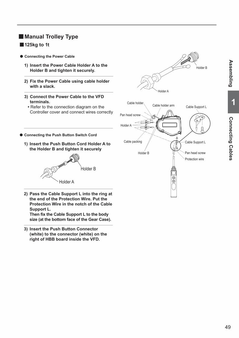
49
■Manual Trolley Type ■125kg to 1t
Assem
blingC
onnecting Cables
1
2) Fix the Power Cable using cable holder with a slack.
3) Connect the Power Cable to the VFD terminals.
• Refer to the connection diagram on the Controller cover and connect wires correctly
1) Insert the Power Cable Holder A to the Holder B and tighten it securely.
● Connecting the Power Cable
● Connecting the Push Button Switch Cord
1) Insert the Push Button Cord Holder A to the Holder B and tighten it securely
2) Pass the Cable Support L into the ring at the end of the Protection Wire. Put the Protection Wire in the notch of the Cable Support L.
Then fix the Cable Support L to the body size (at the bottom face of the Gear Case).
3) Insert the Push Button Connector (white) to the connector (white) on the right of HBB board inside the VFD.
Holder A
Holder B
Cable holder Cable holder arm
Holder A
Cable Support L
Pan head screw
Pan head screw
Protection wire
Cable packing
Holder B
Cable Support L
Holder A
Holder B

50
1
Inst
alla
tion
Con
nect
ing
Pow
er a
nd P
ower
Cab
les
/ Ins
talli
ng th
e Su
spen
ded
Type
(hoi
st o
nly)
Installation
■Installing the Suspended Type (hoist only) ■Checking Installation Method and Place
CAUTION • Connect the Power Cable to the power of rated voltage.
Failure to comply with this instruction causes bodily injury or loss of property.
Mandatory
• Do not install the electric chain hoist at a place exposed to rain or water always or the place different from the Operational Environment (P17).
• Do not install the electric chain hoist in the motion space of other trolley or any other moving equipment (facility). • Do not use the electric chain hoist contacting with other object, or being fixed.
Failure to comply with these instructions may result in death or serious injury.
• Installation (removal) of the electric chain hoist must be carried out by special installer or by personnel with expertise.Consult with the sales shop or KITO for installation, or consign the installation work to special installer or personnel with expertise.
• When installing or removing the electric chain hoist, follow the instructions in Owner's Manual. • Carry out the work for grounding (earthing) and installation of earth leakage
breaker.These work must be carried out by an electric work specialist.
• When the installation is completed, carry out “Check after Installation". (See P54) • Connect the power after all installation works have been completed and just
before the oparation check. • Mount the stopper at the both ends of the travel rail for trolley. <Fig. A> • Make sure that the strength of the structure is sufficient to install the electric chain hoist. • Carry out the installation work after securing the stable hoothold. • Before building the electric chain host into part of your own travel device without using the standard trolley,
contact us for information on precautions.
Failure to comply with these instructions may result in death or serious injury.
Mandatory
Prohibited
A
• When using an electric chain hoist suspended (as a single unit), make sure that the Suspension Eye is installed and hooked securely.
• Install the electric chain hoist so that the Suspension Eye itself can swing freely. (Make sure not to restrain the Suspension Eye when in use.)
• Do not install and use the electric chain hoist upside down. • The diameter of the Suspension Shaft hooked by Suspension Eye should be thinner than 31mm or less.
Refer to the Suspension Eye dimension (P38).
Failure to comply with these instructions may result in death or serious injury.
Mandatory
■Connecting Power and Power CableWhen connecting the Power Cable to the power, connect the cable in accordance with the following instructions.
● Connect the electric chain hoist to the power through a breaker. ● Connect the electric chain hoist in the correct phase. ● Earth wire is a green colored covered cable with yellow line. Carry out Class D earthing work.
● Use correct breaker and Power Cable referring to Checking Power and Power Cable (P45, 46) for the breaker capacity, Power Cable length and its size.
DANGER
DANGER
Stopper
Travel rail
Trolley
L1R-
phase
Red
White
Black
Red
White
Black
Green/Yellow
L2S-
phas
L3T-
phaseBreaker
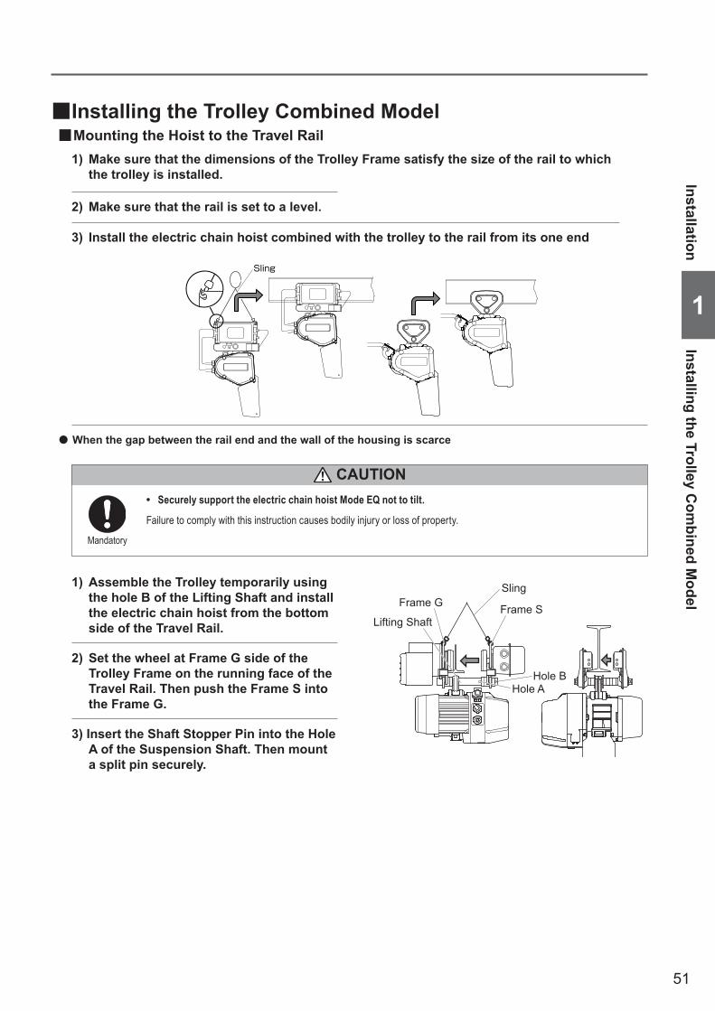
51
InstallationInstalling the Trolley C
ombined M
odel
1
■Installing the Trolley Combined Model ■Mounting the Hoist to the Travel Rail
Sling
3) Install the electric chain hoist combined with the trolley to the rail from its one end
2) Set the wheel at Frame G side of the Trolley Frame on the running face of the Travel Rail. Then push the Frame S into the Frame G.
1) Assemble the Trolley temporarily using the hole B of the Lifting Shaft and install the electric chain hoist from the bottom side of the Travel Rail.
● When the gap between the rail end and the wall of the housing is scarce
3) Insert the Shaft Stopper Pin into the Hole A of the Suspension Shaft. Then mount a split pin securely.
• Securely support the electric chain hoist Mode EQ not to tilt.
Failure to comply with this instruction causes bodily injury or loss of property.
Mandatory
CAUTION
1) Make sure that the dimensions of the Trolley Frame satisfy the size of the rail to which the trolley is installed.
2) Make sure that the rail is set to a level.
Hole B
Frame G Frame S
Sling
Hole A
Lifting Shaft

52
1
Inst
alla
tion
Inst
allin
g th
e Tr
olle
y C
ombi
ned
Mod
el
Capacity ~1tBeam width 100 125 150 175
Material dimensions L-50x50x6 L-50x50x6 L-65x65x8 L-75x75x9
H 80 80 80 80E 50 50 65 75F 40 50 65 75G 50 50 50 50C 30 30 35 40K 65 t2+50 t2+50 t2+50d 14 14 14 14
Bolt size M12x50x50 M12x55x55 M12x55x55 M12x60x60
■Mounting the StopperBe sure to mount the stoppers at the both ends of the rail to prevent drop.Decide the mounting position in accordance to the size of the wheel.When the customer wants to make the stopper by oneself, refer to the following figures.
F
H
Beam widtht2
BoltG
K
C
E
Stopper
Nuts (double nuts)
d
● When using T-shape SuspenderInstall the additional stopper for T-shape Suspender at the end of one rail.
(Unit: mm)
NOTE) Dimension K is for the case to use combining the hoist with the motorized trolley. When using the hoist combined with a manual trolley, mount the stopper in accordance with the bumper position.
(to be continued)
Installation (continued)Chapter 1 Handling the Product
Power Cable
T-shape Suspender
Stopper for T-shape Suspender
Stopper for Trolley
Power CableT-shape Suspender
Stopper for T-shape Suspender
Stopper for Trolley

53
InstallationInstalling the Trolley C
ombined M
odel
1
Messenger WireConnection Box
Cable hanger
Power Cable
Wire Guide
Pan head screw
Messenger Wire
Wire support bar
Rail
Wire support bar
Beam Connection Box
Cable support arm
MotorA
A
Cable Hanger
Wire bolt
■Power Cable Layout for Motorized/Manual trolley type• In the standard specification the Suspender is provided. T-shape Suspender and angle type Suspender are also
available as optional parts. T-shape Suspender can be applicable to curved rail, however, the application method differs depending on the condition such as radius of curvature. In such case, contact KITO.
2) Tie the Messenger Wire passed through the Cable Hanger to the Wire Support Bar with two Wire Bolts.
• The recommended mounting interval of the Cable Hangers is 1.5 m to 2 m.
• Use steel wire of 3 to 6 mm in diameter for the Messenger Wire.
1) Mount the wire support bar at the both ends of the rail.
3) Loosen two pan head screws and remove the end clip of the wire guide.
4) Pass the Messenger Wire through the groove of the messenger guide. Mount the end clip with two pan head screws.
• The dimension A between the side face of the rail and the groove of the wire guide must be same as that of mounting hole of the Wire support bar for the Messenger Wire and the side face of the rail.
5) Fix the Power Cable to the Cable Hanger.
6) Mount the Cable Support to the Cable Support Arm.
7) Insert the Power Cable into the Connection Box of MR2Q and connect it to the terminal panel.
• Connect wires correctly according to the wiring diagram affixed on the Connection Box.

54
1
Che
ck a
fter I
nsta
llatio
n
Check after Installation
■Check itemsMake sure that the following are satisfied:• No bolt, nut nor split pin is lost. Tightening and assembling are completed.• Protection Wire for Push Button Switch Cord is securely tied to accept and endure the force instead of Push
Button Switch Cord when the Push Button Switch Set is drawn.• The Power Cable is fixed to the Cable Support.• Source voltage is the rated voltage• Grounding Wire (earth wire) is connected securely.
● When using with a TrolleyCheck the following:• The electric chain hoist and the trolley are combined correctly.• The stoppers for trolley are securely mounted to Travel Rail where the Trolley travels.• The surface of Travel Rail is not attached with paint or oil. (The surface of the Travel Rail must be basis metal. Do
not paint.) There is no obstacle for the trolley to travel. The Travel Rail is set to a level.
■Operational CheckCarry out the operational check in accordance with Daily inspection (P19).
Wrong assembling or installation causes death or serious injury. To prevent such danger check the following.

55
Chapter 2Inspection
This chapter describes frequent inspection items and periodic inspection items. Refer to Chapter 1 for the “Handling the Product”. Inspection is the first step of safety. Carry out daily inspection, frequent inspection and periodic check.
Table of Contents ................................................................................56

56
■ Periodic Inspection(Carry out the periodic inspection after check of no abnormality in daily inspection and frequent inspection items.)
■Electric Chain Hoist (EQ) Periodic InspectionSuspension Eye, Bottom Hook
Number of start …………………………………… 68
Peripheral parts of the Body sizeChain Guide ……………………………………… 68Chain Spring ……………………………………… 69Stopper …………………………………………… 69Limit Switch Cover ……………………………… 69
OilOil Leakage ……………………………………… 70Oil amount and stain …………………………… 70
Electromagnetic BrakeBrake ……………………………………………… 71
Driving MechanismBearing …………………………………………… 72Load Gear, Gear 2, Gear 3, Motor Shaft …………… 72Friction Clutch …………………………………… 72Abrasion and flaw of the Load Sheave ………… 73
Electrical EquipmentElectrical Parts …………………………………… 74Wiring ……………………………………………… 74Contamination and attachment of foreign matter … 74VFD ………………………………………………… 74
Electric Characteristics MeasurementSource Voltage …………………………………… 74Insulation Resistance …………………………… 74Grounding Resistance …………………………… 75
Function and PerformanceOperational Check ……………………………… 75Brake ……………………………………………… 75
■ Safety Precautions ………………………………… 58 ■Frequent Inspection
(Carry out the frequent inspection after check of no abnormality in daily inspection items.)
■Electric Chain Hoist (EQ) Frequent InspectionLoad Chain
Elongation of Pitch ……………………………… 61Abrasion of wire diameter ……………………… 61
Suspension Eye, Bottom Hook
Opening and Abrasion of the Hook, Abrasion of the Suspension eye ……………………………… 62
Deformation, Flaw, Corrosion ………………… 62
Peripheral parts of the Body sizeChain Container ………………………………… 63
Electromagnetic BrakeNumber of start …………………………………… 63
Push Button SwitchPush Button Switch Body size ………………… 64Push Button Switch Cord ……………………… 64
Power SupplyPower Cable ……………………………………… 65Cable Hanger …………………………………… 65Messenger Wire ………………………………… 65
Function and PerformanceAbnormal Noise ………………………………… 65
■Motorized Trolley (MR2Q) Frequent InspectionAppearance
Travel Rail ………………………………………… 66Oiling (to the gears of wheel) …………………… 66
Push Button Switch, Power Supply …………… 66(Refer to Electric Chain Hoist (EQ) Frequent Inspection)
■ Manual Trolley (TS2) Frequent InspectionAppearance
Combination ……………………………………… 66Travel Rail ………………………………………… 66Oiling (to the gears of wheel) …………………… 66
Table of Contents
Tabl
e of
Con
tent
s
2
Chapter 2 Inspection
57
Table of Contents
2
■Motorized Trolley (MR2Q) Periodic InspectionBrake
Appearance ……………………………………… 76Abrasion of Brake Pad …………………………… 76
Body size ComponentsWheel ……………………………………………… 76Side Roller ………………………………………… 76Lifting Shaft ……………………………………… 77Gear Frame Packing …………………………… 77Gears and Motor Shaft ………………………… 77Suspension Eye ………………………………… 77
Travel RailRail Surface ……………………………………… 78Deformation and Abrasion ……………………… 78Rail Mounting Bolt ……………………………… 78Stopper …………………………………………… 78
Relay CableAppearance ……………………………………… 78
Electrical Equipment and Electric Characteristics … 78
Function and PerformanceOperational Check ……………………………… 79Brake ……………………………………………… 79Abnormal Noise ………………………………… 79
■ Manual Trolley (TSP) Periodic InspectionBody size Components
Wheel ……………………………………………… 80Lifting Shaft ……………………………………… 80Suspension Eye ………………………………… 80
Travel RailRail Surface ……………………………………… 80Deformation and Abrasion ……………………… 81Rail Mounting Bolt ……………………………… 81Stopper …………………………………………… 81
Function and PerformanceOperational Check ……………………………… 81Abnormal Noise ………………………………… 81
■ Guidelines for Parts Replacement based on Indication of CH MeterGuidelines and Precautions on Gear Oil Change Cycle … 82Guidelines for Checking Brake …………………… 82Guidelines on Gear Parts Replacement (Load Gear, Friction clutch with Gear 2, Gear 3) … 83Guidelines on Motor Shaft (with Rotor) Replacement … 83Guidelines on Bearing Replacement …………… 83Guidelines on Hook, Yoke and Suspension Eye Replacement ………………………………………… 83
●ReferenceDaily inspection is described in Chapter 1 “How to Use the Product”. Refer to the following daily inspection items and their relevant pages.
■Daily Inspection of Electric Chain Hoist (EQ)Appearance
Indication of Nameplates and Labels ………… 19Deformation and damage of main unit and each part … 19Loosened or fallen off bolts, nuts and split pins … 19
Load ChainElongation of Pitch ……………………………… 20Abrasion of Wire Diameter …………………… 20Deformation, Flaw, Entanglement …………… 20Rust, Corrosion ………………………………… 20Lubrication ……………………………………… 20Mark ……………………………………………… 20
Suspension Eye / Bottom HookOpening of the Hook …………………………… 21Abrasion ………………………………………… 21Deformation, Flaw, Corrosion ………………… 21Hook Latch ……………………………………… 21Hook movement (Rotation) …………………… 21Bottom Yoke ……………………………………… 22
Peripheral parts of the body sizeBottom Yoke ……………………………………… 22
Push Button SwitchSwitch body size ………………………………… 22
Function and PerformanceOperational Check ……………………………… 23Brake ……………………………………………… 23Limit Switch ……………………………………… 23Check for no Abnormal Sound ………………… 23
Daily Inspection of Motorized Trolley (EQM)Appearance
Indication of Nameplates and Labels ………… 24Deformation and damage of each part ……… 24Loosened or fallen off bolts, nuts and split pins … 24
Function and PerformanceOperational Check ……………………………… 24Brake ……………………………………………… 24
■Daily Inspection of Manual Trolley (EQSP)Appearance
Indication of Nameplates and Labels ………… 25Deformation and damage of each part ……… 25Loosened or fallen off bolts, nuts and split pins … 25
Function and PerformanceOperational Check ……………………………… 25
■ Check of Operating Hours and Number of Start (CH Meter)Start Times/Operating Hour Display Device ................ 84The display contents of the number of start and operating hours ..... 84Displaying of the numbers of start and operating hours .....84Calculating the number of start .............................. 85Converting the operating hours ............................. 85

58
Safety PrecautionsChapter 2 Inspection
• Do not use the part exceeding the service limit or criteria and the parts other than genuine part for KITO electric chain hoist.Even if the part is genuine KITO part, it cannot be used for other model. Refer to Disassembly/Assembly Manual (Annex) for the correct use of the part.
• Do not adjust or disassemble the Brake or Friction Clutch. • Do not adjust the set nut. • Do not carry out the inspection of electric chain hoist with a lifted load. • Do not use the electric chain hoist removing the chain spring and the stopper. • Turn off the main power when carrying out the inspection.
Failure to comply with these instructions may result in death or serious injury.
Prohibited
Mandatory
• Be sure to carry out the frequent and periodic inspection. • Periodic inspaction of the electric chain block must be performed by maintenance engineer. • When oiling the Friction Clutch, use KITO genuine oil (manufacturer specified oil). • When using oils such as gear oil and grease, avoid places with fire or sparks. • Put the electric chain hoist on the floor or work bench when performing the repair and disassembling of the
electric chain hoist. • Even if each component of the electric chain hoist does not exceed the service limit, replace the part
exceeding the total operating hours derived from the grade indicated on the electric chain hoist and the load factor.
• Do not use the electric chain hoist when any abnormality was observed during the inspection. Indicate “FAILURE” on the hoist and contact with maintenance engineer or KITO for repair.
• After completion of the inspection (frequent, periodic), perform the functional check and make sure that the electric chain hoist operates correctly.
• When performing the functional check, be sure to perform the capacity test after no load test.
Failure to comply with these instructions may result in death or serious injury.
CAUTION • Indicate “CHECKING” when performing the inspection.
When a crane is operated erroneously during the inspection, it may result in the accident such as fall-off of parts and tools and downfall.
• Wear protection equipment such as protection goggles and gloves depending on the work contents.Otherwise it may result in the injury due to scattered oil or sharp edge of a part.
• Pay attention to work method, work procedure and work posture.If the product or the part is heavy, your hand is caught or your waist is hurt.Especially be careful for the work on an unstable scaffold such as the work at high lifted place using stepladder.
• Wear helmet and safety belt when carrying the high lift work.Otherwise it may result in injury or downfall accident.
• Remove the oil attached to the product or spilt on the floor.Otherwise it may result in injury due to drop of the product or overturning.
• Keep the work area clean when disassembling the product.Assembling or mixing the part other than genuine part may result in the damage of the product or the accident due to defective operation.
Mandatory
■General Matters related to Inspection
Gen
eral
Mat
ters
rela
ted
to In
spec
tion
Safe
ty P
reca
utio
ns
2
DANGER

59
Safety Precautions
2
General M
atters related to Inspection
NOTE • When performing the frequent inspection, carry out the daily inspection at the same time. • When performing the periodic inspection, carry out the frequent inspection and the daily inspection at the same time. • When detecting any abnormality during inspection due to erroneous use, instruct the operator and user for correct use of
the electric chain hoist.Ex. (1) The flaw on the Chain Guide hit with the Chain (Cause: lifting incline)
(2) The deformation of the Chain Spring (Cause: excessive use of the limit switch)
60
● Check the electric chain hoist as installed, standing on the floor.
Frequent Inspection
• After completion of the frequent inspection, perform the functional check and make sure that the electric chain hoist operates correctly.
Neglecting to perform the functional check may result in death or serious injury.
• USE KITO genuine VFD.The VFD requires the special specification for KITO. Be sure to use genuine VFD.
Failure to comply with this instruction may result in death or serious injury.
Mandatory
NOTEWhen performing the frequent inspection, carry out the daily inspection at the same time.
Chapter 2 Inspection
■General Matters on Frequent Inspection
■General Matters on Handling the Model EQ Electric Chain HoistThe Model EQ Electric Chain Hoist is controlled by the VFD for important items related to safety such as operation, braking and emergency stop. Be sure to follow the safety precautions below as well as the above safety precautions.
• Do not disassemble the Model EQ Electric Chain Hoist in the same way as the contactor system. • Do not change the VFD parameter.
When parameters need to be changed, ask our distributors nearest to the customer or KITO.
• Do not carry out the work such as maintenance and inspection within 5 minutes after power off.Wait for the completion of discharging of the capacitor inside the VFD.
• USE KITO genuine VFD.The VFD requires the special specification for KITO. Be sure to use genuine VFD.
• Do not change the connection of the VFD.When the wires were removed for any reason, connect them again correctly checking the wiring diagram inside the controller cover.
• Do not carry out withstand voltage test of a circuit while the VFD is connected. • Do not turn off the power while operating.
Failure to comply with these instructions may result in death or serious injury and the damage of VFD.
Prohibited
Gene
ral M
atter
s on F
requ
ent In
spec
tion /
Gen
eral
Matte
rs on
Han
dling
the M
odel
EQ E
lectri
c Cha
in Ho
istFr
eque
nt In
spec
tion
2
DANGER
DANGER
Mandatory

61
Item Check method Criteria When failed
Elongation of Pitch
• Measure the elongation of pitch with point caliper. (Measure the sum of pitches of 5 links)
Check the engaging point of the Load Sheave especially carefully.
NOTE
• The limit value of the following “Sum of pitches offivelinks”mustnotbeexceeded.
Replace the Load Chain.
Abrasion of wire diameter
• Measure the wire diameter (d) with point caliper.
d
• The limit value of the following “Wire diameter oftheLoadChain”mustnotbeexceeded.
When the abrasion of the Load Chain is observed, be sure to check the abrasion of the Load Sheave also. (Refer to “Periodic Inspection”, “Load Sheave” (P73).)
NOTE
Replace the Load Chain.
Sum of pitches of 5 links
■Electric Chain Hoist (EQ) Frequent Inspection ■Load Chain ● Check the Load Chain after removing the stain on the chain. ● Use the needle head caliper (point caliper) to measure the sum of pitches and wire diameter. ● Apply oil on the Load Chain after inspection. ● Application of lubricant influences on the life of the Load Chain considerably. Use the KITO genuine lubricant or equivalent (industrial lithium grease: consistency No.0)
● Release all loads from the Load Chain. Apply the lubricant to the linking portion of the Load Chain that engages the Load Sheave and the linking portion of the Load Chain.
● After applicationof the lubricant, lift/lower the electric chain hoist without load to spread the lubricant on the Load Chain.
Load Chain Pitch and Wire Diameter for Each Capacity
Code CapacityLoad Chain
diameter (mm)
Sum of 5 Links (mm) Load Chain diameter (mm)Do not exceed the limit Do not fall under the limit
Standard Limit Standard Limit
EQ001IS 125kg
5.6 79 81.5 5.6 5.1EQ003IS 250kg
EQ005IS 500kg
EQ010IS 1t 7.1 100 103 7.1 6.4
Frequent Inspection
2
Electric Chain H
oist (EQ) Frequent Inspection
(to be continued)

62
Item Check method Criteria When failed
Opening and Abrasion of the HookAbrasion of the Suspension eye
• Check visually and measure with vernier caliper.
b
c
a
Embossed mark • Compare the dimensions of a, b
and c with those at purchasing. Check that they are within the criteria.
The use of the Hooks with these dimensions exceeding the criteria may result in bodily injury or property damage.
Mandatory
CAUTION
Measured value (mm) Limit value
Bottom HookDimension a Not to exceed the dimension at purchasingDimension b
Abrasion not to exceed 5%Dimension c
Suspension EyeDimension dDimension e
• Following tables shows the nominal standard values. Please be aware that these values include tolerance because of forging.
Guidelines on the Hook and Suspension Eye (refer to P83) or its criteria
Replace the Hook and Suspension eye.
Deformation, Flaw, Corrosion
• Check visually. • No deformation such as bend or twist• No deep cut• No loosened bolt or not, or their fall off• No considerable corrosion• No attachment of foreign matter such as
sputter
Replace the Hook.
Frequent Inspection (continued)Chapter 2 Inspection
■Suspension Eye, Bottom Hook
Elec
tric
Cha
in H
oist
(EQ
) Fre
quen
t Ins
pect
ion
Freq
uent
Insp
ectio
n
2
Code CapacityBottom Hook Suspension Eye
Dimension a (mm) Dimension b (mm) Dimension c (mm) Dimension d (mm) Dimension e (mm)Standard Standard Limit value Standard Limit value Standard Limit value Standard Limit value
EQ001IS 125kg45.0 17.5 16.6 23.5 22.3 8.0 7.6 16.0 15.2EQ003IS 250kg
EQ005IS 500kgEQ0101S 1t 50.0 22.5 21.4 31.0 29.5 12.3 11.7 22.0 20.9
e
d

63
● Use check stand to check the electric chain hoist from the close point.
Item Check method Criteria When failed
Chain Container
• Check visually. • To be mounted to the body size securely• No damage, tear, abrasion or deformation• Check no foreign matter inside the Chain
Container. * Especially be careful when the electric chain
hoist is used outdoor.• Make sure that the lift of the Load Chain
is smaller than the capacity of the Chain Container.
Replace the Chain Container.Discard the foreign matter in the Chain Container.
Replace the Chain Container with the adequate Chain Container referring to “Mounting the Chain Container”(P35).
• Use the Chain Container with the capacity larger than the lift of the Load Chain.
Otherwise it may result in death or serious injury due to drop of the Load Chain.
DANGER
■Peripheral parts of the Body size
Item Check method Criteria When failed
Number of start
• Check the number of start with the CH Meter.
• The number of start must be less than one million times. * Estimate the time to reach at one million
times.
Perform the inspection in accordance with “Displaying the numbers of start and theoperatinghours”(P84).
■Electromagnetic Brake
Frequent Inspection
2
Electric Chain H
oist (EQ) Frequent Inspection
(to be continued)
Prohibited
Mandatory
• Do not use the torn Chain Container.
Otherwise it may result in death or serious injury due to drop of the Load Chain.

64
Frequent Inspection (continued)Chapter 2 Inspection
Item Check method Criteria When failed
Push Button Switch Body size
• Check visually and by operation.
• No damage, deformation and loosened bolt.• Push Button Switches can be operated
smoothly.• Emergency Stop Button can be operated and
cancelled.
Replace the Push Button Switch.
Push Button Switch Cord
• Check visually. • Push Button Switch Cord is securely connected.
• The Protection Wire is tied with the body size so that Push Button Switch Cord is not strained directly even if the Push Button Switch is pulled.
Tie the Push Button Switch Cord and the Protection Wire to the body size properly.
• To have no damage Replace the Push Button Switch Cord.
■Push Button Switch
Elec
tric
Cha
in H
oist
(EQ
) Fre
quen
t Ins
pect
ion
Freq
uent
Insp
ectio
n
2
Push Button Switch Cord
Body
Protection Wire
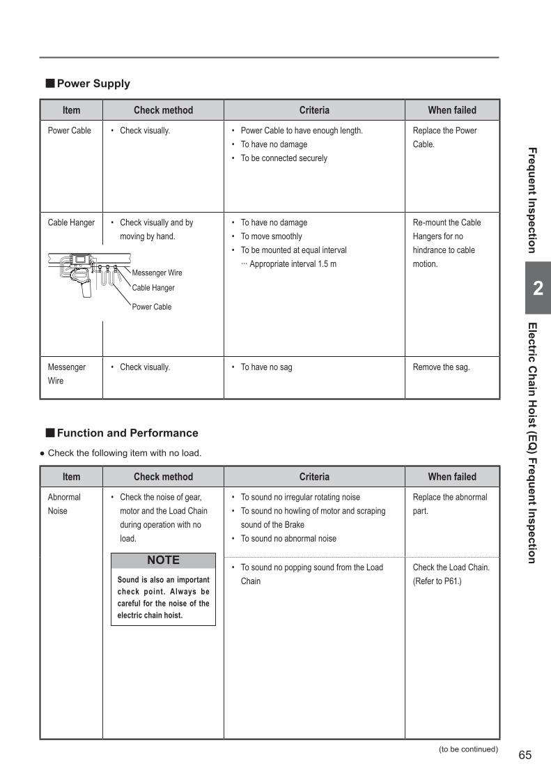
65
Item Check method Criteria When failed
Power Cable • Check visually. • Power Cable to have enough length.• To have no damage• To be connected securely
Replace the Power Cable.
Cable Hanger • Check visually and by moving by hand.
• To have no damage• To move smoothly• To be mounted at equal interval
··· Appropriate interval 1.5 m
Re-mount the Cable Hangers for no hindrance to cable motion.
Messenger Wire
• Check visually. • To have no sag Remove the sag.
■Power Supply
Item Check method Criteria When failed
Abnormal Noise
• Check the noise of gear, motor and the Load Chain during operation with no load.
Sound is also an important check point . Always be careful for the noise of the electric chain hoist.
NOTE
• To sound no irregular rotating noise• To sound no howling of motor and scraping
sound of the Brake• To sound no abnormal noise
Replace the abnormal part.
• To sound no popping sound from the Load Chain
Check the Load Chain. (Refer to P61.)
● Check the following item with no load.
■Function and Performance
(to be continued)
Frequent Inspection
2
Electric Chain H
oist (EQ) Frequent Inspection
Messenger Wire
Power Cable
Cable Hanger

66
Frequent Inspection (continued)Chapter 2 Inspection
■Manual Trolley (TS2) Frequent Inspection ■Appearance
Item Check method Criteria When failed
Travel Rail • Check visually. • To have no considerable deformation and damage
Check items in accordance with “TravelRail”describedin Chapter 2 “Periodic Inspection”.(P78)
Oiling (to the gears of wheel)
• Check visually. • To be oiled adequately Apply oil to gears.
■Motorized Trolley (MR2Q) Frequent Inspection ■Appearance
Item Check method Criteria When failed
Combination • Shake the manual trolley to check.
• The motorized trolley shakes lightly to right and left.
Combine the electric chain hoist and the manual trolley securely.
Travel Rail • Check visually. • To have no considerable deformation and damage
Check items in accordance with “TravelRail”describedin Chapter 2 “Periodic Inspection”.(P78)
Oiling (to the gears of wheel)
• Check visually. • To be oiled adequately Apply oil to gears.
■Push Button Switch, Power SupplyCarry out the inspection referring to “Frequent Inspection Items” of the electric chain hoist (EQ). (P64)
Mot
orize
d Tr
olley
(MR2
Q) F
requ
ent I
nspe
ctio
n / M
anua
l Tro
lley (
TS2)
Fre
quen
t Ins
pect
ion
Freq
uent
Insp
ectio
n
2

67
● Disassemble the electric chain hoist and check that it is assembled correctly without abnormal parts.
• Put the electric chain hoist on the floor or work bench when inspecting the electric chain hoist. • After completion of the periodic inspection, perform the functional check and make sure that the electric
chain hoist operates correctly.· Wear insulating gloves when measuring voltage.· When measuring the electric characteristics (insulation resistance, but except voltage measurement), turn off the
power.
Failure to comply above instructions may result in death or serious injury.
Mandatory
NOTEWhen performing the periodic inspection, carry out the daily inspection at the same time.
■General Matters on Handling the Model EQ Electric Chain Hoist
• Do not disassemble the Model EQ Electric Chain Hoist in the same way as the contactor system. • Do not change the VFD parameter.
When parameters need to be changed, ask our distributors nearest to the customer or KITO.
• Do not carry out the work such as maintenance and inspection within 5 minutes after power off.Wait for the completion of discharging of the capacitor inside the VFD.
• USE KITO genuine VFD.The VFD requires the special specification for KITO. Be sure to use genuine VFD.
• Do not change the connection of the VFD.When the wires were removed for any reason, connect them again correctly checking the wiring diagram inside the controller cover.
• Do not carry out withstand voltage test of a circuit while the VFD is connected. • Do not turn off the power while operating.
Failure to comply with these instructions may result in death or serious injury and the damage of VFD.
Prohibited
■General Matters on Periodic Inspection
Periodic Inspection
The Model EQ Electric Chain Hoist is controlled by the VFD for important items related to safety such as operation, braking and emergency stop. Be sure to follow the safety precautions below as well as the above safety precautions.
Periodic Inspection
2
General Matters on Periodic Inspection / General Matters on Handling the Dual Speed VFD Model
(to be continued)
DANGER
DANGER
• USE KITO genuine VFD.The VFD requires the special specification for KITO. Be sure to use genuine VFD.
Failure to comply with this instruction may result in death or serious injury.Mandatory

68
Chapter 2 Inspection
Periodic Inspection (continued)
■Peripheral parts of the Body size
Item Check method Criteria When failed
Number of start
• Check the number of start with the CH Meter.
• Number of start must not exceed the guidelines for replacement.
Replace the Suspension Eye and Bottom Hook.
Item Check method Criteria When failed
Chain Guide
• Check visually. • To have no apparent abrasion, deformation and damage
• TohavenoflawduetohittingbytheLoadChain
• The flaw due to hitting is caused by wrong use such as lifting a load in an inclined direction. If the abrasion is observed on the Chain Guide, the Load Chain may be worn also. Refer to the item of Load Chain Abrasion and check the abrasion.
Neglecting the check of the Load Chain abrasion may result in bodily injury or property damage.
CAUTION
Mandatory
Replace the Chain Guide.
■Electric Chain Hoist (EQ) Periodic Inspection ■Suspension Eye, Bottom Hook
Elec
tric
Cha
in H
oist
(EQ
) Per
iodi
c In
spec
tion
Perio
dic
Insp
ectio
n
2
Chain Guide

69
Item Check method Criteria When failed
Chain Spring • Check visually and measure the dimensions.
Dimensional standard
• Check visually to have no apparent setting (deformation).
• The deformation of the Chain Spring is caused by excessive use of the Friction Clutch and the Limit Switch. Operate the electric chain hoist properly.
Otherwise it may result in bodily injury or property damage.
CAUTION
Mandatory
Service Limit of Chain Spring for Capacity (Do not fall short of the limit value.)
Code Capacity
Length of Chain Spring(mm)
Standard Limit value
EQ005IS 500kg 29 26.5
EQ010IS 1t 26.5 24
Replace the Chain Spring.
Stopper • Check visually. • The stopper must be attached securely at the third link from the no load end of the Load Chain.
Attach the Stopper at the third link.
Limit Switch Cover
• Check visually. • To have no deformation, damage and abrasion• To have no stain
Replace the Limit Switch Cover.Disassemble the Limit Switch Cover and clean it.
Periodic Inspection
2
Electric Chain H
oist (EQ) Periodic Inspection
(to be continued)
Stopper
Limit Switch Cover
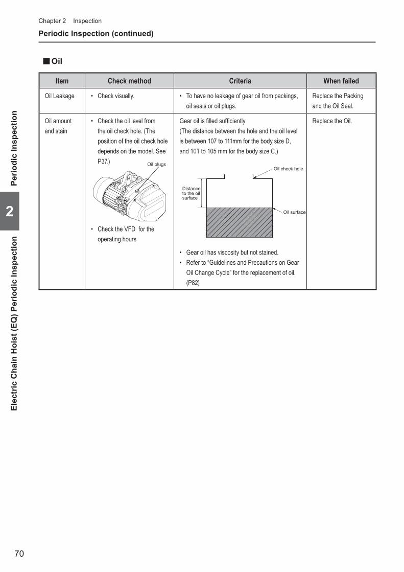
70
Chapter 2 Inspection
Periodic Inspection (continued)
Item Check method Criteria When failed
Oil Leakage • Check visually. • To have no leakage of gear oil from packings, oil seals or oil plugs.
Replace the Packing and the Oil Seal.
Oil amount and stain
• Check the oil level from the oil check hole. (The position of the oil check hole depends on the model. See P37.)
• Check the VFD for the operating hours
Gearoilisfilledsufficiently(The distance between the hole and the oil level is between 107 to 111mm for the body size D, and 101 to 105 mm for the body size C.)
Distance to the oil surface
Oil check hole
Oil surface
• Gear oil has viscosity but not stained.• Refer to “Guidelines and Precautions on Gear
OilChangeCycle”forthereplacementofoil.(P82)
Replace the Oil.
■Oil
Elec
tric
Cha
in H
oist
(EQ
) Per
iodi
c In
spec
tion
Perio
dic
Insp
ectio
n
2
Oil plugs

71
■Electromagnetic Brake
Periodic Inspection
2
Electric Chain H
oist (EQ) Periodic Inspection
(to be continued)
Item Check method Criteria When failed
Brake • Lift and lower the electric chain hoist for 20 to 30 cm with a capacity and then stop it.
• When stopping the operation, the Brake must be applied immediately and the motor must stop.
• Elevating : Stop distance must be 1 % or less of the lifting distance.
Disassemble the Brake to check whether the brake is assembled correctly without abnormal part.
Within 1% of Lifting distance
2~3 Link

72
Periodic Inspection (continued)Chapter 2 Inspection
Item Check method Criteria When failed
Bearing • Check for any strange noises.
• Check the operating hours with the CH Meter.
(Refer to P84.)
• Sounds no strange noise during lifting/lowering operation with no load.
• The operating hours must not exceed the guidelines for replacement. (Refer to Guidelines on Bearing Replacement (P83).)
Replace the Bearing.
Load Gear, Gear 2, Gear 3, Motor Shaft
• Check for any strange noises.
• Check the operating hours using the CH Meter.
(Refer to P84.)
• To have no apparent abrasion• To have no damage• Operating hours not to exceed the guidelines
for replacement (Refer to “Guidelines on Gear Parts Replacement”(P83).)
• Replace the Gear.• Replace the Motor
Shaft.• Replace the oil at
the same time.
Friction Clutch
• Check for any strange noises.
• Check the operating hours using the CH Meter.
(Refer to P84.)
• Sounds no strange noise during lifting/lowering operation with no load.
• Do not adjust or disassemble the Friction Clutch.
Adjusting and disassembling the Friction Clutch may result in death or serious injury.
Prohibited
DANGER
• Operating hours not to exceed the guidelines for replacement (Refer to “Guidelines on Gear Parts Replacement”(P83).)
Replace the Friction Clutch.
■Driving Mechanism
Elec
tric
Cha
in H
oist
(EQ
) Per
iodi
c In
spec
tion
Perio
dic
Insp
ectio
n
2
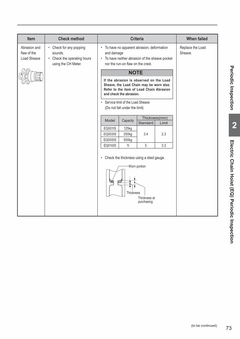
73
Item Check method Criteria When failed
Abrasion and flaw of the Load Sheave
• Check for any popping sounds.
• Check the operating hours using the CH Meter.
• To have no apparent abrasion, deformation and damage
• To have neither abrasion of the sheave pocket northerun-onflawonthecrest.
If the abrasion is observed on the Load Sheave, the Load Chain may be worn also. Refer to the item of Load Chain Abrasion and check the abrasion.
NOTE
• Service limit of the Load Sheave (Do not fall under the limit)
• Check the thickness using a slied gauge.
Replace the Load Sheave.
Periodic Inspection
2
Electric Chain H
oist (EQ) Periodic Inspection
(to be continued)
Model Capacity Thickness(mm)
Standard LimitEQ001IS 125kg
3.4 2.3EQ003IS 250kgEQ005IS 500kgEQ010IS 1t 5 3.3
Worn portion
Thickness at purchasing
Thickness

74
Periodic Inspection (continued)Chapter 2 Inspection
Item Check method Criteria When failed
Electrical Parts
• Remove the Controller Cover and check the electrical parts visually.
• Check the number of start with the CH Meter.
(Refer to P84.)
• To have no damaged or burnt part.• To have no loosened bolt. Electrical parts
must be mounted securely.
Replace the damaged or burnt electrical part.Mount the electrical part securely.
Wiring • WiringmustbefixedtotheElectricalPartssecurely.
• Connectors must be inserted securely.
Connect wirings securely.
• To have no wire breakage and burning Replace the wiring with new wiring, referring to Chapter 3 Guidance on Troubleshooting. (P88 to 89)
Contamination and attachment of foreign matter
• To have not waterdrop or foreign matter. Remove the foreign matter.
VFD • Check the parts with service life (see VFD Manual.) * Contact KITO for the manual
• Electrolytic capacitor: 3000 hours (depending on the use)
Replace the VFD.
■Electrical Equipment
Item Check method Criteria When failed
Source Voltage
• Measure the voltage with a circuit tester.
• The source voltage of the rated voltage ± 10 % at the receiving terminal must be supplied when operating with the capacity.
• Be careful of electric shock when measuring the voltage.
Electric shock may result in death or serious injury.Mandatory
DANGER
Supply proper voltage.
Insulation Resistance
• Measure the insulation resistance with megger. (Resistance between energized and non-energized parts ··· Each phase of R(L1), S(L2) and T(L3) and the earth wire)
• Insulationresistancemustbe5MΩorhigher.
• Turn off the power when measuring the insulation resistance.
Measuring the insulation resistance without turning off the power may result in death or serious injury.
Mandatory
DANGERReplace the Body size.
■Electric Characteristics Measurement
Elec
tric
Cha
in H
oist
(EQ
) Per
iodi
c In
spec
tion
Perio
dic
Insp
ectio
n
2

75
Item Check method Criteria When failed
Operational Check
• Perform the daily inspection items with capacity. (Refer to Daily inspection Items. (P19))
• Be sure to perform the capacity test after completion of the no-load test.
Performing the capacity test without prior no-load test may result in death or serious injury.
Mandatory
DANGER Disassemble the electric chain hoist to check whether it is assembled correctly and has no abnormal part.
• Referto“DailyinspectionItems”.(P19)
Brake • Operate the electric chain hoist with a capacity and then stop it.
• When stopping the operation, the Brake must be applied immediately and the motor must stop.
Up/Down: Stop distance must be 1 % or less of the traveling distance for one minute.
Disassemble the Brake to check whether it is assembled correctly and has no abnormal part.
• After completion of the inspection of each part, perform the operational check for correct operation.
Neglecting to perform the operational check may result in death or serious injury.
Item Check method Criteria When failed
Grounding Resistance
• Measure the grounding resistance with earth-resistance meter.
• Groundingresistance100Ωorless
• Turn off the power when measuring the grounding resistance.
Measuring the grounding resistance without turning off the power may result in death or serious injury due to electric shock.
Mandatory
DANGERMake a grounding correctly.
■Function and Performance
Mandatory
● Perform the following inspections with capacity.
Periodic Inspection
2
Electric Chain H
oist (EQ) Periodic Inspection
(to be continued)
DANGER

76
Periodic Inspection (continued)Chapter 2 Inspection
Item Check method Criteria When failed
Wheel • Check visually.• Measure dimensions D and
d with vernier caliper.
d D
D
Wheel for I · H beam (125kg to 1t)Wheel for I · H beam (125kg to 1t)
XXXXXXXXXXXXXXXXXXXXMeasure the outer diameter with vernier caliper.
• To have no considerable deformation and damage
• Abrasion Limit of Wheel (Do not fall under the limit.)
Capacity Beam typeD (mm) d (mm)
Standard Limit Standard Limit125kg250kg500kg
1t
I · H 95 91 91.5 87.5
Replace the Wheel.
Side Roller • Check visually.• Measure outer diameter of
the worn part with vernier caliper.
Outer diameter
• To have no considerable deformation and damage• Abrasion Limit of Side Roller
(Do not fall under the limit.)
Capacity Sise B(mm)
Standard Limit125kg250kg500kg
1t
38 37
Replace the Side Roller.
■Motorized Trolley (MR2Q) Periodic Inspection ■Brake
Item Check method Criteria When failed
Appearance • Disassemble the Brake and check it visually.
• Tohavenodeformation,flawanddamageonthe Brake Drum and the Motor Cover.
Replace the Part.
• To have no deformation and damage on the Brake Spring.
Replace the Brake Spring.
Abrasion of Brake Pad
• Disassemble the Brake and measure the abrasion.
Trolley Brake Service Limit (Do not fall under the limit.)
Capacity Speed Sise B(mm)Standard Limit
125kg250kg500kg
1t
Dual 32.5 31.0
Replace the Motor Cover.
Brake Pad
Motor Cover
Brake Drum B
■Body size Components
Mot
oriz
ed T
rolle
y (M
R2Q
) Per
iodi
c In
spec
tion
Perio
dic
Insp
ectio
n
2

77
Item Check method Criteria When failed
Lifting Shaft • Check visually.• Measure the shaft diameter
with vernier caliper.
Shaft diameter
• To have no considerable deformation and abrasion
• The shaft with obvious deformation reaches at the service limit.
• Abrasion limit of the shaft is 5 % of its diameter
Replace the Lifting shaft.
Gear Frame Packing
• Check visually.
Gear Frame Packing
• To have no damage and breakage. Replace the Gear Frame Packing.
Gears and Motor Shaft
• Check for any strange noises. • Sounds no strange noise during lifting/lowering operation with no load.
Replace the Part.
Suspension Eye
• Check visually and measure with vernier caliper.
e
d
Measured value (mm) Limit value
Suspension Eye Dimension d
Abrasion not to exceed 5%Dimension e
• Following tables shows the nominal standard values. Please be aware that these values include tolerance because of forging.
Guidelines on the Suspension Eye (refer to P83) or its criteria
Code CapacitySuspension Eye
Dimension d (mm) Dimension e (mm)Standard Limit value Standard Limit value
EQ001IS 125kg8.0 7.6 16.0 15.2EQ003IS 250kg
EQ005IS 500kgEQ0101S 1t 12.3 11.7 22.0 20.9
• Replace the Suspension Eye.
Periodic Inspection
2
Motorized Trolley (M
R2Q
) Periodic Inspection
(to be continued)

78
Periodic Inspection (continued)Chapter 2 Inspection
Item Check method Criteria When failed
Rail Surface • Check visually. • To have no attachment of paint, oil and foreign matter.
• To have no dust and powder due to abrasion
Clean the Travel Rail.
Deformation and Abrasion
• Check the deformation and abrasion visually and measure them with vernier caliper.
I-beam H-beam
B B
tt
• Tohavenodeformationofbeamflangesuchas twist and shear drop
• To have no exceeding abrasion of rail surface• Service limit of B: up to 95 % of the dimension
at purchasing• Service limit of t: up to 90 % of the dimension
at purchasing
Replace or repair the Travel Rail.
Rail Mounting Bolt
• Check visually. • To have no loosened bolt or fall-off Tighten the bolts securely.
Stopper • Check visually.
Stopper Stopper
• The stoppers must be mounted at the both ends of the Travel Rail securely.
Tighten the Stoppers.
■Travel Rail
Item Check method Criteria When failed
Appearance • Check the cable surface visually.
• The Relay Cable has no deformation or damage. To be mounted securely.
Replace the Relay Cable.
■Relay Cable
■Electrical Equipment and Electric CharacteristicsRefer to Electric Chain Hoist (EQ) Periodic Inspection (P74 to 75).
Mot
oriz
ed T
rolle
y (M
R2Q
) Per
iodi
c In
spec
tion
Perio
dic
Insp
ectio
n
2

79
Item Check method Criteria When failed
Operational Check
• Perform the daily inspection items with capacity. (Refer to“DailyinspectionItems”.(P24))
• Be sure to perform the capacity test after completion of the no-load test.
Performing the capacity test without prior no-load test may result in death or serious injury.
Mandatory
DANGER Disassemble the electric chain hoist to check whether it is assembled correctly and has no abnormal part.
• Referto“DailyinspectionItems”.(P24)
Brake • Operate the electric chain hoist with a capacity and then stop it.
• When stopping the operation, the Brake must be applied immediately and the motor must stop. Traveling : Stop distance must be 10 % or less
of the traveling distance for one minute.
(Without swinging of the load. Except the case when the load is swinging.)
Disassemble the Brake to check whether the brake is assembled correctly without abnormal part.
Abnormal Noise
• Operate the electric chain hoist with a capacity and then stop it.
• To have no irrotating noise• To sound no howling of motor and scraping
sound of the Brake.
Disassemble the electric chain hoist to check whether it is assembled correctly and has no abnormal part.
• After completion of the inspection of each part, perform the operational check for correct operation.
Neglecting to perform the operational check may result in death or serious injury.
■Function and Performance
Mandatory
● Perform the following inspections with capacity.
Periodic Inspection
2
Motorized Trolley (M
R2Q
) Periodic Inspection
(to be continued)
DANGER

80
Periodic Inspection (continued)Chapter 2 Inspection
■Manual Trolley (TSP) Periodic Inspection ■Body size Components
Item Check method Criteria When failed
Wheel • Check visually.• Measure dimension D with
vernier caliper. t
d
0.5~3t0.5~3t 5t5t
D D
• Measure the outer diameter with vernier caliper.
• To have no considerable deformation and damage
• Abrasion Limit of Wheel (Do not fall under the limit.)
CapacityBeam
D (mm) Flange thickness (mm)TSP Standard Limit Standard Limit
125kg250kg500kg
H-beam60
58.5
To have no considerable damageorcrackattheflange.
I-beamTo have no considerable damage or crack on the contact suraface.
1tH-beam
7169.5
I-beamTo have no considerable damage or crack on the contact suraface.
Replace the Wheel.
Lifting Shaft • Check visually.• Measure the shaft diameter
with vernier caliper.
Shaft diameter
• To have no considerable deformation and abrasion
• The shaft with obvious deformation reaches at the service limit.
• Abrasion limit of the shaft and the hole is 5 % of its diameter respectively.
Replace the Lifting Shaft.
Suspension Eye
• Check visually and measure with vernier caliper.
e
d
Measured value (mm) Limit value
Suspension Eye Dimension d Abrasion not to exceed 5%Dimension e
• Following tables shows the nominal standard values. Please be aware that these values include tolerance because of forging.
Guidelines on the Hook and Suspension Eye (refer to P83) or its criteria
Code CapacitySuspension Eye
Dimension d (mm) Dimension e (mm)Standard Limit value Standard Limit value
EQ001IS 125kg8.0 7.6 16.0 15.2EQ003IS 250kg
EQ005IS 500kgEQ0101S 1t 12.3 11.7 22.0 20.9
• Replace the Suspension Eye.
Item Check method Criteria When failed
Rail Surface • Check visually. • To have no attachment of paint, oil and foreign matter.
• To have no dust and powder due to abrasion
Clean the Travel Rail.
■Travel Rail
Man
ual T
rolle
y (T
SP) P
erio
dic
Insp
ectio
nPe
riodi
c In
spec
tion
2

81
Item Check method Criteria When failed
Deformation and Abrasion
• Check the deformation and abrasion visually and measure them with vernier caliper.
I-beam H-beam
B B
tt
• Tohavenodeformationofbeamflangesuchas twist and shear drop
• To have no exceeding abrasion of rail surface• Service limit of B: up to 95 % of the dimension
at purchasing• Service limit of t up to 90 % of the dimension
at purchasing
Replace or repair the Travel Rail.
Rail Mounting Bolt
• Check visually. • To have no loosened bolt or fall-off Tighten the bolts securely.
Stopper • Check visually.
Stopper Stopper
• The stoppers must be mounted at the both ends of the Travel Rail securely.
Tighten the Stoppers.
Item Check method Criteria When failed
Operational Check
• Perform the daily inspection items with capacity. (Refer to Daily inspection Items. (P25))
• Be sure to perform the capacity test after completion of the no-load test.
Performing the capacity test without prior no-load test may result in death or serious injury.
Mandatory
DANGER Disassemble the electric chain hoist to check whether it is assembled correctly and has no abnormal part.
• Referto“DailyInspectionItems”.(P25)
Abnormal Noise
• To make the electric chain hoist travel with a capacity
• To have no irregular rotating sound Disassemble the electric chain hoist to check whether it is assembled correctly and has no abnormal part.
■Function and Performance
● Perform the following inspections with capacity.
Periodic Inspection
2
Manual Trolley (TSP) Periodic Inspection
• After completion of the inspection of each part, perform the operational check for correct operation.
Neglecting to perform the operational check may result in death or serious injury.
Mandatory
DANGER

82
When performing the inspection, check the number of start and operating hours and utilize them for operation status control and maintenance control.Check the number of start and operating hours with the indicator of the VFD by the maintenance engineer in accordance with the separate “VFD Manual” and P84 of this manual.
■Guidelines and Precautions on Gear Oil Change CycleChange the gear oil in accordance with the rate of loading and the operating hours.
● Change the oil at every five years even if the operating hours do not reach at the following hours.
Operating hour for gear oil changeRate of loading
Every 120 hrs Every 240 hrs Every 360 hrs
Light A case where the capacity is rarely applied. Usually the hoist is used with a light load. ○
Medium A case where the capacity is applied considerably frequently. Usually the hoist is used with a medium load. ○
Heavy A case where the capacity is applied considerably frequently. Usually the hoist is used with a heavy load. ○
Ultra heavy A case where the capacity is applied constantly. ○
Guidelines for Parts Replacement based on Indication of CH MeterChapter 2 Inspection
Guide
lines
for P
arts R
eplac
emen
t bas
ed on
Indic
ation
of CH
Mete
r
2CAUTION
• Use of wrong gear oil may result in the drop of the lifted load. Be sure to use the designated gear oil.
Mandatory
Code Amount gear oil(ml) OilEQ001IS, EQ003IS, EQ005IS 510 KITO genuine product
EQ010IS 840 KITO genuine product
Gear oil kind and amount for main unit
■Guidelines for Checking Brake ● When the number of start reaches 1 million times, check the dimension of B and execute the counteraction in the table below depending on the condition.
● When the number of start reaches 2 million times, replace the brake drum, motor cover, brake spring and pull rotor spring no matter what condition the B dimension is.
Condition of B dimension ActionWhen it reaches the critical limit Replace the brake drum, motor cover, brake spring and pull rotor spring.When it reaches near end of the critical limit rather than the intermediate point between standard and critical limit.
From that time on, check the B condition every hundred thousand times of use till it reaches to the critical limit.
When it reaches near end of the standard rather than the intermediate point between standard and critical limit. Check the B condition every two hundred thousand times of use.
Abrasion of Brake pad when using Brake
Code Capaciy SpeedB dimension (mm)
CriteriaStandard Critical Limit
EQ001ISEQ003ISEQ005IS
125kg, 250kg, 500kg Dual
3 3.5 Not to exceed
EQ010IS 1t 4 3.5 Not to fall below
B
Brake Pad
Brake Drum
Moter Cover
B
Brake Pad
Brake Drum
Moter Cover
<125kg, 250kg, 500kg> <1t>

83
■Guidelines on Gear Parts Replacement (Load Gear, Friction clutch with Gear 2, Gear 3)
Operating hours to replace partsBody size grade
Every 800 hours Every 1600 hours Every 3200 hours
M5, 2m – Parts replacement –M6, 3m – – Parts replacement
■Guidelines on Motor Shaft (with Rotor) ReplacementOperating hours to replace
Body size grade parts Every 400 hours Every 800 hours Every 1600 hours Every 3200 hours
M5, 2m – Apply grease on spline Parts replacement –M6, 3m – Apply grease on spline – Parts replacement
Guidelines for Parts Replacement based on Indication of CH Meter
2
(to be continued)
* Grease needs to be applied on spline part every 800, 1600 and 2400 hours.
■Guidelines on Bearing ReplacementOperating hours to replace parts
Body size gradeEvery 800 hours Every 1600 hours Every 3200 hours
M5, 2m – Parts replacement –M6, 3m – – Parts replacement
■Guidelines on Hook, Yoke and Suspension Eye ReplacementReplace the Hook, Yoke and Suspension Eye in accordance with the rate of loading and the number of start in the following table.
Number of start to replace partsRate of loading
Every million timesEvery 1.5 million
timesEvery 2 million
times
Light A case where the capacity is rarely applied. Usually the hoist is used with a light load. ○
Medium A case where the capacity is applied considerably frequently. Usually the hoist is used with a medium load. ○
Heavy A case where the capacity is applied considerably frequently. Usually the hoist is used with a heavy load. ○
Ultra heavy A case where the capacity is applied constantly. ○
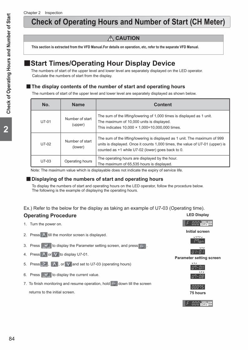
84
Chapter 2 Inspection
Check of Operating Hours and Number of Start (CH Meter)
Chec
k of
Ope
ratin
g Ho
urs
and
Num
ber o
f Sta
rt
2
The numbers of start of the upper level and lower level are separately displayed on the LED operator. Calculate the numbers of start from the display.
■The display contents of the number of start and operating hoursThe numbers of start of the upper level and lower level are separately displayed as shown below.
No. Name Content
U7-01Number of start
(upper)
The sum of the lifting/lowering of 1,000 times is displayed as 1 unit.The maximum of 10,000 units is displayed.This indicates 10,000 × 1,000=10,000,000 times.
U7-02Number of start
(lower)
The sum of the lifting/lowering is displayed as 1 unit. The maximum of 999 units is displayed. Once it counts 1,000 times, the value of U7-01 (upper) is counted as +1 while U7-02 (lower) goes back to 0.
U7-03 Operating hoursThe operating hours are displayed by the hour.The maximum of 65,535 hours is displayed.
■Displaying of the numbers of start and operating hoursTo display the numbers of start and operating hours on the LED operator, follow the procedure below.The following is the example of displaying the operating hours.
Ex.) Refer to the below for the display as taking an example of U7-03 (Operating time).Operating Procedure1. Turn the power on.
2. Press till the monitor screen is displayed.
3. Press to display the Parameter setting screen, and press .
4. Press or to display U7-01.
5. Press , , or and set to U7-03 (operating hours)
6. Press to display the current value.
7. To finish monitoring and resume operation, hold down till the screen
returns to the initial screen.
LED Display
Initial screen
Parameter setting screen
75 hours
Note: The maximum value which is displayable does not indicate the expiry of service life.
CAUTIONThis section is extracted from the VFD Manual.For details on operation, etc, refer to the separate VFD Manual.
■Start Times/Operating Hour Display Device

85
■Calculating the number of startCalculate the numbers of start of the upper level and lower level from the display.
The following is the calculation example.
Example: When “81” is displayed on U7-01 and “567” is displayed on U7-02
The number of start of lowering = 81 × 1,000 + 567 is 81,567 times.
■Converting the operating hoursWhen “122” is displayed on U7-03, the operating hours are 122.
Check of Operating Hours and Num
ber of Start
2

86

87
Chapter 3Troubleshooting
■Guidance on Troubleshooting ........................................................88 ■Safety Precautions ..........................................................................90 ■Troubleshooting...............................................................................91•Power .............................................................................................91•Circuit breaker ..............................................................................91•Power Cable ..................................................................................92•Motor ..............................................................................................93•Brake ..............................................................................................94• Internal wiring ...............................................................................94•Upper/Lower Limit Switch ............................................................95•Push Button Switch ......................................................................96•VFD .................................................................................................97•HBB Board .....................................................................................97•Braking Resistor ...........................................................................97•Electric shock ...............................................................................98•Friction Clutch ..............................................................................98•Hook ...............................................................................................99•Load Chain ..................................................................................101•Load Sheave ................................................................................103•Chain Guide .................................................................................103•Gears ............................................................................................103•Bearing ........................................................................................104•Traveling motion of the Trolley ..................................................104
This chapter describes the main failure cause and inspection items based on the fault conditions. The repair work (and maintenance work as well) of the electric chain hoist is accompanied with disassembling/assembling work. Refer to the separate “Disassembling/Assembling Manual” for the correct work.
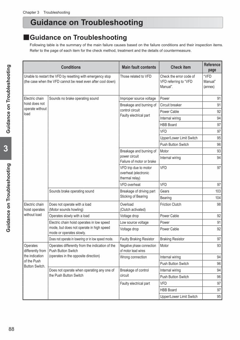
88
Guidance on TroubleshootingChapter 3 Troubleshooting
■Guidance on TroubleshootingFollowing table is the summary of the main failure causes based on the failure conditions and their inspection items. Refer to the page of each item for the check method, treatment and the details of countermeasure.
3
Gui
danc
e on
Tro
uble
shoo
ting
Gui
danc
e on
Tro
uble
shoo
ting Conditions Main fault contents Check item Reference
pageUnable to restart the VFD by resetting with emergency stop (the case when the VFD cannot be reset even after cool down)
Those related to VFD Check the error code of VFD referring to “VFD Manual”.
“VFD Manual” (annex)
Electric chain hoist does not operate without load
Sounds no brake operating sound Improper source voltage Power 91Breakage and burning of control circuitFaulty electrical part
Circuit breaker 91Power Cable 92Internal wiring 94HBB Board 97VFD 97Upper/Lower Limit Switch 95Push Button Switch 96
Breakage and burning of power circuitFailure of motor or brake
Motor 93Internal wiring 94
VFD trip due to motor overheat (electronic thermal relay)
VFD 97
VFD overheat VFD 97Sounds brake operating sound Breakage of driving part
Sticking of BearingGears 103Bearing 104
Electric chain hoist operates without load
Does not operate with a load (Motor sounds howling)
Overload (Clutch activated)
Friction Clutch 98
Operates slowly with a load Voltage drop Power Cable 92Electric chain hoist operates in low speed mode, but does not operate in high speed mode or operates slowly.
Low source voltage Power 91Voltage drop Power Cable 92
Does not operate in lowering or in low speed mode. Faulty Braking Resistor Braking Resistor 97Operates differently from the indication of the Push Button Switch.
Operates differently from the indication of the Push Button Switch (operates in the opposite direction)
Negative phase connection of motor lead wires
Motor 93
Wrong connection Internal wiring 94Push Button Switch 96
Does not operate when operating any one of the Push Button Switch
Breakage of control circuit
Internal wiring 94Push Button Switch 96
Faulty electrical part VFD 97HBB Board 97Upper/Lower Limit Switch 95

89
3
Guidance on Troubleshooting
(to be continued)
Conditions Main fault contents Check item Reference page
Does not stop normally
Too long (or short) stopping distance Abrasion of brake lining Brake 94
Does not stop at the upper/lower limit. Negative phase connection of motor lead wires
Power Cable 92
Wrong connection Internal wiring 94Push Button Switch 96
Abnormal noise
Popping sound Abrasion of the Load ChainAbrasion of the Load Sheave
Load Chain 101Load Sheave 103
Sounds strange operating sound Abrasion or breakage of GearDeterioration of Bearing
Gears 103Bearing 104
Brake noise Sounds when applied (scraping noise)
Dragging Brake 94
Sounds when released Abrasion of brake lining Brake 94Sounds at curved rail (friction noise) Mechanical interference
of the rail and the wheelTraveling motion of the Trolley
104105
Unable to travel
Motorized Trolley/Manual Trolley Slipping wheel Traveling motion of the Trolley
104105Inclined rail
Pulling a load in an inclined direction (floating wheel)Defective gear engagementLocking of brake
Motorized Trolley Electric system failure (refer to the item of electric chain hoist)
Serpentine motionSounds strange noise
Motorized Trolley/Manual Trolley Mechanical interference of the rail and the wheel
Traveling motion of the Trolley
104105
Wrong adjustment of spacerUneven abrasion of the wheelDeformation of the wheelDeterioration of BearingDeformation and abrasion of the railDeterioration of the BearingAbrasion of the Brake Pad
Hook and those related to Hook Deformation Hook 99100
Load Chain and those related to Load Chain Abrasion, elongation, twist Load Chain 101Electric shock when touching the body size and Push Button Switch
Improper grounding, breakage of earth wire
Electric shock 98

90
Safety Precautions
• Do not disassemble or repair the electric chain hoist by the personnel other than maintenance engineer.“Disassembling/Assembling Manual” and “Parts List” are provided separately for the maintenance. Disassembling and repair must be performed by the maintenance engineer in accordance with these materials for maintenance.
Failure to comply with this content may result in death or serious injury.
• USE KITO genuine VFD.The VFD requires the special specification for KITO. Be sure to use genuine VFD.
Failure to comply with this content may result in death or serious injury.
Prohibited
Mandatory
Mandatory
• When replacing the part, be sure to use the genuine part for KITO electric chain hoist EQ, EQM and EQSP.Even if the part is the KITO genuine part, the part for different model may not be used. Use the correct part in accordance with separate “Disassembling/Assembling Manual”.
• When any abnormality is observed during the repair (maintenance) of the electric chain hoist, survey the cause by the maintenance engineer and carry out the repair.
• Be sure to keep the following when repairing the electric chain hoist: • Be sure to turn off the power. • Be sure to indicate “CHECKING”. • Carry out the repair without lifting a load.
• Be sure to pay attention to the change of the operating sound of electric chain hoist and trolley.The change of operating sound is an important factor to judge the failure.
Failure to comply with this content may result in death or serious injury.
Chapter 3 Troubleshooting
■General Matters on Failure Cause and Countermeasure
■General Matters on Handling the Model EQ Electric Chain HoistThe Model EQ Electric Chain Hoist is controlled by the VFD for important items related to safety such as operation, braking and emergency stop. Be sure to follow the safety precautions below as well as the above safety precautions.
• Do not disassemble the Model EQ Electric Chain Hoist in the same way as the contactor system. • Do not change the VFD parameters.
When parameters need to be changed, ask our distributors nearest to the customer or KITO.
• Do not carry out the work such as maintenance and inspection within 5 minutes after power off.Wait for the completion of discharging of the capacitor inside the VFD.
• Fan Cover becomes very hot during operation. Do not touch it. • Do not touch the Fan Cover within 30 minutes after the operation. • USE KITO genuine VFD.
The VFD requires the special specification for KITO. Be sure to use genuine VFD.
• Do not change the connection of the VFD.When the wires were removed for any reason, connect them again correctly checking the wiring diagram inside the controller cover.
• Do not carry out withstand voltage test of a circuit while the VFD is connected. • Do not turn off the power while operating.
Failure to comply with these instructions may result in death or serious injury and the damage of VFD.
Prohibited
3
Gener
al Matt
ers on
Failur
e Caus
e and
Coun
terme
asure
/ Gene
ral Ma
tters
on Ha
ndling
the M
odel E
Q Ele
ctric C
hain H
oist
Safe
ty P
reca
utio
ns
DANGER
DANGER

91
Power
Symptom Cause Remedy Main factor CountermeasureElectric chain hoist does not operate.
Improper source voltage
Measure the voltage of each phase at power receiving terminal.If the source voltage is improper, check the power receiving facility.
Faulty power receiving facility
Check the power receiving facility regularly.
Circuit breaker (Distribution panel)
Symptom Cause Remedy Main factor CountermeasureElectric chain hoist does not operate.
Breaker was tripped due to short circuit.
Replace or repair the short-circuited part. Cable breakage, burning of electrical parts
Refer to each item of Power Cable, Motor and Internal Wiring.
Breaker was tripped due to insufficient breaker capacity.
Check the breaker capacity. Replace it if the capacity is insufficient.
Wrong selection of breaker capacity
Use the breaker with proper capacity. (See P45.)
Breaker was tripped due to over current.
Check the cause of over current and take the necessary countermeasure. (Refer to each item of Power Cable, Motor, Brake and Internal Wiring.)
Over voltage, low voltage, over load
Refer to each item of Power Cable, Motor, and Internal Wiring.
Troubleshooting
• Be careful about electric shock when checking the power.
Careless power check may result in death or serious injury due to electric shock.
3
TroubleshootingPow
er / Circuit breaker (D
istribution panel)
(to be continued)
Mandatory
DANGER

92
Troubleshooting (continued)
Power Cable
Symptom Cause Remedy Main factor CountermeasureElectric chain hoist does not operate.
Wire breakage (more than two wires)
Check the conduction, flaw, crimping of terminals and soldering of plug.When any deficiency was observed, repair or replace the cable.
Excessive force applied on the cable
Support the cable with Cable Support Arm securely.
Non use of shake proof cable
Use shake proof cable to the moving part.
Twist of wire Layout the wires without twisting.
Cable was impeded by other facility.
Fix the cable not to be impeded by other facility.
Wire burning (more than two wires)
Check the cable. Replace it if burnt. Temperature rise due to insufficient cable capacity
Use the cable with proper capacity. (See P45.)
Cables are bundled. Do not bundle wires.
Insufficient insertion of plug
Insert the connector plug to the end of the receptacle. Tighten the coupling ring securely.
Insufficient insertion at the installation
Fix the connector plug to the receptacle securely.
Loosening of the fixing thread due to impact or vibration
Use the electric chain hoist avoiding the large impact.
Slow start or unable to start
Insufficient cable capacity
Check the cable size for adequacy. Replace with the proper cable if the cable capacity is insufficient.
Voltage drop due to insufficient cable capacity
Use the cable with proper capacity. (See P45.)
Electric chain hoist operates but unable to lift a load. (single phase status)
Breakage or burning of one wire only Refer to the breakage and burning of above items.
Chapter 3 Troubleshooting
3
Pow
er C
able
Trou
bles
hoot
ing

93
Motor
Symptom Cause Remedy Main factor CountermeasureMotor does not operate.
Motor coil burning (two or more phases)
Measure the coil resistance of each phase. Replace the motor when the resistance of all phases are infinity.
Over current due to over voltage or low voltage
Operate the electric chain hoist at the rated voltage.
Over current due to over load
Operate the electric chain hoist with a load less than the capacity.
Operation exceeding intermittent rating
Check the intermittent rating. Operate the electric chain hoist within these ratings.
Excessive inching or plugging operation (consecutive impression of start rush current)
Do not perform excessive operation.
Over current due tobrake dragging
Refer to the items of Brake.
Lead wire breakage (more than two lead wires)
Measure the coil resistance of each phase. Replace the motor when the resistance of all phases are infinity.
Lead wire damaged at assembling
Assemble with care.
Vibration, impact Use the electric chain hoist avoiding the impact.
Electric chain hoist operates but unable to lift a load. (single phase status)
Motor coil burning (only one phase)
Measure the coil resistance of each phase. Replace the motor when the resistance of all phases are infinity.
Layer short due to poor insulation of coil (between phases)
Be careful about the intrusion of foreign matter into the motor when assembling.
Lead wire breakage (only in one lead wire)
Measure the coil resistance of each phase. Replace the motor when the resistance of all phases are infinity.
Lead wire damaged at assembling
Be careful not to have the lead wire caught when assembling.
Vibration, impact Use the electric chain hoist avoiding the impact.
3
TroubleshootingM
otor
(to be continued)

94
Troubleshooting (continued)
Brake
Symptom Cause Remedy Main factor CountermeasureStops after traveling over 4 to 5 links after the operation is stopped. (Guideline: The travel of the Load Chain is within 2 to 3 links.)
Abrasion of brake lining
Check the manner of operation (excessive inching or frequent use). Carry out the inspection and use it correctly.
Excessive inching Frequent use
Check the electric chain hoist regularly.Use it correctly in accordance with the manual.
The load slides down when stopped
Defective function of the Friction
Check the place to use and friction function. Carry out the inspection and use it correctly.
Abrasion from habitual use for a long timeChange in mechanical characteristics from leaving it for a long time
Use it correctly in accordance with the manual Pay attention to the place to use and the storage place.
Chapter 3 Troubleshooting
3
Bra
ke /
Inte
rnal
wiri
ngTr
oubl
esho
otin
g
Internal wiring
Symptom Cause Remedy Main factor CountermeasureElectric chain hoist does not operate.
Breakage of wire Check the wire. Repair the wire if broken. Vibration, impact Use the electric chain hoist avoiding the impact.
Lead wire damaged at assembling
Be careful not to have the lead wire caught when assembling.
Check the terminal. Repair the terminal if it is broken.
Improper crimping Use the proper crimping tool.
Wrong wiring Check the wiring in accordance with the wiring diagram. Correct the wiring if it is wrong.
Wrong wiring at assembling
Correct the wiring in accordance with the wiring diagram.
Loosened terminal screw (results in heat generation to burn)
Tighten the loosened screws. Insufficient tightening at assembling
Tighten screws securely.
Vibration, impact Use the electric chain hoist avoiding the impact.
Incomplete connection of plug, connector and insertion terminal
Connect plug, connector and insertion terminal correctly if they are not connected securely.Tighten the lock ring of the connector plug securely.
Incomplete connection at assembling
Connect plug, connector and insertion terminal securely.

95
3
TroubleshootingU
pper/Lower Lim
it Switch
(to be continued)
Upper/Lower Limit Switch
Symptom Cause Remedy Main factor CountermeasureElectric chain hoist does not operate. (Electromagnetic Contactor or VFD does not operate.)
Contact point fusing Actuate the limit switch manually to check the conduction of the contact points.Replace the limit switch as a whole when no conduction.
Habitual use of the limit switch
Do not use the limit switch habitually.
Breakage Check the wiring. Repair or replace the limit switch as a whole if the limit switch has no conduction.
Vibration, impact Use the electric chain hoist avoiding the impact.
Defective return action of the moving part
Check the moving part of the limit switch is not stiff. If it is stiff, replace the limit switch as a whole.
Leaving the electric chain hoist for a long time at the upper/lower limit.
Do not leave the electric chain hoist at the upper/lower limit.
Electric chain hoist does not stop at the upper/lower limit.
Contact point welding
Actuate the limit switch manually to check the conduction of the contact points.Replace the limit switch as a whole when it does not turn off.
Habitual use of the limit switch
Do not use the limit switch habitually.
Moving part rusted shut
Check the moving part of the limit switch is not stiff. If it is stiff, remove the rust or replace the stiff part.
No use for a long time, use in an environment with rich moisture
Check the electric chain hoist regularly.
Wrong wiring Check the wiring in accordance with the wiring diagram. Perform the wiring correctly.If the wiring of the limit switch is correct, the cause is in the negative phase connection. Change two wires of the power line.
Wrong wiring Correct the wiring in accordance with the wiring diagram.

96
Push Button Switch
Symptom Cause Remedy Main factor CountermeasureElectric chain hoist does not operate.
Emergency Stop button is pressed to its end and locked.
When the Emergency Stop button is pressed and locked, pull the button forward or turn it clockwise to release the lock.
Emergency Stopbutton
Forgot releasing the Emergency Stop button
Read “How to Operate the Push Button Switches” (P26) and use the electric chain hoist.
Faulty switch unit Check the conduction of the contact points. Replace the Push Button Switch if it has no conduction.
Vibration, impact Use the electric chain hoist avoiding the impact.
Breakage inside the switch
Check that the Push Button Switch cord is connected with the switch unit correctly. Repair the cord if it has no conduction.
Vibration, impact Use the electric chain hoist avoiding the impact.
Loosened screw to fix the casing
Tighten the screw if loosened Vibration, impact Use the electric chain hoist avoiding the impact.
Wire breakage of Push Button Switch Cord
Check the conduction of the Push Button Switch Cord. If it has no conduction, replace the cable, or the Push Button Switch Cord as a set.
Damage of cable cover Operate the electric chain hoist not to impede with other facility.
External force applied on the cable due to improper tying of the protection wire
Tie the protection wire securely. (See “Connecting Cables” (P47).)
The electric chain hoist does not operate as indicated.
Wrong wiring Check the wiring in accordance with the wiring diagram. Perform the wiring correctly.If the wiring of the Push Button Switch is correct, the cause is in the negative phase connection. Change two wires of the power line.
Wrong wiring Correct the wiring in accordance with the wiring diagram.
Wrong affixing of N-E-S-W label
Affix the label in the correct direction. Affixing the label in an improper direction
Affix the label correctly.
Electric chain hoist does not stop even if the Push Button is released.
Defective return action of the switch unit
Replace the Push Button Switch if it does not operate smoothly.
Vibration, impact Use the electric chain hoist avoiding the impact.
Troubleshooting (continued)Chapter 3 Troubleshooting
3
Push
But
ton
Switc
hTr
oubl
esho
otin
g

97
3
TroubleshootingVFD
/ HB
B B
oard / Braking R
esistor
(to be continued)
VFD
Symptom Cause Remedy Main factor CountermeasureElectric chain hoist does not operate.
Overload Inverter stops due to Overload LimiterTo resume operation, reset the VFD by pressing Emergency or Lower button.
Overload Make sure that the load is within the rated load.The ambient temperature is below 0 degree in celsius, operate the chain hoist for a while with no load.
VFD failure Reset the VFD by pressing Emergency Stop button. It the VFD still does not operate, check it.
VFD failure Check the error code indicated by VFD referring to the “VFD Manual”.
Motor overheat Stop by motor thermal relay function of the VFD.Motor resumes operation when the VFD is reset by pressing the Emergency Stop after cool down.
Operation exceeding intermittent rating
Check the intermittent rating. Use the electric chain hoist within these ratings.
VFD overheat Stop by overheat preventive function of the VFD.Motor resumes operation when the VFD is reset by pressing the Emergency Stop after cool down.
Operation exceeding intermittent rating
Check the intermittent rating. Use the electric chain hoist within these ratings.
Expired service life of the VFD (capacitor)
Refer to the “VFD Manual”. Operation exceeding intermittent rating
Check the intermittent rating. Use the electric chain hoist within these ratings.
The electric chain hoist operates in the direction different to the push button operation (negative phase).
Wrong connection of power line when wiring.
Change two wires of the Motor. Wrong connection at assembling
Connect wires correctly.
• Do not change the connection at the Push Button Switch circuit.
The change of circuit at the Push Button Switch circuit is very dangerous as the limit switch becomes not to function.Prohibited
DANGER
HBB Board
Symptom Cause Remedy Main factor CountermeasureElectric chain hoist does not operate.
Damaged circuit component
Press the Push Button to check if the main body operates.If it doesn’t operate, replace the HBB Board. * Be careful about electric shock when
checking energizing..
Service life expiry or damage
Replace the HBB Board.
Contact failure of connector
Check the conduction of the connector. Replace the connector if it has no conduction.
Defective assembling of the connector
Crimp and insert the connector pins securely.
Braking Resistor
Symptom Cause Remedy Main factor CountermeasureElectric chain hoist does not operate.
Resistor breakage Measure the resistance of the resistor. Replace the resistor if the resistance is infinity.
Operation exceeding intermittent rating, over load
Use the electric chain hoist within the ratings.

98
Friction Clutch
• Do not adjust/disassemble the Friction Clutch.
Adjusting or disassembling the Friction Clutch may result in death or serious injury.
Prohibited
DANGER
Symptom Cause Remedy Main factor CountermeasureUnable to lift a load, or the load lowers after stop.
Clutch is activated (normal)
Lighten the load less than the rated load and use the electric chain hoist.
Over load Use the electric chain hoist with a load less than the rated load.
Abrasion of Clutch Disk
Replace the Friction Clutch. Too many use of the Friction Clutch
Avoid the over load.
Approaching service life limit
Do not use the body size exceeding the service limit.
Change in mechanical characteristics of the Friction Clutch
Use of oil other than the designated oil
Use KITO genuine oil.
Leaving the electric chain hoist for a long time without use
Pay attention to the place to use and the storage place.
Temperature rise inside the gear box
Resume the operation after cool down.When it is still unable to lift a load, replace the Friction Clutch.
Use in a hot environment, or excessively frequent use
Avoid the use in a hot environment or excessively frequent use.
• Use KITO genuine gear oil.
Use of the oil other than KITO genuine oil may result in death or serious injury due to the drop of a lifted load.
DANGER
Mandatory
Troubleshooting (continued)Chapter 3 Troubleshooting
Electric shock
Symptom Cause Remedy Main factor CountermeasureElectric shock when touching the body size and Push Button Switch
Improper grounding Measure the grounding resistance. If it exceeds 100 Ω, perform grounding work in accordance with the relevant laws and regulations.
Defective grounding work
Perform the grounding work securely.
Contact failure of the grounding wire
Connect the grounding wire securely without loosened screw
Breakage of grounding wire
Layout the grounding wire to avoid the stress applied on it. (See the item of Power Cable and Push Button Switch.)
Attachment of waterdrop
Remove the waterdrop, dry the electric chain hoist and then use it.
Operation by wet hand Do not operate the electric chain hoist by wet hand.
3
Elec
tric
sho
ck /
Fric
tion
Clu
tch
Trou
bles
hoot
ing

99
3
TroubleshootingH
ook
(to be continued)
Hook
Symptom Cause Remedy Main factor CountermeasureWidened Hook opening
Deformation of the Hook
Replace the Hook if the deformation exceeds the criteria. (See P62.)
Over load Use the electric chain hoist with a load less than the capacity.
Earth lifting Do not carry out earth lifting.Be careful not to impede the Hook with protruding object during lifting.
Slinging a load at the tip of the Hook.
Lateral pulling of the Hook
Sling a load at the center of the Hook
Improper slinging Angle formed by two slings must be 120 degrees or less.
120 degrees or less
Use of the sling with a size improper to the Hook
Use the proper sling.
Twisted hanging of the Hook
Use of the Hook with the Load Chain wound on a load
Do not wind the Load Chain directly on a load.
Hook unable to swivel smoothly at the neck
Rusting shut or corrosion of Bearing
Swivel the Hook at the neck by hand. If it is difficult to swivel smoothly, overhaul or replace the Bearing.
Insufficient grease application, corrosion due to environment of use
Apply grease regularly.Use the sling to avoid the dipping of the Hook into chemicals.
Damaged Bearing Intrusion of dust Be careful about the intrusion of foreign matter into the neck.

100
Troubleshooting (continued)
Hook (continued)
Symptom Cause Remedy Main factor CountermeasureHook Latch has come off
Deformation of the Hook
Replace the Hook if the deformation exceeds the criteria. (See P70.)
Over load Use the electric chain hoist with a load less than the capacity.
Earth lifting Do not carry out earth lifting.Be careful not to impede the Hook with protruding object during lifting.
Use of the sling with a size improper to the Hook
Use the proper sling.
Deformation and come-off of the Hook Latch
Replace the Hook Latch if it has come off or is deformed.
Sling put on the Hook Latch
Do not put the sling on the Hook Latch.
Hook bent at the neck (shank)
Deformation or damage of the Hook at its neck
Replace the Hook bent at the neck. Lifting a load at the tip of the Hook
Lateral pulling of the Hook
Sling a load at the center of the Hook
Hook unable to swivel smoothly at the neck
Rusting shut or corrsion of Bearing
Swivel the Hook at the neck by hand. If it is difficult to swivel smoothly, overhaul or replace the Bearing.
Insufficient grease application, corrosion due to environment of use
Apply grease regulary. Use the sling to avoid the dipping of the Hook into chemicals.
Damaged Bearing Intrusion of dust Be careful about the intrusion of foreign matter into the neck.
Chapter 3 Troubleshooting
3
Hoo
kTr
oubl
esho
otin
g

101
Load Chain
Symptom Cause Remedy Main factor CountermeasureTwisted Load Chain Load Chain is
twisted inside the main body of the electric chain hoist.
Remove the Chain Guide and the Load Chain, and then reassemble them.
Improper assembling Assemble the electric chain hoist correctly. (See Disassembling/Assembling Manual)
Sudden activation of the Friction Clutch when lowering
Knot of the Load Chain due to entanglement in the Chain Container
Check the capacity of the Chain Container (with the nameplate on the Chain Container). If insufficient, replace the Chain Container with a larger capacity.
Insufficient capacity of the Chain Container
When installing the electric chain hoist, check the lift and the capacity of the Chain Container, and assemble them correctly.
Sounds the popping sound
Abrasion of the Load Chain links
Measure the abrasion of wire diameter. Replace the Load Chain if it reaches at the abrasion limit. (See P61)
Long hour operation without grease
Apply lubricant regularly. (See P37)
Grease application portion
Load
Excessive inching operation
Do not perform excessive operation.
Over load Use the electric chain hoist with a load less than the capacity.
Pulling a load in an inclined direction
Do not pull a load in an inclined direction.
Abrasion of Load Sheave
Refer to the item of Load Sheave.
Elongation of pitch Measure the sum of pitches of 5 links. Replace the Load Chain if this value exceeds the limit value. (See P61)
Over load Use the electric chain hoist with a load less than the capacity.
3
TroubleshootingLoad C
hain
(to be continued)

102
Troubleshooting (continued)
Load Chain (continued)
Symptom Cause Remedy Main factor CountermeasureIrregular noise Flaw and
deformation of the Load Chain surface
Replace the Load Chain with apparent flaw or deformation.
Use of the Load Chain without canceling capsized state
When using multi fall model hoist, check that the Hook is not capsized before use.
Use of the Load Chain as twisted
Assemble the electric chain hoist correctly. (See Disassembling/Assembling Manual)
Hit flaw on the Load Chain surface
Hit with other object strongly
Use the electric chain hoist carefully paying attention not to impede with other object.
Surface losing lust and discolored
Rusting and corrosion
Remove rust and apply oil.Replace the Load Chain if the rust and corrosion is apparent.
Run-out of oil Apply lubricant regularly. (See P37)
Grease application portion
Load
Use of electric chain hoist exposed to rain
Store the electric chain hoist indoor or under the roof when not using.
Influence of sea water and chemicals
Contact KITO for the use in special environment in advance. Use the electric chain hoist correctly within the scope guaranteed by the manufacturer.
Breakage of the Load Chain
Expiry of the service life
Check the Load Chain and replace it if exceeded the criteria. (See P61)
Mechanical service life expiry
Handle the Load Chain correctly and perform the appropriate control including daily inspection and inspection.
Chapter 3 Troubleshooting
3
Load
Cha
inTr
oubl
esho
otin
g

103
Load Sheave
Symptom Cause Remedy Main factor CountermeasureSounds popping sound
Abrasion of sheave pocket or flaw by the Load Chain out of mesh with the Sheave
Worn part
Measure the thickness of the crest. Replace the Sheave if the thickness is less than the criteria. (See P73)The Load Chain may be worn. Check also the Load Chain.
Long hour operation without grease, expiry of service life
Apply lubricant regularly. (See P37)
Excessive inching operation
Do not perform excessive operation.
Over load Use the electric chain hoist with a load less than the capacity.
Pulling a load in an inclined direction
Do not pull a load in an inclined direction.
Chain Guide
Symptom Cause Remedy Main factor CountermeasureSwinging of a load became larger than when purchasing
Abrasion of cross guide
Measure the standard dimension. Replace the Chain Guide if the standard dimension exceeds the criteria. (See P68)The Load Chain may be worn. Check also the Load Chain.
Pulling a load in an inclined direction
Do not pull a load in an inclined direction.
Gears
Symptom Cause Remedy Main factor CountermeasureUnable to lift a load. Abrasion, Damage Replace gear or joint if it is worn
apparently or damagedLong hour operation without oil
Keep the oil change cycle. (See P82)
Irregular motion Partial abrasion or damage
Too many use of the Friction Clutch
Avoid the over load.
Habitual use of Upper/Lower Limit Switch
Do not use Upper/Lower Limit Switch habitually.
3
TroubleshootingLoad Sheave, Idle Sheave / C
hain Guide / G
ears
(to be continued)
DANGER • Use KITO genuine gear oil.
Use of the oil other than KITO genuine oil may result in death or serious injury due to the drop of a lifted load.
Mandatory

104
Troubleshooting (continued)
Bearing
Symptom Cause Remedy Main factor CountermeasureUnable to lift a load. Sticking, Breakage Replace the bearing. Use under hot
environment or excessively frequent use
Avoid using under hot environment or excessively frequent use
Strange noise Deterioration Replace the bearing. Use under hot environment or excessively frequent use
Avoid using under hot environment or excessively frequent use
Traveling motion of the Trolley (common for motorized/manual trolley)
Symptom Cause Remedy Main factor CountermeasureUnable to travel due to slipping of wheel
Inclination of Travel Rail Make sure that rail gradient is within 1 degree.
Improper installation of Travel Rail
Install the Travel Rail correctly.
Unable to travel due to slipping of wheel, or unable to travel in uniform motion
Oil attachment on running surface of the rail
Wipe off the attached foreign matter of the rail.
Use under the environment likely to attach foreign matter
Clean the Travel Rail regularly.
Sounds abrasion sound when running on a curved rail
Friction resistance between wheel and rail
Apply small amount of grease on the rail surface where noise generates.
Unable to travel on the curved rail
Interference of the trolley and the curved rail
Make sure that the rail curvature is larger than the minimum turning radius. (See P39-40, 42)
Use of the curved rail of curvature less than minimum turning radius
Do not use the curved rail of curvature less than minimum turning radius
Unable to travel due to wheel floating
Pulling a load in an inclined direction (floating wheel)
—Operating method Use the electric chain
hoist correctly.
Wheel unable to rotate Defective gear engagement
Remove the stain and foreign matter on the wheel and the gear.
Ambient conditions, environment
Check regularly.
Serpentine motionStrange noise
Wrong adjustment of spacer
Check the number of spacers and their assembled positions.
Incomplete checking Assemble correctly.
Uneven abrasion of the wheel
Check the abrasion of the wheel.
Traveling on curved rail or unevenness of running surface
Check regularly.
Deformation of wheel Check the distortion of wheel and damage of running surface.
Excessively frequent collision with stopper or unevenness of running surface
Replace the wheelUse the electric chain hoist correctly.
Deterioration of wheel bearing
Check if rolling noise sounds when the wheel is rotating.
Expiry of service life Replace the wheel bearing.
Deformation and abrasion of the rail
Check the abrasion and deformation of the rail.
Over load or expiry of service life
Replace the rail.Use the electric chain hoist correctly.
Chapter 3 Troubleshooting
3
Bear
ing
/ Tra
velin
g m
otio
n of
the
Trol
ley
(com
mon
for m
otor
ized/
man
ual t
rolle
y)Tr
oubl
esho
otin
g

105
Traveling motion of the Trolley (only for motorized trolley)
Symptom Cause Remedy Main factor CountermeasureWheel unable to rotate Locking of brake Disassemble the motor
cover. Remove rust and stains.
Ambient conditions, environment
Check regularly.
Electric system failure (Refer to the items of Electric chain hoist)
(Refer to the items of Electric chain hoist)
Serpentine motionStrange noise
Abrasion of the side roller Check the abrasion Traveling on curved rail or expiry of service life
Check regularly.
Abrasion of the Brake Pad
Check the abrasion of the Brake Pad
Expiry of service life Check regularly.
3
TroubleshootingTraveling motion of the Trolley (only for motorized trolley) / Traveling motion of the Trolley (only for manual trolley)

106
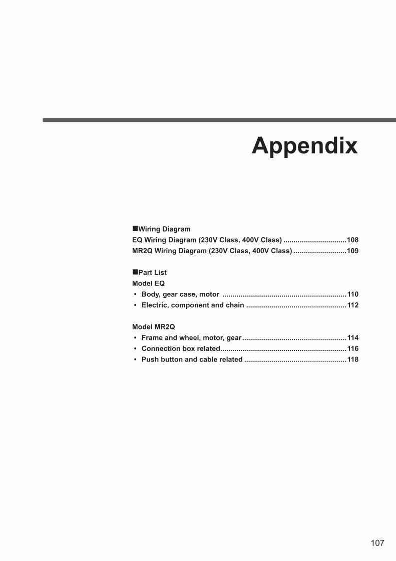
107
Appendix
Wiring DiagramEQ Wiring Diagram (230V Class, 400V Class) ................................108MR2Q Wiring Diagram (230V Class, 400V Class) ...........................109
Part ListModel EQ• Body, gear case, motor ...............................................................110• Electric, component and chain ...................................................112
Model MR2Q• Frame and wheel, motor, gear .....................................................114• Connection box related ................................................................116• Push button and cable related ....................................................118
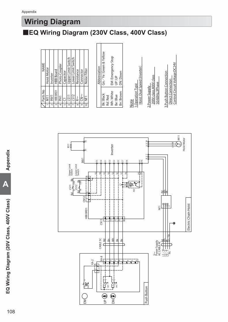
108
A
App
endi
xEQ
Wiri
ng D
iagr
am (2
0V C
lass
, 400
V C
lass
)
Wiring Diagram Appendix
■EQ Wiring Diagram (230V Class, 400V Class)
Not
e
2.Po
wer
Sup
ply
3.Pu
sh B
utto
n Co
nnec
tion
Dire
ct C
onne
ctio
n
1.O
pera
tion
Type
Hoi
st: D
ual S
peed(
Inve
rter
)
200V
cla
ss,4
00V
clas
s50
/60H
z,3P
hase
CABL
E 5C
AC C
ABLE
4C
Pow
er S
uppl
y3~
Push
But
ton12
11
SW0
SW2
13
2
SW1
13
2
Bk BeRd Bn Wh
XA-8
XA-2 3 5 682 471
12
Rd Wh
Bk Gn/
Ye
L1 L2/
SL3
/T
PE/R
UP
DN
EM
53
CN11
R1C1
PH1
S6
41 2
Low
er L
imit
Upp
er L
imit
H1
HC
L1 L2 L3
NF1
Elec
tric
Cha
in H
oist
Switc
h
S5 S4 S1 S3 S2 SC S7 S6Switc
h
Inve
rter
Hoi
st M
otorM
11
UV
W
Rd Wh
Bk
CN12
HBB
BRD
1
LS11
NC
COM
LS12
NC
COM
Rd
Rd 43
1
Bk Bk
25
RV
ST
UW
H1
HC
SC S7S4 S1 S2S5 S3INV1
B2B1
R11
Cont
rol C
ircui
t Vol
tage
:DC2
4V
HBB
BRD
1
CN~
LS12
R~LS11
PH1
C1M11
INV1
Part
s No
8 93 4 75 61 2
Upp
er L
imit
Switc
hLo
wer
Lim
it Sw
itch
Conn
ecto
r
HBB
Boa
rd
Resis
tanc
e
Phot
o Co
uple
rCa
paci
tor
Hoi
st M
otor
Inve
rter
NAM
E
Abbr
evia
tion
Gn/
Ye:
Gre
en &
Yel
low
Bk:
Blac
kRd
:Re
dW
h:W
hite
Be:
Blue
Bn:
Brow
n
EM:
Emer
genc
y St
opU
P:U
PD
N:D
own
NF1
Noi
se F
ilter
10
M 3~

109
Appendix
MR
2Q W
irring Diagram
(230V Class, 400V C
lass)
A
■MR2Q Wiring Diagram (230V Class, 400V Class)Pa
rts N
oN
AME
Hoi
st M
otor
M11
1 2 3 4 7 8 9
X~,C
N~
Conn
ecto
r
LS11
Upp
er L
imit
Switc
hLS
12Lo
wer
Lim
it Sw
itch
HBB
BRD
~H
BB B
oard
INV~
Inve
rter
M21
Trol
ley
Mot
or
TB~
Term
inal
Bl
ock
NF~
Noi
se F
ilter
Push
Bu
tton
Elec
tric
Cha
in H
oist
5 41 23
HBB
BRD
1
CABL
E 4CBk Or
Rd Bn Wh
Rd Wh
Bk Gn/
Ye
CN11
RdBk
Switc
hLS
11N
CCO
M
L1 L2 L3
M11
M 3~
UV
W
Hoi
st M
otor
S5 S4 S1 S3 S2 SC S7 S6 H1
HC
Low
er L
imit
Switc
h
Inve
rter
NF1
R1C1
PH1
BkRd
54
1CN
12 32
LS12
NC
COM
RV
ST
UW
S6 H1
HC
SC S7S4 S1 S2S5 S3INV1
B2B1
Upp
er L
imit
R11
2.Po
wer
Sup
ply
3.Pu
sh B
utto
n Co
nnec
tion
Dire
ct C
onne
ctio
n
200V
cla
ss,4
00V
clas
s50
/60H
z,3P
hase
1.O
pera
tion
Type
Hoi
st: D
ual S
peed(
Inve
rter
)
EM:
Emer
genc
y St
opU
P:U
PD
N:D
own
Not
e
Rd:
Red
Wh:
Whi
te
Bn:
Brow
nO
r:O
rang
eG
n:G
reen
Ye:
Yello
w
Be:
Blue
Gn/
Ye:
Gre
en/Y
ello
wAb
brev
iatio
nBk
:Bl
ack
R21
TB21
L1 L2 L3 PEG
n/Ye
Rd Wh
Bk
Gn/Ye
UV
WM
21
42
3
TB22
Rd Wh
Bk
R
B1 B2
L1 L2 L3
ST
3
BkRdWh
12
X22
UV
W
SW4
3
12
S6
CN11
PH1
C1R1
HCH1 H1
HC
HBB
BRD
2
INV2
S2
SC
S7
S6
S2
SC
S7
S4
S1
S3 S3
S1
S4
32
54
1
Or
BkBe
YeBn
68
75
4
SW0
12 11
X21
S5 S5
CN12
2 3 45 1
13
2
32
1 RdG
nW
h
CABL
E 8C
SW3
3
12
SW2
3
12
XA-8
XA-2
2
SW1
3
12
1
Trav
elU
PD
N
Mot
or A
ssy
CABL
E 4C
EM
Inve
rter
AC C
ABLE
4C
Pow
er S
uppl
y3~
CABL
E 5C
Mot
oriz
ed T
rolle
yCo
ntro
l Box
NF2
L1L2
L3BkWhRd
Rd Wh
Bk
12
R~Re
sista
nce
Cont
rol C
ircui
t Vol
tage
:DC2
4V
5PH
~Ph
oto
Coup
ler
6C~
Capa
cito
r
1110
Trol
ley:
Dua
l Spe
ed(In
vert
er)
M 3~

110
A
App
endi
xB
ody,
gea
r cas
e, m
otor
Parts ListAppendix
■Body, gear case, motor
4344
21
20
46
45
47 48
6
49
52
50
9
55
5453
51
A
A
40
42
41
4
5
1
23
7
10
B
B
C
C
8
28
27
25
26
AA
24
23
23
23 19
22
12
11
13
37
30
29
32
31
35 36
14
1538
391633
34
17
18

111
Appendix
Body, gear case, m
otor
A
Figure #
Part Number
Part Name
Quantity per unit
Part Code
RemarkEQ001IS EQ003IS EQ005IS EQ010IS
1 001 Suspension Eye 1 EQ1CI9001 ← ← EQ1DI9001 For KITO EQ trolley connection
2 121 Top pin 2 EQ1CI9121 ← ← EQ1DI91213 033 Machine screw socket bolt 2 J1BG1-0601010 ← ← ← For Top pin
4 5501 Body with stator 1 EQ1BUQ03I5A1 ← EQ1BUQ05I5A1 EQ1BUQ10I5A1 400V ClassEQ1BMC03I5A1 ← EQ1BMC05I5A1 EQ1BMC10I5A1 230V Class
5 238 Ball bearing 1 J1GR000-06202 ← ← J1GR0A0-063036 137 Set pin S 2 E6SE005S9120 ← ← ←7 820 Warning sticker HW 1 ER2CI9807 ← ← ←8 960 Name plate side E 1 ER1BS9960 ← ← ←9 1223 Friction clutch complete set 1 EQ1CG1223 EQ1CF1223 EQ1CI1223 EQ1DI122310 244 Oil seal 1 EQ1CI9244 ← ← EQ1DI9244 For Motor shaft11 241 Load sheave 1 EQ1CI9241 ← ← EQ1DI924112 242 Ball bearing 1 J1GR0C0-06005 ← ← J1GR0C0-06006 For Load sheave13 245 Oil seal 1 EQ1CI9245 ← ← EQ1DI9245 For Load sheave14 243 Ball bearing 1 J1GR0A0-06007 ← ← J1GR0A0-06009 For Load sheave15 207 Snap ring 1 JISR000-00062 ← ← JISR000-00075 For Bearing (load side)16 240 Load gear 1 EQ1CG9240 EQ1CF9240 EQ1CI9240 EQ1DI924017 208 Snap ring 1 JISS000-00034 ← ← JISS000-00040 For Load gear18 187 Packing 1 EQ1DI9187 ← ← EQ1DI918719 153 Cable holder 1 EQ1DI9153 ← ← ←
20 5505 Braking resistor assembly 1INV705Y16 ← INV705Y16 * INV715Y17 * 400V ClassINV705E16 ← INV705E16 * INV715E16 * 230V Class
21 194 Machine screw with spring washer
2 J1AP2-4001010 ← ← × For Braking resistor4 × × × J1AP2-400101022 151 Limit switch cord cover 1 EQ1CI9151 ← ← EQ1DI915123 152 Machine screw with spring
washer 5 J1AP2-4001010 ← ← ← For Limit switch cord cover, Cable holder
24 331 Chain guide 1 EQ1CI9331 ← ← EQ1DI9331AA 1333 Limit switch assembly 1 EQ1CI1333 ← ← EQ1DI133325 1060 Limit switch complete set 1 EQ1DI1060 ← ← ←26 333 Limit switch cover 1 EQ1CI9333 ← ← EQ1DI933327 335 Machine screw 2 J1AL2-4001010 ← ← ←28 165 Machine screw socket bolt 2 J1BG1-0802525 ← ← J1BG1-1003030 For Chain guide29 110 Gear case 1 EQ1CI9110 ← ← EQ1DI911030 239 Ball bearing 1 J1GR0A0-06200 ← ← J1GR0A0-0620131 133 Oil plug 1 E5FE003S9111 ← ← E5FE003S911132 136 Plug packing 1 E2YS005-9109 ← ← ←33 810 Name plate OF 1 ER2CS9849 ← ← ←34 815 Name plate SP 1 EQ1BMY10I9B6 ← ← ←35 167 Machine screw socket bolt 1 J1BG1-0603030 ← ← ← For Gear case36 162 Machine screw socket bolt 5 J1BG1-0605050 ← ← ← For Gear case37 116 Packing G 1 EQ1CI9116 ← ← EQ1DI911638 135 Oil plug B 1 WR2BS9135 ← ← ←39 173 Eyebolt packing 1 E2YS005-9116 ← ← ←40 107 Fan cover 1 EQ1CI9107 ← ← EQ1DI910741 164 Socket bolt 4 J1BE1-0501414 ← ← ← For Fan cover42 225 Toothed lock washer 4 J1WH012-10050 ← ← ← For Fan cover43 108 Fan 1 ER2BS9108 ← ← ER2CS910844 323 Snap ring 1 J1SS000-00013 ← ← ←45 106 Motor cover 1 EQ1CI9106 ← ← EQ1DI910646 163 Machine screw socket bolt 3 J1BG1-0605050 ← ← J1BG1-0604040 For Motor cover47 209 Ball bearing 1 J1GR0C0-06203 ← ← J1GR0C0-0600448 5212 Brake drum assembly 1 EQ1CI5212 ← ← EQ1DI521249 214 Brake spring 1 EQ1CF9214 ← EQ1CI9214 EQ1DI921450 324 O ring 1 J1OP011-00125 ← ← J1OP011-0016051 318 Collar 1 E5FE003S9506 ← ← E5FE005S950652 317 Thrust disc 2 E5FE003S9505 ← ← E5FE005S950553 503 Pull rotor 1 E5FE003S9503 ← ← E5FE005S950354 316 Coned disc spring 1 E5FE003S9504 ← ← E5FE005S950455 5502 Motor shaft with rotor 1 EQ1CF5502 ← EQ1CI5502 EQ1DI5502
* Braking resistor assembly of EQ005IS, EQ010IS, has been changed. This is only for LOT No. EQ1B -. Use Braking resistor assembly in combination with Inverter assembly . see page 113

112
A
App
endi
xEl
ectr
ic, c
ompo
nent
and
cha
inAppendix
Parts List (continued)
■Electric, component and chain

113
Appendix
Electric, component and chain
A
Figure #
Part Num
ber
Part Name
Quantity per unit
Part CodeRemark
EQ001IS EQ003IS EQ005IS EQ010IS
1 2104 Controller cover assembly 1 EQ1CI2104 ← ← EQ1DI21042 161 Socket bolt 4 J1BE1-0602525 ← ← ← For Controller cover3 224 Toothed lock washer 4 J1WH012-10060 ← ← ← For Controller cover4 800 Name plate B 1 EQ1BUQ01I9A3 EQ1BUQ03I9A3 EQ1BUQ05I9A3 EQ1BUQ10I9A35 935 Warning sticker E 1 ER2CS9937 ← ← ←
6 1571 Inverter assembly 1INV60FY44 INV60FY41 INV60FY47 * INV615Y44 * 400V ClassINV60FC44 INV60FC41 INV60FC47 * INV615C44 * 230V Class
7 508 HBB board 1 ECP91KB22 ← ← ←
8 191 Machine screw with spring washer 4 J1AP2-4001010 ← ← ← 400V Class× × × J1AP2-4001010 230V Class
2 J1AP2-4001010 ← ← × 230V Class9 1011 Bottom hook complete set 1 EQ1CG1011 EQ1CF1011 EQ1CI1011 EQ1DI101110 1002 Hook latch assembly 1 ER2CS1002 ← ← ER2DS100211 874 Load chain 1 KAZN056W0000 ← ← KAZN071W000012 054 Limiting plate 1 × × EQ1CI9054 EQ1DI905413 051 Chain spring 2 × × EQ1CI9051 EQ1DI905114 055 Spring guide 1 × × EQ1CI9055 EQ1DI905515 1041 Stopper assembly 1 ER1CS1041 ← ← ER1DS104116 1951 Lubricant tube assembly 1 ER2CS1951 ← ← ←A 1401 Chain container P complete set 1 EQ1CI1401 ← ← EQ1DI1401 Plastic container17 401 Chain container P 1 EQ1CI9401 ← ← EQ1DI940118 166 Socket bolt 1 J1BE1-0809028 ← ← J1BE1-0812028 For chain container19 226 Lever nut 1 C2BA100-9074 ← ← ← For chain containerB 1405 Chain container (15) complete set 1 EQ1CI1405 ← ← × Canvas container17 5405 Chain container (15) assembly 1 EQ1CI5405 ← ← ×18 166 Socket bolt 1 J1BE1-0809028 ← ← × For chain container19 226 Lever nut 1 C2BA100-9074 ← ← × For chain container
20 1521 Power supply cable assembly 1ZLZB11CQ1000 ← ← ←
ZLZB11AQ1000 ← ← ← Cable one size larger than the standard size
21 521 Cable 1Z2CU401-0000 ← ← ←Z2CU402-0000 ← ← ← Cable one size larger than
the standard size22 541 Cable support arm 1 ER1BS9541 ← ← ←
23 1542Cable support 12 assembly
1E7AX003S2822 ← ← ←E4YS005-2822 ← ← ← Cable one size larger than
the standard sizeCable support 14 assembly24 569 Holder A 1 ECP5924AA ← ← ←
25 574 Cable packing 1ECP6912AA ← ← ←
ECP6914AA ← ← ← Cable one size larger than the standard size
26 823 Name plate G 1 E6LE010S9806 ← ← ←27 542 Machine screw with spring washer 2 J1AP2-6001616 ← ← ← For Cable support arm28 1557 Push button cord EH complete set 1 ZLD0015F1000 ← ← ←29 557 Cable 1 Z3CA500-0000 ← ← ←30 1561 3 push button switch assembly 1 SWJ2200AA ← ← ←31 565 Warning tag PB 1 SWD9013AC ← ← ←32 566 Tag holder 1 E7SE003S9787 ← ← ←33 569 Holder A 1 ECP5924AA ← ← ←34 574 Cable packing 1 ECP6910AA ← ← ←35 535 Cord support (wire stopper) 1 ER1BS9534 ← ← ←36 536 Machine screw with spring washer 2 J1AP2-5001212 ← ← ← For Cord support37 891 Holder B 2 ECP5924AB ← ← ←38 892 Holder packing 2 ECP5924AQ ← ← ←39 893 Holder nut 2 ECP5924AD ← ← ←
40 102 Noise filter assembly 1 ER2BMY05I9C1 ← ← ← 400V ClassER2BMC05I9C1 ← ← ← 230V Class
41 103 Noise filter support 1 EQ1DI9103 ← ← ←42 192 Machine screw with spring washer 4 J1AP2-4000505 ← ← ← For Noise filter43 193 Machine screw with spring washer 2 J1AP2-4001010 ← ← ← For Noise filter support44 053 Cushion rubber 2 ER1CS9053 ← × ×45 1855 Oil pot F 1 ER1BS1855 ← ← ER1CS1855
* Inverter assembly of EQ005IS, EQ010IS, has been changed.This is only for LOT No. EQ1B -. Use Inverter assembly in combination with Braking resistor assembly. see page 111
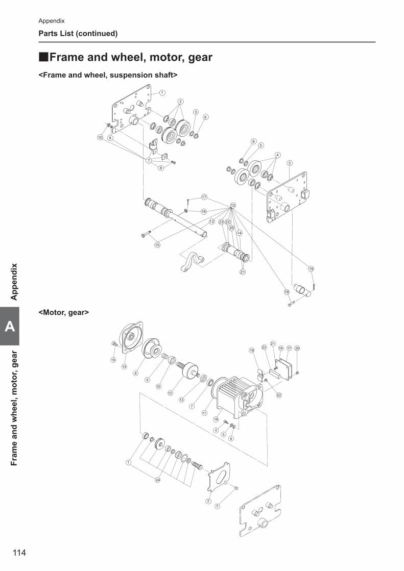
114
A
App
endi
xFr
ame
and
whe
el, m
otor
, gea
r
17
16
23 2220
14
12
3
4
1
2
10
5 6
21
15
13
9
19
18
7
8
5 6
15
14
8
9
10
12
13
7
11
19
22
2321
18 17 20
16
45
6
32
1
24
<Frame and wheel, suspension shaft>
<Motor, gear>
Appendix
Parts List (continued)
■Frame and wheel, motor, gear

115
Appendix
Frame and w
heel, motor, gear
A
Frame and wheel, suspension shaft
Figure #
Part Num
ber
Part Name
Quantity per unit
Part CodeRemark
MR2Q010IS1 5201 Side plate G assembly 1 MR1DS52012 1231 Track wheel G assembly 2 M6SE010S11013 5202 Side plate S assembly 1 MR1DS52024 1232 Track wheel S assembly 2 M6SE010S11025 235 Washer 4 T6GA010-9104 For track wheel G6 236 Snap ring 4 J1SS000-00015 For track wheel G7 1211 Side roller complete set 4 MR1DS1211SU_018 219 Bolt 8 J1BA1-08030309 220 Spring lock washer 8 J1WS011-20080
10 221 Nut 8 J1NA001-2008012 1151 Suspension shaft complete set (160) 1 MR2DI1151 Beam width: 58-163mm13 151 Suspension shaft (160) 1 MR1DS915114 102 Thick spacer 6 T4GA010-911615 103 Bolt 1 T1GA010-915316 104 Slotted nut 1 J1NL002-1010017 105 Split pin 1 J1PW01-02501818 106 Shaft stopper 1 T6GA020-915619 107 Split pin 1 J1PW02-04002021 109 Thin spacer 16 T6GA020-9117 125kg-500kg
14 1t23 113 Thin spacer L 2 M6FE010S911912 1136 Suspension shaft complete set (300) 1 MR2DI1136 125kg-500kg, Beam width: 164-305mm
1121 MR2DI1112 1t, Beam width: 164-305mm13 121 Suspension shaft (300) 1 M7SE010S918114 102 Thick spacer 9 T4GA010-911615 103 Bolt 1 T1GA010-915316 104 Slotted nut 1 J1NL002-1010017 105 Split pin 1 J1PW01-02501818 106 Shaft stopper 1 T6GA020-915619 107 Split pin 1 J1PW02-04002020 108 Fixing spacer (300) 2 M7SE010S918221 109 Thin spacer 8 T6GA020-9117 125kg-500kg
14 1t22 110 Thick spacer L 2 MR1DS9110 125kg-500kg23 113 Thin spacer L 2 MR2DI9113
Motor, gear
Figure #
Part Num
berPart Name
Quantity per unit
Part CodeRemark
MR2Q010IS2 248 Gear frame packing 1 MR1DS92483 249 Set pin 2 MR1DS9249 For gear frame and frame G4 250 Bolt 4 J1BA1-0802525 For gear frame. Integrated type with spring/flat waher is
available. (251 and 252 are not necessary.)5 251 Spring lock washer 4 J1WS011-20080 For gear frame6 252 Washer 4 J1WA011-00080 For gear frame7 253 Ball bearing 1 J1GR0C0-06204 For gear frame on motor side8 5261 Brake drum assembly 1 MR1DS52619 264 Brake spring 1 M3ES010-930410 265 Bumper 1 MR1DS926511 281 Guard 1 MR1DS928112 5291 Motor shaft with rotor 1 MR1DS529113 293 Oil seal 1 MR1DS929314 1301 Motor cover assembly 1 MR1DS130115 304 Socket bolt 4 J1BE1-0802222 For motor cover
16 5321 Motor frame with stator 1 MR2SJY10S5A2 400V ClassMR2SJC10S5A2 230V Class
17 324 Terminal cover 1 M6FE005S920618 325 Terminal cover packing 1 MR1DS932519 326 Coil cover 1 MR1DS932620 331 Machine screw with spring washer 4 J1AP2-5001010 For terminal cover21 332 Machine screw with spring washer 2 J1AW2-4002020 For terminal plate22 334 Machine screw with spring washer 1 J1AP2-4000808 For ground23 851 Terminal 6P 1 M6FE005S951624 1241 Gear complete set 1 MR1DS12411 247 Ball bearing 1 J1GR0B0-06002 For gear #3 on gear frame side

116
A
App
endi
xC
onne
ctio
n bo
x re
late
d
34
5
16
1721
15
1
20
2819
18
30
2225
24
913
14
43
6
7
1110 48
47
12 45
ylppuS rewoP rof
rofP
lortnoC nottuB hsu
29
5
54
3
2
43
27
36
31
843
44
23
26
3337
32
42
37 34
3541
46
41
38
39
40
Appendix
Pats List (continued)
■Connection box related

117
Appendix
Connection box related
A
Figure #
Part Num
ber
Part Name
Quantity per unit
Part CodeRemark
MR2Q010IS
1 1401 Connection box complete set 1MR2IVB10R1A4 400V ClassMR2IVC10R1A4 230V Class
2 341 Holder A 1 ECP5924AA3 342 Holder B 3 ECP5924AB4 343 Packing 3 ECP5924AC5 344 Holder nut 3 ECP5924AD6 347 Cord cover 1 E6LE010S96307 348 Machine screw with spring washer 4 J1AP2-5000808 For Cord cover8 349 Plate D 1 ECP5924AF9 401 Connection box 1 MR1DS940110 411 Connection box cover 1 MR1DS941111 421 Connection box packing 1 MR1DS942112 422 Machine screw with spring washer 4 J1AP2-5001010 For Connection box cover13 423 Spacer 4 M6SE010S951714 424 Machine screw with spring washer 4 J1AP2-8002020 For connecting Connection box and Frame
15 1445 Plate complete set 1MR2IVB10R1A5 400V ClassMR2IVC10R1A5 230V Class
16 441 Plate 1 MR2DI944417 443 Plate B 1 MR2DI944318 451 Machine screw with spring washer 3 J1AP2-4000808 For grounding19 452 Machine screw with spring washer 2 J1AW2-4000808 For Terminal 3P20 467 Machine screw with spring washer 4 J1AP2-4000808 For Plate B
21 1571 Inverter assembly 1INV602Y31 400V ClassINV604C31 230V Class
22 573 Braking resistor 1INV904Y34 400V ClassINV904E34 230V Class
23 5577 Noise filter assembly 1MR2ISY10R9C1 400V ClassMR2ISC10R9C1 230V Class
24 580 Machine screw with spring washer 4 J1AP2-4001010 For inverter, 400V Class2 For inverter, 230V Class
25 581 Machine screw with spring washer 2 J1AW2-4000808 For Braking resistor26 584 Machine screw with spring washer 4 J1AP2-4000808 For Noise filter27 716 HBB board 1 ECP91KB2228 853 Terminal 3P 1 ECP1403AA29 863 Inverter lead wire 1set MR2IVB10R9A530 454 Machine screw with spring washer 4 J1AP2-5001010 For Plate complete set31 1751 Relay cable P assembly 1 MR2DS2760 For power supply32 1570 Holder assembly 1 ECP5924BA 33 751 Cable 1 Z2CU401-000034 341 Holder A 1 ECP5924AA35 351 Cable packing 1 ECP6912AA36 1761 Relay cable S assembly 1 MR2DI2766 For operation37 341 Holder A 2 ECP5924AA 38 342 Holder B 1 ECP5924AB39 343 Packing 1 ECP5924AC40 344 Holder Nut 1 ECP5924AD41 351 Cable packing 2 ECP6910AA42 761 Cable 1 Z2CA500-000043 818 Cord cover packing 2 M7SE010S952744 820 Machine screw with spring washer 4 J1AP2-5000808 For Plate D45 701 Name plate B 1 EQ1BUQ10I9A3 1t
46 702 Name plate D 1EQ1BUQ01I9A6 125kgEQ1BUQ03I9A6 250kgEQ1BUQ05I9A6 500kg
47 834 Name plate SP 1 MR2IVB10R9B748 711 Warning seal E 1 ER2CS9937 Electric shock
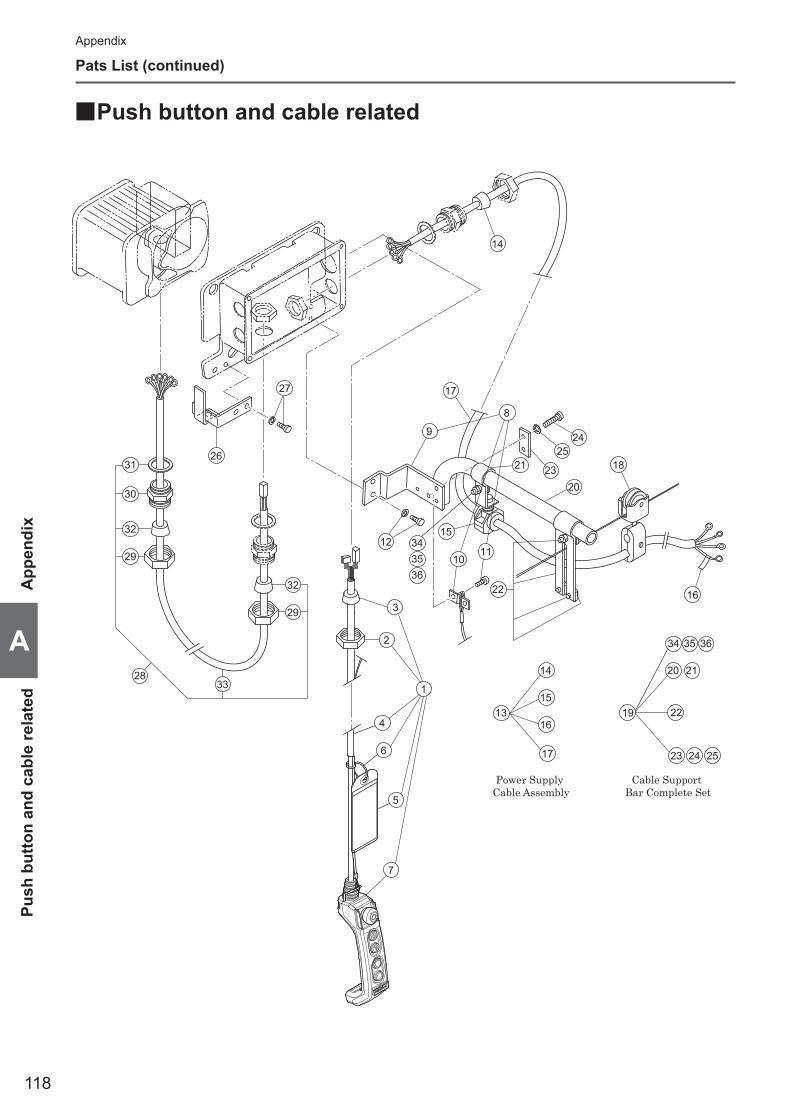
118
A
App
endi
xPu
sh b
utto
n an
d ca
ble
rela
ted
14
27
26
13
14
15
16
17
Power Supply Cable Assembly
19
20 21
22
23 24 25
Cable Support Bar Complete Set
3328
32
29
17
21
2425
2320
15
18
162232
29
30
31
12
9
8
1011
1
3
2
5
7
6
4
34 35 36
343536
Appendix
Pats List (continued)
■Push button and cable related

119
Appendix
Push button and cable related
A
Figure #
Part Num
ber
Part Name
Quantity per unit
Part CodeRemark
MR2Q010IS1 1781 Push button cord TR complete set 1 ZLDD01AF10002 341 Holder A 1 ECP5924AA3 351 Cable packing 1 ECP6912AA4 781 Cable 1 Z3CA800-00005 783 Warning tag PB 1 SWD9013AC6 784 Tag holder 1 E7SE003S97877 1801 5 push button switch assembly 1 SWJ2220AC8 1481 Bar holder assembly 1 MR1DS14819 481 Bar holder 1 MR1DS948110 816 Cord chain stopper 1 E6LE010S961411 817 Machine screw with spring washer 2 J1AP2-6001212 For cord chain stopper12 482 Socket bolt with spring washer 2 J1BG1-1002828 For bar holder13 1771 Power supply cable assembly 1 ZBZC12AJ100014 351 Cable packing 1 ECP6914AA15 1724 Cable support 14 assembly 1 E4YS005-282216 741 Name plate G 1 E6LE010S980617 771 Cable 1 Z2CU402-000018 1641 Cable hanger 14 assembly n E6AX003S152719 1491 Cable support bar complete set 1 MR1DS1491 For power supply cable20 491 Cable support bar 1 MR1DS949121 492 Cable support arm 1 MR1DS949222 1493 Wire guide assembly 1 MR1DS149323 501 Support bar holder (plate) 1 MR1DS950124 505 Bolt 2 J1BA2-0803030 For support bar holder (plate)25 506 Spring lock washer 2 J1WS012-20080 For support bar holder (plate)34 502 Bolt 1 J1BA2-080252535 503 Spring lock washer 1 J1WS012-2008036 504 Nut 1 J1NA002-20080
26511 Cable hanger pusher 1 MR1DS9511 For T-type hanger (Beam 75mm)512 Cable hanger pusher 1 MR1DS9512 For T-type hanger (Beam 100-150mm)
27 516 Socket bolt with spring washer 2 J1BG1-1002828 For cable hanger pusher 28 1791 Trolley cable assembly 1 MR2DS179129 341 Holder A 2 ECP5924AA30 342 Holder B 1 ECP5924AB31 343 Packing 1 ECP5924AC32 351 Cable packing 2 ECP6912AA33 791 Cable 1 Z2CU401-0000

120
W
WA
RR
AN
TY
WARRANTYKITO Corporation (“KITO”) extends the following warranty to the original purchaser (“Purchaser”) of new products manufactured by KITO (KITO’s Products).
1) KITO warrants that KITO's Products, when shipped, shall be free from defects in workmanship and/or materials under normal use and service and KITO shall, at the election of KITO, repair or replace free of charge any parts or items which are proven to have said defects, provided that all claims for defects under this warranty shall be made in writing immediately upon discovery and, if there is anything within a warranty period stated by your dealer from whom you purchased the products from the date of purchase of KITO's Products by Purchaser and provided, further, that defective parts or items shall be kept for examination by KITO or its authorized agents or returned to KITO's factory or authorized service center upon request by KITO.
2) KITO does not warrant components of products provided by other manufacturers. However to the extent possible, KITO will assign to Purchaser applicable warranties of such other manufacturers.
3) Except for the repair or replacement mentioned in (1) above which is KITO's sole liability and purchaser’s exclusive remedy under this warranty, KITO shall not be responsible for any other claims arising out of the purchase and use of KITO’s Products, regardless of whether Purchaser’s claims are based on breach of contract, tort or other theories, including claims for any damages whether direct, incidental or consequential.
4) This warranty is conditional upon the installation, maintenance and use of KITO’s Products pursuant to the product manuals prepared in accordance with content instructions by KITO. This warranty shall not apply to KITO’s Products which have been subject to negligence, misuse, abuse, misapplication or any improper use or combination or improper fittings, alignment or maintenance.
5) KITO shall not be responsible for any loss or damage caused by transportation, prolonged or improper storage or normal wear and tear of KITO’s Products for loss of operating time.
6) This warranty shall not apply to KITO’s Products which have been fitted with or repaired with parts, components or items not supplied or approved by KITO or which have been modified or altered.
THIS WARRANTY IS IN LIEU OF ALL OTHER WARRANTIES. EXPRESS OR IMPLIED, INCLUDING BUT NOT LIMITED TO ANY WARRANTY OF MERCHANTABILITY OR OF FITNESS FOR A PARTICULAR PURPOSE.

121
Mem
o

122
Mem
o Mem
o

1232
IntroductionThis electric hoist EQ is designed and manufactured for the purpose to lift and lower a load within a normal work environment. The motorized trolley MR2Q and the manual trolley are designed and manufactured for the purpose to move the lifted load laterally with the combination with the electric hoist. Movement of a load in a 3D direction such as up/down, forward/backward and right/left is also enabled by combining with a crane.
This Owner's Manual is intended for those operating the KITO electric hoist EQ and maintenance engineers (* pesonnel with expertise). Other than this manual, Disassembly/Reassembly Manual is also available for the maintenance engineers. Assign the maintenance engineers and use these materials for inspection and repair. Please contact the nearest distributor or KITO for these materials.
* A person who has a thorough knowledge of the structure and rolls concerning Electric chain block and is recognized as an expert by an entity.
Introduction ............................................................................................2
Safety Precautions ................................................................................4
Chapter 1 Handling the Product ..........................................................7
Chapter 2 Inspection ..........................................................................55
Chapter 3 Troubleshooting ................................................................87
Appendix ............................................................................................107
Warranty .............................................................................................120
EC Declaration of Conformity ..........................................................123
Table of Contents
■Disclaimer ● KITO shall not be liable for any damage incurred thereof due to natural disaster such as fire, earth quake and thunderbolt, conduct by third party, accident, willful conduct or negligence by customer, erroneous use and other use exceeding the operational condition.
● KITO shall not be liable for any incidental damage due to the use or non-use of the product such as the loss of business profit, suspension of business and damage of the lifted load.
● KITO shall not be liable for any damage arising from negligence of the contents in the Owner's Manual and the use of the product exceeding the scope of its specification.
● KITO shall not be liable for any damage arising from the malfunction due to the combination of the product with other devices in which KITO is not concerned.
● KITO shall be indemnified from any loss of life, bodily injury and property damage due to the use of our product for which it has passed 10 years since its delivery.
● KITO shall not be liable to supply the spare parts for the product for which it has passed for 15 years since the discontinue of the product.
DECLARATION OF CONFORMITY
We, KITO Corporation,2000 Tsuijiarai, Showa-cho,Nakakoma-gun, Yamanashi-ken, 409-3853, Japan
declare under our sole responsibility that the products:Electric chain hoist EQ, model EQfor use with or without the relevant trolley in capacity of 125kg to 1t to which this declaration relates is in conformity with the following EC directives and standards.
EC directives:Machinery Directive 2006/42/ECEMC Directive 2014/30/EULow Voltage Directive 2014/35/EU
Harmonized standards:EN ISO 12100:2010 Risk assessment and risk reductionEN 14492-2:2006+A1:2009 Power driven hoistsEN 818-7:2002+A1:2008 Short link chain for lifting purposesEN ISO 13850:2008 Emergency stopEN 60204-1:2006 Electrical equipment of machinesEN 61000-6-4:2007 Electromagnetic compatibility (Emission)EN 61000-6-2:2005 Electromagnetic compatibility (Immunity)
National standards:FEM 9.511:1986 Classification of mechanisms FEM 9.683:1995 Section of lifting and travel motors
EC DECLARATION OF CONFORMITY

Global Website: kito.com
EQ Series Electric Chain H
oist (125kg to 1t) Ow
ner's Manual
OM-EQ1ZZZ-CEE-03
To Customer
• Thank you for purchasing KITO Electric Hoist (EQ).• Operators and maintenance engineers are requested to read this manual.
After reading, please keep this manual at hand for future use. • This product is designed considering the environment protection. The product contains none of six hazardous
substances specified by European RoHS Directives nor asbestos.
Suspended Type (hoist only) : EQMotorized Trolley Type : EQMManual Trolley Type : EQSP
EQ Series Electric Chain Hoist (125kg to 1t)
Owner's Manual
Original Instruction
Utilizing 70% post-consumer recycled paper pulp
KITO Europe GmbH Heerdter Lohweg 93, D-40549 Düsseldorf, Germany TEL: +49-(0)211-528009-00 FAX: +49-(0)211-528009-59 E-mail: [email protected] URL: http://www.kito.net/
KITO corporation Tokyo Head Office: SHINJUKU NS Building 9F, 2-4-1, Nishi-Shinjuku, Shinjuku-ku, Tokyo 163-0809, Japan URL: http://kito.com/ Head Office & Factory: 2000 Tsuijiarai Showa-Cho, Nakakoma-Gun, Yamanashi 409-3853, Japan URL: http://kito.com/