EPSON” .files.support.epson.com/pdf/lq2550/lq2550u1.pdf · of your printer. Where to Get Help...
281
User’s Manual. _____--.--- EPSON” . Y465ss127mo
Transcript of EPSON” .files.support.epson.com/pdf/lq2550/lq2550u1.pdf · of your printer. Where to Get Help...
User’s Manual.
_____--.---
EPSON” .Y465ss127mo
EPSON®
L Q - 2 5 5 0
User’s Manual

FCC COMPLIANCE STATEMENTFOR AMERICAN USERS
This equipment generates and uses radio frequency energy and if not installed and used properly, thatis, in strict accordance with the manufacturer’s instructions, may cause interference to radio andtelevision reception. It has been type tested and found to comply with the limits for a Class Bcomputing device in accordance with the specifications in Subpart J of part 15 of FCC Rules, which aredesigned to provide reasonable protection against such interference in a residential installation.However, there is no guarantee that interference will not occur in a particular installation. If thisequipment does cause interference to radio or television reception, which can be determined by turningthe equipment off and on, the user is encouraged to try to correct the interference by one or more of thefollowing measures:- Reorient the receiving antenna- Relocate the printer with respect to the receiver- Plug the printer into a different outlet so that the printer and receiver are on different branch
circuits.
If necessary, the user should consult the dealer or an experienced radio/television technician foradditional suggestions. The user may find the following booklet prepared by the FederalCommunications Commission helpful:
“Television Interference Handbook.”
This booklet is available from the U.S. Government Printing Office, Washington, DC 20402. Stock No.004~00&00450-7.
WARNING
The connection of a non-shielded printer interface cable to this printer will invalidate the FCCCertification of this device and may cause interference levels which exceed the limits established by theFCC for this equipment. If this equipment has more than one interface connector, do not leave cablesconnected to unused interfaces.
IMPORTANT NOTICE
Seiko Epson Corporation and its affiliates (“Epson”) specifically disclaims all liability for problems andall damages which may result from the combination or use of Epson printers with software, hardwareproduct options, such as interface boards, or other items not supplied by Epson or otherwise designatedby Epson to be compatible with Epson printers. Epson further specifically disclaims all liability forproblems and all damages which may result from the unauthorized alteration or modification of Epsonprinters, whether or not such alteration or modification is accomplished by software, hardware or othermeans.
All rights reserved. No part of this publication may be reproduced, stored in a retrieval system, ortransmitted, in any form or by any means, mechanical, photocopying, recording or otherwise, withoutthe prior written permission of Seiko Epson Corporation. No patent liability is assumed with respect tothe use of the information contained herein. While every precaution has been taken in the preparationof this book, Seiko Epson Corporation assumes no responsibility for errors or omissions. Neither is anyliability assumed for damages resulting from the use of the information contained herein.
Epson America, Inc. shall not be liable against any damages or problems arising from the use ofany options or any consumable products other than those designated as Original Epson Products orEpson Approved Products by Seiko Epson Corporation.
Epson is a registered trademark of Seiko Epson Corporation.IBM is a registered trademark of International Business Machines CorporationMicrosoft is a registered trademark of Microsoft Corporation.
Copyright © 1988 by Seiko Epson CorporationNagano, Japan
ii

Table of Contents
Introduction . . . . . . . . . . . . . . . . . . . . . . . . . . . . . . . . . . . . . .Features . . . . . . . . . . . . . . . . . . . . . . . . . . . . . . . . . . . . . . . . . .Options . . . . . . . . . . . . . . . . . . . . . . . . . . . . . . . . . . . . . . . . . .About This Guide . . . . . . . . . . . . . . . . . . . . . . . . . . . . . . . . . .Where to Get Help . . . . . . . . . . . . . . . . . . . . . . . . . . . . . . . . .
1 Setting Up the Printer . . . . . . . . . . . . . . . . . . . . . . . . . . . . . . .Unpacking the Printer . . . . . . . . . . . . . . . . . . . . . . . . . . . . . .Choosing a Place for the Printer . . . . . . . . . . . . . . . . . . . . . .Assembling the Printer . . . . . . . . . . . . . . . . . . . . . . . . . . . . . .Testing the Printer . . . . . . . . . . . . . . . . . . . . . . . . . . . . . . . . . .Connecting the Printer to Your Computer . . . . . . . . . . . . . .Setting Up Your Application Software . . . . . . . . . . . . . . . . .
2 Paper Handling . . . . . . . . . . . . . . . . . . . . . . . . . . . . . . . . . . . .Using Single Sheets . . . . . . . . . . . . . . . . . . . . . . . . . . . . . . . . .Using Continuous Paper . . . . . . . . . . . . . . . . . . . . . . . . . . . .Switching between Continuous and Single Sheets . . . . . . . .Printing on Special Paper . . . . . . . . . . . . . . . . . . . . . . . . . . .
3 Using the Printer . . . . . . . . . . . . . . . . . . . . . . . . . . . . . . . . . . .Operating the Control Panel . . . . . . . . . . . . . . . . . . . . . . . . .SelecType Settings . . . . . . . . . . . . . . . . . . . . . . . . . . . . . . . . .Page Length . . . . . . . . . . . . . . . . . . . . . . . . . . . . . . . . . . . . . . .Skip Over Perforation . . . . . . . . . . . . . . . . . . . . . . . . . . . . . .Setting the Loading Position . . . . . . . . . . . . . . . . . . . . . . . . .Short Tear-Off . . . . . . . . . . . . . . . . . . . . . . . . . . . . . . . . . . . . .Selecting Typestyles . . . . . . . . . . . . . . . . . . . . . . . . . . . . . . . .Choosing an International Character Set . . . . . . . . . . . . . . .Choosing a Character Table . . . . . . . . . . . . . . . . . . . . . . . . .
1-1l-2l-6l-7
1-15l-221-27
2-12-22-5
2-162-22
3-13-23-8
3-263-283-303-313-333-393-40
Using Software and Graphics . . . . . . . . . . . . . . . . . . . . . .Using the LQ-2550 with Application Programs . . . . . . . .Computer-Printer Communication . . . . . . . . . . . . . . . . . .Enhancing Your Printing . . . . . . . . . . . . . . . . . . . . . . . . . . .Graphics . . . . . . . . . . . . . . . . . . . . . . . . . . . . . .User-Defined Characters . . . . . . . . . . . . . . . . . . . . . . . . . . .
Maintenance and Transportation . . . . . . . . . . . . . . . . . . .Cleaning the Printer . . . . . . . . . . . . . . . . . . . . . . . . . . . . . . .Replacing the Ribbon . . . . . . . . . . . . . . . . . . . . . . . . . . . . . .Transporting the Printer. . . . . . . . . . . . . . . . . . . . . . . . . . . .
Troubleshooting . . . . . . . . . . . . . . . . . . . . . . . . . . . . . . . . . .Problems and Solutions . . . . . . . . . . . . . . . . . . . . . . . . . . . .Data Dump Mode . . . . . . . . . . . . . . . . . . . . . . . . . . . . . . . . .
Using Printer Options . . . . . . . . . . . . . . . . . . . . . . . . . . . . .The Cut Sheet Feeder . . . . . . . . . . . . . . . . . . . . . . . . . . . . . .The Pull Tractor . . . . . . . . . . . . . . . . . . . . . . . . . . . . . . . . . . .Interface Boards . . . . . . . . . . . . . . . . . . . . . . . . . . . . . . . . . . .The Multi-Font Module . . . . . . . . . . . . . . . . . . . . . . . . . . . .
Command Summary . . . . . . . . . . . . . . . . . . . . . . . . . . . . . .Commands in Numerical Order . . . . . . . . . . . . . . . . . . . . .Commands Arranged by Topic. . . . . . . . . . . . . . . . . . . . . .
Appendix A . . . . . . . . . . . . . . . . . . . . . . . . . . . . . . . . . . . . . .Printer Specifications . . . . . . . . . . . . . . . . . . . . . . . . . . . . . .Double-Bin Cut Sheet Feeder Specifications. . . . . . . . . . .Interface Specifications . . . . . . . . . . . . . . . . . . . . . . . . . . . . .Initialization . . . . . . . . . . . . . . . . . . . . . . . . . . . . . . . . . . . . . .Default Settings . . . . . . . . . . . . . . . . . . . . . . . . . . . . . . . . . . .
Appendix B . . . . . . . . . . . . . . . . . . . . . . . . . . . . . . . . . . . . . .Proportional Width Table . . . . . . . . . . . . . . . . . . . . . . . . . .Character Tables . . . . . . . . . . . . . . . . . . . . . . . . . . . . . . . . . .
Glossary . . . . . . . . . . . . . . . . . . . . . . . . . . . . . . . . . . . . . . . . .
4-14-24-54-7
4-124-23
5-15-25-35-7
6-16-26-6
7-17-2
7-217-337-45
8-18-58-8
A-lA-2A-6A-9
A-13A-14
B-1B-2B-6
GL-1
Index . . . . . . . . . . . . . . . . . . . . . . . . . . . . . . . . . . . . . . . . . . . . Index-l
iv
Introduction
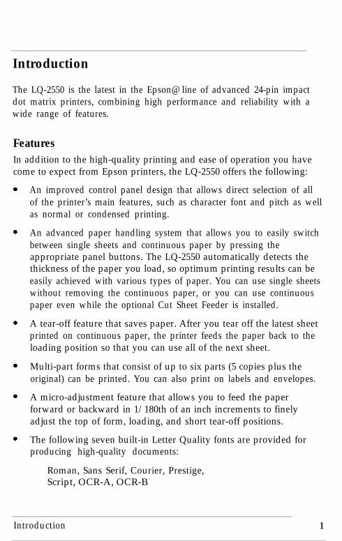
The LQ-2550 is the latest in the Epson@ line of advanced 24-pin impactdot matrix printers, combining high performance and reliability with awide range of features.
FeaturesIn addition to the high-quality printing and ease of operation you havecome to expect from Epson printers, the LQ-2550 offers the following:
An improved control panel design that allows direct selection of allof the printer’s main features, such as character font and pitch as wellas normal or condensed printing.
An advanced paper handling system that allows you to easily switchbetween single sheets and continuous paper by pressing theappropriate panel buttons. The LQ-2550 automatically detects thethickness of the paper you load, so optimum printing results can beeasily achieved with various types of paper. You can use single sheetswithout removing the continuous paper, or you can use continuouspaper even while the optional Cut Sheet Feeder is installed.
A tear-off feature that saves paper. After you tear off the latest sheetprinted on continuous paper, the printer feeds the paper back to theloading position so that you can use all of the next sheet.
Multi-part forms that consist of up to six parts (5 copies plus theoriginal) can be printed. You can also print on labels and envelopes.
A micro-adjustment feature that allows you to feed the paperforward or backward in 1/180th of an inch increments to finelyadjust the top of form, loading, and short tear-off positions.
The following seven built-in Letter Quality fonts are provided forproducing high-quality documents:
Roman, Sans Serif, Courier, Prestige,Script, OCR-A, OCR-B
Introduction 1
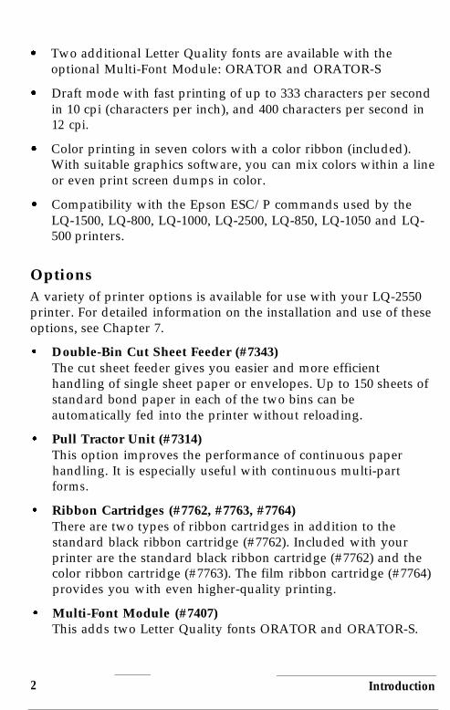
Two additional Letter Quality fonts are available with theoptional Multi-Font Module: ORATOR and ORATOR-S
Draft mode with fast printing of up to 333 characters per secondin 10 cpi (characters per inch), and 400 characters per second in12 cpi.
Color printing in seven colors with a color ribbon (included).With suitable graphics software, you can mix colors within a lineor even print screen dumps in color.
Compatibility with the Epson ESC/P commands used by theLQ-1500, LQ-800, LQ-1000, LQ-2500, LQ-850, LQ-1050 and LQ-500 printers.
OptionsA variety of printer options is available for use with your LQ-2550printer. For detailed information on the installation and use of theseoptions, see Chapter 7.
Double-Bin Cut Sheet Feeder (#7343)The cut sheet feeder gives you easier and more efficienthandling of single sheet paper or envelopes. Up to 150 sheets ofstandard bond paper in each of the two bins can beautomatically fed into the printer without reloading.
Pull Tractor Unit (#7314)This option improves the performance of continuous paperhandling. It is especially useful with continuous multi-partforms.
Ribbon Cartridges (#7762, #7763, #7764)There are two types of ribbon cartridges in addition to thestandard black ribbon cartridge (#7762). Included with yourprinter are the standard black ribbon cartridge (#7762) and thecolor ribbon cartridge (#7763). The film ribbon cartridge (#7764)provides you with even higher-quality printing.
Multi-Font Module (#7407)This adds two Letter Quality fonts ORATOR and ORATOR-S.
2 Introduction

LQ Printer Software (DCB-LQ2)This package features a driver and high-resolution fonts for usewith Microsoft@ Windows Presentation Manager version 2.0 andWindows/386 Presentation Manager. It lets you use your EpsonLQ printer to print pages created under the Microsoft Windowsoperating environment.
Optional Interface BoardsA number of optional interface boards can be used to supplement theLQ-2550’s built-in parallel and serial interfaces. Guidelines forchoosing the right interface and instructions on installing the boardsare given in Chapter 7.
About This GuideThis user’s guide provides fully illustrated, step-by-step instructions forsetting up and operating the LQ-2550 printer.
l Chapter 1 contains information on unpacking, setting up, testing,and connecting the printer, so be sure to read and follow theinstructions in this chapter first.
l Chapters 2 and 3 include important information on paper handlingand general printer operation. This information is necessary for theday-to-day operation of your printer.
l Chapter 4 contains information designed to help you get the mostfrom your printer. This section includes advice on the use ofsoftware, commands, graphics, and user-defined characters. Also,see Chapter 8 for a summary of printer commands.
l If the printer does not operate properly or the printed results are notwhat you expect, see Chapter 6 for a list of recommended solutions.
l Other chapters and appendixes contain information on generalmaintenance, use of the printer options, and specifications. You willalso find a glossary of printer terms and an index.
l At the back of this guide is a Quick Reference card with theinformation you are likely to need most often.
Introduction 3

Conventions used in this guide
WARNlNG: must be followed carefully to avoid damage toyour printer and computer.
Cautions: should be followed carefully to ensure that your printeroperates correctly.
Notes: contain important information and useful tips on the operationof your printer.
Where to Get HelpCustomer support and service for Epson products are provided by anetwork of authorized Epson Dealers and Customer Care Centersthroughout the United States. Epson America provides productinformation and support to its dealers and Customer Care Centers.
Therefore, we ask that you contact the business where youpurchased your Epson product to request assistance.If the peoplethere do not have the answer to your question, they can obtain itthrough our dealer support program.
Epson is confident that this policy will provide you with theassistance you need.
Call the Epson Consumer Information Center at l-800-922-8911 forthe following:
l The location of the nearest Epson dealerl The location of the nearest Customer Care Centerl Information on Epson User Groups.
To locate or purchase accessories or supplies, contact your nearestEpson dealer or call l-800-873-7766.
4 Introduction
Chapter 1
Setting Up the Printer
Unpacking the Printer . . . . . . . . . . . . . . . . . . . . . . . . . . . . . . . . . . . . . . . 1-2Removing the protective materials . . . . . . . . . . . . . . . . . . . . . . . . . . . 1-2
Choosing a Place for the Printer . . . . . . . . . . . . . . 1-6
Assembling the Printer . . . . . . . . . . . . . . . . . . . . . . . . . . . . . . . . . . . . . . . 1-7Installing the platen knob . . . . . . . . . . . . . . . . . . . . . . . . . . . . . . . . . . 1-7Installing the ribbon cartridge . . . . . . . . . . . . . . . . . . . . . . . . . . . . . . . 1-9Attaching the paper guide . . . . . . . . . . . . . . . . . . . . . . . . . . . . . . . . . 1-12
Testing the Printer . . . . . . . . . . . . . . . . . . . . . . . . . . . . . . . . . . . . . . . . . . 1-15Connecting to a power supply . . . . . . . . . . . . . . . . . . . . . . . . . . . . . 1-15Running the self test . . . . . . . . . . . . . . . . . . . . . . . . . . . . . . . . . . . . . . 1-16
Connecting the Printer to Your Computer . . . . . . . . . . . . . . . . . . . . . . 1-22The parallel interface . . . . . . . . . . . . . . . . . . . . . . . . . . . . . . . . . . . . . l-22The serial interface . . . . . . . . . . . . . . . . . . . . . . . . . . . . . . . . . . . . . . . 1-24
Setting Up Your Application Software . . . . . . . . . . . . . . . . . . . . . . . . . 1-27Choosing from a menu . . . . . . . . . . . . . . . . . . . . . . . . . . . . . . . . . . . 1-28
Setting Up the Printer 1-1
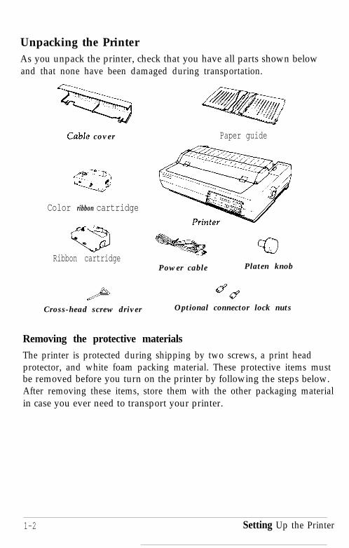
Unpacking the PrinterAs you unpack the printer, check that you have all parts shown belowand that none have been damaged during transportation.
Cabfe cover
Color ribbon cartridge
Ribbon cartridge
Cross-head screw driver
Paper guide
Power cable Platen knob
5YOptional connector lock nuts
Removing the protective materials
The printer is protected during shipping by two screws, a print headprotector, and white foam packing material. These protective items mustbe removed before you turn on the printer by following the steps below.After removing these items, store them with the other packaging materialin case you ever need to transport your printer.
1-2 Setting Up the Printer

1. Open the printer cover and raise it to an upright position; then lift itup and off.
2. Open the paper guide cover as shown in the illustration. Then raisethe cover slightly and lift the cover away from the printer at a slightupward angle.
Setting Up the Printer 1-3

3. Remove the print head protector and white foam packingmaterial.
4. Slide the print head all the way to the middle
Setting Up the Printer1-4

5. Using the enclosed cross-head screwdriver, remove the two redtransport screws as shown below.
6. Align the pins of the paper guide cover with the slots on the printerand attach the cover. Next, attach the printer cover.
Setting Up the Printer 1-5
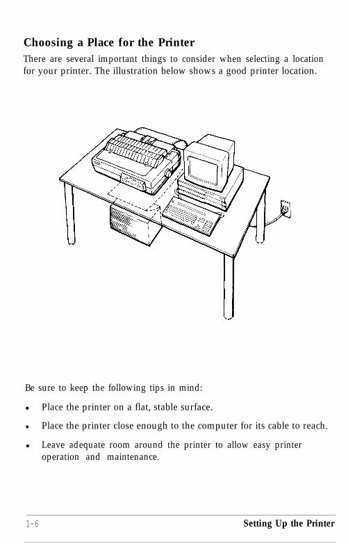
Choosing a Place for the PrinterThere are several important things to consider when selecting a locationfor your printer. The illustration below shows a good printer location.
Be sure to keep the following tips in mind:
l Place the printer on a flat, stable surface.
l Place the printer close enough to the computer for its cable to reach.
l Leave adequate room around the printer to allow easy printeroperation and maintenance.
1-6 Setting Up the Printer

Use a grounded outlet - one that has three holes to match thepower plug on the printer. Don’t use an adapter plug.
Avoid locations that are subject to direct sunlight, excessive heat,moisture, or dust.
Avoid using electrical outlets that are controlled by wall switches orautomatic timers. Accidental disruption of power can wipe outinformation in your computer’s and printer’s memory.
Avoid using outlets on the same circuit with large motors or otherappliances that might disturb the power supply.
Keep the entire computer system away from potential sources ofinterference, such as loudspeakers or the base units of cordlesstelephones.
Assembling the PrinterAfter you have decided on a location for your printer, it is necessary toinstall the platen knob, the ribbon cartridge, and the paper guide.Installation instructions for these three components are given below.
Installing the platen knobAfter you have decided on a location for your printer, the first step insetting it up is to install the platen knob.
You will find the platen knob packed in an indentation in the white foampacking material.
Setting Up the Printer 1-7

1. Insert the platen knob into the hole on the printer’s side and rotate ituntil it slips onto the shaft.
2. Press firmly on the knob until it fits against the printer case.
Caution: Using the platen knob to adjust the position of the paperinterferes with the automatic paper loading system and may cause apaper jam. If you need to adjust the position of the paper after it isloaded, use the micro-adjustment feature described in the section onsetting the loading position in Chapter 3.
1-8 Setting Up the Printer

Installing the ribbon cartridge
Your printer’s ribbon cartridges are designed for easy installation andremoval. The color ribbon cartridge, standard black ribbon cartridge,and optional film ribbon cartridge are all installed in the same way. (Acolor ribbon cartridge and standard black ribbon cartridge are includedwith your printer.) Install any of these ribbon cartridges as follows:
1. Open the printer cover and raise it to an upright position; then lift itup and off.
2. Open the paper guide cover as shown in the illustration. Then raisethe rear of the cover slightly and lift the cover away from the printerat a slight upward angle.
Setting Up the Printer 1-9
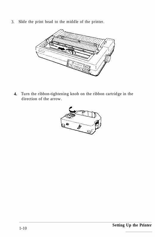
3. Slide the print head to the middle of the printer.
4. Turn the ribbon-tightening knob on the ribbon cartridge in thedirection of the arrow.
1-10Setting Up the Printer

5. Hold the ribbon cartridge while gently squeezing the two ridgedplastic tabs together; then lower it until it snaps into place. The sidehooks in the printer should fit into the slots on each side of theribbon cartridge.
6. Turn the ribbon tightening knob again to make sure the ribbonmoves freely.
Setting Up the Printer 1-11

7. Slide the print head from side to side to make sure that it movessmoothly. (Do not try to slide the print head by grasping the ribboncartridge.)
Attaching the paper guide
When you use single sheets, the paper guide functions to feed the papersmoothly and efficiently into the printer. Attach the paper guide usingthe following procedure.
Setting Up the Printer

1. Insert the paper guide pegs into slots on the printer.
2. Lean the paper guide back until it slips into place.
Setting Up the Printer 1-13

3. Align the pins of the paper guide cover with the slots on the printerand attach the cover.
4. Close the paper guide cover.
1-14 Setting Up the Printer

5. Attach the printer cover.
Testing the PrinterAt this point, you can use the built-in self test function to see that theprinter is working correctly even though it is not yet connected to acomputer.
Be sure to perform this test to make sure that your printer was notdamaged during shipping and to ensure that the ribbon is correctlyinstalled.
Before running the self test, you need to connect your printer to a powersupply and load a sheet of paper.
Connecting to a power supply
Before plugging in your printer, be sure that:
l The platen knob is installed.
l The ribbon cartridge is installed.
l The paper guide is attached.
l The paper guide cover is attached.l The printer cover is attached.
l The power switch on the left side of the printer is turned off.
Setting Up the Printer 1-15
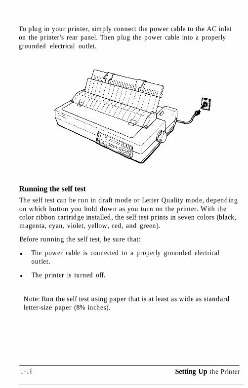
To plug in your printer, simply connect the power cable to the AC inleton the printer’s rear panel. Then plug the power cable into a properlygrounded electrical outlet.
Running the self test
The self test can be run in draft mode or Letter Quality mode, dependingon which button you hold down as you turn on the printer. With thecolor ribbon cartridge installed, the self test prints in seven colors (black,magenta, cyan, violet, yellow, red, and green).
Before running the self test, be sure that:
l The power cable is connected to a properly grounded electricaloutlet.
l The printer is turned off.
Note: Run the self test using paper that is at least as wide as standardletter-size paper (8% inches).
1-16 Setting Up the Printer

1. While holding down the LINE FEED button (draft mode) or the FORMFEED button (Letter Quality mode), turn on the printer. The printerbeeps three times and the POWER and PAPER OUT lights come on.
o PAPER OUT
2. Press the PAPER SELECT button until the FRICTION light comes on.
Setting Up the Printer 1-17
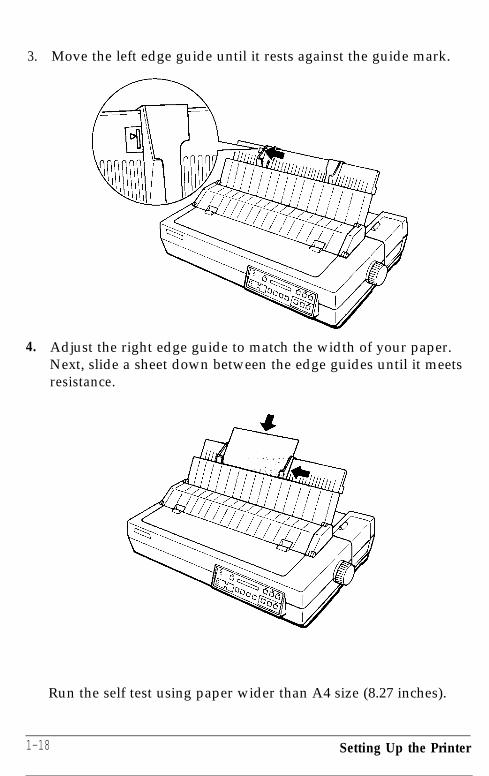
3. Move the left edge guide until it rests against the guide mark.
4. Adjust the right edge guide to match the width of your paper.Next, slide a sheet down between the edge guides until it meetsresistance.
Run the self test using paper wider than A4 size (8.27 inches).
1-18 Setting Up the Printer

5. Press the LOAD/EJECT button once to automatically load the paper.
6. Press the ON LINE button to start the self test.
Setting Up the Printer 1-19
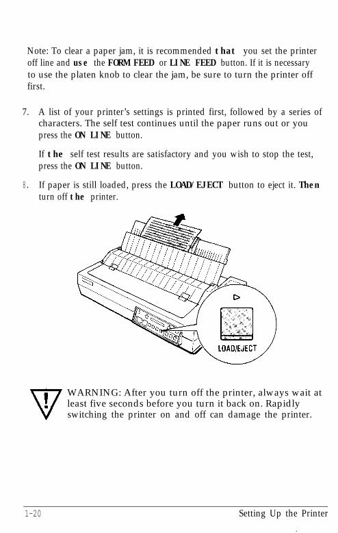
Note: To clear a paper jam, it is recommended that you set the printeroff line and use the FORM FEED or LINE FEED button. If it is necessaryto use the platen knob to clear the jam, be sure to turn the printer offfirst.
7. A list of your printer’s settings is printed first, followed by a series ofcharacters. The self test continues until the paper runs out or youpress the ON LINE button.
If the self test results are satisfactory and you wish to stop the test,press the ON LINE button.
8. If paper is still loaded, press the LOAD/EJECT button to eject it. Thenturn off the printer.
WARNING: After you turn off the printer, always wait atleast five seconds before you turn it back on. Rapidlyswitching the printer on and off can damage the printer.
1-20 Setting Up the Printer

Part of a typical self test in Letter Quality mode with a black ribboninstalled is shown in the following sample printout.
Self test in Letter Quality modeC u r r e n t s e t t i n g
FONT RomanPITCH lOCPICONDENSED O f fFORM LNGT r a c t o r 66LINEC S F bin1 132LINE,CSF b i n 2 132LINE1 " SKIP O f fAUTO TEAR OFF O f fLEFT MARGIN 0RIGHT MARGIN 136CC TABLE I t a l i cCOUNTRY USApy B i - d
k--
-a/O1234567,k/O12345678-./0123456789Courier
1 0 1 2 3 4 5 6 7 8 5 : ;jO123456789
<=>?@ABCDEFGHIJKLMNOPQRSTUVWX::;<=>?@ABCDEFGHIJKLMNOPQRSTUVWXY:
Note: When a black ribbon is installed, some lines of the self testare printed in double-strike mode. Also, when the optional cutsheet feeder is installed, the self test printout is slightly different.For details, see the section on the cut sheet feeder in Chapter 7.
Setting Up the Printer 1-21

Connecting the Printer to Your ComputerYour LQ-2550 has two separate interface connections: a parallel interfaceand an RS-232C compatible serial interface. If you are not sure whichone is required by your computer, check your computer manual for thisinformation.
If you have a suitable shielded cable, you should be able to connect tomost computers immediately.
The parallel interface
Connect the parallel interface cable as described below. Beforeconnecting the parallel interface cable, be sure that:
l The printer is turned off.
l The computer is turned off.
1. Plug the connector of the cable securely into the printer.
Iv
.WARNING: Do not plug more than one interface cableinto the printer at one time. This may damage the printer.
1-22 Setting Up the Printer

2. Squeeze the wire clips together until they lock in place on both sidesof the connector. (If you do not lock these clips into place, printedresults may be incorrect.)
3. If your cable has a ground wire, attach it to the ground connectorbeneath the interface connector.
Setting Up the Printer1-23
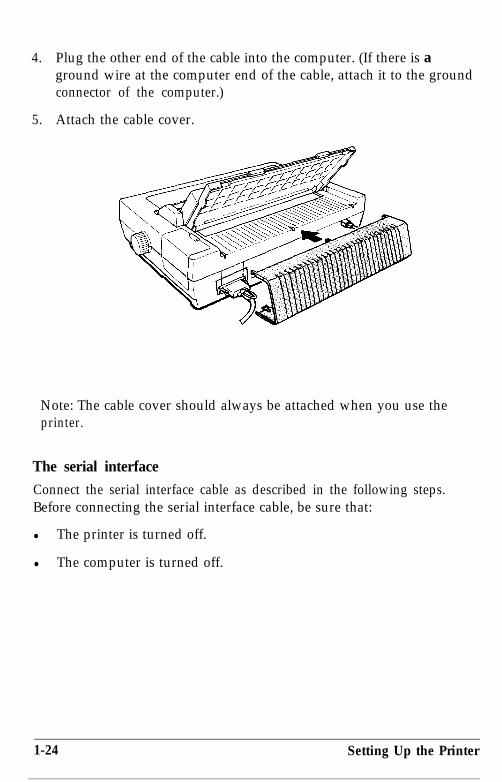
4. Plug the other end of the cable into the computer. (If there is aground wire at the computer end of the cable, attach it to the groundconnector of the computer.)
5. Attach the cable cover.
Note: The cable cover should always be attached when you use theprinter.
The serial interface
Connect the serial interface cable as described in the following steps.Before connecting the serial interface cable, be sure that:
l The printer is turned off.
l The computer is turned off.
1-24 Setting Up the Printer
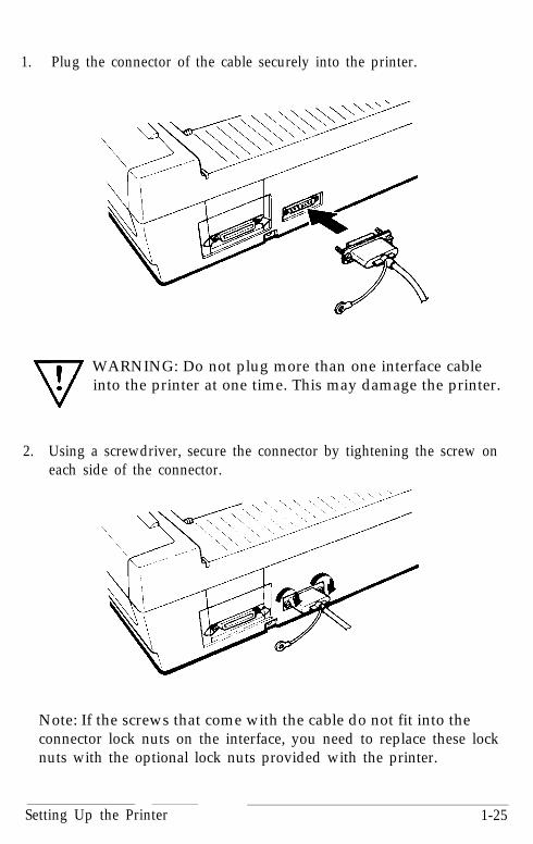
1. Plug the connector of the cable securely into the printer.
WARNING: Do not plug more than one interface cableinto the printer at one time. This may damage the printer.
2. Using a screwdriver, secure the connector by tightening the screw oneach side of the connector.
Note: If the screws that come with the cable do not fit into theconnector lock nuts on the interface, you need to replace these locknuts with the optional lock nuts provided with the printer.
Setting Up the Printer 1-25

3. If your cable has a ground wire, attach it to the ground connectorbeneath the interface connector.
4. Plug the other end of the cable into the computer. (If there is aground wire at the computer end of the cable, attach it to the groundconnector of the computer.)
1-26 Setting Up the Printer

5. Attach the cable cover.
Note: The cable cover should always be attached when you use theprinter.
Setting Up Your Application SoftwareNow that you have set up and tested the LQ-2550, you should make surethat it works with the application programs you want to use. Mostapplication programs let you specify the type of printer you are using sothat the program can take full advantage of the printer’s features. Manyof these programs provide an installation or setup section that presents alist of printers to choose from.
Setting Up the Printer 1-27

Choosing from a menu
Because the family of Epson printers shares many commands, you canuse an application program even if it does not list the LQ-2550 on itsprinter selection menu. If the LQ-2550 is not listed, select the first printeravailable on the following list:
LQ-2500LQ-1050 (LQ-850)LQ-1000 (LQ-800)LQ-500LQ-1500
If none of these printers is listed, select the first one available on thefollowing list:
LQ
EXFXLXRXMXEpson printerStandard printerDraft printer
If you are printing in color, it is recommended that you choose LQ-2550or LQ-2500.
To use all the features of the LQ-2550, however, it is best to use aprogram with the LQ-2550 on its menu. If your program does not listthis printer, contact the software manufacturer to see if an update isavailable. For further information on using software, see Chapter 4.
1-28 Setting Up the Printer

Chapter 2Paper Handling
Using Single Sheets . . . . . . . . . . . . . . . . . . . . . . . . . . . . . . . . . . . . . . . . . . 2-2Loading a sheet . . . . . . . . . . . . . . . . . . . . . . . . . . . . . . . . . . . . . . . . . . . 2-2Reloading during printing . . . . . . . . . . . . . . . . . . . . . . . . . . . . . . . . . . 2-5
Using Continuous Paper . . . . . . . . . . . . . . . . . . . . . . . . . . . . . . . . . . . . . 2-5Positioning your continuous paper supply . . . . . . . . . . . . . . . . . . . . . 2-5Loading continuous paper . . . . . . . . . . . . . . . . . . . . . . . . . . . . . . . . . . 2-6When you have finished printing . . . . . . . . . . . . . . . . . . . . . . . . . . . 2-13Reversing the paper to the standby position . . . . . . . . . . . . . . . . . . 2-14
Switching between Continuous and Single Sheets . . . . . . . . . . . . . . . . 2-16Switching to single sheets . . . . . . . . . . . . . . . . . . . . . . . . . . . . . . . . . . 2-16Switching back to continuous paper . . . . . . . . . . . . . . . . . . . . . . . . . 2-19
Printing on Special Paper . . . . . . . . . . . . . . . . . . . . . . . . . . . . . . . . . . . . 2-22Multi-part forms . . . . . . . . . . . . . . . . . . . . . . . . . . . . . . . . . . . . . . . . . 2-22Labels . . . . . . . . . . . . . . . . . . . . . . . . . . . . . . . . . . . . . . . . . . . . . . . . . . 2-23Envelopes . . . . . . . . . . . . . . . . . . . . . . . . . . . . . . . . . . . . . . . . . . . . .....2-26
Paper Handling 2-1

Using Single SheetsYour printer can accommodate single sheets from 7.2 to 14.3 incheswide.
Loading a sheetBefore loading a single sheet, be sure that:
l The printer cover is attached.
l The paper guide is attached, and the paper guide cover is attachedand closed.
1. Be sure that the printer is off line. If it is not, press the ON LINEbutton to set the printer off line.
cl0 POWER0 READYo PAPER OUTn ON LINE
aON LINE
2. Press the PAPER SELECT button until the FRICTION light comes on.
2-2 Paper Handling

3. Slide the left edge guide until it rests against the guide mark. Next,adjust the right edge guide to match the width of your paper.
4. Slide a sheet of paper down between the edge guides until it meetsresistance. At this time, the PAPER OUT light goes off.
Paper Handling 2-3

5. Press the LOAD/EJECT button once to automatically load the paper.
Note: If the platen turns without loading the paper, completelyremove the paper and re-insert it more firmly; then press theLOAD/EJECT button again.
6. Press the ON LINE button to set the printer on line.
771.WARNING: Never advance the paper using the platen knobexcept in the case of a paper jam or other paper feedproblem. Using the platen knob while the printer is onmay damage the printer, and it produces an error message(ERFi.OR 12 ) on the display. To clear this error you mustturn the printer off, take out the paper (using the platenknob if necessary), and turn the printer back on.
Press LOAD/EJECT to load the paper. If you need to adjustthe position of the paper after it is loaded, use the micro-adjustment feature described in the section on setting theloading position in Chapter 3.
2-4 Paper Handling

Reloading during printing
When you print a document more than one page long using single sheetpaper, the printer stops printing when it reaches the bottom of the paper.When this happens, either the ON LINE light goes off automatically or itmay remain on, depending on your application software. If the ON LINElight remains on, the first thing you should do is press the ON LINE buttonto take the printer off line.
Once the ON LINE light is off, remove the sheet that has just been printed(if necessary, press the FORM FEED button to eject the page) and load anew sheet. Press the ON LINE button to start printing the next page andfollow any additional prompts from your software.
Using Continuous PaperThe tractor built into the LQ-2550 is remarkably easy to load andoperate. Its low-profile design takes up little space and can handle paperwidths from 4 to 16 inches.
Positioning your continuous paper supplyAn important consideration for achieving smooth and accurate paperfeeding is the position of your continuous paper supply.
Three ways to position your printer and continuous paper are shownbelow.
Paper Handling 2-5
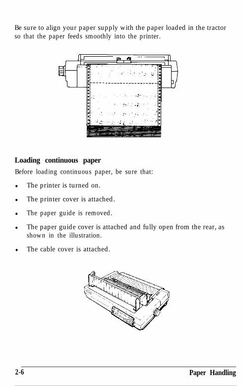
Be sure to align your paper supply with the paper loaded in the tractorso that the paper feeds smoothly into the printer.
Loading continuous paper
Before loading continuous paper, be sure that:
l The printer is turned on.
l The printer cover is attached.
l The paper guide is removed.
l The paper guide cover is attached and fully open from the rear, asshown in the illustration.
l The cable cover is attached.
2-6 Paper Handling
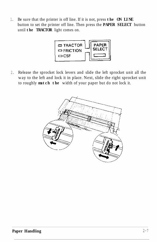
1. Be sure that the printer is off line. If it is not, press the ON LINEbutton to set the printer off line. Then press the PAPER SELECT buttonuntil the TRACTOR light comes on.
2. Release the sprocket lock levers and slide the left sprocket unit all theway to the left and lock it in place. Next, slide the right sprocket unitto roughly match the width of your paper but do not lock it.
Paper Handling 2-7
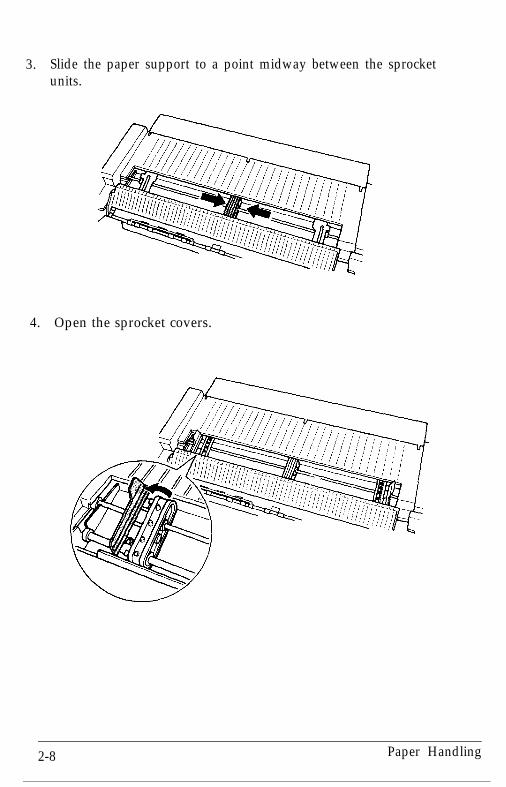
3. Slide the paper support to a point midway between the sprocketunits.
4. Open the sprocket covers.
2-8 Paper Handling

5. Fit the first four holes in the continuous paper over the pins of thesprocket units.
6. Close the sprocket covers.
Paper Handling2-9

7. Slide the right sprocket unit to a position where the paper is straightand has no wrinkles, and then lock it into place.
Note: Make sure the first sheet of paper has a clean, straight edge sothat the paper can feed smoothly into the printer.
8. Reattach the paper guide. Then slide the edge guides together so thatthey meet at about the middle of the paper’s width.
2-10 Paper Handling
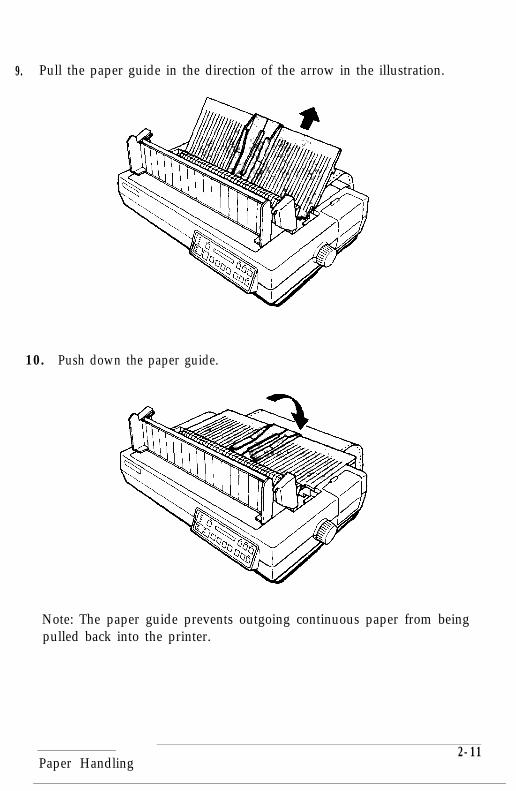
9. Pull the paper guide in the direction of the arrow in the illustration.
10. Push down the paper guide.
Note: The paper guide prevents outgoing continuous paper from beingpulled back into the printer.
Paper Handling2-11

11. Close the paper guide cover.
12. Press the LOAD/EJECT button to feed the paper to the loadingposition.
Note: If you press the LOAD/EJECT button when continuous paper isalready loaded, the paper is reversed to the standby position.
2-12 Paper Handling

13. Press the ON LINE button to set the printer on line.
The printer remembers this loading position and advances each page tothe same position. Never adjust the loading position using the platenknob. If you need to adjust the loading position, use the micro-adjustment feature. See the section on setting the loading position inChapter 3.
Note: Before you begin printing, be sure to check the page lengthand skip over perforation settings, and readjust the settings ifnecessary. See the sections on page length and skip over perforation inChapter 3.
Also, if you are using preprinted or multi-part forms or labels, or ifyou wish to obtain the highest quality graphics, it is recommendedthat you use the optional pull tractor. See the pull tractor section inChapter 7.
When you have finished printing
When you are ready to tear off the continuous paper printout, you caneither use the automatic short tear-off function or use the following steps.(For more information on the short tear-off function, see Chapter 3.)
1. After printing is completed, set the printer off line.
Paper Handling 2-13

2. Press the FORM FEED button to feed the paper forward. Then tear itoff at the perforation.
Note: If the perforation of the paper is not fed past the edge of thepaper guide the first time, press the FORM FEED button again. Do notuse the platen knob to feed the paper.
Reversing the paper to the standby position
After you have tom off the last page of printed paper, if you wish toreverse-feed the paper remaining in the printer to the standby position,follow the steps below.
When continuous paper is in the standby position, the holes at the top ofthe first sheet stay fitted over the pins of the sprocket unit. When thepaper is in this position, you can switch to single sheet paper (see theinstructions in this chapter), reload the continuous paper, or remove thecontinuous paper.
2-14 Paper Handling

Before reversing the paper, be sure that:
l The printer is turned on.
l The TRACTOR light on the control panel is on.
1. Check to see that the printer is off line. If it is not, press the ON LINEbutton to set the printer off line.
2. Press the LOAD/EJECT button once. This feeds the loaded paperbackward to its standby position. If the paper does not reach thisposition, the printer briefly displays Cannot Back Out. Press theLOAD/EJECT button as many times as necessary to back out the paperto its standby position. (Do not use the platen knob to back out thepaper. )
Paper Handling 2-15

Switching between Continuous and Single SheetsEven with continuous paper loaded in the printer, you can easily switchto single sheet printing without removing the continuous paper from thetractor.
Switching to single sheetsWhen you are finished printing on continuous paper, you can reverse-feed the paper to a standby position so you can switch to printing withsingle sheet paper.
Before you start, be sure that:
l The printer is off line.
l The paper guide cover is open as shown in the illustration.
l You tear off any printed sheets or extra blank sheets. (Make sure thepaper is not advanced past its loading position.)
2-16 Paper Handling

1. Press the PAPER SELECT button until the FRICTION light comes on. Thecontinuous paper is fed backward automatically to a standbyposition.
2. Raise the paper guide until it locks into place.
Paper Handling 2-17
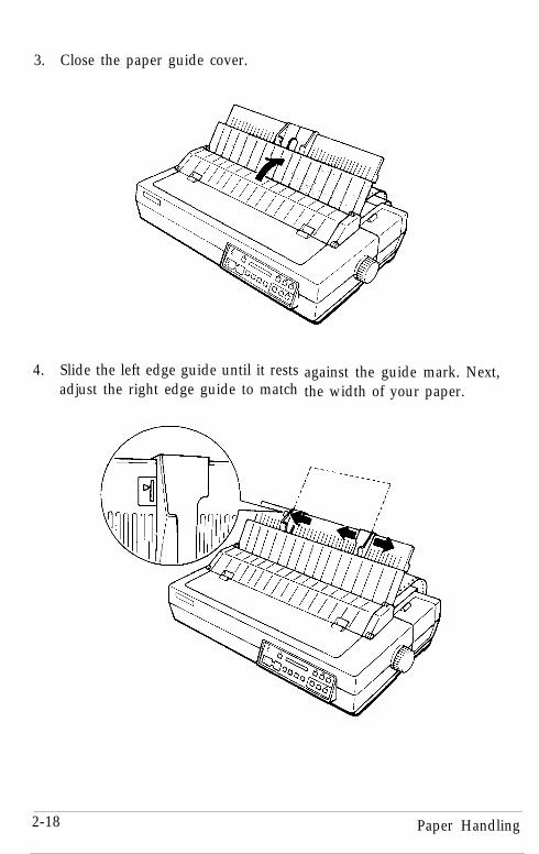
3. Close the paper guide cover.
4. Slide the left edge guide until it rests against the guide mark. Next,adjust the right edge guide to match the width of your paper.
2-18 Paper Handling

5. Slide a sheet of paper down between the edge guides until it meetsresistance.
6. Press the LOAD/EJECT button once to automatically load the paper.
7. Press the ON LINE button to set the printer on line.
Switching back to continuous paperIt is also easy to switch back to printing with continuous paper.
Paper Handling 2-19

Before switching back, be sure that:
l The printer is off line.
l The paper guide cover is open as shown in the illustration.
1. Press the PAPER SELECT button until the TRACTOR light comes on. If asingle sheet is loaded, it is ejected automatically and the continuouspaper is fed to the loading position.
2-20 Paper Handling
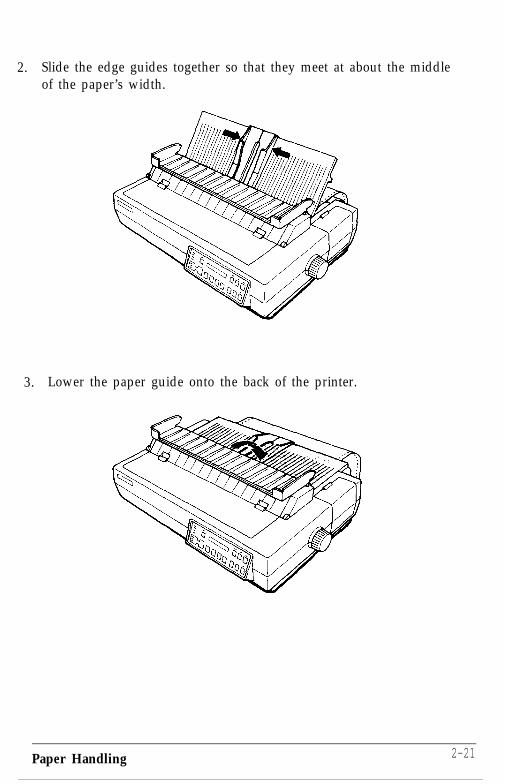
2. Slide the edge guides together so that they meet at about the middleof the paper’s width.
3. Lower the paper guide onto the back of the printer.
Paper Handling 2-21

4. Close the paper guide cover.
5. Press the ON LINE button to set the printer on line.
Printing on Special PaperIn addition to using single sheets and continuous paper, your printercan also print on a wide variety of paper types, including multi-partforms, labels, and envelopes. Your printer can sense the paperthickness and width automatically. You need not adjust the paperthickness manually.
Note: If you are printing preprinted or multi-part forms or labels, itis recommended that you use the optional pull tractor to print. Seethe pull tractor section in Chapter 7.
Also, when you print on multi-part forms, labels, or envelopes, besure that your application program settings keep the printingentirely within the printable area. That is, you should not print anycloser than one-half inch from either side of the paper for multi-part forms and labels. For information on the printable area forenvelopes, see page 2-27.
Multi-part formsWith the built-in tractor unit, your printer can print on continuousmulti-part forms. You can use multi-part forms that have up to six partsincluding the original.
2-22 Paper Handling

Multi-part paper is loaded the same way as continuous paper. Fordetails, see the section on loading continuous paper in this chapter.Before loading the multi-part forms, press the PAPER SELECT button untilthe TRACTOR light comes on.
WARNING: Do not load or print on multi-part forms if theFRICTION light or CSF light is on.
Labels
If you need to print labels, choose the type of label that is mounted on acontinuous backing sheet with sprocket holes for use with the tractor. Donot use single sheet labels on a shiny backing sheet because they almostalways slip a little if fed by friction alone.
You load labels the same way that you load continuous paper. See thesection on loading continuous paper in this chapter.
WARNING: Never feed labels backward through the printer.Labels can easily come off the backing and jam the printer.Also, never use the LOAD/EJECT button to eject labels. If alabel does become stuck in the printer mechanism, see yourauthorized Epson dealer for assistance.
Since labels are especially sensitive to temperature andhumidity, always use them under normal operatingconditions.
Paper Handling 2-23
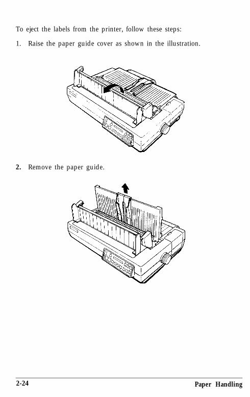
To eject the labels from the printer, follow these steps:
1. Raise the paper guide cover as shown in the illustration.
2. Remove the paper guide.
2-24 Paper Handling

3. Tear off the sheet of labels at the perforation behind the push tractor.
4. Press the ON LINE button to set the printer off line. Then press theFORM FEED button to eject the labels. (Remember not to use theLOAD/EJECT button to eject labels.)
Paper Handling 2-25

Envelopes
You can print on a variety of envelopes - including air mail, plain, orbond envelopes - using the single sheet loading feature described in thischapter. Chapter 7 describes using envelopes with the cut sheet feeder.
When loading an envelope, you may have to press down on it slightly.Then press the LOAD/EJECT button to load the envelope.
If it is necessary to eject the printed envelope, press the ON LINE button toset the printer off line. Then press the LOAD/EJECT button.
2-26 Paper Handling

WARNING: When you print on envelopes, be sure that yourapplication program settings keep the printing entirely withinthe printable area shown below.
8.5 mm(0.33”) or more
22 mm(0.87”) or more
3 m m(0.22”) or more
Note: If the printed results are faint, use the PLATEN GAP ADJUSTbutton to adjust the distance between the print head and the platen.
Paper Handling

Chapter 3
Using the Printer
Operating the Control Panel . . . . . . . . . . . . . . . . . . . . . . . . . . . . . . . . . . 3-2The display . . . . . . . . . . . . . . . . . . . . . . . . . . . . . . . . . . . . . . . . . . . . . . 3-2The lights.. . . . . . . . . . . . . . . . . . . . . . . . . . . . . . . . . . . . . . . . . . . . . . . 3-3The buttons . . . . . . . . . . . . . . . . . . . . . . . . . . . . . . . . . . . . . . . . . . . . . . 3-4Other control panel features . . . . . . . . . . . . . . . . . . . . . . . . . . . . . . . . 3-8
SelecType Settings . . . . . . . . . . . . . . . . . . . . . . . . . . . . . . . . . . . . . . . . . . 3-8Using SelecType . . . . . . . . . . . . . . . . . . . . . . . . . . . . . . . . . . . . . . . . . 3-10Selecting a main menu mode . . . . . . . . . . . . . . . . . . . . . . . . . . . . . . . 3-12LOAD MACRO . . . . . . . . . . . . . . . . . . . . . . . . . . . . . . . . . . . . . . . . . 3-13CHANGE MACRO . . . . . . . . . . . . . . . . . . . . . . . . . . . . . . . . . . . . . . 3-15CHANGE DEFAULTS . . . . . . . . . . . . . . . . . . . . . . . . . . . . . . . . . . . . 3-18PRINT OUT SETTINGS . . . . . . . . . . . . . . . . . . . . . . . . . . . . . . . . . . 3-23CLEAR ALL MACROS . . . . . . . . . . . . . . . . . . . . . . . . . . . . . . . . . . . 3-24
Page Length.. . . . . . . . . . . . . . . . . . . . . . . . . . . . . . . . . . . . . . . . . . . . . . 3-26
Skip Over Perforation . . . . . . . . . . . . . . . . . . . . . . . . . . . . . . . . . . . . . . 3-28
Setting the Loading Position . . . . . . . . . . . . . . . . . . . . . . . . . . . . . . . . . 3-30Adjusting the loading position . . . . . . . . . . . . . . . . . . . . . . . . . . . . . 3-30
Short Tear-Off . . . . . . . . . . . . . . . . . . . . . . . . . . . . . . . . . . . . . . . . . . . . . 3-31
Selecting Typestyles . . . . . . . . . . . . . . . . . . . . . . . . . . . . . . . . . . . . . . . . 3-33Fonts . . . . . . . . . . . . . . . . . . . . . . . . . . . . . . . . . . . . . . . . . . . . . . . . . . 3-34Pitch.................................................................................................................... 3-37Condensed mode . . . . . . . . . . . . . . . . . . . . . . . . . . . . . . . . . . . . . . . . 3-38
Choosing an International Character Set . . . . . . . . . . . . . . . . . . . . . . . 3-39
Choosing a Character Table . . . . . . . . . . . . . . . . . . . . . . . . . . . . . . . . . 3-40
Using the Printer 3-1

Operating the Control PanelThe LQ-2550 control panel is made up of three elements: the buttons,indicator lights, and Liquid Crystal Display (LCD). The buttons let youcontrol all of the main printer settings and paper handling functions, andthe indicator lights and display let you monitor the current status of theprinter.
The display
0 POWER0 READY0 PAPER OUT
o ON LINE
If any of the following states occur, the display shows the correspondingmessage.
The printer is out of paper.
The printer cover is open.
The print head has become hot. When theprint head cools, printing resumes and thismessage clears.
Paper is jammed. Turn the printer off andremove paper. If no paper is jammed, theprinter requires service.
Paper is crooked. Turn the printer off andremove paper. Turn the printer back on, andreload paper using the LOAD/EJECT button.
Paper was advanced using the platen knob.Turn the printer off and remove paper. Turnthe printer back on and reload paper usingthe LOAD/EJECT button.
3-2 Using the Printer

The lights
0 POWER a
0 READY13 PAPER OUTo ON LINE
ON LINE FORM FEED LINE FEE0 LOAOIEJECT
POWER (green):
READY (green):
PAPER OUT (red):
ON LINE (green):
TRACTOR (green):
FRICTION (green):
CSF (green):
CONDENSED (green):
TEAR OFF (orange):
MICRO FEED (orange):
Using the Printer
On when the printer is turned on andpower is supplied.
On when the printer is ready to acceptinput data. This light flickers while data isreceived.
On when the printer is out of paper.
On when the printer can receive and printdata from the computer. If this lightflickers, the print head is overheating.Printing resumes when the print headcools.
On when tractor feed is selected by thePAPER SELECT button.
On when friction feed is selected by thePAPER SELECT button.
On when cut sheet feeder mode is selectedby the PAPER SELECT button.
On when condensed mode is selected bythe CONDENSED button, SelecType setting,or software command.
On when tear-off mode is selected.
On when micro-adjustment feature isselected.
3-3

PLATEN GAP ADJUST : On when platen gap adjust mode is(orange) selected.
SelecType (orange): On when SelecType mode is selected.
4 A V b (yellow): These arrows prompt the user whenSelecType mode, tear-off mode, micro-feedmode, or platen gap adjust mode isselected.
The buttons
O N L I N E F O R M F E E D L I N E FEED LOAOIEJECT
ON LINE:
FORM FEED:
This button controls the printer’s on line/off line status. When the printer is on line,the ON LINE light on the left side of thecontrol panel is on and the printer canreceive and print data from the computer.In SelecType mode, this button may beused to change the SelecType settings.
When the printer is off line, this buttonejects a single sheet of paper or advancescontinuous paper to the top of the nextpage. In SelecType mode, this buttonchanges the SelecType settings.
3-4 Using the Printer

LINE FEED:
LOAD/EJECT:
When the printer is off line, this buttonfeeds the paper one line, or held down,feeds the paper continuously. In SelecTypemode, this button changes the SelecTypesettings.
When the printer is off line, this buttonloads or ejects the paper. In SelecTypemode, this button changes the SelecTypesettings.
FONT:
PITCH:
Hold down this button until the displayshows the desired font. Pressing the FONTbutton displays fonts in the followingorder:
Draft, Roman, Sans Serif, Courier,Prestige, Script, OCR-B, OCR-R,ORATOR, ORATOR-S
Orator and Orator-S are only available withthe optional Multi-Font Module. See thesection on fonts in this chapter for moreinformation.
Hold down this button until the displayshows the desired pitch. You can choose 10,12, or 15 CPI (characters per inch) orProportional. See the section on pitch in thischapter for more information.
Using the Printer 3-5

CONDENSED: Press this button to select either condensedor normal printing. The selected mode isdisplayed. In condensed mode, allcharacters are printed at approximately60% of their normal width. This modecannot be combined with 15 CPI (set by thePITCH button).
MICRO FEED:
PLATEN GAP ADJUST:
Turns on and off the micro-adjustmentfeature. In micro-feed mode, the LINE FEED(V) button is used to feed the paper slightlybackward and #he FORM FEED (A) button isused to feed the paper slightly forward toadjust the print position, short tear-offposition, or loading position. The sectionson short tear-off and adjusting the loadingposition in this chapter have moreinformation on this feature.
Selects or deselects the platen gap adjustmode. If the printing is too dark or toofaint, you can widen or narrow the platengap to achieve the desired printing results.When this mode is selected, the displaychanges to:
GhP . . . . ..DDDDD.
Press the ON LINE (4 ) button to widen thegap between the platen and print head.Press the LOAD/EJECT ( b) button to narrowthe gap. An increasing number of ) ‘sindicates a narrowing gap.
3-6 Using the Printer

SelecType:
TEAROFF:
PAPER SELECT:
Selects or deselects the SelecType mode. Whenthis mode is selected, the ON LINE (4), FORMFEED(A), LINE FEED (V),and LOAD/EJECT( .) buttons can be used as SelecType panelbuttons. The display lets you monitor theSelecType settings. See the section onSelecType in this chapter for details.
TEARwOFF
Press this button to feed the perforation ofcontinuous paper to the tear-off edge of theprinter. After tearing off the paper, press thisbutton again to feed the paper backward tothe loading position. You can also make thisfeature easier to use by setting the AUTO TEAROFF option with SelecType. See the shorttear-off section in this chapter for moreinformation.
When the printer is off line, press this buttonto select the paper handling system. Theselected system is shown on the display. Thepaper handling system is selected in thefollowing order:
Tractor, Friction, CSF Bin 1,CSF Bin 2
Using the Printer 3-7

Other control panel features
Self test: By holding down the FORM FEED button (fordraft mode) or LINE FEED button (for LetterQuality mode) while you turn on the printer,you can start the printer’s self test. The selftest printout lets you check the currentsettings and operating status of the printer.See the section on testing the printer inChapter 1 for more information.
Data dump: By holding down both the LINE FEED andFORM FEED buttons while you turn on theprinter, you turn on the data dump mode.This feature allows advanced users to findthe cause of communication problemsbetween the computer and printer. See thesection on the data dump mode in Chapter 6.
SelecType Settings
SelecType on the LQ-2550 brings a new dimension to printing. WithSelecType you can control almost every aspect of printer operation.
SelecType lets you:
l Use four preset macros - stored groups of settings that you canrecall with the touch of a button
l Replace the preset macros with your own custom-designedmacros
l Change up to 17 printer settings from SelecType
l Choose among the LQ-2550’s eight built-in fonts
l Print the LQ-2550’s settings with the touch of a button
l Monitor the LQ-2550’s settings with the LCD display
l Change the LQ-2550’s default settings without DIP switches.
3-8 Using the Printer

The four preset macros cover these general applications: Letter Qualityprinting/word processing, draft printing/word processing, spreadsheets,and graphics. You can also create your own macros with any of the LQ’ssettings.
MACRO #l
P r e s e t m a c r o # l i s s e t f o r L e t t e r Q u a l i t yp r i n t i n g / w o r d p r o c e s s i n g i n t h e R o m a n f o n t .It can be used for word processing or anyapplication where you want a polishedresult. You can also use enhancements andprint styles, including italic, emphasized,a n d d o u b l e - w i d t h ,
MACRO #2
P r e s e t m a c r o # 2 i s s e t f o r d r a f tp r i n t i n g / w o r d p r o c e s s i n g t o p r o d u c e h i g h -s p e e d , d r a f t q u a l i t y p r i n t i n g . I t c a n b eu s e d f o r w o r d p r o c e s s i n g t o p r i n t r o u g hd r a f t s , o r f o r a n y j o b y o u n e e d p r i n t e d i na h u r r y . Y o u c a n a l s o u s e e n h a n c e m e n t s a n dp r i n t s t y l e s , i n c l u d i n g itall’c, e m p h a s i z e d ,a n d d::::::l II::::::) II,.,..I! Ur::::r X. E::!: ~~~~~.~~ II,P,,II ::ii.. II::::::~ ‘I:::.. 1k11 ,.,,
MACRO #3
SALES REPORT
Jan Feb Mar Qr May Jun
J. Smith 784 548 475 648 074 6541. Jones 714 750 655 154 789 a85L. Williams 756 152 852 841 740 887
Using the Printer 3-9

MACRO #4
1
There are no switches to reset or commands to send. In fact, theLQ-2550 has no DIP switches. You simply load the macro you want,then print. All these functions can be controlled through SelecType.
Using SelecType
To enter SelecType mode, simply press the SelecType button.
0II
Selec Type
Before you use SelecType, make sure that the LQ-2550 is not printing.The printer must complete its print job before you enter SelecType. Ifyou have turned the printer off line during a print job, turn the printerback on line and let the LQ-2550 finish printing before you enterSelecType mode.
3-10 Using the Printer

Note: Your application may override your Selectype settings. Someapplication programs are designed to control the same settings youchoose with SelecType by sending certain software commands beforeprinting. Because these commands cancel SelecType settings, youshould use the program instead of SelecType to select the affectedsetting.
You can exit SelecType at any time by pressing this button once more.Note that you must exit SelecType before printing a document. If youpress the SelecType button after you set a macro but before you save it,those settings are temporarily used as current settings until the printer isturned off, but are cleared when the printer is turned back on.
The SelecType main menu lists the five modes that let you controlprinter functions and operations. The five main menu modes are:
:LrJflDMfKRO:
:CHflNGEl'MCRO:
:CHBNGEDEFAlJLTS
:PRINTOUTSETTINGS:
:CLEflRALLt'lC1CRDS:
This mode lets you load one of the fourmacros to accommodate your own printingneeds.
This mode lets you change the current printersettings (such as font and form length), withthe option of saving these changes to createyour own macros.
This mode lets you define the default settings(such as interface and baud rate) that will be ineffect each time you turn on the printer.
This mode prints out the current printersettings, the settings for the four macros, andthe default settings.
This mode returns all of the current printersettings, macro settings, and default settings tothe preset values.
Using the Printer 3-11

Following the arrow icons
When you are in the SelecType main menu, an : icon precedes the namesof each of the main menu modes. This icon indicates that you canchange modes by pressing either the ^ or V button. The F icon to theright of the mode name indicates that you can activate the mode bypressing the b button.
In general, the same applies when you are in a SelecType submenu. The: icon indicates that you can choose a different option (shown on the leftside of the display, such as FONT) by pressing the ^ or V button. TheF icon indicates that you can activate the option to select among itssettings (shown on the right side of the display, such as Roman and SansSe P i f) by pressing the F button. Once you have activated an option,you can choose among its settings by pressing the ^ or V button. Youcan select a setting by pressing the 4 button, and exit the option bypressing the 4 button again.
Selecting a main menu mode
Select one of the five main menu modes as follows:
1. Press the SelecType button.
Selec Type
a
The display briefly shows: SelecType MODE
Next, the display changes to: SLDfiDMfKRO b
3-12 Using the Printer

2. Press the A or V button to shift through the five modes as follows.
A
a
-
-
SLOADNFICRU b
:CHfiNGEMfKRO .I
SCHCINGEDEFAULTS b
:PRINTOUTSETTINGS b
:CLEFIRFtLLMCROS b
va
The instructions to follow show you how to select settings for thevarious options available for each main menu mode.
Note: After you have learned how to use the SelecType feature byreading through this chapter, you can use the Quick Reference card atthe back of this manual for summary information on SelecType, untilyou become accustomed to using this feature.
LOAD MACRO
The LOflD MfiCRO mode lets you load one of four preset macros or amacro you have created using the CHhNBE I’WICRO mode.
In the following sample, the settings of the four preset macros wereprinted with the PRINT OUT SETTINGS mode.
Using the Printer 3-13

FONTPITCHCONDENSEDFORM LNGTractorCSF bin1CSF bin21" SKIPAUTO TEAR OFFLEFT MARGINRIGHT MARGINCG TABLECOUNTRYPRINT DIR.COLOR
Macro #1 Macro #2 Macro #3 Macro t4ROIWXI Draft Draft ROlnEXIllOCPI lOCPI lOCPI lOCPI
Off Off On Off
66LINE132LINE132LINE
OffOff
0136
ItalicUSA
Bi-dBlack
66LINE132LINE132LINE
OffOff
0136
ItalicUSA
Bi-dBlack
66LINE132LINE132LINE
OffOff
0136
ItalicUSA
Bi-dBlack
BlLINE132LINE132LINE
OffOff
0136
ItalicUSA
Bi-dBlack
When you turn the printer on, one. of the four macros is loaded as thedefault macro. When you load another macro, the new macro’s settingsbecome the printer’s current settings.
To load a macro, perform the following steps.
1.
2.
3.
4.
Select the LUfiD NfKRU mode from the SelecType main menu. (Seethe instructions for selecting a main menu mode in the previoussection.)
The display shows: :LUfiD MACRO b
Activate the LOAD MfKRO mode by pressing the F button directlybeneath the display.
These two screens are alternately displayed:
LOF~DMIJCRU #r-t+
Il FIEURT LUflD,
Select the number of the macro to be loaded (1-4) by pressing the Aor V button.
Press the b button to load the selected macro. (To abort the loadmacro operation, press the 4 button.)
3-14 Using the Printer

If you have loaded a macro, the display briefly shows:
MfKRO#nLOfiDED
Next, the display changes to::LO~IDMFICRO b
You are now back at the SelecType main menu.
5. To switch to one of the other main menu modes, press the A or Vbutton. If you wish to exit SelecType mode, press the SelecTypebutton.
CHANGE MACRO
The CHANGE PlACRO mode lets you change the settings of whichevermacro is currently loaded. It also gives you the option of saving thesettings as any of the four rn-acres.
The settings available in CHhNGE MCRO mode are listed below.
FONT Roman, Sans Serif, Courier, Prestige,Script, OCR-B, OCR-FI, Draft., Orator(optional), Orator-S (optional)
PITCH
CONDENSED
FORM LENGTH*
1” SKIP
18 CPI, 12 CPI, 15 CPI*, Proportional** Some fonts cannot be printed in 15 CPI orproportional spacing. In this case, the pitch is notdisplayed.
On, Off
Tractor - 24 lines to 132 linesCSF B i n 1 - 24 lines to 132 linesCSF B i n 2 - 24 lines to 132 lines* The line spacing is in 1/6th of an inch units.
On, Off
fWTOTEfIROFF On, Off
LEFT l”MRCiIN* 0 to 80 columns
Using the Printer 3-15

RICiHTMARGIN*
CG TABLE
COUNTRY
1 to 136 columns*The column spacing is based on a pitch of 10 CPI.
I ta l ic , Graphic , Download
IJM, France, Germany, IJK, Denmarkl,Sweden, Italy, Spainl, Japan,Norway, Denmark2, Spain2, LatinAmerica, Korea, Legal
PRINT DIR. Bi-di rec t ional , Uni-di rec t ional
CiiLOR Black, Magenta, Cyan, Uil3let, Yellcfw,Red, Green
The changes you make are temporarily made to the current macro’ssettings (until you turn off the printer), but you can save the changes asany of the four macros. Changed macros that you save remain in effecteven after you turn off the printer.
The following example describes the procedure for changing the FONToption, but the other options (with the exception of FORM LENGTH) canbe changed in the same manner. (The procedure for setting FORMLENGTH is described later in this chapter.) The displays shown may bedifferent if your printer’s preset settings have been changed.
Note: The following options are described in more detail later in thischapter: FORMLENGTH, 1” SKIP, f&lTOTEAROFF, FONT, PITCH,COUNTRY, andCG TABLE.
3-16 Using the Printer

To change and save a macro, perform the steps described below.
1. Select the CHhNGE MACRD mode from the SelecType main menu. (Seethe instructions for selecting a main menu mode earlier in thischapter.)
The display shows: SCHCINGEMKRO b
2. Activate this mode by pressing the b button directly beneath thedisplay.
The display changes to: :FONT Roman b
Note: The + icon preceding FONT indicates that you can change to oneof the other options, such as right margin or color, by pressing the Vor A button to display the option.
3. To select a font, press the ä button.
The display changes to: 4 FONT Ronat-
4. Press the V button to shift through the available fonts. (Press the Abutton to shift through the fonts in reverse order.)
For the purposes of this example, display Sans Serif by pressingthe V button.
The display changes to: 4 FONT SansSerifI
5. Press the 4 button to select Sans Serif.
The display changes to: :FONT SansSerifb
Note: At this point you can again change the option at the left side ofthe display by pressing the A or V button. If you do this, begin againat step 3 to change the settings for the option.
Using the Printer 3-17
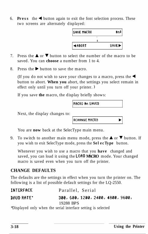
6. Press the 4 button again to exit the font selection process. Thesetwo screens are alternately displayed:
SCIUEMf3CRO #n:.&
4fiBORT SfV.JEb
7. Press the A or V button to select the number of the macro to besaved. You can choose a number from 1 to 4.
8. Press the b button to save the macro.
(If you do not wish to save your changes to a macro, press the 4button to abort. When you abort, the settings you select remain ineffect only until you turn off your printer. )
If you save the macro, the display briefly shows:
MflCRU#nSFIUED
Next, the display changes to::CHFINGEMFlCRU b
You are now back at the SelecType main menu.
9. To switch to another main menu mode, press the A or V button. Ifyou wish to exit SelecType mode, press the SelecType button.
Whenever you wish to use a macro that you have changed andsaved, you can load it using the LUAD MACRO mode. Your changedmacro is saved even when you turn off the printer.
CHANGE DEFAULTS
The defaults are the settings in effect when you turn the printer on. Thefollowing is a list of possible default settings for the LQ-2550.
INTERFRCE Para l l e l , Se r i a l
BAUDRflTE* 3G18, 68@, 12QB, 2488, 4888, 968Q,19288 BPS
*Displayed only when the serial interface setting is selected
3-18 Using the Printer

PARITY * None, Even, Odd, Ignore
FlUTOLINEFEED On, Off
DCl/DC3 Disable, Enable
DEFfYJLT MCR# #l, #21 #3, #4*Displayed only when the serial interface setting is selected
The LQ-2550 comes with preset default values, which can be printed outusing the PRINT GLJT SETTINGS mode. These default values are shownbelow.
D e f a u l t , set.t;ingINTERFACE P a r a l l e lBAUD RATE * 9 6 0 0 R P SPARITY * NoneAUTO L,INE FEED O f fDCl/DC3 D i s a b l eDEFAUI,T MACRO #3
If your computer has a parallel interface, the preset defaults should workcorrectly in most cases. You may wish to change the DEFAULT MACROsettings, however, to match your usual style of printing. Here are a fewadditional tips on setting the defaults.
l INTERFFICE: If your computer has a serial interface, you need tochange the interface setting to Serial. (If you are using an optionalinterface board, be sure that the interface setting is Pa r a 11 e 1,regardless of what type of interface it actually is. See the section oninterface boards in Chapter 7 for more information.)
l BFllJD RfiTE, Pf?RIT’r’: Set these only if you are using the serialinterface. (Be sure to first set the interface setting to Serial . BALJDRfiTE and PARITY do not display in SelecType unless the interface isset to Se r i a 1.) Check your computer manual for the correct baudrate and parity settings. Your computer and printer should be set tothe same baud rate and parity.
Using the Printer 3-19

f3UTO LINE FEED: This setting should remain at its default value(0 f f ) in most cases. Most applications send automatic line feeds atthe end of every line. If all of the lines are printing on top of eachother, then set FIIJTO LINE FEED to On.
DC 1 /DC3: This setting should also be left at its default value(Disable) in most cases. See these codes in Chapter 8 for moreinformation.
DEFWJLT MfKRO: This setting controls which macro is loaded whenyou turn on the printer.
To change and save the default settings, perform the steps listed below.The following example describes the procedure for changing theinterface, baud rate, and parity for a serial interface, but all the otheroptions can be changed in the same manner. If you are changing onlyone option, follow steps 1 - 4 and 13 - 17 only.
The displays shown may be different if your printer’s preset settings havebeen changed.
Note: Your new default settings do not take effect until you turn theprinter off and then back on.
1. Select the CHfINGE DEFfWLTS mode from the SelecType main menu.
The display shows: SCHfiNGEDEFAULTS b
2. Activate this mode by pressing the b button directly beneath thedisplay.
The display changes to: SINTERFCICE Parallel b
Note: If you wish to change an option other than INTERFfKE, pressthe A or V button.
3-20 Using the Printer

3. Press the F button to indicate that you wish to change the setting.
The display changes to: 4INTERFRCE P a r a l l e l :
4. Press the A or V button to switch the display to Se r i a 1.
The display changes to: ) 4 INTERFIXE Serial:1
5. Press the 4 button.
The display changes to: :INTERFf%E Serial,
Note: If you are changing only one option, skip to step 14 at thispoint. The other steps show you how to change two other options,following the same method given for the INTERFACE option.
6. Press the V button to switch the display to BAIJD Rf3TE.
The display changes to: :BFIUDRflTE 9600BPSb
7. Press the F button.
The display changes to: 4BfOJD RF1TE 9600BPS:
8. Press the A or V button to set the baud rate. In this example, thebaud rate is reset to 2400 BPS.
The display changes to: 4BfiUD RFITE 2400BPS:
9. Press the 4 button.
The display changes to: :EHJD R~ITE 2400BPSb
10. Press the V button to switch the display to PflRITY.
The display shows: SPhRITY None,
Using the Printer 3-21

11. Press the b button.
The display changes to: 4PFIRITY None:
12. Press the A or V button to select the parity. In this example, Evenparity is selected.
The display changes to: 4PFIRITY Even:
13. Press the 4 button.
The display changes to: ISPF~RITY Even,\
14. Press the 4 button again to exit this option.
The display alternates between these two menus:IwEDEF~~uLTS 1
4flBORT SfiUEb
15. Press the b button to save the defaults. (If you do not wish to savethe setting, press the 4 button.)
If you saved the defaults, the display briefly shows:DEFflULTSSAUED
It then briefly changes to: PLEMETURNOFF
This reminds you to turn your printer off and back on again to letthe changes in default settings take effect.
Finally, it changes to: :CHflNGEDEFiWLTS .I
You are now back at the SelecType main menu.
16. To switch to another main menu mode, press the A or V button. Ifyou wish to exit SelecType mode, press the SelecType button.
17. Turn your printer off and back on again to allow your new defaultsettings to take effect.
3-22 Using the Printer

PRINT OUT SETTINGS
The PRINT ClllT SETTINGS mode gives you an immediate printout ofthe current printer settings, the four macro settings, and the defaultsettings.
This mode is an invaluable tool that lets you check the macro settingsand defaults to decide if there is anything you want to change. It alsolets you verify changes you make to these settings with SelecType.
To use this mode, make sure the printer is loaded with paper and isfinished printing. Then follow the steps below.
1. Select the PRINT OUT SETTINGS mode from the SelecType mainmenu.
The display changes to: :PRINTUUTSETTINGS b
2. Activate this mode by pressing the b button.
The display changes to: 4fiBURT PRINT,
3. Press the b button to print.
If you do not wish to print, press the 4 button. (You can also pressthe 4 button to abort while printing is in progress.)
Caution: Always make sure that paper is loaded before you enter thePRINT OUT SETTINGS mode.
When printing is complete, the display changes to::PRINTOUTSETTINGS b
You are now back at the SelecType main menu.
4. To switch to another main menu mode, press the A or V button. Ifyou wish to exit SelecType mode, press the SelecType button.
Using the Printer 3-23

A sample printout made in the PRINT DUT SETTINGS mode isshown below. This printout shows the preset macros and defaultsettings.
CUrIFONTPITCHCONDENSEDFORM LNGTractorCSF bin1CSF bin21" SKIPAUTO TEAR OFFLEFT MARGINRIGHT MARGINCG TABLECOUNTRYPRINT DIR.COLOR
FONTPITCHCONDENSEDFORM LNGTractorCSF bin1CSF bin21" SKIPAUTO TEAR OFFLEFT MARGINRIGHT MARGINCG TABLECOUNTRYPRINT DIR.COLOR
Ymt settingRomanIOCPIOff
66LINE132LINE132LINE
OffOff
0136
ItalicUSA
Bi-dBlack
Macro #1RomanlOCPI
Off
Macro #2DraftlOCPIOff
66LINE 66LINE132LINE 132LINE132LINE 132LINE
Off OffOff Off
0 0136 136
Italic ItalicUSA USA
Bi-d Bi-dBlack Black
Macro f3DraftlOCPI
On
66LINE132LINE132LINE
OffOff
0136
ItalicUSA
Bi-dBlack
Macro 84RomanlOCPIOff
5lLINE132LINE132LINE
OffOff
0136
ItalicUSA
Bi-dBlack
Default settingINTERFACE ParallelBAUD RATE * 9600BPSPARITY * NoneAUTO LINE FEED OffDCl/DCB DisableDEFAULT MACRO t1
CLEAR ALL MACROS
This mode allows you to return all of the current printer settings, macrosettings, and default settings to the preset values. It also gives you theoption of clearing only the macro settings or only the default settings.
3-24 Using the Printer

Caution: This mode erases any custom-designed macros and defaultsettings that you have set and replaces them with the original settings.
To use the CLEAR flLL PlflCROS mode, follow the steps below.
1. Select the CLEflR flLL MCROS mode from the SelecType main menu.
The display changes to: :CLEFIRFILLMf3CROS b
2. Activate this mode by pressing the b button.
The display changes to: 4FlBORT CLEfiR.
Press the b button to clear all macros and return them to theirpreset values.
If you do not wish to clear all macros, press the 4 button.
If you chose to clear all macros, the display briefly shows:FILLtlfKROSCLEARED
It briefly changes to: CLEhRDEFfVJLTS
Then, the display changes to: 4 FtBORT CLEi?R,
3. Press the b button to clear the default settings. (If you do not wishto clear the default settings, press the 4 button.)
If you clear the defaults, the display briefly shows:DEFAULTSCLEfiRED
It briefly changes to: PLEASETIJRNCFF
This reminds you to turn your printer off and back on again to letyour changes take effect.
Then, it changes to: :CLEFIRFlLLMfXRUS b
You are now back at the SelecType main menu.
Using the Printer 3-25
4. To switch to another main menu mode, press the A or V button. Ifyou wish to exit SelecType mode, press the SelecType button.
5. Turn the printer off and back on again to allow the settings to takeeffect.
Page LengthThe SelecType function also enables you to set the page length of paperused with the tractor feed system or the cut sheet feeder. The page lengthcan be set in 1/6th of an inch units within a range of 24 lines to 132 lines.Be sure that the page length is correctly set for the type of paper feedsystem you are using. If you are using the cut sheet feeder, the pagelength is automatically set and memorized when you run the printer’sbuilt-in self test. However, you can use this Selectype feature to overridethis setting.
If you are using friction feed, it is not necessary to set page length withSelecType. However, be sure to select the correct page length with yourapplication software. Also, if possible, select the hand-fed or single sheetmode with your software. If your software gives you the option ofsending a form feed at the end of a page, select that capability as well.
To set the page length using SelecType, follow the steps below to set theFORM LENGTH option. The displays shown may be different if yourprinter’s preset settings have been changed.
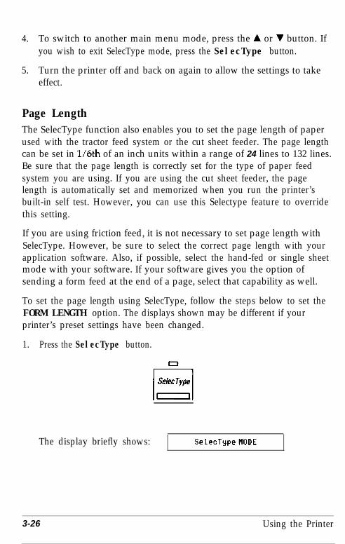
1. Press the SelecType button.
The display briefly shows: SclecTypeMODE
3-26 Using the Printer

Next, the display changes to::LOFIDMFlCRU b
2. Press the V button.
The display changes to: SCHANGEMACRU b
3. Press the b button.
The display changes to: :FONT Roman,
4. Press the A or V button to locate the FORM LENGTH option.
The display shows: SFORbl LNG Tractor,
5. Press the b button.
The display changes to: STractor 66LINEb
6. To change form length for tractor feed, press the b button.
(To change form length for the cut sheet feeder, first press the Vbutton. To set CSF bin 2, press the V button once more. Then pressthe b button.)
If you are changing form length for the tractor feed, the displaychanges to:
4Tractor 66LINE:
(If you are changing form length for a cut sheet feeder, the binnumber and form length are displayed.)
7. Press the A or V button to set the desired number of lines. In thisexample, the page length is set to 72 lines for the tractor feed.
The display shows: 4Tractor 72LINES
8. Press the 4 button.
The display shows::Tractor 72LINEb
Using the Printer 3-27

9. Press the 4 button again.
The display changes to: SFORfl LNG Tractor,
10. Press the 4 button once more.
These two screens are alternately displayed:
SFlUEMACRO.
#nt
4
4FlBORT SF1UEb
11. Press the A or V button to select the number of the macro to besaved (1-4).
12. Press the b button to save the macro. (If you do not wish to saveyour changes to a macro, press the 4 button.)
If you saved the macro, the display briefly shows:
MCR@#nSFIUED
The display then changes to:
I: CHf+NGEMi9CRO .I
You are now back at the SelecType main menu.
13. If you wish to exit the SelecType mode, press the SelecType button.
Skip Over PerforationBy adjusting the SelecType 1” SKIP option, you can set skip overperforation to ON or OFF. If this feature is on when you use continuouspaper, a one-inch margin is provided between the last printed line on onepage and the initial printable line on the next page so that the printerskips over the perforation. This feature is very convenient if yourapplication program does not provide top and bottom margins.
3-28 Using the Printer
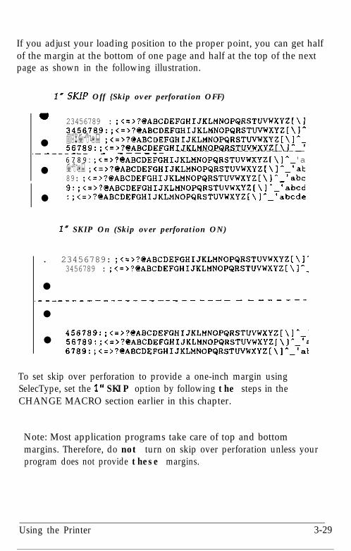
If you adjust your loading position to the proper point, you can get halfof the margin at the bottom of one page and half at the top of the nextpage as shown in the following illustration.
I” SUP Off {Skip over perforation OFF)
I 23456789 : ;<=>?@ABCDEFGHIJKLMNOPQRSTUVWXYZ[\I3456789:;<=~?@ABCDEFGHIJKLMNOPQRSTUVWXYZ~\~~
l 456789: ;<=>?@ABCDEFGHIJKLMNOPQRSTUVwXYZ[\l~m56789:;<=>?@ABCDEFGHIJKLMNOPQRSTUVWXYZ[\~'--',________ - ----_- -----------------------6 7 8 9 : ;<=>?@ABCDEFGHIJKLMNOPQRSTUVWXYZ[\I^ 'a
l 789: ;<=>?@ABCDEFGHIJKLMNOPQRSTUVWXYZ[\II-at89: ;<=>?@ABCDEFGHIJKLMNOPQRSTUVWXYZ[\j'_'abC9:;<=>?@ABCDEFGHIJKLMNOPQRSTUVWXYZ[\]*-'abed
l :;<=>?@ABCDEFGHIJKLMNOPQRSTUVWXYZ[\l^_'abcde
IN SKIP On (Skip over perforation ON)
. 23456789: ;<=>?@'ABCDEFGHIJKLMNOPQRSTUVWXYZ[\]'3456789 : ;<=>?@ABCDEFGHIJKLMNOPQRSTUVWXYZ[\]--
l.--------------------- __-_-_------
l
456789:;<=>?@ABCDEFGHIJKLMNOPQRSTUVWXYZ[\]--'l 56789:;<=>?@ABCDEFGHIJKLMNOPQRSTUVWXYZ[\]* 't
6789:;<=>?@ABCDEFGHIJKLMNOPQRSTUVWXYZ[\IA-'at
To set skip over perforation to provide a one-inch margin usingSelecType, set the 1” SKIP option by following the steps in theCHANGE MACRO section earlier in this chapter.
Note: Most application programs take care of top and bottommargins. Therefore, do not turn on skip over perforation unless yourprogram does not provide these margins.
Using the Printer 3-29

Setting the Loading PositionThe loading position is the position of the paper when it has beenautomatically loaded by the printer.
The loading position is important because it determines where theprinting begins on each page. If the printing is too high or too low on thepage, change the loading position using the micro-adjustment featuredescribed below.
Separate loading positions can be set for single sheets, continuous paper,and sheets loaded by the cut sheet feeder.
v1.
WARNING: Never use the platen knob for feeding exceptin the case of a paper jam or other paper feed problem.Using the platen knob while the printer is on results in anerror message (ERKG? 12 ). To clear this error, you mustturn off the printer, remove the paper, turn the printerback on, and reload the paper with the LOAD/EJECT button.To adjust the loading position always use the micro-adjustment feature.
Until this loading position is reset, the printer remembers this loadingposition and uses it as a reference point for feeding the paper.
The micro-adjustment feature moves the paper l/180th of an inch at atime to make fine adjustments of the loading position. Once you haveused micro-adjustment to change the loading position of continuouspaper, the printer remembers that position even after you turn off orinitialize the printer. However, the printer does not remember the loadingposition for friction or cut sheet feeder mode.
Adjusting the loading positionTo adjust the loading position, follow these steps:
1. Load your paper.
2. Press the MICRO FEED button to select the micro-feed mode. TheMICRO FEED light comes on and the display shows TOF ADJLIST. (TOFstands for top of form.)
3-30 Using the Printer

3. Press the FORM FEED (A) button to feed the paper forward or theLINE FEED (V ) button to feed the paper backward.
Note: The printer beeps when the paper reaches a position that isapproximately l/3 of an inch from the top edge of the paper. Youcan use this position as a reference point when you adjust theprinter’s loading position.
4. Once you have adjusted your paper, press the MICRO FEED buttonagain to turn off this feature.
Short Tear-OffThere are two ways of operating the short tear-off feature. The easierway is to set the AUTO TEAR OFF option with SelecType. When you havefinished printing and if the perforation is at the top of form position, theprinter automatically feeds the perforation of the continuous paper to thetear-off edge of the paper guide cover so you can tear off the last printedsheet. When you resume printing, the paper automatically feeds back tothe loading position. See the CHANGE MACRO section in this chapterfor instructions on setting the fYJT0 TEAR DFF option.
The other way to operate the short tear-off feature is by using the TEAROFF button on the control panel to feed the perforation of your
Using the Printer 3-31
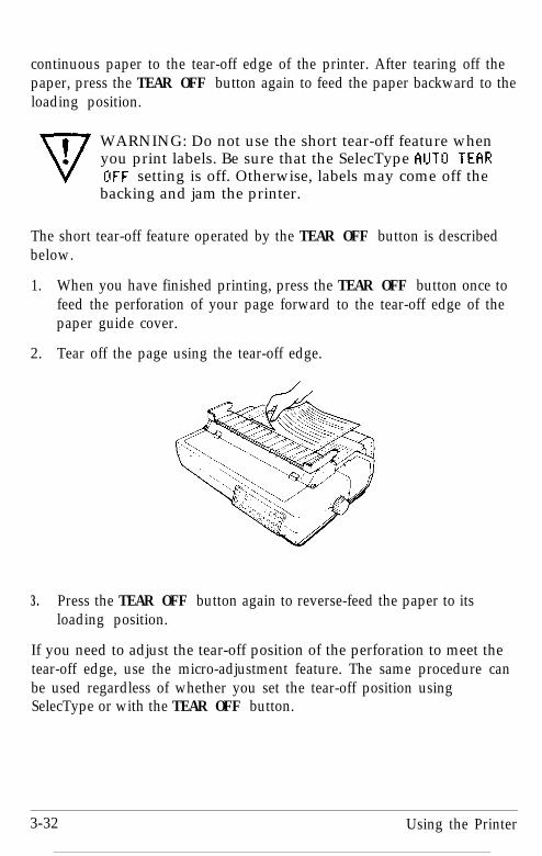
continuous paper to the tear-off edge of the printer. After tearing off thepaper, press the TEAR OFF button again to feed the paper backward to theloading position.
WARNING: Do not use the short tear-off feature whenyou print labels. Be sure that the SelecType AUTO TECIROFF setting is off. Otherwise, labels may come off thebacking and jam the printer.
The short tear-off feature operated by the TEAR OFF button is describedbelow.
1. When you have finished printing, press the TEAR OFF button once tofeed the perforation of your page forward to the tear-off edge of thepaper guide cover.
2. Tear off the page using the tear-off edge.
3. Press the TEAR OFF button again to reverse-feed the paper to itsloading position.
If you need to adjust the tear-off position of the perforation to meet thetear-off edge, use the micro-adjustment feature. The same procedure canbe used regardless of whether you set the tear-off position usingSelecType or with the TEAR OFF button.
3-32 Using the Printer

First, make sure that the TEAR OFF light is on, and then press the MICROFEED button. The display shows TEf!R OFF f3DJUST. Next, adjust thetear-off position in 1080th of an inch increments by pressing the FORMFEED button (A) to feed the paper forward or the LINE FEED button (V)to feed it backward. After setting the position, press the MICRO FEEDbutton again.
TEAROFF
c I
Caution: The short tear-off feature can only be used with the built-intractor feeding system.
Once you use the micro-adjustment feature to set the tear-off position,the printer remembers that position even after it is turned off.
Selecting TypestylesYour printer can produce a wide range of typestyles by using differentfonts, pitches, widths, and other print variations. You can selecttypestyles in three different ways: by using software commands, by usingSelecType, or by using other features available on the control panel. Thissection describes how to select a typestyle using the FONT, PITCH, andCONDENSED buttons on the control panel.
Using the Printer 3-33

The settings you select using the control panel do not remain validonce the printer is turned off. Also, commands from yourapplication program temporarily override these control panelsettings.
Fonts
Your printer has eight built-in fonts and, with the optional Multi-Font Module, two additional fonts are available. To select a font,hold down the FONT button until the display shows the desired font.
The following samples show the character set available for eachfont.
ROMAN
!“#$%&‘( I*+,-./0123456789:;<=>?@ABCDEFGHIJKLMNOPQRSTUVWXYZ(\]^-‘abcdefghijklmnopqrstuvwxyz(l }‘C~~~~BBc~~P~iiffBB~~~~~~~l~~~~~~~~~~~Lifif4~QjrT** i <<>>
W e ’ v e j u s t s e e n y o u r e x c e l l e n t a d f o rminiature zebras i n a r e c e n t b a c k i s s u e o fT r a d e r ’ s T i m e s .
3-34 Using the Printer

SANS SERIF
W e ’ v e j u s t s e e n y o u r e x c e l l e n t a d f o rm i n i a t u r e z e b r a s i n a r e c e n t b a c k i s s u e o fTrader’s T imes .
COURIER
We've just seen your excellent ad forminiature zebras in a recent back issue ofTrader's Times.
PRESTIGE
!"#$%&'()*+,-./0123456789:;<=>?@ABCDEFGHIJKLMNOPQRSTUVWXYZ[\]^-‘abcdefghijklmnopqrstuvn . . . . . L \ . .
We've just seen your excellent ad forminiature zebras in a recent back issue ofTrader's Times.
SCRIPT
W e ’ v e jti* been YOU exc&eti a d hoa. .
~IUU&U&Q zebluLa i n a Jtecen-t b a c k -Caaue 04TJUI.&X’~ Time&.
Using the Printer 3-35

OCR-B
We've just seen your excellent ad forminiature zebras in a recent back issue ofTrader's Times.
OCR-A
We've just seen your excellent ad forminiature zebras in a recent back issue ofTrader's Times.
ORATOR!"#a&'()*+,- . /Ql234$6789: ; <=>?AABCDEFGHIJKLMNO~Q~ST~‘&(~~ @,,,&I~&YZEUE FUEAAAACEEEIIIA ii!
EF~~~#$~MNOPQRS~&!~IEROOOUUYOU$EW~AIO
UNNSQ&rl~$iO
WE'VE JUST SEEN YOUR EXCELLENT AD FORMINIATURE ZEBRAS IN A RECENT BACK ISSUE OFTRADER'S TIMES.
ORATOR-S! “#§%&‘( >*+,- ./Q12j456789:;<=)?tiABCDEFGHIJKLMNO?@STUWg @,,,gt!bpgzeue $ueaaaaCeeeillA iii!
efg~~~~~moopsrsf~~
unNPQ&rl~~itl&ooouuyOU$EVkfaio
We've just seen your excellent ad forminiature zebras in a recent back issue ofTrader’s Times.
3-36 Using the Printer

Draft mode uses fewer dots per character for high-speed printing,which makes it ideal for rough drafts.
The other fonts are printed in Letter Quality (LQ) mode. LetterQuality fonts take a little longer to print, but produce fully formedcharacters for presentation-quality documents.
Pitch
For most of the eight built-in fonts, you can choose a fixed characterpitch of 10, 12, or 15 characters per inch (CPI), or proportionalspacing.
To select a pitch, hold down the PITCH button until the displayshows the desired pitch.
PITCHL-JSome of the fonts do not offer all pitches. See the table below.
Draft 10, 12, 15Roman 10, 12, 15, ProportionalSans Serif 10, 12, 15, ProportionalCourier 10, 12, 15, ProportionalPrestige 10, 12, 15, ProportionalScript 10, 12, 15, ProportionalOCR-A 10, 12, ProportionalOCR-B 10, 12, ProportionalORATOR (Optional)10ORATOR-S (Optional)10
Use Roman or Sans Serif for the best proportional spacing.
Using the Printer 3-37

The following printout compares the fixed pitch settings.
This is 10 pitch printing.This is 12 pitch printing.This is 15 pitch printing.
For the fixed pitch settings (10, 12, and 15 CPI), each character is givenan equal amount of space. For proportional spacing, character widthvaries from one character to the next. For example, a narrow letter like ireceives less space than a wide letter like W. Proportional pitch producestext that is easier to read.
The following printout compares a fixed pitch (10 CPI) spacing withproportional spacing.
This is 10 pitch printing.This is proportional spacing.
Condensed mode
In addition to the three fixed pitches and proportional spacing, you canuse the condensed mode to change the character size. In condensedmode, characters are approximately 60% of the width of normalcharacters. Thus, it is very useful for spreadsheets and other applicationswhere you need to print the maximum amount of information on a page.The 10 CPI, 12 CPI, and Proportional pitches can be condensed; 15 CPIcannot be.
3-38 Using the Printer

To select condensed mode, press the CONDENSED button so that thegreen light comes on. To turn off condensed mode, press the buttonagain.cclrnDENSE0 Condensed 10 cpi gives you more characters on a line,
Condensed 12 cpi gives you even more!
Choosing an International Character Set
The capability to select an international character set provides youwith a range of characters and symbols used in other languages. Byusing the SelecType C 0 U NTR Y option, you can select one offourteen international character sets or the Legal characters. See thetable below.
International character sets
CountryASCII code (hex)
23 24 40 58 5C 5D 5E 60 78 7C 7D 7E
0 U.S.A. #$@[\I^1 France : { : I ;
#$B”c§^ &ilG2 Germany
#$~~oU^‘..a..n
3 U.K. ~$@[\I-‘{:)”4 Denmark I # $ e Al 0 A * f Eta ‘0 Q -5 Sweden #!zitiAijA~6~~&ti6 Italy #$e”\~At1216c??i7 Spain I pt $ @ i fi . n 1 ~ fi } -
8 Japan #$@[up-{ I I -9 Norway #nBB0Au6ae0bii
10 Denmark II #$B~0AOf5~0Qii11 Spain II #$Bifiib’iiiCjti12 Latin America #$6iR;kiiifi6ti13 Korea64 Legal
;I;p+Yyl,0 ” n Q @ .f. 111
To select the desired international character set using SelecType, setthe COUNTRY option by following the steps in the CHANGEMACRO section earlier in this chapter.
Using the Printer 3-39
Choosing a Character TableThe SelecType Cci TflBLE setting lets you select the Epson ExtendedGraphics character table, the italics character table, or the downloadcharacter table. (CC stands for Character Generator.)
The Epson Extended Graphics character table contains graphicscharacters (for printing lines, comers, and shaded areas), internationalcharacters, Greek characters, and mathematical symbols.
If you have an IBM® or compatible computer, select the Epson ExtendedGraphics table when you wish to print the graphics characters as theyare displayed on the screen. Since the character table setting affects onlythe upper half of the character table, you can still print text if you haveselected the Epson Extended Graphics table.
Note: See Appendix B for more information on character tables.
To re-map any downloaded characters from the positions O-127 to thepositions 128-255, select the download character table. (See Chapter 4for more information on user-defined characters.)
Selecting the italics table defines the upper half of the character table asitalic characters. However, you can print italics even if you choose theEpson Extended Graphics character set, simply by using the ESC 4command. (See Chapter 8.) If your application program prints graphicscharacters when you select italic characters, switch to the italic charactertable.
If you select the Epson Extended Graphics character set, you might needto choose a different printer from your program’s printer installationroutine (see Chapter 4). Your first choice should still be the LQ-2550 andyour second choice the LQ-2500. Your third choice should be theLQ-800/1000 printer equipped with the ESC/P identity module. Thesecond and third choices give you the same character and command setfound on the LQ-2550.
If none of these printers is listed, you should contact the program’smanufacturer to find out whether an update is available.
3-40 Using the Printer
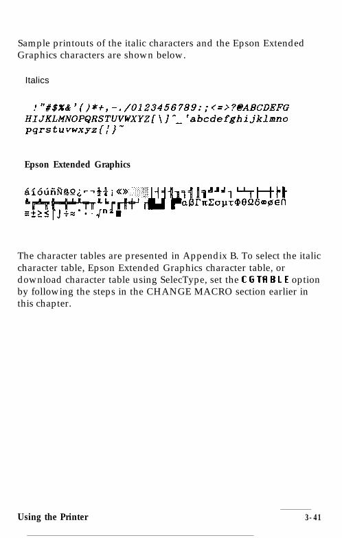
Sample printouts of the italic characters and the Epson ExtendedGraphics characters are shown below.
Italics
!"%$%&'()*i,-./0123456789:;(=,?01ABCDEFGHIJKLMNOPQRSTUVWXYZ[\]*~'abcdefghijklmnopqrstuvwxyz{~}"
Epson Extended Graphics
The character tables are presented in Appendix B. To select the italiccharacter table, Epson Extended Graphics character table, ordownload character table using SelecType, set the C G TB B L E optionby following the steps in the CHANGE MACRO section earlier inthis chapter.
Using the Printer 3-41
Chapter 4Using Software and GraphicsUsing the LQ-2550 with Application Programs . . . . . . . . . . . . . . . . . 4-2
Using printer selection menus . . . . . . . . . . . . . . . . . . . . . . . . . . . . . 4-2A quick test. . . . . . . . . . . . . . . . . . . . . . . . . . . . . . . . . . . . . . . . . . . . . 4-2Using word processors . . . . . . . . . . . . . . . . . . . . . . . . . . . . . . . . . . . 4-3Using spreadsheets . . . . . . . . . . . . . . . . . . . . . . . . . . . . . . . . . . . . . . 4-3Using graphics software. . . . . . . . . . . . . . . . . . . . . . . . . . . . . . . . . . 4-4
Computer-Printer Communication . . . . . . . . . . . . . . . . . . . . . . . . . . . 4-5Escape sequences . . . . . . . . . . . . . . . . . . . . . . . . . . . . . . . . . . . . . . . 4-6Printer commands. . . . . . . . . . . . . . . . . . . . . . . . . . . . . . . . . . . . . . . 4-6Using the Command Summary . . . . . . . . . . . . . . . . . . . . . . . . . . . . 4-7Sending printer commands . . . . . . . . . . . . . . . . . . . . . . . . . . . . . . . 4-7
Enhancing Your Printing . . . . . . . . . . . . . . . . . . . . . . . . . . . . . . . . . . . 4-7Character size . . . . . . . . . . . . . . . . . . . . . . . . . . . . . . . . . . . . . . . . . . 4-8Special effects and emphasis . . . . . . . . . . . . . . . . . . . . . . . . . . . . . . . 4-8Selecting typestyles with Master Select . . . . . . . . . . . . . . . . . . . . 4-11
Graphics . . . . . . . . . . . . . . . . . . . . . . . . . . . . . . . . . . . . . . . . . . . . . . . 4-12The print head.. . . . . . . . . . . . . . . . . . . . . . . . . . . . . . . . . . . . . . . . 4-13Dot patterns . . . . . . . . . . . . . . . . . . . . . . . . . . . . . . . . . . . . . . . . . . . 4-13Color graphics . . . . . . . . . . . . . . . . . . . . . . . . . . . . . . . . . . . . . . . . . 4-14Twenty-four-pin graphics . . . . . . . . . . . . . . . . . . . . . . . . . . . . . . . 4-15Pin labels . . . . . . . . . . . . . . . . . . . . . . . . . . . . . . . . . . . . . . . . . . . . . 4-15The graphics command . . . . . . . . . . . . . . . . . . . . . . . . . . . . . . . . . 4-16Column reservation numbers . . . . . . . . . . . . . . . . . . . . . . . . . . . . 4-17A simple graphics program. . . . . . . . . . . . . . . . . . . . . . . . . . . . . . 4-18Using hand-calculated data to print graphics . . . . . . . . . . . . . . . 4-18Individual graphics option commands . . . . . . . . . . . . . . . . . . . . 4-22The reassi ning command . . . . . . . . . . . . . . . . . . . . . . . . . . . . . . 4-22
User-Defined Characters. . . . . . . . . . . . . . . . . . . . . . . . . . . . . . . . . . 4-23Designing your characters . . . . . . . . . . . . . . . . . . . . . . . . . . . . . . 4-23Designgrids . . . . . . . . . . . . . . . . . . . . . . . . . . . . . . . . . . . . . . . . . . 4-24Defining your characters . . . . . . . . . . . . . . . . . . . . . . . . . . . . . . . . 4-25Data numbers . . . . . . . . . . . . . . . . . . . . . . . . . . . . . . . . . . . . . . . . . 4-26Sending information to your printer . . . . . . . . . . . . . . . . . . . . . . 4-27Printing user-defined characters . . . . . . . . . . . . . . . . . . . . . . . . . 4-29Copying ROM characters to RAM . . . . . . . . . . . . . . . . . . . . . . . . 4-30Letter Quality characters . . . . . . . . . . . . . . . . . . . . . . . . . . . . . . . . 4-30Proportional mode characters . . . . . . . . . . . . . . . . . . . . . . . . . . . 4-31Superscripts and subscripts . . . . . . . . . . . . . . . . . . . . . . . . . . . . . 4-31Mixing print styles . . . . . . . . . . . . . . . . . . . . . . . . . . . . . . . . . . . . . 4-32
Using Software and Graphics 4-1

Using the LQ-2550 with Application ProgramsNow that you’ve set up and tested the printer, you need to start using itwith your application programs.
Most application programs let you specify the type of printer you’reusing so that the program can take full advantage of the printer’sfeatures. Many programs provide an installation or setup procedure thatpresents a list of printers to choose from. If your application programhas a printer selection menu, use the instructions below.
Using printer selection menus
If your software has a printer selection menu, simply choose LQ-2550. Ifthe menu does not list this printer, choose one of the following. They arelisted in order of preference.
LQ-2500LQ-1050 (LQ-850)LQ-1000 (LQ-800)LQ-500LQ-1500
If none of these printers is listed, choose the first one available of thefollowing: LQ, EX, JX, FX, LX, RX, MX, Epson printer, standard printer,draft printer.
If you plan to use color, choose either the LQ-2550 or the LQ-2500.
To use all the features of the LQ-2550, it is best to use a program with theLQ-2550 on its menu. If your program does not list the LQ-2550, contactthe software manufacturer to see if an update is available.
A quick test
After setting up your application program, print a sample document tomake sure the program and the LQ-2550 are communicating properly. Ifthe document doesn’t print correctly, recheck the program’s printerselection and installation procedure. If you’re still having troubleprinting, consult the troubleshooting section in Chapter 6.
4-2 Using Software and Graphics
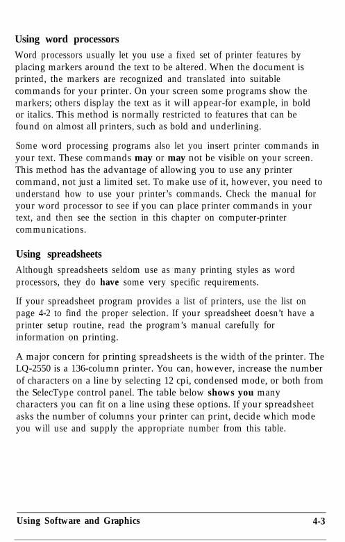
Using word processorsWord processors usually let you use a fixed set of printer features byplacing markers around the text to be altered. When the document isprinted, the markers are recognized and translated into suitablecommands for your printer. On your screen some programs show themarkers; others display the text as it will appear-for example, in boldor italics. This method is normally restricted to features that can befound on almost all printers, such as bold and underlining.
Some word processing programs also let you insert printer commands inyour text. These commands may or may not be visible on your screen.This method has the advantage of allowing you to use any printercommand, not just a limited set. To make use of it, however, you need tounderstand how to use your printer’s commands. Check the manual foryour word processor to see if you can place printer commands in yourtext, and then see the section in this chapter on computer-printercommunications.
Using spreadsheetsAlthough spreadsheets seldom use as many printing styles as wordprocessors, they do have some very specific requirements.
If your spreadsheet program provides a list of printers, use the list onpage 4-2 to find the proper selection. If your spreadsheet doesn’t have aprinter setup routine, read the program’s manual carefully forinformation on printing.
A major concern for printing spreadsheets is the width of the printer. TheLQ-2550 is a 136-column printer. You can, however, increase the numberof characters on a line by selecting 12 cpi, condensed mode, or both fromthe SelecType control panel. The table below shows you manycharacters you can fit on a line using these options. If your spreadsheetasks the number of columns your printer can print, decide which modeyou will use and supply the appropriate number from this table.
Using Software and Graphics 4-3

Unlike word processors, spreadsheet programs usually don’t let youchange printer commands within a spreadsheet. Instead, one style ormode of printing is used for the whole spreadsheet. With the LQ-2550,there are two main ways of sending commands to control the printing ofa spreadsheet. The first method is to choose condensed from theSelecType control panel.
For the second method, look in the manual for your spreadsheet to findout how to send printer commands. Then look in the CommandSummary in Chapter 8 to find the proper codes to send.
For example, your spreadsheet might use a “setup string” to send printercommands. To prepare a setup string for 12 cpi condensed, you wouldlook up the proper command in the Command Summary. The commandfor 12 cpi is ESC M, and the command for condensed is SI. Because mostspreadsheets use the decimal equivalent for the commands, (also given inthe Command Summary), a setup string for 12 cpi condensed might looklike this:
/027/077/015
The number 027 is for the escape code, 077 is for M, and 015 is for SI(condensed).
Using graphics software
The LQ-2550 is capable of producing finely detailed graphic images.Although the section on graphics later in this chapter gives specificinformation on the graphics commands, the easiest way to take advantageof the LQ-2550’s capabilities is with one of the many graphics programsavailable.
4-4 Using Software and Graphics

When buying graphics software, always make sure the program has anoption to print on an LQ printer. Any program with an option for an LQprinter should give excellent results, using different dot densities toproduce a realistic scale of grays.
If you plan to use color, be sure that the program supports color for anLQ printer.
Most graphics programs have a printer selection procedure, in whichcase you should check the lists on page 4-2 to find the proper selection.
Computer-Printer CommunicationYour computer communicates with your printer using a standardized setof numbered codes called ASCII codes (American Standard Code forInformation Interchange). When you press the letter A on the keyboard,it is translated into the ASCII code for A, transmitted to a peripheraldevice such as your computer screen or your printer, and then convertedback into the letter A.
There are ASCII codes for all the letters in the alphabet, both uppercaseand lowercase letters, and for the numbers 0 through 9. The ASCII set ofcodes also includes most punctuation marks and some codes that controlprinter functions.
In the Command Summary in Chapter 8, each code is expressed threedifferent ways: as an ASCII character, as a decimal number, and as ahexadecimal (base 16) number. For example, the uppercase letter A isrepresented as the ASCII character A, the decimal number 65, and thehexadecimal number 41. The numbering system you use depends onyour software and your preferences.
All letters, numbers, and punctuation marks are assigned decimalnumbers from 32 through 255. ASCII codes with decimal values of lessthan 32 are called control codes, because they control the operation ofyour printer and other peripherals. These ASCII characters do notusually have corresponding keys on the keyboard and cannot be printedas characters by your printer.
Using Software and Graphics 4-5

Escape sequences
Although there are more than 30 control codes available to control theoperation of your printer, many more codes are required to run today’ssophisticated printers. Therefore, ASCII codes are grouped in sequencesto represent certain functions. These code sequences use the ASCII codeswith decimal values of 32 through 255, normally reserved for charactersand punctuation, to control printer functions. This is done by firstsending a standard code to tell the printer that the codes that follow areto be used as control codes, not as characters or punctuation.
The standard code that is sent at the beginning of one of these codesequences is the Escape code, decimal value 27. Any sequence of codesstarting with the Escape code is called an Escape sequence. You willprobably see Escape written in different ways-such as ESC, Esc, andEscape-in various manuals. In this manual it is in the form of ESCwhen used within a command.
Printer commands
In order for the printer to recognize the instructions it receives, ASCIIcodes must be sent in a specific format, called a command. An Escapesequence is a command, as is any ASCII code or sequence of codes thatinstructs the printer to carry out a particular function. Your softwarecontinually sends commands to your printer and your computer screen.These commands instruct the printer to perform such actions as print ina particular typeface, feed the paper a certain amount after printing eachline, and start printing on a particular spot on the page.
Some software programs let you send these commands yourself. This is apowerful feature because it allows you to enhance your text in ways thatmay not normally be available through the software. For example, manyword processing programs do not offer italics. By inserting a commandin your document, however, you can use italics anywhere you like. Thecommands that your printer recognizes are listed in the CommandSummary in Chapter 8 and on the Quick Reference card at the back ofthis manual.
4-6 Using Software and Graphics
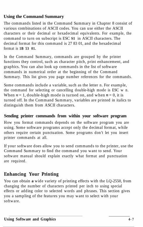
Using the Command Summary
The commands listed in the Command Summary in Chapter 8 consist ofvarious combinations of ASCII codes. You can use either the ASCIIcharacters or their decimal or hexadecimal equivalents. For example, thecommand to turn on subscript is ESC S1 in ASCII characters. Thedecimal format for this command is 27 83 01, and the hexadecimalformat is 1B 53 01.
In the Command Summary, commands are grouped by the printerfunctions they control, such as character pitch, print enhancement, andgraphics. You can also look up commands in the list of softwarecommands in numerical order at the beginning of the CommandSummary. This list gives you page number references for the commands.
Some commands include a variable, such as the letter n. For example,the command for selecting or cancelling double-high mode is ESC w n.When n = 1, double-high mode is turned on, and when n = 0, it isturned off. In the Command Summary, variables are printed in italics todistinguish them from ASCII characters.
Sending printer commands from within your software programHow you format commands depends on the software program you areusing. Some software programs accept only the decimal format, whileothers require certain punctuation. Some programs don’t let you insertprinter commands at all.
If your software does allow you to send commands to the printer, use theCommand Summary to find the command you want to send. Yoursoftware manual should explain exactly what format and punctuationare required.
Enhancing Your PrintingYou can obtain a wide variety of printing effects with the LQ-2550, fromchanging the number of characters printed per inch to using specialeffects or adding color to selected words and phrases. This section givesyou a sampling of the features you may want to select with yoursoftware.
Using Software and Graphics 4-7
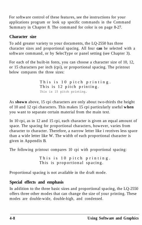
For software control of these features, see the instructions for yourapplications program or look up specific commands in the CommandSummary in Chapter 8. The command for color is on page 8-27.
Character size
To add greater variety to your documents, the LQ-2550 has threecharacter sizes and proportional spacing. All four can be selected with asoftware command, or by SelecType or panel setting (see Chapter 3).
For each of the built-in fonts, you can choose a character size of 10, 12,or 15 characters per inch (cpi), or proportional spacing. The printoutbelow compares the three sizes:
T h i s i s 1 0 p i t c h p r i n t i n g .This i s 12 pi tch pr int ing.This is 15 pitch printing.
As shown above, 15 cpi characters are only about two-thirds the heightof 10 and 12 cpi characters. This makes 15 cpi particularly useful whenyou want to separate certain material from the main text.
In 10 cpi, as in 12 and 15 cpi, each character is given an equal amount ofspace. The spacing for proportional characters, however, varies fromcharacter to character. Therefore, a narrow letter like i receives less spacethan a wide letter like W. The width of each proportional character isgiven in Appendix B.
The following printout compares 10 cpi with proportional spacing:
T h i s i s 1 0 p i t c h p r i n t i n g .This is proportional spacing.
Proportional spacing is not available in the draft mode.
Special effects and emphasisIn addition to the three basic sizes and proportional spacing, the LQ-2550offers three other modes that can change the size of your printing. Thesemodes are double-wide, double-high, and condensed.
4-8 Using Software and Graphics
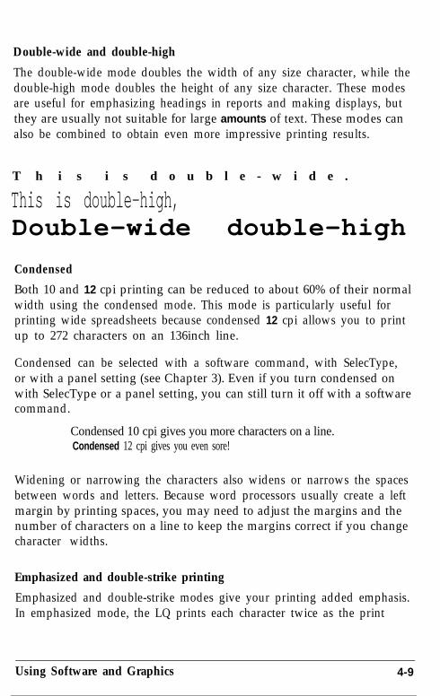
Double-wide and double-high
The double-wide mode doubles the width of any size character, while thedouble-high mode doubles the height of any size character. These modesare useful for emphasizing headings in reports and making displays, butthey are usually not suitable for large amounts of text. These modes canalso be combined to obtain even more impressive printing results.
T h i s i s d o u b l e - w i d e .
This is double-high,Double-wide double-high
Condensed
Both 10 and 12 cpi printing can be reduced to about 60% of their normalwidth using the condensed mode. This mode is particularly useful forprinting wide spreadsheets because condensed 12 cpi allows you to printup to 272 characters on an 136inch line.
Condensed can be selected with a software command, with SelecType,or with a panel setting (see Chapter 3). Even if you turn condensed onwith SelecType or a panel setting, you can still turn it off with a softwarecommand.
Condensed 10 cpi gives you more characters on a line.Condensed 12 cpi gives you even sore!
Widening or narrowing the characters also widens or narrows the spacesbetween words and letters. Because word processors usually create a leftmargin by printing spaces, you may need to adjust the margins and thenumber of characters on a line to keep the margins correct if you changecharacter widths.
Emphasized and double-strike printing
Emphasized and double-strike modes give your printing added emphasis.In emphasized mode, the LQ prints each character twice as the print
Using Software and Graphics 4-9
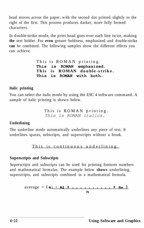
head moves across the paper, with the second dot printed slightly to theright of the first. This process produces darker, more fully formedcharacters.
In double-strike mode, the print head goes over each line twice, makingthe text bolder. For even greater boldness, emphasized and double-strikecan be combined. The following samples show the different effects youcan achieve.
T h i s i s R O M A N p r i n t i n g .This is ROMAN emphasized.This is ROMAN double-strike.This is ROMAN with both.
Italic printing
You can select the italic mode by using the ESC 4 software command. Asample of italic printing is shown below.
T h i s i s R O M A N p r i n t i n g .This is ROMAN italics.
Underlining
The underline mode automatically underlines any piece of text. Itunderlines spaces, subscripts, and superscripts without a break.
T h i s i s c o n t i n u o u s u n d e r l i n i n g .
Superscripts and Subscripts
Superscripts and subscripts can be used for printing footnote numbersand mathematical formulas. The example below shows underlining,superscripts, and subscripts combined in a mathematical formula.
average = (ai + a2 t . . . . . . . . . . t an )n
4-10 Using Software and Graphics

Outline and shadow
The outline and shadow features are useful for adding variation andemphasis to text that you wish to stand out, such as headings. Thefollowing ‘samples show the shadow and outline featuresindividually, and a combination of outline with shadow.
Overscore, strike-through, and underlining
The overscore, strike-through, and underlining modes are useful forhighlighting text. This feature can be used to score spaces,subscripts, and superscripts without a break. You can choose froma variety of line styles: single, double, broken, or continuous. Seethe ESC (- command in Chapter 8 for more information.
T h i s i s c o n t i n u o u s u n d e r l i n i n g ,
Selecting typestyles with Master Select
Your printer has a special ESCape code called Master Select thatallows you to choose combinations of these nine modes: 10 cpi, 12cpi, proportional, condensed, emphasized, double-strike, double-wide, italics, and underline. For more information on sendingESCape codes to your printer, see the section on computer-printercommunication earlier in this chapter.
The format of the Master Select code is shown below:
ASCII: ESC ! nDecimal: 27 33 nHexadecimal: 1B 21 n
The variable n is a number that identifies the mode or combinationof modes. To find the value of n, use the following table to add upeither the decimal or hexadecimal numbers for the features youwant.
Using Software and Graphics 4-11

Feature Dec.10 cpi 0
Hex.00
12 cpi 1 01
proportional 2 02
condensed 4 04
emphasized 8 08
double-strike 16 10
double-wide 32 20
italics 64 40
underline 128 80
For example, to print a title, you may want to use double-wide 12cpi characters and print them in double-strike mode. You add threenumbers together to calculate the value of IZ:
12 cpi 1D o u b l e - s t r i k e 1 6Double-wide 32
n = 49
After calculating the value of IZ, you use the Master Select commandto send the value to the printer.
ASCII: ESC ! 1Decimal: 27 33 49Hexadecimal: 1B 21 31
The print quality and font must be set separately, either usingSelecType or the ESC x and ESC k commands. There are two morethings to consider when using the Master Select command:
l Master Select cancels any of the listed features that you do nottry to set. For example, if you have already set a character sizeother than 10 cpi and you use Master Select to set emphasizeddouble-strike, the character width is reset to 10 cpi.
l Proportional overrides 10, 12, and 15 cpi.
Using Software and Graphics

Graphics
The dot graphics mode allows your printer to produce pictures,graphs, charts, or almost any other graphics. Because manycommercial software programs use graphics, you may be able toprint pictures or graphs like the following one simply by givingyour software a few instructions.
I n c o m e B r e a k d o w n
Salar ies anP r o d u c t i o n
D e v e l o p m e n t
The quickest and easiest way to print graphics is to use acommercial graphics program. With such programs you usuallycreate an image on your monitor and then use a command to sendthe image to the printer.
If you use commercial software that produces graphics, all you needto know about dot graphics is how to use the software. If, on theother hand, you wish to do your own programming or merely wishto understand how the printer prints graphics, read on.
The print head
To understand dot graphics you need to know a little about howyour printer’s print head works. The print head has 24 pins. As theprint head moves across the page, electrical impulses cause the pinsto fire. Each time a pin fires, it strikes the inked ribbon and presses itagainst the paper to produce a small dot. As the head moves acrossthe paper, the pins fire time after time in different patterns toproduce letters, numbers, or symbols.
Using Software and Graphics 4-13

Because the dots overlap each other both horizontally and verticallyin the Letter Quality mode, it is difficult to see individual dots.Instead, the letters and symbols seem to be made of unbroken lines.
In order for the dots to overlap vertically, the pins are in more thanone column, but the intelligence of the printer handles the timing ofpin firings so that the effect is of 24 pins arranged in a single verticalcolumn.
Dot patterns
Your printer’s print head is able to print graphics as well as textbecause graphic images are formed on the printer about the sameway that pictures in newspapers and magazines are printed. If youlook closely at a newspaper photograph, you can see that it is madeup of many small dots. Your printer also forms its images withpatterns of dots, as many as 360 dot positions per inch horizontallyand 360 dots vertically. The images printed by the printer can,therefore, be as finely detailed as the ones at the beginning of thissection.
Color graphics
With the color ribbon and appropriate software, you can print in awide variety of colors. Even if your software doesn’t support color,printer command ESC r lets you select from seven basic colors,including black. In addition, you can combine some of the basiccolors for a greater variety.
4-14 Using Software and Graphics

Twenty-four-pin graphics
The graphics mode that takes full advantage of the printer’s print head is24-pin graphics. This mode has five densities, but for simplicity thisexplanation begins with triple-density.
Triple-density prints up to 180 dots per inch horizontally. As the printhead moves across the paper, it must receive instructions every l/180thof an inch about which of its 24 pins to fire. At each position it can fireany number of pins from none to 24. This means that the printer mustreceive 24 bits of information for each column it prints. Since the printeruses B-bit bytes of information in its communication with the computer,it needs three bytes of information for each position.
Pin labels
To tell the printer which pins to fire in each column, you first divide eachof the vertical columns into three sections of eight pins each and considereach section separately. Since there are 256 possible combinations of theeight pins in each section, you need a numbering system that allows youto use a single number to specify which of the 256 possible patterns youwant. This numbering system is shown below:
128
iii16
:21
To fire any one pin, you send its number. To fire more than one pin atthe same time, you add up the numbers of the pins and send the sum tothe printer. Using these labels for the pins, you fire the top pin bysending 128. To fire the bottom pin, you send 1. If you want to fire onlythe top and bottom pins, you simply add 128 and 1, and send 129.
By adding the appropriate label numbers together, you can fire anycombination of pins. The following three examples show you how tocalculate the number that will fire a particular pattern of pins.
Using Software and Graphics 4-15

With this numbering system, every combination of the eight pins addsup to a decimal number between 0 and 255, and no numbers areduplicated.
Since there are 24 pins in each column, you must make a calculation foreach of the three sections in each column. As you can see, this method ofplanning and printing dot graphics requires considerable calculation.Because triple-density uses 180 columns per inch, printing a single line oftriple-density graphics only one inch long requires 540 numbers.Fortunately, commercial software can do the calculations for you.
Before you can put these numbers in a graphics program, you need toknow the format of the graphics command.
The graphics commandThe graphics mode command is quite different from the other commandsused by the printer. For most of the other printer modes, such asemphasized and double-wide, one ESCape code turns the mode on andanother turns it off. For graphics, the command is more complicatedbecause the code that turns on a graphics mode also specifies how manycolumns it will use. After the printer receives this code, it interprets thenext numbers as pin patterns and prints them on the paper.
Your printer has one command that allows you to use any of the 11graphics options. The format of the command is:
ESC * m n7 n2 data
In this command, m selects the graphics option and nl and YL? specify thenumber of columns to reserve for graphics. The available graphicsoptions are listed in the following table.
4-16 Using Software and Graphics
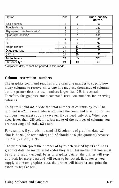
Option Pins m Horizdtiz;;sity
Single-density 8 0 60Double-density 8 1 120High-speed double-density* 8 2 120Quadruple-density* 8 3 240CRT I a 4 80
pi
* Adjacent dots cannot be printed in this mode.
Column reservation numbers
The graphics command requires more than one number to specify howmany columns to reserve, since one line may use thousands of columnsbut the printer does not use numbers larger than 255 in decimal.Therefore, the graphics mode command uses two numbers for reservingcolumns.
To figure nl and n2, divide the total number of columns by 256. Thequotient is rr.2; the remainder is nl. Since the command is set up for twonumbers, you must supply two even if you need only one. When youneed fewer than 256 columns, just make nl the number of columns youare reserving and make n2 a zero.
For example, if you wish to send 1632 columns of graphics data, nlshould be 96 (the remainder) and rr.2 should be 6 (the quotient) because1632 = (6 x 256) + 96.
The printer interprets the number of bytes determined by nl and rr2 asgraphics data, no matter what codes they are. This means that you mustbe sure to supply enough bytes of graphics data or the printer will stopand wait for more data and will seem to be locked. If, however, yousupply too much graphics data, the printer will interpret and print theexcess as regular text.
Using Software and Graphics 4-17

A simple graphics program
This first program is just a simple example to show you how the graphicscommand, column reservation numbers, and data can be used in aBASIC program.
Type and run the following program. Be especially careful to includeboth semicolons. The program produces the printout you see below it.
18 WIDTH "LPT::", 2552@ LPRINT CHR$(27)"*"CHR$(32)CHR$(+I)CHR$(@);3@ FOR X=1 TO 12p49 LPRINT CHR$(17@);50 NEXT X
Line 20 selects single-density 24-pin graphics mode (mode 32) and alsoreserves 40 columns for graphics. Since the 24-pin graphics moderequires three bytes of data for each column, line 30 begins a loop tosupply 120 bytes of data. Line 40 contains the number 170, whichproduces the first pin pattern shown in the section on pin labels, and line50 finishes the loop.
Using hand-calculated data to print graphics
With what you know now, you can use the simplest application ofgraphics-using hand-calculated data to print graphic images. While thismethod is tedious, it helps you understand dot graphics. Also, it is usefulfor small graphic elements that are used many times.
The following illustration shows how you can use a grid to plan whereyou want dots to be printed. This grid is for a single line of graphics 42columns long. Since each line of 24-pin graphics is approximately l/8thof an inch high and since triple-density graphics prints 180 dots per inchhorizontally, a design planned on this grid will be about l/8th of an inchhigh and less than l/4th of an inch wide.
4-18 Using Software and Graphics

The actual pattern that the printer prints on the paper is made up of dotsthat overlap each other both vertically and horizontally. The reason theplanning grid uses an x for each dot is that using an accuraterepresentation of the dots makes calculating the data numbers difficultbecause they cover each other. Therefore, remember that each xrepresents the center of a dot, and the dots actually overlap.
Write the assigned values of the pins next to your design and then totalthe values for each column of dots. These totals are the values that willbe sent to the printer as graphics data.
The following figure is the same grid divided into three sections to makethe data calculation easier. At the bottom of each section of each columnis the total of the pin numbers for that section. This gives you a total of126 data numbers necessary to print this small figure.
Using Software and Graphics 4-19
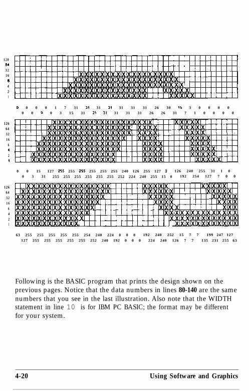
1206432166421
Cl 0 0 0 1 7 31 31 31 3, 31 31 31 26 30 15 3 0 0 0 00 0 0 0 3 15 31 31 31 31 31 31 26 26 31 7 1 0 0 0 0
1266432166421
0 0 15 127 255 255 255 255 255 255 240 126 255 127 0 126 240 255 31 1 00 3 31 255 255 255 255 255 255 252 224 240 255 15 0 192 254 127 7 0 0
1266432166421
63 255 255 255 255 255 254 240 224 0 0 0 192 240 252 15 7 7 199 247 127127 255 255 255 255 255 252 240 192 0 0 0 224 240 126 7 7 135 231 255 63
Following is the BASIC program that prints the design shown on theprevious pages. Notice that the data numbers in lines 80-140 are the samenumbers that you see in the last illustration. Also note that the WIDTHstatement in line 10 is for IBM PC BASIC; the format may be differentfor your system.
4-20 Using Software and Graphics

l@ WIDTH "LPT1:",25520 LPRINT CHR$(27)"*"CHR$(39)MR$(~2)C~$(@);30 FOR X=1 TO 12640READN50 LPRINT CHR$(N);60 NEXT X70 LPRINT80 DATA 0,0,63,0,0,127,0,0,255,0,3,255~0~15>255,0~31~25590 DATA 0,127,255,0,255,255,1,255,255,3,255,255,7,255,255~15~
255,255100 DATA 31,255,254,31,255,252,31,255,248,31,255,240,31,255,
224,31,255,192110 DATA 31,255,0,31,252,0,31,240,0,31,224,0,31,12~~0~31~240~0120 DATA 31,255,192,28,255,224,28,127,240,28,15,248,30,0,2521
31,0,126130 DATA 15,128,15,7,192,7,3,2~~,7,1,25~,7,~~255~7~~~~27~135140 DATA 0,31,199,0,7,231,0,1,247,0,0,255~0~0~127t0~0~63
In this program, line 20 assigns the graphics option (24-pin triple-density)with code 39. Code 42 sets the number of pin columns at 42. Lines 80-140 contain 126 bytes of data (42 pin columns x 3 bytes) for each pincolumn. Lines 30-60 print the following design.
Notice that the dots overlap quite a bit. This design was printed using thetriple-density 24-pin graphics option because the density is the same (180dots to the inch) in both directions.
Adding the following lines to the preceding program causes the patternto print 10 times in a row as shown below.
15 FOR C=l TO 10: RESTORE65 NEXT C
Using Software and Graphics 4-21

Individual graphics option commands
There are four individual graphics option commands that are very muchthe same as the ESC * command, but each one works for only onegraphics option. All these commands are for B-pin graphics options.Note that the commands contain one less variable than the ESC *command because they don’t need to select a graphics option.
The commands are shown below:
Because of a difference in line spacing increments, the shape of graphicsfigures produced on the LQ-2550 with an B-pin option is different fromthe output from the same program on a 9-pin printer.
The reassigning command
The LQ-2550 has a command that allows you to change the graphicsoption assigned to any of the four individual graphics option commands.
The command looks like this:
ESC?sm
The letter s represents the command that you wish to change theassignment for (K, L, Y, or Z) and m is the number of the graphicsoption that you want to assign to it. For example, to change the ESC Kcommand to use the CRT I graphics option, the command in BASIC is:
LPRINT CHR$(27) ;"?";"K";CHR$(1,)
This is a quick way to change the aspect ratio of the design that you areprinting. Changing the graphics option will change the width withoutchanging the height. You should, however, make this change withcaution.
4-22 Using Software and Graphics
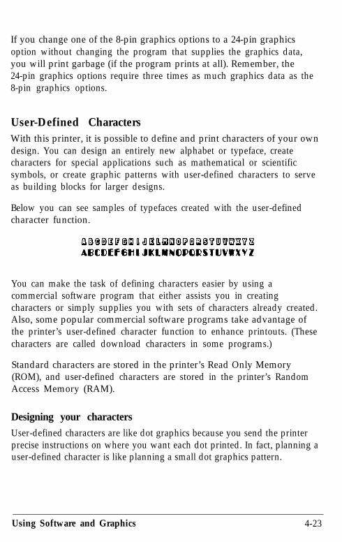
If you change one of the 8-pin graphics options to a 24-pin graphicsoption without changing the program that supplies the graphics data,you will print garbage (if the program prints at all). Remember, the24-pin graphics options require three times as much graphics data as the8-pin graphics options.
User-Defined CharactersWith this printer, it is possible to define and print characters of your owndesign. You can design an entirely new alphabet or typeface, createcharacters for special applications such as mathematical or scientificsymbols, or create graphic patterns with user-defined characters to serveas building blocks for larger designs.
Below you can see samples of typefaces created with the user-definedcharacter function.
You can make the task of defining characters easier by using acommercial software program that either assists you in creatingcharacters or simply supplies you with sets of characters already created.Also, some popular commercial software programs take advantage ofthe printer’s user-defined character function to enhance printouts. (Thesecharacters are called download characters in some programs.)
Standard characters are stored in the printer’s Read Only Memory(ROM), and user-defined characters are stored in the printer’s RandomAccess Memory (RAM).
Designing your characters
User-defined characters are like dot graphics because you send the printerprecise instructions on where you want each dot printed. In fact, planning auser-defined character is like planning a small dot graphics pattern.
Using Software and Graphics 4-23
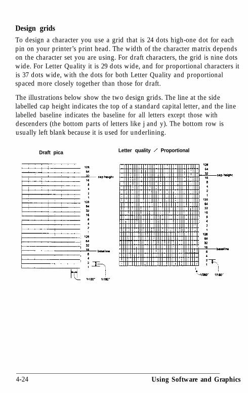
Design grids
To design a character you use a grid that is 24 dots high-one dot for eachpin on your printer’s print head. The width of the character matrix dependson the character set you are using. For draft characters, the grid is nine dotswide. For Letter Quality it is 29 dots wide, and for proportional characters itis 37 dots wide, with the dots for both Letter Quality and proportionalspaced more closely together than those for draft.
The illustrations below show the two design grids. The line at the sidelabelled cap height indicates the top of a standard capital letter, and the linelabelled baseline indicates the baseline for all letters except those withdescenders (the bottom parts of letters like j and y). The bottom row isusually left blank because it is used for underlining.
Draft pica Letter quality / Proportional
4-24 Using Software and Graphics

The second grid can be used for either Letter Quality or proportionalcharacters. For Letter Quality you do not use all the columns.
There is one restriction in designing characters. Dots in the same row do notprint in adjacent columns. That is, there must be an empty dot position tothe left and to the right of each dot that prints. This is true in draft, LetterQuality, and proportional mode.
Defining your characters
The first step in defining characters is to place the dots on a grid just as youwant them to print. The examples here, like the ones in the graphics section,use an x to represent each dot.
In the following illustration, you see a draft grid with a simple user-definedcharacter planned on it.
Using Software and Graphics 4-25

Now you translate the dot pattern you’ve created on paper to a numericformat so you can send the information to your printer. Every dot has anassigned value. Each vertical column (which has a maximum of 24 dots) isfirst divided into three groups of eight dots. Each group of eight dots isrepresented by one byte. Since one byte consists of eight bits, one bitrepresents one dot.
Data numbers
The bits within each byte have values of 1, 2, 4, 8, 16, 32, 64, and 128. Inthe vertical column of dots, the bits are arranged so that the most significantbit (which has a value of 128) is at the top and the least significant bit(which has a value of 1) is at the bottom.
The next illustration shows you how to use this method to calculate thedata numbers for the example character. On the left side of the figure, thedata numbers are calculated for the middle column. The value of each byteis calculated by adding the values of the rows where dots appear. The rightside of the figure shows the whole character with the three data numbers foreach column indicated at the bottom.
This manual uses decimal numbers because the example programs in thismanual are written in BASIC and everyone is familiar with decimals. Thedata you send to your printer, however, can be in any form (binary,decimal, hexadecimal) that you can use with your programming language.
4-26 Using Software and Graphics

Now you’ve seen how to design a character by placing dots on a gridand translating the dots to decimal equivalents. The last step in defininga character is to send this information to the printer.
Sending information to your printer
The printer loads characters in the print style (Letter Quality, draft, orproportional) that the printer is currently using. It also records whetheritalic, superscript, or subscript is turned on. This means that if you wantto print a character in the italic mode, for example, you must have theitalic mode turned on when you define the character.
The command your printer uses to define characters is one of the mostcomplex in its repertoire. The format of the command is this:
ESC & 0 nl n2 do dl d2 data
The ESC & is simple enough. The 0 (which is ASCII code 0, not thenumeral zero in quotation marks) allows for future enhancements. Atthis time, it is always ASCII 0.
With your printer, you can define many characters with a singlecommand. The values nl and n2 are the ASCII codes for the first andlast characters you are defining. If you are defining only one character,nl and n2 are the same. You can use any codes between 0 and 127decimal for nl and n2, but it is best not to define decimal 32, which isthe code for a space. Also, you can use letters in quotation marks insteadof ASCII numbers for nl and n2.
An example will show you how to specify nl and n2. If, for instance,you wanted to redefine the characters A through Z, nl would be A (orASCII code 65) and n2 would be Z (or ASCII code 90). So the commandESC & 0 AZ (followed by the appropriate data) would replace the entirealphabet of capital letters.
Following the specification of the range of characters to be defined in thiscommand are three data bytes (do-&) that specify the width of thecharacter and the space around it. The left space (in dot columns) isspecified by do, and the right space is specified by dz. The second byte(dl) specifies the number of columns of dots that are printed to make up
Using Software and Graphics 4-27

the character. By varying the width of the character itself and the spacesaround it, you can create proportional-width characters that print atdraft speed.
The table below shows the maximum values for these bytes.
The last part of the character definition is the actual data that defines thedot patterns for each character. Since it takes three bytes to specify thedots in one vertical column of dots, your printer expects dl x 3 bytes ofdata to follow dz.
An example character definition program should make this clear:
10 LPRINT CHR$(27)"x0"20 LPRINT CHR$(27)"&"CHR$(0);30 LPRINT "@@";40 LPRINT CHR$(l)CHR$(9)CHR$(l);50 FOR I=1 TO 2760 READ A: LPRINT CHR$(A);70 NEXT I80 LPRINT "@@@@@"90 LPRINT CHR$(27)"%"CHR$(l);100 LPRINT "@@@@@"110 LPRINT CHR$(27)"%"CHR$(0);120 LPRINT "@@@@@"130 END140 DATA 1,0,0,2,0,0,4,0,0150 DATA 8,0,0,23,255,240,8,0,0160 DATA 4,0,0~,0,0,~0,0
In line 10, the ESC x0 command selects draft style printing.
4-28 Using Software and Graphics

The actual character definition starts in line 20. The two at signs (@) inline 30 represent nl and FG!, the range of characters being defined (in thiscase, a range of one). Line 40 contains do, dl, and d2.
The information about the actual character design (which is contained inthe data statements at the end of the program) is sent to the printer in theloop between lines 50 and 70.
Note: When defining Letter Quality or proportional characters inBASIC, put a WIDTH statement in your program to prevent carriagereturn and line feed codes from interfering with your definitions.
Printing user-defined characters
The example program above defines an arrow and places it in the RAMlocation for ASCII code 64 (replacing the @ sign). When you run theprogram, it prints a three-line sample of your work. The first and thirdlines (printed by lines 80 and 120 of the program) print the normal @sign: the second line (line 100) prints the arrow that you defined.
Run the program to see the printout below:
@@@@rOTTTTT
@@@@@
As you can see, both sets of characters (the original ROM characters thatthe printer normally uses and the user-defined character set) remain inthe printer available for your use. The command to switch between thetwo sets is used in line 90 and 110:
ESC % n
If n is 0, the normal ROM character set is selected (this is the default). Ifn is 1, the user-defined character set is selected. If you select the user-defined character set before you have defined any characters, thecommand is ignored and the ROM characters remain in use.
Using Software and Graphics 4-29

You may switch between character sets at any time-even in the middleof a line. To try it, place semicolons at the end of lines 80 and 100 in theprogram above.
Copying ROM characters to RAMAfter running the program above, if you select the user-defined characterset and try to print other characters, the only one that will print is thearrow. Since no other characters are in the printer’s user-defined RAMarea, nothing else prints. Other characters don’t even print as spaces; it’sas if they were not sent at all.
In many cases, you may want to redefine only a few of the characters tosuit your needs; the rest of the alphabet will work fine as it is. As youhave seen, it is possible to switch back and forth between the normalcharacter set and the user-defined character set. It is, however, ratherinconvenient.
To make things easier, your printer has a command that allows you tocopy all of the standard characters from ROM to the user-definedcharacter set.
The command format is as follows, where the value of n represents thefont family:
ESC : 0 n 0
Note: This command cancels any user-defined characters you havecreated. You must send this command to the printer before you definecharacters.
If you use this command at the beginning of a program, then define yourspecial characters and select the user-defined character set, you can printwith the user-defined set as your normal character set. You never need toswitch back and forth between sets.
Letter Quality charactersIf you select Letter Quality printing with the ESC xl command, you candesign user-defined characters using up to 29 columns of the LetterQuality/Proportional grid. The dot columns are spaced closer together
4-30 Using Software and Graphics
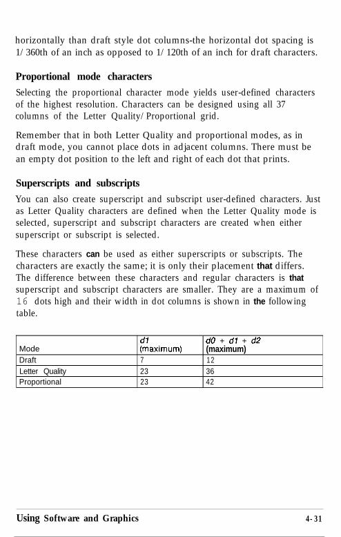
horizontally than draft style dot columns-the horizontal dot spacing is1/360th of an inch as opposed to 1/120th of an inch for draft characters.
Proportional mode characters
Selecting the proportional character mode yields user-defined charactersof the highest resolution. Characters can be designed using all 37columns of the Letter Quality/Proportional grid.
Remember that in both Letter Quality and proportional modes, as indraft mode, you cannot place dots in adjacent columns. There must bean empty dot position to the left and right of each dot that prints.
Superscripts and subscripts
You can also create superscript and subscript user-defined characters. Justas Letter Quality characters are defined when the Letter Quality mode isselected, superscript and subscript characters are created when eithersuperscript or subscript is selected.
These characters can be used as either superscripts or subscripts. Thecharacters are exactly the same; it is only their placement that differs.The difference between these characters and regular characters is thatsuperscript and subscript characters are smaller. They are a maximum of16 dots high and their width in dot columns is shown in the followingtable.
ModeDraftLetter QualityProportional
72323
do + dl + d2(maximum)123642
Using Software and Graphics 4-31

Since these characters are smaller, when you define them you need onlytwo bytes of data for each vertical row of dots. Design grids for thesecharacters are shown in the following figure.
Draft picaLetter Quality
and Proportional
Mixing print styles
Each of the three user-defined character modes (draft, Letter Quality, andproportional) can be used in combination with most of your printer’svarious print styles. For instance, you can use emphasized with youruser-defined characters.
Mixing the three types of user-defined character sets is not permitted. If,for example, you select draft mode and define some characters, thenselect proportional and define some more, the first character definitionsare destroyed. Only one type of character definition may be stored inRAM at any time.
If you define characters in one mode, then switch to another mode andselect the user-defined character set, the command is ignored and nothingis printed. The user-defined character definitions, however, remainunaffected. If you switch back to the mode in which they were defined,you can then select and print them.
4-32 Using Software and Graphics

Keep in mind that user-defined characters are stored in RAM, which isnot permanent. Whenever the printer power is turned off or the printer isinitialized with the INIT signal, the user-defined characters are lost.(Some computers do this each time BASIC is loaded.) ESC @, however,does not destroy user-defined characters.
Using Software and Graphics 4-33
Chapter 5Maintenance and Transportation
Cleaning the Printer . . . . . . . . . . . . . . . . . . . . . . . . . . . . . . . . . . . . . . . . . 5-2
Replacing the Ribbon . . . . . . . . . . . . . . . . . . . . . . . . . . . . . . . . . . . . . . . . 5-3
Transporting the Printer . . . . . . . . . . . . . . . . . . . . . . . . . . . . . . . . . . . . . . 5-7
Maintenance and Transportation 5-1

Cleaning the PrinterTo keep your printer operating at its best, you should clean it thoroughlyseveral times a year.
Follow these steps to clean the printer:
1. Turn off the printer.
2. Remove the paper guide and any installed options.
3. Use a soft brush to carefully clear away all dust and dirt.
4. If the outer case or printer cover is dirty or dusty, clean it with a soft,clean cloth dampened with mild detergent dissolved in water. Keepthe printer cover in place to prevent water from getting inside theprinter.
5-2 Maintenance and Transportation

WARNING:
l Never use alcohols or thinners to clean the printer; these chemi-cals can damage the components as well as the case.
l Be careful not to get water on the printer mechanism or elec-tronic components.
l Do not use a hard or abrasive brush.
l Do not spray the inside of the printer with lubricants; unsuitableoils can damage the mechanism. Contact your Epson dealer ifyou think lubrication is needed.
Replacing the RibbonWhen your printing becomes too faint, you need to replace the ribbon. Thefollowing Epson replacement ribbon cartridges are available:
#7762 : Standard (black)#7763 : Color#7764 : Film (black)
Note: The optional film ribbon prints in red near the end of the ribbon.Replace the film ribbon at this point.
To replace the ribbon follow the procedure below:
1. Turn off the power to the printer and remove the printer cover and thepaper guide cover.
WARNING: If the printer has been used recently, the print headmay be hot. Let it cool before attempting to replace the ribbon.
Maintenance and Transportation 5-3

2. Holding the print head, not the ribbon cartridge, move the printhead to the middle of the printer.
3. To release the ribbon cartridge, gently press the tab at the top of theholder; then lift the cartridge straight up and out of the printer.
5-4 Maintenance and Transportation

4. Turn the ribbon-tightening knob on the ribbon cartridge in thedirection of the arrow.
5. Hold the ribbon cartridge while gently squeezing the two ridgedplastic tabs together; then lower it until it snaps into place. The sidehooks in the printer should fit into the slots on each side of theribbon cartridge.
Maintenance and Transportation 5-5

6. Turn the ribbon tightening knob again to make sure the ribbon
7. Holding the print head, slide the print head from side to side to makesure that it moves smoothly. (Do not try to slide the print head bygrasping the ribbon cartridge.)
5-6 Maintenance and Transportation

Transporting the PrinterIf you need to transport your printer some distance, carefully repack theprinter using the original box and packing materials, as described below.
1. Turn off the printer.
2. Remove any installed options.
3. Remove the printer cover, paper guide, paper guide cover, and cablecover.
4. Unplug the power cable from the electrical outlet; then disconnectthe cable between the printer and the computer.
5. Remove the ribbon cartridge and platen knob.
Maintenance and Transportation 5-7
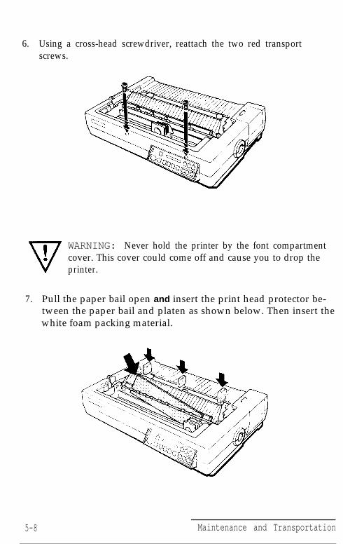
6. Using a cross-head screwdriver, reattach the two red transportscrews.
WARNING: Never hold the printer by the font compartmentcover. This cover could come off and cause you to drop theprinter.
7. Pull the paper bail open and insert the print head protector be-tween the paper bail and platen as shown below. Then insert thewhite foam packing material.
5-8 Maintenance and Transportation

8. Reattach the paper guide cover and printer cover.
Maintenance and Transportation 5-9

Chapter 6Troubleshooting
Problems and Solutions . . . . . . . . . . . . . . . . . . . . . . . . . . . . . . . . . . . . . . 6-2The printer does not print . . . . . . . . . . . . . . . . . . . . . . . . . . . . . . . . . . 6-2The printer stops printing . . . . . . . . . . . . . . . . . . . . . . . . . . . . . . . . . . 6-2The printout is spaced incorrectly . . . . . . . . . . . . . . . . . . . . . . . . . . . . 6-3The printout is faint or uneven . . . . . . . . . . . . . . . . . . . . . . . . . . . . . . 6-3The printout is not what you expect . . . . . . . . . . . . . . . . . . . . . . . . . . 6-3Single sheets do not feed properly . . . . . . . . . . . . . . . . . . . . . . . . . . 6-4Continuous paper does not feed properly . . . . . . . . . . . . . . . . . . . . . 6-4Cut sheet feeder does not load paper correctly . . . . . . . . . . . . . . . . . 6-5The short tear-off feature does not work properly . . . . . . . . . . . . . . 6-5Color printing is not what you expect . . . . . . . . . . . . . . . . . . . . . . . . 6-5
Data Dump Mode . . . . . . . . . . . . . . . . . . . . . . . . . . . . . . . . . . . . . . . . . 6-6
Troubleshooting 6-1

TroubleshootingThis chapter discusses problems you may encounter and their likelysolutions. At the back of the chapter is a section on the data dumpmode. This mode helps more experienced users determine the causes ofcommunication problems between the printer and the computer.
Problems and SolutionsThis section lists possible problems and their likely solutions.
The printer does not print
l Be sure the printer is turned on and the POWER light is on. If theprinter is turned on but the POWER light is not on, check to see thatthe printer is fully plugged in and that the electrical outlet is alsoturned on.
l Be sure the ON LINE light is on. If it is not on, press the ON LINEbutton.
l Be sure the printer is connected securely to the computer. Check bothends of the cable between the printer and the computer.
l Be sure the printer is not out of paper. (The PAPER OUT light shouldbe off .)
l Be sure that all protective materials are removed from the printer.
If the printer still does not print, disconnect the printer from thecomputer and try the self test described in Chapter 1. If the self testworks properly, the printer is working and the problem probably lies inthe computer, the software, or the cable. If the self test does not work,contact your Epson dealer.
The printer stops printing
l The printer may be out of paper. Check the paper supply.
l The paper may be jammed. Remove the jammed paper and reload.
l The ribbon may be jammed. See the section on replacing the ribbonin Chapter 5.
6-2 Troubleshooting

If the display shows HEAfi HIIIT , the print head is overheating. Wait afew minutes; the printer resumes printing automatically when thehead cools.
If the printer stops and the beeper sounds and the display showsEF?XN? 10, turn the printer off and check for paper jams. Then turnthe printer back on and try to print again. If the printer beeps againand does not print, take it to a qualified service person.
If the printer stops, the beeper sounds, and the display showsEFFC!!? 11 , the paper is not straight. Turn the printer off,remove the paper, turn the printer back on, and reload the paperwith the LOAD/EJECT button.
If the printer stops, the beeper sounds, and the display showse r r o r 12 the platen knob was used to advance paper. Turn theprinter off, remove the paper, turn the printer back on, andreload the paper with the LOAD/EJECT button.
The printout is spaced incorrectlyl If all the text is printed on the same line, no line feed command is
being sent at the end of each line of text. Change the auto line feedsetting in SelecType to on. See Chapter 3 for details.
l If the printer is inserting extra blank lines between lines of text, extraline feed commands are being sent. Change the auto line feed settingin SelecType to off. See Chapter 3 for details.
l If the printer inserts extra blank lines even after setting auto line feedoff, disable the AUTO FEED XT signal of your interface.
The printout is faint or uneven
l The ribbon may not be properly installed. See Chapter 1.
l The ribbon may be worn out. See Chapter 5.
l The print head may be worn out. This is especially likely if parts ofprinted characters are missing. Contact your dealer to have the headreplaced. Never attempt to replace the head yourself because otherparts of the printer should be checked at the same time.
Troubleshooting 6-3

l If printing on envelopes is faint, use the PLATEN GAP ADJUST button.See Chapter 3 for details.
The printout is not what you expectThe wrong international character set may be selected. SeeChapter 3.
The wrong character table (italics or Epson Extended Graphics)may be selected. See Chapter 3 and Appendix B.
The printer may not be securely connected to the computer.Check both ends of the cable between the printer and thecomputer.
See that your software’s font, size, or page layout settings arecorrectly set up for your printer.
The application program may be changing the SelecTypesettings. Use the program’s setup procedure to remove codes thatinterfere with SelecType, or use the program’s printer controlcodes instead of SelecType. (See your software manual.)
Single sheets do not feed properly
Be sure that PAPER SELECT is set to FRICTION.
The paper may be too large or too small. See Appendix A.
Be sure the paper guide is in the upright position and the edgeguides are properly adjusted. See Chapter 2.
Be sure that the paper is not jammed.
Be sure your software is set correctly. Choose your software’shand-fed or single sheet mode if available. Use a form feed at theend of each page if possible.
Continuous paper does not feed properly
l Be sure that PAPER SELECT is set to TRACTOR.
l See that the holes of the paper fit correctly over the sprockets.
6-4 Troubleshooting

l The paper guide may not be installed properly. See Chapter 2.
l The paper supply may be too far from the printer or not alignedwith the tractor. See Chapter 2 for instructions.
l Be sure that the cable cover is properly installed. See Chapter 2.
Cut sheet feeder does not load paper correctly
l Be sure PAPER SELECT is set to CSF.
l The cut sheet feeder may not be installed properly.
l The paper supply may not be loaded properly. Only 150 sheetsmay be loaded; remove any extra.
l The paper may not be correct for proper operation.
l Remove any paper jam.
l The paper set lever of the cut sheet feeder may not be pushedback.
l The paper length may not be set correctly.
See Chapter 7 for more information on cut sheet feeder operation.
The short tear-off feature does not work properly
l Be sure Auto Tear Off is set to on in SelecType or press theTEAR OFF button.
l Be sure that all the data in the buffer has been printed and that acommand has been sent to feed the paper to the top of the nextpage. You may have to send a form feed.
Color printing is not what you expect
l See that your software is properly installed for color printing onthe LQ-2550.
l If your application program allows you to insert control codes,see page 8-27 for the commands for color.
l You can also choose the color with SelecType. See Chapter 3.
Troubleshooting 6-5

Data Dump ModeThe printer has a feature to find the cause of communicationproblems between the printer and application programs. In datadump mode a printout of the codes reaching the printer isproduced.
1. To enter the data dump mode, hold down the FORM FEED and LINEFEED buttons at the same time while you turn on the printer.
2. Next, run either an application program or one you have written inany programming language. Your printer prints all the codes sent tothe printer in hexadecimal format as shown below:
16 40 1B 52 00 16 74 01 18 50 18 70 00 [email protected].
20 20 54 68 69 73 20 6E 20 65 78 61 This is an exa
6D 70 6C 65 20 6F 66 61 74 61 20 64 mple of a data d
75 6D 70 20 70 72 69 74 2E 20 54 68 ump printout. Th
69 73 20 66 65 61 74 20 6D 61 68 65 73 is feature makes
OA 20 20 20 20 20 69 5 61 73 79 20 66 6F it easy io
3. To turn off the data dump mode, press the ON LINE button to take theprinter off line, and then turn off the printer. (The data dump modecan also be cancelled by sending an INIT signal from the computer.)
Look at the data dump shown in Step 2. By comparing the charactersprinted in the right column with the printout of the hexadecimal codes,you can check what codes are being sent to the printer. If characters areprintable, they appear as their true ASCII characters. Nonprintablecodes, such as control codes, are represented by dots.
As an example of how to interpret a data dump printout, look at the firstthree hex codes on the second line of the printout sample (20 20 54). Eachhex 20 represents a space, while hex 54 represents the letter T Check thesecond line of the right column and you will find the letter T preceded bytwo spaces.
The chart below interprets part of the first line of codes:
1 Hex codes 1 Command 1 FunctionlB40 ESC @lB5200 ESC ROlB7401 ESC tl
Initialize printerSelect USA character setSelect Epson Extended Graphics
6-6 Troubleshooting
Chapter 7Using Printer Options
The Cut Sheet Feeder . . . . . . . . . . . . . . . . . . . . . . . . . . . . . . . . . . . . . . 7-2Installation . . . . . . . . . . . . . . . . . . . . . . . . . . . . . . . . . . . . . . . . . . . . . 7-2Loading paper . . . . . . . . . . . . . . . . . . . . . . . . . . . . . . . . . . . . . . . . . . 7-6Testing the printer in the cut sheet feeder mode . . . . . . . . . . . . . 7-9Loading envelopes . . . . . . . . . . . . . . . . . . . . . . . . . . . . . . . . . . . . . 7-11Using the cut sheet feeder . . . . . . . . . . . . . . . . . . . . . . . . . . . . . . . 7-13Switching between the cut sheet feeder
and continuous paper........................................................................7-17Loading single sheets . . . . . . . . . . . . . . . . . . . . . . . . . . . . . . . . . . . 7-18Removing the cut sheet feeder . . . . . . . . . . . . . . . . . . . . . . . . . . . 7-20
The Pull Tractor . . . . . . . . . . . . . . . . . . . . . . . . . . . . . . . . . . . . . . . . . . 7-21Installation . . . . . . . . . . . . . . . . . . . . . . . . . . . . . . . . . . . . . . . . . . . . 7-21Loading paper . . . . . . . . . . . . . . . . . . . . . . . . . . . . . . . . . . . . . . . . . 7-24Removing the pull tractor . . . . . . . . . . . . . . . . . . . . . . . . . . . . . . . 7-31
Interface Boards.. . . . . . . . . . . . . . . . . . . . . . . . . . . . . . . . . . . . . . . . . 7-33Choosing an interface . . . . . . . . . . . . . . . . . . . . . . . . . . . . . . . . . . . 7-33Compatible interfaces . . . . . . . . . . . . . . . . . . . . . . . . . . . . . . . . . . . 7-33Installing the interface board. . . . . . . . . . . . . . . . . . . . . . . . . . . . . 7-34
The Multi-Font Module . . . . . . . . . . . . . . . . . . . . . . . . . . . . . . . . . . . 7-45Installation . . . . . . . . . . . . . . . . . . . . . . . . . . . . . . . . . . . . . . . . . . . . 7-45Selecting a Font . . . . . . . . . . . . . . . . . . . . . . . . . . . . . . . . . . . . . . . . 7-47
Using Printer Options 7-1
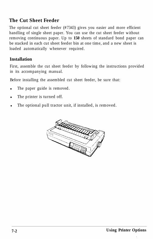
The Cut Sheet FeederThe optional cut sheet feeder (#7343) gives you easier and more efficienthandling of single sheet paper. You can use the cut sheet feeder withoutremoving continuous paper. Up to 150 sheets of standard bond paper canbe stacked in each cut sheet feeder bin at one time, and a new sheet isloaded automatically whenever required.
Installation
First, assemble the cut sheet feeder by following the instructions providedin its accompanying manual.
Before installing the assembled cut sheet feeder, be sure that:
l The paper guide is removed.
l The printer is turned off.
l The optional pull tractor unit, if installed, is removed.
7-2 Using Printer Options
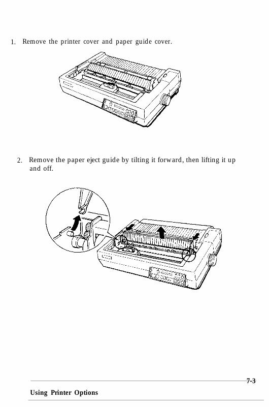
1. Remove the printer cover and paper guide cover.
2. Remove the paper eject guide by tilting it forward, then lifting it upand off.
Using Printer Options
7-3

3. Pull the paper bail toward you.
4. Hold the assembled cut sheet feeder in both hands and fit its notchesover the red pins in the printer.
7-4 Using Printer Options

5. Reattach the printer cover.
6. Turn on the printer.
7. Be sure that the printer is off line. If it is not, press the ON LINEbutton to set the printer off line.
Using Printer Options 7-5

8. Press the PAPER SELECT button until the CSF light comes on andCSF bin 1 is briefly displayed. Press the PAPER SELECT button againif you wish to select CSF bin 2. If continuous paper is loaded, thepaper is reverse-fed.
Loading paper
No matter which cut sheet feeder (CSF) bin you select, the paper isloaded in the same way. The procedure for loading CSF bin 1 (the frontbin) is described in the following example.
Before loading the paper, be sure that:
l The cut sheet feeder is securely installed onto the printer.
l The desired bin is selected by the PAPER SELECT button.
1. Pull the left and right paper levers of the selected bin forward untilthe paper guides retract and lock open to allow for paper loading.
7-6 Using Printer Options

2. Slide the left paper guide all the way to the left. Next, slide the rightpaper guide to roughly match the width of your paper.
3. Take a stack of paper and fan it. Next, tap the paper on a flat surfaceto even up the stack.
Using Printer Options 7-7

4. Insert the paper along the left paper guide. Then, adjust the positionof the right paper guide so that it closely matches your paper’s width.Be sure that the position of the guide allows the paper to move upand down freely.
5. Push the paper levers back until the paper is clamped against theguide rollers. The levers will not close completely if too much paperis used. If this happens, remove some paper from the stack and tryagain.
7-8 Using Printer Options

6. You can choose to have the printer eject the sheets with the printedside facing downward or upward. To have the printer eject the sheetswith the printed side facing downward, pull the front lever on theright side of the cut sheet feeder forward. To eject the sheets with theprinted side facing upward, push this lever back.
If you eject the sheets with the printed side facing downward, thepaper is collated as it prints. If you eject the sheets with the printedside facing upward, sheets are fed in reverse order but more sheetscan be stacked in the cut sheet feeder.
Caution: Never move this lever during printing.
Testing the printer in the cut sheet feeder mode
When you perform the cut sheet feeder self test, the printer counts thenumber of lines on the page and prints out this number at the bottom ofthe first page. The number of lines counted by the printer becomes thedefault page length setting. This setting, however, can be overriden bySelecType or by software commands.
Using Printer Options 7-9

The procedure for running the self test is the same as when the cut sheetfeeder mode is off.
Before running the self test in the cut sheet feeder mode, be sure that:
l The desired bin is selected by PAPER SELECT button.
l The printer is turned off.
l A stack of paper is inserted.
1. While holding down the LINE FEED button (draft mode) or FORMFEED button (LQ mode), turn on the printer.
The following figure shows part of the printout for the first sheet of thedraft mode self test. The printout of the second sheet is similar to theoriginal self test described in Chapter 1.
This i s t h e f i r s t l i n e .
This i s ljne XX.
7-10 Using Printer Options

2. The self test continues until the paper runs out or until you press theON LINE button. To stop the test, press the ON LINE button.
3. To end the self test, if paper is loaded, press the LOAD/EJECT buttonto eject it. Then, turn off the printer.
Loading envelopesEnvelopes are loaded in much the same way as regular paper.
To load envelopes, be sure that:
l The printer is off line.
l The CSF light is on.
l CSF bin 1 is selected by PAPER SELECT button.
Using Printer Options 7-11

Caution: When printing envelopes, be sure to load them into bin 1,never into bin 2.
1. Take a stack of envelopes and fan it; then tap the stack on a flatsurface to even it up. Insert the envelopes into the front bin.
2. Push down on the two front levers until they lock into position.
7-12 Using Printer Options

3. Press the LOAD/EJECT button to load an envelope. Then press theON LINE button to start printing.
Using the cut sheet feeder
After stacking paper in the cut sheet feeder, be sure that the ON LINE lightis lit. When the printer is on line, a new sheet of paper loadsautomatically whenever a printable character or line feeding command issent to the printer. Subsequent sheets are automatically loaded as needed.
Note: Be sure that you run the self test described earlier in this chapterthe first time you use the cut sheet feeder and whenever you change toa different paper size.
When the selected paper bin is empty, the printer automatically goes offline and the PAPER OUT light goes on. To resume printing, stack morepaper, then press the ON LINE button.
Note: If you turn off your printer during a paper out or paper jamcondition, any data remaining in the printer’s buffer is discarded.
Using Printer Options 7-13

Control panel operation
To operate the cut sheet feeder from the control panel when theprinter is in cut sheet feeder mode, be sure that the printer is off line.
LINE FEED: Press to feed the paper one line, or hold itdown to feed the paper continuously.
FORM FEED:
LOAD EJECT:
When there is no paper in the printer, pressto load the paper manually. (However, notethat paper loads automatically when youprint.) When there is paper in the printer,press to eject the sheet without loading thenext sheet.
When there is no paper in the printer, pressto load the paper manually. (However, notethat paper loads automatically when youprint.) When there is paper in the printer,press to eject the sheet without loading thenext sheet.
Software operation
The following commands cause the printer to eject the sheet in theprinter without loading the next sheet. The printer must be on lineto control the cut sheet feeder with software commands: FF and ESCEM R.
Note: The ESC EM command controls the operation of the cutsheet feeder. For more information about this command, seeChapter 8.
If the paper reaches the bottom of the print area when any of thefollowing line feeding commands is used, the sheet in the printeris automatically ejected and the next sheet is loaded: LF, VT, andESC J.
7-14 Using Printer Options

Setting up your software
When you switch to cut sheet feeder fed paper from another paper feedsystem, you usually need to change the settings of your softwareprogram. Because of the physical requirements of feeding a single sheetof paper, sheet feeders always create an unprintable top and bottommargin on each sheet. To work properly, your software program needs toknow how many printable lines are available on the page.
Paper comes in many different sizes, and it is sometimes difficult to knowexactly how many printable lines per page you have. When you run the selftest for the cut sheet feeder, the LQ-2550 automatically counts and printsout the number of lines that are available on any size of paper. This is thenumber of lines you should use as the page length in your software setup.See the section on testing the printer in this chapter for details.
In addition to the number of printable lines, which your software may referto as page length or form length, you may need to set the top margin, thebottom margin, and the actual number of lines to be printed on the page.The cut sheet feeder for the LQ-2550 normally creates a two-line unprintabletop margin. Therefore, if you want a total top margin of six lines (oneinch), you should set the top margin in your software to four lines. TheLQ-2550 sheet feeder usually creates an unprintable bottom margin of aboutthree lines, so to create a total bottom margin of six lines (one inch), youshould set the bottom margin in your software to three lines. With a totalpage length of 61 printable lines, for example, the number of printed linesper page would be 54 (9 inches).
Some software designed only for printing on continuous forms will notuse the Form Feed or ESC EM commands recommended for proper sheetfeeder operation. This type of software may not have a sheet feedersetup mode or allow for margin settings, and it may only use Line Feedsto advance to the next form. Your sheet feeder can still work with mostof these applications without any problems. Simply insert the paper youwill be using into the sheet feeder, use the self test to print out thenumber of printable lines, then use that number of lines as the pagelength setting in your software. If you change paper sizes, repeat thisprocess. Your sheet feeder will work as if it were feeding a continuousform. If your software does not allow you to set the page length, consultyour software manufacturer.
Using Printer Options 7-15
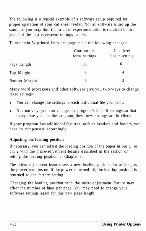
The following is a typical example of a software setup required forproper operation of your cut sheet feeder. Not all software is set up thesame, so you may find that a bit of experimentation is required beforeyou find the best equivalent settings to use.
To maintain 54 printed lines per page make the following changes:
Continuous Cut sheetform settings feeder settings
Page Length 66 61
Top Margin 6 4
Bottom Margin 6 3
Many word processors and other software give you two ways to changethese settings:
l You can change the settings in each individual file you print.
l Alternatively, you can change the program’s default settings so thatevery time you use the program, these new settings are in effect.
If your program has additional features, such as headers and footers, youhave to compensate accordingly.
Adjusting the loading position
If necessary, you can adjust the loading position of the paper in bin 1 orbin 2 with the micro-adjustment feature described in the section onsetting the loading position in Chapter 3.
The micro-adjustment feature sets a new loading position for as long asthe power remains on. If the power is turned off, the loading position isreturned to the factory setting.
Changing the loading position with the micro-adjustment feature mayaffect the number of lines per page. You may need to change yoursoftware settings again for this new page length.
7-16 Using Printer Options

Switching between the cut sheet feeder and continuous paper
The LQ-2550 allows you to easily switch between the cut sheet feederand the tractor feeding system without having to remove either thefeeder or the continuous paper supply.
To switch between these two paper feeding systems, be sure that:
l Continuous paper is loaded in the standby position.
l The cut sheet feeder is installed.
l The printer is off line.
Note: If you wish to use the short tear-off feature, you can tear off theperforation of the continuous paper at the cut sheet feeder’s tear-offedge. See Chapter 3 for more information on the short tear-off feature.
1. To switch from cut sheet feeder operation to continuous paper, pressthe PAPER SELECT button until the TRACTOR light goes on.Continuous paper is now fed to its loading position, and the frontsection of the cut sheet feeder is automatically tilted forward.
Using Printer Options 7-17
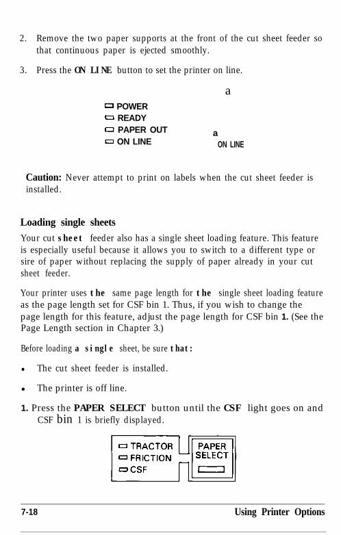
2. Remove the two paper supports at the front of the cut sheet feeder sothat continuous paper is ejected smoothly.
3. Press the ON LINE button to set the printer on line.
0 POWER0 READY0 PAPER OUTo ON LINE
a
aON LINE
Caution: Never attempt to print on labels when the cut sheet feeder isinstalled.
Loading single sheets
Your cut sheet feeder also has a single sheet loading feature. This featureis especially useful because it allows you to switch to a different type orsire of paper without replacing the supply of paper already in your cutsheet feeder.
Your printer uses the same page length for the single sheet loading featureas the page length set for CSF bin 1. Thus, if you wish to change thepage length for this feature, adjust the page length for CSF bin 1. (See thePage Length section in Chapter 3.)
Before loading a single sheet, be sure that:
l The cut sheet feeder is installed.
l The printer is off line.
1. Press the PAPER SELECT button until the CSF light goes on andCSF bin 1 is briefly displayed.
7-18 Using Printer Options
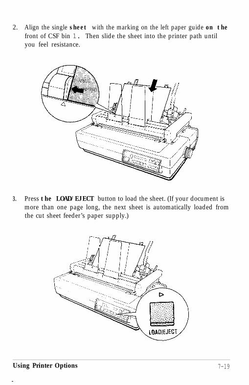
2. Align the single sheet with the marking on the left paper guide on thefront of CSF bin 1. Then slide the sheet into the printer path untilyou feel resistance.
3. Press the LOAD/EJECT button to load the sheet. (If your document ismore than one page long, the next sheet is automatically loaded fromthe cut sheet feeder’s paper supply.)
Using Printer Options 7-19

Removing the cut sheet feederBefore removing the cut sheet feeder, be sure that:
l The printer is turned off.
l Any paper stacked in the cut sheet feeder is removed.
1. Tilt the back section of the cut sheet feeder forward to release itsnotches from the printer’s red pins and remove the cut sheet feeder.
7-20 Using Printer Options

2. Replace the paper eject guide by fitting its notches onto the redpins inside the printer at each side, then tilting the paper ejectguide back slightly.
3. Store the removed cut sheet feeder in its original box andpacking materials.
The Pull Tractor
The optional pull tractor (#7314) provides optimum continuouspaper handling. It is best used for continuous pre-printed forms,multi-part forms, labels, and to obtain the highest quality graphics.For best results, use the pull tractor along with the built-in pushtractor, as described in this section.
The short tear-off feature cannot be used with the pull tractor.Before you start printing with the pull-off tractor, make sure that theTEAR OFF light is off.
Installation
Before installing the pull tractor, be sure that:
l The paper guide is removed.
l The printer is turned off.
Using Printer Options 7-21

l The cut sheet feeder, if installed, is removed.
1. Remove the printer cover and paper guide cover.
2. Pull the paper bail toward you.

3. Remove the paper eject guide by tilting it forward, then lifting it upand off.
4. Hold the pull tractor with the gears to the right. Fit the rear notcheson the tractor over the rear mounting rods on the printer, as shownin the following illustration.
Using Printer Options

5. Tilt the tractor unit toward you until the front latches click in placeover the red front mounting rods of the printer.
6. Attach the printer cover.
Loading paper
Before loading continuous paper with the pull tractor, be sure that:
l The pull tractor is installed.
l The printer cover is installed.
l The paper guide cover is removed.
l The paper guide is removed.
7-24 Using Printer Options

Caution: The short tear-off function cannot be used with the pulltractor. Before you start printing with the pull tractor, be sure that theHIT0 TEfiR DFF option in SelecType is off.
1. Turn on the printer. Then press the PAPERthe TRACTOR light comes on.
SELECT button until
2. Load continuous paper in the push tractor as described in steps 2-7in the section on loading continuous paper in Chapter 2, with oneexception. In step 2, position the left sprocket unit about 1/4 of aninch from the left before locking it in place.
Using Printer Options 7-25

3. After the paper is loaded in the push tractor, see that the printer is offline. Press the LOAD/EJECT button to load the paper. Then press theFORM FEED button to advance the paper one page so that you can fitthe paper onto the pull tractor.
4. Open the sprocket covers, and release the sprocket lock levers.
7-26 Using Printer Options

5. Adjust the sprocket units to match the width of the paper and adjustthe paper supports so they are evenly placed between the sprocketunits.
6. Fit the holes of the paper over the tractor pins of the sprocket units,adjusting the position of the sprocket units as necessary.
Using Printer Options
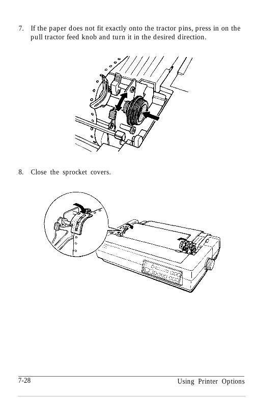
7. If the paper does not fit exactly onto the tractor pins, press in on thepull tractor feed knob and turn it in the desired direction.
8. Close the sprocket covers.
7-28 Using Printer Options

9. See that the paper is not crooked or wrinkled and lock the sprocketunits in place.
10. Attach the paper guide and lower it so that it is resting on top of theprinter. Center both edge guides.
Using Printer Options 7-29

11. Align the pins of the pull tractor cover with the slots on the printerand attach the cover.
12. Press the ON LINE button to set the printer on line.
0 POWER0 READY0 PAPER OUTo ON LINE
ON LINE
7-30 Using Printer Options

Caution: Before you begin printing, be sure to check the page lengthand skip over perforation settings, and readjust the settings ifnecessary. Setting procedures are described in Chapter 3.
Removing the pull tractorBefore removing the pull tractor, be sure that:
l The printer is turned off.
l The pull tractor cover and printer cover are removed.
l Any paper loaded in the unit is removed.
l The paper guide is removed.
Using Printer Options 7-31
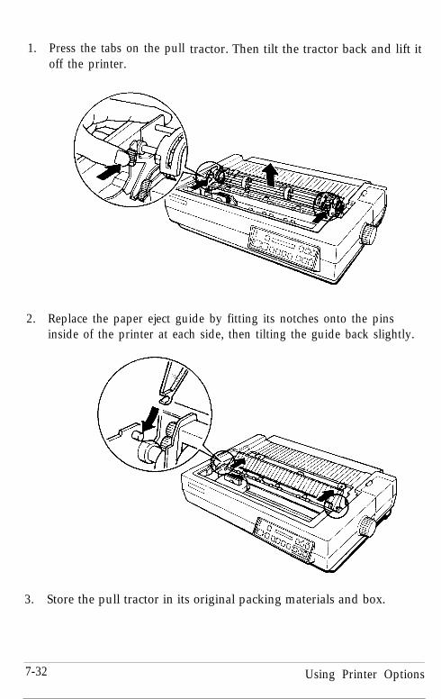
1. Press the tabs on the pulloff the printer.
tractor. Then tilt the tractor back and lift it
2. Replace the paper eject guide by fitting its notches onto the pinsinside of the printer at each side, then tilting the guide back slightly.
3. Store the pull tractor in its original packing materials and box.
7-32 Using Printer Options
Interface BoardsThere are a number of optional interfaces that can be used to supplementthe capabilities of your printer’s built-in serial and parallel interfaces.
Choosing an interface
The following information should give you a general idea of thefeatures provided by these optional interface boards. Optionalinterfaces can be divided into the following categories:
l Serial interfaces.
l The IEEE-488 interface offers standardized connections, trouble-freeoperation, and the ability to connect computers, printers, andother devices on the same line so they can share data freely.
If you are not sure whether you need an optional interface, or wouldlike to know more about interfaces, check with your Epson dealer.
Compatible interfaces
The following is a list of Epson interfaces that are compatible with yourLQ printer.
Interface number Name#8143 New serial interface#8148 Intelligent serial interface#8165 Intelligent IEEE-488 Interface
Using Printer Options 7-33

All Epson interfaces have the EPSON name printed on them. If theboard has an identification code printed on it, it is a four-digit numberbeginning with 8, and should correspond to one of the numbers listed inthe table above.
Installing the interface boardThe optional interface boards available for your printer are easy toinstall. The only tool needed is a cross-head screwdriver.
Before installing an optional interface board, be sure that:
l Continuous feed paper is removed.
l The printer and computer are turned off.
l The parallel cable is disconnected from the printer and the computer.
l The paper guide and the paper guide cover are removed.
l The printer cover is removed.
l Any installed printer option (such as the cut sheet feeder or pulltractor) is removed.
l The cable cover is removed.
l Any DIP switches or jumpers on the interface board are setaccording to the instructions in your interface board manual.
7-34 Using Printer Options

Removing the upper case
1. Unplug the power cable from the electrical outlet. Then unplug thecable from the rear of the printer.
WARNING: High voltages are present inside the printerwhen the power is on. Do not attempt to remove the uppercase unless the printer is turned off and the power cord isunplugged. Also, try not to touch contacts on the circuitboard of the printer because many of the components can bedestroyed by the static electricity in your body.
2. Remove the font compartment cover.
Using Printer Options 7-35
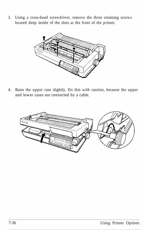
3. Using a cross-head screwdriver, remove the three retaining screwslocated deep inside of the slots at the front of the printer.
4. Raise the upper case slightly. Do this with caution, because the upperand lower cases are connected by a cable.
7-36 Using Printer Options
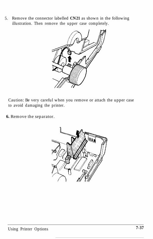
5. Remove the connector labelled CN21 as shown in the followingillustration. Then remove the upper case completely.
Caution: Be very careful when you remove or attach the upper caseto avoid damaging the printer.
6. Remove the separator.
Using Printer Options 7-37
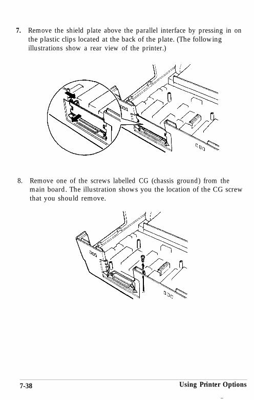
7. Remove the shield plate above the parallel interface by pressing in onthe plastic clips located at the back of the plate. (The followingillustrations show a rear view of the printer.)
8. Remove one of the screws labelled CG (chassis ground) from themain board. The illustration shows you the location of the CG screwthat you should remove.
7-38 Using Printer Options

Installing the board
There are two basic types of interface board designs, which slightlychange the way they are installed in the printer. (The frame ground wireis attached for one type and not attached for the other.) This differencedoes not affect the operation of the interface in any way. Check to seewhich type of interface board you have and then follow the instructionsfor that type of board.
FG wire not attached
1. Use the CG screw to attach the round end of the FG (frame ground)wire to the main board and position the other end as shown.
Using Printer Options 7-39

2. Carefully insert the pins on the optional interface board into themating connector on the main board; then secure the board withthree of the screws provided.
3. Attach the plug end of the FG wire onto the FG pin located on top ofthe interface board.
4. Reattach the upper case as described in the section immediatelyfollowing the next section.
7-40 Using Printer Options

FG wire attached
1. Carefully place the interface board next to the printer as shownbelow. Use the CG screw to connect the round end of the FG (frameground) wire to the main board.
2. Holding the interface board level, rotate it clockwise into positionand attach it to the main board. Make sure the connector pins areproperly inserted into the mating connector.
Using Printer Options 7-41

3. Secure the board with three of the screws provided.
4. Reattach the upper case as described in the following section.
Attaching the upper case
1. Fit the hinges of the upper case into the openings in the lower case;then partially lower the upper case.
7 - 4 2 Using Printer Options
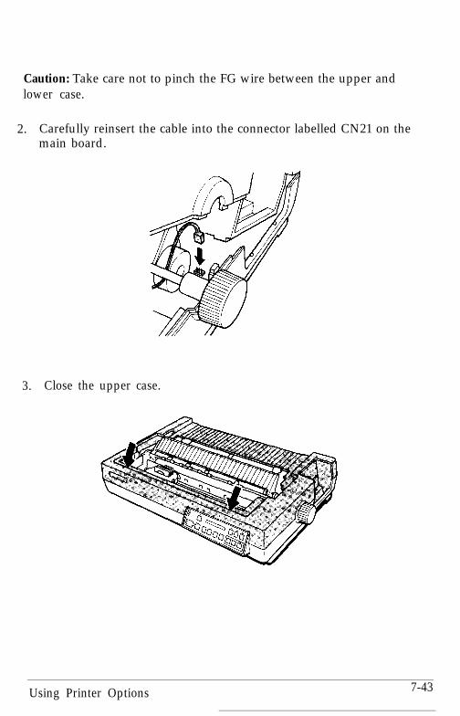
Caution: Take care not to pinch the FG wire between the upper andlower case.
2. Carefully reinsert the cable into the connector labelled CN21 on themain board.
3. Close the upper case.
Using Printer Options 7-43

4. Secure the case with the three screws.
5. Reattach the font compartment cover.
6. Now that you have completed the installation of the optionalinterface board, replace any parts or options you removed earlier.(Note that the separator and the shield plate are not reattached.)
Using Printer Options
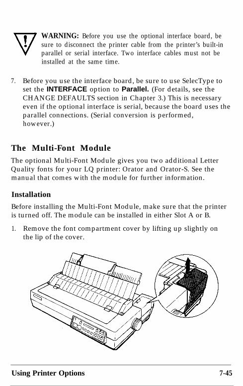
WARNING: Before you use the optional interface board, besure to disconnect the printer cable from the printer’s built-inparallel or serial interface. Two interface cables must not beinstalled at the same time.
7. Before you use the interface board, be sure to use SelecType toset the INTERFACE option to Parallel. (For details, see theCHANGE DEFAULTS section in Chapter 3.) This is necessaryeven if the optional interface is serial, because the board uses theparallel connections. (Serial conversion is performed,however.)
The Multi-Font ModuleThe optional Multi-Font Module gives you two additional LetterQuality fonts for your LQ printer: Orator and Orator-S. See themanual that comes with the module for further information.
Installation
Before installing the Multi-Font Module, make sure that the printeris turned off. The module can be installed in either Slot A or B.
1. Remove the font compartment cover by lifting up slightly onthe lip of the cover.
Using Printer Options 7-45

2. Plug the Multi-Font Module carefully into either Slot A or B.The arrow on the module should point toward the printer.
3. Reattach the font compartment cover.
7-46 Using Printer Options

Selecting a font
You can select a font in three different ways: by using softwarecommands, by pressing the panel buttons, or by SelecType settings.To select a font via the panel button, simply press the FONT buttonuntil the desired font is displayed.
The following samples show the character set available for theseadditional fonts.
FONTq.... ,__: .I ;.., :.;...:/ :,_,: j, i,,.: / I.. ,,.
ORATOR
! "#$%& ' ( > *+, - . /Q122456789: ; (= >?AABCDEFGHI JKLMNO~$@ST~~~X~{ @,,JYEXZEUE FUEAAAACEEEIIIA ii!
EF@;+$@IWPQR+!~
UNNAOjrl~~iOKROOOUUYOU$E~~~AIO
WE'VE JUST SEEN YOUR EXCELLENT AD FORMINIATURE ZEBRAS IN A RECENT BACK ISSUE OFTRADER'S TIMES.
ORATOR-S
!"#$X&'()*+,-./Q122456789:;(=)?tiABCDEFGHIJKLMNO@$TUVWXY< q§ a$ efgh~$~~nopsrsfy~vxyzeue $ti~~aaace&?iA EfunNQ!&,r~~$i~~
aeRooouuyOU$EYPtfaio
We've just seen your excellent ad forminiature zebras in a recent back issue ofTrader's Times.
Using Printer Options 7-47

Chapter 8
Command Summary
Commands in Numerical Order . . . . . . . . . . . . . . . . . . . . . . . . . . . . . . . 8-5
Commands Arranged by Topic . . . . . . . . . . . . . . . . . . . . . . . . . . . . . . . . 8-8Printer Operation . . . . . . . . . . . . . . . . . . . . . . . . . . . . . . . . . . . . . . . . . 8-8MSB Control . . . . . . . . . . . . . . . . . . . . . . . . . . . . . . . . . . . . . . . . . . . . 8-11Data Control . . . . . . . . . . . . . . . . . . . . . . . . . . . . . . . . . . . . . . . . . . . . 8-12Vertical Motion . . . . . . . . . . . . . . . . . . . . . . . . . . . . . . . . . . . . . . . . . . 8-13Horizontal Motion . . . . . . . . . . . . . . . . . . . . . . . . . . . . . . . . . . . . . . . 8-18Overall Printing Style . . . . . . . . . . . . . . . . . . . . . . . . . . . . . . . . . . . . 8-21Print Size and Character Width . . . . . . . . . . . . . . . . . . . . . . . . . . . . 8-23Print Enhancement . . . . . . . . . . . . . . . . . . . . . . . . . . . . . . . . . . . . . . . 8-27Word Processing . . . . . . . . . . . . . . . . . . . . . . . . . . . . . . . . . . . . . . . . . 8-30Character Tables . . . . . . . . . . . . . . . . . . . . . . . . . . . . . . . . . . . . . . . . . 8-31User-Defined Characters . . . . . . . . . . . . . . . . . . . . . . . . . . . . . . . . . . 8-32Graphics . . . . . . . . . . . . . . . . . . . . . . . . . . . . . . . . . . . . . . . . . . . . . 8-34
Command Summary 8-1

This chapter lists and describes all the commands available on yourprinter. The Command Summary is divided by topics, but there is a listof the commands in numerical order beginning on page 8-5. If you knowwhich command you are looking for, see this list to find the page numberwhere it is described.
The Quick Reference card at the end of the book also contains a list ofthe commands divided by topic, with page references that direct you tofull explanations of the commands.
The commands described in this summary are divided into the followingsubjects:
Printer operation Print size and character widthMSB control Print enhancementData control Word processingVertical motion Character tablesHorizontal motion User-defined charactersOverall printing style Graphics
Each command has a format section and a comments section. Theformat section gives the ASCII, decimal, and hexadecimal codes for thecommand. The comments section describes the effect of the commandand gives any additional information necessary for using it.
The format section includes:
ASCII: the sequence in standard ASCII charactersDecimal: the sequence in decimal numbersHexadecimal: the sequence in hexadecimal numbers
8-2 Command Summary

All three formats are equivalent, so you can pick the one best suited toyour purpose. Variables are represented by italicized letters such as n, nl,and m. The variables are explained in the comments section.
Examples
The simplest type of command consists of sending a single character tothe printer. For instance, to print in condensed mode, you send the code15.
ASCII code: SIDecimal: 15Hexadecimal: OF
More complex commands consist of two or more character codes. Forexample, to print in the proportional mode the code format is thefollowing:
ASCII: ESC nDecimal: 27 1:2 nHexadecimal: 1B 70 n
In this case n can be either 1 (on) or 0 (off), to begin or end proportionalprinting. To turn on proportional printing from BASIC, use the followingcommand:
LPRINT CHR$(27);“p”;CHR$(l)
For the following commands that use only 0 or 1 for the variable, eitherthe ASCII codes 0 and 1 or the ASCII characters 0 and 1 can be used:
ESC U, ESC x, ESC p, ESC W, ESC S, ESC -, ESC %, and ESC w.
For example, in BASIC you can turn on double-wide with either of thesestatements:
LPRINT CHR$(27);‘W”;CHR!$(l) . . . . . . . . . . . . . . ASCII codeLPRINT CHR$(27);“W”;“l” . . . . . . . . . . . . . . . . . . . ASCII character
Command Summary 8-3
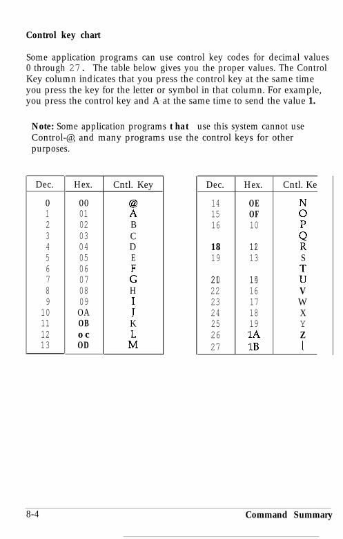
Control key chart
Some application programs can use control key codes for decimal values0 through 27. The table below gives you the proper values. The ControlKey column indicates that you press the control key at the same timeyou press the key for the letter or symbol in that column. For example,you press the control key and A at the same time to send the value 1.
Note: Some application programs that use this system cannot useControl-@, and many programs use the control keys for otherpurposes.
Dec. Hex.
0 001 012 023 034 045 056 067 078 089 09
10 OA11 OB12 o c13 OD
Cntl. Key
zBCDE
:H
fK
tl
Dec. Hex. Cntl. Ke
14 OE15 OF :16 10
17 1118 12 P19 13 S
20 1421 15 z22 16 V23 17 W24 18 X25 19 Y26 1A Z27 1B [
8-4 Command Summary

Commands in Numerical OrderThe following list shows control codes and ESC sequences (withtheir decimal and hexadecimal values), and the page number wherethe complete command description can be found.
ASCII Dec. Hex Description Page
BEL 7 07BS 8 08HT 9 09LF 10 0AVT 11 0BFF 12 0CCR 13 0Ds o 14 0ESI 15 0FDC1 17 11DC2 18 12DC3 19 13DC4 20 14CAN 24 18DEL 127 7FESC SO 14 0EESC SI 15 OFESC EM 25 19ESC SP 32 20ESC ! 33 21ESC # 35 23ESC $ 36 24ESC % 37 25ESC & 38 26ESC * 42 2AESC (- 40 28ESC + 43 2BESC - 45 2D
Command Summary
Beeper .......................................................... 8-12Backspace ................................................... 8-19Tab horizontally ....................................... .8-20Line feed .................................................... .8-14Tab vertically ............................................. 8-17Form feed .................................................... 8-13Carriage return .......................................... 8-12Select double-wide mode (1 line). .......... .8-25Select condensed mode ........................... .8-24Select printer ................................................ 8-8Cancel condensed mode ......................... .8-25Deselect printer ........................................... .8-9Cancel double-wide mode (1 line). ........ .8-26Cancel line ................................................. .8-12Delete character .......................................... .8-9Select double-wide mode (1 line). .......... .8-25Select condensed mode ........................... .8-24Cut sheet feeder mode ............................. .8-10Set intercharacter space ........................... .8-30Master Select ............................................. .8-22Cancel MSB control .................................. .8-11Set absolute print position ...................... .8-19Select user-defined set ............................. .8-33Define user-defined characters .............. .8-32Select graphics mode ............................... .8-35Select Line .................................................. .8-29Select n/360-inch line spacing.. .............. .8-16Turn underlining on/off ......................... .8-29
8-5
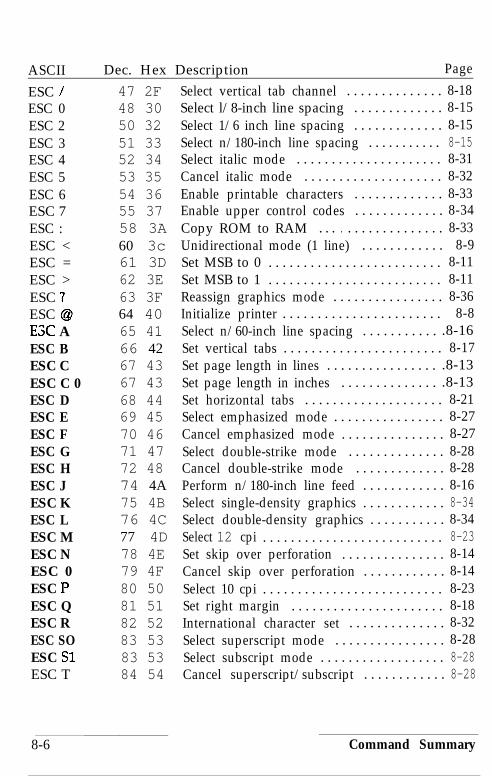
ASCII Dec. Hex Description Page
ESC / 47 2FESC 0 48 30ESC 2 50 32ESC 3 51 33ESC 4 52 34ESC 5 53 35ESC 6 54 36ESC 7 55 37ESC : 58 3AESC < 60 3cESC = 61 3DESC > 62 3EESC ? 63 3FESC @ 64 40ESC A 65 41ESC B 66 42ESC C 67 43ESC C 0 67 43ESC D 68 44ESC E 69 45ESC F 70 46ESC G 71 47ESC H 72 48ESC J 74 4AESC K 75 4BESC L 76 4CESC M 77 4DESC N 78 4EESC 0 79 4FESC I=’ 80 50ESC Q 81 51ESC R 82 52ESC SO 83 53ESC Sl 83 53ESC T 84 54
Select vertical tab channel . . . . . . . . . . . . . . 8-18Select l/8-inch line spacing . . . . . . . . . . . . . 8-15Select 1/6 inch line spacing . . . . . . . . . . . . . 8-15Select n/180-inch line spacing . . . . . . . . . . . 8-15Select italic mode . . . . . . . . . . . . . . . . . . . . . 8-31Cancel italic mode . . . . . . . . . . . . . . . . . . . . 8-32Enable printable characters . . . . . . . . . . . . . 8-33Enable upper control codes . . . . . . . . . . . . . 8-34Copy ROM to RAM . . . . . . . . . . . . . . . . . . 8-33Unidirectional mode (1 line) . . . . . . . . . . . . 8-9Set MSB to 0 . . . . . . . . . . . . . . . . . . . . . . . . . 8-11Set MSB to 1 . . . . . . . . . . . . . . . . . . . . . . . . . 8-11Reassign graphics mode . . . . . . . . . . . . . . . . 8-36Initialize printer . . . . . . . . . . . . . . . . . . . . . . . 8-8Select n/60-inch line spacing . . . . . . . . . . . .8-16Set vertical tabs . . . . . . . . . . . . . . . . . . . . . . . 8-17Set page length in lines . . . . . . . . . . . . . . . . .8-13Set page length in inches . . . . . . . . . . . . . . .8-13Set horizontal tabs . . . . . . . . . . . . . . . . . . . . 8-21Select emphasized mode . . . . . . . . . . . . . . . . 8-27Cancel emphasized mode . . . . . . . . . . . . . . . 8-27Select double-strike mode . . . . . . . . . . . . . . 8-28Cancel double-strike mode . . . . . . . . . . . . . 8-28Perform n/180-inch line feed . . . . . . . . . . . . 8-16Select single-density graphics . . . . . . . . . . . . 8-34Select double-density graphics . . . . . . . . . . . 8-34Select 12 cpi . . . . . . . . . . . . . . . . . . . . . . . . . . 8-23Set skip over perforation . . . . . . . . . . . . . . . 8-14Cancel skip over perforation . . . . . . . . . . . . 8-14Select 10 cpi . . . . . . . . . . . . . . . . . . . . . . . . . . 8-23Set right margin . . . . . . . . . . . . . . . . . . . . . . 8-18International character set . . . . . . . . . . . . . . 8-32Select superscript mode . . . . . . . . . . . . . . . . 8-28Select subscript mode . . . . . . . . . . . . . . . . . . 8-28Cancel superscript/subscript . . . . . . . . . . . . 8-28
8-6 Command Summary

ASCIIESC UESC WESC YESC ZESC \ESC aESC bESC gESC kESC 1ESC pESC qESC rESC tESC wESC x
Dec. Hex85 5587 5789 5990 5A92 5C97 6198 62103 67107 6B108 6C112 70113 71114 72116 74119 77120 78
Description PageUnidirectional mode on/off . . . . . . . . . . . . . 8-10Turn double-wide mode on/off . . . . . . . . . . 8-25High-speed double-density graphics . . . . . 8-35Quadruple-density graphics . . . . . . . . . . . . . 8-35Set relative print position . . . . . . . . . . . . . . . 8-20Select justification . . . . . . . . . . . . . . . . . . . . . 8-30Set vertical tabs in channels . . . . . . . . . . . . . 8-17Select 15 cpi . . . . . . . . . . . . . . . . . . . . . . . . . . 8-23Select typestyle family . . . . . . . . . . . . . . . . . 8-22Set left margin . . . . . . . . . . . . . . . . . . . . . . . . 8-18Turn proportional mode on/off . . . . . . . . . . 8-24Select character style . . . . . . . . . . . . . . . . . . 8-29Select printing color . . . . . . . . . . . . . . . . . . . 8-27Select character table . . . . . . . . . . . . . . . . . . 8-31Turn double-high mode on/off . . . . . . . . . . 8-26Select Letter Quality or draft . . . . . . . . . . . . 8-21
Command Summary 8-7
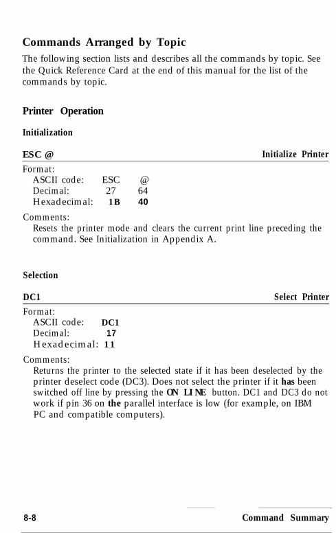
Commands Arranged by TopicThe following section lists and describes all the commands by topic. Seethe Quick Reference Card at the end of this manual for the list of thecommands by topic.
Printer Operation
Initialization
ESC @ Initialize Printer
Format:ASCII code: ESC @Decimal: 27 64Hexadecimal: 1B 40
Comments:Resets the printer mode and clears the current print line preceding thecommand. See Initialization in Appendix A.
Selection
DC1 Select PrinterFormat:
ASCII code: DC1Decimal: 17Hexadecimal: 11
Comments:Returns the printer to the selected state if it has been deselected by theprinter deselect code (DC3). Does not select the printer if it has beenswitched off line by pressing the ON LINE button. DC1 and DC3 do notwork if pin 36 on the parallel interface is low (for example, on IBMPC and compatible computers).
8-8 Command Summary

DC3 Deselect Printer
Format:ASCII code: DC3Decimal: 19Hexadecimal: 13
Comments:Puts the printer into the deselected state until the select printer code(DCl) is received. The printer cannot be reselected with the ON LINEbutton.
DELFormat:
ASCII code: DELDecimal : 127Hexadecimal: 7F
Delete Character
Comments:Removes the last text character on the print line but does not affectcontrol codes.
Printing direction
ESC < Select Unidirectional Mode (one line)Format:
ASCII code: ESC <Decimal: 27 60H e x a d e c i m a l : 1 B 3 C
Comments:Printing is normally bidirectional. This command selects unidirectionalprinting for one line only. The print head moves to the extreme left(home) position, and printing takes place from left to right. Thiscommand is cancelled by a carriage return.
Command Summary 8-9

ESC U Turn Unidirectional Mode On/Off
Format:ASCII code: ESC U nDecimal: 27 85 nHexadecimal: 1B 55 n
Comments:The following values can be used for n:1: Mode is turned on.0: Mode is turned off.Printing is normally bidirectional. This command selects unidirectionalprinting for more accurate positioning during printing.
ESC EM Cut Sheet Feeder Control
Format:ASCII code: ESC EM nDecimal: 27 25 nHexadecimal: 1B 19 n
Comments:The following values can be used for n:1: Selects bin 1.2: Selects bin 2.R: Ejects a sheet. (No paper is loaded.)The command should not be used unless the automatic sheet feeder isinstalled and CSF has been selected using the PAPER SELECT button. Itis ignored if any value other than 1, 2, or R is used for n.
8-10 Command Summary

MSB control
MSB is the Most Significant Bit. MSB control (ESC =, ESC > , andESC #) does not work for graphics.
ESC = (equal)Format:
ASCII code: ESC =Decimal: 27 61Hexadecimal: 1B 3D
Set MSB to 0
Comments:Sets the MSB of all incoming data to 0. Some computers always senddata with the MSB set to 1, which means that italics or charactergraphics will always be printed. ESC = can overcome this problem.
ESC > Set MSB to 1
Format:ASCII code: ESC >Decimal: 27 62Hexadecimal: 1B 3E
Comments:Sets the MSB bit of all incoming data as 1.
ESC # Cancel MSB Control
Format :ASCII code: ESC #Decimal : 27 35Hexadecimal: 1B 23
Comments:Cancels the MSB control set by ESC = or ESC > .
Command Summary 8-11

Beeper
BEL BeewrFormat:
ASCII code: BELDecimal: 7Hexadecimal: 07
Comments:Sounds the printer’s beeper.
Data Control
CR Carriage Return
Format:ASCII code: CRDecimal : 13Hexadecimal: OD
Comments:Prints the data in the buffer and returns the print position to the leftmargin. A line feed may be added if ALIT.0 FEED XT line on theparallel interface is held LOW.
Cancel Line
Format:ASCII code: CANDecimal: 24Hexadecimal: 18
Comments:Removes all text on the print line but does not affect control codes.
8-12 Command Summary
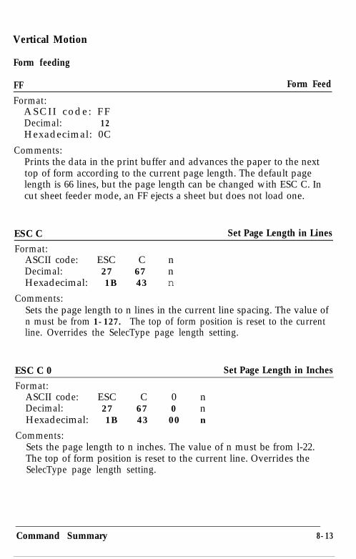
Vertical Motion
Form feeding
FF Form Feed
Format:ASCII code: FFDecimal: 12Hexadecimal: 0C
Comments:Prints the data in the print buffer and advances the paper to the nexttop of form according to the current page length. The default pagelength is 66 lines, but the page length can be changed with ESC C. Incut sheet feeder mode, an FF ejects a sheet but does not load one.
ESC C Set Page Length in Lines
Format:ASCII code: ESC C nDecimal: 27 67 nHexadecimal: 1B 43 n
Comments:Sets the page length to n lines in the current line spacing. The value ofn must be from 1-127. The top of form position is reset to the currentline. Overrides the SelecType page length setting.
ESC C 0 Set Page Length in Inches
Format:ASCII code: ESC C 0 nDecimal: 27 67 0 nHexadecimal: 1B 43 00 n
Comments:Sets the page length to n inches. The value of n must be from l-22.The top of form position is reset to the current line. Overrides theSelecType page length setting.
Command Summary 8-13

ESC NFormat:
ASCII code: ESC N nDecimal: 27 78 nHexadecimal: 1B 4E n
Set Skip Over Perforation
Comments:The variable n is the number of lines skipped between the last lineprinted on one page and the first line on the next page. For example,with the standard settings for line spacing (l/6-inch), and page length(66 lines), ESC N 6 prints 60 lines and then skips 6. This setting iscancelled by ESC C or ESC C 0. The value of n must be from 1-127.Overrides the SelecType skip over perforation setting.
ESC 0 Cancel Skir, Over Perforation
Format:ASCII code: ESC 0Decimal: 27 79Hexadecimal: 1B 4F
Comments:Cancels the skip over perforation set by ESC N. Overrides theSelecType skip over perforation setting.
Line feeding
LF Line Feed
Format:ASCII code: LFDecimal: 10Hexadecimal: 0A
Comments:When this command is received, the data in the print buffer is printedand the paper advances one line in the current line spacing.
8-14 Command Summary

ESC 0 (zero)
Format:ASCII code: ESC 0Decimal: 27 48Hexadecimal: 1B 30
Select l/&inch Line Spacing
Comments:Sets the line spacing to l/8 of an inch for subsequent line feedcommands. The 0 is the character zero and not decimal code 0.
ESC 2Format:
ASCII code: ESC 2Decimal: 27 50Hexadecimal: 1B 32
Select 1/6-inch Line Spacing
Comments:Sets the line spacing to l/6 of an inch for subsequent line feedcommands. The 2 is the character two and not decimal code 2. This isthe default at power on.
ESC 3Format:
ASCII code: ESC 3 nDecimal: 27 51 nHexadecimal: 1B 33 n
Select n/180-inch Line Spacing
Comments:Sets the line spacing to n/180 of an inch for subsequent line feedcommands. The 3 is the character three and not decimal code 3. Thisvalue of n must be from 0-255.
Command Summary 8-15

ESC +Format:
ASCII code: ESC + nDecimal: 27 43 nHexadecimal: 1B 2B n
Select n/360-inch Line Spacing
Comments:Sets the line spacing to n/360 of an inch for subsequent line feedcommands. This value of n must be from 0-255.
ESC A Select n/60-inch Line Spacing
Format:ASCII code: ESC A nDecimal: 27 65 nHexadecimal: 1B 41 n
Comments:Sets the line spacing to n/60 of an inch for subsequent line feedcommands. The value of n must be from 0-85.
ESC J Perform n/180-inch Line Feed
Format:ASCII code: ESC J nDecimal : 27 74 nHexadecimal: 1B 4A n
Comments:Advances the paper n/180 of an inch. The value of n must be from0-255. This command produces an immediate line feed but does notaffect subsequent line spacing and does not produce a carriage return.
8-16 Command Summary

Vertical tabbing
VTFormat:
ASCII code: VTDecimal: 11Hexadecimal: 0B
Tab Vertically
Comments:Advances the paper to the next tab setting in the channel selected byESC /. If no channel has been selected, channel 0 is used. If no verticaltabs have been set, the paper advances one line.
ESC B Set Vertical Tabs
Format:ASCII code: ESC B nl n2 . . . 0Decimal : 27 66 nl n2 . . . 0Hexadecimal: 1B 42 nl n2 . . . 00
Comments:Sets up to 16 vertical tabs in the current line spacing. Tab settings arenot affected by subsequent changes in line spacing. The tab settings areentered as nl, n2, etc., all from l-255, in ascending order. The 0 codeindicates the end of the command. All settings are stored in channel 0(see ESC b). ESC B 0 clears the tab settings.
ESC b Set Vertical Tabs in Channels
Format:ASCII code: ESC b c nl n2 . . . 0Decimal: 27 98 c nl n2 . . . 0Hexadecimal: 1B 62 c nl n2 . . . 00
Comments:Functions the same as ESC B, except that the variable c selects achannel for the vertical tabs, which must be between 0-7. Therefore,up to eight sets of vertical tabs can be set. The channels are selected byESC /. To clear the tabs in channel c use ESC b c 0.
Command Summary 8-17

ESC / Select Vertical Tab Channel
Format:ASCII code: ESC / cDecimal: 27 47 cHexadecimal: 1B 2F c
Comments:This command is used to select the vertical tab channel, with the valueof c from 0-7. All subsequent VT commands use the channel selectedby this command.
Horizontal Motion
Margins
ESC lFormat:
ASCII code: ESC 1 nDecimal: 27 108 nHexadecimal: 1B 6C n
Set Left Margin
Comments:Sets the left margin to n columns in the current character size. Settingsmade in the proportional mode are treated as 10 cpi. Use lowercase 1(as in left), not the numeral one. The minimum space between themargins is the width of one double-wide 10 cpi character.
ESC Q Set Right Margin
Format:ASCII code: ESC Q nDecimal: 27 81 nHexadecimal: 1B 51 n
Comments:Sets the right margin to n columns in the current character spacing.Settings made in the proportional mode are treated as 10 cpi. Theminimum space between the margins is the width of one double-wide10 cpi character.
8-18 Command Summary

Print head movement
BSFormat :
ASCII code: BSDecimal: 8Hexadecimal: 08
Backspace
Comments:Moves the print position one space to the left. Backspacing can beperformed up to, but not beyond, the left margin setting. Do not useBS with ESC a.
ESC $ Set Absolute Print Position
Format:ASCII code: ESC $ nl n2Decimal: 27 36 nl n2Hexadecimal: 1B 24 nl n2
Comments:This sequence specifies the distance from the left margin thatsubsequent characters are to be printed, using this formula: totalnumber of dots = n1 + (n2 X 256). Each unit equals 1/60th of aninch. The sequence is ignored and the previous setting remainseffective if the position specified is beyond the right margin.
Command Summary, 8-19

ESC \ Set Relative Print Position
Format:ASCII code: ESC 1 nl n2Decimal: 27 92 nl n2Hexadecimal: 1B 5C n7 n2
Comments:Determines the position (relative to the current position) at whichprinting of following data will start. To find nl and YL?, first calculate thedisplacement required in dots. If the displacement is to the left, subtractit from 65536. Send the resulting number using this formula: totalnumber of dots = nl + (256 X n2). The command is ignored if itwould move the print position outside the current margins. A unit is1/120th of an inch in draft and 1/180th of an inch in Letter Quality orproportional.
Horizontal tabbing
HTFormat:
ASCII code: HTDecimal : 9Hexadecimal: 09
Tab Horizontally
Comments:Advances the print position to the next horizontal tab setting. Thedefault settings are at intervals of 8 characters in the currently selectedcharacter spacing.
8-20 Command Summary

ESC D Set Horizontal Tabs
Format:ASCII code: ESC D nl n2 . . . 0Decimal: 27 68 nl n2 . . . 0Hexadecimal: 1B 44 nl n2 . . . 00
Comments:This command allows setting of up to 32 horizontal tabs, which areentered as nl, n2, n3, etc. (from l-255) with the 0 code terminatingthe command. The tab settings must be entered in ascending order;ESC D 0 clears all tabs. The settings on power up or after an ESC @command are every 8 characters. Tabs are set in the current cpi. Thetab settings do not change if the cpi is changed, and for proportionalprinting the size of 10 cpi characters determines the tab positions.
Overall Printing Style
ESC xFormat:
ASCII code: ESC nDecimal : 27 120 nHexadecimal: 1B 78 n
Select Letter Quality or Draft
Comments:The following values can be used for n:0: Selects the draft mode.1: Selects the Letter Quality (LQ) mode.Overrides the SelecType panel setting.
Command Summary 8-21

ESC k Select Typestyle Family
Format:ASCII code: ESC k nDecimal: 27 107 nHexadecimal: 1B 6B n
Comments:This command affects only the Letter Quality typestyle, not draft. Ifn = 0, the Roman typestyle in the printer is used. To select one of thefour other typestyles, use the family number of the font shown below.For example, to choose the Prestige font, use 3 for n.The following values can be used for n:0 = Roman1 = Sans Serif2 = Courier3 = Prestige4 = Script5 = OCR-B6 = OCR-A7=Orator (Optional)8=Orator-S (Optional)Overrides the SelecType setting.
ESC ! Master Select
Format:ASCII code: ESC ! nDecimal : 27 33 nHexadecimal: 1B 21 n
Comments:Selects any valid combination of the following modes: 10 cpi, 12 cpi,proportional, condensed, emphasized, double-strike, double-wide,italic, and underline. For details on how to set n, see the section onselecting typestyles with Master Select in Chapter 4.
8-22 Command Summary
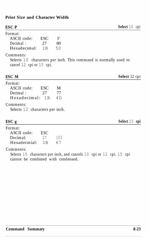
Print Size and Character Width
ESC P Select 10 cpi
Format:ASCII code: ESC I’Decimal : 27 80Hexadecimal: 1B 50
Comments:Selects 10 characters per inch. This command is normally used tocancel 12 cpi or 15 cpi.
ESC M Select 12 cpi
Format:ASCII code: ESC MDecimal : 27 77Hexadecimal: 1B 4D
Comments:Selects 12 characters per inch.
ESC g Select 15 cpi
Format:ASCII code: ESCDecimal: 27 103Hexadecmial: 1B 67
Comments:Selects 15 characters per inch, and cancels 10 cpi or 12 cpi. 15 cpicannot be combined with condensed.
Command Summary 8-23

ESC p Turn Proportional Mode On/Off
Format:ASCII code: ESC nDecimal: 27 112 nHexadecimal: 1B 70 n
Comments:The following values can be used for n:1: Mode is turned on.0: Mode is turned off.The width of proportional characters varies from character tocharacter. Therefore, a narrow letter like i receives less space than awide letter like W. The proportional widths are given in the charactertables, which appear in Appendix B. Proportional is not available indraft mode.
SI Select Condensed Mode
Format:ASCII code: SIDecimal: 15Hexadecimal: 0F
Comments:Prints characters at about 60 percent of their normal width. Forexample, the condensed 10 cpi mode has 17 characters per inch.Cannot be combined with 15 cpi.
ESC SI Select Condensed Mode
Format:ASCII code: ESC SIDecimal: 27 15Hexadecimal: 1B OF
Comments:Duplicates the SI command.
8-24 Command Summary

DC2 Cancel Condensed Mode
Format:ASCII code: DC2Decimal: 18Hexadecimal: 12
Comments:Cancels condensed printing set by SI, ESC SI, or SelecType.
soFormat:
Select Double-Wide Mode (one line)
ASCII code: SODecimal : 14Hexadecimal: 0E
Comments:Double-wide mode doubles the width of all characters. This mode iscancelled by a carriage return or DC4. ESC SO duplicates thiscommand.
ESC W Turn Double-Wide Mode On/Off
Format:ASCII code: ESC W nDecimal: 27 87 nHexadecimal: 1B 57 n
Comments:The following values can be used for n:1: Mode is turned on.0: Mode is turned off.Double-wide mode doubles the width of all characters.
Command Summary 8-25
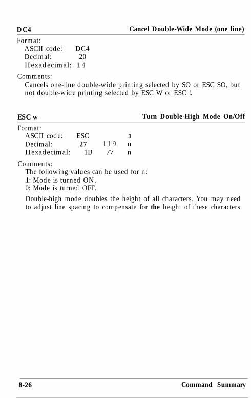
DC4 Cancel Double-Wide Mode (one line)
Format:ASCII code: DC4Decimal: 20Hexadecimal: 14
Comments:Cancels one-line double-wide printing selected by SO or ESC SO, butnot double-wide printing selected by ESC W or ESC !.
ESC w Turn Double-High Mode On/Off
Format:ASCII code: ESC nDecimal: 27 119 nHexadecimal: 1B 77 n
Comments:The following values can be used for n:1: Mode is turned ON.0: Mode is turned OFF.Double-high mode doubles the height of all characters. You may needto adjust line spacing to compensate for the height of these characters.
8-26 Command Summary

Print Enhancement
ESC r Select Printing Color
Format:ASCII code: ESC nDecimal: 27 114 nHexadecimal: 1B 72 n
Comments:The variable n selects the printing color according to the table below.n Color0 Black1 Magenta2 Cyan3 Violet4 Yellow5 Red6 Green
ESC E Select Emphasized Mode
Format:ASCII code: ESC EDecimal: 27 69Hexadecimal: 1B 45
Comments:Makes text bolder by printing each dot twice, with the second dotslightly to the right of the first.
ESC F Cancel Emphasized ModeFormat:
ASCII code: ESC FDecimal : 27 70Hexadecimal: 1B 46
Comments:Cancels emphasized, the mode selected by ESC E.
Command Summary 8-27

ESC G Select Double-Strike Mode
Format:ASCII code: ESC GDecimal: 27 71Hexadecimal: 1B 47
Comments:Makes text bolder by printing each line twice, with the secondprinting slightly below the first.
ESC H Cancel Double-Strike Mode
Format:ASCII code: ESC HDecimal: 27 72H e x a d e c i m a l : 1 B 4 8
Comments:Turns off the double-strike mode selected by ESC G.
ESC S Select Superscript/Subscript
Format:ASCII code: ESC S nDecimal: 27 83 nHexadecimal : 1B 53 n
Comments:Prints characters about two-thirds of the normal character heightin the upper (superscript.) or lower (subscript) part of thecharacter space. n = 0 selects superscript n = 1 selects subscript.
ESC T Cancel Superscript/SubscriptFormat:
ASCII code: ESC TDecimal: 78 54Hexadecimal : 1B 54
Comments:Cancels either superscript or subscript.
8-28 Command Summary

ESC - Turn Underlining Mode On/Off
Format:ASCII code: ESC - nDecimal: 27 45 nHexadecimal: 1B 2D n
Comments:n = 1: Mode is turned on. n = 0: Mode is turned off.This mode underlines spaces (but not tabs).
ESC qFormat:
ASCII code: ESC q nDecimal: 27 113 nHexadecimal: 1B 71 n
Comments:
Select Character Style
n = 0: Select normal style n = 2: Select shadow stylen = 1: Select outline style n = 3: Select outline with shadow
E S C ( - Select Score
Format:ASCII code: ESC ( - nl n2 m dl d2Decimal: 27 40 45 nl n2 m dl d2Hexidecimal: 1B 2B 2D nl n2 m dl d2
Comments:Use decimal or hexadecimal values, not ASCII characters, for allvariables. For the first three variables: nl must be 3, n2 must be 0,and m must be 1.
The value of dl determines the location of the score:1 = underline, 2 = strike-through, and 3 = overscore.
The value of d2 determines the line style:1 = single continuous,2 = double continuous,5 = single broken, and6 = double broken.d2 = 0 cancels the score line selected by dl .
Command Summary 8-29
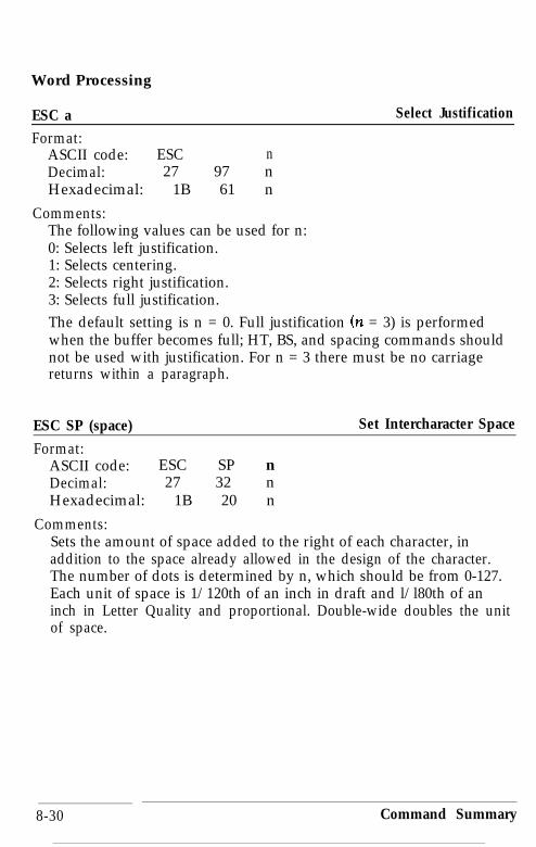
Word Processing
ESC aFormat:
ASCII code: ESC nDecimal: 27 97 nHexadecimal: 1B 61 n
Select Justification
Comments:The following values can be used for n:0: Selects left justification.1: Selects centering.2: Selects right justification.3: Selects full justification.The default setting is n = 0. Full justification (n = 3) is performedwhen the buffer becomes full; HT, BS, and spacing commands shouldnot be used with justification. For n = 3 there must be no carriagereturns within a paragraph.
ESC SP (space)Format:
ASCII code: ESC SP nDecimal: 27 32 nHexadecimal: 1B 20 n
Set Intercharacter Space
Comments:Sets the amount of space added to the right of each character, inaddition to the space already allowed in the design of the character.The number of dots is determined by n, which should be from 0-127.Each unit of space is 1/120th of an inch in draft and l/l80th of aninch in Letter Quality and proportional. Double-wide doubles the unitof space.
8-30 Command Summary
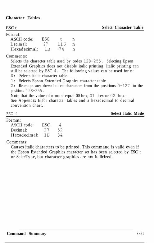
Character Tables
ESC tFormat:
ASCII code: ESC t nDecimal: 27 116 nHexadecimal: 1B 74 n
Select Character Table
Comments:Selects the character table used by codes 128-255. Selecting EpsonExtended Graphics does not disable italic printing. Italic printing canstill be selected by ESC 4. The following values can be used for n:0: Selects italic character table.1: Selects Epson Extended Graphics character table.2: Re-maps any downloaded characters from the positions 0-127 to thepositions 128-255.Note that the value of n must equal 00 hex, 01 hex or 02 hex.See Appendix B for character tables and a hexadecimal to decimalconversion chart.
ESC 4
Format:ASCII code: ESC 4Decimal: 27 52Hexadecimal: 1B 34
Select Italic Mode
Comments:Causes italic characters to be printed. This command is valid even ifthe Epson Extended Graphics character set has been selected by ESC tor SelecType, but character graphics are not italicized.
Command Summary 8-31
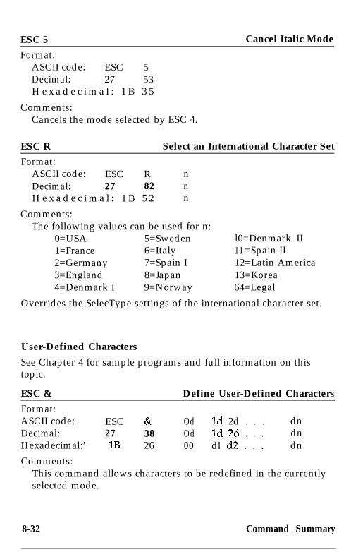
ESC 5 Cancel Italic Mode
Format:ASCII code: ESC 5Decimal: 27 53H e x a d e c i m a l : 1 B 3 5
Comments:Cancels the mode selected by ESC 4.
ESC R Select an International Character Set
Format:ASCII code: ESC R nDecimal: 27 82 nH e x a d e c i m a l : 1 B 5 2 n
Comments:The following values can be used for n:
0=USA 5=Sweden l0=Denmark II1=France 6=Italy 11 =Spain II2=Germany 7=Spain I 12=Latin America3=England 8=Japan 13=Korea4=Denmark I 9=Norway 64=Legal
Overrides the SelecType settings of the international character set.
User-Defined Characters
See Chapter 4 for sample programs and full information on thistopic.
ESC & Define User-Defined Characters
Format:ASCII code: ESC &Decimal: 27 38Hexadecimal:’ 1B 26
Comments:
Od Id 2d . . . dnOd Id 26 . . . dn00 dl 62 . . . dn
This command allows characters to be redefined in the currentlyselected mode.
8-32 Command Summary

ESC : Copy ROM into RAM
Format:ASCII code: ESC : 0 n 0Decimal: 27 58 0 n 0Hexadecimal: 1B 3A 00 n 00
Comments:This code copies the characters in the ROM into RAM so thatspecific characters can be redefined. Orator and Orator-S are onlyavailable with the Multi-Font Module. The variable n representsthe font family as follows.0: Roman 5: OCR-B1: Sans Serif 6: OCR-A2: Courier3: Prestige4: Script
ESC %Format:
ASCII code: ESC % nDecimal: 27 37 nHexadecimal: 1B 25 n
Select User-Defined Set
Comments:ESC & is required to first define the character set. The followingvalues can be used for n:0: Selects the normal set.1: Selects the user-defined set.
ESC 6 Enable Printable Characters
Format:ASCII code: ESC 6Decimal: 27 54H e x a d e c i m a l : 1 B 3 6
Comments:When the Epson Extended Graphics character table is selected,this code enables the printing of codes 128 through 159 (decimal)as characters, not control codes.
Command Summary 8-33

ESC 7Format:
ASCII code: ESC 7Decimal: 27 55Hexadecimal: 1B 37
Enable Upper Control Codes
Comments:When the Epson Extended Graphics character table is selected, thiscode causes codes 128 through 159 to be treated as control codes. Thisis the default.
Graphics
See Chapter 4 for sample graphics programs. See the table under ESC *for graphics modes.
ESC K Select Single-Density Graphics Mode
Format:ASCII code: ESC K nl n2Decimal : 27 75 nl n2Hexadecimal: 1B 4B nl n.2
Comments:Turns on 8-pin, single-density graphics mode. The total number ofcolumns = n7 + (n.2 X 256).
ESC L Select Double-Density Graphics Mode
Format:ASCII code: ESC L n7 n2Decimal: 27 76 nl n2Hexadecimal: 1B 4C nl n2
Comments:Turns on 8-pin, low-speed, double-density graphics mode. The totalnumber of columns = nl + (n2 X 256).
8-34 Command Summary
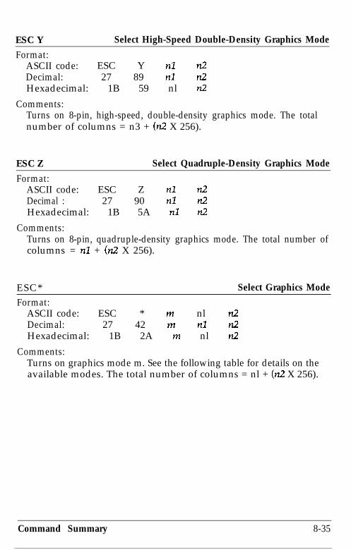
ESC Y Select High-Speed Double-Density Graphics Mode
Format:ASCII code: ESC Y nl n2Decimal: 27 89 nl n2Hexadecimal: 1B 59 nl n2
Comments:Turns on 8-pin, high-speed, double-density graphics mode. The totalnumber of columns = n3 + (n2 X 256).
ESC Z Select Quadruple-Density Graphics Mode
Format:ASCII code: ESC Z nl n.2Decimal : 27 90 nl L!Hexadecimal: 1B 5A nl n2
Comments:Turns on 8-pin, quadruple-density graphics mode. The total number ofcolumns = n7 + (n2 X 256).
ESC* Select Graphics ModeFormat:
ASCII code: ESC * m nl a2Decimal: 27 42 m nl n2Hexadecimal: 1B 2A m nl n.2
Comments:Turns on graphics mode m. See the following table for details on theavailable modes. The total number of columns = nl + (n2 X 256).
Command Summary 8-35

Option Pins mHoriz. density]
Single-densityDouble-densitvHigh-speed dduble-density*Q-&uple-density*
CRT IISingle-densityDouble-densityCRT IITriple-densityHex-density*Adjacent dots cannot be printed in this mode.
24
;t
0
:3
i
i23383940
::120
90180360
ESC ?Format:
ASCII code: ESC ? s mDecimal: 27 63 s mHexadecimal: 1B 3F s m
Comments:
Reassign Graphics Mode
Changes one graphics mode to another. The variable s is a graphicsmode defined by the character K, L, Y, or Z, which is reassigned to amode m (O-6).
Command Summary

Appendix A
Technical Specifications
Printer Specifications . . . . . . . . . . . . . . . . . . . . . . . . . . . . . . . . . . . . . . . . A-2
Double-Bin Cut Sheet Feeder Specifications . . . . . . . . . . . . . . . . . . . . . A-6
Interface Specifications . . . . . . . . . . . . . . . . . . . . . . . . . . . . . . . . . . . . . . A-9
Initialization . . . . . . . . . . . . . . . . . . . . . . . . . . . . . . . . . . . . . . . . . . . . . . A-13
Default Settings . . . . . . . . . . . . . . . . . . . . . . . . . . . . . . . . . . . . . . . . . . . A-14
Technical Specifications A-l

Printer Specifications
Printing
Print method: 24pin impact dot matrix
Print speed: See table below.
Quality CPI Characters/second/lineDraft 10 333
12 400LQ 10 111
12 133
Printing direction: Bidirectional logic-seeking for text andgraphics. Unidirectional available throughSelecType or software command.
Line spacing: l/6”, l/8”, or programmable in increments of1/60th, l/180th or 1/360th of an inch
Paper feed speed: 83 ms/line at l/6” line spacing
Printable columns: See table below.
Character size1Ocpi10cpicondensed12cpi12 cbcondensed
Maximum printed characters136233163272
A-2 Technical Specifications

Character fonts:
1 Font 1 Available Sizes (characters per inch)Epson Draft
Epson Roman
Eoson Sans Serif
1 Ewon Courier
Epson Prestige
Epson Script
EDson OCR-A
Epson OCR-B
Epson ORATOR
Epson ORATOR-S
10,12,15
10,12,15, Proportional
10.12.15. ProDoftional
I 10,12,15, Proportional
IO,1 2,15, Proportional10,12,15, Proportional
10.12. ProDortional
IO,1 2, Proportional
IO (Optional)
10 (Optional)
Characters: 96 standard ASCII character set(including italic characters)13 international character setsEpson Extended Graphics characters
Paper feed methods: FrictionBuilt-in push feed tractorPull tractor (optional)Double-bin cut sheet feeder (optional)
Paper width:
Paper length:
Single sheets7.15 to 14.3 inches (182 to 364 mm)
Continuous4.0 to 16.0 inches (101 to 406 mm)
EnvelopeNo. 6 (166 x 92 mm),No. 10 (240 x 104 mm)
Label2-l/2 15/16 inches,4 15/16 inches,4 l-7/16 inches,
Single sheets7.2 to 14.3 inches (182 to 364 mm)
Technical Specifications

Paper thickness: Single sheets0.0026 to 0.004 inches (0.065 to 0.1 mm)
Continuous0.0023 to 0.018 inches (0.06 to 0.46 mm)
Envelope0.0063 to 0.0197 inches (0.16 to 0.52 mm)
Label0.0075 inches (maximum 0.19 mm)
Printable area:
Single sheet
m 4.5 mm (0.33 “) or more
-3 mm (0.12”)or more
9 mm (0.35”)or more
:
Continuous paper
101 to 381 mm (4.0 to 15.0”) paper widthI I
13.5 mm (0.53”) or more13 mm (0.51”) or more406 mm (16.0”) paper width26 mm (1.02”) or more
*For printable area for envelopes, see page A-8.
Number of copies: Continuous, multi-part, no carbon: oneoriginal plus up to five copies. Total thicknessmust not exceed 0.018” (0.46 mm)
A-4 Technical Specifications

Ribbon:
MCBF:
MTBF:
Print head life:
Dimensions and weight:
Voltage:
Power consumption:
Frequency:
Insulation resistance:
Black ribbon cartridge #7762:Life expectancy (in Letter Qualitycharacters, at 48 dots/character): 3 million
Color ribbon cartridge #7763:Life expectancy (in Letter Qualitycharacters, at 48 dots/character)
Black: 1.0 millionCyan: 0.7 millionMagenta: 0.7 millionYellow 0.5 million
Film ribbon cartridge #7764:Life expectancy (at 10 cpi, with bi-directional printing, using 136 columns):0.1 million** This number may vary depending on
print direction, characters per inch, ortext density per page.
For all components excluding print head:5 million lines
6000 power-on hours (at 25% duty)
200 million strokes per wire
Height: 7.7”Width: 26.6"Depth: 20.4"Weight : approx. 44 lbs
120 VAC f 10%
400 watts maximum
49.5 to 60.5 Hz
10M ohms between AC power line and chassis
Dielectric strength (between AC line and chassis):Can withstand 1.00 kV rms applied for oneminute or 1.2 kV rms applied for one second.
Technical Specifications A-5

Temperature:
Humidity:
Operation: 40°F to 95°F (ST to 35°C)Storage: -22°F to 140°F (-30°C to 60°C)
Operation: 10% to 80% (withoutcondensation)Storage: 5% to 85% (without condensation)
Shock: Operation: Up to 1 G within 1 msStorage: Up to 2 G within 1 ms
Vibration: Operation: Up to 0.25 G at up to 55 HzStorage: Up to 0.50 G at up to 55 Hz
Double-Bin Cut Sheet Feeder (Optional)Dimensions and weight: 26.7”(W) X 22.9”(D) x 16.5”(H)
(mounted on the printer)approx. 13.2 lbs.
Bin capacity:bin 1Single sheets: Up to 150 sheets of 22 lb. paper
Up to 185 sheets of 17 lb. paper(Total thickness should notexceed 0.59” or 15mm)
Envelopes* : Up to 25 (plain and bond type)Up to 30 (air mail)
bin 2Single sheets: Up to 150 sheets of 22 lb. paper
Up to 185 sheets of 17 lb. paper(Total thickness should not exceed 0.59” or15mm)
* Envelopes can only be used in bin 1.
A-6 Technical Specifications
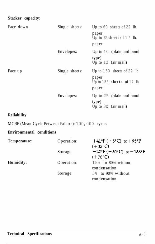
Stacker capacity:
Face down Single sheets:
Face up Single sheets:
Envelopes:
Envelopes:
Reliability
Up to 60 sheets of 22 lb.paperUp to 75 sheets of 17 lb.paper
Up to 10 (plain and bondtype)Up to 12 (air mail)
Up to 150 sheets of 22 lb.paperUp to 185 sheets of 17 lb.paper
Up to 25 (plain and bondtype)Up to 30 (air mail)
MCBF (Mean Cycle Between Failure): 100,000 cycles
Environmental conditions
Temperature:
Humidity:
Operation:
Storage:
Operation:
Storage:
+41"F(+5"C) to +95”F(+35"(z)-22"F(-30°C) to +158"F(+7o"c)15% to 80% withoutcondensation5% to 90% withoutcondensation
Technical Specifications A-7
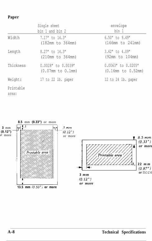
Paper
Width
Length
Thickness
Weight:
Printablearea:
Single sheet envelopebin 1 and bin 2 bin 1
7.17” to 14.3” 6.50” to 9.49”(182mm to 364mm) (166mm to 241mm)
8.27” to 14.3” 3.62” to 4.09”(210mm to 364mm) (92mm to 104mm)
0.0028” to 0.0039” 0.0063” to 0.0205”(0.07mm to O.lmm) (0.16mm to 0.52mm)
17 to 22 lb. paper 12 to 24 lb. paper
8.5 mm (0.33”) or more
3 mm(0 .12”)
)r more or more
13.5 mm /0.53”J or more
Tor more
I , 2 2 m mIt
3 mm(0.12”!or more
1 (0.87”)or more
A-8 Technical Specifications

Storage condition:Temperature:
Humidity:
+64”F (+lB”C) to 72°F(+22”c)40% to 60%
Interface SpecificationsYour printer is equipped with both a parallel and a serial interface. Forspecifications for optional interfaces, see the manuals provided with theoptional interfaces.
Parallel interfaceThe following tables describe the parallel interface.
Pin assignments for the parallel interface
Connector pin assignments and a description of their respective interfacesignals are shown in the following table.
when data is logical 1 and LOW when it is
BUSY
and that the printer is ready to acceptmore data.
OUT A HIGH signal indicates that the printercannot receive data. The signal goesHIGH in the following cases:1) During data entry (ea. char. time)2) During printing3) When off line4) During printer-error state.
Technical Specifications A-9

CHASSIS GND
32 - ERROR
33 - GND34 - NC35 - -
s LOW, the printercontroller is reset to its power-up stateand the print buffer is cleared. This levelis usually HIGH; its pulse width must bemore than 50 microseconds at thereceiving terminal.
OUT zis level becomes LOW when the printer
1) in paper-out state2) off line3) in error state.
- Same as for Pins 19 - 30.- Not used.
OUT Pulled up to 5V through 3.3K ohmresistance.
36 - SLCT IN lN The DClIDC3 code is valid only when thissignal is “HIGH”.
&Yhe same effect can
be achieved with elecType.)
l The column heading “Direction” refers to the direction of signal flowas viewed from the printer.
0 “Return” denotes the twisted-pair return, to be connected at signalground level. For the interface wiring, be sure to use a twisted-paircable for each signal and to complete the connection on the returnside. These cables should be shielded and connected to the chassis ofthe host computer and the printer.
A-10 Technical Specifications

l All interface conditions are based on TTL level. Both the rise and thefall times of each signal must be less than 0.2 microseconds.
l Data transfer must be carried out by observing the ACKNLG orBUSY signal. Data transfer to this printer can be carried out onlyafter receipt of the ACKNLG signal or when the level of the BUSYsignal is LOW.
Printing enabled/disabled signals and control conditions
The following table shows the relationship between printing beingenabled or disabled, the on line/off line status, and the receipt of the dataon/off control characters, DC1 or DC3.
ON LINE SLCT IN DClIDC3 ERROR BUSYtt$icator (Data
on/offcontrol)
ACKNLG Printing(Disabled/enabled)
on line High DC1 High High/Low Pulsed EnabledRecv’d ea. char.
on line High DC3 High High/Low Pulsed Disabled’Recv’d ea. char.
off line High/Low DC1 /DC3 Low High Not Disabled(no effect) (no effect) generated
*While printing is disabled, character data is being received andacknowledged so that the printer can look for another DC1 character,which would allow it to resume printing.
Technical Specifications A-11

Interface timingThe figure below shows the timing for the parallel interface.
BUSY f-4ACKNLG I
DA TASTROBE
Serial interface
The LQ built-in serial interface is an RS-232C asynchronous interfacewith the following characteristics:
Data format
1 start bitData word length: 8 bitOdd, even, or no parity1 stop bit
Baud rate
300, 600, 1200, 2400, 4800, 9600,192OO bits per second.
Signal level
Mark (1) -3 V to -27 VSpace (0) +3 V to +27 V
A-12 Technical Specifications

Handshaking
Handshaking by DTR signal or X-on/X-off. The DTR signal changes tomark - meaning the printer is not ready to receive data - when thenumber of bytes free in the input buffer goes down to 256. The signalchanges to space - meaning that the printer is now ready - when thenumber of bytes in the input buffer rises to 528.
Error handling
A * character is printed if a parity error is detected. All other errors areignored.
Connector
D-sub 25-pin connector
In this table, the direction of signals is given relative to the printer.
InitializationThere are the three ways that the printer can be initialized (returned to afixed set of conditions).
Hardware initialization l When the power is turned on
l When the printer receives an INITsignal at the parallel interface (pin 31goes LOW).
Software initialization l Software sends the ESC @ (initializethe printer) command.
Technical Specifications A-13
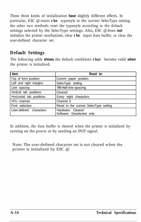
These three kinds of initialization have slightly different effects. Inparticular, ESC @ resets the typestyle to the current SelecType setting;the other two methods reset the typestyle according to the defaultsettings selected by the SelecType settings. Also, ESC @ does notinitialize the printer mechanism, clear the input data buffer, or clear theuser-defined character set.
Default SettingsThe following table shows the default conditions that become valid whenthe printer is initialized.
I Item I Reset to: ITop of form positionLeft and right marginsLine spacingVertical tab positionsHorizontal tab positionsVFU channelFont selectionUser-defined characters
Current paper positionSelecType settingl/6-inch line spacingClearedEvery eight charactersChannel 0Reset to the current SelecType settingHardware: ClearedSoftware: Deselected only
In addition, the data buffer is cleared when the printer is initialized byturning on the power or by sending an INIT signal.
Note: The user-defined character set is not cleared when theprinter is initialized by ESC @.
A-14 Technical Specifications
Appendix B
Proportional Width Table . . . . . . . . . . . . . . . . . . . . . . . . . . . . . . . . . . . . B-2Character Tables . . . . . . . . . . . . . . . . . . . . . . . . . . . . . . . . . . . . . . . . . . . . B-6
Converting hexadecimal numbers to decimal . . . . . . . . . . . . . . . . . . B-8
Appendix B B-1
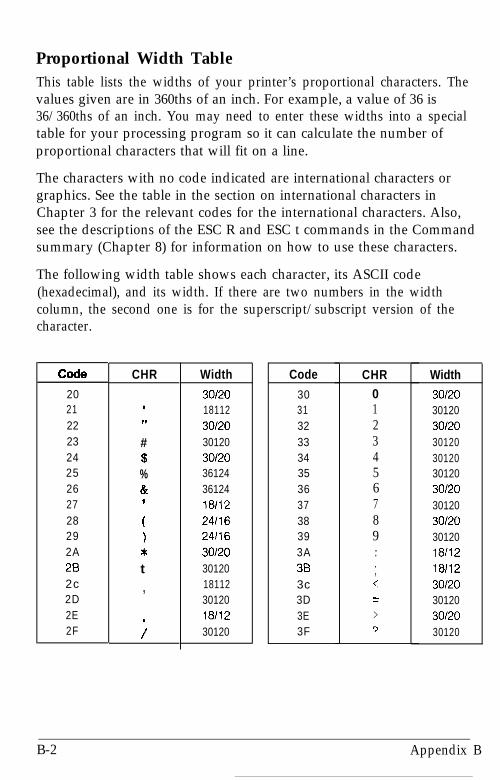
Proportional Width TableThis table lists the widths of your printer’s proportional characters. Thevalues given are in 360ths of an inch. For example, a value of 36 is36/360ths of an inch. You may need to enter these widths into a specialtable for your processing program so it can calculate the number ofproportional characters that will fit on a line.
The characters with no code indicated are international characters orgraphics. See the table in the section on international characters inChapter 3 for the relevant codes for the international characters. Also,see the descriptions of the ESC R and ESC t commands in the Commandsummary (Chapter 8) for information on how to use these characters.
The following width table shows each character, its ASCII code(hexadecimal), and its width. If there are two numbers in the widthcolumn, the second one is for the superscript/subscript version of thecharacter.
CO&
202122232425262728292A282c2D2E2F
CHR
II,
#$%&
;)*t,
i
Width Code
30120 3018112 3130120 3230120 3330120 3436124 3536124 3618112 3724116 3824116 3930120 3A30120 3818112 3c30120 3D18112 3E30120 3F
CHR0123456789...,c=>3
Width
30120301203012030120301203012030120301203012030120181121811230120301203012030120
B-2 Appendix B

1 Code 1 CHR40 @41 A42 B43 c44 D45 E46 F47 G48 H49 I
4A J48 K4c L4D M4E N4F 05051 2;52 R53 S54 T55 U56 v57 W58 X59 Y5A z5B5c :5D 1h5E5F6061
T
a
Width
36124361243612436124361243612436124361243612424116301203612436124421283612436124361243612436124361243612442128361244212836124361243012024116301202411630120301201811230120
Code6465666768696A6B6C6D6E6F707172737475767778797A78
7c7D7E
CHRdef?I
iii
1mn0
PclrS
tU
V
W
x
Y
?
i
ci i6.i66.
itcG
Width
3612430120241163612436124181122411636124181124212836124301203612436124301203012024116361243612442128301203612430120241161811224116301203612436124301203012030120
30120 301203012030120
Appendix B B-3

Width
30120301201811218112181123612436124361244212842128301203012030120361243612436124361244212830120301203612442128301203012018112301203612436124361243012030120301203012030120301203012030120
Code
B OBl82838485B68788B9BABBBcBDBEBFcoClc2c3c4c5C6c7C8c9CACBc cCDCECFDODlD2
Width
30120301203030303030303030303030303030303030303030303030303030303030303030303030
B-4 Appendix B
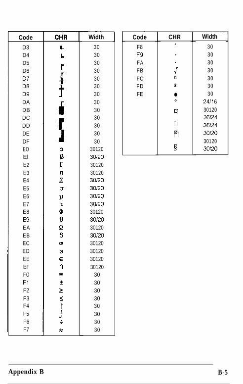
Code
D3D4D5D607DBD9DADBDCDDDEDFEOElE2E3E4E5E6E7E8E9EAEBECEDEEEFFOFlF2F3F4F5F6F7
Width
30303030303030303030303030
301203012030120301203012030/2030120301203012030120301203012030120301203012030120
3030303030303030
Code
F8F9FAFBFCFDFE
CHR0
.
;n
2
l0
#
00. .
§
Width
30303030303030
24/l 6301203612436124301203012030120
Appendix B B-5

Character TablesThese character tables are selected by SelecType or the ESC t softwarecommand. For the Epson Extended Graphics character table, the ESC 6or ESC 7 software command lets you select whether to print hex codes80 to 9F as characters (ESC 6) or control codes (ESC 7).
Italic Character Table
:ODE 0 1 2 3 4 5 6 7 6 9 A B C D E F
0 0 @ P c p O@P(P1 I.lAQaq . 1 -4 Q a q,
1,2 11 2 B R b r 2Bf?br3 #3CScs 79 .? c- s c s4 $qDTdt SlDTdt5 % 5 E U e u % 5 E Cl e tl6 & 6 F V f \7 g. 6 F I/ f I'
,7 7 G W g w t 7 G l-4 g TV'8 (8~Xhx ( 8 H -I- h s9 19TYiy ) 9 T Y i J-A * : J Z j z * : J Z jzB t ;K [ k { + ;k'r k{C , < L \lI 9 < I. 1 1 'D - = Y 1 m =E > N h n
1 Y+nic.F ; ? o - o / r: ‘E - :
B-6 Appendix B

Epson Extended Graphics Character Table
ZODE
0123456789ABCDEF
0 1 2 3 4 5 6 7 6 9 A B C D E F
O@P' p c B B L Y a zt;I 1 A Q a q ii ap i
ZBRbr&iE6P3CScs~66
Appendix B B-7

Converting hexadecimal numbers to decimal numbersIf you prefer to use decimal numbers instead of hexadecimal numbers,you can convert them with the chart below. Just read down in thecolumn for the first digit of the hex number and across in the row for thesecond digit. Where the two intersect is the decimal number thatcorresponds to your hex number. For example, to find the decimalequivalent of hex 5A, look where column 5 intersects with row A, Thereyou will find decimal 90.
Hex-to-Decimal Conversion Chart
CODElO123456769ABCDEF
0 0 16 32 48 64 80 96 112 128 144 160 176 192 208 224 2401 1 17 33 49 65 81 97 113 129 145 161 177 193 209 225 2412 2 18 34 50 66 82 98 114 130 146 162 178 194 210 226 2423 3 19 35 51 67 83 99 115 131 147 163 179 195 211 227 2434 4 20 36 52 68 84 100 116 132 148 164 180 196 212 228 2445 5 21 37 53 69 85 101 117 133 149 165 181 197 213 229 2456 6 22 38 54 70 86 102 118 134 150 166 182 198 214 230 2467 7 23 39 55 71 87 103 119 135 151 167 183 199 215 231 2476 8 24 40 56 72 88 104 120 136 152 168 184 200 216 232 2489 9 25 41 57 73 89 105 121 137 153 169 185 201 217 233 249A 10 26 42 58 74 90 106 122 138 154 170 186 202 218 234 250B 11 27 43 59 75 91 107 123 139 155 171 187 203 219 235 251C 12 28 44 60 76 92 108 124 140 156 172 188 204 220 236 252D 13 29 45 61 77 93 109 125 141 157 173 189 205 221 237 253E 14 30 46 62 78 94 110 126 142 158 174 190 206 222 238 254F 15 31 47 63 79 95 111 127 143 159 175 191 207 223 239 255
B-8 Appendix B

Glossary
Note that these definitions apply specifically to printers. If a word isitalicized, see that topic for more information.
application programA program that helps you carry out a particular task, such as wordprocessing or financial planning.
ASCIIAmerican Standard Code for Information Interchange. A standardizedcoding system for assigning numerical codes to letters and symbols.
automatic line feedWhen this feature is turned on using SelecType, each carriage returncode (CR) is automatically accompanied by a line feed (LF) code.
baud rateA measure of the speed of data transmission. Usually equivalent to bitsper second.
bidirectional printingPrinting in which the print head moves in alternate directions on everyother line. This increases the speed of printing because the head prints inboth directions.
binarySee number systems.
bitA binary digit (0 or l), which is the smallest unit of information used bya printer or computer. See also number systems,
bufferSee memory.
byteA unit of information consisting of eight bits.
Glossary GL-1

carriage returnThe control code that returns the print position to the left margin. Whenissued together with a line feed, the print position moves to the leftmargin of the next line. In bidirectional printing, the print head may notactually move to the left margin.
characters per inch (cpi)A measure of the size of text characters, often referred to as pitch. 10 cpi(also called pica) is often the standard or default setting.
condensedPrinting in which each character is approximately 60% of the width ofstandard characters. Useful for fitting wide tables or spreadsheets ontothe paper.
continuous paperPaper that has sprocket-feed holes on each side, is perforated betweenpages, and comes in a folded stack. Also called fanfold paper.
control codeBesides the codes for printable characters, the ASCII standard alsoincludes 33 other codes called control codes. These control codes performsuch functions as sounding the beeper and performing a carriage returnor line feed.
cut sheet feeder (CSF)An optional, detachable device that automatically feeds single sheets ofpaper into the printer.
data dumpA troubleshooting feature. When the printer is in data dump mode, eachcode that it receives is printed in hexadecimal notation as well as theASCII codes that stand for the characters. Sometimes called hex dump.
decimalSee number systems.
defaultA value or setting that takes effect when the equipment is turned on,reset, or initialized.
GL-2 Glossary

dot graphicsA graphic design formed by patterns of dots.
dot matrixA method of printing in which each letter or symbol is formed by apattern (matrix) of individual dots.
double-high printingPrinting in which each character is twice as high as normal.
double-strike printingA way of producing bolder characters. Each character is printed twice;the second time, the dots are printed slightly below the original dots.
double-wide printingA print width in which each character is twice as wide as normalcharacters.
draftOne of two print qualities available on your printer. Draft uses aminimum number of dots per character for high-speed printing. See alsoLetter Quality.
emphasized printingA way of producing darker characters. Each character is printed twice,with the second slightly to the right of the first.
Epson Extended GraphicsThe Epson Extended Graphics character table contains internationalaccented characters, Greek characters, and character graphics forprinting lines, comers, and shaded areas.
ESC (escape)A special control code used to begin most printer commands.
ESC/PAbbreviation for Epson Standard Code for Printers. The system ofcommands lets you control your printer using your computer’s software.It is standard for all Epson printers and supported by most applicationssoftware for personal computers.
fontA style of type designated by a family name.
Glossary GL-3

formIn printer terminology, a form is normally the equivalent of a page.
form feedA control code and a control panel button that advances the paper to thetop of the next form.
hexadecimal (hex)See number systems.
initializeTo establish the initial default status of the printer by turning the printeron, sending ESC @, or sending an INIT signal.
interfaceThe connection between the computer and the printer. A parallelinterface transmits data one character or code at a time, and a serialinterface transmits data one bit at a time.
italicA typestyle in which the characters slant. This sentence is italicized.
Letter Quality (LQ)One of two print qualities available on your printer. Letter Qualityreduces the print speed and increases the number of dots per character toincrease the print quality. See also draft.
line feedA control code and a control panel button that advances the paper oneline space.
memoryThe printer, like a computer, has a memory. When you print a file from acomputer, the contents of the file are transferred quickly from thecomputer’s memory to the printer’s memory The printer then printsinformation from its own memory at a much slower rate. This way ofprinting frees the computer to do other work while the printer is stillworking. The printer memory is sometimes called the buffer.
micro-adjustmentA feature that adjusts the paper loading and tear-off positions.
GL-4 Glossary

number systemsThree number systems are commonly used with printers:
decimal is base 10 and uses the digits 0, 1, 2, 3, 4, 5, 6, 7, 8, and 9.(This is the most familiar system.)
hexadecimal (hex) is base 16 and uses the digits 0, 1, 2, 3, 4, 5, 6, 7, 8,9, A, B, C, D, E, and F. This is frequently used by programmers. Anydecimal number between 0 and 255 can be expressed by a two-digithex number.
binary is base 2 and uses only the digits 0 and 1. All information incomputer systems is handled in binary form to represent electricalsignals that are on or off. A binary digit is often called a bit; anydecimal number between 0 and 255 can be expressed by an eight-bitbinary number.
on lineWhen the printer is on line, it can communicate with the computerconnected to it.
parallel interfaceSee inferface.
parityParity is a method for a computer and printer to check the reliability ofdata transmission.
platenThe black roller that provides a backing for the printing.
print qualityYour printer has two types of print quality: draft and Letter Quality(LQ). Draft is for high-speed, draft-quality jobs; LQ is for final, polisheddocuments.
proportional printingPrinting in which the width of the character varies from character tocharacter. For example, an uppercase W receives much more space thana lowercase i. The result looks more like a typeset book than atypewritten draft.
Glossary GL-5

push tractorThe built-in device that feeds continuous paper through the printer.
Random Access Memory. The portion of the printer’s memory used as abuffer and for storing user-defined characters. All data stored in RAM islost when the printer is turned off.
resetTo return a printer to its defaults, by either a command, an INIT signal,or by turning the printer off and on.
self testA method of checking the operation of the printer. When the self test isrun, the printer prints out its current SelecType settings and thecharacters that are stored in its ROM.
serial interfaceSee interface.
short tear-offA feature that automatically feeds the perforation of continuous paper tothe tear-off position and then feeds the paper back to the loadingposition. This position can be adjusted by using the micro-adjustmentfeature.
top of form positionThe position on the paper that the printer recognizes as the first printableline.
userdefined charactersCharacters that are defined and stored in the printer by the user. Alsoknown as download characters.
GL-6 Glossary

Index
Command descriptions are not indexed here. For page references forspecific commands, see Chapter 8 or the Quick Reference card.
AApplication software. See SoftwareASCII codes, 4-5, 8-l--36, Quick
ReferenceAssembling the printer, l-7--15Auto line feed, selecting with
SelecType, 3-18-22Auto tear off. See short tear-off
BBaud rate, setting with SelecType,
3-18-22Buttons. See Control panel, buttons
CCHANGE DEFAULTS mode,
3-18-22CHANGE MACRO mode, 3-15-18Character set, 3-15-18, 3-39Character size. See PitchCharacter tables, 3-15--18,
3-40-41, B-6--7Character pitch. See PitchCharacters per inch (cpi). See PitchCleaning printer, 5-2-3CLEAR ALL MACROS mode,
3-24-26
Codes. See ASCII codes, Commands,Control codes
Colorgraphics, 4-14selecting with SelecType,3-15-18
Command Summary, 8-l--36using, 4-7
Commands, 4-6-7, 8-l--36, QuickReferenceby topic, 8-8-36in numerical order, 8-5-7
Communication. SeeComputer-printer communication
Computercomputer-printer communication,4 - 5 - 7connecting to the printer,1-22--27
Computer-printer communicationASCII codes, 4-5control codes, 4-5escape sequences, 4-6printer commands, 4-6-7. Seealso Commandsusing the Command Summary,4-7
Condensed mode. See TypestylesContinuous paper
loading, 2-6-13positioning, 2-5-6printable area, A-4reversing to standby position,2-14-15tearing off, 2-13--14. See alsoShort tear-offusing, 2-5-22
Control codes, 4-5, 8-1-36, QuickReference
Index-l

Control panel, 3-2--8buttons, 3-4--7data dump, 3-8display, 3-2lights, 3-3--4SelecType. See SelecTypeself test, 3-8. See also Self test
Conventions, 4Country. See character setCourier. See Typestyles, fontsCut sheet feeder, 7-2-21
installing, 7-2-6loading paper, 7-6-9, 7-11--13,7-18-19removing, 7-20--21testing, 7-9--11using, 7-13--16
DData dump mode, 6-6Default macro, selecting with
SelecType, 3-18--22Default settings, A-14. See also
SelecTypeDisplay. See Control panel, display
and SelecTypeDouble-high printing, 4-9Double-strike printing, 4-9--10Double-wide printing, 4-9Draft. See Typestyles, fonts
EEmphasized printing, 4-9--10Envelopes, 2-26--27
loading, 2-26--27loading in cut sheet feeder,7-11--13printable area, 2-27specifications. See Paper,specifications
Escape sequences, 4-6, 8-1-36,Quick Reference
FFeatures, list of, 1-2Fonts. See TypestylesForm length. See Page lengthFriction. See Paper select
GGraphics, 4-4-5, 4-12--23
color, 4-1424-pin, 4-15
HHex-to-decimal conversion, B-8
IIndicator lights. See Control panel,
lightsInitialization, A-13--14Installing the platen knob, 1-7--8Installing the paper guide, 1-12--15Installing the ribbon cartridge,
1-9--12Interface boards, optional, 7-33--45
choosing, 7-33--34compatibility, 7-33--34installing, 7-34--45Also see Parallel interface andSerial interface
Interfaces. See Interface boards,Parallel interface, Serial interface
International character set. SeeCharacter set
Italic printing, 4-10
Index-2
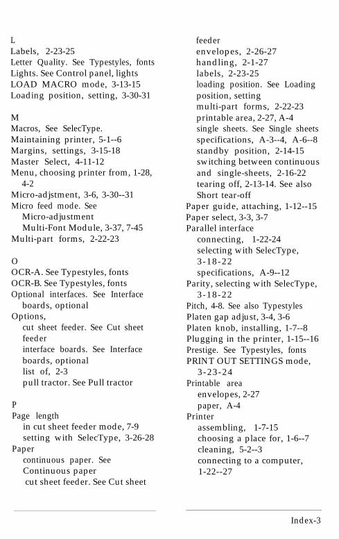
LLabels, 2-23-25Letter Quality. See Typestyles, fontsLights. See Control panel, lightsLOAD MACRO mode, 3-13-15Loading position, setting, 3-30-31
MMacros, See SelecType.Maintaining printer, 5-1--6Margins, settings, 3-15-18Master Select, 4-11-12Menu, choosing printer from, 1-28,
4-2Micro-adjstment, 3-6, 3-30--31Micro feed mode. See
Micro-adjustmentMulti-Font Module, 3-37, 7-45
Multi-part forms, 2-22-23
OOCR-A. See Typestyles, fontsOCR-B. See Typestyles, fontsOptional interfaces. See Interface
boards, optionalOptions,
cut sheet feeder. See Cut sheetfeederinterface boards. See Interfaceboards, optionallist of, 2-3pull tractor. See Pull tractor
PPage length
in cut sheet feeder mode, 7-9setting with SelecType, 3-26-28
Papercontinuous paper. SeeContinuous papercut sheet feeder. See Cut sheet
feederenvelopes, 2-26-27handling, 2-1-27labels, 2-23-25loading position. See Loadingposition, settingmulti-part forms, 2-22-23printable area, 2-27, A-4single sheets. See Single sheetsspecifications, A-3--4, A-6--8standby position, 2-14-15switching between continuousand single-sheets, 2-16-22tearing off, 2-13-14. See alsoShort tear-off
Paper guide, attaching, 1-12--15Paper select, 3-3, 3-7Parallel interface
connecting, 1-22-24selecting with SelecType,3-18-22specifications, A-9--12
Parity, selecting with SelecType,3-18-22
Pitch, 4-8. See also TypestylesPlaten gap adjust, 3-4, 3-6Platen knob, installing, 1-7--8Plugging in the printer, 1-15--16Prestige. See Typestyles, fontsPRINT OUT SETTINGS mode,
3-23-24Printable area
envelopes, 2-27paper, A-4
Printerassembling, 1-7-15choosing a place for, 1-6--7cleaning, 5-2--3connecting to a computer,1-22--27
Index-3

connecting to a power supply,1-15--16options. See Optionssetting up, 1-1--28testing, 1-15--21transporting, 5-7--9troubleshooting, 6-1--6unpacking, 1-2--5
Printer commands. See CommandsPrinting
direction, 3-15--18Double-high, 4-9Double-strike, 4-9--10Double-wide, 4-9Emphasized, 4-9--10enhancing, 4-7-12Italics, 4-10Subscripts, 4-10Superscripts, 4-10Underlining, 4-10
Problems and solutions, 6-2-5Proportional width table, B-2--5Protective materials, removing,
1-2--5Pull tractor, 7-21-32
installing, 7-21-24loading paper, 7-24-31removing, 7-31-32
RReplacing ribbon cartridge, 5-3-6Ribbon cartridge
installing, 1-9-12replacing, 5-3-6
Roman. See Typestyles, fonts
SSans Serif. See Typestyles, fontsScript. See Typestyles, fontsSelectype
arrow icons, 3-12CLEAR ALL MACROS,3-24-26CHANGE DEFAULTS, 3-18-22CHANGE MACRO, 3-15--18LOAD MACRO, 3-13--15PRINT OUT SETTINGS,3-23--24selecting a main menu mode,3-12--13using, 3-10--12
Self testin cut sheet feeder mode, 7-9--11running, 1-15-21
Serial interfaceconnecting, 1-24--27selecting with SelecType,3-18-22specifications, A-12--13
Setting up the printer, 1-1--28Short tear-off, 3-31--33Single sheets
loading, 2-2-5printable area, A-4reloading during printing, 2-5switching from continuous paper,2-16-22using, 2-2-5
Skip over perforation, 3-28-29Software
computer-printercommunications, 4-5-7graphics, 4-4--5. See alsoGraphicsprinter selection menus, 1-28, 4-2sending printer commands,
Index-4

4-5--7, 8-1--36setting up, 1-27--28spread sheets, 4-3-4using with the LQ-2550, 4-2--5word processors, 4-3
Specifications,cut sheet feeder, A-6--9default settings, A-14initialization, A-13--14interface, A-9--13paper, A-3--4, A-6--8printer, A-2--6
Subscripts, 4-10Superscripts, 4-10
TTables, B-l--8
character, B-6--7hex-to-decimal conversion, B-8proportional width, B-2--5
Tear off. See short tear-offTesting the printer, 1-15--21
in cut sheet feeder mode, 7-9--11Tractor. See Paper selectTransporting printer, 5-7--9Troubleshooting, 6-1--6Typestyles. See also Printing
condensed mode, 3-15--18,3-38--39, 4-8--9, 4-11--12
fonts, 3-15--18, 3-33--37pitch, 3-15--18, 3-33--34,3-37--38,4-8proportional mode, 3-15--18,3-37--38, 4-8, 4-11--12selecting with control panel,3-33--39selecting with Master Select,4-11--12selecting with SelecType,3-15--18special effects, 4-7--12
UUnderlining, 4-10Unpacking the printer, l-2--5
removing protective materials,l-2--5
User-defined characters, 4-23--33copying ROM to RAM, 4-30defining, 4-25--26designing, 4-23--25Letter Quality, 4-30--31mixing print styles, 4-32printing, 4-29--30proportional mode, 4-31sending to printer, 4-27--29superscript and subscript,4-31-32
Index-5

EPSON®
L Q - 2 5 5 0
Quick Reference

Selec T y p e&JI
s:y,;:; ‘j ;~,.~, .:y; jp.: ;:.; ~.‘~,“‘~‘:~i~~,.s.... 1. . . . . : . ..i! ..:. /:._:./..:/...I
I
Table 1 Printer Settings and Options

Note: To exit the SelecType mode, press the ,se’ecT~p~ button.r - l
See Table 1
able I
I4+ :::, :.;f ,;.i /:;. :,
=i=aq ao
to 4
* ... :...:. /,..-y :.::. ..,/ ..,i . . . . -.v ,,,Fi-/i.i/,,://z, //..ij,,/i:f,,,/ b
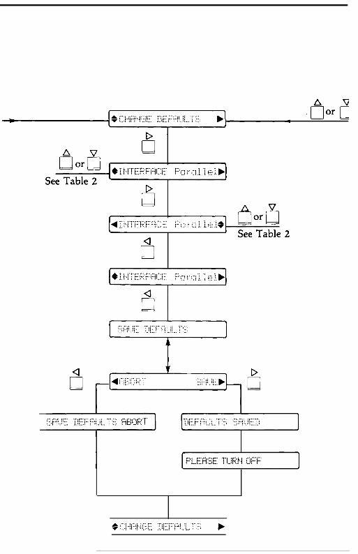
- I
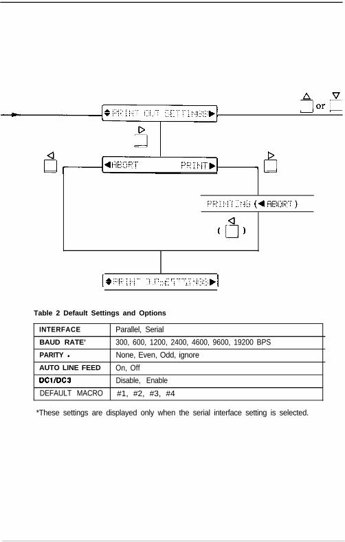
[ * ;:::F;, ;, yj “” :/; /‘j: ,..::..: ::::t::. i i ,j/ .::,,,:._:
... ?--T-r .r &.;;::::::,I
Table 2 Default Settings and Options
INTERFACE Parallel, Serial
BAUD RATE’ 300, 600, 1200, 2400, 4600, 9600, 19200 BPS
PARITY l None, Even, Odd, ignore
AUTO LINE FEED On, Off
DCIIDCB Disable, Enable
DEFAULT MACRO #1, #2, #3, #4
*These settings are displayed only when the serial interface setting is selected.
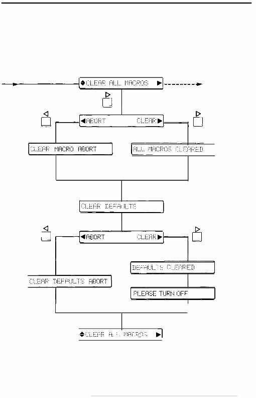
I* /./ y;-;i:-y /,& ; . . . . . .. ,:.... /- .,I. .::...v :... i.. c:..i 1;‘. : :: / ;:;p/! ,g;;; j,......: ,I

Commands Arranged by TopicThis section lists all the LQ-2550 commands. The numbers in the columns on theright are the page numbers in Chapter 8 where a complete description of thecommand can be found.
Printer Operation/Data Control1 Code 1 Dee 1 Hex 1 F u n c t i o n I Pace1
ESC @ 64 40 Initialize Printer 8-8
DC1 17 11 Select Printer 8-8
1 DC3 I 19 I 13 I Deselect Printer I 8-9 II DEL I 127 I 7 F I DeleteCharacter I 8-9 I
ESC <
ESC EM
ESC U
60 3C Select Unidirectional Mode (one line) 8-9
25 19 Cut Sheet Feeder Control 8-10
85 55 Turn Unidirectional Mode On/Off 8-10
1 ESC = 1 61 I 30 1 Set MSB to o 1 8-11 I
ESC > 62 3E Set MSB to 1 8-11
ESC # 35 23 Cancel MSB Control 8-l 1
1 BEL I 7 I 07 I Beeper I 8-12 I
1 CR I 13 I OD I Carriaoe Return I 8-12 ICAN 24 18 Cancel Line 8-12
Vertical Motion1 FF 1 12 1 OC 1 FormFeed 1 8-13 (
~!Cancel Skip Over Perforation
Set Vertical Tabs
ESC b 1 98 1 62 1 Set Vertical Tabs in Channels 1 8-17
ESC I 1 47 1 2F 1 Set Vertical Tab Channel 1 8-18

wizontal MotionSC I 108 6C Set Left Margin 8-18
sccl 81 51 Set Rrght Margin 8-18
S 8 08 Backspace 8-19
set 36 24 Set Absolute Print Posrtron 8-19
SC 1 92 5C Set Relative Pnnt Position 8-20
T 9 09 Tab Horizontally 8-20
SC D 68 44 Set Honzontal Tabs 8-21
erall Printing StvlelPrint Sizeode
sex
SC k
SC !
Dee Hex Function Page
120 78 Select Letter Quality or Draft 8-21
107 6B Select Typestyle Family 8-22
33 21 Master Select 8-22
SC P 1 80 1 50 1 Select 10 CPI 1 8-23 1
SC M 77 4D Select 12 cpi 8-23
32 g 103 67 Select 15 CPI 8-23
3.2 p 112 70 1 Turn Proportronal Mode On/Off 1 8-24
(ESC SI) I 15 I OF I Select Condensed Mode 1 8-24 I
c2 18 12 Cancel Condensed Mode 8-25
3 (ESC SO) 14 O E Select Double-Wade Mode (one line) 8-25
jcw 87 57 Turn Double-Wide Mode On/Off 8-25
54 20 14 Cancel Double-Wade Mode (one line) 8-26
32 w 119 77 Turn Double-Hugh Mode On/Off 8-26
nt Enhancement/Word ProcessirigX r 114 72 Select Printing Color
iC E 69 45 Select Emphasized Mode
8-27
8-27
;C F / 70 I 46 1 Cancel Emphasized Mode 1 8-27 1
iC G I 71 I 47 I Select Double-Strike Mode 1 8-28 1
iC H 72 48 Cancel Double-Strike Mode 8-28
ic so 83 53 Select Superscript Mode 8-28
ic Sl 83 53 Select Subscript Mode 8-28
iC T 84 54 Cancel Superscript/Subscript 8-29
ic - 45 20 Turn Underlining On/Off 8-29
C( - 40 28 Select Score 8-29
ic q I 113 I 71 I Select Character Style 1 8-29 1
iC a 97 61 Select Justification 8-30
iC SP(space) 32 20 Set Intercharacter Space 8-30

Character SetsESC t 116 74 Select Character Table 8-31
ESC 4 52 34 Select Italic Mode 8-31
ESC 5 53 35 Cancel Italic Mode 8-32
ESC R 82 52 Select an International Character Set 8-32
User-Defined Characters/Graphics
ESC ? 1 63 1 3F Reassign Graphics Mode ( 8-36
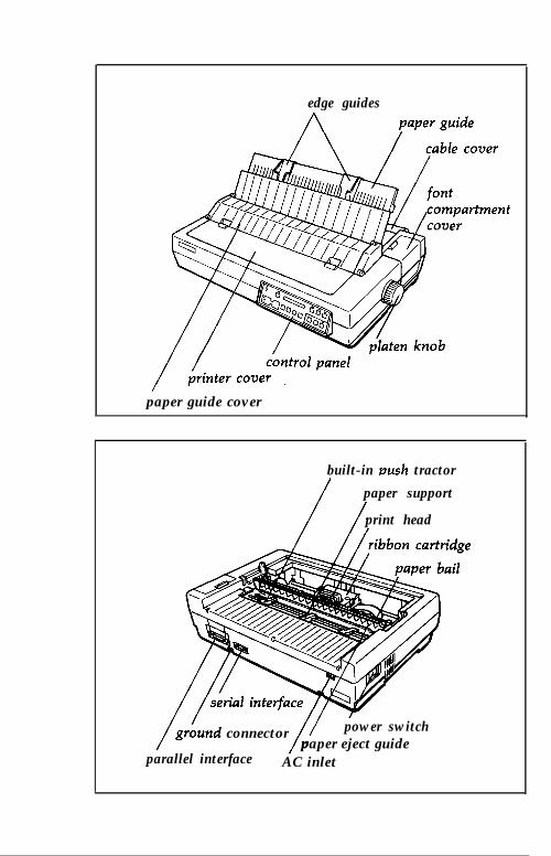
edge guides
paper guide cover
built-in push tractor
/
paper support
/print head/
/gr:und connector
// power switch
parallel interfacepaper eject guide
AC inlet

l-ltlUc

EPSON AMERICA, INC. 2780 Lomita Boulevard, Torrance, California 90505