Epson Stylus Color 400 Service Manual.pdf
201
-
Upload
francisco-lopez -
Category
Documents
-
view
58 -
download
8
Transcript of Epson Stylus Color 400 Service Manual.pdf

EPSON
COLOR INK-JET PRINTER
EPSON Stylus Color 400
SERVICE MANUAL
SEIKO EPSON CORPORATION
4007366

NOTICE
� All rights reserved. Reproduction of any part of this manual in any form whatsoever
without SEIKO EPSON’s express written permission is forbidden.
� The contents of this manual are subjects to change without notice.
� All efforts have been made to ensure the accuracy of the contents of this manual.
However, should any errors be detected, SEIKO EPSON would greatly appreciate
being informed of them.
� The above notwithstanding SEIKO EPSON can assume no responsibility for any errors
in this manual or the consequences thereof.
EPSON is a registered trademark of SEIKO EPSON CORPORATION.
General Notice:
Other product names used herein are for identification purposes only and may be
trademarks or registered trademarks of their respective companies.
Copyright 1997 by SEIKO EPSON CORPORATION
Nagano, Japan

PRECAUTIONSPrecautionary notations throughout the text are categorized relative to 1) personal injury and 2)
damage to equipment.
WARNING Signals a precaution which, if ignored, could result in serious or fatal personal injury.
Great caution should be exercised in performing procedures preceded by
WARNING Headings.
CAUTION Signals a precaution which, if ignored, could result in damage to equipment.
The precautionary measures itemized below should always be observed when performing
repair/maintenance procedures.
WARNING1. ALWAYS DISCONNECT THE PRODUCT FROM BOTH THE POWER SOURCE AND
PERIPHERAL DEVICES PERFORMING ANY MAINTENANCE OR REPAIR PROCEDURES.
2. NO WORK SHOULD BE PERFORMED ON THE UNIT BY PERSONS UNFAMILIAR WITH
BASIC SAFETY MEASURES AS DICTATED FOR ALL ELECTRONICS TECHNICIANS IN
THEIR LINE OF WORK.
3. WHEN PERFORMING TESTING AS DICTATED WITHIN THIS MANUAL. DO NOT
CONNECT THE UNIT TO A POWER SOURCE UNTIL INSTRUCTED TO DO SO. WHEN THE
POWER SUPPLY CABLE MUST BE CONNECTED, USE EXTREME CAUTION IN WORKING
ON POWER SUPPLY AND OTHER ELECTRONIC COMPONENTS.
CAUTION1. REPAIRS ON EPSON PRODUCT SHOULD BE PERFORMED ONLY BY EPSON CERTIFIED
REPAIR TECHNICIAN.
2. MAKE CERTAIN THAT THE SOURCE VOLTAGE IS THE SAME AS THE RATED VOLTAGE,
LISTED ON THE SERIAL NUMBER/RATING PLATE. IF THE EPSON PRODUCT HAS A
PRIMARY AC RATING DIFFERENT FROM AVAILABLE POWER SOURCE, DO NOT
CONNECT IT TO THE POWER SOURCE.
3. ALWAYS VERIFY THAT THE EPSON PRODUCT HAS BEEN DISCONNECTED FROM THE
POWER SOURCE BEFORE REMOVING OR REPLACING PRINTED CIRCUIT BOARDS
AND/OR INDIVIDUAL CHIPS.
4. IN ORDER TO PROTECT SENSITIVE MICROPROCESSORS AND CIRCUITRY, USE
STATIC DISCHARGE EQUIPMENT, SUCH AS ANTI-STATIC WRIST STRAPS, WHEN
ACCESSING INTERNAL COMPONENTS.
5. REPLACE MALFUNCTIONING COMPONENTS ONLY WITH THOSE COMPONENTS BY
THE MANUFACTURE; INTRODUCTION OF SECOND-SOURCE ICs OR OTHER
NONAPPROVED COMPONENTS MAY DAMAGE THE PRODUCT AND VOID ANY
APPLICABLE EPSON WARRANTY.

PREFACE
This manual describes functions, theory of electrical and mechanical operations, maintenance, and
repair of EPSON Stylus Color 400.
The instructions and procedures included herein are intended for the experience repair technician,
and attention should be given to die precautions on the preceding page. The Chapters are
organized as follows:
CHAPTER 1. GENERAL DESCRIPTIONProvides a general product overview, lists specifications, and illustrates the main components of the
printer.
CHAPTER 2. OPERATING PRINCIPLESDescribes the theory of printer operation.
CHAPTER 3. DISASSEMBLY AND ASSEMBLYIncludes a step-by-step guide for product disassembly and assembly.
CHAPTER 4. ADJUSTMENTIncludes a step-by-step guide for adjustment.
CHAPTER 5. TROUBLESHOOTINGProvides EPSON-approved techniques for troubleshooting.
CHAPTER 6. MAINTENANCEDescribes preventive maintenance techniques and lists lubricants and adhesives required to
service the equipment.
APPENDIXDescribes connector pin assignments, circuit diagrams, circuit board component layout and
exploded diagram.
The contents of this manual are subject to change without notice.

REVISION SHEET
Revision Issued Data Contents
Rev. A February18. 1997 First issue

TABLE OF CONTENTS
CHAPTER 1. GENERAL DESCRIPTIONCHAPTER 2. OPERATING PRINCIPLESCHAPTER 3. DISASSEMBLY AND ASSEMBLYCHAPTER 4. ADJUSTMENTCHAPTER 5. TROUBLESHOOTINGCHAPTER 6. MAINTENANCEAPPENDIX

Chapter 1Product Descriptions
1.1 Features.................................................................................................................1- 1
1.2 Specifications .......................................................................................................1-2 1.2.1 Printing Specification................................................................................................... .......... 1-2
1.2.2 Paper Specification ...................................................................................................... .......... 1-4 1.2.2.1 Cut Sheet................................................................................................................... 1-4 1.2.2.2 Transparency, Glossy Paper ..................................................................................... 1-4 1.2.2.3 Envelope.................................................................................................................... 1-4 1.2.2.4 Index Card................................................................................................................. 1-4
1.2.3 Adjust Lever Settings (PG adjust lever) ............................................................................... 1-5
1.2.4 Printing Area ............................................................................................................ ............... 1-5
1.2.5 Environmental Condition.................................................................................................. ..... 1-8
1.2.6 Ink Cartridge Specifications ............................................................................................. ..... 1-9
1.2.7 Physical Specification................................................................................................... ....... 1-11
1.2.8 Input Data Buffer ........................................................................................................ .......... 1-11
1.2.9 Electric Specification ................................................................................................... ........ 1-12
1.2.10 Reliability............................................................................................................. ................ 1-12
1.2.11 Safety Approvals........................................................................................................ ......... 1-12
1.2.12 Acoustic Noise.......................................................................................................... .......... 1-13
1.2.13 CE Marking.............................................................................................................. ............ 1-13
1.2.14 Printer Language and Emulation ...................................................................................... 1-13
1.3 Interface...............................................................................................................1-1 5 1.3.1 Parallel Interface (Forward Channel) .................................................................................. 1-1 5
1.3.2 Parallel Interface (Reverse Channel) .................................................................................. 1-1 6
1.3.3 Prevention Hosts from Data Transfer time-out.................................................................. 1-18
1.4 Control Panel ......................................................................................................1-19 1.4.1 Indicators............................................................................................................... ................ 1-19
1.4.2 Panel Functions.......................................................................................................... .......... 1-20
1.4.3 Printer Condition and Panel Status .................................................................................... 1-2 2
1.5 Error Status.........................................................................................................1-23 1.5.1 Ink Out .................................................................................................................. ................. 1-23
1.5.2 Paper Out................................................................................................................ ............... 1-23
1.5.3 Paper Jam................................................................................................................ .............. 1-23
1.5.4 No Ink-Cartridge ......................................................................................................... .......... 1-24
1.5.5 Maintenance Request...................................................................................................... ..... 1-24
1.5.6 Fatal Errors............................................................................................................. ............... 1-24
1.6 Printer Initialization ............................................................................................1-25
1.7 Initialization Settings..........................................................................................1-25
1.8 Main Components...............................................................................................1-26 1.8.1 Printer Mechanism ........................................................................................................ ....... 1-26
1.8.2 C206 Main Control Board.................................................................................................. ... 1-26
1.8.3 C206 PSB/PSE Power Supply Board .................................................................................. 1-27
1.8.4 C206PNL(Panel) Board ..................................................................................................... ... 1-27

EPSON Stylus Color 400 Service Manual
Rev. A 1-1
1.1 FeaturesStylus Color 400 is designed for PC users at home and low price for that high performance.Also, this printer has the same high color print quality(720X720dpi) as Stylus ProXL. The major printerfeatures are;
� High color print quality� 720(H) x 720(V) dpi printing� 4 color printing (YMCBk)� Traditional and New Microwave� Black 64 nozzles, CMY 21 nozzles (Black=180dpi, CMY=90dpi)� During 360 dpi printing, 1 dot is fired by 2 shots and 1 dot is fired by 1 shot during 720 dpi
printing.� Built-in auto sheet feeder
� Holds 100 cut-sheets (55g/m2)� Holds 10 envelopes� Holds 10 transparency films� Holds 65 special papers
� High-speed print� 200cps� By using head drive frequency 14.4KHz, printing speed is twice faster
than Stylus Color.� Compact size
� Non-operating : 429mm(W) x 234mm(D) x 162mm(H)� Operating : 429mm(W) x 695mm(D) x 309mm(H)� Weight : 5.2Kg(without cartridge)
� Acoustic noise� Approximately 45 dB
� Bi-directional parallel I/F(IEEE-1284 level 1 device)� One unit combined black and CMY head� Windows exclusive
The following table shows consumable and option.
Item Code RemarkBlack Ink Cartridge S020093 Color: BlackColor Ink Cartridge S020089 Color: Cyan/Magenta/YellowEPSON 360 dpi Ink Jet Paper S041025 Size: A4(200 sheets)EPSON 360 dpi Ink Jet Paper S041059 Size: A4(100 sheets)EPSON 360 dpi Ink Jet Paper S041060 Size: Letter(100 sheets)Photo Quality Ink Jet Paper S041026 Size: A4(200 sheets)Photo Quality Ink Jet Paper S041061 Size: A4(100 sheets)Photo Quality Ink Jet Paper S041062 Size: LetterPhoto Quality Ink Jet Paper S041067 Size: LegalPhoto Quality Glossy Paper(New Release) S041126 Size: A4Photo Quality Glossy Paper(New Release) S041124 Size: LetterPhoto Quality Glossy Film S041071 Size: A4Photo Quality Glossy Film S041124 Size: LetterPhoto Quality Glossy Film S041107 Size: A6Ink Jet Transparencies S041063 Size: A4Ink Jet Transparencies S041064 Size: LetterPhoto Quality Ink Jet Card S041054 Size: A6Photo Quality Ink Jet Card S041121 Size: 5 x 8 inchesPhoto Quality Ink Jet Card S041122 Size: 10 x 8 inchesPhoto Quality Self Adhesive Sheet S041106 Size: A4
Table 1-1. Consumable

Chapter1 Product Description
Rev. A1-2
1.2 SpecificationsThis section describes each specification for Stylus Color 400; 1) Printing specification, 2) Paperspecification, 3) Adjust lever settings, 4) Printing area, 5) Environmental condition, 6) Ink Cartridgespecification, 7) Physical specification, 8) Electric specification, 9) Reliability.
1.2.1 Printing Specification� Print method
� On demand ink jet (MACH type. One unit combined with black and CMY head)
� Nozzle configuration� Black 64 nozzles (32x2 staggered), Color 21 nozzles x 3 (Cyan, Magenta, Yellow)
(Black = Staggering 2 lines, 180 dpi, CMY= one line for each color, 90 dpi)Note) During 360 dpi printing mode, one line is completed by 2-pass for black and by 4-pass for CMY.
� Print direction� Bi-direction with logic seeking
� Print speed and Printable columns, character pitch and print quality� 360 dpi printing mode= 200 cps (Head drive frequency 14.4KHz)� 720 dpi printing mode= 200 cps (Head drive frequency 14.4KHz)� About 80 columns� 10 pitch� High quality (No draft mode)
� Printable area, available dot CR speed at Raster graphics mode� Refer to table 1-2.
Horizontal resolution Printable area Available dot CR Speed180 dpi 8.26 inch 1488 20 IPS360 dpi 8.26 inch 2976 20 IPS720 dpi 8.26 inch 5952 20 IPS
� Nozzle configuration� Refer to figure 1-1.
Table 1-2.Raster Graphics Mode
(B2)
#1
#3
#5
C2
C3
C4
Y2
Y3
Y4
(C)(M)(Y)
90DPI 180DPI
#23#24
Y20
Y21
#60
#62
#64
#59
#61
#25#26
2.2578 mm7.9022 mm10.16 mm2.2578 mm
(B1)
#63
C1
C19
C20
C21
M 1
M 2
M 19
M 20
M 21
M 3
M 4
Y1
Y19
Figure1-1. Stylus Color 400 NozzleConfiguration
EPSON Stylus Color 400 Service Manual
Rev. A 1-3
� Feeding method� Friction feed with ASF
� Paper feed resolution� 0.035mm(1/720 inch)
� Line spacing� 1/6 inch or programmable at 1/360 inch
� Paper path� Cut-sheet ASF(Top entry)
� Feeding speed� 66.6ms (1/6 inch)� 153.7ms (9.03mm line spacing)� 76.2ms (continues 3.0 inch/sec)
� Ink supply� Exclusive ink cartridge(Black and CMY)
� Paper holding capacity of Hopper� Size : Index card ∼Legal� Thickness : Less than 8mm� Paper capacity : 100 Cut sheets
: 10 Envelopes: 65 Coated papers (360 dpi): 65 Coated papers (720 dpi): 30 Glossy papers: 10 Transparent sheets: 30 Index cards
Note) Those numbers above should be considered as reference. The actual paper accumulation should be considered first.
� Character tables : 2 international character sets(Not Opened)� PC437(US, Standard Europe)� PC850(Multilingual)
� Typeface� Bit map LQ font : EPSON Courier 10CPI
� Control code� ESC/P Raster� EPSON Remote command

Chapter1 Product Description
Rev. A1-4
1.2.2 Paper SpecificationThis section describes the printable area and types of paper that can be used in this printer.
1.2.2.1 Cut Sheet
[Size] : A4 [Width 210mm(8.3”) x Length 297mm(11.7”)]: Letter [Width 216mm(8.5”) x Length 279mm(11.0”)]: B5 [Width 182mm(7.2”) x Length 257mm(10.1”)]: Legal [Width 216mm(8.5”) x Length 356mm(14.0”)]: Statement [Width 139.7mm(5.5”) x Length 215.9mm(8.5”)]: Exclusive [Width 190.5mm(7.5”) x Length 254mm(10”)]
[Thickness] : 0.08mm(0.003”) - 0.11mm(0.004”)
[Weight] : 64g/m2(17Ib.) - 90g/m2(24Ib.)
[Quality] : Exclusive paper, Bond paper, PPC
1.2.2.2 Transparency, Glossy Paper
[Size] : A4[Width 210mm(8.3”) x Length 297mm(11.7”)]: Letter[Width 216mm(8.5”) x Length 279mm(11.0”)]
[Thickness] : 0.075mm(0.003”) - 0.085mm(0.0033”)
Note) Transparency printing is only available at normal temperature.
1.2.2.3 Envelope
[Size] : No.10 Width 241mm(9 1/2”) x Length 104.8mm(4 1/8”): DL Width 220mm(8.7”) x Length 110mm(4.3”): C6 Width 162mm(6.4”) x Length 114mm(4.5”)
[Thickness] : 0.16mm(0.006”) - 0.52mm(0.02”)
[Weight] : 45g/m2 (12Ib.) - 75g/m2 (20Ib.)
[Quality] : Bond paper, Plain paper, Air mail
Note 1) Envelope printing is only available at normal temperature.Note 2) Keep the longer side of the envelope horizontally at setting.
1.2.2.4 Index Card
[Size] : A6 Index card: Width 105mm(4.1”) x Length 148mm(5.8”): A5 Index card: Width 148mm(5.8”) x Length 210mm(8.3”): 5x8” Index card: Width 127mm(5.0” x Length 203mm(8.0”): 10x8” Index card: Width 127mm(5.0”) x Length 203mm(8.0”)
[Thickness] : Less than 0.23mm(0.0091”)
Note 1) No curled, wrinkled, scuffing or torn paper be used.Note 2) Set the lever to the proper position according to the paper type you print. (Refer to section
1.2.3 for details)Note 3) Printing should be performed at room temperature in spite of the paper types.

EPSON Stylus Color 400 Service Manual
Rev. A 1-5
1.2.3 Adjust Lever Settings (PG adjust lever)The adjust lever located on the right side(blue) under the printer cover needs to be set to the properposition according to the paper you print. (Refer to the table below). Also, if there is any dirt caused byfriction on the wavy or wrinkled paper, this can be prevented by changing the lever position to rearposition (marked with “+”) in spite of paper types.
Paper Lever position PG adjustment valueNormal paper,Coated paper
Front 0 mm (1.1mm between head and platen)
Envelopes Rear 0.9 mm (2.0mm between head and platen)
Table 1-3.Adjust Lever Settings
Front (Mark "0") Rear (Mark "+")
CR Guide Shaft
Bush
Level adjustment lever
Figure 1-2. Adjust Lever Settings

Chapter1 Product Description
Rev. A1-6
1.2.4 Printing Area
[Cut Sheet]Following tables show printable areas at Character mode and Raster Graphics mode.
Paper size PW(Paperwidth)(typ)
PL(PaperLength)
(typ.)
LM(Leftmargin)(min.)
RM(Rightmargin)(min.)
TM(Topmargin)(min.)
BM(Bottommargin)(min.)
A4 210mm(8.3”) 297mm(11.7”) 3mm(0.12”) 3mm(0.12”) 3mm(0.12”) 14mm(0.54”)Letter 216mm(8.5”) 279mm(11.0”) 3mm(0.12”) 9mm(0.35”) 3mm(0.12”) 14mm(0.54”)B5 182mm(7.2”) 257mm(10.1”) 3mm(0.12”) 3mm(0.12”) 3mm(0.12”) 14mm(0.54”)Legal 216mm(8.5”) 356mm(14.0”) 3mm(0.12”) 9mm(0.35”) 3mm(0.12”) 14mm(0.54”)Statement 139.7mm(5.5”) 215.9mm(8.5”) 3mm(0.12”) 3mm(0.12”) 3mm(0.12”) 14mm(0.54”)Executive 190.5mm(7.5”) 254mm(10”) 3mm(0.12”) 3mm(0.12”) 3mm(0.12”) 14mm(0.54”)
Paper size PW(Paperwidth)(typ)
PL(PaperLength)
(typ.)
LM(Leftmargin)(min.)
RM(Rightmargin)(min.)
TM(Topmargin)(min.)
BM(Bottommargin)(min.)
A4 210mm(8.3”) 297mm(11.7”) 3mm(0.12”) 3mm(0.12”) 3mm(0.12”) 14mm(0.54”)Letter 216mm(8.5”) 279mm(11.0”) 3mm(0.12”) 3mm(0.12”) 3mm(0.12”) 14mm(0.54”)B5 182mm(7.2”) 257mm(10.1”) 3mm(0.12”) 3mm(0.12”) 3mm(0.12”) 14mm(0.54”)Legal 216mm(8.5”) 356mm(14.0”) 3mm(0.12”) 3mm(0.12”) 3mm(0.12”) 14mm(0.54”)Statement 139.7mm(5.5”) 215.9mm(8.5”) 3mm(0.12”) 3mm(0.12”) 3mm(0.12”) 14mm(0.54”)Executive 190.5mm(7.5”) 254mm(10”) 3mm(0.12”) 3mm(0.12”) 3mm(0.12”) 14mm(0.54”)
Table 1-4. Character Table
Table 1-5. Raster Graphics Mode
PW
LM RM
TM
BM
PLPrintable Area
Figure 1-3. Printing Area for Cut Sheets
EPSON Stylus Color 400 Service Manual
Rev. A 1-7
[Envelope]The table and figure below show the printable area for envelopes.
Paper size LM(Left margin)(min.)
RM(Right margin)(min.)
TM(Top margin)(min.)
BM(Bottommargin)(min.)
#10 3mm(0.12”) 28mm(1.10”) 3mm(0.12”) 14mm(0.55”)DL 3mm(0.12”) 7mm(0.28”) 3mm(0.12”) 14mm(0.55”)C6 3mm(0.12”) 3mm(0.12”) 3mm(0.12”) 14mm(0.55”)
Table 1-6. Printable Area for Envelope
LM RM
TM
BM
Printable area
Figure 1-4. Printing Area for Envelope

Chapter1 Product Description
Rev. A1-8
1.2.5 Environmental Condition
� Temperature� Operating :10 to 35 °C (Refer to the figure below for condition)� Non-operating : -20 to 60 °C(with shipment container)
Note) 1 month at 40 °C and 120 hours at 60 °C
� Humidity� Operating : 20% � 80% RH (without condensation. Refer to the figure below for
condition)� Non-operating : 5% � 85% RH (without condensation and with shipment container)
� Resistance to shock� Operating : 1G, within 1 ms X,Y,Z directions� Non-operating : 2G, within 2 ms X,Y,Z directions (with shipment container)
� Resistance to vibration� Operating : 0.15G, 10�55Hz X,Y,Z directions� Non-operating : 0.50G, 10�55Hz X,Y,Z directions (with shipment container)
Note 1) During non-operating, make sure that the head is capped.Note 2) During the transport, make sure that the head is capped and ink cartridge is
installed to the printer.Note 3) If the head is not capped at the power-off state, turn the power on with installed ink
cartridge and turn off the power after confirming that Power on operation is completed andthe head is capped.
Note 4) Ink will be frozen under -4°C environment, however it will be useable after placing itmore than 3 hours at 25°C.
Humidity(% RH)
°C(°F)
80%
55%
20%
10°C(50°F)
27°C(80°F)
35°C(95°F)
Guaranteed range
Figure 1-5. Temperature/Humidity of Range
EPSON Stylus Color 400 Service Manual
Rev. A 1-9
1.2.6 Ink Cartridge Specifications[Black Ink Cartridge]
Item SpecificationsType Exclusive cartridgeColor BlackPrint capacity 540 pages / A4 (ISO/IE10561 Letter Pattern at 360 dpi)Validity 2 years (sealed in package) / 6months(out of package)Environmentalconditions
� Temperature� Storage : -20°C�40°C(within a month at 40°C)� Packing storage : -30°C�40°C (within a month at 40°C)� Transit : -30°C�60°C (within 120 hours at 60°C and within a
month at 40°C)� Humidity
� 5%�85%(without condensation)� Resistance to vibration
� Sealed in package : 5�55Hz� Acceleration : 29.4m/s less than <3G>� Direction : X, Y, Z direction� Time : 1 hour
� Drop� Sealed in package :
� Dropping height : Less than 0.08m� Direction : Drop the printer facing the bottom, sides and one
edge down.� Out of package:
� Dropping height : Less than 1.50m� Frequency : Once
Dimension 19.8mm(W) x 52.7(D) x 38.5mm(H)Weight � Total ink cartridge : 54g
� Total ink : 16.4 ± 0.5g (Quantity in the ink cartridge)� Consumable ink : More than 12.1g(Useable ink quantity until ink ends)
Note 1) Ink cartridge can not re-fill, only ink cartridge is prepared for article of consumption.Note 2) Do not use the ink cartridge which is passed away the ink life.Note 3) Ink will be frozen under -4°C environment, however it will be usual after placing it more than
3 hours at room temperature.
Table 1-7.Black Cartridge Specification
18.3
38.5
51.2
19.8
52.7
Figure 1-6. Ink Cartridge (Black)
Chapter1 Product Description
Rev. A1-10
[Color Ink Cartridge]
Item SpecificationsType Exclusive cartridgeColor Magenta, Cyan, YellowPrint capacity 320 pages / A4 (360 dpi, 5% duty each color)Validity 2 years (sealed in package) / 6months(out of package)Environmentalconditions
� Temperature� Storage : -20°C�40°C (within a month at 40°C)� Packing storage : -30°C�40°C (within a month at 40°C)� Transit : -30°C�60°C (within 120 hours at 60°C and within a month
at 40°C)� Humidity
� 5%�85%(without condensation)� Resistance to vibration
� Sealed in package : 5�55Hz� Acceleration : 29.4m/s less than <3G>� Direction : X, Y, Z direction� Time : 1 hour
� Drop� Sealed in package :
� Dropping height : Less than 0.08m� Direction : Drop the printer facing the bottom, sides and one
edge down.� Out of package:
� Dropping height : Less than 1.50m� Frequency : Once
Dimension 42.9mm(W) x 52.7(D) x 38.5mm(H)Weight � Total ink cartridge : 68g
� Total ink : 13.3 � 0.5g (Quantity in the ink cartridge)� Consumable ink : More than 10.1g/each color(Useable ink quantity until
ink ends)
Note 1) Ink cartridge can not re-fill, only ink cartridge is prepared for article of consumption.Note 2) Do not use the ink cartridge which is passed away the ink life.Note 3) Ink will be frozen under -4°C environment, however it will be usual after placing it more than
3 hours at room temperature.
Table 1-8. Color Ink Cartridge Specification
41.4
38.5
51.2
43.2
42.9
52.7
Figure 1-7. Ink Cartridge (Color)

EPSON Stylus Color 400 Service Manual
Rev. A 1-11
1.2.7 Physical Specification
[Dimension] : 429mm(W) x 234mm(D) x 162mm(H): 429mm(W) x 695mm(D) x 309mm(H) with extended stacker and paper support.
[Weight] : 5.2Kg
1.2.8 Input Data Buffer10 K byte
Chapter1 Product Description
Rev. A1-12
1.2.9 Electric Specification
[120V version]
[Rated voltage] : AC120V
[Input voltage range] : AC103.5∼132V
[Rated frequency range] : 50∼60Hz
[Input frequency range] : 49.5∼60.5Hz
[Rated current] : 0.4A(Max. 0.5A)
[Power consumption] : Approx.15W(ISO/IEC 10561 Letter pattern): Energy Star compliant
[Insulation Resistance] : 10M ohms min.(between AC line and chassis, DC500V)
[Dielectric strength] : AC1000 V rms. 1 minute or AC1200 Vrms. 1 second (between AC line and chassis)
[220∼240V version]
[Rated voltage] : AC220V∼240V
[Input voltage range] : AC198∼264V
[Rated frequency range] : 50∼60Hz
[Input frequency range] : 49.5∼60.5Hz
[Rated current] : 0.2 A(Max. 0.3A)
[Power consumption] : Approx.15W(ISO/IEC 10561 Letter pattern): Energy Star compliant
[Insulation Resistance] : 10M ohms min.(between AC line and chassis, DC500V)
[Dielectric strength] : AC1500 V rms. 1 minute (between AC line and chassis)
1.2.10 Reliability
[Total print volume] : 10,000 pages(A4, letter)[Print head life] : 2000 million dots/nozzle
1.2.11 Safety Approvals
[120V version]Safety standard : UL1950 with D3
: CSA22.2 No.950 with D3EMI : FCC part 15 subpart B class B
: CSA C108.8 class B
[220∼240V]Safety standard : EN 60950(VDE,NEMKO)EMI : EN55022(CISPR Pub.22) class B
: AS/NZS 3548 class B

EPSON Stylus Color 400 Service Manual
Rev. A 1-13
1.2.12 Acoustic Noise
[Level] : Approx.45 dB(A) (According to ISO 7779)
1.2.13 CE Marking
[220-240V version]Low voltage Directive 73/23/EEC :EN60950EMC Directive 89/336/EEC :EN55022 Class B
EN61000-3-2 EN61000-3-3 EN50082-1 IEC801-2 IEC801-3 IEC801-4
1.2.14 Printer Language and Emulation
[Printer Language] : ESC/P Raster: EPSON Remote
[ESC/P control codes]< Character mode >� General Operation
� Initialize Printer : ESC@
� Paper feeding� Form Feed : FF� Line Feed : LF� Carriage Return : CR
<Graphic mode>� General operation
� Initialize Printer : ESC@� Unidirectional Printing : ESC U� CSF Mode Control : ESC EM
� Paper feeding:� Form Feed : FF� Line Feed : LF� Line Spacing : ESC+� Carriage Return : CR
� Page format� Page Length : ESC(C� Top/Bottom Margin : ESC(c
� Print position motion� Horizontal Print Position : ESC$,ESC\� Vertical Print Position : ESC (V,ESC (v
� Spacing� Define Unit : ESC(U
� Graphics� Graphics Mode : ESC(G� Raster Graphics : ESC.� Micro weave control : ESC(i
� Printing mode� Printing mode : ESC(K

Chapter1 Product Description
Rev. A1-14
� Color� Printing color : ESC r, ESC(r
� EEPROM control� EEPROM control : ESC

EPSON Stylus Color 400 Service Manual
Rev. A 1-15
1.3 InterfaceThis printer provides parallel interface as standard.
1.3.1 Parallel Interface (Forward Channel)
[Transmission mode] : 8 bit parallel, IEEE-1284 compatibility mode[Synchronization] : By /STOPBE pulse[Handshaking] : BY BUSY and /ACKLG signal[Signal level] : TTL compatible level[Adaptable connector] : 57-30360(amphenol) or equivalent
BUSY signal is set high before setting either/ERROR low or PE high and held high until all thesesignals return to their inactive state.
BUSY signal is at high level in the following cases.� During data entry (see Data transmission timing)� When input data buffer is full� During -INIT signal is at low level or during hardware initialization� During printer error (See /ERROR signal)
/ERROR signal is at low level when the printer is in one of the following states.� Printer hardware error (fatal error)� Paper-out error� Paper-jam error� Ink-out error
PE signal is at high level during paper-out error.
Table 1-9 shows the signal and connector pin assignments for parallel interface(forward channel*1).In case of these signals, twist pair line is used and returning side is connected to signal GND.(*1): Forward channel is the mode when the ordinary data such as an order to print is sent from the PC to the printer.
Pin No. Signal Name Return GND pin In/Out Functional Description1 /STROBE 19 In The strobe pulse. Read-in of data is performed
at the falling edge of this pulse.2-9 DATA0-7 20-27 In The DATA0 through DATA7 signals represent
data bits 0 to 7, respectively. Each signal is athigh level when data is logical 1 and low levelwhen data is logical 0.
10 /ACKNLG 28 Out This signal is a negative pulse indicating thatthe printer can again accept data.
11 BUSY 29 Out A high signal indicates that the printer cannotreceive data.
12 PE 28 Out A high signal indicates paper-out error.13 SLCT 28 Out Always at high level when the printer is
powered on.14 /AFXT 30 In Not used.31 /INIT 30 In The falling edge of a negative pulse or a low
signal on this line causes the printer toinitialize. Minimum 50 us pulse is necessary.
32 /ERROR 29 Out A low signal indicates printer error condition.36 /SLIN 30 In Not used.18 Logic H - Out Pulled up to +5V via 3.9K ohm resistor.35 +5V - Out Pulled up to +5V via 3.3K ohm resistor.17 Chassis GND - - Chassis GND.
16,33,19-30 GND - - Signal GND.15,34 NC - - Not connected.
Note) In/Out refers to the direction of signal flow from the printer’s point of view.
Table 1-9. Signal and Connector Pin Assignment for Parallel Interface

Chapter1 Product Description
Rev. A1-16
1.3.2 Parallel Interface (Reverse Channel)[Transmission mode] : IEEE-1284 nibble mode[Synchronization] : Refer to the IEEE-1284 specification[Handshaking] : Refer to the IEEE-1284 specification[Data trans. timing] : Refer to the IEEE-1284 specification[Signal level] : IEEE-1284 level 1 device
: TTL compatible level[Adaptable connector] : 57-30360(amphenol) or equivalent[Extensibility request] : The printer responds affirmatively when the extensibility
request values are 00H or 04H, that mean, 00H :Request Nibble Mode Reverse Channel Transfer. 04H :Request device ID; Return Data using Nibble Mode Rev
Channel Transfer.Note) The printer sends following device ID string when it is requested.
<00H> <3CH> ContentsMFG EPSON Production MakerCMD ESCPL2,BDC Command systemMDL Stylus[SP]Color[SP] 400 Model nameCLS PRINTER Class
Note) [00H] denotes a hexadecimal value of zero. MDL value depends on the EEPROM setting.Note) MDL value depends on the EEPROM setting. Model name can be changed by changing a
certain address in the EEPROM.The table below shows pin assignment for reverse channel(*3). In these case of signals, twist pair lineis used and returning side is connected to Signal GND.(*3): Reverse channel is the mode that any data istransferred from the printer to the PC.
Table 1-11. Pin Assignment for Reverse ChannelPin No. Signal Name Return
GND pinIn/Out Functional description
1 HostClk 19 In Host clock signal.2-9 Data0-7 20-27 In The DATA0 through DATA7 signals
represent data bits 0 to7, respectively.Each signal is at high level when datais logical 1 and low level when data islogical 0. These signals are used totransfer the 1284 extensibility requestvalues to the printer.
10 PrtClk 28 Out Printer clock signal.11 PtrBusy, Data Bit-3,7 29 Out Printer busy signal and reverse
channel transfer data bit 3 or 7.12 AckDataReq, DataBit-2,6 28 Out Acknowledge data request signal and
reverse channel transfer data bit 2 or6.
13 Xflag, DataBit-1,5 28 Out X-flag signal and reverse channeltransfer data bit 1 or 5.
14 HostBusy 30 In Host busy signal.31 /INIT 30 In Not used.32 /DataAvail, DataBit-0,4 29 Out Data available signal and reverse
channel transfer data bit 0 or 4.36 1284-Active 30 In 1284 active signal.18 Logic-H - Out Pulled up to +5V via 3.9K ohm resister.35 +5V - Out Pulled up to +5V via 3.3K ohm resister.17 Chassis GND - - Chassis GND.
16,33,19-30 GND - - Signal GND.15,34 NC - - Not connected.
Note) In/Out refers to the direction of signal flow from the printer’s point of view.
Table 1-10. Device ID Description
EPSON Stylus Color 400 Service Manual
Rev. A 1-17
Following lists “Notes” when using Parallel Interface.
Note1) “Return GND pin” in the table means twist pair return and is used for all control signalsexcept for Logic H,+5V, Chassis, GND and NC. In this twist pair return, returning sideis connected to GND (16,33, 19-30 pin) for twist pair return. Also, these cables are shieldedwires and it is effective to connect to each chassis GND in the PC and printer for electrostaticnoise.
Note2) Conditions for Interface are based on TTL level. Rise and fall time should be within 0.2µs.
Note3) Refer to the figure 1-8 for transmission timing of each signals.
Note4) Do not perform data transmission ignoring /ACK or BUSY signal. (Perform the data transmissionafter confirming that /ACK and BUSY signals are Low.)
Note5) It is possible to perform the printing test including interface circuit without using equipmentfrom outside when 8-bit data signal(20-27 pin) is set to appropriate word code and connectthem forcefully to /ACK and /STRB.
[Data Transmission Timing for Forward Channel]
Parameter Minimum Maximumtsetup 500ns ---thold 500ns ---tstb 500ns ---
tready 0 ---tbusy --- 500nstt-out* --- 120nstt-in** --- 200nstreply 0 ---tack 500ns 10us
tnbusy 0 ---tnext 0 ---
* Rise and fall time of every output signals.** Rise and fall time of every input signals.
Typical time of tack is shown below.
Parallel I/F mode Typical time of tackHigh speed 2us
Normal speed 4us
Byte Data n Byte Data n+1
Thold
Tsetup
Tstrb
Tnext
Tready Tbusy
Treply Tack Tnbusy
Data
/STROBE
BUSY
/ACKNLG
Figure 1-8. Parallel Interface Timing Chart(Forward Channel)
Table 1-12. Maximum and Minimum Timing for Data Transmission
Table 1-13. Typical Time of Tack
Chapter1 Product Description
Rev. A1-18
[Signal level: TTL compatible (IEEE-1284 level 1 device)]
Parameter Minimum Maximum ConditionVOH* --- 5.5VVOL* -0.5V ---IOH* --- 0.32mA VOH = 2.4VIOL --- 12mA VOL = 0.4VCO --- 50pFVIH --- 2.0VVIL 0.8V ---IIH --- 0.32mA VIH = 2.0VIIL --- 12mA VIL = 0.8VCI --- 50pF
*A low logic level on the Logic H signal is 2.0V or less when the printer is powered off and thissignal is equal or exceeding 3.0V when the printer is powered on. The receiver shall provide animpedance equivalent to 7.5K ohm to ground.
[Data Transmission Timing for Reverse Channel]
The figure below shows timing chart of Parallel Interface Reverse channel.
1.3.3 Prevention Hosts from Data Transfer time-out
Generally, hosts abandon data transfer to peripherals when a peripheral is in the busy statefor dozens of seconds continuously. To prevent hosts this kind of time-out, the printer receivesdata very slowly, several bytes per minute, even if the printer is in busy state. This showdownis started when the rest of the input buffer becomes several hundreds of bytes. Finally, the printer isin the busy state continuously when the input buffer is full.
Table 1-14. Signal Level
Virtual Busy Status Virtual Busy Status
Figure 1-9. Parallel Interface Timing Chart(Reverse Channel)

EPSON Stylus Color 400 Service Manual
Rev. A 1-19
1.4 Control PanelSince Stylus Color 400 does not require many buttons since printer driver can start various settings andmotions. Therefore, there are only 2 non-lock type push switches, 1 lock type push switch and 4 LEDs.Following figure shows control panel of Stylus Color 400.
1.4.1 Indicators
(1) PowerLights when the operate switch is “ON”, and AC power is supplied.
(2) Paper outLights during the paper-out condition, and blinks during the paper-jam condition.
(3) Ink Out (Black)Lights during no Black ink condition, and blinks during the Black ink low condition.
(4) Ink Out (Color) Lights during no Color ink condition, and blinks during the Color ink low condition.
Paper Out LED
Ink Out(Bk) LED
Ink Out(CMY) LED
Cleaning Switch(Ink maintenance)
Load/Eject Switch Power on Switch
Power LED
Figure 1-10. Control Panel

Chapter1 Product Description
Rev. A1-20
1.4.2 Panel Functions
< Panel Functions >
Switch FunctionLoad/Eject
(Pushing within 2 seconds*)� Loads or Eject the paper.� When carriage is on the Ink Cartridge change position, return carriage from Ink Cartridge change position.
Load/Eject(Pushing for 2 seconds*)
� Starts the Ink Cartridge change sequence.** Moves the carriage to cartridge change position.
Cleaning(Pushing for 2 seconds*)
� Stars the Cleaning of head.� In the condition of “Ink Low” or “Ink Out” or “No Ink Cartridge” starts the Ink Cartridge change sequence.**
Cleaning(Pushing within 2 seconds*)
� When carriage is on the Ink Cartridge change position, return carriage from Ink Cartridge change position.
Note) * 3 seconds is required at the User’s manual. ** This function is not available in printing status. <Panel Functions with Power ON >
Switch FunctionLoad/Eject � Stars status printings.**Cleaning � Changes a Code Page.
Load/Eject+
Cleaning
� Enters the particular settings mode. (Factory use only.) To enter the particular settings mode, it is necessary to push the cleaning switch while Paper Out LED is blinking.(It blinks about 3 seconds)
Note) ** status printings prints firmware version, ink counter, selected code page and nozzle check patterns.
<Maintenance Error Reset >
Switch FunctionCleaning � Initialize EEPROM and reset timer IC.
Note) The next page explains the detail procedure of the EEPROM reset.
Table 1-15. Panel Function
Table 1-16. Panel Function with Power On
Table 1-17. Particular Setting Mode

EPSON Stylus Color 400 Service Manual
Rev. A 1-21
[Maintenance Error Reset Procedure]You can reset the maintenance error by pressing the cleaning switch after you enter the particular settingmode(Refer to table 1-15.) There are no function which can be reset the all address in EEPROM on theStylus Color 400. Followings are detail procedure of maintenance error reset operation.
� Stylus Color 400 does not have “All Clear function” for EEPROM like other printers. Therefore, it is not necessary to replace the new ink cartridge after you perform this reset operation.
� Be sure to replace a waste ink pad in the printer enclosure with a new one after you perform this maintenance error reset operation.
[Step 1] By pushing Load/Eject and Cleaning switches at the same time, turn on the switch.(By operating this performance, the LED for paper out starts blinking.<3-seconds only>)
[Step 2] Push the cleaning switch while the LED for Paper Out is blinking (3 seconds).
Note) If the printer accepts this function correctly, it returns to the standby mode after theMaintenance LEDs(both Black and CMY) blink for 1 second. Following shows the lists that willbe cleared by this performance.
1. Maintenance Error Reset2. Time IC Reset3. I/F selection (returns to AUTO)
*** The value of ink counter, Bi-D adjustment, VH voltage are not cleared. ***
WARNING

Chapter1 Product Description
Rev. A1-22
1.4.3 Printer Condition and Panel Status
The table below shows printer condition and panel status. Since this table shows various errorstatus and also present printer status, you can judge appropriate repair ways from this table.
IndicatorsPrinter status Power Ink Out
(Black)Ink Out(Color)
Paper Out Priority
Power on condition On --- --- --- 9Ink sequence Blink --- --- --- 6Ink Cartridge changemode
Blink --- --- --- 5
Data processing Blink --- --- --- 8Paper Out --- --- --- On 4Paper jam condition --- Off Off Blink 3No Ink cartridge or Inkend(black)
--- On --- --- 7
Ink level low(black) --- Blink --- --- 7No Ink cartridge or Inkend(color)
--- --- On --- 7
Ink level low(color) --- --- Blink --- 7Enter EEPROM andTimer IC reset
--- On(1 second only)
On(1 second only)
On(1 second only)
--
Maintenance request Blink Blink Blink Blink 2Fatal error Blink On On Blink 1
Note1*): Refer to section 1.3.3 for error status.Note2*): It does not mean that all address would be cleared.Note3*): -- means no changes.
Table 1-18. Printer Condition and Panel Status

EPSON Stylus Color 400 Service Manual
Rev. A 1-23
1.5 Error StatusWhen following status occur, the printer goes to the error status and stops taking data, settingthe /ERROR signal in the interface as “Low”, and Busy signal as “High”. At this time, the printergoes to non printable status. Refer to section 1.4.3 for more details of LED Panel indicators duringthe various error status.
1.5.1 Ink Out
When the printer runs out the most part of the ink of any one color, it warns ink-low and keeps printing.When the printer runs out the whole ink of any one color, it stops printing and indicates ink-out error.User is requested to install a new ink-cartridge in this state. A ink-cartridge once taken out shouldnever be used again. Re-installation of the cartridge not filled fully upsets the ink level detection andmay cause a serious problem in the print head as a result.
WARNING
� Never use the ink cartridge once taken out.
Following explains above warning sign.
[Step 1] After the cartridge is once taken out, bubbles come in from the ink supply hole located atthe top of cartridge and are absorbed into the head during printing performance.Therefore, the head will be unable to discharge the ink properly. Also, inevitableentering of bubbles when installing a new ink cartridge can be absorbed to ink itself sincethe ink itself in the cartridge is deaerated during the production process.However, this absorbing ability can last only about one hour after the cartridge is installed.
[Step 2] Even after the bubble absorbing ability described above stops, there is no worry aboutentering bubbles as long as the ink cartridge is being installed to the printer.However, if the ink cartridge which does not have absorbing ability any more is onceremoved from the printer, new coming bubbles into the cartridge will never disappearnaturally. These bubbles may cause not only printing malfunction but also thickening ink.This thickened ink goes into the head and clogs ink path in the head or nozzle and maycause serious head damage.
[Step 3] As standard specification for Stylus Color 400, ink consumption counter is reset whenthe ink cartridge is removed. If an ink cartridge is removed and re-installed unnecessarilythe value on the ink consumption monitor which the user can check will be wrong andprinter may keep printing even though the ink cartridge is installed empty.This may cause head damage.
1.5.2 Paper Out
When printer fails to load a sheet after power on operation including timer-cleaning is doneand Load/Eject button on the FF command or operation panel is pressed, it goes paper out error.
1.5.3 Paper Jam
When printer fails to eject a sheet even after feeding motion is completed or Load/Eject button onthe FF command or operation panel is pressed, it goes paper jam error.

Chapter1 Product Description
Rev. A1-24
1.5.4 No Ink-Cartridge
Following reasons can be the causes when printer goes this error mode.
1) When the printer is turned on for the first time. (This is a normal error state and it returns to the normal state after installing an ink cartridge according to the ink cartridge exchange operation.)
2) Ink cartridge exchange operation is done correctly.After the position of carriage is moved by exchange operation, if the cleaning switch is pushed withoutinstalling ink cartridge or if the carriage returns to the home-position automatically without doing anyoperation, it is considered as handling mistake. However, it returns to normal state by performingink exchange operation again and installing cartridge correctly.
3) If “No ink-cartridge error” appears even after the ink cartridge is installed, the printer must besomething wrong and around the sensor area in the carriage need to be repaired.
4) If sometimes printer can print normally but also sometimes “No ink-cartridge error” appears, theprinter must be something wrong. (Same reason as 3) above)
1.5.5 Maintenance Request
When the total quantity of ink wasted through the cleanings and flushing reaches to the limit, printerindicates this error and stops. The absorber in the printer enclosure is needed to be replaced withnew one by a service person.The ink quantity that is absorbed by the absorber (waste ink pad) is monitored by the software counter as“total ink counter”. This counter is added by point system and absorber’s maximum ability is set atthe following reference value.
✳29500 X 0.0102 ml = Approximately 301 ml
� 1-point = 0.0102 ml (the value which is multiplied evaporating rate and 1-dot ink weight 0.02 ml)
� 29500 = Maximum point number (Maintenance error threshold)
However, considering dispersion of ink absorbing quantity and the number of using nozzles, ink totalvalue is calculated by the following formula.
✳301 X 1.1 ÷ 63% = 526 ml (but up to 532ml can be retained)
WARNING
When you perform self- test after completing repairs, it is possible to check the present value of totalink counter and ink discharge conditions from all nozzles by performing status printing in the built-infunction. Therefore, make sure that the printer has enough value of total ink counter (if the number isclose to 29500 or not). If there is not enough value, the service man is required to judge if it isnecessary to clear EEPROM after replacing the absorber (waste ink pad) or not. Refer to section 1.4.2if you need to perform EEPROM Clear.
1.5.6 Fatal ErrorsWhen printer detects fatal errors such as carriage control error or CG access error, it goes to thiserror mode. Refer to followings for each error.
1) Carriage control Error : Parallel adjustment malfunction, Home-position malfunction, Timing belt tension malfunction, shortage of lubricant on the carriage guide shaft, etc.
2) CG Access Error : Short circuit, etc.

EPSON Stylus Color 400 Service Manual
Rev. A 1-25
1.6 Printer InitializationStylus Color 400 has three kinds of initialization methods. Following explains each initialization.
[1.Power-on initialization] This printer is initialized when turning the printer power on, or printer recognized the cold-reset command (remote RS command). When printer is initialized, following action is performed.
(a) Initializes printer mechanism.(b) Clears input data buffer.(c) Clears print buffer.(d) Sets default values.
[2.Operator initialization] This printer is initialized when turning the printer power on again within 10 seconds from last power off, or printer recognize the /INIT signal (negative pulse) of parallel interface. When printer is initialized, following action is performed.
(a) Cap the printer head.(b) Eject a paper.(c) Clears input data buffer.(d) Clears print buffer.(e) Sets default values.
[3. Software initialization] The ESC@ command also initialize the printer. When printer is initialized, following action is performed.
(a) Clears print buffer.(b) Sets default values.
1.7 Initialization Settings
Stylus Color 400 initializes following settings when the initialization is performed. Also, if the user changesthe settings in the Panel setting, Default setting or Remote command setting, values or settings whichare possible to be stored are initialized as initialization settings.
� Page position : Page heading location as present paper location� Line spacing : 1/6 inch� Right margin position : 80 lines� Left margin position : first line� Character pitch : 10CPI� Printing mode : Text mode (Not Raster graphics mode)

Chapter1 Product Description
Rev. A1-26
1.8 Main Components
Stylus Color 400 has following major units. Also, it is one of the major characteristics that the bottom ofthe Printer mechanism plays the role as Lower case at the same time. Each units from 2) to 4) aresimply explained as following.
1) Upper case2) Printer Mechanism3) C206 Main control board4) C206 PSB/PSE(Power Supply Board)5) C206 PNL(Panel Board)
1.8.1 Printer MechanismUnlike EPSON’s previous ink jet printer mechanisms, one of the major characteristics of Stylus Color400 is that the printer has no Engage/Dis-Engage mechanism in order to change over pump mechanismand paper feeding mechanism. In stead, however, this change-over control is done by the distinctionbetween turning direction of PF/Pump motor and position of present carriage unit. Also, another majorcharacteristic is that print head is changed to be one unit combined with black and CMY.Nozzle configuration for black is 64 nozzles (each line has 90-dpi and between #1-#2 has 180dpi).On the other hand, CMY nozzle has 21 nozzles(90dpi) for each color. Following figure showsexterior of mechanism.
1.8.2 C206 Main Control BoardC206 main control board controls Stylus Color 400 and consists of following major electric elements.
1) CPU (TMP95C061F) 5) EEPROM (3strings Serial Type:1K-bit)2) Gate Array (E05B44BA) 6) LB1845 (Motor Driver)3) Program ROM (EEPROM or MASK ROM) 7) With Heat Sink transistor A1469, C37464) D-RAM (1CAS/2WE Type: 1M-bit) (MACH head type)
CN1(Parallel I/F Connector)
CN8(Head Control)
CN10(Pwer Supply)
CN6(CR Motor)CN7(PF Motor)
Common Driver Transistor(Q7,Q9 with Heat Sink)
ASIC E05B44(IC2)
CPU TMP95C061 (IC1)
Dinamic RAM(IC4)Reset for Logic (IC8)
Reset for Power (IC9)
1K-bit EEPROM(IC11)
Carriage Motor Driver(IC14)
PF Motor Driver(IC15)
Trapezoidal Wave form Driver(IC6)
Transceiver for Serial I/F(IC16)
CN3(Panel I/F)CN5(CRHP Sensor)CN4(PE Sensor)CN11(ASF phase Sensor)
Program ROM(EP-ROM or MASK ROM)
CN2(RS422 Serial I/F)
Battery for timer IC
Figure 1-11. Exterior of C206 Main Control Board

EPSON Stylus Color 400 Service Manual
Rev. A 1-27
1.8.3 C206 PSB/PSE Power Supply Board
In the electric boards for Stylus Color 400, switching regulator method is used and suppliesstable logic and power voltages constantly. Also, since this C206PSB board has secondly typeswitch for its circuit system, it is possible to keep supplying electricity to the C206 main control boardfor 30 seconds even after the power switch is turned off.Using this time difference, even when mis-operation is done by the user such as turning off the powerduring the middle of printing work, it prevents thickened ink from attaching around the nozzle plateby transferring the head to cap position.
1.8.4 C206PNL(Panel) Board
Panel board (C206 PNL board) is located in the panel case where is in the right bottom of the frontprinter and consists of 3 switches, 4 LEDs and 1 connector.
Trans (T1)Q1 (FET)
CN2
CN1
Fuse (F1)
C11 PC1
Filter (L1)
IC51
C51
Figure 1-12. Exterior of C206 PSB/PSE Board
Figure 1-13. Exterior of C206 PNL Board

Chapter 2Operating Principles
2.1 OVERVIEW ...............................................................................................................1 2.1.1 Printer Mechanism ....................................................................................................... ............. 1
2.1.1.1 Printing Mechanism...................................................................................................... 2 2.1.1.1.1 Printing Process ................................................................................................ 3 2.1.1.1.2 Printing Method ................................................................................................. 4
2.1.1.2 Carriage Mechanism .................................................................................................... 7 2.1.1.2.1 Paper Gap Adjust Mechanism ........................................................................ 10
2.1.1.3 Paper Feed Mechanism and Pump Mechanism .........................................................11 2.1.1.4 Ink System.................................................................................................................. 14
2.1.1.4.1 Pump Mechanism ........................................................................................... 15 2.1.1.4.2 Cap Mechanism .............................................................................................. 17
2.2 Electrical Circuit Operating Principles ................................................................18 2.2.1 C206 PSB/PSE Power Supply Board ..................................................................................... 19
2.2.2 C206 MAIN Board......................................................................................................... ............ 21 2.2.2.1 Reset Circuits ............................................................................................................. 23 2.2.2.2 Sensor Circuits ........................................................................................................... 24 2.2.2.3 EEPROM Control Circuits .......................................................................................... 25 2.2.2.4 Timer Circuit ............................................................................................................... 26 2.2.2.5 DRAM Control ............................................................................................................ 26 2.2.2.6 Print Head Control Circuit........................................................................................... 27 2.2.2.7 PF (Pump) Motor Drive Circuit ................................................................................... 30 2.2.2.8 CR Motor Drive Circuit ............................................................................................... 31

Chapter2 Operating Principles
Rev.A 2-1
2.1 OVERVIEWThis section describes Printer Mechanism, electric circuit board (C206 PSB/PSE, C206 Main, C206PNLboard) of Stylus Color 400.
2.1.1 Printer Mechanism
Unlike previous EPSON Ink Jet printers, printer mechanism of Stylus Color 400 does not have exclusivemechanism to change over paper feeding and Pumping operation. In stead, this control is done by theturning direction of paper feed/pump motor and position of carriage at that time. Also, unlike previous printheads, print head of this printer became one unit combined with black and CMY head. Black head has64 nozzles, 180 dpi(vertical direction) and CMY head has 21 nozzles, 90 dpi (vertical direction). Also,since these print head is driven by frequency 14.4Khz, this printer can print double resolution(1440dpi/100-dpi) than Stylus Color. Following figure2-1 shows outline of printer mechanism.
Platen Drive Mechanism
Paper Pickup Mechanism
Pump Drive Mechanism
Carriage Motor
Paper Feed Motor
Paper Pick Up Trigger Lever
Carriage Unit(Prinr Head Unit)
Timing Belt
Pumping Position
Figure 2-1. Stylus Color 400 Printer Mechanism Block Diagram

EPSON Stylus Color 400 Service Manual
Rev.A2-2
As major printer mechanisms in the figure 2-1, there are four major mechanisms as they are listed below.
1) Printing mechanism 2) Carriage unit 3) Paper pick up mechanism4) Pump drive mechanism
2.1.1.1 Printing Mechanism
Basic principles of the print head which plays major role of printing mechanism is the same as previousmodels; on demand type MACH head method, but there is some difference in the resolution. (Refer tofigure1-1) Also, unlike Stylus Color IIs, 820, 200 automatic correction type, in order to fix the dispersion ofmufti layer piezo electric element which is used for driving each nozzles, it is necessary to input the VHvalue written on the side of print head by using exclusive program when you replace print head, controlboard, or the printer mechanism.(However, there are no resistor array to decide the VH voltage on themain control board.) Following explains print head.
� PZT� PZT is an abbreviation of Piezo Electric Element. Print signal from C206 board is sent through the
driver board on the print head unit and to the PZT. Then, the PZT pushes the top cavity which hasink stored, and make the ink discharge from each nozzle located on the nozzle plate.
� Cavity Set� Ink which is absorbed from ink cartridge go through the filter and will be stored temporarily in this
tank, which is called “cavity” until PZT is driven.
� Nozzle Plate� The board with nozzle holes on the printer head surface is called Nozzle Plate.
� Filter� When the ink cartridge is installed, if any dirt or dust around the cartridge needles are
absorbed into the head inside, there is a great possibility of causing nozzle clog and disturbance of ink flow and finally causing alignment failure and dot-missing. In order to prevent this, filter is set at cartridge needle below and ink is once filtered here.
Cartridge needle
Filter
Cavity set
Printhead driver board
PZT
Nozzle Plate
Ink Supply Tube
Ink Cartridge SensorActuator
(Ink Cartridge)
Figure 2-2. Print Head Sectional Drawing

Chapter2 Operating Principles
Rev.A 2-3
2.1.1.1.1 Printing Process
Following figures indicate the sectional drawing of normal state and ejecting state of the print head.
(1) Normal State:When the print signal is not output, PTZ also does not move in the waiting state(normal state).
(2) Ejecting State:When the print signal is output from the C206 main board, IC(IR2C72C:Nozzle Selector) located
on the Print head unit latches the data once by 1-byte unit. Appropriate PZT latched by nozzle selector is pushed into the cavity by applying common voltage from the C206 main board. By this operation, ink that is stored in the cavity pops out from nozzles.
Nozzle Nozzle Plate
PZTInk Course
Cavity
Figure 2-3. Print Head Normal State
Figure 2-4. Print Head Ejecting State

EPSON Stylus Color 400 Service Manual
Rev.A2-4
2.1.1.1.2 Printing Method
This section explains printing method of actual printing such as printing text at various resolutionselect/printing mode and graphics printing. In order to prevent white or color banding which are peculiarproblem of ink-jet, new Micro-Weave functions are added to the previous Micro-Weave function.The number of nozzles and printing mode according to the selected resolution are used separately by auser. The table below shows relation between selected resolution and printing mode.
1) Full Overlap Micro-Weave2) Part Line Overlap Micro-Weave3) Micro-Weave: (same as previous control)
Table 2-1. Resolution and Printing modeVertical
direction[dpi]
Printingmode
Paper feedpitch[inch]
ForwardOverlap-Nozzle
NonOverlap-Nozzle
BackwardOverlap-Nozzle
Not usedNozzle
360 FOL M/W 15/360 #16∼#30 --- #1∼#15 #31∼#32M/W 31/360 --- #1∼#31 --- #32
720 FOL M/W 15/720 #16∼#30 --- #1∼#15 #31∼#32POL M/W 29/720 #30∼#32 #4∼#29 #1∼#3 ---
Note1: M/W means Micro-Weave. Note2: FOL means Full Overlap Micro-Weave. Note3: POL means Part line Overlap Micro- Weave.
Note4: Forward Overlap-Nozzle and backward Overlap -Nozzle are described in the [1.Full OverlapMirco-Weave] and [2.Part line Overlap Micro-Weave] below.
Following explains operation outlines of new Micro-Weave functions listed above.
[1. Full Overlap Micro-Weave]
In order to print one line at horizontal direction, this printing method is designed to complete a printingpattern by two-pass carriage operation with two different types of dot. When this two different types of dotpass one same line twice, it does not print the same dot twice.
� The nozzles whose configuration completely match to the black and CMY nozzle are used.(Usually Micro-Weave type)
� Therefore, all nozzles in case of CMY nozzle and #1∼#63 nozzles in the B2 line in case ofblack head are its objects. (B1 line is not used at Micro-Weave. Refer to figure1-1 for detail ofnozzle configuration.)
� Out of these 4 color nozzle objects, the number of all nozzles which are going to be used aredivided equally into 2 groups.
� Paper feeding will be done as many as each number of nozzles which are divided into two groups and the same number of dots.(for example, if there are two 10-nozzle groups during 360-dpi printing at longitudinal direction, paper feeding of 10/360-inch becomes available.)At this time, two groups perform Micro-Weave individually and particular lines are passed bytwo different nozzles.
Note1) These nozzles which are divided into two groups must be set and divided in order tobe a pair of odd and even number.

Chapter2 Operating Principles
Rev.A 2-5
Note2) Two groups which are divided according to each elements will be divided either even dot orodd dot when particular lines(level direction line) are formed and eventually, these lines will becompleted at selected resolution. Following is a conceptual figure when full overlap micro-weave orms a particular line.
Note 3) The way firmware decides which nozzle becomes even dot or odd dot is determinedas it is described below.
� If the line which is about to be printed is even line:� First dot prints odd dot lines and 2nd dot prints even dot lines.
� If the line which is about to be printed is odd line:� 1st dot prints even dot lines and 2nd dot prints odd dot lines. Eventually, horizontal resolution
will be the same resolution as selected one.
[2.Part Line Overlap Micro-Weave]
This printing method is to perform Micro-Weave printing, overlapping a part of nozzles which areused for printing. As a result, a part of raster which is overlapped consists of different browse withdifferent nozzles. The figure below shows 1-line Overlap at 5-dot sending as an example withexplanation on the next page.
Nozzle No.#9
Nozzle No.#4
360-dpiParticular line(Completed line)
Condition: 360-dpi printingNozzle: Total 10 nozzle/each color
Figure 2-5. Full Overlap Micro-Weave
#1#2#3#4#5#6
Pass1
2
3
45
6
7
8
9
10
11
Raster 10
Raster 1
Note1: The paper feed pitch is 5/360-dpi in this figure.Note2: Mark of and mean overlap nozzle.
Figure 2-6. Part line Overlap Micro-Weave

EPSON Stylus Color 400 Service Manual
Rev.A2-6
The difference between Full-Overlap Micro-Weave and Part line Overlap Micro-Weave are following;
� Full-Overlap Micro-Weave:Printing is performed, judging if nozzles are even or odd dot by 2 different dots with all different rasters.
�� Part line Overlap Micro-Weave:After particular nozzles(only#1, and #6 in the figure2-7) are determined as overlap nozzles,even or odd dot will be determined like Full-overlap Micro-Weave does.(Forward Overlap Nozzle is determined as even and backward nozzle is odd.)Also, nozzles other than particular nozzles can print at even and odd dot just by onenozzle.
1) Overlap Nozzle : Head drive frequency is driven half of the ordinal one like 2) below.2) Nozzle other than Overlap nozzle : Head drive frequency is twice as much as overlap nozzle.
Usually, the firmware changes over automatically these full overlap Micro-Weave, Part line OverlapMicro-Weave, and ordinal Micro-weave according to the selection of resolution. Also, when these threeprinting modes are performed by the Stylus Color 400, the printer performs top and bottom marginprocess in order to control the overprinting volume as little as possible.
Chapter2 Operating Principles
Rev.A 2-7
2.1.1.2 Carriage Mechanism
Carriage mechanism is to drive the carriage with print head mounted from left to right or vice versa.The carriage drive motor in this printer is a 4-phase, 200-pole, stepping motor and is driven by1-2phase, 2-2phase and W1-2phase drive method. This stepping motor allows the carriage tomove freely to the particular positions which is necessary for various operation, such as paper feeding,ink absorbing, flashing, ink exchange and cleaning operations. The tables below shows carriage motorspecifications and motor controls at each mode.
Table 2-2. Carriage Motor SpecificationItem Description
Motor type 4-phase/200-pole Stepping motorDrive voltage Range 42VDC ± 5%Internal coil resistance 7.8 Ohms ± 10%(per phase under 25 °C
environment)Driving speed(frequency) range[csp(pps)] 5(60)∼340(4080)Control method Bi-Pola Drive
Table 2-3. Motor Control at Each ModeMode Driving speed
[CSP]Drive frequency
[PPS]Drive method
High speed skip 340 4080 W1-2, 2-2,1-2phase drive*Printing(Normal) 200 2400 W1-2phase drivePrinting(SLQ) 100 1200 W1-2phase driveCapping 80 960 W1-2phase driveWiping 40 480 W1-2phase driveCap(valve release) 20 240 W1-2phase driveWithdrawal of cap 5 60 W1-2phase drive
*Note 1): The reason why plural drive methods exist is that following some sequences described below exist in the each mode and stable carriage operation and printing are performed individually by different drive methods. This drive method is especially necessary for high speed skip.
Acceleration 1 mode → Acceleration 2 mode → Deceleration 1 mode → Deceleration 2 mode
Rotor
A
/A
/B
B
C206 MAIN BoardConnecter CN6
Figure 2-7. CR(PF) Motor Internal Block Diagram

EPSON Stylus Color 400 Service Manual
Rev.A2-8
The table below shows W1-2 phase drive sequence at each steps when the rotor of carriage motormakes one rotation. In the Stylus Color 400, in addition to a function that printing is performed with W1-2drive phase, high speed skip mode which is a function to skip over the blank from the end of the printingdata to the next data starting point with high seed can be also performed by 2-2 and 1-2 phase drive.W1-2 phase requires 4 times as much steps as 2-2 phase drive, calculating 2-2 phase as standard.By using this method, it becomes possible to supply constant stable torque to the motor. As a result, italso became difficult to be influenced by vibration from the printer mechanism during printing.
Table 2-4. Motor Drive Sequence(W1-2 phase drive)SequenceNumber
Phase A Phase B
Phase a 10a l1a CurrentDuty
Phase b 10b l1b CurrentDuty
0 0 1 0 +2/3 0 1 0 +2/31 0 0 1 +1/3 0 0 0 +12 X 1 1 0 0 0 0 +13 1 0 1 -1/3 0 0 0 +14 1 1 0 -2/3 0 1 0 +2/35 1 0 0 -1 X 0 1 +1/36 1 0 0 -1 1 1 1 07 1 0 0 -1 1 0 1 -1/38 1 1 0 -2/3 1 1 0 -2/39 1 0 1 -1/3 1 0 0 -110 X 1 1 0 1 0 0 -111 0 0 1 +1/3 1 0 0 -112 0 1 0 +2/3 1 1 0 -2/313 0 0 0 +1 1 0 1 -1/314 0 0 0 +1 X 1 1 015 0 0 0 +1 0 0 1 +2/3
This W1-2 phase drive (or 2W1-2 phase drive) is called Micro-step and is attached with so called2/3 • Vref or 1/3 • Vref factor, compared with drive current value (Vref100%) which is supplied at 2-2phasedrive. This Micro-Step allows the rotor to have delicate rotation. In the 2-2 phase drive method, it is usuallyrequired to take 4-step sequence in order to rotate the rotor once. However, in case of W1-2 phase, it isrequired to take 16-step sequence(in the table 2-4, sequence 0∼15) which is 4 times more than 2-2 phasemethod to do that. Also, in case of 2W1-2 phase drive which can be seen in the Stylus Color etc., it takes2-step to rotate the rotor once. The table below shows relation of rotation direction of rotor and carriageproceeding direction.
Table 2-5. Relationship Between Rotor Direction and Carriage OperationCarriage proceeding
directionRotation direction of
RotorDrive method Proceeding order of
sequenceHP→80 column direction Looking from rotor output
side, clockwise direction2-2, 1-2, W1-2 phase Sequence No.0→15
80 column→HP direction Looking from rotor outputside, counterclockwisedirection
2-2, 1-2, W1-2 phase Sequence No.15→0

Chapter2 Operating Principles
Rev.A 2-9
The figure below shows the carriage mechanism. The print head as a core of the printing mechanism isstored in the carriage unit. This print head keeps the tilt of print head in flexible and adjustable structure bymoving the adjustment lever up and down by the tilt adjustment mechanism. (Refer to chapter 4 for moredetails) Also, parallelism adjustment lever is mounted on the left and right side of carriage guide shaft andit adjusts parallelism degree between platen and shaft when this shaft is installed to the printermechanism.After this adjustment is completed and operate PG adjustment lever, it becomes possible to change thespace between the platen surface and the print head surface into 2 phases; either 1.1mm to 1.8mm. It ispossible to vary the space between platen surface and print head by rotating the axis of carriage guideshaft which itself is decentralized, with the operation of PG lever. This is the mechanism that user canadjust the appropriate PG value by himself according to the paper thickness or any other environmentalconditions such as paper curl.
Carriage lock mechanism is to prevent the carriage from being left at uncap position for a long timebecause of vibration during the printer transport or mishandling by the users. If the carriage is left at uncapposition and uncap state of the print head for long time, an ink on the print head surface graduallybecomes viscosity. As a result, the nozzle will be unable to discharge an ink. To make matters worse, theholes(crater) of nozzle may be completely clogged by the viscosity ink and it may not be able to return tothe normal condition just by cleaning operation. In order to prevent this, printer goes to carriage lock stateat the following conditions.
After Power OFF operation:� If the power is turned off on the way of printing or any other performance, carriage lock will be
performed in the end after completing initialize operation.� After power ON operation:
� After power is turned on and automatic P-On Cleaning is performed, then carriage lock will beperformed. P-On Cleaning is an automatic head cleaning that is performed when the power isturned on. The timer IC always calculates printer’s power OFF time by the power of lithium batterymounted on the C206 main board. P-on cleaning function automatically selects the cleaning levelaccording to the time which the printer is not in used.
� After Eject the paper:After Load/Eject button is pressed and the paper is ejected, if the data is not input, the printerperforms carriage lock and goes to standby state. However, if the paper is loaded to the printerinside by Load/Eject button, the printer does not perform carriage lock operation.
Carriage home position SensorCarriage Motor
Timing BeltPF Roller
Paper Feed Motor
Eject Roller Paper guide(Front)
Carriage Unit
Front Side Rear Side
Parallelism Adjust Lever
Carriage Guide Shaft
Fixing Bush
Figure 2-8. Carriage Mechanism Top (Viewing)

EPSON Stylus Color 400 Service Manual
Rev.A2-10
2.1.1.2.1 Paper Gap Adjust Mechanism
This mechanism can be set by the users and can prevent various problems related to low image densityor print with any dirt by changing the positions of PG lever according to the paper types.
Table 2-6. Platen Gap Adjust Lever SettingPaper Lever position PG adjustment value
Normal paper,Coated paper
Front 0 mm(1.1mm between head and platen)
Envelopes Rear 0.9mm(2.0mm between head and platen)
It is a major premise that parallel adjustment is done correctly for the space between head and platen(PG adjustment value above) which can be changed by platen gap adjustment.Parallel adjustment should be done when the serviceman mounts the carriage guide shaft on the printermechanism during the production process or repair service. In the adjustment, the space betweenparallel adjustment lever and gage should be 1.04 mm.

Chapter2 Operating Principles
Rev.A 2-11
2.1.1.3 Paper Feed Mechanism and Pump Mechanism
Mechanisms that send the paper in the hopper to inside the printer and perform constant paperfeed in order to perform printing on the sent paper are called paper feed mechanism as generic name.In the Stylus Color 400, 4-phase, 200-pole hybrid type pulse motor is used in the PF motor as a motivepower of the paper mechanism and driving is done at 2-2 and 1-2 phase drive method. This motor isnot only used as a power source for paper feed mechanism but also used as power source of pumpmechanism which is necessary for print head cleaning. By using this pulse motor, it becomes possibleto use high speed driver or intermittent drive for the various paper feeds and pump operations such aspaper feed, slight paper feed, high and low speed absorption of pump operations. Following tables(Table2-7 and 2-8) show PF motor specifications and control method at each mode.
Table 2-7. PF Motor SpecificationItem Description
Motor type 4-phase/200-pole Stepping motorDrive voltage 42VDC ± 5%Coil Resistance 7.8 Ohms ± 10%(per 1 phase under
25°C environment)Drive frequency [csp(pps)] 400-4320HzControl method Bi-Pola Drive
Table 2-8. Motor Control Method at Each ModeMode Drive Method Drive Frequency
[Hz]Pulse Space
(µs)Paper feed A 2-2 phase 4320 231Slight paper feed 1-2 phase 400 2500Slight paper feed 1-2 phase 2400 417High speed attraction of pump 2-2 phase 4100 243Low speed attraction of pump 1-2 phase 1800 555Low speed paper feed 1-2 phase 1200 833Paper feed B 2-2 phase 3400 294Paper feed C 1-2 phase 4000 250Ordinal absorption of pump 1-2 phase 4100 243
Following tables show 1-2phase drive method at PF motor drive and each drive sequence at 2-2phasedrive method.
Table 2-9. 1-2 Phase Drive MethodStep No. Clockwise Counter clockwise
Phase A Phase B Phase A Phase B1 +2/3 +2/3 +2/3 +2/3
0 +1 +1 02 -2/3 +2/3 +2/3 -2/3
-1 0 0 -13 -2/3 -2/3 -2/3 -2/3
0 -1 -1 04 +2/3 -2/3 -2/3 +2/3
+1 0 0 +1
Table 2-10. Drive Sequence at 2-2 Phase DriveStep No. Clockwise(CW) Counter clockwise(CCW)
A B A B1 +2/3 +2/3 +2/3 +2/32 -2/3 +2/3 +2/3 -2/33 -2/3 -2/3 -2/3 -2/34 +2/3 -2/3 -2/3 +2/3
EPSON Stylus Color 400 Service Manual
Rev.A2-12
Papers on the ASF (auto-sheet-feeder) supplied by the user are carried to the printer inside by paper pick up sequence. Unlike the previous models, ASF of Stylus Color 400 has mufti feed prevention mechanism. Following explains this function and figure below shows its mechanism.
[1. Multi feed prevention mechanism]When the Load/Eject button is pressed, reversed rotation of PF motor is performed.The return lever resets papers which are already in the out of stand by position in the stand by positionand make it possible to perform stable paper feeding by picking up the paper again.
Following explains process of multi feed prevention step by step. Refer to the figure above and confirmits operation.
[Step 1] When the load/Eject switch is pressed or printing order is input from the PC, PF motor rotates counterclockwise and makes the CAM rotate towards direction of 1 in the figure above.
[Step 2] When the CAM covers the notch by the return lever, that position is considered as home position, being monitored by ASF sensor.
[Step 3] When the CAM rotates toward 1 in the figure above, the return lever is pushed by the notchof CAM and falls towards 2. At this time, the return lever moves to direction 3 by thismotion, and push down the pad which is waiting in the below part. At this time, friction ofpinch roller and pad will be canceled.
[Step 4] The papers which are out of stand by position by the previous paper feed motion arereturned to the paper stand by position by flip over strength of return lever. After this,PF motor rotates clockwise and the printer goes to pick up sequence.
Return LeverPad spring
Hopper spring
Hopper
Pintch Roller
D-Cut Roller CAM
[Standby state] [Returning state]
1)
2)
2)
Figure 2-9. Multi Paper Feed Prevention Mechanism

Chapter2 Operating Principles
Rev.A 2-13
In the paper pick up mechanism of Stylus Color 400, same mechanism as Stylus Color IIs/820are applied. This mechanism changes adjoined lines of gear by colliding trigger lever with carriage unitand convey the motive power on the platen to the ASF side(paper roller). The figure belowshows mechanism with explanation.
[2. Paper pick up mechanism]When the Load/Eject switch is pressed or printing order is input, the carriage unit moves untilthe left edge and collides with paper pick up trigger lever. When the carriage collides with this triggerlevel, a planetary gear located on the same axis is also pushed at the same time and conveysthe motive power on the platen to the adjoined gear line side for ASF drive.
[3. Paper feed mechanism]After papers in the ASF receive controls from pick up and multi feed prevention mechanism, they aresent to the printer inside. The papers picked up by paper roller in the ASF goes to between platenand roller support. Also, the eject roller pushes out the paper completely until the end and the rollersupport drops the paper in the eject tray. The eject roller is driven with an eject paper notched roller aspair where is located on the paper eject roller. Paper eject notched roller solves the deflection of paperthat is in the between platen eject notched roller and paper eject roller and always keep a certain spacebetween print head and paper surface. The figure below shows the paper feed mechanism.
ASF Roller Drive Gear
Planetary Gear
ASF Roller Transmission Gear
Platen Roller Drive Gear
Platen Roller Transmission Gear
PF Motor Pinion Gear
Eject RollerTransmission Gear
Eject Roller Drive Gear
Paper Pick UpTrigger Lever
Figure 2-10. Paper Pick Up Mechanism
Eject Notched Roller
Eject RollerPF Roller
Support Roller
Paper
Figure 2-11. Paper Feed Mechanism

EPSON Stylus Color 400 Service Manual
Rev.A2-14
2.1.1.4 Ink System
Ink system mechanism consists of 1)cap mechanism, 2)pump mechanism, 3)carriage lockmechanism, 4)waste ink absorber and 5)ink sequence. Out of these mechanism, from 1) to 4)are physical mechanism and parts which are mounted on the printer mechanism and 5) inksequence is performed automatically by firmware. Also, unlike previous models, sinceStylus Color 400 has no engage/disengage mechanism to change over pump mechanism andpaper feed mechanism, it is one of the major characteristics that pump and platen are alwaysat work whenever the PF motor is driven. The figure below shows head positions when the inksystem and various ink sequence are performed.
Head Cleaner
Carriage Lock
Pump Roller
Cap Unit
Platen Drive Gear
Eject Roller Drive Gear
Eject RollerTrasmission Gear
PF(Pump) Motor Pinion
Figure 2-12.Ink System Mechanism
ABCDEFGH
CRHP2975 dot
Figure2-13. Major Ink Sequence Position on the Carriage Mechanism

Chapter2 Operating Principles
Rev.A 2-15
2.1.1.4.1 Pump MechanismIn the Stylus Color 400, there is no switch or mechanism to change over the pump/paper feedmechanism. Therefore, whenever the paper feed/pump motor rotate, pump drive roller in the pump unitinside rotates. However, ink absorption/non ink absorption are separated by the roller rotational direction.Also, even if the pump driver rotates toward ink absorption and the carriage position is in the falseabsorption position, only driving in the pump mechanism is performed and actual ink attraction is notdone. The figure below shows process of conveying motive power to the pump drive roller.
The process of conveying the motive power to the paper eject roller by rotating the pinion of PF motoris descried in figure 2-12. This motive power is conveyed to the Gear C through the Gear B.In the figure above, although the lever in order to drive Gear C, carriage lock, head cleaner mechanismis shown separately, it is constructed as one unit. Since the engagement of these two parts depends onthe tension of the compression spring, if the lever is burdened, only Gear C and pump roller rotate and nomore motive power is conveyed to the lever part.
Gear A
Gear B
Gear C
Axis of Paper Eject Roller
Actually, these parts are one unit.
Compression Spring
Pump Drive Roller
Figure 2-14. Pump Mechanism Power Transmission Process
EPSON Stylus Color 400 Service Manual
Rev.A2-16
The table below shows PF/Pump motor rotational direction and pump system operation.
Table 2-11. Relationship Between Pump Motor Rotation and Pump OperationPF/Pump motor rotational direction Pump unit operation
Clockwise(CW)forward rotation
1)Release from the Pump pressure welding2)Head cleaner reset3)Carriage lock reset
Counterclockwise(CCW)backward rotation
1)Rotation towards pump pressure welding2)Head cleaner set3)Carriage lock set
The figure below shows the pump operation at clockwise and counterclockwise rotation.
In the ink absorptive operation such as cleaning, flushing and initial ink charge except for printingoperation, ink in the ink cartridge drains to the waste ink absorber(pad) through the cap by the pump unitdrive. In case of printing and flashing drive, ink is popped out by the PZT in the print head, but in case ofabsorptive operation such as cleaning and initial ink charge, ink absorption is performedonly by the pump drive without PZT drive after the head surface is adhered to the cap.The next page explains cap mechanism and relation between printer operation and cap.
CW Rotation CCW Rotation
Tube pressured Tube released
Figure 2-15. Pump Roller Rotation and it’s Operation
Chapter2 Operating Principles
Rev.A 2-17
2.1.1.4.2 Cap Mechanism
In the cap mechanism, in order to prevent ink from being thickened on the head surface, it is controlledthat the head surface stays adherent to the rubber frame of the cap surface when the power is off.The absorber is spread in the cap and can hold a certain amount of ink which is absorbed from thehead without draining it to the waste ink pad. Also, in the bottom of absorber, there are two valves in orderto control adhesion of head and cap surface, and one exit to drain ink to the waste ink pad.
If the carriage is out of HP(in this case, in the printable area or paper feed position), the valves on thecap mechanism stays in the position A in the figure above and are always closed. In this condition,the carriage collides with flag, actual ink absorption and slight ink absorption are performed.Also, by moving the carriage to further right side and colliding the flag for opening the valves withthe frame, negative pressure is released in the state that head surface and cap are adhered. Thismakes it possible for ink on the nozzle plate surface to be ready for leaving from the cap in the stablecondition.
A BFlag for Carriage
Ink Eject Valve
Negative pressurerelease valve
Valve
Close state Release state
Flag for frame
Head surface and cap are adhered each other. Actual and falseabsorptions.
Ink absorption in the cap.
During cleaning, initial inkcharge, and right flushing.etc.
During left flushing and paperfeeding,etc.
Figure 2-16. Cap Mechanism Operation Principle

EPSON Stylus Color 400 Service Manual
Rev.A2-18
2.2 Electrical Circuit Operating Principles
Stylus Color 400 contains the following four electric circuit boards.
� C206 PSB/PSE board� C206 Main board� Head Driver board� C206 PNL board
C206 PSB/PSE, C206 board are explained in this section. The head drive board is installed in the headunit on the carriage. The figure below shows major connection of the 3 boards and their roles.
PF MOTOR(Pump Motor)
CR Motor
RCC Switching Regulator (C206 PSB/PSE Board)
+5 V DC
C206 Main Control Board (C206 Main Board)
AC100V
INK END Sensor (Firm Wear)
PE Sensor
BCO/CCO Sensor ASF Lever Position Sensor
Print Head
Head Drive Board
Thermistor
+42 V DC
+5 V DC
+42 V DC
Figure 2-17. Electric Circuit of Stylus Color 400
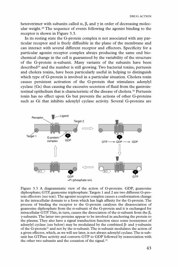
Chapter2 Operating Principles
Rev.A 2-19
2.2.1 C206 PSB/PSE Power Supply Board
C206 PSB/PSE board is a power supply board with a RCC switching regulator, which generates +42VDCfor drive part and +5VDC for logic part to drive the printer. One of the major characteristic of this board isthat the same secondary switch is used as Stylus Color series printer. By using this switch, the followingdifference can be seen as superficial phenomena compared with products applied with primary switchmethod, such as Stylus Color IIs, II and Stylus 800/1000 series printer. The table 2-12 below showsapplication of voltages generated by C206 PSB/PSE board.
1) Even if the switch is turned off during the middle of printer operation, since the drivingpower is turned off after the carriage goes back to the carriage lock position,the possibility of clogging ink nozzle will be decreased.
2) If the switch is turned off when the papers in the printer are still being carried except forthe papers in the hopper, the same operation mentioned above is performed and thedriving power is turned off after the paper is completely ejected.
Table 2-12. Application of DC VoltageVoltages Application
+42VDC � CR Motor� PF/Pump Motor� Head driving power supply
+5VDC � Power supply for logic control� System control signal� Sensor circuit power supply voltage� LED panel drive power supply� Nozzle selector control signal power supply voltage
Figure 2-18 shows block diagram of C206 PSB/PSE board. The process from the input of AC100V to theoutput of 42 V DC and 5 V is explained below.
1) Regardless of the state of power switch(On or OFF), the voltage is always applied in the primaryside of the power supply board from the moment or at the state that AC-plug is plugged in.At this time, F1 plays a role of preventing AC100V from coming into the F1.L1 and R1-R2 also prevent high harmonic wave noise generated in the RC circuit filter which consistof C1∼C4 and R1∼R2 from going out, and eliminate the noise from outside here.
2) The AC is full-wave rectified by diode bridge DB1, and converted to 2 x AC in voltage by smoothingelectrolytic capacitor C11.
3) The pressured up direct current makes Q1 On through the starting resistor R31 and starts the primaryside of the circuit.
4) When the primary side is On state, the energy(current) led by the electromagnetic induction throughthe trans (T1) does not flow to the secondary side since the diode(D51) on the secondary sideis installed in the opposite direction.
5) When the energy which is charged in the trans is reaching the saturated state, the voltage whichmakes the Q1 On becomes weak gradually. At the point that this voltage drops at thecertain voltage, C13 absorbs the current in the opposite direction and Q1 is quickly shut off bythe resulting sharp drop.
6) When the primary side is turned off, the energy charged in the T1 is opened according to thediode(D51) direction which is installed on the secondary side. Basically, 42 V DC is outputby these circuit operations and the number of T1 spiral coil .
7) +5VDC is generated by pressured down this +42VDC as power supply. IC51 pressures down the+42VDC and generates precise +5VDC by chopping off the output, forming the standard santooth wave form by the outer RC integration circuit.

EPSON Stylus Color 400 Service Manual
Rev.A2-20
The C206 PSB/PSE board has various control circuits to stop output if malfunction on the power supplyboard, on the main board or on the duty of printer mechanism happen. Following explains each controland protection circuits.
1) +42V Line Constant Voltage Control Circuit:The output level of the +42V line is monitored by a detection circuit consisting of seven Zener diodes.This circuit prevents voltage from dropping for constant output voltage.
2) +5V Line Over voltage Protection Circuit: This protection circuit is in the same line as +42V over voltage protection circuit is located. The output voltage level of the +5V line is monitored by a Zener diode. This circuit shuts down the circuit
operation forcefully when the voltage level exceeds +9V.
3) +42VDC Line Over voltage Circuit: This circuit is in the same line as +5V line over voltage protection circuit is located. The output level is monitored by two Zener diodes. If the voltage level exceeds +48VDC, this circuit stops circuit operation forcefully.
4) +5V Line Constant Voltage/Constant Current Control Circuit: The output current is monitored by a +5VDC generation switching control IC(IC51), which also monitors the output voltage. This information is input to the internal comparator and stabilizes +5V line. Also, operation of the secondary side switch is explained below.
1) When the power is turned on, Q1 repeats ON/OFF automatically along with the increase anddecrease of energy on the trans coil at the primary side. While the power is being on, PSCsignal is input to the power supply board from the C206 main board.
2) This signal turns Q84 on and it becomes possible to discharge energy between 8-9 of T1.At this time, even if the power is turned off, the electrolytic capacitor keeps Q84 on for a while.By this electrolytic capacitor, output is hold at least 30 seconds even after the power is turned off.This time helps the printer to complete the P-Off operation.
F1
L1,R1-R2 C1-C4
DB1 C11
Q1
T1
C84,Q84
Q2,Q3,
TRANS
+5V generationC51
PC1
+42VDC
+5VDC
Q31,PC1
AC100V
D51
+42V overvoltageprotection circuit
+5V overvoltageprotection circuitDelay circuit
Power OFF
ZD52,87 ZD53
ZD81-86,ZD51
PSO Signal
Filter Circuit
Prevention of current flow
Rectifier circuit
Main switchingcircuit
Smoothingcircuit
Feedback
circuit
Photo coupler
circuitSmoothing
+42V constantvoltage control
(IC51)
circuit
circuit
Full Wave
Figure 2-18. C206 PSB/PSE Board Block Diagram

Chapter2 Operating Principles
Rev.A 2-21
2.2.2 C206 MAIN Board
Various DC voltage generated on the C206 PSB/PSE board is added various signals in order to drive theprinter function on the C206 main board, and the drive of CR/PF(Pump) motor and printing head isperformed. This control board consists of system part and drive part. In the system part, there areformation and controls of various signals in order to drive the CR/PF(pump) motor, sequence controlby input from the sensor circuit, and also output of signal to select appropriate nozzle for the printinghead. On the other hand, the drive part has constant current drive by the driver IC for the CR/PF(pump)motor drive and trapezoidal wave form circuit for head drive.
[CPU]The C206 main board is controlled by a 16-bit CPU(TMP95C061AF) running at 25Mhz. Gate arraymanages most of controls and monitors. Likewise the Stylus Color, the D-RAM is applied for RAMwhich is used as work area for receiving data and developing the data and CPU manages its controlsuch as CE, RAS/CAS controls.
[Gate Array]E05B44 controls following functions.
� Motor control : Each motor performs data transmission(W1-2 phase) that motives Micro-Step.
� Head voltage control: In the ink jet printers, drive voltage wave form(trapezoidal wave form) in order to drive PZT is formed in the various shapes according to the
types of the printers.Therefore, it is necessary to form appropriate drive form for each head.Head voltage control forms necessary wave form for each control
signals and outputs them.� EEPROM control: The correction value to eliminate the error of each printers at the
production process is installed in the fixed address of IC. When the power is turned off, the contents set by users is
written instantly, and is red to the RAM when the power is turned on.� Sensor Data: The sensor detects information at the various conditions, which is
necessary for the printer operation. The gate array recognizessignals and changes over to the next control.
TPM 95C061(IC1:CPU)
SN75LBC775(IC16 Transceiver)
E05B44(IC2: Gate Array)
M5M411664(IC4:D-RAM)
PROM4M(IC3:EPROM)
Panel I/F
Head Common Drive
CR/PF Motor Drive
Centornics I/F
Serial I/F
DRAM Control
Sensor Circuit
EEPROM (IC11)
Head Temperature
Timer (IC5)
System
PowerH8D2813D(IC6)
to A
to B
From A
From BLB1845(IC14)
LB1845(IC15)From B
Print Head
Carriage Motor
PF(Pump) Motor
C206 Main Board
Figure 2-19. C206 Main Control Board Block Diagram

EPSON Stylus Color 400 Service Manual
Rev.A2-22
� Timer Data: The timer IC that uses lithium battery as power source monitors how longthe power is off. When the power is turned on, it is changed to appropriatecleaning level according to the time that the power is off.
� Serial Data: The gate array receives serial data through the transceiver IC.� Parallel I/F control: With the use of IEEE1284 Nibble mode, it became possible not only to
receive the data from the host but also to return various information whichthe printer possesses to the host.
[Common Driver IC]The trapezoidal wave form circuit for head drive is became to HIC from the previous discreate structure.Because of this, it is not necessary to adjust the adjustable VR on the board during production process.Various electric charge/discharge control signals are all processed in the HIC.
[CR/PF Motor Drive Circuit]Constant current drive is performed by the HIC. Out of this, only CR Motor is controlled for Micro-Stepcontrol and HIC becomes possible to flow the appropriate current value at each steps. (PF Motor hasonly 1-2, 2-2phase drive method). Also, bipolar drive is performed on the 4 cables individually. Followingpages explain each major control circuit.

Chapter2 Operating Principles
Rev.A 2-23
2.2.2.1 Reset Circuits
The reset circuit prevents the CPU from running away, which is caused by the unstable voltage in thelogic line during the power ON/OFF operation. Also, this circuit monitors level of power voltage at the overloading or malfunction on the circuit and manages the printer to operate normally, keeping the damage tothe printer minimum during the abnormal situations. On the C206 main board, 2 ICs are mounted ; IC formonitoring the voltage level (logic line) and IC for monitoring the voltage level (power line) and bothare monitored by the gate array and CPU.
The figure below shows reset circuit block diagram with explanation on the next page.
[PST592(IC8)]The actual operation of the circuit is to keep outputting Low signal until +5V line goes up to +4.2Vwhen the power is on, and to cancel the reset signal with output of High signal when the voltage goes upmore than 4.2V.
[M51955(IC9)]This IC also performs as monitor on the power line same as the reset IC for logic described above.High/Low is judged at the 33.2V.
[Relation between IC8 and IC9]Reset signal which is low and output by IC9 is input to the CPU and gate array and system reset operationis performed. Also, this signal is detected on the IC9(IC for reset monitor, power line) and outputs thesame Low signal towards CPU/NMI terminal by being input to NC5.
PST592D(IC8)
Vcc
Vout
NRES
GND
+5V
C47R138
+5V
R1
/RESET
TMP95C061(IC1)
P85
E05B44(IC2)
/RESET17430
16
1
2
3
4
M51955B(IC9)
VCC2
4R6
+42V
R10
+5V
NC8
NC5
OUT
/NMI10
P8415
5
6
7
8
GND
IN
Figure 2-20. Reset Circuit Block Diagram

EPSON Stylus Color 400 Service Manual
Rev.A2-24
2.2.2.2 Sensor Circuits
The following sensor circuits are mounted in the Stylus Color 400 and selects appropriate operationsbased on the returned information.
� ASF Sensor: An ASF sensor detects the position of return lever when the power is (Photo) turned on, and causes the paper to be picked up by the pick up roller
from the normal initial condition. (Refer to section 2.1.1.3 for detail.)
� PE Sensor: A PE sensor determines if there is paper in the printer. Based on the(Photo) signal form this sensor, a particular paper edge treatment such as Micro-weave printing is performed.
� HP Sensor: A HP sensor detects the carriage home position.(Photo) It is used for managing printing position and cleaning, etc.
� Thermistor Sensor: A thermistor sensor keeps stable printing quality, changing PZT drivevoltage(VH) slightly according to changes of environmentaltemperature.
� Cartridge Sensors: Cartridge sensors are built into the Bk, CMY cartridge on the carriage unit respectively to determine if the cartridge is installed or not when itis exchanged or the power is turned on. In case of Stylus Color 400, the counter is reset at every time the cartridge is removed.
The figure below shows sensor circuit. Out of the data such as EPW with IEEE 1284 Nibble modeto be returned to the host, the data to indicate ink consumption is calculated and managed by thecounter of the firmware. Therefore, it is omitted here.
CN11
CN4
CN5
1
2
3HPV
GND
HP
PEV
GND
PE1
2
3
1
2
3ASFV
GND
ASF
+5V+5V
+5V
3
2
1
E05B44(IC2)
SW8
SW7
SW6
SW5
SW4
CCO(198)
BCO(200)
PE(202)
HP(204)
ASF(206)
CN8
2CCO
BCO1
CN8THM3
AN0
TMP95C061(IC1)
+5V
20
18Vref
AGND17
Figure 2-21. Sensor Circuit Block Diagram
Chapter2 Operating Principles
Rev.A 2-25
2.2.2.3 EEPROM Control Circuits
The EEPROM of Stylus Color 400 has following contents. Gate array E05B44(IC2) controls operations ofreading data when the power is on and writing data when the power is off.
� Ink consumption(Bk, CMY)� CL counter(Various cleaning operations that are previously done are memorized)� Destination information� Information of various adjustment values(Bi-D, VH voltage, etc.)� CPSI pass word� Other various setting values by the user
EEPROM is connected to the Gate array by 4 lines and performs following functions.The figure below shows EEPROM control circuit.
� CS : Chip selection signal� CK : Data synchronism clock pulse� DI : Data writing line(serial data) at power off.� DO : Data reading line(serial data) at power on.
+5V
CS
CK
DI
DO
1
2
3
4
127
128
126
125
ECS
ECK
EDO
EDI
93C46(IC11) E05B44(IC2)
VCC
ORG
GND
8
6
5
Figure 2-22. EEPROM Circuit Block Diagram
EPSON Stylus Color 400 Service Manual
Rev.A2-26
2.2.2.4 Timer Circuit
The lithium battery is mounted on the C206 main board and calculates how long the printer is not used.The timer IC(IC5) starts counting with oscillation motivated by the CR1 using this battery as a powersource. The figure below shows connection of the Timer circuit.
The followings explain about operation of this circuit.
� When the printer is on, power is supplied to the Timer IC by applying +5V quickly throughthe D1.
� This power is also used for the power to oscillate the outer CR1. The oscillation wave form isinput to XIN terminal.
� Since the oscillation wave form of CR1 is analog wave form, it is processed into thepulse form in the Timer IC.
� When the printer is turned on, the Timer IC outputs power off time as serial data to the gatearray.
� Once the printer is turned off, 3VDC of BAT1(lithium battery) is supplied as power source forhe Timer IC through D7.
� Since +5V at the power on is higher than +3V of the lithium battery, the power is not beingconsumed from the lithium battery.
2.2.2.5 DRAM Control
In the Dynamic RAM control, output and formation of CAS and RAS control signals become necessaryin addition to the output of CS signal. The CPU TMP95C061AF not only controls that but also performthe output of CS signal of P-ROM. Refresh timing is performed in the CAS Before RAS.
TCE
TIO
TCLK
TDATA
123
122
121
124
CS
/SCK
SIO
1
6
7
VDD
XOUT
XIN
VSS
CR1
+5V
BAT1D7
D1
+5V
E05B44(IC2)
S-3510ANFJ(IC5)
8
2
3
4
Figure 2-23. Timer Circuit Block Diagram

Chapter2 Operating Principles
Rev.A 2-27
2.2.2.6 Print Head Control Circuit
The print head control circuit of Stylus Color 400 has following characteristics.
� Common wave form circuit became one HIC.� Slight vibration mode is added.(when the CR motor is accelerating)� High speed drive 14.4Khz (trapezoidal wave form� Big Nozzle configuration (resolution in the vertical direction)90dpi
(However, black nozzle is 2 lines structure)
Also, Stylus Color 400 does not have Micro-dot control as dot shooting control, but there are two types;Normal-dot and Normal dot-2dot. Normal-dot-2dot was called Dual Firing in the Stylus Color IIs/820.These setting/change are controlled automatically by setting of the printer driver that is determinedby the user. The followings are required conditions to perform the normal-dot 2-dot.
� At the OHP sheet setting (360X360 dpi)� At the ordinary paper and resolution 360X360 dpi setting
The control circuit is considered as 2 divided parts; 1) trapezoidal wave form generation circuit(common drive circuit) to drive PZT in the head, and 2) Nozzle-selector drive circuit to determinewhich nozzle should be used. The Nozzle-Selector is attached to the head unit just like the previousmodels. The common drive circuit is sumed as one HIC and mounted on the C206 main board.
[Common drive circuit]
The shape of trapezoidal wave form will be different according to the printing operation, slight vibrations atthe non-printing nozzle and waiting condition. However, IC6(H8D2813) generates all wave forms as drivewave forms by resistance(electric) welding control of common voltage drive control signal that is outputfrom the IC2(E05B44) in the figure above.
Table 2-13. Specifications of H8D2813 OperationItem Contents
Drive Power Voltage 42 ± 5 %Starts supplying after 5V rises and be stabilized./ Stopssupplying before +5V drops.
Final drive element 2SC3746(for charging), 2SA1469(for discharging)Operation at the Reset Off on the both charging and discharging sides.
Supplies drive power source.This common voltage trapezoidal wave form can be observed anytime after the +5V rises even if there isprinting data or not. (Q7:3-pin,Q9:3-pin and GND on the C206 main board)
F1
+42V+5V
H8D2813D (IC6)
VMVCC
E05B44 (IC2)
CTC
DTB
GND1GND2
192021
161718
CN8
CHG
KC1
ND1ND2MD1
MD2DATADATA/STBCLK
CHG
KC1
ND1ND2MD1
MD2DATADATA /STB
CLK
Figure 2-24. Print Head Control Circuit Block Diagram

EPSON Stylus Color 400 Service Manual
Rev.A2-28
[Nozzle Selector Drive Circuit]
In order to motivate the print head to carry out printing, it is necessary to transmit the printing data to theappropriate nozzles, which becomes direct signals to drive PZT. This data transmission is performedby the serial method, however the data output for each black and CMY head is transmitted by the parallelmethod. The figure below shows data transmission circuit.
CLK(Clock) pulse considered as source of serial communication is commonly used for both black andCMY. The serial data transmits data as 64-Clock unit, synchronizing with this pulse. After the datatransmission of 64-Clock is completed, LAT(Latch) signal is activated and is hold temporarily in theIR2C72C. At this time, since the number of nozzle for Color head is fewer(21-nozzle) and different fromthe ones for black head, 0 is transmitted forcefully for the data for 43 nozzle (64-21=43).
VH
COM
NCHG
CLK
SI1
SI2
LAT
THM
CN8
SI0(for black)
SI1(for colr)
SCLK
LAT
XCHG
COM
VHV
VD1/2
Gate ArrayE05B43(IC2)
U101IR2C72C
Black DataLatch
Color DataLatch
Black Nozzle
Color Nozzle
Figure 2-25. Nozzle Selector Circuit Block Diagram

Chapter2 Operating Principles
Rev.A 2-29
After the data transmission by the nozzle selector(IR2C72C) is completed and a certain time passes,trapezoidal wave form generated by the common drive circuit once sends electric current to the PZTfor the proper nozzles which are determined in the nozzle selector circuit. This motivates PZT andejects the ink in the cavity. The figure below shows normal dot data transmission timing in order to form1 dot.
Figure 2-26. Timing Chart at the Generation of Normal Dot
EPSON Stylus Color 400 Service Manual
Rev.A2-30
2.2.2.7 PF (Pump) Motor Drive Circuit
IC15(LB1845) is used for driving PF(Pump) motor. In the IC, Bi-pola drive PWM current control typeis performed, making it possible to provide stable current to each phase of motor.Also, it makes possible to change over the reference voltage as drive current settings by making3 combinations(100%, 66% and 33%), using 4 current setting ports(input). (Refer to 2.1.1.3 for motorand details about sequence) However, firmware does not drive Micro-step in the Stylus Color 400.The figure below shows connection diagram of PF(Pump) motor drive circuit.
Unlike using Uni-Pola drive, there is no cable for GND in the motor since Bi-Pola drive is performed in thePF motor.(Refer to figure2-10 since carriage motor interior connection diagram has the same connectionas the PF motor’s phase connection. This helps to understand the reason why the direction ofcurrent is controlled freely in each phase by the combinations of high/low control signals.
The current control is performed by output port(46∼49 pin) of E05B44(IC2), its outer resistancecircuit and driver IC(LB1845). First, firmware possesses 16 ways of current values as current tableout of combinations made by 5 resistance which are connected to the output ports(46∼49 pin) in thegate array. On the other hand, signals which are output by combination of these resistance’s on/offare input in the 26 and 17 pins. HIC is driven at the same standard voltage for each A and B phase.
Actual on/off control to send electricity through the motor is performed by the process that SEN1 andSEN2 terminals (2 and 13 pin) detect the input signal from the gate array which is monitored by theinterior comparator, confirm the current that actually flew the phase as current value again andperform the feed back to the on/off. The figure below shows relation between input signal to thedriver IC and motor control.
+42V
Figure 2-27. Connection Diagram of PF(Pump) Motor Drive Circuit
E05B44(IC2)Gate Array
+5V
+42V
RS
R1 R2 R3 R4
Ra
Rb
UDN2917(IC14,IC15)
In case of PM motor,same reference voltageis input to UDN2917 forboth phase A and B, butdifferet reference voltageis set individually forphase A and B, in case of CR motor.
Note:
It varies load resistanceby the control signal andchanges the ratio of partialpressure.
If feeds back the currentthat actually flew in thecoil to the comparator.
Figure 2-28.Motor Drive
Chapter2 Operating Principles
Rev.A 2-31
2.2.2.8 CR Motor Drive Circuit
In the CR motor, the same LB1845(IC15) as the PF motor has is used. In the IC, Bi-pola drive PWMcurrent control type is performed, making it possible to provide stable current to each phase of motor.Also, it makes possible to change over the reference voltage as drive current settings by making3 combinations(100%, 66% and 33%), using 4 current setting ports(input). (Refer to 2.1.1.3 for motorand details about sequence) However, firmware performs Micro-step driving in the Stylus Color 400.The figure below shows carriage motor drive circuit.
Unlike using Uni-Pola drive, there is no cable for GND in the motor since Bi-Pola drive is performed in theCR motor.(Refer to figure2-10 since carriage motor interior connection diagram has the same connectionas the PF motor’s phase connection. This helps to understand the reason why the direction ofcurrent is controlled freely in each phase by the combinations of high/low control signals.
The current control is performed by output port(46∼49 pin) of E05B44(IC2), its outer resistancecircuit and driver IC(LB1845). First, 10 resistance which are connected to the output port(60∼61pin,63∼70pin) of the gate array divide each current values of phase A and B in the CR motor.The firmware possesses 16 different ways of current values individually as current table out ofcombinations made by 5 resistance which are connected to the output ports(46∼49 pin) in the gate array.On the other hand, signals which are output by combination of these resistance’s on/off are inputindependently in the 26 and 17 pins. HIC is driven at the different standard voltage for each phase A andB.
Actual on/off control to send electricity through the motor is performed by the process that SEN1 andSEN2 terminals (2 and 13 pin) detect the input signal from the gate array which is monitored by theinterior comparator, confirm the current that actually flew the phase as current value again andperform the feed back to the on/off. (Refer to figure 3-31 since it is same as the one of PF motor)
OUT1A
OUT1B
OUT2A
OUT2B
+42V
CRA
CR/A
CRB
CR/B
7
6
9
8
IO1
I11
IO2
I12
22
23
21
20
Vref1
Vref2
SENS1E1
SENS2E2
CRA0
CRA1
CRB0
CRB1
75
76
72
73
77
74CRAPH
CRBPH
25
18PH1
PH2
MTBV0-MTBV4
MTAV0-MTAV4
E05B44(IC2) LB1845(IC15)
Current decisionresistor
Figure 2-29. Connection Diagram CR Motor Drive Circuit
Chapter 3Disassembly and Assembly
3.1 OVERVIEW ............................................................................................................3-1 3.1.1 Precautions for Disassembling the Printer.......................................................................... 3-1
3.1.2 Tools .................................................................................................................... .................... 3-2
3.1.3 Specification for Screws................................................................................................. ....... 3-2
3.1.4 Service Checks After Repair.............................................................................................. .... 3-3
3.2 Disassembly Procedures .....................................................................................3-4 3.2.1 Removing the Housing ..................................................................................................... ..... 3-5
3.2.2 Removing the Board Assembly............................................................................................. 3 -6
3.2.3 Removing the Operation Panel ............................................................................................. 3-8
3.2.4 Disassembling the Printer Mechanism................................................................................. 3-9 3.2.4.1 Removing the Print Head Unit ................................................................................... 3-9 3.2.4.2 Removing the Absorber Tray Assembly ;A...............................................................3-11 3.2.4.3 Removing the Pump Assembly and Cap Assembly................................................ 3-12 3.2.4.4 Removing the CR Motor Assembly ......................................................................... 3-14 3.2.4.5 Removing the PF Motor Assembly.......................................................................... 3-16 3.2.4.6 Removing the ASF Assembly.................................................................................. 3-18
3.2.4.6.1 Removing the Paper Feed Roller Assembly ................................................ 3-19 3.2.4.6.2 Removing the Right and Left LD Roller Assembly ....................................... 3-20
3.2.4.7 Removing the Carriage Assembly........................................................................... 3-21 3.2.4.8 Removing the PF Roller Assembly.......................................................................... 3-23 3.2.4.9 Removing the PE Paper Detector Assembly........................................................... 3-25 3.2.4.10 Removing the HP Detector.................................................................................... 3-26

Chapter3 Disassembly and Assembly
Rev. A 3-1
3.1 OVERVIEWThis section describes procedures for disassembling the main components of EPSON Stylus Color 400.Unless otherwise specified, disassembly units or components ca be reassembled by reversing thedisassembly procedure. Therefore, no assembly procedures are included in this section. Precautions forany disassembly or assembly procedure are described under the heading “WORK POINT”. Anyadjustments required after disassembling the units are described under the heading “REQUIREDADJUSTMENT”.
3.1.1 Precautions for Disassembling the PrinterSee the precautions below when disassembling or assembling EPSON Stylus Color 400.
� Disconnect the power cable before disassembling or assembling the printer.
� Wear protective goggles to protect your eyes from ink. If ink gets in your eye, flush the eye withfresh water and see a doctor immediately.
� If ink comes into contact with your skin, wash it off with soap and water. If irritation occurs,contact a physician.
� A lithium battery is installed on the main board of this printer. Be sure to observe the followinginstructions when serving the battery:• Keep the battery away from any metal or other batteries so that electrodes of the opposite polarity do not come in contact with each other.• Do not heat the battery or put it near fire.• Do not solder on any part of the battery. (Doing so may result in leakage of electrolyte from the battery, burning or explosion. The leakage may affect other devices close to the battery.)• Do not charge the battery. (An explosion may be generated inside the battery, and cause burning or explosion.)• Do not dismantle the battery. (The gas inside the battery may hurt your throat. Leakage, burning or explosion may also be resulted.)� Do not install the battery in the wrong direction. (This may cause burning or explosion.)
� Danger of explosion if the battery is incorrectly replaced. Replace only with the same or equivalenttype recommended by the manufacture. Dispose the used batteries according to government’slaw and regulations.
���������
Risque d’explosion si la pile est remplacée incorrectment. Ne remplacer que par une pile du mêmetype ou d’un type équivalent recommandé par le fabricant. Eliminer les piles déchargées selon les loiset les règles de sécurité en vigueur.
� Never remove the ink cartridge from the carriage unless manual specify to do so.
� When transporting the printer after installing the ink cartridge, be sure to pack the printer for transportation without removing the ink cartridge.
� Use only recommended tools for disassembling, assembling or adjusting the printer.
� Apply lubricants and adhesives as specified. (See Chapter 6 for details.)
� Make the specified adjustments when you disassemble the printer. (See Chapter 4 for details.)
WARNING
CAUTION

EPSON Stylus Color 400 Service Manual
Rev. A3-2
� When assembling, if ink cartridge is removed and needs to be installed again, make sure to install new ink cartridge because of following reasons; Once the ink cartridge mounted on the printer is removed, air comes into and becomes bubbles in the cartridge. These bubbles clog ink path and cause printing malfunction. If an ink cartridge which are still in use is removed and is installed again, ink quantity will not be detected correctly since the counter to check ink consumption is cleared.
� Because of the reasons above, make sure to return the printer to the users with new ink cartridge installed.
3.1.2 ToolsTable 3-1 lists the tools recommended for disassembling, assembling, or adjusting the printer.Use only tools that meet these specifications.
Tool Purchasable CodePhilips Screw Driver No.2 Yes B743800200Philips Screw Driver No.1 Yes B743800400
Tweezers Yes B741000100Hexagon Box Driver
(Size:5.5mm)Yes B741700100
3.1.3 Specification for Scre ws
Table 3-2 below shows specifications for screws. During assembly and disassembly, make sure thelocations for fixing screws and screw types, referring to the table below.Also, described screw number in the text corresponds to the No. in the table.
No. Body Name Size1 +Bind, S-tight M3X6
2 +Bind, S-tight M3X103 +Bind, P-tight
(CBP tight)M3X6
4 +Bind, P-tight(CBP tight)
M3X10
5 +Bind, P-tight(CBP tight)
M3X8
6 +Pan head(CP)
M3X4
7 +Bind, S-tight, Sems R2(CBS Sems)
M3X6
CAUTION
Table 3-1. Recommended Tools
Table 3-2. Screw Identification
Chapter3 Disassembly and Assembly
Rev. A 3-3
3.1.4 Service Checks After RepairBefore returning the printer after service, use the check list in Table 3-3, which provides a record tomake servicing and shipping more efficient.
Category Component Item to check Is Check required?Self-test Is the operation normal? �Checked / �Not necessaryOn-line test Was the on-line test successful? �Checked / �Not necessaryPrint head Is ink ejected normally from the all
nozzles?�Checked / �Not necessary
Carriagemechanism
Does the carriage move smoothly? �Checked / �Not necessary
Any abnormal noise duringmovement?
�Checked / �Not necessary
Any dirt or obstacles around theaxis of carriage guide?
�Checked / �Not necessary
Printer units Is the CR motor at the correcttemperature(not over heating)?
�Checked / �Not necessary
Paper feedingmechanism
Is paper fed smoothly? �Checked / �Not necessary
Does the paper get jammed? �Checked / �Not necessaryDoes the paper get skew duringpaper feeding?
�Checked / �Not necessary
Are papers multi fed? �Checked / �Not necessaryDoes the PF motor get overheated? �Checked / �Not necessaryAbnormal noise during paperfeeding?
�Checked / �Not necessary
Is the paper path clear of allobstructions?
�Checked / �Not necessary
Adjustment Pointed adjustmentitems
Are adjusted conditions all right? �Checked / �Not necessary
Lubricant Pointed lubricantitem
Is lubrication applied to the pointedlocations?
�Checked / �Not necessary
Is the quantity of lubricationadequate?
�Checked / �Not necessary
Function ROM version Newest version: �Checked / �Not necessaryShipmentpackage
Ink cartridge Is the ink cartridge installedcorrectly?
�Checked / �Not necessary
Protectionconditions duringtransport
Is all the pointed parts firmly fixed? �Checked / �Not necessary
Others Attached items Is all attached items from usersincluded?
�Checked / �Not necessary
Table 3-3. Inspection Check List for the Repaired Printer

EPSON Stylus Color 400 Service Manual
Rev. A3-4
3.2 Disassembly Procedures
The figure below shows procedures for disassembly.
Remove the Housing
3.2.1
Remove the Board Assembly
3.2.2
Remove the operation panel
3.2.3
Remove the Printer Mechanism
3.2.4
Refer to
Removethe Print Unit
3.2.4.1
Removethe Absorber tray,Assembly;A
3.2.4.2
Remove the Pump Assembly,Cap Assembly
3.2.4.3
Remove the CRMotor Assembly
3.2.4.4.
Remove the PFMotor Assembly
3.2.4.5
Remove the ASFAssembly
3.2.4.6
Remove the CRAssembly
3.2.4.7
Remove the PFRoller Assembly
3.2.4.8
Remove the PEPaper Detector Assembly
3.2.4.9
Remove the HP Detector
3.2.4.10
Remove the LDRoller Assembly(Right/Left)
3.2.4.6.2
Remove the PaperFeed RollerAssembly
3.2.4.6.1
Figure 3-1. Flow Chart of Disassembly

Chapter3 Disassembly and Assembly
Rev. A 3-5
3.2.1 Removing the Housing
Since the printer mechanism itself structures the bottom part, the printer mechanism appears just byremoving the housing.
1. Open the printer cover and turn the PG adjustment lever towards (+) side.2. Remove 4 screws(No.2) securing the housing, and remove the housing.
Uplift and remove the housing, pulling it towards you.(Since it collides with carriage)
WORK POINT
Housing
(No.2)
Figure 3-2. Removing the Housing

EPSON Stylus Color 400 Service Manual
Rev. A3-6
3.2.2 Removing the Board Assembly
Since the main board(C206 Main) and power supply circuit board(C206 PSB) are built in differentbracket from the printer mechanism, remove the whole bracket from the printer mechanism.
1. Remove the housing.(Refer to 3.2.2)2. Remove the 5 screws(No.1) securing the “M/B Shield plate” on the printer mechanism.3. Pull out the “M/B Shield Plate” a little bit and remove cables which are hung on the A and B holders
as you can see in the figure below.Then, take all cables out of connectors on the C206 main board. (CN11 black, CN4 yellow, CN5 white,CN3 black and CN8 FFC)
4. After removing all the cables from the C206 main board, detach the “Shield plate M/B” completely from the printer mechanism.5. When removing each board unit from the “M/B Shield plate”, remove each screw securing each units and shield plate. [C206 Main: 10screws (7 No.1 screws, 3 No.6 screws), C206 PSB/PSE: 4screws(No.1)] Refer to the next page for the figure.
Also, when removing the power supply board(C206 PSB), disconnect and also removethe cable connecting to the Main board (CN6, 7 and 10 with lock device).
� Since connector CN 6,7 and 10 are the connector with lock device, make sure to release the lock before removing the cable. Also, make sure to lock when installing these cables.
� When connecting cables to the connectors, each cable never cross each other in this printer. So, if there are two connectors sitting next to each other, the cable from right should be connected to the right connector and the cable from the left should be connected to the left one.
WORK POINT
[Cable Holder A and B]
A
M/B Shield Plate (No.1)
(No.1)(No.1)
B
Figure 3-3. Removing the M/B Shield Plate

Chapter3 Disassembly and Assembly
Rev. A 3-7
M/B Shield plate
Power Supply Board
(C206 PSB)
Main Board
(C206 Main)
(No.6)
(No.1)
(No.1)
Figure 3-4. Removing the Boards

EPSON Stylus Color 400 Service Manual
Rev. A3-8
3.2.3 Removing the Operation Panel
1. Remove the housing. (Refer to 3.2.1)2. Remove two screws (No.1) securing the operation panel and disconnect the operation panel from
the printer mechanism.3. Remove one screw (No.1) and detach the left panel housing.4. Remove two screws (No.3) securing the panel board assembly and take C206 PNL board out of
the panel assembly.5. Disconnect the FFC from the connector on the C206 PNL board.
Removing the operation panel also disconnects the stacker assembly, since the operation panel holdsthe stacker assembly.
WORK POINT
Stacker Assembly
Left Panel Housing
Panel Assembly
Panel Shield Plate
Panel Board Assembly
(No.1)
(No.3)
(No.1)
Figure 3-5. Removing the Operation Panel

Chapter3 Disassembly and Assembly
Rev. A 3-9
3.2.4 Disassembling the Printer Mechanism
Since Stylus Color 400 does not have the lower housing, the printer mechanism part should be alreadyappeared by now. Therefore, this section explains procedures for disassembling the major parts or unitsof printer mechanism.
3.2.4.1 Removing the Print Head Unit
1. Remove the housing. (Refer to 3.2.1)2. Rotate the flat gear 67.2 towards yourself (front) and release the carriage lock mechanism.
Then move the carriage to the left edge.3. Take both black and color ink cartridges out of the print head unit.4. Remove the blue covers for black and color ink cartridge from the carriage assembly.5. Remove the torsion spring 49 and one screw(No.3) and take the fastener head out.6. Remove the FFC being placed on the carriage assembly, and take the print head unit
out of the carriage.7. Disconnect the FFC from the connector on the drive board built in the print head unit.
� Make sure that earth board is installed to the carriage correctly. (There are 2 pins to determine the location.)
� When you built the print head into the carriage, make sure that a pin to determine the location on the carriage side is put into the notch of the print head.
� Since the ink cartridge once taken out can not be used again, be sure to install a new ink cartridge when you return the printer to the user.
� When you return the printer to the user, be sure to pack the printer for transportation with a new ink cartridge installed and at the state that carriage is in the home position when the user turns on the power.
� When you replace the print head unit, perform the following adjustment. (Refer to Chapter 4 for more details):
1) Initial ink charge (Refer to Chapter 4 /4.2.2.2)2) Writing VH voltage ID (Refer to Chapter 4 /4.2.2.3)3) Head Angle Adjustment (Chapter 4 /4.2.2.4)
WORK POINT
CAUTION
REQUIRED ADJUSTMENT

EPSON Stylus Color 400 Service Manual
Rev. A3-10
FFC
Fastener Head
Print Head Unit
Figure 3-6.Removing the Print Head
Print Head
Carriage Assembly
Make sure that protrusion
of carriage is in the hole
of the earth board.
This part should be touching the
CR axis receiver.
Make sure that this
protrusion is in the
U ditch of the priht head
side.
Figure3-7.Installing the Print Head

Chapter3 Disassembly and Assembly
Rev. A 3-11
3.2.4.2 Removing the Absorber Tray Assembly ;A
1. Remove the housing. (Refer to 3.2.1)2. Remove the operation panel. (Refer to 3.2.3)3. Remove one screw (No.4) securing “Absorber tray assembly” located on the right side of the printer mechanism.4. On the same right side of the printer mechanism, release the hook securing the absorber tray
assembly ;A on the frame and remove it, pulling it downward.
� When installing the absorber tray assembly ;A, make sure to fix it with spacer tray in the left side of the printer mechanism.
WORK POINT
Spacer Tray
(No.4)
Absorber Tray Assembly;A
Figure 3-8. Removing the Absorber Tray Assembly ;A
EPSON Stylus Color 400 Service Manual
Rev. A3-12
3.2.4.3 Removing the Pump Assembly and Cap Assembly
1. Remove the housing .(Refer to 3.2.1)2. Remove the operation panel. (Refer to 3.2.3)3. Remove the absorber tray assembly ;A. (Refer to 3.2.4.2)4. Loose two screws located on the edges of the paper eject frame assembly and float the paper eject
assembly.5. Rise the printer mechanism toward ASF side so that you can see the bottom of the printer mechanism.6. On the right side of frame, remove a hook holding the cap assembly and release two peaking
attached to the frame, uplifting the right side of cap assembly, then take it out towards the bottomof the printer mechanism. However, the cap assembly is still connected to the pump assembly witha ink tube at this point. (Refer to figures on the next page.)
7. Remove two screws(No.5) securing the pump assembly to the frame. (Refer to figures on the nextpage.)
8. Release a hook securing the pump assembly to the frame and remove the pump assembly,moving it toward right direction. (Refer to figures on the next page.)
� Do not damage the rubber part (black square) of the cap installed in the cap assembly.(If it gets damaged, it will not be able to attach closely with surface of the print head and may cause malfunction of operation.)
� When you deal with cleaner head built in the pump assembly for replacing, be careful about following points.• Do not touch the cleaner head with bare hands. Use gloves or tweezers.• Do not let the cleaner head attach with oil or grease.• When installing the cleaner head, the rubber side(darker black side) should be set toward on the right side of the frame.
� When installing the pump assembly, do not tighten the screw more than necessary torque.
� Since the spring is included in the combination of gears in the pump assembly, be careful not for the parts being popped out during disassembly and assembly.
� When assembling, be careful not to crush or leave any stress on the ink tube connecting between pump assembly and cap assembly.
� After installing the pump assembly, make sure that the cleaner parts can move front and back by rotating the gear 67.2.
CAUTION
WORK POINT

Chapter3 Disassembly and Assembly
Rev. A 3-13
Loosen screws on the rightand left sides and float thePaper eject frame assembly.
Release three hooksfrom the interior of the right frame assembly.
Pump Assembly
Cap Assembly
Release a hook from the back of the printer mechanism andremove two protrusions fromthe subframe.
(No.5)
Figure 3-9. Removing the Cap and Pump Assemblies
Head Cleaner
Order of assembling the pump parts.
Figure 3-10. Component of Pump Assembly

EPSON Stylus Color 400 Service Manual
Rev. A3-14
3.2.4.4 Removing the CR Motor Assembly
1. Remove the housing. (Refer to 3.2.1)2. Rotate the gear 67.2 toward you and release the carriage lock mechanism. Move the carriage
to the center.3. Loose the timing belt by pushing the driven pulley holder and remove the timing belt from the pulley
of the CR motor side.4. Remove two screws(No.1) and take out the CR motor assembly.
After installing the CR motor assembly, make sure that two peaking of motor bracket are in the holesfor determing position on the frame. (Refer to the figure on the next page)
WORK POINT
Driven Pulley Assembly
Timing Belt
Driven Pulley Holder
Compression Spring 19.6
To the Interior of Side Frame
To the Exterior of Side Frame
Figure 3-11. Removing the Timing Belt

Chapter3 Disassembly and Assembly
Rev. A 3-15
(No.1)
Make sure that protrusions of CR frame are in the holes of the frame when installing the CR motor assembly.
Figure 3-12. Removing and Installing the CR Motor Assembly

EPSON Stylus Color 400 Service Manual
Rev. A3-16
3.2.4.5 Removing the PF Motor Assembly
1. Remove the housing.(Refer to 3.2.1)2. Remove the absorber tray assembly ;A. (Refer to 3.2.4.2)3. Remove the following gears located on the left side of the printer mechanism. Refer to the figure
below.� Gear 67.2 (Remove the ring with tweezers or (-) driver. After the ring is removed,
if you try to remove the gear 67.2 holding its edge, the gear may be broken. So, tryto remove it holding the whole gear, slightly pulling it toward you.)
� Combination gear 8.8,21.6� Combination gear 8,14.4� Gear 36
4. Remove 3 hexagon nuts and take the PF motor assembly out.
� When disassembling the PF motor assembly, pull the motor assembly out of the frame a little bit and remove it, sliding it into the bigger hole on the frame. (Refer to the figure next page)
� Be careful for the direction of wires from the PF motor assembly.
� Do not damage or leave any scars on the ditches of the gears during the disassembly and assembly.
WORK POINT
C-Ring
PR Motor Assembly
Hexagon Nut
Compression Spring 0.9
Gear 67.2
Combination Spring 8.8,21.6
Gear 36
Combination Gear8,14.4
Gear 34
Figure 3-13. Removing the PF Motor Assembly

Chapter3 Disassembly and Assembly
Rev. A 3-17
PF Motor(Back side of the frame)
Direction of pullingthe motor lead cable.
Set the pinion axis of PF motorto the bigger hole once and slide it to the smaller hole.
Figure 3-14. Installing the PF Motor Assembly

EPSON Stylus Color 400 Service Manual
Rev. A3-18
3.2.4.6 Removing the ASF Assembly
1. Remove the housing. (Refer to 3.2.1)2. Release the fixed hook from the inside of printer mechanism and remove the gear 34 from the roller
axis of the ASF assembly.3. Take out cables from the cable hook on the printer mechanism and from the hook of the ASF
assembly.4. After removing 2 screws(one No.7 and one CR axis installation screw), remove the ASF assembly,
detaching peaking on the left side of ASF assembly from the frame holes.
� When installing the ASF assembly, make sure that the frame and ASF assembly are attached each other without any space.
� Screws for ASF assembly should be used at the following positions. (Looking from the back of printer) Right :CR axis installation screw Left : Screw No.7 (•{ Bind, S- tight, Sems R2; with plane washers)
WORK POINT
Screw with Washer (No.7)
Gear 34
CR Axis Installation Screw
Make sure that protrusionsin the ASF Assembly are inthese holes on the framewhen installing the ASFassembly.
Figure 3-15.Removing the ASF Assembly

Chapter3 Disassembly and Assembly
Rev. A 3-19
3.2.4.6.1 Removing the Paper Feed Roller Assembly
1. Remove the ASF assembly. (Refer to 3.2.4.6)2. Remove the brake lever, releasing one leg of the torsion spring 41.2 from the hook of the ASF frame.3. Remove the fixing axis bush from the right side of LD the roller axis and hopper lever release.4. Move the left side of paper feed assembly part to the center and remove the cam fixed bush (white
plastic) attached to the left side of LD roller axis.5. Push the LD roller axis to the left and remove the left axis fixed bush after releasing its hook.6. Remove right and left sides of hopper assembly from the peaking of the ASF frame.7. Uplifting the right side of paper feed roller assembly a little bit, push the LD roller axis to the right
and remove it from the left side of the ASF frame.8. Holding the hopper assembly by hand, remove the cam part of hopper assembly from the right holes
of ASF frame.The procedures by here should disassemble right and left roller assembly and hopper assembly.
� During disassembly and assembly of the hopper assembly, do not let the grease on the cam parts attach to the other parts. Wipe it if grease attached to the other parts.
� Be careful for the direction of the hopper lever release, when installing it.
� Make sure that right and left fixed bushes are installed steadily and do not slip off.
� During assembly, attach the cam fixing bush after installing CD roller-axis to the ASF frame.
� When installing right and left paper feed roller assemblies to the LD roller axis, a black paper feed roller assembly comes to right side and the EPSON standard color one comes to left on the axis.
WORK POINT
Hopper Assembly
ASF Frame
Release Hopper Lever
Fixing Axis BushPaper Feed Roller Assembly
Left Fixing Axis Bush
Torsion Spring 41.2
Brake Lever
LD Roller Axis
(Black)
(EPSON standardcolor)
Figure 3-16. Disassembly of ASF Assembly
EPSON Stylus Color 400 Service Manual
Rev. A3-20
3.2.4.6.2 Removing the Right and Left LD Roller Assembly
1. Disassemble the ASF assembly and remove the paper feed roller assembly and hopperassembly from the ASF body. (Refer to 3.2.4.6)
2. Take out right and left compression springs 1.66 from the back of hopper assembly.3. Pull out the cam part of the hopper assembly from the frame hole located on the right side of paper
feed roller assembly.4. Pull out the LD roller axis.
The paper feed roller assembly and hopper assembly should be disconnected by now.5. Release the hook of LD roller assembly at the axis hole of the paper feed roller assembly.
Also, release the fixed hook of cover roller LD and remove the LD roller assembly.
� When installing the LD roller assembly, make sure that the hooks are hung on the paper feed assembly.
� During assembly, when setting the compression spring 1.66 to the spring installation position in the paper feed assembly, hang the spring on the hook temporarily. Also, do not forget to release the hooks of these springs from the holes located on the back of paper feed assembly by rotating the spring. (Refer to the figure below.)
WORK POINT
Compression Spring 1.66
LD Roller Assembly(Right and Left)
Paper Feed Assembly(Right and Left)
LD Roller Cover(Right and Left) +Paper Feed Holder Sheet
During assembly, set the compression spring 1.66 in the position for spring installation of the paper feed assembly and hangthe bent part of the spring on the hook.
Figure 3-17. Disassembly of Paper Feed Roller Assembly
Chapter3 Disassembly and Assembly
Rev. A 3-21
3.2.4.7 Removing the Carriage Assembly
1. Remove the housing. (Refer to 3.2.1)2. Loose the timing belt by pushing the driven pulley holder and remove the timing belt from the pulley
of the CR motor side.3. Take the compression spring 19.6 out of the driven pulley holder.4. Remove the driven pulley assembly from the driven pulley holder with the timing belt. Slide the
driven pulley holder and remove it from the frame.5. Remove the torsion spring hanging on the frame and PG lever. Release the fixed hook of the PG lever
and remove the lever.6. Release the fixed hook of the PG lever support and remove the PG lever support and washer from
the edge of CR guide axis. (Refer to the figure next page.)7. Remove one screw(No.7) and rotate the right parallelism adjustment bush so that it fits to the notch
of the frame, and remove it .8. Remove CR assembly with CR guide axis.
� When disassembling the parallelism adjustment right bush, mark present fixed location of the bush on the frame so that you can omit re-adjustment of gap when assembling.
� When installing the washer, pay attention to its direction.(Convex side should face to the right parallelism adjustment bush side.) Refer to the figure below.
� When installing the PG lever, refer to the figure below.
WORK POINT
PG Lever
PG Support Lever
To the PG Lever
Insert this side to thehole on the right frame.
Elliptic HolesTorsion Spring 63.7
Figure 3-18. Installing the PG Lever

EPSON Stylus Color 400 Service Manual
Rev. A3-22
PG Support Lever
Right Parallelism Adjustment Bush
Washer[Convex side should faceto the bush side, during installation]
Left Parallelism Adjustment Bush
CR Guide Axis
Carriage Assembly
Figure 3-19. Removing the Carriage Assembly

Chapter3 Disassembly and Assembly
Rev. A 3-23
3.2.4.8 Removing the PF Roller Assembly
1. Remove the housing.(Refer to 3.2.1)2. Remove the carriage assembly.(Refer to 3.2.4.7)3. Remove two screws(No.1) on the printer mechanism and disassemble the cable guide board.4. Remove six upper paper guide assemblies, releasing their springs from the hooks of the frame.5. Remove the front paper guide ;B, releasing the hooks. (Refer to next page)6. Remove the paper eject roller assembly, releasing the fixed locks located on the right and left
edge of axis.7. Release the fixed hook located on the left side of PF roller assembly axis and rotate it so that
protrusion of axis(white) and hole for receiving the frame axis can match.8. Slide the PF roller assembly to the right direction and pull it out.
� During disassembly and assembly of upper paper guide assemblies, since one of the upper paper guide assemblies to be installed on the right side overlaps with the PE detector lever, pay attention not to damage the lever.
� Be careful not to damage the hook, during the disassembly and assembly of the front paper guide ;B.
� Be careful not to scar the PF roller assembly during the disassembly and assembly, since its surface is specially coated to improve paper feeding. (black part)
� Be careful not to damage the combination of gears.
WORK POINT
Cable Guide Board
(No.1)
Upper Paper GuideAssemblyLeft Paper Guide
Torsion Spring 117.6
Upper Paper Guide Axis
(6 positions)
Figure 3-20. Removing the Paper Guide Assembly

EPSON Stylus Color 400 Service Manual
Rev. A3-24
Front Paper Guide;B
Eject Paper RollerAssembly
Figure 3-21. Removing the Paper Eject Roller Assembly
PF Roller Assembly
Match the protrusion of PF roller assembly and hole of the frame for holding the axis.
Figure 3-22. Removing the PF Roller Assembly

Chapter3 Disassembly and Assembly
Rev. A 3-25
3.2.4.9 Removing the PE Paper Detector Assembly
1. Remove the housing.(Refer to 3.2.1)2. Release two fixed hooks securing the PE detector assembly from the back of frame and remove the
PE detector assembly, sliding it upward. Remove PE board assembly and PE lever if necessary.
During assembly, make sure that the tip(sensor part) of the detector lever is in the hole of paper guideassembly.
WORK POINT
After releasing two hooks, removethe PE paper detector assembly,sliding it upward.
PE Lever
Torsion Spring 0.22
PE Board Assembly
PE Holder
This side should beinstalled on the frame.
(From back side of the frame)
Figure 3-23. Removing the PE Paper Detector Assembly

EPSON Stylus Color 400 Service Manual
Rev. A3-26
3.2.4.10 Removing the HP Detector
1. Remove the housing. (Refer to 3.2.1)2. Remove the cable from the HP detector and take it out after releasing the fixed hook.
HP Detector
Figure 3-24. Removing the HP Detector
Chapter 4Adjustment
4.1 Overview................................................................................................................4-1 4.1.1 Required Adjustments ..................................................................................................... ...... 4-1
4.1.2 Required Adjustment Tools ................................................................................................ ... 4-1
4.2 Adjustment ............................................................................................................4-2 4.2.1 Parallel Adjustment ...................................................................................................... .......... 4-2
4.2.2 Adjustment by Adjustment Program .................................................................................... 4-4 4.2.2.1 Specification of Adjustment Program ........................................................................ 4-4 4.2.2.2 Initial Ink Charge Operation....................................................................................... 4-5 4.2.2.3 VH Voltage Writing Operation ................................................................................... 4-6 4.2.2.4 Print Head Angle Adjustment .................................................................................... 4-7 4.2.2.5 Bi-D Adjustment ........................................................................................................ 4-9

Chapter4 Adjustment
Rev. A 4-1
4.1 OverviewThis section describes adjustments required when the printer is disassembled and assembled after repair.
4.1.1 Required AdjustmentsStylus Color 400 has following required adjustments.(Refer to table 4-1) Refer to figures for the actualprocedure and perform appropriate adjustment for each exchanged unit.
No. Adjustment Item Conditions1 Parallel Adjustment • When you exchange or remove the Carriage guide shaft.
• When you move the parallelism adjustment bush.2 Initial ink charge • When you exchange or remove the print head.3 VH voltage Writing Operation • When you exchange or remove the print head.
• When you exchange the C206 main board.Note) The values of address are not lost by EEPROM reset operation.
4 Printing Head Angle Adjustment • When you exchange or remove the print head.• When you move the head adjustment lever.
5 Bi-D adjustment • When you exchange or remove the print head.• When you exchange the C206 main board.
No. Content of Operation Adjustment Procedure1 Exchange or Removal of Print head 1)Perform Vh voltage writing operation.
(Only when the print head is exchanged)2)Perform initial ink charge.3)Perform print head angle adjustment.4)Perform Bi-d Adjustment.
2 Exchange of C206 Main Board 1)Perform Vh voltage writing operation.2)Perform Bi-d adjustment.
3 Exchange or Removal of Carriage Unit 1)Perform parallel adjustment.2)Perform print head angle adjustment.3)Perform Bi-d adjustment.
4 Exchange of CR Motor 1)Perform Bi-d adjustment.5 Exchange of Printer Mechanism 1)Perform Vh voltage writing operation.
2)Perform initial ink charge.3)Perform Bi-d adjustment.
4.1.2 Required Adjustment ToolsThe table4-3 below shows adjustment tools for Stylus Color 400.
Table 4-3. Adjustment Tools for Stylus Color 400No. Name Adjustment item Content/Specification1 Thickness Gage Parallel Adjustment Thickness=1.1mm(1.04mm)2 Adjustment Program Each Mechanism Settings Exclusive Program(“J80C10E”)
CAUTION
� Never use the bent (curved or tilted)or rusty thickness gage.
� Erase any dirt, grease or obstacles on the thickness gage before you use it.
Table 4-1. Required Adjustment and Contents
Table 4-2. Operation and Adjustment Item

EPSON Stylus Color 400 Service Manual
Rev. A4-2
4.2 AdjustmentThis section explains specific procedures for each adjustment required for Stylus Color 400.
4.2.1 Parallel AdjustmentWhen exchanging carriage assembly and or removing it along with disassembly of printer mechanism,perform parallel adjustment when assembling and set the standard distance from the surface of the printhead to the paper surface.
CAUTION
� Do not scar the special coated surface of the PF roller assembly(platen) and lib surface of the front paper guide ;B.
� Be careful not to leave any scars or dirt on the surface of the print head. (Never use the rusty or dirty thickness gage. Also, do not push hard the thickness gage to the head.)
[Right Parallelism Adjustment]1. Install the “parallelism adjustment bush” for right and left frame and set them on the peaking of the
upper frame side so that they match with “the standard mark of parallelism adjustment bush”.2. Set the PG lever front. (Gap is small.)3. Move the carriage to the center and set the thickness gage on the fixed position of front paper
guide ;B as you can see in the figure 4-1 on the next page4. Move the carriage to the position that the print head overlaps the thickness gage.
WORK POINT
� Put the thickness gage on the flat side of the lib of the front paper guide ;B.
� When you move the carriage, move it, pulling the timing belt with your hand.
5. Move the right parallelism adjustment to the rear direction until the thickness gage moves with thecarriage when you move the carriage 20mm back and forth in right and left direction.(Gap will be narrowed.)
6. From the state of the thickness gage moves with carriage movement, move the gear for locating theposition of the right parallelism adjustment bush one serration toward you.(Gap will be widen.
7. In the state that PG lever is set front(gap is small) and rear side respectively, move the carriageright and left and make sure that the thickness gage does not move at this time.
[Left Parallelism Adjustment]8. Perform above procedures from 2 to 7 for left parallelism adjustment bush.
[Checking parallelism]9. Perform procedures from1 to 4 again.10. Make sure that the thickness gage does not move along with carriage movement when the carriage
is moved 20mm back and forth.11. In the state that the right parallelism adjustment bush is moved one serration toward rear(Gap will be
narrowed),make sure that the thickness gage moves along with carriage movement.If the thickness gage does not move, perform procedures from 1 again.
12. Move the right parallelism adjustment bush one serration toward you(Gap will be widen).[Fixing Parallelism Adjustment Bush]13. Fix the right and left parallelism adjustment bushes by screws.(No.1 screw each for right and left.)
When completing this adjustment, check the overlap amount of print head and head cleaner.
1. Rotate the gear 67.2 and move the head cleaner to the print rear side.2. Move the carriage next to the head cleaner and make sure that overlap between the tip of the print
head and cleaner head is more than 0.5mm.3. After that, rotate the gear 67.2 and return the head cleaner to the front position.

Chapter4 Adjustment
Rev. A 4-3
Left Side Right SideFront Paper Guide;B
Lib;Avoid 2 libs from left edge Lib; Avoid 2 libs from right edgeCarriage Thickness Gage
PF Roller Assembly Front Paper Guide;B
Put the thickness gage flat on the flat side of lib.
Also, match the center ofthe thickness gage and flat side of the lib.
Figure 4-1. Setting of the Gage at Parallel Adjustment
Frame
PG Lever
Parallelism Adjustment Bush
Standard Position Mark
Front(Gap will be widened)
Rear(Gap will be narrowed)
(+)
(0)
Figure 4-2. Parallel Adjustment
Print Head Side
Cleaner Head
Overlap amount= More than 0.5mm
Figure 4-3. Overlap of Head Surface and Cleaner Brade
EPSON Stylus Color 400 Service Manual
Rev. A4-4
4.2.2 Adjustment by Adjustment Program
In this printer, it is necessary to set correct information for each printer mechanism in order to maintainhomogeneous printing function and quality, erasing dispersion of each printer mechanism’scharacteristics.Therefore, in case that the combination of printer mechanism and main board is changed or the print headis exchanged by repair service, it is required to set and register correct information in the main board,using the exclusive adjustment program.
4.2.2.1 Specification of Adjustment Program
Adjustment Program (Program name:”J80C10E”) is to set various correct values in order to preventdevelopment of malfunction and fluctuation of printing quality and printing function by dispersion ofcomponents and assembly when the printer components are exchanged during the repair service.Basic adjustment procedure by using this program are following.
Main Menu(Item Selection)
Initial Ink Charge
Performance of Initial ink charge process
Head VH voltage ID writing.
Head Angle Adjustment Bi-D Adjustment
*Pattern printing*Confirmation/ Mechanism Adjustment
*Pattern printing*Confirmation/ Input of correct values
Input of appointedVH voltge ID
Figure 4-4. Flow of Adjustment Program

Chapter4 Adjustment
Rev. A 4-5
4.2.2.2 Initial Ink Charge Operation
There is no ink charged in the ink path of the print head that is mounted on the print head and printermechanism as spare parts. Therefore, when the following units are exchanged, perform initial inkcharge and return the printers after making sure that ink is discharged correctly from the print head.
� When exchanging the printer mechanism� When exchanging the print head� When exchanging the C206 main board (Refer to “Caution” below.)
CAUTION
� Before or after performing this operation, perform appropriate adjustment or operation, referring to the table 4-2.
� Since this operation consumes quite amount of ink, do not perform more than necessary except for ink absorption for the recovery from nozzle clogging and exchange of C206 main board.
Note) Refer to the end of this chapter for [Screen 1 to 6] when you perform procedures below.
1. Connect the printer and PC and turn on the printer. Install the newly just opened black and color inkcartridge. (When C206 main board is exchanged, it is not necessary to perform initial ink charge
by the program since initial ink charge is performed automatically at this point.)2. Insert the disk of adjustment program to the floppy disk drive of PC. Type Load”a:\J80C10E and
press the return key.3. After running the adjustment program, press the return key on the menu [Screen-1] indicated
on the PC screen. Then, press the return key again on the [Screen-2].4. Select “1”(WORLD) on the [Screen-3].5. Input “2” (Cartridge) on the ink supply method selection screen [Screen-4] and press the return key.
Note) Do not press “1”(Jig) at this point, because it consumes ink more than necessary.6. Initial menu screen [Screen-5] appears. At this point, select “1”(Production).7. On the main screen [Screen-6], select “2”(Ink Charge). After this, initial ink charge is performed automatically.
CAUTION
� Since [Screen-1] through [Screen-6] are attached in the end of this chapter, refer to them for procedures above.

EPSON Stylus Color 400 Service Manual
Rev. A4-6
4.2.2.3 VH Voltage Writing Operation
There are dispersion in the PZT which are used for print head. It is necessary to set available andappropriate printing by registering mean values(VH voltage) of these PZT dispersion in the EEPROM.Therefore, when the next operations are done, it is necessary to confirm VH voltage ID and to registerto EEPROM on the main board by the program.
� When exchanging the print head� When exchanging the printer mechanism� When exchanging the C206 main board
CAUTION
� Before or after performing this operation, refer to the table 4-2 and perform appropriate adjustments or operations.
1. When exchanging parts above, make a note of VH voltage ID that is appointed in advance.� Indication position of the Print head : VH voltage ID is stamped on the side face
of the print head.� Indication position of the printer mechanism : VH voltage ID is written on the label of the
packing box of the printer.2. Connect the printer and PC and turn on the printer. Install the newly just opened black and color link cartridge. (If C206 main board is exchanged, initial ink charge is performed automatically.)3. Insert the disk of adjustment program to the floppy disk drive of PC. Type Load”a:\J80C10E and
press the return key.4. After running the adjustment program, press the return key on the menu [Screen-1] indicated
on the PC screen. Then, press the return key again on the [Screen-2].5. Select “1”(WORLD) on the Customer [Screen-3].6. Input “2” (Cartridge) on the ink supply method selection screen, [Screen-4] and press the return key.
Note) Do not press “1”(Jig) at this point, because it consumes ink more than necessary.7. Initial menu screen [Screen-5] appears. At this point, select “1”(Production).8. On the main screen [Screen-6], select “1”(VH setting). Input “0” in the M/C No. of the [Screen-7]
and press the return key.9. Input VH(3-code) that you made a note of VH voltage ID to the [Screen-8]. If you input wrong, press
the space key and restart from procedure 7. After checking if correct selection is made, press thereturn key and return the screen to the main menu [Screen-6]. At this time, printer mechanismperforms initialization.
10. When you perform only VH voltage input, turn the power off after completing initialization andregister input value to the EEPROM. If you want to continue adjustments such as angular adjustmentor Bi-d adjustment, using this program, perform the next adjustment on the main menu screen[Screen-6] without turning power off here.
CAUTION
� Since [Screen-1] through [Screen-6] are attached in the end of this chapter, refer to them for procedures above.

Chapter4 Adjustment
Rev. A 4-7
4.2.2.4 Print Head Angle Adjustment
The dispersion of print head and carriage that is the base of installing the print head are causedduring the production and gives bad influences on the angle of the print head. If the angle of the printhead is not correct, overlap of colors is not performed correctly. This results in causing color lines or whitelines. In order to prevent this, an exclusive lever to adjust the print head angle is installed in the side faceof the carriage unit. This makes it possible to adjust the head angle without removing the ink cartridge.It is required to perform this adjustment at the following cases.
� When exchanging the print head� When exchanging the carriage unit� When moving the angle adjustment lever
Since the position for installing the print head is determined by the adjustment lever built in the carriageunit, this adjustment determines the position for installing the print head by the adjustment lever onthe carriage unit according to the result of printing of the check patter to check the angle degree bythe adjustment program.
CAUTION
� Before or after performing this operation, refer to the table 4-2 and perform appropriate adjustments or operations.
1. Connect the printer and PC and turn on the printer. Install the newly just opened black and color link cartridge. (If C206 main board is exchanged, initial ink charge is performed automatically.)2. Insert the disk of adjustment program to the floppy disk drive of PC. Type Load”a:\J80C10E and
press the return key.3. After running the adjustment program, press the return key on the [Screen-1] of the menu indicated
on the PC screen. Then, press the return key again on the [Screen-2].4. Select “1”(WORLD) on the Customer [Screen-3].5. Input “2” (Cartridge) on the ink supply method selection screen, [Screen-4] and press the return key.
Note) Do not press “1”(Jig) at this point, because it consumes ink more than necessary.6. Initial menu screen [Screen-5] appears. At this point, select “1”(Production).7. On the main screen[Screen-6], select “3”(Angular Adjust Print). At this time, the printer prints pattern
automatically for checking the head angle. From the top, the printer prints in black•¨ YMC•¨black/magenta. After checking this print result, if the pattern is printed normally, following steps arenot necessary.
8. If more adjustment is necessary, select “K”(Angular Adjust Setting) on the main screen [Screen-6].By performing this, since the carriage moves to the central position even if the upper case isattached, the adjust lever can be reached easily.
9. Refer to the next page.
CAUTION
� Since [Screen-1] through [Screen-6] are attached in the end of this chapter, refer to them for procedures above.

EPSON Stylus Color 400 Service Manual
Rev. A4-8
9. Loosen a screw securing the print head on the carriage.(It is not necessary to remove it completely: Refer to the figure below.)
CAUTION
� Make sure to loosen the screw. If the screw is not loose, the print head angle can not be changed even if the position of the adjust lever is moved.
10. Pay attention to the combination pattern of black/magenta and change the position of the adjust leverso that a magenta line comes to between above and below black lines, adjusting the printhead angle by the adjust lever. The figure 4-6 below shows changes of actual printing pattern of black/magenta combination with the operation of the adjust lever.
11. After changing the position of the adjust lever, press “Y” key and return the carriage to thehome position.
12. Check again the combination pattern of black/magenta after changing the position of the adjust lever.13. Repeat the procedures from 7 to12 until the combination pattern of black/magenta comes to
proper position.14. After completing adjustment, select “K” (Angular Adjust Setting) on the main screen [Screen-6] and
tighten the loosen screw steadily.
Print HeadScrew
Figure 4-5. Position of the Print Head
Black Line Magenta Line
Printing ResultAdjust Lever(Right rear of thecarriage)
Direction of Adjustment:Move the leverto the left(front).
Direction of Adjustment:Move the leverto the right(rear).
Figure 4-6. Adjustment of Combination Pattern of Black and Magenta

Chapter4 Adjustment
Rev. A 4-9
4.2.2.5 Bi-D Adjustment
This adjustment is to correct dispersion of printing positions caused by slippage of printing timing in rightand left direction during the bi-directional printing. Therefore, it is required to perform this adjustmentif the following operations are performed.
1)When exchanging the Print mechanism 2)When exchanging the C206 main board3)When exchanging the CR motor 4)When exchanging the Carriage5)When exchanging the Assembly 5)When exchanging the Print Head
The values which are set in this adjustment are registered in the EEPROM of the main board as correctvalues of print timing in the right and left direction.
CAUTION
� Before performing this operation, refer to the table 4-2 and perform appropriate adjustments or operations.
1. Connect the printer and PC and turn on the printer. Install the newly opened black and color link cartridge. (If C206 main board is exchanged, initial ink charge is performed automatically.)2. Insert the disk of adjustment program to the floppy disk drive of PC. Type Load”a:\J80C10E and
press the return key.3. After running the adjustment program, press the return key on the [Screen-1] of the menu indicated
on the PC screen. Then, press the return key again on the [Screen-2].4. Select “1”(WORLD) on the Customer [Screen-3].5. Input “2” (Cartridge) on the ink supply method selection screen, [Screen-4] and press the return key.
Note) Do not press “1”(Jig) at this point, because it consumes ink more than necessary.6. Initial menu screen [Screen-5] appears. At this point, select “1”(Production).7. On the main screen [Screen-6], select “4”(Bi-D Adjust). After this, three Bi-D patterns are printed automatically back and forth, as centering the presently set center value.8. Check the Bi-D pattern and find out that the value should be adjusted to (+) side or (-) side.
Note) At this time, if the predicted value is quite different, comparing the present center value, change the center value by the following procedures.
[Step8-1] On the [Screen-7], input “Y” once and return to the main screen [Screen-6].At this time, the presently fed paper is once ejected.
[Step8-2] On the main screen, the screen goes back to initial menu [Screen-5] by inputting“E” key and pressing the return key.
[Step8-3] On the screen, input “6”(Bi-D Center) and press the return key.[Step8-4] Since the screen asks you New Bi-D Center, input a now value and press the
return key. The screen goes back to the initial menu screen [Screen-5] and makesure that the new value that you input is in the “6” of the Bi-D Center.
9. Determine a value as goal and input random value on the [Screen-7]. The Bi-D pattern will be printedagain by pressing the return key.If proper lines are found among the three patterns, input that value again on the [Screen-7] andpress the return key. For confirmation, only the pattern by selected value will be printed.If it is O.K., press ”Y” and eject the paper. If you want to try again, input random value on the[Screen-7].Note) Each time one parameter is changed, line moves at each 1440-DPI.
10. Repeat the procedure 7 through 9 until Bi-D pattern becomes appropriate.11. After completing adjustment, turn off the power and input the setting value in the EEPROM.
From the next time, setting value will be reflected.
CAUTION
�� Since [Screen-1] through [Screen-6] are attached in the end of this chapter, refer to them for procedures above.

EPSON Stylus Color 400 Service Manual
Rev. A4-10
[Screen 1]
[Screen-2]
[Screen-3]
[Screen-4]
[Screen-5]
[Screen-6]

Chapter 5Troubleshooting
5.1 Troubleshooting....................................................................................................5-1
5.2 Unit Level Troubleshooting .................................................................................5-3 5.2.1 Printer does not operate at power on................................................................................... 5- 4
5.2.2 Error is detected ........................................................................................................ ............. 5-5
5.2.3 Failure occurs during printing ........................................................................................... ... 5-6
5.2.4 Printer does not feed the paper correctly ............................................................................ 5-7
5.2.5 Control panel operation is abnormal.................................................................................... 5- 8
5.3 Unit Repair C206 PSB/PSE Board .......................................................................5-9 5.3.1 Unit Repair - C206 Main Board ............................................................................................ 5-11
5.4 Repair of the Printer Mechanism.......................................................................5-13
EPSON Stylus Color 400 Service Manual
Rev. A 5-1
5.1 TroubleshootingThe printer may exhibit different symptoms for the same problem, which makes troubleshooting moredifficult. This section, however, provides simple and effective ways to facilitate troubleshooting.The following flowchart illustrates the main steps of the trouble shooting process.
Motor Name Location Check Point ResistanceCR Motor CN6(C206 MAIN) 1-pin & 3-pin,
2-pin & 4-pin7.8 Ohms ±10%
PF(Pump) Motor CN7(C206 MAIN) 1-pin & 3-pin,2-pin & 4-pin
7.8 Ohms•} 10%
Sensor Name Check Point Signal Level Sensor StatusPaper end sensor CN4 / 1-pin, 2-pin Open: less than 0.7 V Paper exit
Close: more than 2.4 V No paperCarriage homeposition sensor
CN5 / 1-pin, 2-pin Open: less than 0.7 V Home position
Close: more than 2.4V Out of home positionASF phase Sensor CN11 / 1-pin, 2pin Open: less than 0.7 V Home position
Close: more than 2.4 V Out of home positionBlack cartridge sensor
CN8 / 1-pin, 18pin On: 0 V Black cartridge out
Off: more than 2.4 V Black cartridge exitColor cartridge sensor CN8 / 2-pin, 18-pin On: 0 V Color cartridge out
Off: more than 2.4 V Color cartridge exitThermistor CN8 / 3-pin, 18-pin Analog data Change the VH voltage of
charge pulse for commondriver circuit
START
END
Unit Level Troubleshooting
Unit Repair(C206 PSB/PSE)
Unit Repair(C206 Main)
Unit RepairPrinter Mechanism
Disassemble and Adjustment
Figure 5-1. Troubleshooting Process Flowchart
Table 5-1. Motor Resistance and Measurement Procedure
Table 5-2. Sensor Check

Chapter 5 Troubleshooting
Rev.A5-2
Error statusIndicators
RecoveryPower Ink Out
(Black)Ink Out(Color)
Paper Out
Paper Out --- --- --- On Load paper by pressingload/eject button.
Paper jam condition --- Off Off Blink Eliminate a paper then pressload/eject button.
No Ink cartridge or Inkend(black)
--- On --- --- Install a new black ink cartridgeby pressing load/eject button for3-seconds.
No Ink cartridge or Inkend(color)
--- --- On --- Install a new color ink cartridgeby pressing load/eject button for3-seconds.
Maintenance request Blink Blink Blink Blink Change the waste ink draintank and reset the EEPROM.
Fatal error Blink On On Blink Turn on the printer and turn iton again. If printer can notrecover, repair the suitable part.
Table 5-3. Printer Condition and Panel Status
EPSON Stylus Color 400 Service Manual
Rev. A 5-3
5.2 Unit Level TroubleshootingWhen a problem occurs, you can identify the defective unit according to the symptoms exhibited.The table below lists the symptoms of certain problems. Once the problem is identified, refer to theflowchart that corresponds to the problem.
Symptom Problem Flowchart No.Printer does not operate atpower on
•¡ LEDs do not light up.•¡ Printer mechanism does not operate.
Section 5.2.1
Error is detected •¡ Error is indicated by LED indication. Section 5.2.2Failure occurs during printing •¡ Printing is not performed.
•¡ Abnormal printing(missing dot, etc.)•¡ Print quality is poor
Section 5.2.3
Printer does not feed the papercorrectly
•¡ No paper is fed.•¡ Paper feed is irregular.•¡ Paper jam occurs.
Section 5.2.4
Control panel operation isabnormal
•¡ No response to button access. Section 5.2.5
Table 5-4. Symptom and Problem

Chapter 5 Troubleshooting
Rev.A5-4
5.2.1 Printer does not operate at power on
Is AC power voltage normal?
YES
Is the fuse(F1) of
power supply
Is theoutput voltageof power supply
normal?
Exchange the main board.
NO
Input normalpower supply.
NO
Exchange the fuse.Disconnect CN10 inthe main board andturn the power onagain.
YES
Check output voltage of CN2 in the powersupply board.
Exchange the powersupply board
Check the motor andhead. Refer to therepair item of the printer mechanism.
START
END
YES
NO
boardopened?
YES
Is thefuse opend
again?
NO
Figure 5-2. Flow Chart 1

EPSON Stylus Color 400 Service Manual
Rev. A 5-5
5.2.2 Error is detected
START
Check the errormessage.(Refer to Table5-3)
Is it carriage error?
No ink cartridge error?
Maintenance Error
Exchange the wasteink absorber and resetthe counter.(Refer to 1.4.2)
NO
NO
Turn off the printer,and move the carriageby hand.Yes
Exchange the ink-cartridge with newone.
Yes
Does errorappear again?
Check ink cartridgesensor and exchangethe head if it's ubnormal.
END
Does the carriagemove smoothly?
Yes
Check CR motor.Exchange the mainboard if there is noproblem.
Is the problemsolved?
Refer to 5.4Repair of the printermechanism.
END
NO
Yes
NO
Yes
NO
Figure 5-3. Flow Chart 2
Chapter 5 Troubleshooting
Rev.A5-6
5.2.3 Failure occurs during printing
START
Is printingcarried out O.K?
Is printing qualitynormal?
Is theproblemsolved?
Perform printingadjustment.(Refer to Chapter4)
Exchange the inkcartridge with newone and performself-test.
Is the
problemsolved?
Refer to 5.4 Repair of the printer-mechanism.
Is the
ENDEND
Is allcables connected
to the main board?
Perform cleaning
Connect cables
Is theRefer to 5.4 Repair of the printer-mechanism.
Is the
END
Replace the Mainboard
NO
YES
NO
NO
YES
YES
NO
YES
YES
NO
YES
NO
YES
NOYES
Perform self-test printing
problemsolved?
problemsolved?
problemsolved?
NO
Figure 5-4.Flow Chart3
EPSON Stylus Color 400 Service Manual
Rev. A 5-7
5.2.4 Printer does not feed the paper correctly
START
Arepapers setin the ASFcorrectly?
Doesthe PF rollerand platen
rotate?
Remove any obstructionin the paper path ifthere is any.
Perform cleaning forthe roller of paper path.
Is the
Is the PF motorrunning?
Refer to 5.4.Repairof the printer mechanism.
END
Check the PF motor.If there is no problem,replace the main board.
END
NO
YES
NO
YES
YES
NO
Set the paper correctly
NO
problemsolved?
Figure 5-5. Flow Chart 4
Chapter 5 Troubleshooting
Rev.A5-8
5.2.5 Control panel operation is abnormal
START
Is the control panel
connected correctly?
Connect thecontrol panelcorrectly.
Is the problemsolved?
Replace the controlpanel.
Is the problemsolved?
END
Replace themain board.
END
YES
NO
NO
YES
NO
YES
Figure 5-6. Flow Chart 5
EPSON Stylus Color 400 Service Manual
Rev. A 5-9
5.3 Unit Repair C206 PSB/PSE BoardThis section describes the problems related to the power supply board(C206 PSB/PSE). The table belowprovides various symptoms, likely causes, and checkpoints. The checkpoints refer to waveforms,resistance, and other values to be checked to evaluate the operation of each component.
Symptom Condition Cause Checkpoint Solution
The printerdoes notoperate at all.
+42V line isdead.
F1 is open. Check F1 by using atester.
Replace F1.
Transformer coilsare open.
Check the waveform atthe drain of Q1.
Replace T1.
Switching FET (Q1)is dead.
Check drain side. Replace Q1.
Feed backtransistor(Q2, Q3)are dead.
Check corrector side. Replace Q2or Q3.
+42 V line isabnormal.
Check following parts.• ZD87,ZD83• ZD51,ZD81•` ZD86• PC1
Replacesuitableparts.
Table 5-5. C206PSB Power Supply Borad
Chapter 5 Troubleshooting
Rev.A5-10
Table 5-6. C206PSB Power Supply Board (Continued)
Symptom Condition Cause Checkpoint Solution+5V line isdead.
IC51 (L4962E) isdead.
Check the oscillation(5-pin) and switching (7-pin) waveform of IC51.(5-pin)
(7-pin)
ReplaceIC51.

EPSON Stylus Color 400 Service Manual
Rev. A 5-11
5.3.1 Unit Repair - C206 MAIN BoardThis section describes the problems related to the main controller board(C206 main). The table belowprovides various symptoms, likely causes, and checkpoints. The check points refer to waveforms,resistance, and other values to be checked to evaluate the operation of each component.
Table 5-7. Repair of the C206 MAIN Board
Symptom Condition Cause Checkpoint SolutionThe printerdoes notoperate at all.
CPU doesnot operate.
The resetcircuit does notoperate.
Check the waveform ofthe +5V and /Reset signal(IC8=5,1-pin/IC9=7,6-pin)
Replace IC8 orIC9.
Control ROM isnot selectedcorrectly or it’sdead.
If you can not find thewaveform at 2-pin of IC3,the IC1 is dead, and if youcan not find it at 20-pin ofIC3, the IC3 is dead.
Replace IC1 orIC3.
RAM is notselectedcorrectly or it’sdead.
If you can not find thewaveform at 29,14-pin ofIC4, the IC1 is dead, andif you can not find it at 28-pin of IC4, the IC4 isdead.
Replace IC1 orIC 4.
CRU2 is dead. Check the waveform at27,28-pin of IC1.
Replace theCRU2.
The carriagedoes notoperatenormally.
Carriagemotor doesnot operateat all.
IC2 is dead. Check the waveform at72,73 and 75, 76 pin ofIC14.
Replace IC2.
IC14 is dead. Check the waveform at6-9 pin if IC14.
Replace IC14.

Chapter 5 Troubleshooting
Rev.A5-12
Symptom Condition Cause Checkpoint SolutionPrinting isabnormal.
Printing is notexecute.
IC7 is dead. Check the trapezoidalwaveform at 3-pin of Q7on C206 main board.
Replace IC6,Q7, or Q9.
IC2 is dead. Check the control signalof trapezoidal from IC2.(at 80 pin of IC2)
Replace IC2.
Paper feedoperation isabnormal.
Paper feedmotor does notwork.
IC2 is dead. Check the outputwaveform of at 55, 56,57, 58 pin of IC2.
Replace IC2
IC15 is dead. Check the outputwaveform of at 6, 7, 8, 9pin of IC15.
Replace IC15
Table 5-8.Repair of the C206 MAIN Board (Continued)

EPSON Stylus Color 400 Service Manual
Rev. A 5-13
5.4 Repair of the Printer MechanismThis section provides instruction for repairing the printer mechanism. It describes various problems,symptom, likely causes, checkpoints, and solutions. Select appropriate symptom from the table andcheck each parts and its function as described in the checkpoint.
Symptom Condition Cause Checkpoint SolutionAbnormal pumpmechanismoperation
Abnormal PFmotor operationwhen thepower is turnedon.
Foreign substancesare loaded in the PFgears.
Manually drive theplaten drive gearand check it if itrotates normally.
Remove any foreignsubstances.
The PF motor isdefective.(Refer to Table5-1)
Check the inner coilresistance and seeif there is anydisconnection of the coil.
Exchange the PFmotor.
Ink is notabsorbedor is poorlyabsorbed.
Used ink does notgo through thewaste ink tube.
The pump tube iscrashed.
Check the tubevisually.
Fix the crashed partby the airgun.
Capping rubber isdamaged ordeformed.
Check the cappingrubber visually.
Replace the capmechanism.
The tube is out ofthe cap.
Check if the tube is out ofthe cap visually.
Connect the tubeproperly.
Pump bulb is notclosed atabsorption.
Check the bulboperation visually.
Replace the capmechanism.
Abnormal carriageoperation.
Abnormal carriageoperation at poweron.
Foreign substancein the CR drivegear.
Check visually ifthere is anysubstances or not.
Remove any foreignsubstances.
CR motor isdefective.
Check the inner coilresistance and seeif there is anydisconnection of the coil.
Replace the CRmotor.
Abnormal carriageoperation duringprinting.
Carriage movementis not smooth.
Check whether thecarriage movessmoothly whenmoved manually.
Clean and lubricatethe carriage guideaxis.
Check tension of thetiming belt.
Adjust tensionmechanism orexchange it.
Check if there is anyforeign substancesin the carriage path.
Remove any foreignsubstances.
Printing is notperformed.
The carriagemoves, but noprinting isperformed.
Head FFC is out ofconnection.
Check if the headFFC on the board orcarriage is connectedsurely.
Connect the FFCproperly.
The FFC isdisconnectedinside.
Check the FFC by usinga tester.
Replace the FFC.
I/C is defective. Install a new I/C andperform the self-test.
Replace I/C.
Head unit isdefective.
If the condition doesnot improve evenafter 2or 3 timescleaning operation,replace the headunit and perform theself-test.
Replace the headunit.
Table 5-9. Repair of the Printer Mechanism

Chapter 5 Troubleshooting
Rev.A5-14
Symptom Condition Cause Check-point Solution
Abnormal printing Only a particular dotcauses abnormalprinting.
Print head surface isnot clean.(dot missing)
Perform the cleaningoperation severaltimes and checkprinting.
Perform thecleaning.
The head unit isdefective.
Perform the cleaningoperation severaltimes and checkprinting.
If condition does notimprove even afterthe cleaning, replacethe head.
Capping absorber istouching the headsurface.
Check the headabsorber visually.
Replace the headabsorber if it isdeformed.
A dot is not printedoccasionally.
Print head surfaceis not clean.(dot-missing)
Perform the cleaningoperation severaltimes and checkprinting.
Perform thecleaning.
The head FFC isdisconnected inside.
Check the FFC byusing a tester.
Replace the headFFC.
The head FFC is outof connection.
Check if the headFFC on the board orcarriage isconnected surely.
Connect the FFCproperly.
The head unit isdetective.
Perform the cleaningoperation severaltimes and checkprinting.
If condition does notimprove even afterthe cleaning, replacethe head.
I/C is defective. Install the new I/Cand perform self-test.
Replace I/C.
Black specks ordots.
The head FFC is outof connection.
Check if the headFFC on the board orcarriage isconnected surely.
Connect the FFCproperly.
The head unit isdetective.
Check connectionwith the head FFC.
Replace the head ifthere is noconnection problemwith the FFC.
A vertical line is notaligned.
Bi-directionalalignment is notadjusted.
Perform Bi-Dadjustment.
Refer to Chapter4.
White line appearsin the image data.
Head angle is notcorrect.
Perform head angleadjustment.
Refer to Chapter4.
Platen gap is notcorrect.
Perform platen gapadjustment.
Refer to Chapter4.
Dot shootingdirection is tiltedbecause headsurface is not clean
Perform the cleaningoperation severaltimes and checkprinting.
Perform thecleaning operation.
I/C is defective. Install a new I/C andperform the self-test.
Replace I/C.
Head unit isdefective.
Perform the cleaningoperation severaltimes and checkprinting.
Replace the headunit.
Table 5-10. Repair of the Printer Mechanism (Continued.)

EPSON Stylus Color 400 Service Manual
Rev. A 5-15
Symptom Condition Causes Checkpoint SolutionAbnormal paperfeeding.
Paper is not fed. Friction of the PFroller.
Check if the PFroller rotates whenpaper is not fed.
Clean the PF rollerby the cleaningsheet. Replace thePF roller if it doesnot recover.
Abnormal operationof the hopper.
Check movement ofthe ASF hoppervisually.
Replace ASF.
Malfunction of ASFdrive change-over.
Check if the ASFgear rotates visually.
Replace gears ofthe ASF drivechange-over.
Friction of the PFroller.
Check if the PFroller slips duringpaper feeding.
Clean the PF rollerby the cleaningsheet. Replace thePF roller if it doesnot recover.
Printer stops duringinitialization.
Fatal error appears. ASF sensor isdefective.
Check the signallevel of the ASFsensor.(Refer toTable 5-2)
Replace ASFsensor.
PE sensor isdefective.
Check the signallevel of the PEsensor.(Refer toTable 5-2)
Replace PE sensor.
HP sensor isdefective.
Check the signallevel of the HPsensor .(Refer toTable 5-2.)
Head FFC isdisconnected.
Check if the headFFC is connected.
Connect the headFFC.
CR motor isdefective.
Check the CR motorcable is connected.
Replace the CRmotor if there is noproblem in the cableconnection.
PF motor isdefective.
Check if the PFmotor cable isconnected.
Replace the PFmotor if there is noproblem in the cableconnection.
Table 5-11. Repair of the Printer Mechanism (Continued)

Chapter 6Maintenance
6.1 OVERVIEW ............................................................................................................6-1 6.1.1 Cleaning................................................................................................................. .................. 6-1
6.1.2 Service Maintenance ...................................................................................................... ........ 6-1
6.1.3 Lubrication .............................................................................................................. ................ 6-2

Chapter 6 Maintenance
Rev. A 6-1
6.1 OVERVIEWThis section describes the points and the procedures for maintaining the printer in its optimum condition.
6.1.1 CleaningThis printer has no mechanical components requiring regular cleaning. Therefore, the points describedbelow are suggested to be checked for any dirt and make an appropriate cleaning if necessary.
� Never use the chemical solvents, such as thinner, to clean the printer. These chemicals candamage the components of the printer.
� Be careful not to damage the components when you attempt to clean the inside of the printer.
� Do not scratch surface of “ROLLER, ASSEMBLY, PF”.(Use soft brush to wipe off any dusts, or use soft cloth moistened with alcohol)
� Housing: Use clean soft cloth moistened with water and wipe off any dirt. If the housingstained with an ink, use a cloth moistened with a neutral detergent to wipe it off.
� Inside the printer: Use a vacuum cleaner to remove any paper dust.
6.1.2 Service MaintenanceIf the print irregularity (missing dot, white line, etc.) has occur or the printer indicates “MAINTENANCEERROR”, perform the following operation to clear the error.
� Head CleaningThe printer has a built-in head cleaning function and is executable from the control panel.
1. Confirm that the printer is in stand-by state (the POWER indicator is not blinking), and hold down the cleaning button on the control panel for more than 3sec.
2. The printer perform the built-in cleaning sequence. (during cleaning operation, the POWER indicator is blinking)
� Maintenance Error ClearSince the printer consumes the ink, not only for printing but also for another operation like cleaning,certain amount of ink are wasted. Therefore, the printer counts the amount of waste ink and they arecollected at the waste ink pad, and once the amount of waste ink reaches the predefined limit, the printerindicates “MAINTENANCE ERROR” and the waste ink pad should be replaced as follows:
1. Replace the waste ink pad to new one.2. After re-assemble the printer, turn the printer on while hold down the following buttons on
the control panel:"LOAD/EJECT” button”CLEANING” button
3. Press “LOAD/EJECT” button again while “PAPER END” indicator is blinking. This clears the maintenance error condition and the waste ink counter value stored in EEPROM of the main board.
CAUTION

EPSON Stylus Color 400 Service Manual
Rev. A6-2
6.1.3 LubricationThe type and amount of oil and grease used on this printer are determined based on the results of internalevaluations. Therefore, specified type and amount of oil and grease must be applied at specified part ofthe printer mechanism when servicing the printer.
� Never use the oil and the grease other than those specified in this manual and using different typeof lubricant can damage the printer and the components.
� Never apply oil or grease exceeding the amount specified in this manual.
Type Name EPSON Code SupplierGrease G-26 B702600001 EPSON
Oil O-8 1019753 EPSON
No. Standard Remarks1 <Lubrication Point>
Contact between “ROLLER, PF” and“PAPER GUIDE, REAR”
� Apply grease while rotating “GEAR, 67.2”.� Do not put grease around the paper path.� Use a syringe to apply it.
<Lubricant Type> G-26<Lubrication Amount>A half turn of “ROLLER, PF”
2 <Lubrication Point>“Contact between “PAPER GUIDE,FRONT” and each rollers:1) “ROLLER, PF” (1 point)2) “ROLLER, EXIT” (2 points)
� Apply to the contact of a hook of “PAPER GUIDE, FRONT” and each roller.
� Do not put grease around the paper path.� Use a syringe to apply it.
<Lubricant Type> G-26<Lubrication Amount>1) 10mm long2) 2mm long
3 <Lubrication Point>Contact between the carriage assemblyand “FRAME, UPPER”
� Verify that the carriage moves smoothly after lubricating it.
� Use a syringe to apply it.<Lubricant Type> G-26<Lubrication Amount>From the HP sensor installation point tothe point where “GUIDE PLATE, CABLE”is attached.
4 <Lubrication Point>Gears:1) “GEAR, 67.2”2) “COMBINATION GEAR, 8, 14.4”3) “GEAR, 23.2”
� Rotating the gears after applying grease to evenly distribute it.
� Use a syringe to apply it.
<Lubricant Type> G-26<Lubrication Amount>1) 1/4 of gear tooth2) 1/3 of gear tooth3) 1/3 of gear tooth4) 1/3 of gear tooth
CAUTION
Table 6-1. Specified Lubricants
Table 6-2. Lubrication Points

Chapter 6 Maintenance
Rev. A 6-3
Table 6-3. Lubrication Points (Continued)
No. Standard Remarks5 <Lubrication Point>
The shaft for “GEAR, 16, 40.8” at“FRAME, LEFT”
� Use a syringe to apply it.
<Lubricant Type> G-26<Lubrication Amount>Approx. 5mm long
6 <Lubrication Point>Bush for “ROLER, PF”1) Left: Inside the bush2) Right: Inside the bush (near the
pump assembly)
� When applying to the right bush, apply it from the side of the paper path and wipe off any grease stick out to the cap assembly side.
� Rotate “ROLLER, PF” after applying the grease to evenly distribute it in the bush.
� Use a syringe to apply it.<Lubricant Type> G-26<Lubrication Amount>Approx. 3mm diametrically
7 <Lubrication Point>Both Left/Right Bush for “ROLLER, EXIT”
� Do not put grease around the paper path.� Use a syringe to apply it.
<Lubricant Type> G-26<Lubrication Amount>Evenly apply inside the bush
8 <Lubrication Point>Contact between “HOLDER, PULLEY,DRIVEN” and “FRAME, UPPER”
� Verify that the holder slides only with a spring force after applying the grease.
� Use a syringe to apply it.
<Lubricant Type> G-26<Lubrication Amount>2mm long at each specified point
9 <Lubrication Point>ASF;A round hole of the right frame of ASF (tohold the roller shaft)
� Do not put grease to “ROLLER, ASSEMBLY, LD”.
<Lubricant Type> G-26<Lubrication Amount>Evenly apply inside the hole
10 <Lubrication Point>ASF;Contact between “HOPPER” and “LEVER,HOPPER, RELEASE”
� Completely wipe off any grease stack out to inner side of ASF.
<Lubricant Type> G-26<Lubrication Amount>Evenly apply to the contact

EPSON Stylus Color 400 Service Manual
Rev. A6-4
No. Standard Remarks11 <Lubrication Point>
A round hole of the left frame of ASF(“GEAR, 34” is inserting to this hole)
� Completely wipe off any grease stack out to inner side of ASF.
<Lubricant Type> G-26<Lubrication Amount>Evenly apply inside the hole
12 <Lubrication Point>Oil pad of carriage assembly
� This application must be made only when;*Replacing the carriage assembly*Replacing oil pad
� Use a precise syringe to apply it. If accidentally apply too much oil to oil pad, thrown it away and take a new oil pad again.
� Leave oil pad for a while to wait until oil is evenly infiltrate and install it on the carriage assembly.
<Lubricant Type> O-8<Lubrication Amount>0.6cc
Note that This is an amount to be appliednew oil pad when replacing it.
� Never apply oil to the CR guide shaft directly or additionally apply to oil pad. This maycause fatal damage to the components of the printer.
Table 6-4. Lubrication Points (Continued)
WARNING
No.12(Oil pad)
*Never apply the oil exceeding 0.6cc.
Carriage Assembly(bottom view)
"SHAFT, CR, GUIDE"

Chapter 6 Maintenance
Rev. A 6-5
No.1
No.2
10mm
2mm
2mm
No.3
No.11
"GEAR, 34"

EPSON Stylus Color 400 Service Manual
Rev. A6-6
No.5
No.4
No.4
No.4
"GEAR, 23.2"
"GEAR, 16, 40.8"
"GEAR, 67.2"
"COMBINATION GEAR, 8, 14.4"
No.6
No.7

Chapter 6 Maintenance
Rev. A 6-7
No.8
"HOLDER, PULLEY, DRIVEN"
No.9
No.10
"HOPPER, ASSEMBLY"
"FRAME, ASF"

Appendix
A.1 Connector Summary........................................................................................... A-1
A.2 Connector Summary........................................................................................... A-2
A.3 EEPROM Address Map ....................................................................................... A-4
A.4 Circuit Board Component Layouts .................................................................... A-8
A.5 Exploded Diagrams........................................................................................... A-12

EPSON Stylus Color400 Service Manual
Rev.A A-1
A.1 Connector Summary
Stylus Color 400 has the following primary component units;
� Main Board(C206 Main)
� Power Supply Board (C206 PSB/PSE)
� Printer Mechanism
Figure A-1 below illustrates how these component units are connected.
CN1
C206PSB(Power Supply Board)
CN2
AC
CN10 CN3
CN8
C206 MAIN(Main Board)
CN1
CN2
CN6
CN7
CN11 CN5 CN4
Control Panel
Print Head
CRMotor
PFMotor
ASF Sensor
HP Sensor
PE Sensor
Parallel I/F
Serial I/F
Printer Mechanism
Figure A-1. Cable Connection

Appendix
Rev. AA-2
A.2 Connector Summary
Following tables show connector pin assignment of the C206 MAIN board.
Connector Function Table to referCN1 Parallel I/F connector Chapter1/Table 1-10CN2 Serial I/F connector Chapter1CN3 •Ë Control panel Table A-2CN4 •Ë PE sensor Table A-3CN5 •Ë HP sensor Table A-4CN6 •Ë CR motor Table A-5CN7 •Ë PF motor Table A-6CN8 •Ë Print head Table A-7CN10 •Ë Power supply board (C206 PSB) Table A-8CN11 •Ë ASF sensor Table A-9
Pin Signal Name I/O Function1 LED0 Out LED drive signal (0)2 GND ---- Ground3 LED1 Out LED drive signal (1)4 GND ---- Ground5 LED2 Out LED drive signal (2)6 +5V ---- Logic power supply7 +5V ---- Logic power supply8 LED4 Out LED drive signal (4)9 SW1 In Panel switch input (1)10 PSC In Power on/off switch11 SW0 In Panel switch on/off (0)12 SW2 In Panel switch on/off (2)
Pin Signal Name I/O Function1 PE In Sensor detect signal2 GND --- Ground3 PEV --- Sensor power supply(+5V)
Pin Signal Name I/O Function1 HP In Sensor detect signal2 GND --- Ground3 HPV --- Sensor power supply(+5V)
Pin Signal Name I/O Function1 CRA Out Phase drive signal(A)2 CR-A Out Phase drive signal (-A)3 CRB Out Phase drive signal (B)4 CR-B Out Phase drive signal(-B)
Table A-1. Connector summary of the C206 MAIN board
Table A-2. Connector CN3
Table A-3. Connector CN4
Table A-4. Connector CN5
Table A-5. Connector CN6
EPSON Stylus Color400 Service Manual
Rev.A A-3
Pin Signal Name I/O Function1 PFA Out Phase drive signal (A)2 PF-A Out Phase drive signal (-A)3 PFB Out Phase drive signal (B)4 PF-B Out Phase drive signal(-B)
Pin Signal Name I/O Function1 BCO In Black ink cartridge detect signal2 CCO In Color ink cartridge detect signal3 THM In Thermistor detect signal4 GND --- Ground5 LAT Out Head data latch pulse output6 GND --- Ground7 SI3 Out Head data output (3)8 GND --- Ground9 SI2 Out Head data output (2)10 GND --- Ground11 CLK Out Head data output (1)12 GND --- Ground13 CLK Out Clock pulse for head data transfer14 GND --- Ground15 NCHG Out Head all on pulse output16 GND --- Ground17 VDD --- Logic power supply (+5V)18 GND2 --- Ground19 GND2 --- Ground20 GND2 --- Ground21 COM --- Head drive power supply22 COM --- Head drive power supply23 COM --- Head drive power supply24 VHV --- Head drive voltage control signal25 VHV --- Head drive voltage control signal
Pin Signal Name I/O Function1 +42V --- Mechanism drive power supply2 +42V --- Mechanism drive power supply3 GND --- Ground4 GND --- Ground5 PSC Out Power supply switch output signal6 GND ---- Ground7 GND --- Ground8 +5V --- Logic power supply
Pin Signal Name I/O Function1 ASF In Sensor detect signal2 GND --- Ground3 ASFV --- Sensor power supply (+5V)
Table A-6. Connector CN7
Table A-7. Connector CN8
Table A-8. Connector CN10
Table A-9. Connector CN11
Appendix
Rev. AA-4
A.3 EEPROM Address Map
Address Explanation Setting QPITSettings
FactorySettings
00H Password 0 54H -01H 0FH -02H Market 0:Word 1:Japan
2:Custom(MJ-)∗∗
3:Custom(Stylus Color) ∗∗
4:Custom (other name) ∗∗
00H (∗1)
03H 1st dot adjustment -40≤ n ≤40 (by 1/1440 inch) 00H (∗1)04H Bi-D adjustment data -36≤ n ≤36 (by 1/1440 inch) 00H (∗1)05H Uni-D adjustment -36≤ n ≤36 (by 1/1440 inch) 00H (∗1)06H Reserved 00H -07H Reserved 00H -08H Carriage speed adjustment
data-4≤ n ≤4 (by G.A timer unit) 00H (∗1)
09H Reserved 00H -0AH Head actuator rank ID for
VhN12H (∗1)
0BH Head actuator rank ID forTwhs
01H (∗1)
0CH Reserved 00H -0DH Reserved 00H -0EH Reserved 00H -0FH Reserved 00H -10H Password 1 5AH -11H 0FH -12H Custom EEPROM sub
number00H 00H
13H 00H 00H14H 00H 00H15H 00H 00H16H Reserved 00H -17H Reserved 00H -18H CPSI password 00H 00H19H 00H 00H1AH 00H 00H1BH 00H 00H1CH CPSI flags bit7:CPSI license
0:Disable 1:Enablebit6:CPSI Font license 0:Disable 1:Enable
00H 00H
1DH Reserved 00H -1EH Reserved 00H -1FH EEPROM Revision 42H -20H Password 2 5AH -21H 0FH -22H Interface selection 0:Auto 1:Parallel
2:Serial00H 00H∗2
Note) ∗∗ change model name of IEEE1284 device ID. ∗1 Adjusted at factory. ∗2 Initialized after performed panel initialization of EEPROM.
EPSON Stylus Color400 Service Manual
Rev.A A-5
Address Explanation Setting QPITsettings
Factorysettings
23H Interface wait time 0 to 255 (by second) 0AH 0AH24H Parallel I/F speed 0:High speed 1:Normal 00H 00H25H Reserved 00H -26H Reserved 00H -27H Print direction control 0:Bi-D 1:Uni-D 2:Auto 02H 02H28H CG table 0:PC437 1:PC850 00H (∗1)29H Reserved 00H -2AH Auto LF/Network I/F mode bit1:Network I/F mode (0=off, 1=on)
bit0:Auto line feed (0=off, 1=on)00H 00H
2BH Panel mask function bit5:Extedned settingsbit2:Cleaningbit1:Replace I/Cbit0:Load/Eject
00H 00H
2CH Reserved 00H -2DH Reserved 00H -2EH Reserved 00H -2FH Reserved 00H -30H Password 3 5AH -31H 0FH -32H Reserved 00H -33H Reserved 00H -34H Top margin 42 to 44X360 (by 1/360 inch) 78H 78H35H 00H 00H36H Reserved 00H -37H Reserved 00H -38H Reserved 00H -39H Reserved 00H -3AH Reserved 00H -3BH Reserved 00H -3CH Reserved 00H -3DH Reserved 00H -3EH CR-phase of Home 00H 00H3FH ERROR Number 00H 00H40H Password 4 5AH -41H 0FH -42H Ink flags bit7:resrved
bit6:black “one time”bit5:color “one time”bit4:Initial fill requiredbit3:reservedbit2:in cleaning seq.bit1:black CL requiredbit0:color CL required
00H 10H
43H Ink flags 2 bit2:YMC cartridge changed and cleaned 0:first cartridge 1:changedbit1:Black cartridge changed and cleaned 0:first cartridge 1:changedbit0:Black cartridge changed and cleaned 0:with YMC cartridge 1:alone
00H 00H
Appendix
Rev. AA-6
Address Explanation Settings QPITsettings
Factorysettigs
44H Ink Counter Cb(total)1count=100(ng)
00H 00H
45H 00H 00H46H 00H 00H47H 00H 00H48H Ink counter CY(total)
1count=100(ng)00H 00H
49H 00H 00H4AH 00H 00H4BH 00H 00H4CH Ink counter Cy(total)
1count=100(ng)00H 00H
4DH 00H 00H4EH 00H 00H4FH 00H 00H50H Password 5 5AH -51H 0FH -52H Ink counter Cc(total)
1count=100(ng)00H 00H
53H 00H 00H54H 00H 00H55H 00H 00H56H Ink counter Csm(total)
1count=100(ng)00H 00H
57H 00H 00H58H 00H 00H59H 00H 00H5AH Ink counter Csc(total)
1count=100(ng)00H 00H
5BH 00H 00H5CH 00H 00H5DH 00H 00H5EH Reserved 00H -5FH Reserved 00H -60H Password 6 5AH -61H 0FH -62H Ink counter Rb 00H 00H63H 00H 00H64H Ink counter Ry 00H 00H65H 00H 00H66H Ink counter A 00H 00H∗267H 00H 00H∗268H power off time 00H 00H∗269H 00H 00H∗26AH CL time 00H 00H∗26BH 00H 00H∗26CH accumulated printing time 0:0 minute 1:15 minutes 00H 00H6DH 2:30 minutes 3:60 minutes
4:90 minutes 5:120 minutes00H 00H
6EH Reserved 00H -6FH Reserved 00H -70H Password 7 5AH -71H 0FH -

EPSON Stylus Color400 Service Manual
Rev.A A-7
Address Explanation Setting QPITsettings
Factorysettings
72H customized model name string of counter 00H 00H73H strings of model field for Device 00H 00H74H ID 00H 00H75H 00H 00H76H 00H 00H77H 00H 00H78H 00H 00H79H 00H 00H7AH 00H 00H7BH 00H 00H7CH 00H 00H7DH 00H 00H7EH 00H 00H7FH 00H 00H

Appendix
Rev. AA-8
A.4 Circuit Board Component Layouts
Figure A-2. C206 Main Board Component Layout
EPSON Stylus Color400 Service Manual
Rev.A A-9
Figure A-3. C206 PSB Board Component Layout

Appendix
Rev. AA-10
Figure A-4. C206 PSE Board Component Layout

EPSON Stylus Color400 Service Manual
Rev.A A-11
Figure A-5. C206 PNL Component Layout

Appendix
Rev. AA-12
A.5 Exploded Diagrams
Figure A-6.Stylus Color 400 Exploded Diagram (1)

EPSON Stylus Color400 Service Manual
Rev.A A-13
Figure A-7. Stylus Color 400 Exploded Diagram (2)
Appendix
Rev. AA-14
Figure A-8. Stylus Color 400 Exploded Diagram (3)

EPSON OVERSEAS MARKETING LOCATIONS
EPSON AMERICA, Inc.
20770 Madrona Avenue,P.O. Box 2842Torrance, CA 90509-2842Phone: (800)922-8911Fax: (310)782-5220
EPSON DEUTCHLAND GmBH
Zülpicher Straße 6, 4549 DüsseldorfGermany
Phone: (0211)56030Telex: 8584786
EPSON UK LTD.
Campus 100, Maylands Avenue,Hemel Hempstead, Herts, HP2 7TJU.K.Phone: (+44)01442-61144Fax: (+44)01442-227227
EPSON FRANCE S.A.
68 bis, rue Marjolin 92300,Levallois-PerretFrancePhone: (1)4087-3737Telex: 610657
EPSON IBERICA, S.A.
Avda. de Roma, 18-2608290 Cerdanyola del VallesBalcerona, SpainPhone: 582.15.00Fax: 582.15.55
EPSON ITALIA S.P.A.
V. le F. lli Casiraghi, 42720099 Sesto S. Giovanni MIItalyPhone: 2-262331Fax: 2-2440750
EPSON AUSTRALIA PTY. LIMITED
1/70 Gibbes Street,Chatswood 2067 NSWAustraliaPhone: 2-9903-9000Fax: 2-9903-9177
EPSON SINGAPORE PTE. LTD.
No.1 Temasek Avenue #36-00Millenia TowerSingapore 039192Phone: (065)3377911Fax: (065)3341185
EPSON HONG KONG LTD.
Rooms 4706-10, 47/FChina Resource Bldg.26 Harbour Road, Wanchai, Hong KongPhone: 2585-4300Fax: 2827-7083
EPSON TAIWAN TECHNOLOGY &TRADING LTD.
10F, No. 287 Nonking E. Road, Sec. 3,Taipei, Taiwan, R.O.C.Phone: (02)717-7360Fax: (02)712-9164
EPSON PORTUGAL, S.A.
R. do Progresso, 471, 1° Perafita4460 Matosinhos, Portugal
Phone: (02)996 14 02Fax: (02)996 14 11SEIKO EPSON CORPORATIONImaging & Information Products Division
80 Harashinden, Hirooka, Shiojiri-Shi, Nagano-Ken 399-07 JAPANPhone: 0263-52-2552Fax: 0263-54-4007
As of September, 1996

EPSONSEIKO EPSON CORPORATION