EPSC 240: GEOLOGY IN THE FIELD FOLDS & STEREONETScourses/c240/Wk9_L1.pdf · • Plot the point...
14
29/10/18 1 FOLDS & STEREONETS EPSC 240: GEOLOGY IN THE FIELD GEOLOGY OF QUEBEC: TOPICS 1. Modern Saint Lawrence Estuary (present-day depositional environment) 2. Hudson Bay Lowlands (glacial-modern) 3. Glacial geology of Quebec, e.g., Champlain Sea (Neogene) 4. Monteregian Hills (Cretaceous) 5. Saint Lawrence lowlands (Paleozoic) 6. Appalachian foreland - Ophiolites (Paleozoic) 7. Appalachian foreland - Dunnage and Humber Zones (Paleozoic) 8. Grenville Orogen (Proterozoic) 9. Labrador Trough (Archean-Proterozoic) 10. Abitibi region gold (Archean) 11. Superior Province (Archean)
Transcript of EPSC 240: GEOLOGY IN THE FIELD FOLDS & STEREONETScourses/c240/Wk9_L1.pdf · • Plot the point...

29/10/18
1
F O L D S & S T E R E O N E T S
E P S C 2 4 0 : G E O L O G Y I N T H E F I E L D
G E O L O G Y O F Q U E B E C : T O P I C S
1. Modern Saint Lawrence Estuary (present-day depositional environment)
2. Hudson Bay Lowlands (glacial-modern)
3. Glacial geology of Quebec, e.g., Champlain Sea (Neogene)
4. Monteregian Hills (Cretaceous)
5. Saint Lawrence lowlands (Paleozoic)
6. Appalachian foreland - Ophiolites (Paleozoic)
7. Appalachian foreland - Dunnage and Humber Zones (Paleozoic)
8. Grenville Orogen (Proterozoic)
9. Labrador Trough (Archean-Proterozoic)
10. Abitibi region gold (Archean)
11. Superior Province (Archean)
29/10/18
2
G E O L O G Y O F Q U E B E C
• Presentations: Nov 28
• Reports due: Dec 4
• Decide on individual/groups for presentations
• Email me your topics by next Monday, Nov 5
L A B S – D U E D A T E S
• Lab 7 – Grenville report – this Wednesday Oct 31
• Lab 8 – Magog report – Monday Nov 5
• Lab 9 – Cross sections – Wednesday Nov 7
• Notebooks for marking
29/10/18
3
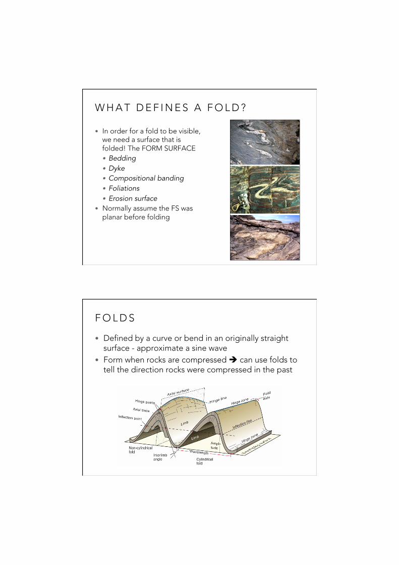
W H A T D E F I N E S A F O L D ?
• In order for a fold to be visible, we need a surface that is folded! The FORM SURFACE• Bedding • Dyke • Compositional banding • Foliations • Erosion surface
• Normally assume the FS was planar before folding
F O L D S
• Defined by a curve or bend in an originally straight surface - approximate a sine wave
• Form when rocks are compressed è can use folds to tell the direction rocks were compressed in the past
29/10/18
4
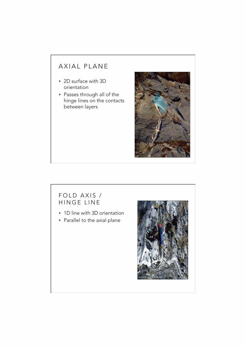
A X I A L P L A N E
• 2D surface with 3D orientation
• Passes through all of the hinge lines on the contacts between layers
F O L D A X I S / H I N G E L I N E
• 1D line with 3D orientation• Parallel to the axial plane
folk.uib.no (H. Fossen)
29/10/18
5
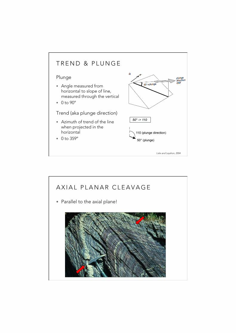
T R E N D & P L U N G E
Plunge
• Angle measured from horizontal to slope of line, measured through the vertical
• 0 to 90°
Trend (aka plunge direction)
• Azimuth of trend of the line when projected in the horizontal
• 0 to 359°
Lisle and Leyshon, 2004
A X I A L P L A N A R C L E A V A G E
• Parallel to the axial plane!

29/10/18
6
F O L D S H A P E
• How rounded or pointy is the hinge zone?
F O L D S H A P E
• Interlimb angle: the angle between the limbs!

29/10/18
7
F O L D O R I E N T A T I O N
• Two pieces of information required to define fold attitude:
• Fold axis trend and plunge
• Fold axial plane strike and dip
F O L D C L A S S I F I C A T I O N
Younging direction, aka up-direction:
• Original top or upper side of a sedimentary or volcanic bed
• Can be determined using some kinds of primary sedimentary structures, such as graded bedding and cross bedding

29/10/18
8
W H Y D O F O L D S F O R M ?
• Compression. A good assumption: the compression direction was perpendicular to the axial plane
S T R A I N
• Quantitative measure of the change in shape, size, volume, orientation, or position of any deformed feature in a rock

29/10/18
9
G E O L O G Y C A N G E T C O M P L I C A T E D
• Folds are sometimes folded again
video link: http://www.ged.rwth-aachen.de/index.php?cat=Media&subcat=Videos&page=Videos
S T E R E O N E T S
• Used to represent 3D orientation of planes and lines• Graphical calculator for analyzing 3D data

29/10/18
10
010
100
090
080
070
060
050
040
030020
110
200190 180 170
160150
140
130
120
210
300
290
280
270
260
250
240
230
220
310
350340
330
320
North
Davis et al., 2012
• Great circles from N to S – intersect at poles
• Small circles from E to W – don’t intersect
• Primitive circle – circumference
S T E R E O N E T S
• In structural geology, we always project from the lower half of the sphere
• “Lower hemisphere projection”
S T E R E O G R A P H P R O J E C T I O N
29/10/18
11
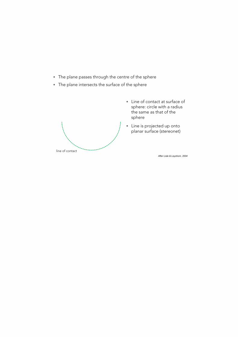
line of contact
• The plane passes through the centre of the sphere
• The plane intersects the surface of the sphere
After Lisle & Leyshorn, 2004
• Line of contact at surface of sphere: circle with a radius the same as that of the sphere
• Line is projected up onto planar surface (stereonet)
S T E R E O G R A P H P R O J E C T I O N : P L A N E S
• Consider curved line on the hemisphere as a series of points
• Project a line through each point to the zenith, intersecting the plane of projection
zenith<
plane of projection
After Lisle & Leyshorn, 2004
S T E R E O G R A P H P R O J E C T I O N : P L A N E S

29/10/18
12
• This intersection is the stereographic projection of the plane
• The result: an arc on a horizontal plane (stereonet)
After Lisle & Leyshorn, 2004
primitive circle
+
N
plane
Davis et al., 2012
Planes (2D) plot as curves (1D) on a stereonet...
S T E R E O G R A P H P R O J E C T I O N : P L A N E S
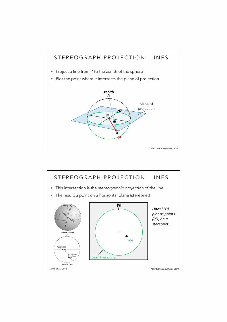
• The line passes through the centre of the sphere (E)
• The line intersects the surface of the sphere at point (P)
E
P
After Lisle & Leyshorn, 2004
S T E R E O G R A P H P R O J E C T I O N : L I N E S
• Point is projected up onto planar surface (stereonet)
29/10/18
13
• Project a line from P to the zenith of the sphere
• Plot the point where it intersects the plane of projection
After Lisle & Leyshorn, 2004
E
P
plane of projection
zenith<
S T E R E O G R A P H P R O J E C T I O N : L I N E S
• This intersection is the stereographic projection of the line
• The result: a point on a horizontal plane (stereonet)
After Lisle & Leyshorn, 2004
primitive circle
+
N
line
Davis et al., 2012
Lines(1D)plotaspoints(0D)onastereonet...
S T E R E O G R A P H P R O J E C T I O N : L I N E S
29/10/18
14
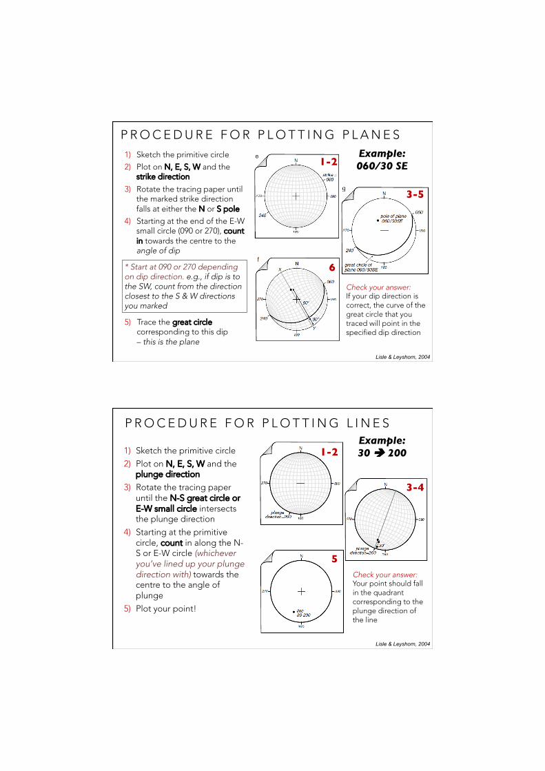
P R O C E D U R E F O R P L O T T I N G P L A N E S1) Sketch the primitive circle
2) Plot on N, E, S, W and the strike direction
3) Rotate the tracing paper until the marked strike direction falls at either the N or S pole
4) Starting at the end of the E-W small circle (090 or 270), count in towards the centre to the angle of dip
* Start at 090 or 270 depending on dip direction. e.g., if dip is to the SW, count from the direction closest to the S & W directions you marked
5) Trace the great circle corresponding to this dip – this is the plane
Lisle & Leyshorn, 2004
1-2
3-5
6
Example:060/30 SE
Check your answer: If your dip direction is correct, the curve of the great circle that you traced will point in the specified dip direction
P R O C E D U R E F O R P L O T T I N G L I N E S
1) Sketch the primitive circle
2) Plot on N, E, S, W and the plunge direction
3) Rotate the tracing paper until the N-S great circle or E-W small circle intersects the plunge direction
4) Starting at the primitive circle, count in along the N-S or E-W circle (whichever you’ve lined up your plunge direction with) towards the centre to the angle of plunge
5) Plot your point!
Lisle & Leyshorn, 2004
1-2
3-4
5
Example:30 è 200
Check your answer: Your point should fall in the quadrant corresponding to the plunge direction of the line