EPS044 and NMS044 Reference Manual - Larson Davis
59
Larson Davis SoundAdvisor Model NMS044 Reference Manual
Transcript of EPS044 and NMS044 Reference Manual - Larson Davis

Larson Davis
SoundAdvisor Model NMS044
Reference Manual

NMS044 Reference Manual i-2
CopyrightCopyright 2021, by PCB Piezotronics, Inc. This manual is copyrighted, with all rights reserved. The manual may not be copiedin whole or in part for any use without prior written consent of PCB Piezotronics, Inc.
Trademarks in this ManualAndroid and the Google Play Store are trademarks of Google, LLC in the U.S. and in other countries. iTunes Store is a trademarkof Apple, Inc. in the U.S. and in other countries. IOS is a registered trademark of Cisco Systems in the U.S. and in other coun-tries. SoundAdvisor 831C is a trademark of PCB Piezotronics, Inc.
DisclaimerThe following paragraph does not apply in any state or country where such statements are not agreeable with local law:
Even though PCB Piezotronics, Inc. has reviewed its documentation, PCB Piezotronics Inc. makes no warranty or representa-tion, either expressed or implied, with respect to this instrument and documentation, its quality, performance, merchantabil-ity, or fitness for a particular purpose. This documentation is subject to change without notice, and should not be construed asa commitment or representation by PCB Piezotronics, Inc.
This publication may contain inaccuracies or typographical errors. PCB Piezotronics, Inc. will periodically update the materialfor inclusion in new editions. Changes and improvements to the information described in this manual may be made at anytime.
SafetyIf the equipment is used in a manner not specified by Larson Davis, the protection provided by the equipment may beimpaired.
RecyclingPCB Piezotronics, Inc. is an environmentally friendly organization and encourages our customers to be environmentally con-scious. When this product reaches its end of life, please recycle the product through a local recycling center or return the prod-uct to PCB at the following address:
PCB Piezotronics, Inc.Attn: Recycling Coordinator1681 West 820 NorthProvo, Utah, USA 84601-1341
Warranty
For warranty information, refer to the Larson Davis Product Warranty page.

NMS044 Reference Manual, Rev G ii-1
Table of Contents
Module 1 System Overview - - - - - - - - - - - - - - - - - - - - - - - - - - - - - - - - - - - - - - - - - - - - - - - - - 11.1 System Contents1.2 Optional Accessories1.3 Understanding NMS044 Power Consumption
Module 2 Getting Started - - - - - - - - - - - - - - - - - - - - - - - - - - - - - - - - - - - - - - - - - - - - - - - - - - - 92.1 Completing System Assembly2.2 Establishing Service for the Gateway2.3 Connecting the Gateway to Cellular Service2.4 Reviewing 831C SLM System Properties for Use With NMS0442.5 Using SoundLink
Module 3 Installing the NMS System - - - - - - - - - - - - - - - - - - - - - - - - - - - - - - - - - - - - - - - - - 213.1 Assembling Travel Packs3.2 Assembling the EPS2116 and Preamplifier3.3 Installing the Pole and EPS21163.4 Connecting the Solar Panel3.5 Powering On the NMS044 System3.6 Calibrating the Sound Level Meter3.7 Conducting a Final Equipment Check
Module 4 Making Measurements - - - - - - - - - - - - - - - - - - - - - - - - - - - - - - - - - - - - - - - - - - - - 314.1 Configuring a Measurement Setup4.2 Downloading and Viewing Measurement Data
Appendix A Additional System Information- - - - - - - - - - - - - - - - - - - - - - - - - - - - - - - - - - - - - A-1A.1 System LED IndicationsA.2 Shipping and Storage RequirementsA.3 Understanding 831C SLM ConnectionsA.4 Updating NMS044 for Modem Low PowerA.5 Configuring the Gateway for Larson Davis Instruments
Appendix B Technical Specifications - - - - - - - - - - - - - - - - - - - - - - - - - - - - - - - - - - - - - - - - - - B-1B.1 Physical CharacteristicsB.2 Declaration of Conformity

NMS044 Reference Manual 1
Module 1 System Overview
The SoundAdvisor Model NMS044 noise monitoring system is the practicalsolution to short- or long-term, unattended sound level monitoring. Power issupplied by a 12-Volt battery, charged by a solar panel, which is positioned inan area where sunlight is most available.
In this module:1.1 System Contents .................................................................................................................1-2
1.2 Optional Accessories ...........................................................................................................1-5
1.3 Understanding NMS044 Power Consumption ...................................................................1-6
Figure 1-1 EPS044/NMS044 Features
1. Reliable and Durable The system (including the battery, charge controller, antennas, modem, and SLM) is enclosed in a durable case. The environmentally-protected, prepolarized microphone and preamplifier provide reliable acoustic measurements.
2. Portable, Easily Deployed System The system weighs as little as 50 lb (23 kg). This enables one person to deliver and set up the system in only a few minutes. The NMS044 can be deployed, before, during, or after you setup the 831C.
3. Remote Connectivity Access and control the system remotely by connecting to the gateway via a cellular network on your mobile phone or PC. Using LD Atlas (mobile) or G4 LD Utility (PC), view and download data anytime.
4. Low Power Consumption When enabled and used in conjunction with the low power cable, the modem low power mode runs basic features with exceptionally low power consumption. When a solar panel is part of the system, a minimal amount of sunlight is needed to reboot in case a power loss occurs. Using solar power, the system charges to capacity in only a few hours.
5. Continuous Sound Measurement When using Continuous Run Mode, if the
battery is ever close to depleted, the system is designed to save the current measurement data and shut down safely. When the battery is sufficiently recharged, the system powers on and the previous measurement continues.
4.
3.
1, 2
5.
1

NMS044 Reference Manual System Contents 2
1.1 System Contents
In this section, review your system contents to identify items received.
• NMS Systems: Outdoor Equipment for Environmental Noise Monitoring
• EPS Kits: Outdoor Equipment for Environmental Noise Monitoring
NMS Systems: Outdoor Equipment for Environmental Noise MonitoringNMS systems are identified here in terms of the battery type and solar panel size. Table1.3 shows which NMS systems use EPS044-SLA kits or EPS044-LFP kits for power and listssystem contents. See Figure 1-2 for an image of each item.
Figure 1-2 Images of NMS044 Systems Contents
5.1. 6a. or 6b.
3.
4a. OR
7.
4b.
2.
Table 1.3 Description of NMS044 Systems Contents
Kit#
Contents
*Kit is available as:kit # -U: EMEA modem, PSA039 with
U.S. plugkit # -E: EMEA modem, PSA039 with Int’l
plugkit # -A: APAC modem, PSA039 with
Int’l plug
NM
S044
-SLA
100*
NMS0
44-S
LA60
*
NMS0
44-L
FP10
0*
NMS0
44-L
FP60
*
NMS0
44-K
IT1-
U
NMS0
44RI
-SLA
100-
U
1. SoundAdvisor 831C Sound Level Meter (831C)with Firmware Options831C-ELA, 831C-LOG, 831C-SW
X X X X X

NMS044 Reference Manual System Contents 3
2. G4 LD Utility Software X X X X X
3. RV50X cellular gateway with GPS antenna (COM-RV50X)
X X X X X
4a. 60 W Solar Panel kit (SLP001) X X
4b. 100 W Solar Panel kit (SLP002) X X X
5. Environmental Protection for Outdoor Acoustic Equipment Kit (EPS2116)
X X X X X
6a. Preamplifier/Mic Combo: PRM2103FF & 377B02
X X X X
6b. Preamplifier/Mic Combo: PRM2103FF & 377C20
X
7. Cables & Adapters: Signal cable with LP Mode (CBL222LP) Gateway to power block cable
(CBL223)Gateway to SLM power switch cable
(CBL218)USB to micro-B cable for system setup
(CBL138)2-port USB Adapter (DVX015)120 V AC Battery Charger Adapter
(PSA039)
X X X X X
EPS044-SLA Kit See Figure 1-4 for kit contents. X X X
EPS044-LFP Kit See Figure 1-4 for kit contents. X X
Table 1.3 (Continued)Description of NMS044 Systems Contents
Kit#
Contents
*Kit is available as:kit # -U: EMEA modem, PSA039 with
U.S. plugkit # -E: EMEA modem, PSA039 with Int’l
plugkit # -A: APAC modem, PSA039 with
Int’l plug
NM
S044
-SLA
100*
NMS0
44-S
LA60
*
NMS0
44-L
FP10
0*
NMS0
44-L
FP60
*
NMS0
44-K
IT1-
U
NMS0
44RI
-SLA
100-
U

NMS044 Reference Manual System Contents 4
EPS Kits: Outdoor Equipment for Environmental Noise MonitoringTable 1.5 lists the contents of 3 outdoor environmental kits. See Figure 1-4 for images ofeach item.
Figure 1-4 Images of EPS044-SLA, EPS044-LFP, and EPS044 Kit Contents
Table 1.5 Description of EPS044-SLA, EPS044-LFP, and EPS044 Kit Contents
Contents (See Figure 1-4) EPS044-SLA EPS044-LFP EPS044
1a. 35 Ah 12 V SLA Battery (BAT020) X
1b. 45 Ah 12 V LiFePo Battery (BAT019) X
2. Telescoping pole (ACC010) X X X
3a. Solar Charge Controller for SLA (PSA038) X X
3b. Solar Charge Controller for Lithium (PSA044) X
4. 831C to power block cable (CBL224) X X X
5. Fused battery cable (CBL225-01) X X X
6. Charge control to power block cable (CBL226) X X X
7. Solar Panel to solar charger cable (CBL228) X X X
8. Durable and protective case kit (CCS051) See Table 1.6 for kit contents.
X X X
Foam spacer for SLA battery X
Kit Accessories: canvas bag, guy wire ring, pole stabilization lines and stakes
X X X
1a.
1b.
3a, 3b
7. 8.
OR
2.
4.
5.
6.
7.

NMS044 Reference Manual Optional Accessories 5
1.2 Optional Accessories
Hardware• 32 GB USB Flash Storage (831-MEM32G)
• Precision Acoustic Calibrator (CAL200)
FirmwareSound Recording Firmware (831C-SR)
The optional Sound Recording firmware upgrade enables you to make event-based andmanual sound recordings in WAV or OGG format. Recordings are stored in themeasurement data and can be shared via email.
Scheduling Firmware (831C-SCH)
Table 1.6 Description and Images of Durable and Protective Case Kit (CCS051)
Contents
1. Environmentally protective case2. Metal case plate 3. Power distribution block (underneath case plate)4. Super clamp for pole attachment
Rubber Stoppers (2) one for CBL222-08 or CBL222-20, and one for EXC cable (application depends on the chosen preamplifier; see Figure A-6 or Figure A-7)
Kit Accessories: silicone grease for cable glands, hook and loop straps, cable ties, solar ring tool
1.
2.
3.
4.
NMS044 Reference Manual Understanding NMS044 Power Consumption 6
The optional Scheduling firmware upgrade (831C-SCH) enables you to conserve systempower and data usage while conducting measurements based on a repeatable weeklyschedule with schedule blocks for the following functions:
• Meter Run, Stop, Store
• Specific Measurement Trigger Levels
• Alert Notifications
• RV50X Modem Low Power
All features of the firmware option are accomplished by using G4 LD Utility software. Formore information, contact your sales representative or see the SoundAdvisor 831CManual, Module 6, which is available on the included Larson Davis USB drive or atwww.LarsonDavis.com.
SoftwareLD Atlas App for Mobile
With an established cellular connection, you can use the LD Atlas app to communicatewith the SoundAdvisor™ 831C SLM. LD Atlas is available for Android® from the GooglePlay Store®, or for IOS® from the iTunes Store®1. To install the app: open the app store onyour mobile device, search for “LD Atlas,” and follow the prompts.
1.3 Understanding NMS044 Power Consumption
We recommend the following three ideas to make the most of your available power. Thefirst is a basic formula you can use to estimate your system’s daily power consumption.The second is to employ the modem low power feature as an effective means to decreasesystem power consumption. The third is to explore helpful resources to betterunderstand the recommendations and requirements of using a solar panel to rechargebattery power.
In this section:• Estimating Power Consumption
• Understanding the Modem Low Power Feature
• Making the Most of Your Sunlight Hours
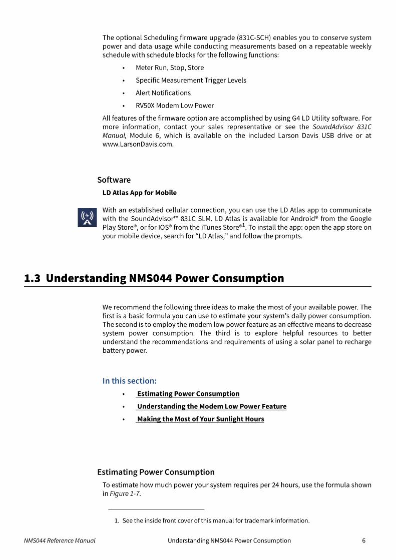
Estimating Power ConsumptionTo estimate how much power your system requires per 24 hours, use the formula shownin Figure 1-7.
1. See the inside front cover of this manual for trademark information.

NMS044 Reference Manual Understanding NMS044 Power Consumption 7
Figure 1-7 Formula for Average Watt-hours Used Per Day
To estimate the system run time in days, based on the available battery power, calculatethe following:
Figure 1-8 Formula for Days of Available Battery Power in Watt-hours
Understanding the Modem Low Power FeatureModem Low Power is an 831C system property that can be enabled or disabled tofacilitate your use. When enabled, the gateway is powered down except for theseperiods:
• when the 831C SLM powers it on to send alert notifications
• when the SLM sends a file to the cloud (SFTP, Dropbox, etc.)
• During the scheduled awake period (via 831C-SCH optional firmware add-on)
An NMS044 system purchased later than July 1, 2020 comes ready to use modem lowpower, with the power cable (CBL222LP) and SLM firmware (version 4.5 or later). Toprepare an NMS system purchased prior to July 1, 2020 for low power, see “UpdatingNMS044 for Modem Low Power” on page A-8 .
When modem low power mode is used in conjunction with the 831C Scheduling option(add-on 831C-SCH), additional power savings and regulation are possible. This optionallows you to schedule measurements as well as periods when the modem uses lowpower. For more information on the 831C Scheduling option, open G4 LD Utility, andnavigate to Help Manuals G4 LD Utility ManualModule 6.3.
P24hr = 24 (1.3 W + t (2.05 Watts))24
t = time, in hours, that the modem is powered on
Battery (Wh)(P24hr x 2)
Estimated Run Time (days) =
Battery Capacity (Wh):BAT020: 35 Ah SLA Battery = 420 WhBAT019: 45 Ah LiFPo Battery = 540 Wh
“2” = 50% safety factor to account for battery temperatureeffects and aging

NMS044 Reference Manual Understanding NMS044 Power Consumption 8
Making the Most of Your Sunlight HoursFor best results, we encourage you to take advantage of the most daylight and direct sunfor the area of deployment. The EU Science Hub’s Solar Radiation Tool, can provide anestimate of how your system performs in a particular location based on radiation datagathered for that location in the recent past.
Step 1. Visit the European Commission EU Science Hub’s Photovoltaic GIS (PVGIS)website.
Step 2. Select the Solar Radiation Tool, then select a location on the map.
Step 3. Choose the Off-Grid tab, enter the following parameters, then click VisualizeResults.
• Installed Peak PV Power (100 W or 60 W, depending on your solar panel)
• Battery Capacity (BAT021, LiFePo battery = 540 Wh; (BAT 019, SLA battery = 420 Wh)
• Discharge cutoff limit is 10%
• Consumption per day = 80 Wh (typical), but convert the result of your calculation in Figure 1-7 from watts to watt hours, and use this value.
• Enter the Slope of the solar panel, and the Azimuth. To find the azimuth, do the following:
a. Open this link for the NOAA ESRL Solar Position Calculator.b. Enter the City or the coordinates of the NMS system and click Calculate
Solar Position. c. The Solar Azimuth value – 180 = Azimuth. Enter this value in the Solar
Radiation Tool.
Step 4. Select the Performance view. The result should have no red bars (days
with no battery power). Select the Battery State view. A desirable resultshows the battery is not fully discharged at any time.
Step 5. To adjust for better results, adjust the Slope of the solar panel, or adjust thesystem location and Azimuth.
Recommended next step:• Module 2 Getting Started

NMS044 Reference Manual 9
Module 2 Getting Started
Your system ships from the factory tested and assembled, except for the final batteryconnections and final gateway configuration details. While these can be done in the fieldafter installation, we recommend completing these sections prior to remote installation.
This module assumes that you have the complete NMS044 with all components. Thesetup is similar for the EPS044, and the following sections apply to that component aswell.
In this module:2.1 Completing System Assembly ............................................................................................. 10
2.2 Establishing Service for the Gateway .................................................................................. 13
2.3 Connecting the Gateway to Cellular Service ....................................................................... 15
2.4 Reviewing 831C SLM System Properties for Use With NMS044 .......................................... 19
2.5 Using SoundLink .................................................................................................................. 20
2

NMS044 Reference Manual Completing System Assembly 10
2.1 Completing System Assembly
Figure 2-1 System Wiring Overview is shown here as reference for all system connections.
Figure 2-1 System Wiring Overview
PRM2103-FF Preamplifier and Microphone
Cellular Antennas
Sound Level Meter
Solar Charge Controller
PSA038 (for SLA battery) or PSA044 (for LiFePo battery)
COM-RV50X Cellular Gateway
GPS Antenna
ADP107 Power Distribution Block
Solar Panel
CBL222LP or CBL222
CBL223
Terminal Lug (ground to plate in case)
Battery
CBL226-02CBL225
CBL228-03
DVX015 2-port USB Hub
CBL218

NMS044 Reference Manual Completing System Assembly 11
2.1.1 Preparing the System Battery
Your NMS system ships from the factory tested and assembled, except for the finalconnection to the external battery. This section shows how to charge and connect theexternal system power.
Step 1. Install the battery in the case and connect CBL225 as shown in Figure 2-2.
Figure 2-2 Battery Installation Sequence
Step 2. (Optional) If you want to charge the system battery prior to deploying, do thefollowing:
Charging the System Battery Using AC Power (NMS044 System Only)a. Connect the solar connectors (CBL228) to the AC battery charger (part of
PSA039). The solar connectors extend from the solar charge controller; PSA039is included with the NMS044 system. Refer to Figure 2-1 System Wiring Overviewfor details.
b. Plug into an external AC power source (wall outlet).
a. Open the case and lift out the plate being careful not to pull any wires loose. Set the plate at an angle away from case.
b. If not already in place, set the battery inside the guide lines with the terminals toward the bottom of the case.
c. For the battery connection (CBL225), insert the connectors into the power distribution block—red to red and black to black—side by side in any available connector. See Figure 2-1 System Wiring Overview for reference.
d. When using EPS044 package only, leave the yellow connector disconnected.
a.
b.
c.
d.

NMS044 Reference Manual Completing System Assembly 12
c. When the battery is fully charged, disconnect the AC battery charger fromCBL228 as shown in Figure 2-2.• When the LED on the solar charge controller is blinking green, the battery
is charging.
• When the LED is solid green, the battery is nearly full or fully charged.
• When the LED is dark, ensure the battery is properly installed and the sys-tem is powered on. For more information, see “LED Indicators for SolarCharge Controllers” on page A-4.
Figure 2-3 Disconnecting the Solar Connectors (CBL228)
Step 3. (Optional) If your system included the Sealed Lead Acid battery (BAT020), insertthe included foam spacer (1 x 8 x 5-inches; 2.5 x 20 x 13-cm) to fill the spacebetween the battery and the 831C SLM.
Figure 2-4 Foam Spacer Placement for BAT020
Step 4. Place the mounting plate back into the case over the battery until fully seated.
1 2
If you need to disconnect the solar connectors, a tool is provided. 1) Insert the toolin the middle of the connection 2) pinch the locking mechanism, then pull apart.

NMS044 Reference Manual Establishing Service for the Gateway 13
2.2 Establishing Service for the Gateway
Establishing cell service for the gateway includes purchasing a SIM card with cellularservice and installing it. As indicated in this section, you can also opt to have Larson Davisinstall and activate the SIM when your system is prepared at the factory.
2.2.1 Purchasing Cellular Service
Review this section prior to purchasing cell service.
The NMS044 system requires a SIM card with a data plan. SIM cards should be configuredwith a static IP address or alternatively with a dynamic IP address used in conjunction withthe optional SoundLink service, as described in this section. Where available at anaffordable price, we recommend using a SIM card configured with a static IP address.
Step 1. When shopping for a cellular provider, verify that the service supports a public,static IP address, and that incoming connection requests are not blocked.
If this type of SIM card and service is available, move to the next step; if not, werecommend the SoundLink online hosting service. This enables you to establisha secure connection to your gateway(s) using any IP address on a virtual privatenetwork (VPN). Contact Larson Davis or your representative for moreinformation about this subscription-based service.
Step 2. Purchase a SIM card with the following features:
• A data plan sufficient to the NMS044 data usage
The amount of data your system requires is variable. For most applications, 4GB per month is sufficient. While precautions have been taken to prevent highdata use, the NMS system doesn’t regulate data use. Significant charges mayoccur if the purchased data amount is exceeded.
• No messaging/voice is needed.
Step 3. If your SIM card is configured with a static IP, request the APN (Access PointName) from your cellular provider. You will need it later in the process toconfigure your system for remote use.
TAKE NOTE If you would like Larson Davis to install the SIM and configure remote communication along with your equipment order, mail your SIM card, contact information, and APN (if applicable) to the following address:
NMS System ConfigurationLarson Davis Manufacturing Center1681 West 820 NorthProvo, Utah 84601 USA
Recommended next step:• If Larson Davis is installing the SIM card, move to 2.3 "Connecting the Gateway
to Cellular Service" on page 15. If Larson Davis is not installing the SIM card, move to 2.2.2 Installing the SIM Card.

NMS044 Reference Manual Establishing Service for the Gateway 14
2.2.2 Installing the SIM Card
With the system powered off, install the SIM card by following these steps:
Step 1. Using the provided #2 Phillips head screw driver, remove the 2 screws holdingthe gateway to the case plate, as shown in Figure 2-5.
Step 2. Make note of the unique password on the label on the bottom of the RV50X
Figure 2-5 Removing the Gateway From the Case Plate
Step 3. Using the #0 screwdriver, remove the 2 screws holding the front SIM card door,shown in Figure 2-6.
Figure 2-6 RV50X Sim Card Door Removed
Step 4. Insert the SIM card into to the top slot until it clicks.
Step 5. Replace the SIM card door and screws.
Step 6. Remount the RV50X in the case and hand-tighten the 2 case plate screws.

NMS044 Reference Manual Connecting the Gateway to Cellular Service 15
2.3 Connecting the Gateway to Cellular Service
This section shows you how to use your PC to connect the gateway to your cellular service, and verify that the service is working. The final configuration details must be provided by you. This section guides you through this process.
In this section:• 2.3.1 Connecting the Gateway via USB
Part 1: Connecting and Logging In
Part 2: Entering Cellular Network Credentials
• 2.3.2 Verifying Remote Communications via a Mobile Device
2.3.1 Connecting the Gateway via USB
Before you begin:• If you purchased the gateway from someone other than Larson Davis, or it has
been reset to factory settings, complete the process shown in “Configuring the Gateway for Larson Davis Instruments” on page A-11.
• Prepare cellular service as shown in 2.2 Establishing Service for the Gateway.
Part 1: Connecting and Logging InStep 1. Connect the RV50X gateway to your PC as shown in Figure 2-7.
Figure 2-7 Connecting to RV50X
Step 2. If the system is not already on, power on the system by pressing the powerbutton on the 831C.
TAKE NOTE The modem may take several minutes to boot. Check the status LEDs for progress. When the third LED from the left is solid green or amber, the gateway is connected to a network.
a. b.
a. From the back of the RV50X, unplug the mini-B USB cable.b. Plug a second mini-B USB cable (included) into the back of the RV50X, and
connect the other end to your PC.

NMS044 Reference Manual Connecting the Gateway to Cellular Service 16
LEARN MORE For additional information, see “Gateway LED Indications” on page A-3.
Step 3. Open a web browser on the connected PC, and enter “http://192.168.14.31:9191” into the address bar. This opens ACEmanager, thegateway configuration console.
Step 4. If this is your first time logging in, log in as “user” with the password“LD_NMSystem16.”
Figure 2-8 User Login
TAKE NOTE If the login is not working, it’s possible that the gateway has not been configured for use with Larson Davis instruments. If this is the case, refer to section “Configuring the Gateway for Larson Davis Instruments” on page A-11.
Step 5. Change the password as shown in steps 5a–5e.
Changing Your Passworda. Navigate to the Admin menu, as shown in Figure 2-9.b. If this is your first time logging in, enter “user” with the password
“LD_NMSystem16”. Otherwise, log in with the user name and passwordpreviously set for this system. TAKE NOTE If you need to reset the gateway to factory settings at some future time. Examine the label on the bottom of the modem for the factory password.
Figure 2-9 Admin Tab
c. On the Change Password sidetab, enter a unique password in New Password,and again in Retype Password.
d. Record your password. If you forget it you will need to reset the gateway tofactory settings and reconfigure.

NMS044 Reference Manual Connecting the Gateway to Cellular Service 17
e. Click Change Password, then click Apply in the top right.
Part 2: Entering Cellular Network Credentials
Step 1. Select the WAN/Cellular menu, then choose the Cellular SIM Slot 1Configuration sidetab as shown in Figure 2-10.
Figure 2-10 WAN/Cellular tab
Step 2. Expand the Network Credentials menu, and enter the APN provided by yourcellular provider in the User Entered APN field.
Step 3. Click Apply in the top right, then reboot the gateway. It may take up to 1 minuteto reboot.
Step 4. Log in using the new password.
Step 5. Navigate to Status Home. If the SIM card is set up correctly, the NetworkState field displays “Network Ready”.
Step 6. If your system relies on a static IP address, verify that the Active WAN IPAddress matches the static address given to you by your cellular provider, asshown in Figure 2-11. If you’re using SoundLink IP Hosting service, the ActiveWAN IP should match your SoundLink IP address.
Figure 2-11 Status tab
Step 7. Set up a Trusted IP (Friends) list to promote system security. When this isenabled, the IP addresses on this list can connect to the gateway. This preventsIP addresses not on the list from accessing your system and reduces power
2.

NMS044 Reference Manual Connecting the Gateway to Cellular Service 18
consumption resulting from unauthorized users repeatedly attempting toconnect.
Setting Up the Trusted IP Lista. Select the Security menu, then choose the Trusted IP - Inbound (Friends)
sidetab.b. Under Inbound Trusted IP List (Inbound Trusted IP Range) enter the public IP
address given to you by your cellular provider. Enter any other IP address (oraddress ranges) that should have remote access to the gateway. Contact yourlocal IT professional if you need more information.
c. Set Inbound Trusted IP (Friends List) Mode to Enable.
Step 8. Click Apply, and Log out of ACEmanager.
Step 9. Disconnect the USB cable from the PC and modem. Return the original mini-BUSB connector to the modem.
Step 10. Press the 831C on/off button to reboot the system.
2.3.2 Verifying Remote Communications via a Mobile Device
Establishing a connection to the SoundAdvisor™ 831C SLM prior to deployment verifiesthat the service is working properly. Larson Davis provides 2 useful utilities for conductingremote measurements:
• The G4 LD Utility software provides remote operation and control during measurements, with display, manipulation, and reports for the resulting measurement data.
• The LD Atlas app provides the same features for a mobile device.
This section demonstrates establishing a remote connection using a mobile device. Youcan also establish this same connection to the 831C SLM using G4 LD Utility on your PC.
Step 1. Download the LD Atlas app from the Google Play Store™(for Android®) or from the iTunes Store™ (for IOS®)1.
Step 2. Open the app, and tap the plus icon in-line with Metersin the top left. This opens the Add New TCP/IP Meter screen.
Step 3. Enter a Name for the NMS system.
Step 4. Enter the IP Address/Host Name from your cellular provider. If you are usingthe SoundLink IP Hosting service, enter the SoundLink IP address from yourSoundLink Plan Details email.
1. Trademark and registered trademark information is located on the inside front cover of this manual.

NMS044 Reference Manual Reviewing 831C SLM System Properties for Use With NMS044 19
Step 5. Leave the Password and Port fields blank unless instructed otherwise by yourIT professional.
Figure 2-12 Step 6. Tap the blue plus button to connect. The
Add Meter screen closes. If the NMSsystem and your mobile device havecellular service, the serial number of the831C displays in the Meters list with ablue meter icon. The meter is connectedon your device.
TAKE NOTE The connection may take up to 1 minute to display.
Step 7. Tap on the meter serial number to open the meter screen. From here, you canoperate the 831C from the app.
2.4 Reviewing 831C SLM System Properties for Use With NMS044
If Larson Davis prepared your NMS044, the following 831C system properties, appropriatefor use with the NMS044, are pre-selected for you.
If you are configuring your own system, we recommend these system properties.
• On the System Properties Power page, choose Alkaline from the Internal Battery drop-down menu, and choose Off from the Charge drop-down menu.
• Set Auto-Off Time to Never.
• On the System Properties Preferences page, Auto-Store is set to Store. This allows measurement data to be automatically saved at the end of each measurement.
• GPS Mode is set to On.
Recommended next step:• If you’re using SoundLink service, see 2.5 Using SoundLink. Otherwise, move
to Module 3 Installing the NMS System.
+ Meters

NMS044 Reference Manual Using SoundLink 20
2.5 Using SoundLink
SoundLink is an IP hosting service that provides secure communication with your remotenoise monitoring systems using a dynamic IP address. This service from Larson Davissimplifies remote communication with your NMS system. It is an alternative to using apublic, static IP address from your cellular provider, or a viable solution if one is notavailable. It works because G4 recognizes SoundLink as a static IP address even though thecell service connects via a dynamic IP address.
LEARN MORE For more information, contact your Larson Davis representative or view the SoundLink manual at LarsonDavis.com.
Larson Davis provides complete gateway configuration plus SoundLink configurationservice for new or previously deployed gateways. For previously deployed units without apublic, static IP, the SoundLink configuration service requires that you ship the gateway toLarson Davis.
For new systems, if you prefer to configure the gateway for SoundLink service yourself,complete the following steps:
Step 1. Complete the initial gateway setup as shown section 2.3 Connecting theGateway to Cellular Service.
Step 2. Complete the SLM setup as shown in section 2.4 Reviewing 831C SLM SystemProperties for Use With NMS044.
Step 3. Complete SoundLink setup as shown in the SoundLink manual. The manual isattached to your SoundLink Plan Details email from Larson Davis. When thisprocess is complete, your new NMS system is ready for deployment.
Recommended next step:• Module 3 Installing the NMS System

NMS044 Reference Manual 21
Module 3 Installing the NMS System
This module demonstrates setting up the NMS044 in the field. We recommend that youreview this module prior to delivering the system on site.
LEARN MORE If you want to access this information in video format, right-click NMS044 Assembly and Deployment video and open the video in a new browser tab.
In this module:3.1 Assembling Travel Packs ...................................................................................................... 22
3.2 Assembling the EPS2116 and Preamplifier ......................................................................... 22
3.3 Installing the Pole and EPS2116 .......................................................................................... 24
3.4 Connecting the Solar Panel ................................................................................................. 25
3.5 Powering On the NMS044 System ....................................................................................... 26
3.6 Calibrating the Sound Level Meter ...................................................................................... 27
3.7 Conducting a Final Equipment Check ................................................................................. 28
Figure 3-1 Fully-deployed NMS044 system
3

NMS044 Reference Manual Assembling Travel Packs 22
3.1 Assembling Travel Packs
Assemble all components in the recommended 3 travel packs. See Figure 3-2.
Figure 3-2 NMS044 Deployment Travel Packs
3.2 Assembling the EPS2116 and Preamplifier
Step 1. Remove rubber cap from top of preamplifier.
Step 2. Place microphone on preamplifier, then gently screw together until hand tight.Set aside. (You can store these connected, so you don’t need to repeat this stepwith every deployment.)
Figure 3-3 Connecting Microphone and Preamplifier
Solar Panel in case
EPS2116, telescoping pole, preamplifier, and microphone, guy wire ring, and stakes
NMS044 case with battery, Model 831C SLM, RV50X gateway, charge controller antennas, and all connections

NMS044 Reference Manual Assembling the EPS2116 and Preamplifier 23
Step 3. Hold the EPS2116 windscreen and birdspike together, and unscrew the topsection from the bottom section.
Step 4. Reassemble the top and base together. The EPS2116 should now appear in twopieces, as shown in Figure 3-4.
Figure 3-4 EPS2116 Separated
Step 5. Complete the steps shown in Figure 3-5.
Figure 3-5 EPS2116 Threading
Step 6. Replace the birdspike and windscreen on top of the EPS2116.
CAUTION If you need to remove the windscreen, do not pull it off the birdspike with an upward motion. First, unscrew the birdspike by twisting its top and then pull the windscreen down over the bottom of the unscrewed birdspike.
LEARN MORE To learn more about the assembly of the EPS2116 refer to the EPS2116 Reference Manual.
Top
Base
Birdspike
Windscreen
a. b. c.a. Thread the CBL222-08 cable
upward through the base and top. b. Align the red dot on the bottom of
the preamplifier to the red dot on the top of CBL222-08, and gently push together until mounted.
c. Gently ease the cable back down until the microphone is seated at the top of the EPS2116.

NMS044 Reference Manual Installing the Pole and EPS2116 24
3.3 Installing the Pole and EPS2116
Step 1. Remove the protective caps from the top and bottom of the telescoping pole.
Step 2. Put the guy wire ring on the top of the pole, and position the signal cablebetween two mount points on the guy wire ring.
Step 3. Place the EPS2116 on the top of the pole; and hold it still, while twisting thepole to screw the two pieces together as shown in Figure 3-6.
Figure 3-6 EPS2116 to Telescoping Pole
Step 4. Adjust the pole clamp screw, so the clamp is open to a 90° angle, as shown inFigure 3-7.
Figure 3-7 Pole Clamp is Ready to Receive the Pole

NMS044 Reference Manual Connecting the Solar Panel 25
Step 5. Place the pole in the clamp on the system case, and twist clamp screwclockwise to secure the pole.
Figure 3-8 Telescoping Pole With Super Clamp
Step 6. To extend sections of the pole, loosen the telescoping pole binders, extend thepole, and tighten the binders.
Step 7. Use the hook and loop cable straps (already on the cable) to secure the signalcable to the pole.
Step 8. Place the guy wire ring over the screw, which is on the top of the pole.
Step 9. Steady the pole by tying the 3 guy wires to the guy wire ring on one end and theground stakes on the other.
Step 10. Press the stakes into the ground, so that the guy wires are taught.
3.4 Connecting the Solar Panel
Step 1. Unlatch the solar panel to open.
Step 2. Loosen the thumb screws to extend legs. Match the angle of the legs on bothsides.
Step 3. Connect the CBL228 solar connectors to the solar panel connectors.

NMS044 Reference Manual Powering On the NMS044 System 26
Step 4. Place the solar panel in a secure, unobstructed, flat location facing toward thesky with optimal sunlight.
Figure 3-9 Solar Connection
3.5 Powering On the NMS044 System
Step 1. Press the power button on the 831C to power the whole system on.
Figure 3-10 NMS044 Power
We recommend placing stakes or a heavyweight, like sandbags, on the solar panellegs tokeep it in place. For details on disconnectingsolar connectors, see Figure 2-3 on page 12.
Power

NMS044 Reference Manual Calibrating the Sound Level Meter 27
3.6 Calibrating the Sound Level Meter
Refer to your calibrator and microphone-preamplifier product manuals for specificrequirements in performing the acoustic calibration.
TAKE NOTE For best results, use Larson Davis Precision Acoustic Calibrators and Larson Davis Microphone-Preamplifiers.
TAKE NOTE We recommended that you calibrate the 831C after deploying the system.
Step 1. Holding the windscreen and birdspike together, unscrew the assemblies untilthey come apart.
Step 2. Place the calibrator gently over the microphone to avoid sudden large pressurechanges to the diaphragm.
Step 3. On the sound level meter, navigate to Tools 3 Calibrate.
Step 4. Select the calibrator from the Select Calibrator drop-down menu.
Step 5. If the calibrator settings need to be modified, click Edit Settings, make anynecessary changes, then verify that the settings correspond to those describedin the calibrator’s manual.
Step 6. Press the power button on the calibrator.
Step 7. On the meter, select Do Calibration.
Figure 3-11 Acoustic Calibration

NMS044 Reference Manual Conducting a Final Equipment Check 28
Step 8. After a few seconds, a message appears indicating the measured difference anda prompt to save the results. Click Yes to save the calibration, or click No toreject it.
Figure 3-12 Measured Calibration Difference
Step 9. Carefully remove the calibrator from the microphone.
Step 10. Select the Calibration History tab to view the acoustic calibration or thecalibration check summaries.
Step 11. When the calibration process is complete, assemble windscreen and birdspikeback on the microphone.
3.7 Conducting a Final Equipment Check
We recommend that you complete these steps prior to leaving the system.
3.7.1 Checking System Status Indicators
Figure 3-13 explains the system status indicators.
Figure 3-13 NMS System Status LEDs
1. 2.
1. Verify that the system battery is charged orcharging. The system battery is fully charged when the solarcharge controller LED is solid green. A blinking greenindicates it is currently charging.
LEARN MORE All system battery status indications are shown in Table A.5 Genasun Solar Charge Controller LED Indication Patterns.
2. Check the gateway status. The RV50X gateway has 4 LED status indicators on theside of the unit. From left to right, indicators informyou of the gateway’s Network, Signal, Activity, andPower.

NMS044 Reference Manual Conducting a Final Equipment Check 29
Figure 3-14 Gateway Status Indicators
3.7.2 Verifying Cellular Service by Using the LD Atlas App
Connecting to the 831C while in the field using the LD Atlas app helps you determine if theservice is working properly. You can find a process for doing this in 2.3.2 "Verifying RemoteCommunications via a Mobile Device" on page 18.
3.7.3 Acquiring the Gateway GPS Signal
When you deploy and power on the system, you can use LD Atlas or the G4 Live View, GPSPage to verify the gateway is streaming the GPS location. When configured correctly andwhen the gateway is positioned in the path of at least 3 satellite signals, the unit’s GPSlocation displays on the GPS Page; 4 or more satellite signals activate the local time asshown in Figure 3-15.
Figure 3-15 GPS Page, G4 Live View
Troubleshooting the GPS SignalActive GPS display is dependent on these settings:
• 831C GPS Mode: Available on the 831C Tools System Properties Other. For more information, see 2.4 "Reviewing 831C SLM System Properties for Use With NMS044" on page 19
• Gateway Location/Streaming Settings: For details, see Figure A-17 and Figure A-18 in Appendix A.
All gateway status indicators areshown in “LED Indicators for RV50XCellular Gateway” on page A-3.

NMS044 Reference Manual Conducting a Final Equipment Check 30
3.7.4 Securing the Case With a Lock
The NMS044 case latches tight, and a lock can be used to secure it. You could also chainthe system to a fixed object to deter theft.
Recommended next step:• Module 4 Making Measurements

NMS044 Reference Manual Configuring a Measurement Setup 31
Module 4 Making Measurements
Configuring a measurement setup file for the SoundAdvisor™ 831C sound level meter canbe done prior, during, or after deployment. You can change settings, check themeasurement, or download data at any time.
In addition to this manual, the G4 LD Utility Manual and the SoundAdvisor 831C Manualcontain a great deal of information about making measurements using Larson Davisinstruments. This module refers you to each of these manuals as needed.
Before you begin:• Assemble and activate your NMS system as shown in Module 2 Getting Started
and Module 3 Installing the NMS System.
In this module:4.1 Configuring a Measurement Setup ...................................................................................4-31
4.1.1 Reviewing and Saving a New Setup File4.1.2 Configuring the Meter to Send Alert Notifications4.1.3 Additional 831C Features and Settings
4.2 Downloading and Viewing Measurement Data ................................................................4-354.2.1 Listening to Audio Files
4.1 Configuring a Measurement Setup
For convenience, a default setup file for the NMS044 is included on the 831C. The file isnamed after the system. It contains metrics that are commonly used when measuringoutdoor noise, such as:
• Measurement History with 1-hour measurement intervals
• Time History with 1-second updates to view noise as a function of time.
• Daily results
• Event Triggers, configured to send email alert notifications (when email is set up on the 831C).
Additionally, you may want to customize the SLM meter settings for your measurement.Complete the following processes to review and customize the SLM settings for yourmeasurement.
4

NMS044 Reference Manual Configuring a Measurement Setup 32
In this section:• 4.1.1 Reviewing and Saving a New Setup File
• 4.1.2 Configuring the Meter to Send Alert Notifications
• 4.1.3 Additional 831C Features and Settings
4.1.1 Reviewing and Saving a New Setup File
If you need to customize the provided NMS044 setup file, be sure to save it with a customname so you can reuse it another time or transfer it to a PC to be transfered to othermeters.
Step 1. Using G4, navigate to the Setup Manager.
Step 2. On the right side (meter side), select the setup file NMS044.
Step 3. Click the tab arrow in the bottom right or left to access and review pages ofthe Setup file as shown in Figure 4-1, Figure 4-2, Figure 4-4:
Figure 4-1 NMS044 Setup File: Control Page ,
In addition to the meter run modes shown on the Control page, the 831C SLM offers aScheduling firmware upgrade (831C-SCH) for use with G4 LD Utility. This upgrade enablesyou to operate a meter based on a repeatable weekly schedule with schedule blocks forthe following meter functions:
• Meter Run, Stop, Store
• Specific Measurement Trigger Levels
• Alert Notifications
• Gateway (Modem) Low Power
2.
1.1. Continuous Run Mode is often used for outdoor noise
measurements. In this mode the meter begins measuring when the meter is powered on and continues to run until you stop it, or until the meter is powered off. If the system loses power and then is recharged sufficiently, it powers on and automatically resumes measuring.
2. The Daily Auto Store feature is set to store a data file once every 24 hours. As a result, the data file will contain 24 measurement intervals, with each one containing 1 hour of data.
3. The PRM2103 preamplifier is set to do a daily automatic calibration check (Cal. Check) at 02:30:00 to ensure that the measurements are accurate.
4. Measurement History is only available with the 831C-ELA or 831C-MSR firmware option purchased and installed on the 831C SLM. For more information, contact Larson Davis as shown on the back cover of this manual.
4.

NMS044 Reference Manual Configuring a Measurement Setup 33
LEARN MORE For more information about using this feature, in G4 go to Help Manuals G4 LD Utility 6.3 Using Scheduling Firmware.
Figure 4-2 NMS044 Setup File: Time History Tab
The following settings, as shown on the Event Triggers, Event History, and Sound pages,create event-based sound recordings that are stored in the measurement data and can beshared via email.
Figure 4-3 NMS044 Settings: Triggers, Events, and Sound
2.
1. Using Time History with a 1-secondPeriod creates one record each second inthe measurement data table.
2. Each record contains the metricsselected in the Time History Optionssection. The NMS044 setup file currentlycontains the default metrics shown here.
1.
1. 2. 3.1. The Event Trigger Method is set to Level.
2. When the measured sound level exceeds the set Trigger Level, an event is triggered and a sound recording begins. By default, the Trigger Sources are set to SPL 1 and Peak 1. The Trigger Levels for these 2
sources can only be edited from the Exceedance Triggers page (press left arrow icon twice ). Alternatively, you may select other Triggers Sources from the drop-down menu, and edit the associated Trigger Levels directly from the Event Triggers page.
3. The recording saves 7 seconds of sound as indicated in the Snapshot Time field. With the checkbox in-line with Compression selected, the sound file is saved using OGG compression. When this is the case, any email alert notifications sent as a result of the exceedance include the sound recording as an attachment.

NMS044 Reference Manual Configuring a Measurement Setup 34
LEARN MORE For more information about level and dynamic triggering, see SoundAdvisor 831C Manual 17.5 Understanding Level and Dynamic Triggering.
For more information on configuring alert notifications, see G4 LD Utility Manual 6.1.5 Understanding Alert Notifications
Step 4. When you’re finished reviewing or editing the NMS044 Setup file, click themenu icon , and choose Setup Manager.
Step 5. If you made changes to the NMS044 setup file, do the following:
Saving a New Setup Filea. Right-click on the name of the setup in the list. This opens the Menu.b. Choose Save As, enter a custom setup name, and click OK.
Figure 4-4 Setup Menu
Step 6. Finally, in the Setup Manager list, highlight the setup you want to use for theupcoming measurement, right-click to open the Menu, and select Set to Active.
4.1.2 Configuring the Meter to Send Alert Notifications
The 831C SLM can be set up to send email and text alert notifications for a variety of systemevents, as well as measurement and sound events. When an event (setting change,exceedance trigger, sound event, etc.) occurs and the meter has an active networkconnection, the meter sends the alert notification after the event has concluded.
Using G4 version 4.5 or newer, alert notifications for system-, event-, and measurementhistory-triggered events are set up through a user account on the meter. To configure this,launch G4, and go to Help Manuals G4 LD Utility ManualModule 6.1 GettingStarted With 831C Accounts in G4. Additionally, you can apply the same process shownthere (with slight adaptation for mobile) when using the LD Atlas app.

NMS044 Reference Manual Downloading and Viewing Measurement Data 35
4.1.3 Additional 831C Features and Settings
The SoundAdvisor 831C provides additional settings and features that may be helpful foryour measurement, including the optional Scheduling firmware add-on for 831C (831C-SCH).
For more information on using these features, in G4 go to Help Manuals G4LD UtilityManualModule 6 G4 Features for SoundAdvisor 831C.
4.2 Downloading and Viewing Measurement Data
For more information about downloading and viewing measurement data, review thefollowing modules. In G4 go to Help Manuals G4 LD Utility Manual:
• 2.5 Downloading Measurement Data Files
• 2.6 Viewing Downloaded Data in G4
• 2.7 Exporting Data to a Spreadsheet
4.2.1 Listening to Audio Files
For more information about listening to your recorded audio files, refer to the followingmodules. In G4, go to Help Manuals G4 LD Utility Manual:
• 3.3.2 Audio Playback for SLMs
• 3.3.3 Listening to Streaming Audio for SLMs

NMS044 Reference Manual System LED Indications A-1
Appendix A Additional System Information
In this module:A.1 System LED Indications .......................................................................................................A-1
A.1.1 LED Indicators for SoundAdvisor™ Model 831C SLMA.1.2 LED Indicators for RV50X Cellular GatewayA.1.3 LED Indicators for Solar Charge Controllers
A.2 Shipping and Storage Requirements .................................................................................A-5A.2.1 Shipping the SystemA.2.2 Preparing the System for Long Term StorageA.2.3 Removing Cables From the Case
A.3 Understanding 831C SLM Connections ..............................................................................A-7
A.4 Updating NMS044 for Modem Low Power .........................................................................A-8A.4.1 Installing the Modem LP CableA.4.2 Upgrading 831C SLM FirmwareA.4.3 Enabling Modem Low Power
A.5 Configuring the Gateway for Larson Davis Instruments .................................................A-11A.5.1 Logging In to ACEmanagerA.5.2 Configuring LD Settings Utilizing the Template FileA.5.3 Configuring LD Settings Without the Template File
A.1 System LED Indications
This section is a reference for LED indicators on the 831C, the cellular gateway, and thesolar charge controller.
In this section:• A.1.1 LED Indicators for SoundAdvisor™ Model 831C SLM
• A.1.2 LED Indicators for RV50X Cellular Gateway
• A.1.3 LED Indicators for Solar Charge Controllers
A.1.1 LED Indicators for SoundAdvisor™ Model 831C SLM
The SoundAdvisor™ 831C has a multi-color back-lighted keypad, which provides thefollowing colored indications for power and measurement statuses.
A

NMS044 Reference Manual System LED Indications A-2
System Power IndicatorsThe system power status is indicated by the green LED behind the SLM power button 0.
Measurement Status IndicatorsSLM measurement status is indicated by the LEDs behind the Stop button 7 and thePlay/Pause button 9 as shown in Table A.2.
Table A.1 Power Status LED Indicator
Status 0 Green LED
System is powering up or shutting down
FAST, SHORT GREEN BLINK
Table A.2 Measurement Status LED Indicators
Measurement State Red LED 7 Green LED 9
Stopped with Reset
LONG, QUICK RED BLINK OFF
Stopped LONG THEN SHORT RED BLINKOFF
Paused SHORT RED BLINK SHORT GREEN BLINK
RunningOFF
LONG THEN SHORT GREEN BLINK
Waiting for valid data to begin
running
SHORT DELAYED BLINK OFF

NMS044 Reference Manual System LED Indications A-3
A.1.2 LED Indicators for RV50X Cellular Gateway
When installed and running, the state of the gateway is indicated by the 4 LEDs on the sideand bottom of the device. Individual lighted LEDs and combination lighted LED indicationsare listed in Table A.3:
Table A.3 Gateway LED Indications
LED Color/Pattern Description
Power Off No power or input voltage > 36 Vdc or < 7 Vdc
Solid Green Power is present
Green with Amber Flash Power is present and the gateway has a GPS fix
Solid Red Standby mode
Flashing Green When you press the reset button, flashing green indicates when to release the reset button to reboot the gateway.
Flashing Red When you press the reset button, flashing red indicates when to release the reset button to reset the gateway to the factory default
settings.
Signal Solid Green Good signal (equivalent to 4-5 bars)
Solid Amber Fair signal (equivalent to 2-3 bars)
Flashing Amber Poor signal (equivalent to 1 bar)If possible, move the gateway to a location with a better signal.
Flashing Red Inadequate (equivalent to 0 bars)If possible, move the gateway to a location with a better signal
Network Solid Green Connected to an LTE network
Solid Amber Connected to a 3G or 2G network
Flashing Green Connecting to a network
Flashing Red No network available
Flashing Red/Amber Network Operator Switching is enabled, but the gateway is unable to locate the required firmware. For more information, contact Sierra
Wireless®.
Activity Flashing Green Traffic is being transmitted or received over the WAN interface.
Flashing Red Traffic is being transmitted or received over the serial port. This behavior only appears if the RV50X is configured to display it. For
more information, contact Sierra Wireless®.
Flashing Amber Traffic is being transmitted or received over both the WAN interface and the serial port. This behavior only appears if the RV50X is configured to display it. For more information, contact Sierra
Wireless®.
ALL Green LED chase Radio module reconfiguration/firmware update or Network Operator Switching is in progress.
Amber LED chase ALEOS software update is in progress.

NMS044 Reference Manual System LED Indications A-4
A.1.3 LED Indicators for Solar Charge Controllers
The NMS044 solar charge controller has 1 multi-color LED which indicates unit status asshown in this section. The Genasun Lead Acid solar charge controller (Figure A-4) is oneexample; your model may differ slightly.
Figure A-4 Example: Genasun Solar Charge Controller LEARN MORE For LED indication details, see Table A.5.
.
Table A.5 Genasun Solar Charge Controller LED Indication Patterns
LED Status Indications:
Standby: The battery is connected properly andready to charge when solar panel power isavailable.
2 SEC BETWEEN GREEN BLINKS
Charging (low current, less than -3.7A)
FAST, SHORT GREEN BLINKS
Charging (high current, more than -3.7A)
LONGER, SLOWER GREEN BLINKS
Charging (at current limit, 10.5A)
LONG THEN SHORT GREEN BLINKS
LED Error Indications:
Overheat The controller’s internal temperatureis too high.
SETS OF 2 RED BLINKS
Overload This could be caused by changing thesolar panel connections while the chargecontroller is powered.
SETS OF 3 RED BLINKS
Battery Voltage Too Low The controller cannotbegin charging due to low battery voltage. If thenominal battery voltage is correct (12V), chargethe battery by some other means before use.
SETS OF 4 RED BLINKS
Battery Voltage Too High If the battery voltageis correct (12V), check the functioning of otherchargers that may be connected to the system.
SETS OF 5 RED BLINKS

NMS044 Reference Manual Shipping and Storage Requirements A-5
A.2 Shipping and Storage Requirements
The box and packing foam your system arrived with is designed to be reused. Werecommend that you retain the packaging for future shipments.
A.2.1 Shipping the System
If you need to ship your system, be aware that the LiFePo Battery (BAT019) is consideredClass 9 Hazardous Material. The shipping vendor and you are required by law to followspecific protocol when shipping. One requirement is that a company and/or individualmust be 49 CFR and IATA certified to ship a lithium battery with over 100 Watt-hourcapacity. Recertification is required every 2 years
Prior to shipping the system, always disconnect the battery from the power blockterminal. The battery can be shipped in the case when you affix appropriate shippinglabels on the outside of the box.
CAUTION Do not transport with lid open. Only those with appropriate certifica-tion may ship batteries.
LEARN MORE Licensing can be obtained through a training course, such as the Lion Technology online training course - code #HMT 254 “Shipping Lithium Batteries”.
Table A.5 (Cont) Genasun Solar Charge Controller LED Indication Patterns
...LED Status Indications
Battery Charged The battery is in theabsorption or float charging stage.
SOLID GREEN LED
...LED Error Indications
Panel Voltage Too High Only 12V nominalsolar panels may be used with thiscontroller.
SETS OF 6 RED BLINKS
Internal Error Contact your dealer
2 LONG BLINKS, THEN ANY NUMBER OFSHORT BLINKS

NMS044 Reference Manual Shipping and Storage Requirements A-6
A.2.2 Preparing the System for Long Term Storage
If you plan to store the system for more than one week, unplug and remove the batteryfrom the case.
A.2.3 Removing Cables From the Case
If the cables need to be removed from the case, follow these steps.
Step 1. Remove the CBL228-03 from the charge controller by unscrewing the terminalsand gently pulling the cable out. Remove the CBL222-08 from the top of the831C by pressing the release button and pulling out.
Step 2. Unscrew the gasket by turning counterclockwise.
Step 3. Using your hands on either side of the case wall, gently push the rubber stopperout. The cable can be removed through the slit in the stopper.
Step 4. If needed, follow the steps in reverse order to reinstall the cables in the case.

NMS044 Reference Manual Understanding 831C SLM Connections A-7
A.3 Understanding 831C SLM Connections
The 831C SLM ships assembled with all required connections in place. This section showsthe SLM connections from Figure 2-1 on page 10 in greater detail.
There are 2 preamplifier options for the SoundAdvisor™ 831C. The PRM2103 (see Figure A-6) is used for outdoor measurement, while the PRM831 (see Figure A-7) is most often usedfor indoor measurements.
Figure A-6 Wiring Diagram for PRM2103 in the Case
Figure A-7 Wiring Diagram for PRM831 in the Case
1/4” Ground Lug
Case wall
10-pin connector
PRM2103
Anderson connector to power block
5-pin connectorSoundAdvisor Model 831C
18-pin connector to I/O connector
CBL222LP-08
1.1. If a gateway is included in your system, the CBL222LP (or CBL222) yellow On/Off trigger for
gateway power connects to the CBL223 (yellow connector) as shown in Figure 2-1 on page 10.
Case wall
5-pin connector
PRM831
5-pin connector
SoundAdvisor Model 831C
Anderson connector to power block
EXCXX cableCBL224-08
18-pin connector to I/O connector1.
1. When a gateway is included in the system, the yellow on/off trigger connects to the CBL223 (yellow connector).

NMS044 Reference Manual Updating NMS044 for Modem Low Power A-8
A.4 Updating NMS044 for Modem Low Power
When enabled for modem low power, the gateway is powered down except when the 831CSLM powers it on to send alert notifications. If this pattern of use is consistent with yourrequirements, modem low power can extend the system power supply.
This feature requires the CBL222LP gateway power cable from Larson Davis, and 831C SLMfirmware version 4.5 or later, as explained in the following sections.
Before you begin:• Check the cable tag (label) near the preamp end of your 831C. If the cable is
“CBL222LP-XX,” the system is equipped to use this feature; jump to A.4.3 Enabling Modem Low Power. If the cable is “CBL222-XX,” complete each section below in the order it’s presented to upgrade your system.
In this section:• A.4.1 Installing the Modem LP Cable
• A.4.3 Enabling Modem Low Power
A.4.1 Installing the Modem LP Cable
Step 1. Contact your Larson Davis representative (or Larson Davis, as shown on theback cover of this manual) to order the modem low power cable (CBL222LP).
Step 2. Open the system case and replace CBL222 with CBL222LP. For reference, seeFigure 2-1 on page 10.
A.4.2 Upgrading 831C SLM Firmware
If you purchased your NMS system some time ago, Larson Davis periodically releasesfirmware upgrades with significant security and feature benefits, such as modem lowpower.
To take advantage of these benefits, install the latest version of G4 LD Utility, connect your831C to your PC, and upgrade your SLM firmware, as shown in the SoundAdvisor 831CManual.
To locate and install the latest version of G4, navigate in a browser towww.LarsonDavis.com/G4

NMS044 Reference Manual Updating NMS044 for Modem Low Power A-9
A.4.3 Enabling Modem Low Power
When enabled for modem low power, the gateway is powered down except for thefollowing periods:
• when the 831C SLM powers it on to send alert notifications
• when the SLM sends a file to the cloud (SFTP, Dropbox, etc.)
• During the scheduled awake period (System Properties Other page)
You can complete this process by using G4 LD Utility on a PC or the LD Atlas app for mobile.If the system is deployed and you are using LD Atlas, you will need cellular service toconnect.
Before you begin:• Complete section A.4.1 Installing the Modem LP Cable and A.4.2 Upgrading
831C SLM Firmware.
Step 1. Launch G4 LD Utility on your PC.
Step 2. Click on the name of your connected meter in the Meters Panel. This opens themeter window on the left.
Step 3. Choose Live View Tools System Properties.
Step 4. On the System Properties page, select the Menu icon , then select Other.
Figure A-8 System PropertiesOtherStep 5. The gateway is connected by using the
SLM Logic Out via the AUX port. Fromthe Logic Out drop-down menu, selectModem.
Step 6. In the Wake Time field, enter the timeof day the gateway will power on. WakeTime should be local time for the NMSsystem.
Step 7. In the Duration field, select the lengthof time after the Wake Time that thegateway will be active. The Wake Timeplus the Duration defines a specificperiod of each day, during which thenoise monitor can be remotelyaccessed.
Step 8. If you plan to enable alert notifications, select a time from the Alert Timeoutdrop-down menu. This is the amount of time the modem remains on aftersending an alert notification. This includes time to respond to an alert, if

NMS044 Reference Manual Updating NMS044 for Modem Low Power A-10
needed. If an alert notification is sent directly following a measurement, theAlert Timeout period is in addition to the Duration.
LEARN MORE For more information about setting alert notifications through your 831C account, open the G4 LD Utility Manual, Module 6.1. To do this in G4, go to Help Manuals G4 LD Utility Manual.
Step 9. Finally, select the checkbox in-line with Enable and select Close to save thechanges. Your system is configured to use modem low power. See Table A.9 forexamples of typical power consumption.
Table A.9 Example: Low Power Mode vs Standard Power
Power Mode Configuration Continuous Run
Time
Standard System continuously running, gathering data, gateway idle 23 hours/day, streaming 1
hour/day2.5 days
Low Power System continuously running, gathering data; gateway in Low Power Mode 23 hours/
day, streaming 1 hour /day6.25 days
This example was calculated using the SLA battery (BAT019)

NMS044 Reference Manual Configuring the Gateway for Larson Davis Instruments A-11
A.5 Configuring the Gateway for Larson Davis Instruments
CAUTION Complete this section ONLY if you purchased a new RV50X cellular gateway from someone other than Larson Davis, or if it has been reset to factory default settings.
Larson Davis modifies the Sierra Wireless RV50X gateway configuration to conserve power, increase security, and provide additional services. If you purchased an RV50X gateway from someone other than Larson Davis, or if it has been reset to factory defaults, you will need to reenter these important modifications before using it in the NMS system. To do this you may use a Larson Davis Settings Template file or manually configure the settings as shown in this section. The following list describes how the template file prepares the gateway for use with Larson Davis instruments:
Power Savings
• Ping response is disabled to prevent unauthorized traffic (hackers) fromrepeatedly accessing the gateway—a potential source of wasted power
• Ethernet and serial ports are disabled to conserve power
Security Enhancements
• SSH and DMZ Host are disabled, which increases system security by block-ing potential sources of unauthorized access
• The gateway routes HTTPS communications through the secure HTTPsocket to prevent unauthorized “listening”
• The gateway uses a unique port for local, and for remote access, to dis-courage unauthorized access
Additional Services
• With an installed GPS antenna, the gateway streams the location (and timein local time when at least 4 satellite signals are available).
In this section:• A.5.1 Logging In to ACEmanager
• A.5.2 Configuring LD Settings Utilizing the Template File
• A.5.3 Configuring LD Settings Without the Template File
A.5.1 Logging In to ACEmanager
Step 1. Attach the included USB to mini-B cable from the PC to the gateway. See Figure2-7 "Connecting to RV50X" on page 15.

NMS044 Reference Manual Configuring the Gateway for Larson Davis Instruments A-12
Step 2. Open a web browser, and enter http://192.168.14.31:9443 in the address field.
Step 3. Enter the factory default User Name and Password, and log in to ACEmanager.
TAKE NOTE The factory default user name and password are labeled on the bottom of the RV50X gateway. To view this, remove the RV50Xgateway from the base plate, as shown in Figure 2-5 Removing the Gateway From the Case Plate.If no label is present on the bottom of the modem, the default password is “12345”.
Step 4. Take note of the device’s firmware version. If needed, update to the latestversion.
Updating Firmware to the Latest Version (Recommended)a. In a browser, go to http://source.sierrawireless.com/. b. Select the name of your device, then select Firmware Package.c. If needed, download and update the firmware according to the manufacturer's
instructions.
Step 5. Log in again when the system is rebooted as shown in step 3–4.
Step 6. Change your password as shown in the following process.
Changing Your Password:a. Navigate to the Admin tab.b. Enter the factory default User Name and Old Password.
Figure A-10 Admin Tab
c. Enter a unique password in New Password, and again in Retype Password.d. Record your password. If you forget it you will need to reset the RV50X to factory
settings and complete this process again.e. Click Change Password, then click Apply.
Recommended Next Step:Choose one of the following sections:
• A.5.2 Configuring LD Settings Utilizing the Template File
• A.5.3 Configuring LD Settings Without the Template File

NMS044 Reference Manual Configuring the Gateway for Larson Davis Instruments A-13
A.5.2 Configuring LD Settings Utilizing the Template File
Utilizing the LD settings template file is the fastest and simplest method of configuring thegateway.
Step 1. Log in to ACEmanager as shown in A.5.1 Logging In to ACEmanager on page A-11.
Step 2. Select Template in the top right. This opens the Template upload window.
Figure A-11
Step 3. To upload the RV50X configuration template, do the following:
• Download the “RV50XTemplateFile.xml” from the Larson Davis NMS044 Product Page. Then click Choose File, select the downloaded template file, and click Upload.
Step 4. Select Apply. The gateway configuration is complete.
A.5.3 Configuring LD Settings Without the Template File
If you purchased your RV50X gateway from someone other than Larson Davis, or if yourgateway has been restored to factory default settings, you need to configure it for use withLarson Davis instruments. You may manually configure the RV50X gateway for use withLarson Davis instruments, as shown in this section.
Step 1. Log in to ACEmanager as shown in A.5.1 Logging In to ACEmanager.

NMS044 Reference Manual Configuring the Gateway for Larson Davis Instruments A-14
Step 2. Choose the WAN/Cellular menu, Ping Response sidetab; edit the values tomatch Figure A-12 and click Apply.
Figure A-12 Edit the Ping Response
Step 3. Choose the Security menu, Port Forwarding sidetab.
Step 4. Edit the values to match what is shown in Figure A-13, and click Apply.
Figure A-13 Edit Port Forwarding Settings
Step 5. To provide gateway security, complete the following process.
a. Choose the Services menu, ACEmanager sidetab.b. Edit the General values to match Figure A-14 and click Apply.
Figure A-14 Services - ACEmanager
Step 6. To configure the gateway to make the best use of available power, complete thefollowing process.
Configuring Power Management

NMS044 Reference Manual Configuring the Gateway for Larson Davis Instruments A-15
a. Click the Power Management sidetab, and expand the Power Saving Modesmenu.
b. From the Processor Power Saving Mode drop-down, select Enable and clickApply.
Figure A-15 Services - Power Management
Step 7. Select the Telnet/SSH sidetab, set Telnet/SSH Echo to Disable and click Apply.
TAKE NOTE This setting increases system security by blocking a potential source of unauthorized access.
Figure A-16 Telnet/SSH
Step 8. Select the Location menu, Global Settings sidetab. Match your settings tothose shown in Figure A-17 and click Apply.

NMS044 Reference Manual Configuring the Gateway for Larson Davis Instruments A-16
Figure A-17 Location Settings
Step 9. Choose the Local/Streaming sidetab, match the Serial and Local IP Reportvalues shown in Figure A-18, and click Apply.
Figure A-18 Local/Streaming Settings

NMS044 Reference Manual Configuring the Gateway for Larson Davis Instruments A-17
Step 10. Choose the Serial menu, open the Port Configuration list, select Disable fromthe Serial Port drop-down menu, and click Apply.
Figure A-19 Serial Port Settings
Step 11. Select the LAN menu, USB sidetab; verify that the settings are as shown inFigure A-20, and click Apply.
Figure A-20 USB Port Settings
Step 12. Select the I/O menu, Configuration sidetab; verify that the settings are asshown in Figure A-21, and click Apply.
Figure A-21 Settings on the I/O Tab

NMS044 Reference Manual Configuring the Gateway for Larson Davis Instruments A-18
Step 13. Select the LAN menu, Ethernet sidetab.
TAKE NOTE After this change you will not be able to connect to the gateway with a wired Ethernet connection. If you need to restore the wired connection without connecting to the gateway through the cellular connection, do a hard reset on the gateway. This resets all items to the factory defaults. If you want to use a cellular connection once again, you will need to repeat the process in this section from step 1.
Figure A-22 LAN Settings
Step 14. In the Ethernet Port Configuration section, change the Port 1 State toDisable, and click Apply.
Step 15. Click the Reboot button in the top right. The gateway saves your settings andreboots. It may take up to 3 minutes for the reboot.

NMS044 Reference Manual Physical Characteristics B-1
Appendix B Technical Specifications
B.1 Physical Characteristics
DEPLOYMENT SPACE REQUIREMENTSThe NMS044 system, when deployed, requires a 3 m (10-foot) diameter on theground, with a 2 m (6.5-foot) overhead clearance minimum. Since soundreflections are possible when other large objects are nearby, we recommendadditional clearance.
RECOMMENDED SOLAR PANELSIf you use solar panels other than those provided from Larson Davis, the NMSsystem can support solar panels providing up to 140 Watts.
Table B.1 Weight by Package and by Component
Full Package
NMS044 with 60W solar panel (SLP001), Li Battery, and cases
23 kg (50 lbs)
Components
NMS044 only 8.18 kg (18 lbs)
60 Watt solar panel only (SLP001) 9 kg (19.85 lbs)
100 Watt solar panel only (SLP002 ) 12.27 kg (27.05 lbs)
Telescoping pole, mic shroud, and mic/preamp combo in bag
1.92 kg (4.2 lbs)
LiFePo Battery (BAT019) 5.8 kg (12.8 lbs)
SLA Battery (BAT021) 11.2 kg (24.7 lbs)
Table B.2 Dimensions by Component
NMS044 Case 61 cm x 35.5 cm x 18 cm (24” x 14” x 7”)
60 W Solar Panel (SLP001) 66 cm x 35.5 cm x 8 cm (26” x 14” x 3”)
100 W Solar Panel (SLP002) 50 cm x 68.5 cm x 8 cm (20” x 27” x3”)
Canvas Bag 48 cm x 23 cm x 15 cm (19” x 9” x 6”)
B

NMS044 Reference Manual Declaration of Conformity B-2
B.2 Declaration of Conformity

NMS044 System Reference Manual
Larson Davis - a PCB Piezotronics division LarsonDavis.com
P/N INMS044.01 Rev G, NMS044 System ManualFirmware version 4.6©2021 PCB Piezotronics, Inc.
Contact Larson DavisWorldwide Corporate Headquarters
3425 Walden AvenueDepew, NY 14043-2495 USA
Toll-free (in the US): 888-258-3222Phone: 716-926-8243USA fax: 716-926-8215
E-mail: [email protected]