EPS MANUAL 1-17 - Murus Structural · PDF fileInstallation and Finishing Manual for EPS Core...
70
Installation and Finishing Manual for EPS Core Structural Insulating Panels THE MURUS COMPANY, INC. P.O. BOX 220, 3234 ROUTE 549 MANSFIELD, PENNSYLVANIA, USA 16933 Phone: 800-626-8787 Phone: 570-549-2100 Fax: 570-549-2101 www.murus.com [email protected]
Transcript of EPS MANUAL 1-17 - Murus Structural · PDF fileInstallation and Finishing Manual for EPS Core...

Installation and Finishing Manualfor
EPS CoreStructural Insulating Panels
THE MURUS COMPANY, INC.P.O. BOX 220, 3234 ROUTE 549
MANSFIELD, PENNSYLVANIA, USA 16933Phone: 800-626-8787 Phone: 570-549-2100
Fax: 570-549-2101www.murus.com [email protected]
Copyright 2016, 2011, 2010 by The Murus Company, Inc. All rights reserved. This publication may not be reprinted
or reproduced, in whole or in part, without the written permission of The Murus Company, Inc.
3
MANUAL UTILIZATION ..................................................................................................5Project Drawings .......................................................................................................5
PRODUCT DESCRIPTION AND MATERIALS ...............................................................6WARNING Statement ................................................................................................6
HANDLING OF STRUCTURAL INSULATING PANELS ................................................8Building Site ...............................................................................................................8Unloading ...................................................................................................................8Safety .......................................................................................................................10Protecting SIPs ........................................................................................................10Extended Storage .................................................................................................... 11
PREPARING FOR CONSTRUCTION ...........................................................................12Technical Information ...............................................................................................12 Technical Drawings ..................................................................................................12Special Tools ............................................................................................................12Hot Knife ...................................................................................................................12Panel Router ............................................................................................................13Fasteners .................................................................................................................13Fastening Schedule .................................................................................................142x Inlet Nailers, Plates, and Keysplines ...................................................................15Factory Pre-Cutting of Panels ..................................................................................15On-Site Cutting of Panels .........................................................................................15On-Site Routing ........................................................................................................15
FOUNDATION SYSTEMS AND FLOOR FRAMING .....................................................17Foundation Systems ................................................................................................17Contact with Masonry ...............................................................................................17Sill Details ................................................................................................................17First Floor Systems ..................................................................................................19Wrapped Floor System ............................................................................................19Platform Floor System ..............................................................................................21Rim Joist Header Method .........................................................................................22
INSTALLING STRUCTURAL INSULATING PANELS ..................................................23Full Bearing Surface .................................................................................................23Joining Panels ..........................................................................................................23Sealing with Spray Foam .........................................................................................24Chase Tube Inserts ...................................................................................................26SIP Tape ...................................................................................................................27Construction Adhesives and Caulking Sealants .......................................................27Mastic .......................................................................................................................28
TABLE OF CONTENTS
4
Plates, Inlet Nailers, Posts, Headers, and Splines ...................................................28Bottom Inlet Nailer ....................................................................................................28Top Inlet Nailer ..........................................................................................................29Load Bearing Top Plate ............................................................................................29Load Bearing Top Plate Header ...............................................................................30Second Floor Systems .............................................................................................30Platform Framed Second Floor ................................................................................31Girder/Beam Housing ...............................................................................................32Spline Joints .............................................................................................................33Corner Connections .................................................................................................35Roof Framing Systems .............................................................................................36Stick Framed Roof ...................................................................................................36Purlin Roof System ..................................................................................................37Purlin Bearing Housing ............................................................................................39Common Rafter Roof System ..................................................................................40Roof Panel Installation on Common Rafter System .................................................40Rafter Bearing Housing ............................................................................................41Cantilevering Roof SIPs ...........................................................................................43Eave Details .............................................................................................................43Rake Details .............................................................................................................45Roof Peak or Ridge Details ......................................................................................46Installing Nailers in Rough Openings .......................................................................47Installing Headers in Rough Openings .....................................................................49 Installing Doors, Windows and Skylights .................................................................51
WIRING .........................................................................................................................52Accessing Wiring Receptacles .................................................................................52Accessing Light Switches .........................................................................................56Establishing Wiring Access to the Second and Third Floor ......................................56Wiring in Roof Panels ...............................................................................................56Wiring Around Doors and Windows .........................................................................58
FINISHING DETAILS ....................................................................................................60Continuous Nailing Surface ......................................................................................60Vapor Barriers ..........................................................................................................60House Wraps ...........................................................................................................60Air Infiltration ............................................................................................................60Air Exchangers .........................................................................................................60Drywall and Other Interior Finishes ..........................................................................61Roofing .....................................................................................................................61Shingles ...................................................................................................................61Venting the Roof .......................................................................................................62Siding and Exterior Finishes ....................................................................................62Masonry Finishes .....................................................................................................63Interior Finish: Trim, Cabinets, Etc. ..........................................................................64
APPENDIX A: STRUCTURAL INSULATING PANEL TECHNICAL GLOSSARY ........65

5
This manual is intended to provide design and building professionals with information and guidelines for the proper installation of Murus EPS Structural Insulating Panels. The Murus Company, Inc. personnel are available at 800-626-8787 from 8:00 a.m. to 5:00 p.m. Eastern Time, Monday through Friday, for further explanation and clarification. Please use us as a resource. We value your expertise and welcome your suggestions.
Murus Drawings and Specifications: Murus drawings and specifications must be
adhered to in all situations. Murus drawings meet the requirements of the latest edition of the IRC (International Residential Code) for one- and two-family dwellings (please contact Murus for other design considerations). Murus cannot assure that all codes having jurisdiction in a given locality are met. Therefore, it is the customer’s responsibility to verify requirements with the local building officials. Do not alter any part of a Murus drawing without consulting Murus.
Drawings: Any deviation from project drawings or details thereof should be reviewed and approved by the Design Professional and/or Professional Engineer for the project. All local, state, and national fire and building codes must be adhered to.
Important Note: This manual is intended to be utilized by building professionals with experience in residential and/or light commercial construction. The details contained herein are generic in nature and are not project-specific. Murus will not be responsible for the improper use of this manual or details contained herein and/or for drawings or specifications not prepared by Murus.
This manual can be used for installation and finishing of NEOPOR® EPS foam core panels.
For the purposes of this manual, EPS and XPS are interchangeable.
MANUAL UTILIZATION

6
The standard Structural Insulating Panel (SIP) offered by Murus is a foam-core, or “sandwich” panel, and consists of three layers of material: two exterior skins of 7/16” thick oriented strand board (OSB), and a 3 ⅝”, 5 ⅝”, 7 ⅜”, 9 ⅜”, or 11⅜” thick Expanded Polystyrene (EPS) foam core. The three components of the “sandwich” panel are bonded together using an extremely durable one-part structural urethane adhesive (specially formulated for SIPs), which is reacted to set while under pressure. The resulting bond line is stronger than the materials being bonded together.
Standard Murus EPS SIPs are 4’ or 8’ wide, available in 8’, 9’, 10’, 12’, 14’, 16’, 18’, 20’, 22’, and 24’ lengths, in 4 ½”, 6 ½”, 8 ¼”, 10 ¼”, and 12 ¼” nominal thicknesses (see Figure 1, Page 7).
WARNING: Murus EPS core materials have a maximum service temperature of 165° F. 165° F is a published industry standard for EPS foam insulating materials and is not unique to Murus EPS core materials. Temperatures in excess of 165° F will soften and potentially melt the EPS core material which can result in product failure. Although cases of damage or failure are extremely rare, roof applications are most prone to heat buildup and heat-related damage/failure. The following environmental and other factors must be considered when choosing your roof system: roof pitch, degree of sun (sun angle) project exposure, project elevation, wind speeds (air movement), and type and color of roofing material. For example, metal roofing and dark colored roofing materials, which are natu-rally prone to absorption of solar radiation, will generate the highest levels of heat buildup. Murus recommends the installation of a vented roof system to help mitigate the potential heat buildup (see Figure 28 on Page 62).
NOTE: Damage caused by or related to heat buildup is not covered by the Murus Product Warranty.
NOTE: Because of their dark core color, NEOPOR® EPS SIPs must not be stored in direct sunlight.
PRODUCT DESCR IPTION AND MATER IALS

7
Figure 1. Murus EPS Structural Insulating Panel(OSB-2100EPS)
Building Site:
STANDARD HEIGHTS
AVAILABLE HEIGHTS
24’-0” SIP
22’-0” SIP
20’-0” SIP
18’-0” SIP
16’-0” SIP
14’-0” SIP
12’-0” SIP
10’-0” SIP
9’-0” SIP
8’-0” SIP
EPS PANEL HEIGHTS
ELECTRICAL CHASE HEIGHTS
Distance from Bottom of Panel to Center of 1-½” Diameter Chase
54” Chase Height
48” Chase Height
42” Chase Height
30” Chase Height
24” Chase Height
18” Chase Height
8
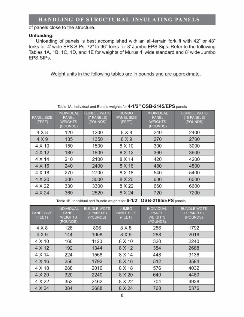
The building site should be relatively level, free of debris, and accessible to a 70’ long tractor-trailer truck. Allowances must be made for truck maneuverability and level stacking of panels close to the structure.
Unloading:Unloading of panels is best accomplished with an all-terrain forklift with 42” or 48”
forks for 4’ wide EPS SIPs; 72” to 96” forks for 8’ Jumbo EPS Sips. Refer to the following Tables 1A, 1B, 1C, 1D, and 1E for weights of Murus 4’ wide standard and 8’ wide Jumbo EPS SIPs.
Weight units in the following tables are in pounds and are approximate.
PANEL SIZE (FEET)
INDIVIDUAL PANEL
WEIGHTS (POUNDS)
BUNDLE WGTS (7 PANELS) (POUNDS)
JUMBOPANEL SIZE
(FEET)
INDIVIDUALPANEL
WEIGHTS(POUNDS)
BUNDLE WGTS(10 PANELS)(POUNDS)
4 X 8 120 1200 8 X 8 240 24004 X 9 135 1350 8 X 9 270 2700
4 X 10 150 1500 8 X 10 300 30004 X 12 180 1800 8 X 12 360 36004 X 14 210 2100 8 X 14 420 42004 X 16 240 2400 8 X 16 480 48004 X 18 270 2700 8 X 18 540 54004 X 20 300 3000 8 X 20 600 60004 X 22 330 3300 8 X 22 660 66004 X 24 360 2520 8 X 24 720 7200
PANEL SIZE (FEET)
INDIVIDUAL PANEL
WEIGHTS (POUNDS)
BUNDLE WGTS (7 PANELS) (POUNDS)
JUMBOPANEL SIZE
(FEET)
INDIVIDUALPANEL
WEIGHTS(POUNDS)
BUNDLE WGTS(7 PANELS)(POUNDS)
4 X 8 128 896 8 X 8 256 17924 X 9 144 1008 8 X 9 288 2016
4 X 10 160 1120 8 X 10 320 22404 X 12 192 1344 8 X 12 384 26884 X 14 224 1568 8 X 14 448 31364 X 16 256 1792 8 X 16 512 35844 X 18 288 2016 8 X 18 576 40324 X 20 320 2240 8 X 20 640 44804 X 22 352 2462 8 X 22 704 49284 X 24 384 2688 8 X 24 768 5376
HANDLING OF STRUCTUR AL INSULATING PANELS
Table 1A. Individual and Bundle weights for 4-1/2” OSB-2145/EPS panels
Table 1B. Individual and Bundle weights for 6-1/2” OSB-2165/EPS panels

9
PANEL SIZE (FEET)
INDIVIDUAL PANEL
WEIGHTS (POUNDS)
BUNDLE WGTS (6 PANELS) (POUNDS)
JUMBOPANEL SIZE
(FEET)
INDIVIDUALPANEL
WEIGHTS(POUNDS)
BUNDLE WGTS(6 PANELS)(POUNDS)
4 X 8 134 804 8 X 8 268 16084 X 9 151 906 8 X 9 302 1812
4 X 10 168 1008 8 X 10 336 20164 X 12 202 1212 8 X 12 404 24244 X 14 235 1410 8 X 14 470 28204 X 16 269 1614 8 X 16 538 32284 X 18 302 1812 8 X 18 604 36244 X 20 336 2016 8 X 20 672 40324 X 22 370 2220 8 X 22 740 44404 X 24 403 2418 8 X 24 806 4836
PANEL SIZE (FEET)
INDIVIDUAL PANEL
WEIGHTS (POUNDS)
BUNDLE WGTS (5 PANELS) (POUNDS)
JUMBOPANEL SIZE
(FEET)
INDIVIDUALPANEL
WEIGHTS(POUNDS)
BUNDLE WGTS(5 PANELS)(POUNDS)
4 X 8 144 720 8 X 8 288 14404 X 9 162 810 8 X 9 324 1620
4 X 10 180 900 8 X 10 360 18004 X 12 216 1080 8 X 12 432 21604 X 14 252 1260 8 X 14 504 25204 X 16 288 1440 8 X 16 576 28804 X 18 324 1620 8 X 18 648 32404 X 20 360 1800 8 X 20 720 36004 X 22 396 1980 8 X 22 792 39604 X 24 432 2160 8 X 24 864 4320
PANEL SIZE (FEET)
INDIVIDUAL PANEL
WEIGHTS (POUNDS)
BUNDLE WGTS (4 PANELS) (POUNDS)
JUMBOPANEL SIZE
(FEET)
INDIVIDUALPANEL
WEIGHTS(POUNDS)
BUNDLE WGTS(4 PANELS)(POUNDS)
4 X 8 152 608 8 X 8 304 12164 X 9 171 684 8 X 9 342 1368
4 X 10 190 760 8 X 10 380 15204 X 12 228 912 8 X 12 456 18244 X 14 266 1064 8 X 14 532 21284 X 16 304 1216 8 X 16 608 24324 X 18 342 1368 8 X 18 684 27324 X 20 380 1520 8 X 20 760 30404 X 22 418 1672 8 X 22 836 33444 X 24 456 1824 8 X 24 912 3648
Table 1D. Individual and Bundle weights for 10-1/4” OSB-21105/EPS panels
Table 1C. Individual and Bundle weights for 8-1/4” OSB-2185/EPS panels
Table 1E. Individual and Bundle weights for 12-1/4” OSB-21125/EPS panels
10
Safety:
Panels can be heavy, so for safer and faster installation, it is recommended that a crane be used when handling larger panels. Always wear OSHA approved eye, ear, and head protection gear when routing, cutting, or installing panels.
Protecting SIPs:
Murus SIPs are manufactured with APA (American Plywood Association) rated Exposure-1 or equivalent OSB (meeting PS 2-04 requirements) skins, and are not designed to be exposed to the weather beyond normal building/construction time. It is recommended that Murus SIPs be covered before and after construction to avoid damage caused by exposure to the elements.
Murus SIPs are delivered to the building site in bundles wrapped in a polyethylene covering. Off-load the panels onto level risers which are tall enough to create an air flow beneath the bundle. This will help inhibit ground moisture from condensing on the underside of the bundle and polyethylene wrap. Insure that the bundles remain tightly wrapped until panels are installed, and re-cover partially used bundles.
Since Murus SIPs are not intended to be left exposed to the weather, once they are installed it is imperative to immediately apply code-approved, weatherproof roofing, siding and trim, so that the SIPs are completely covered and protected from rain, snow, high moisture, and ultraviolet light. For more information, refer to the Roofing and Siding sections of this guide beginning on Page 61.

11
Extended Storage:
For extended storage of SIPs, Murus recommends placing the wrapped bundles of panels in a fully enclosed structure that will provide protection from exposure to wind,rain, moisture, and ultraviolet light. Be sure the storage surface or storage area of the structure is level and sound. Murus recommends limiting stacks to two (2) bundles high,with risers installed under and between the bundles, spaced no more than 2’ apart. (SeeFigure 2, below). If an enclosed structure is not available, the bundles should remain in their original packaging and be covered with durable, waterproof tarps.
2’-0”
or Less
Figure 2. Panel Storage

12
Technical Information:
This manual is provided to facilitate installation of Murus EPS SIPs. Read the manual, paying particular attention to construction techniques, details, notes, etc., that may pertain to your project. Doing so will help ensure a smooth panel installation.
Technical Drawings:
Become familiar with the panel layout and technical drawings. Panel drawings are used to present the four aspects of the panel system: the individual panels, their dimensions, how they fit into the scheme of the building, and connection and installation details.
A typical set of Murus panel drawings includes exterior wall elevations, roof plan, special features such as eave, rake, and connection details, overall dimensions, and string-line dimensions. Rough opening dimensions are labeled and used to reference window and door sizes, locations, etc.
Note: Technical drawings should be properly prepared and engineered by a qualified design professionals.
Special Tools:
Cutting and installing SIPs requires special tools. Cutting of most SIPs (depending on panel thickness) can be accomplished with either a 7-¼” circular saw by cutting from both sides (finish cutting of the foam core with a hand saw), a 16” circular saw (with carbide-tip blade), or a special bar and chain attachment for a 7-¼” circular saw.
Routing (removal of the foam core) of SIPs is required for installation of key splines, 2x inlet nailers, plates, headers, etc. The routing of the panels may be accomplished in one of two ways: either with a hot wire cutting tool, or with a mechanical panel router.
Hot Knife:The hot wire cutting tool, also called a hot knife or foam scoop, is a specially designed
tool for cutting EPS foam. This specialized tool is available for purchase through various sources including Demand Products, Inc., 1055 Nine North Drive, Alpharetta, GA 30004 USA, phone # 800-325-7540, www.demandproducts.com.
PR EPAR ING FOR CONSTRUCTION

13
The Panel Router
The panel router is a specially adapted tool for removing the foam core edges of Murus SIPs to accommodate inlet plates and nailers. The panel router should not be confused with a traditional hand-held router.
Fasteners:
Typical fasteners used in SIP construction include: 1) 8d or 16d coated ring shank nails; 2) 6”, 7”, 8”, 9”, 10”, 12”, or 14” corrosion-resistant ring shank nails or corrosion-resistant panel screws; 3) 3” and 3 ½” coated screws, or other approved material fastener for use with pressure-treated wood.
Figure 3. Panel Router

14
Table 2. Fastening Schedule
*WALL PANEL CONNECTIONS
APPLICATION FASTENER SPACINGBottom inlet nailer to pressure
treated sill plate3” coated screws 6” O.C. staggered or offset
Top plate to top inlet nailer 16d coated nails 6” O.C. staggered or offsetBottom inlet nailer to platform floor
system3 1/2” coated screws 6” O.C. staggered or offset
Bottom inlet nailer to wrapped floor system
3” coated screws 6” O.C. staggered or offset
OSB skins to top and bottom inlet nailers
8d coated corrosion-resistant ring shank nails
4” - 6” O.C.
OSB skins to posts and headers 8d coated corrosion-resistant ring shank nails
4” - 6” O.C.
OSB skins to inlet nailers 8d coated corrosion-resistant ring shank nails
6” - 8” O.C.
OSB skins to plywood keysplines 8d coated corrosion-resistant ring shank nails
4” - 6” O.C.
SIP to rim joist and structural support members
Panel screws or panel nails
12” - 16” O.C.
Wall corner connections Panel screws or panel nails
12” - 16” O.C.
*ROOF PANEL CONNECTIONS
APPLICATION FASTENER SPACINGSIP-to-roof support member
i.e. rafter, purlin, joist16” - 24” O.C. 1 1/2” members Panel screws 18” - 24” O.C.
2’ - 4’ O.C. members Panel screws or panel nails
16” - 24” O.C.
4’ - 6’ O.C. members Panel screws or panel nails
12” - 16” O.C.
6’ - 8’ O.C. members Panel screws or panel nails
8” - 12” O.C.
Roof panel to wall panel Panel screws or panel nails
4” - 16” O.C.
OSB skins to plywood keysplines 8d coated corrosion-resistant ringshank nails
4” - 6” O.C.
*NOTE: These fastening schedules are intended for use in normal wind and loading conditions. High load, high wind, and seismic conditions may require additional fastening. Always refer to the fastener schedule on the Panel Layout drawings for the panel fastener size and spacing for your project. All fastener spacing should be reviewed by a design professional. Murus recommends the use of coated/corrosion-resistant fasteners wherever the fastener may be directly or indirectly exposed or subjected to moisture.

15
2X Inlet Nailers, Plates and Keysplines:
All plates and nailers are to be kiln-dried to a moisture content of 19% or less, SPF #2 grade or better, unless a higher grade is specified in the panel layout or project drawings. All key splines shall be 5/8” exterior grade plywood unless otherwise specified.
Factory Pre-Cutting of Panels:
Pre-cutting of panels at the Murus manufacturing facility saves installation time and greatly reduces on-site scrap and disposal requirements. Wall and roof panels are cut to size utilizing Murus’s state-of-the-art computerized CNC equipment. Factory pre-cutting includes cutting of rough openings for windows and doors, routing to remove foam where nailers, inlet plates, posts, and headers are to be installed, and cutting and trimming panel edges where needed. Installation of nailers, inlet plates, posts, and headers is done on site.
On-Site Cutting of Panels:
NOTE: Power tools should only be operated by qualified individuals. Special care and safety precautions should always be used when operating power tools. Guard against electric shock by wearing rubber gloves and non-skid footwear when working outdoors. A ground fault circuit interrupter-protected power line must be used when working under damp or wet conditions. Do not wear jewelry or loose clothing. Wear protective hair covering to contain long hair. Wear safety goggles or safety glasses with side shields. Wear hearing protection during extended use of power tools, and dust mask for dusty operations. Follow the instructions for safe power tool operation as stated in the manufacturer’s Operator’s Manual.
Cutting panels on the jobsite requires an elevated sturdy work station where panels can easily and safely be handled, cut, and routed. Cutting the panel is done with either a 16” hand-held circular saw or a beam cutting attachment for a circular saw in one pass, or with a 7 ¼” circular saw, from both sides.
NOTE: Angled cuts may require cutting from both sides depending on the depth of the cut required. When cutting rough openings, cut to the line, not past. Finish cutting the inside corners of the bottom skin and foam with a hand saw.
On-Site Routing:
Installation of nailers, inlet plates, posts, and headers require the removal of the foam core from between the panel skins. This process is referred to as routing.
Routing should always be done from the exterior side of the SIP so that an even, consistent channel is cut from panel to panel.

16
When routing inside corners such as a rough opening, a small hand saw or knife may be used to square and remove the foam that the router bit or hot knife cannot reach. This squaring of the inside corners ensures that the nailers and plates fit properly.
When using a hot wire cutting tool, it should be passed along the EPS core at a slow and consistent speed to ensure an accurate cut. If the core material starts to melt, the speed should be increased. If the cut is rough and uneven, the speed should be reduced. When routing inside corners such as a rough opening, a small hand saw or knife may be used to square and remove the foam that the router bit or hot knife cannot reach. This squaring of the inside corners ensures that the nailers and plates fit properly.

17
Foundation Systems:
Foundation Systems:
Murus in no manner warrants or promotes the use of any particular foundation system. However, Murus recommends the use of the following guidelines when planning or speci-fying foundation systems:
The foundation systems used with SIP construction are similar to any acceptable foundation used in typical residential or commercial construction, given the proper site preparation, soil bearing capacity, installation, etc.
The outside dimensions of the SIPs should match the outside dimensions of the slab or foundation walls so that the SIPs will ultimately bear entirely on the foundation, and so that the siding will extend slightly past the foundation walls or slab.
Slight inaccuracies in the foundation wall or slab dimensions should be corrected when setting the sill plates. Sill plates must be cut to the correct dimensions, set level and square, and bear completely on the foundation wall or slab.
All foundation systems should be reviewed, and/or designed, by a professional engineer to insure structural adequacy. Special attention should be given to axial/compressive point loading.
Contact with Masonry:
As with any untreated wood product, It is imperative to prevent contact between SIPs and masonry. A pressure-treated plate must be located between a SIP and any masonry or foundation work.
Sill Details:
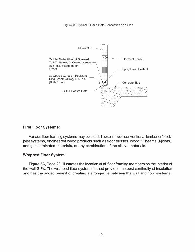
Figures 4A and 4B, Page 18, illustrate typical sill connection, floor framing, and panel connections at the foundation wall. The sill connection serves two major functions. First, it serves to resist lateral loads encountered from wind and seismic loading, allowing the panels to react with a diaphragm action. Secondly, it resists uplift forces induced by wind loads on the walls and roof(s). The sill plate is typically secured to the foundation with either strapping or anchor bolts at 4” o.c. or less. Refer to your local building codes for proper sill plate attachment. Murus recommends the use of insect shields and foam sill seal between all masonry and sill plates. Figure 4C, Page 19, illustrates the panel connection typically used with a concrete slab.
FOUNDATION SYSTEMS AND FLOOR FR AMING

18
Floor Joists
Electrical Chase
Murus SIP
Rim Joist
Panel Fastener PerTable 2 on Page 14
Spray Foam Sealant
2x Inlet Nailer Glued & ScrewedTo Sill Plate w/ 3" Coated Screws@ 6" o.c. Staggered or Offset
8d Coated Corrosion-ResistantRing Shank Nails @ 4"-6" o.c.
2x P.T. Sill Plate
Foundation Wall
Subfloor
2x Inlet Nailer Glued & ScrewedTo Subfloor w/ 3 1/2" Coated Screws@ 6" o.c. Staggered or Offset
8d Coated Corrosion-Resistant Ring Shank Nails @ 4"-6" o.c.(Both Sides)
Rim Joist
Subfloor
Electrical Chase
Murus SIP
Spray Foam Sealant
2x P.T. Sill Plate
Foundation Wall
Floor Joists
Figure 4A. Typical Sill, Bottom Inlet Plate and Wrapped Floor Connection on a Foundation Wall
Figure 4B. Typical Sill, Plate, and Platform Floor Connection on a Foundation Wall
19
Various floor framing systems may be used. These include conventional lumber or “stick” joist systems, engineered wood products such as floor trusses, wood “I” beams (I-joists), and glue laminated materials, or any combination of the above materials.
Wrapped Floor System:
Figure 5A, Page 20, illustrates the location of all floor framing members on the interior of the wall SIPs. The wrapped floor system method provides the best continuity of insulation and has the added benefit of creating a stronger tie between the wall and floor systems.
Concrete Slab
Spray Foam Sealant
Electrical Chase
2x P.T. Bottom Plate
8d Coated Corosion-ResistantRing Shank Nails @ 4"-6" o.c.(Both Sides)
2x Inlet Nailer Glued & ScrewedTo P.T. Plate w/ 3" Coated Screws@ 6" o.c. Staggered or Offset
Murus SIP
Figure 4C. Typical Sill and Plate Connection on a Slab
First Floor Systems:

20
Platform Floor System:
Figure 5B, below, illustrates platform framed floor systems which are located beneath or intermittent to the SIP wall(s) with the SIP bearing on the floor system.
Top Mount Joist Hanger
2x Top Plate Glued & Nailed To Inlet Nailer w/ 16d Coated Nails @ 6" o.c. Staggered or Offset
Floor Joist
Murus SIP
Subfloor
Spray Foam Sealant
2x Inlet Nailer Glued & ScrewedTo Subfloor w/ 3 ½" Coated Screws.@ 6" o.c. Staggered or Offset
Spray Foam Sealant
2x Inlet Nailer
8d Coated Corrosion-Resistant RingShank Nails @ 4"-6" o.c. (Both Sides)
8d Coated Corrosion-Resistant RingShank Nails @ 4"-6" o.c. (Both Sides)
Floor Joists
Electrical Chase
Murus SIP
Rim Joist
Panel Fastener PerTable 2 on Page 14
Spray Foam Sealant
2x Inlet Nailer Glued & ScrewedTo Sill Plate w/ 3" Coated Screws@ 6" o.c. Staggered or Offset
8d Coated Corrosion-Resistant RingShank Nails @ 4"-6" o.c.
2x P.T. Sill Plate
Foundation Wall
Subfloor
Figure 5A. Typical Wall Section with Wrapped Floor Systems

21
2x Inlet Nailer Glued & ScrewedTo Subfloor w/ 3 ½" Coated. Screws@ 6" o.c. Staggered or Offset
8d Coated Corrosion-Resistant RingShank Nails @ 4"-6" o.c. (Both Sides)
2x Top Plate Glued & Nailed To 2x Inlet Nailer w/ 16d Coated Nails@ 6" o.c. Staggered or Offset
2x Inlet Nailer
Rim Board
Spray Foam Sealant
Floor Joists
Murus SIP
Subfloor
Spray Foam Sealant
8d Coated Corrosion-Resistant Ring ShankNails @ 4"-6" o.c.(Both Sides)
2x Inlet Nailer Glued & ScrewedTo Subfloor w/ 3 ½" Coated. Screws@ 6" o.c. Staggered or Offset
8d Coated Corrosion-Resistant Ring Shank Nails @ 4"-6" o.c.(Both Sides)
Rim Joist
Subfloor
Electrical Chase
Murus SIP
Spray Foam Sealant
2x P.T. Sill Plate
Foundation Wall
Floor Joists
Figure 5B. Typical Wall Section with Platform Framed Floor Systems
22
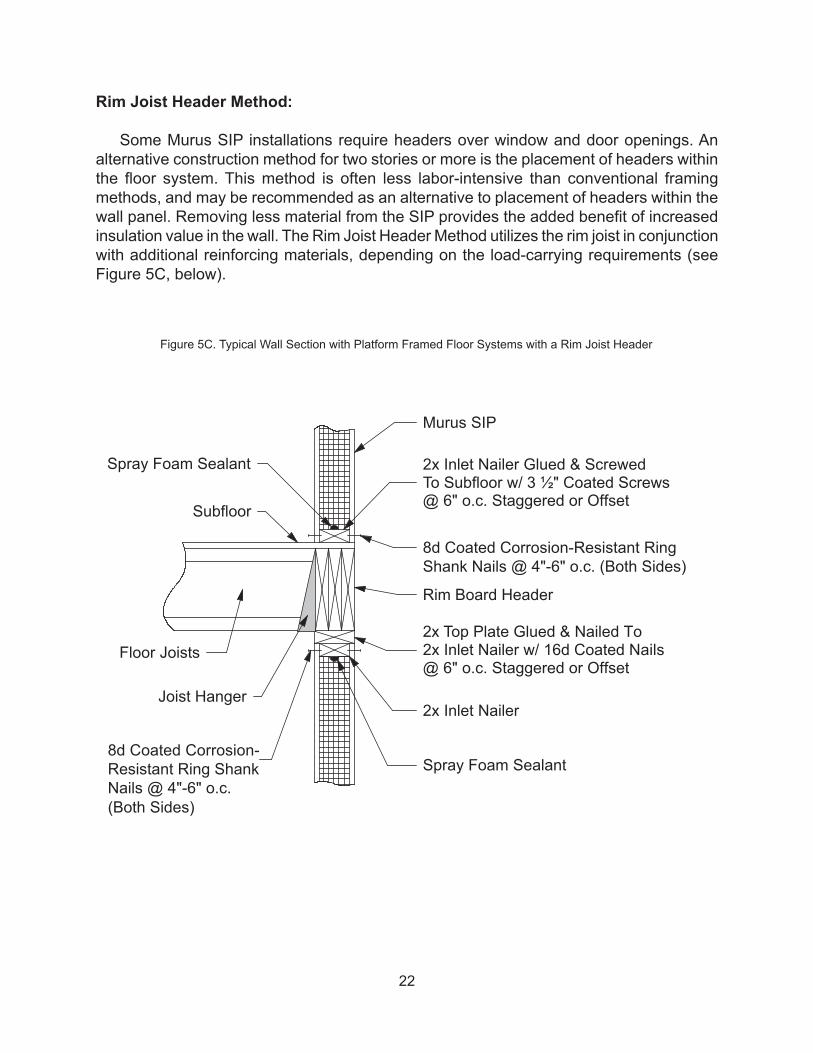
Rim Joist Header Method:
Some Murus SIP installations require headers over window and door openings. An alternative construction method for two stories or more is the placement of headers within the floor system. This method is often less labor-intensive than conventional framing methods, and may be recommended as an alternative to placement of headers within the wall panel. Removing less material from the SIP provides the added benefit of increased insulation value in the wall. The Rim Joist Header Method utilizes the rim joist in conjunction with additional reinforcing materials, depending on the load-carrying requirements (see Figure 5C, below).
2x Inlet Nailer Glued & ScrewedTo Subfloor w/ 3 ½" Coated Screws@ 6" o.c. Staggered or Offset
8d Coated Corrosion-Resistant RingShank Nails @ 4"-6" o.c. (Both Sides)
2x Top Plate Glued & Nailed To2x Inlet Nailer w/ 16d Coated Nails@ 6" o.c. Staggered or Offset
2x Inlet Nailer
Rim Board Header
Spray Foam Sealant
Floor Joists
Murus SIP
Subfloor
Spray Foam Sealant
8d Coated Corrosion-Resistant Ring ShankNails @ 4"-6" o.c.(Both Sides)
Joist Hanger
Figure 5C. Typical Wall Section with Platform Framed Floor Systems with a Rim Joist Header

23
Full Bearing Surface:
Murus SIP walls must be installed level and plumb. Hence, it is essential that the SIP be installed on a level, continuously supported bearing surface such that the entire SIP (both skins) bears on this surface. If the bearing surface is not level, then either: 1) the bearing surface must be made level, or, 2) the bottom of the SIP must be cut to conform to the bearing surface, ensuring that the SIP is vertical, plumb, and fully bearing.
Joining Panels: For most installations, Murus EPS SIPs are connected to each other using 5/8” x 3”
plywood key splines. To allow insertion of the key splines, the foam core must first be routed to provide a ¾” deep x 1 ½” wide recess. This can be accomplished with a mechanical router or hot wire cutting tool. Once the key spline has been inserted into the recess, it is fastened to the OSB skins with 8d ring shank nails. Please refer to the Fastening Schedule on Page 14.
Double key spline connections are used for structural load bearing applications or where additional racking or shear resistance is required. Single key spline connections are typical in curtain wall applications such as timber frames or structural steel frames where racking or shear resistance is not required.
NOTE: Key spline recesses are usually present in all long panel edges when received from Murus. If a SIP is cut, it may be necessary to rout these key spline recesses in the cut edges.
OSB Panel Skin
EPS Foam Core
OSB Panel Skin
Keyspline Rout
Foam Keyway
Figure 6A. Single Key Spline Profile
INSTALLING STRUCTUR AL INSULATING PANELS

24
Sealing with Spray Foam:
Sealing Murus SIPs with spray foam is a very critical installation step, and great care should be taken to properly complete this portion of the installation. The spray foam is used to eliminate or prevent the infiltration of air and moisture through the panel joints and connections. The spray foam also creates a bond between the two surfaces (foam-to-foam or foam-to-wood), resulting in a stronger connection. Failure to properly seal panel joints and connections may result in energy losses, damage to the SIP, and affect the panel warranty.
All occurrences of foam-to-foam contact are sealed with liberal amounts of spray foam as the panels are installed. All occurrences of foam-to-wood contact, such as plates, nailers, etc., are also sealed with liberal amounts of spray foam as the members are installed. NOTE: In colder weather, it is important to keep the spray foam from freezing. Keep spray foam warm by storing in a heated location. Spray foam works best at temperatures above 50° F.
After the panels have been installed, the foam channel must be filled with spray foam (see Figure 6B and 6C, above). After installation is complete and prior to applying exterior or interior coverings, 3/8” ø holes should be drilled along the panel joint (either on the interior or the exterior) at approximately 12” to 18” centers and to the depth of the foam channel, avoiding wire chase locations. Once holes have been drilled the entire length
Keyspline Rout
Foam Keyway
Keyspline Rout
OSB Panel Skin
EPS Foam Core
OSB Panel Skin
8d Coated, Corrosion-ResistantRing Shank Nails @ 4"-6" o.c.
5/8"x 3" PlywoodKeysplines (Both Sides)
Spray Foam Sealant
8d Coated, Corrosion-ResistantRing Shank Nails @ 4"-6" o.c.
Figure 6C. Double Key Spline Connection Detail
Figure 6B. Double Key Spline Profile

25
of the panel joint, start at the bottom of the joint and insert the spray foam applicator so that the tip is approximately half the depth to the foam channel. Begin filling the foam channel by squeezing the trigger on the foam applicator. As the foam channel fills, foam will travel up the foam channel and be visible in the next hole above. Release the trigger and slowly remove the foam applicator from the filled hole. NOTE: As the foam cures, it will continue to squeeze out of the drilled hole. This is to be expected. Repeat the foam application procedure, moving up the panel joint, until all holes along the joint have been filled. Continue to repeat the entire procedure until all panel joints have been sealed. NOTE: The foam channel is only provided on the long edges of the SIP. If a panel joint does not have a foam channel, it is still required to apply liberal amounts of spray foam to all abutting panel edges during installation, if they are present. Failure to do so will not provide a complete seal at these locations. NOTE: Application of the spray foam sealant after installation and utilizing the foam channel will result in a panel joint that is sealed in the final, or in-place position. When properly applied, this provides an excellent seal against air and moisture infiltration.
Spray foam is applied around windows and doors to prevent air infiltration and moisture transfer. It is strongly recommended that a minimally-expanding spray foam be used to fill the cavity with 3 or more small applications until the cavity is filled. IMPORTANT: Allow each application of foam to cure (12-24 hours) before applying the next layer. This foaming procedure will help reduce the possibility of binding and/or bowing of the jambs due to the expansion of the foam. For more information, see Installing Doors, Windows, and Skylights on Page 51.
Spray foam sealant, available in hand-held canisters with a detachable applicator, is provided by the case with most Murus panel orders. Closely follow precautions and directions on the container for safe handling and to optimize its use.
26
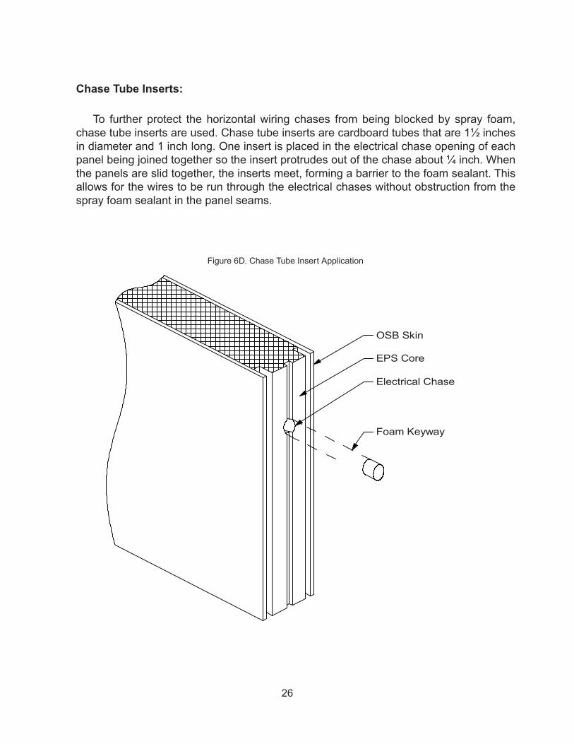
Chase Tube Inserts:
To further protect the horizontal wiring chases from being blocked by spray foam, chase tube inserts are used. Chase tube inserts are cardboard tubes that are 1½ inches in diameter and 1 inch long. One insert is placed in the electrical chase opening of each panel being joined together so the insert protrudes out of the chase about ¼ inch. When the panels are slid together, the inserts meet, forming a barrier to the foam sealant. This allows for the wires to be run through the electrical chases without obstruction from the spray foam sealant in the panel seams.
Foam Keyway
Electrical Chase
EPS Core
OSB Skin
Figure 6D. Chase Tube Insert Application

27
SIP Tape:
SIP tape is an adhesive-backed non-permeable membrane that is installed on the interior surface of a panel seam. Its purpose is to seal the seam from air and moisture infiltration from the interior environment. SIP tape is available from The Murus Company, Inc., but it is our experience that spray foam sealant, when applied properly, is the most economical way to seal panel joints. It is not recommended to use SIP tape alone to seal panel joints.
Construction Adhesives and Caulking Sealants:
Construction adhesives are used where wood members, such as nailers, plates, etc., come into contact with another wood member. Adhesives provide the best bond and seal between wood products, whereas spray foam provides the best bond and seal between foam and wood products.
Caulking sealants (Murus recommends siliconized caulk for durability) can be used to further seal panel seams on the interior of the structure wherever panel seams are accessible. This further aids in reducing moisture and vapor transmission.
PanelJoint
Key SplinesFoam Keyway
3/8” Foam KeywayAccess Hole
12”- 18” o.c.
Figure 6E. EPS Panel Exterior View

28
Mastic:
Mastic is a product used by some SIP manufacturers to seal panel joints against air and moisture infiltration. It comes in tubes similar to caulk and most construction adhesives. Mastic does not expand to fill voids the way spray foam sealant does. Using mastic is more labor-intensive than if spray foam sealant is used as outlined in this manual.
Plates, Inlet Nailers, Posts, Headers, and Splines:
The installation of these materials, in the areas where the foam has been routed to allow for their insertion, is preceded by applying a liberal amount of spray foam sealant into the recess. Nailing and fastening of these materials to the OSB skins is accomplished with coated ring shank nails, in accordance with the Fastening Schedule on Page 14. See Figure 7A, below, for inlet installation detail.
Sills, plates, inlets, posts, headers, and splines serve the important structural functions of resisting uplift, racking and flexure loading. The craft and care given to this installation is important. See Figures 5A, 5B, and 5C on Pages 20, 21, and 22, as well as the following descriptions and illustrations.
Bottom Inlet Nailer:
A 2x bottom inlet nailer must be located in the bottom of all wall SIPs. With a wrapped first floor system, this nailer is securely fastened to the pressure-treated sill plate with 3” coated screws located 6” on center and with construction adhesive between the nailer and the plate. For platform framing or second floor applications, use 3½” coated screws fastened through the subfloor and into the rim board and floor joists.
The bottom of the wall SIP must be routed to remove the foam core to a depth of 1½”, such that the OSB skins of the SIP will bear fully on the pressure-treated sill plate or subfloor. Once the SIP is placed over the inlet nailer, the OSB skins are nailed to the inlet plate with 8d coated corrosion-resistant ring shank nails 4” - 6” on center from both sides (from the exterior only in the case of a “wrapped” deck). Liberal amounts of spray foam must be applied to the inlet plate prior to installing the SIP.
Foam Sealant 8d Coated, Corrosion-ResistantRing Shank Nails @ 6"- 8" o.c.(Both Sides)
2X Inlet NailerMurus SIP
Figure 7A. Typical Inlet Nailer Connection Detail

29
When utilizing the wrapped first floor system (Figure 5A, Page 20), the bottom of the SIP should also be nailed or screwed into the rim joist. Install the fasteners near the top of the rim joist at 12” - 16” on center. Please refer to the Fastening Schedule on Page 14, and Figure 4A on Page 18.
IMPORTANT: Do not fully set these fasteners into the rim board until the tops of the panels are plumb and fastened to the second floor or roof system.
Top Inlet Nailer:
Typically, a wall SIP will have a 2x (width is dependent on the thickness of the foam core) top inlet nailer installed so that the vertical panel-to-panel joints are offset from the inlet nailer butt joints. The inlet nailer is housed in a 1-½” deep rout in the foam core at the top of the panel. During installation of the inlet nailer, spray foam is liberally applied between the foam core and wood nailer. The inlet nailer is attached to the SIP by nailing through both OSB skins with 8d coated corrosion-resistant ring shank nails at 4” - 6” on center, from both sides (see Figure 7B, Page 30). NOTE: If the inlet nailer is not a continuous 2X which spans the full length of the wall, it is very important to make sure that the butt joints of the inlet nailers are offset from the vertical panel-to-panel joints.
Load Bearing Top Plate:
The top plate is located directly on top of the top inlet nailer and provides bearing for 1) second floor framing, 2) roof framing, and/or 3) second floor wall SIPs. The top plate is usually 2X material ripped to the width of the panel (depends on the thickness of the panel being used), so that it bears fully on both inside and outside skins of the panel. Construction adhesive is applied between the inlet nailer and the top plate. The top plate is then nailed to the inlet nailer with 16d coated nails at 6” on center in a staggered or offset pattern. (See Figure 7B, Page 30.)
30
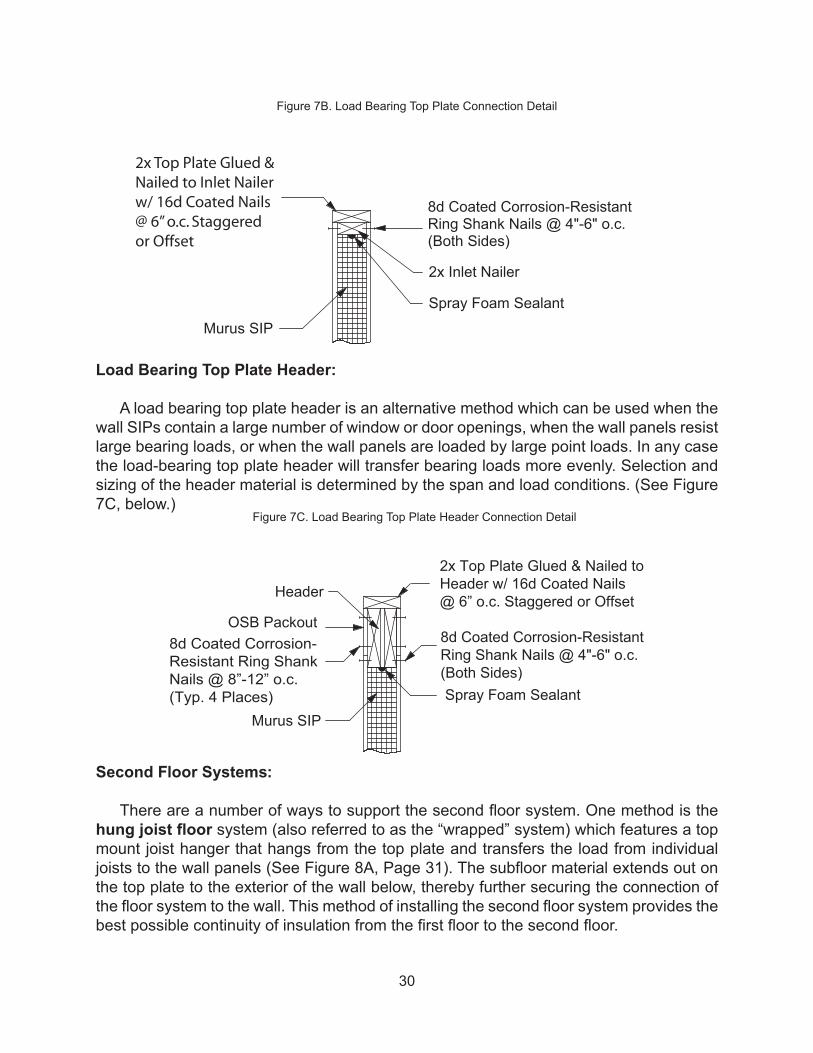
Load Bearing Top Plate Header:
A load bearing top plate header is an alternative method which can be used when the wall SIPs contain a large number of window or door openings, when the wall panels resist large bearing loads, or when the wall panels are loaded by large point loads. In any case the load-bearing top plate header will transfer bearing loads more evenly. Selection and sizing of the header material is determined by the span and load conditions. (See Figure 7C, below.)
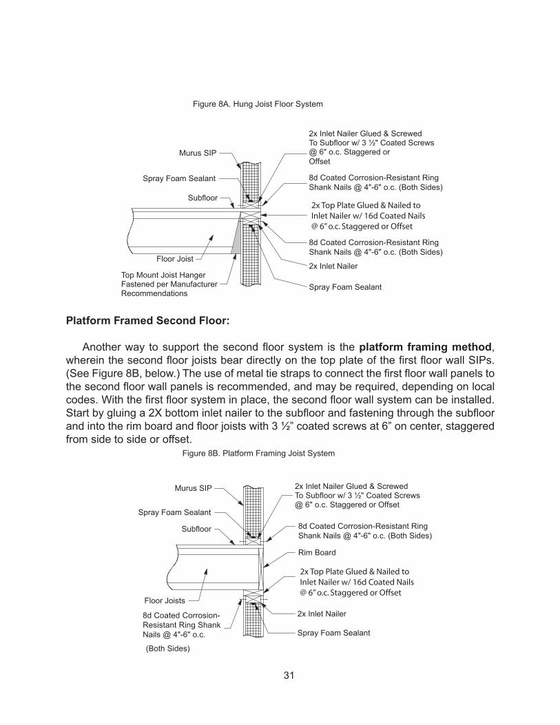
Second Floor Systems:
There are a number of ways to support the second floor system. One method is the hung joist floor system (also referred to as the “wrapped” system) which features a top mount joist hanger that hangs from the top plate and transfers the load from individual joists to the wall panels (See Figure 8A, Page 31). The subfloor material extends out on the top plate to the exterior of the wall below, thereby further securing the connection of the floor system to the wall. This method of installing the second floor system provides the best possible continuity of insulation from the first floor to the second floor.
2x Inlet Nailer
Murus SIP
8d Coated Corrosion-ResistantRing Shank Nails @ 4"-6" o.c.(Both Sides)
Spray Foam Sealant
2x Top Plate Glued &Nailed to Inlet Nailerw/ 16d Coated Nails@ 6” o.c. Staggeredor Offset
Header
Murus SIP
8d Coated Corrosion-ResistantRing Shank Nails @ 4"-6" o.c.(Both Sides)Spray Foam Sealant
2x Top Plate Glued & Nailed toHeader w/ 16d Coated Nails@ 6” o.c. Staggered or Offset
OSB Packout8d Coated Corrosion-Resistant Ring ShankNails @ 8”-12” o.c.(Typ. 4 Places)
Figure 7C. Load Bearing Top Plate Header Connection Detail
Figure 7B. Load Bearing Top Plate Connection Detail
31
Platform Framed Second Floor: Another way to support the second floor system is the platform framing method,
wherein the second floor joists bear directly on the top plate of the first floor wall SIPs. (See Figure 8B, below.) The use of metal tie straps to connect the first floor wall panels to the second floor wall panels is recommended, and may be required, depending on local codes. With the first floor system in place, the second floor wall system can be installed. Start by gluing a 2X bottom inlet nailer to the subfloor and fastening through the subfloor and into the rim board and floor joists with 3 ½” coated screws at 6” on center, staggered from side to side or offset.
Top Mount Joist HangerFastened per ManufacturerRecommendations
Floor Joist
Murus SIP
Subfloor
Spray Foam Sealant
2x Inlet Nailer Glued & ScrewedTo Subfloor w/ 3 ½" Coated Screws@ 6" o.c. Staggered orOffset
Spray Foam Sealant
2x Inlet Nailer
8d Coated Corrosion-Resistant RingShank Nails @ 4"-6" o.c. (Both Sides)
8d Coated Corrosion-Resistant RingShank Nails @ 4"-6" o.c. (Both Sides)
2x Top Plate Glued & Nailed toInlet Nailer w/ 16d Coated Nails@ 6” o.c. Staggered or Offset
2x Inlet Nailer Glued & ScrewedTo Subfloor w/ 3 ½" Coated Screws@ 6" o.c. Staggered or Offset
8d Coated Corrosion-Resistant RingShank Nails @ 4"-6" o.c. (Both Sides)
2x Inlet Nailer
Rim Board
Spray Foam Sealant
Floor Joists
Murus SIP
Subfloor
Spray Foam Sealant
8d Coated Corrosion-Resistant Ring ShankNails @ 4"-6" o.c.
(Both Sides)
2x Top Plate Glued & Nailed toInlet Nailer w/ 16d Coated Nails@ 6” o.c. Staggered or Offset
Figure 8A. Hung Joist Floor System
Figure 8B. Platform Framing Joist System

32
Girder/Beam Housing:Girders or beams on the interior of the structure may be supported and housed in a
girder/beam pocket in the exterior SIP wall. Depending on the loading of a beam or girder, it is housed in the panel with or without an inlet bearing post (See Figure 9, below.)
2x Inlet Nailer Glued& Nailed to Beam(All Sides)
Murus SIP
8d Coated Corrosion-Resistant Ring ShankNails @ 4"-6" o.c.(Both Sides)
Spray Foam Sealant
Beam
2x Inlet Nailer Glued& Nailed to Beam(Top & Sides)
Murus SIP
8d Coated Corrosion-Resistant Ring ShankNails @ 4"-6" o.c.(Both Sides)
Spray Foam Sealant
Beam
Built-up or Solid PostLet Into Panel
Beam Pocket w/o PostViewed from Exterior
Beam Pocket w/ PostViewed from Exterior
Figure 9. Girder/Beam Housing (with and without post)

33
Spline Joints:
Spline joints serve many different functions in SIP construction. Primarily, splines are used to connect Murus EPS SIPs to each other. The following Figures 10A, 10B, 10C, 10D, and 10E are examples that address these functions.
Murus SIP
5/8"x 3" PlywoodKeyspline
Spray Foam Sealant
8d Coated Corrosion-Resistant Ring ShankNails @ 4"-6" o.c.
8d Coated Corrosion-Resistant Ring ShankNails @ 4"-6" o.c.
5/8"x 3" PlywoodKeysplines (Both Sides)
Spray Foam Sealant
8d Coated Corrosion-Resistant Ring ShankNails @ 4"-6" o.c.
Figure 10A. Single Key SplineUsed for joining panels in some non load-bearing applications
Figure 10B. Double Key SplineUsed for joining panels in load-bearing applications

34
8d Coated Corrosion-Resistant Ring ShankNails @ 4"-6" o.c.
2x Inlet Nailer
Spray Foam Sealant
8d Coated Corrosion-Resistant Ring ShankNails @ 4"-6" o.c.
Spray Foam Sealant
8d Coated Corrosion-Resistant Ring ShankNails @ 4"-6" o.c.(Both Sides)
Solid or Built-up PostMurus SIP
Spray Foam Sealant
8d Coated Corrosion-Resistant Ring ShankNails @ 4"-6" o.c.(Both Sides)
Solid or Built-up Post Murus SIP
OSB Packout
Figure 10D. Half Housed 4xUsed for joining panels where heavy point load bearing strength is needed
Figure 10E. Fully Housed 4xUsed for rough openings, jack posts under headers, and corners where extra nailing
area or heavier bearing strength is needed
Figure 10C. Half Housed 2xUsed for joining panels in load-bearing applications
with additional point load support

35
Corner Connections:
A 90 degree corner (both inside corner and outside corner) is formed by overlapping the ends of two panels or paneled walls (Figure 11A, below). Both panels require 2x inlet nailers installed in the end of the panels, using liberal amounts of spray foam and 8d coated corrosion-resistant ring shank nails. Next, apply construction adhesive to the inlet which will face the OSB surface of the adjoining panel. Position the panels to form the corner, make sure both panels are plumb and the corner is square, then drive panel fasteners through the exterior panel and into the inlet nailer of the adjoining panel. Refer to Fastening Schedule on Page 14, or to the Panel Layout drawings for fastener size and spacing.
Corners which are not 90 degrees are usually formed by installing beveled inlet nailers in the edges of the adjoining panels (Figure 11B, Page 36).
8d Coated Corrosion-Resistant Ring ShankNails @ 6"-8" o.c.(Both Sides)
2x Inlet Nailer
Murus SIP
Panel Fastener PerTable 2 on Page 14
Spray Foam Sealant
8d Coated Corrosion-Resistant Ring ShankNails @ 6"-8” o.c.(Both Sides)
Construction Adhesive
Figure 11A. Typical Corner

36
Roof Framing Systems:
Manufactured trusses and rafter systems are used over SIP wall construction for many applications. Common rafter and purlin systems may also be used as roof framing structures. An additional advantage of the common rafter or purlin system is that the members can be spaced further apart since the structural capabilities of the roof SIPs allow them to span greater distances.
Stick Framed Roof:
Manufactured trusses or 2x rafters, typically 24” on center, generally bear fully on the top plate of the exterior wall SIP. Follow truss manufacturer’s recommendations for installation and ensure proper fastening to the top plate with appropriate anchors. Beneath the trusses or rafters, Murus recommends installing non-structural ceiling panels. Murus CP-2100 series ceiling panels provide continuous insulation and a complete foam core insulated building envelope. (See Figure 12A below, and 12B, Page 37.)
8d Coated Corrosion-Resistant Ring Shank Nails @ 4"-6" o.c.(Both Sides)
2x Beveled NailersGlued & Nailed Together
Spray Foam SealantMurus SIP
Spray Foam Sealant
Murus SIP
Spray Foam Sealant
Panel Screw (Into Bottom Chordof Roof Framing Member)2x Inlet Nailer
Roof Framing Member
2x Top Plate Glued & NailedTo 2x Inlet Nailer w/ 16dCoated Nails @ 6" o.c.Staggered or Offset
8d Coated Corrosion-Resistant Ring ShankNails @ 4"-6" o.c.(Both Sides)
Spray Foam Sealant
Key Spline Connectionper Figure 10A
Murus Ceiling Panel(OSB/Foam/SB, SB SideAgainst Framing Member)
Figure 11B. Corner Connection with Miter Less Than or Greater Than 90 Degrees
Figure 12A. Stick Framed Roof

37
Purlin Roof System:
The term ‘purlin’ refers to structural roof framing members, typically heavy timbers, glu-lams, or engineered lumber, which are installed in parallel rows up the slope of the roof. The purlins are positioned parallel to the eave of the roof, and the panels are typically applied vertically on the pitch. Each panel should span at least three purlins (simple spans are not recommended). Longer panels also help minimize the number of panel joints, and may also speed installation time. Panel spans, connections, and fastener spacing should be reviewed by a Professional Engineer and/or detailed on Murus panel drawings. See Figures 13A below, 13B, 13C, and 13D, Page 38, and 13E, Page 39.
Murus SIP
Spray Foam Sealant
Panel Screw (IntoBottom Chord of RoofFraming Member)
Murus Ceiling Panel(S Skin Against Framing Member)
Continuous Header
Roof Framing Member
2x Plate Glued & Nailed ToHeader w/ 16d Coated Nails @6" o.c. Staggered or Offset
Spray Foam Sealant
8d Coated Corrosion-Resistant Ring ShankNails @ 4"-6" o.c.(Both Sides)
Figure 12B. Stick Framed Roof with Continuous Header Detail
Figure 13A. Purlin Roof System

38
Panel Fastener PerTable 2 on Page 14
Murus SIPRoof Panel
Spray Foam Sealant
Purlin
Consult Murus or a LicencedDesign Professional forAllowable Panel Span
2x Inlet NailerMurus SIP
Murus SIP Roof Panel
8d Coated Corrosion-Resistant Ring Shank Nails @ 4"-6" o.c. (Both Sides)
8d Coated Corrosion-Resistant Ring ShankNails @ 6"- 8" o.c.(Both Sides)
Spray Foam Sealant
Panel Fastener PerTable 2 on Page 14
2x Inlet Nailer2x Top Plate Glued & NailedTo Inlet Nailer w/ 16d CoatedNails @ 6" o.c. Staggered orOffset
2x Beveled Blocking Glued &Nailed To Top Plate w/ 16dCoated Nails @ 6” o.c.Staggered or Offset
Beveled 2x Inlet NailerMurus SIP
Murus SIP Roof Panel
8d Coated Corrosion-Resistant Ring ShankNails @ 4"-6" o.c.(Both Sides)
8d Coated Corrosion-Resistant Ring ShankNails @ 6"-8” o.c.(Both Sides)
Spray Foam Sealant
Panel Fastener PerTable 2 on Page 14
2x Inlet Nailer
Beveled 2x Top Plate Glued& Nailed to Top Plate w/ 16dCoated Nails @ 6” o.c.Staggered or Offset
Figure 13B. Typical Detail with Purlin Roof System
Figure 13C. Typical Eave Detail for Purlin Roof System with 2X Blocking
Figure 13D. Typical Eave Detail for Purlin System with Beveled Plate and Nailer
39
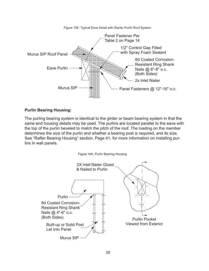
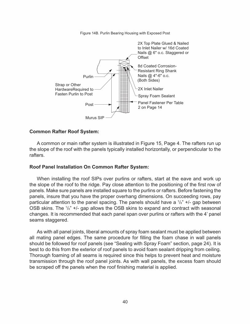
Purlin Bearing Housing:
The purling bearing system is identical to the girder or beam bearing system in that the same end housing details may be used. The purlins are located parallel to the eave with the top of the purlin beveled to match the pitch of the roof. The loading on the member determines the size of the purlin and whether a bearing post is required, and its size. See “Rafter Bearing Housing” section, Page 41, for more information on installing pur-lins in wall panels.
Murus SIP
8d Coated Corrosion-Resistant Ring ShankNails @ 4"-6" o.c.(Both Sides)
Purlin
Built-up or Solid PostLet Into Panel
2X Inlet Nailer Glued& Nailed to Purlin
Purlin PocketViewed from Exterior
Murus SIP
Murus SIP Roof Panel
Panel Fasteners @ 12"-16" o.c.
8d Coated Corrosion-Resistant Ring ShankNails @ 6"-8" o.c.(Both Sides)
1/2" Control Gap Filledwith Spray Foam Sealant
Panel Fastener PerTable 2 on Page 14
2x Inlet Nailer
Eave Purlin
Figure 14A. Purlin Bearing Housing
Figure 13E. Typical Eave Detail with Starter Purlin Roof System
40
Common Rafter Roof System:
A common or main rafter system is illustrated in Figure 15, Page 4. The rafters run up the slope of the roof with the panels typically installed horizontally, or perpendicular to the rafters.
Roof Panel Installation On Common Rafter System:
When installing the roof SIPs over purlins or rafters, start at the eave and work up the slope of the roof to the ridge. Pay close attention to the positioning of the first row of panels. Make sure panels are installed square to the purlins or rafters. Before fastening the panels, insure that you have the proper overhang dimensions. On succeeding rows, pay particular attention to the panel spacing. The panels should have a 1/8” +/- gap between OSB skins. The 1/8” +/- gap allows the OSB skins to expand and contract with seasonal changes. It is recommended that each panel span over purlins or rafters with the 4’ panel seams staggered.
As with all panel joints, liberal amounts of spray foam sealant must be applied between all mating panel edges. The same procedure for filling the foam chase in wall panels should be followed for roof panels (see “Sealing with Spray Foam” section, page 24). It is best to do this from the exterior of roof panels to avoid foam sealant dripping from ceiling. Thorough foaming of all seams is required since this helps to prevent heat and moisture transmission through the roof panel joints. As with wall panels, the excess foam should be scraped off the panels when the roof finishing material is applied.
Murus SIP
Purlin
Post
Strap or OtherHardwareRequired toFasten Purlin to Post
Panel Fastener Per Table2 on Page 14
8d Coated Corrosion-Resistant Ring Shank Nails @ 4"-6" o.c.(Both Sides)
Spray Foam Sealant
2X Inlet Nailer
2X Top Plate Glued & Nailedto Inlet Nailer w/ 16d Coated Nails @ 6" o.c. Staggered orOffset
Figure 14B. Purlin Bearing Housing with Exposed Post

41
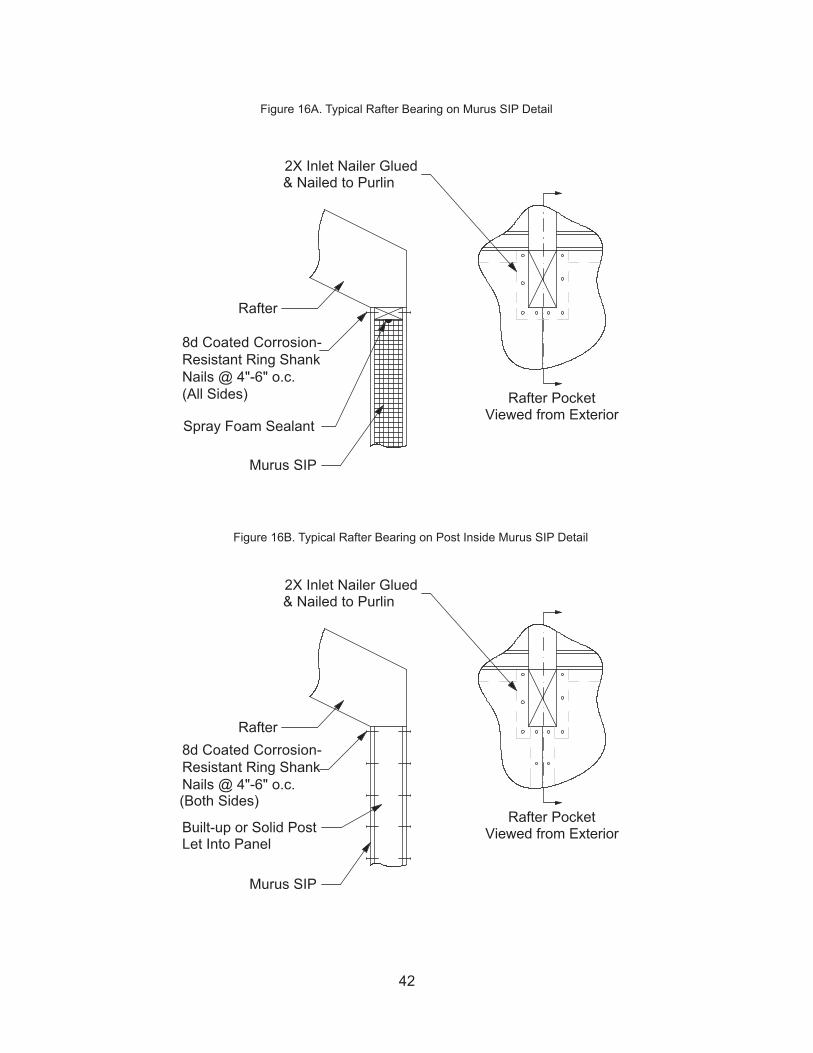
Rafter Bearing Housing:
Similar to the bearing detail for a purlin, a rafter may be housed in the panel to bear on the skins (see Figure 16A, Page 42) or to bear on a post encased in the joint of the panel (Figure 16B, Page 42). In either case, the end of the rafter, regardless of pitch, is collared with 2X material to form a secure connection to the panel. The 2X material is fastened to the rafter with construction adhesive and coated corrosion-resistant ring shank nails. A third instance occurs when the rafter bears on the top plate and possibly the subflooring as well. In this instance (Figures 15, above, and 16C, Page 43), the space between rafters is filled in with SIP material, making sure to apply liberal amounts of spray foam sealant on all sides.
8d Coated Corrosion-Resistant Ring ShankNails @ 4"-6" o.c.(Both Sides)
2x Inlet Nailer
Rafter Beyond to Bearon Top Plate(Strap or Other Hardware Maybe Required to Secure Rafterto Top Plate)
8d Coated Corrosion-Resistant Ring ShankNails @ 6" o.c.(Both Sides)
Panel Fastener per Table 2 on Page 14Into Framing & Infill Panel Inlet Nailer
Panel To InfillBetween Rafters
2x Inlet Nailer Glued & NailedTo Top Plate w/ 16d Coated Nails@ 6" o.c. Staggered or Offset
2x Top Plate Glued & Nailed To Inlet Nailer w/ 16d Coated Nails@ 6" o.c. Staggered or OffsetSpray Foam Sealant
2x Inlet NailerMurus SIP Wall Panel
Murus SIP Roof Panels
Figure 15. Typical rafter system detail
42
Murus SIP
8d Coated Corrosion-Resistant Ring ShankNails @ 4"-6" o.c.(Both Sides)
Rafter
Built-up or Solid PostLet Into Panel
2X Inlet Nailer Glued& Nailed to Purlin
Murus SIP
Spray Foam Sealant
8d Coated Corrosion-Resistant Ring Shank Nails @ 4"-6" o.c.(All Sides)
Rafter
2X Inlet Nailer Glued& Nailed to Purlin
Rafter PocketViewed from Exterior
Rafter PocketViewed from Exterior
Figure 16A. Typical Rafter Bearing on Murus SIP Detail
Figure 16B. Typical Rafter Bearing on Post Inside Murus SIP Detail

43
Cantilevering Roof SIPs:
To create both eave and rake overhangs, the roof panel may be cantilevered beyond the exterior of the wall. Consult with Murus or a licensed Design Professional to determine the extent of overhang that is acceptable.
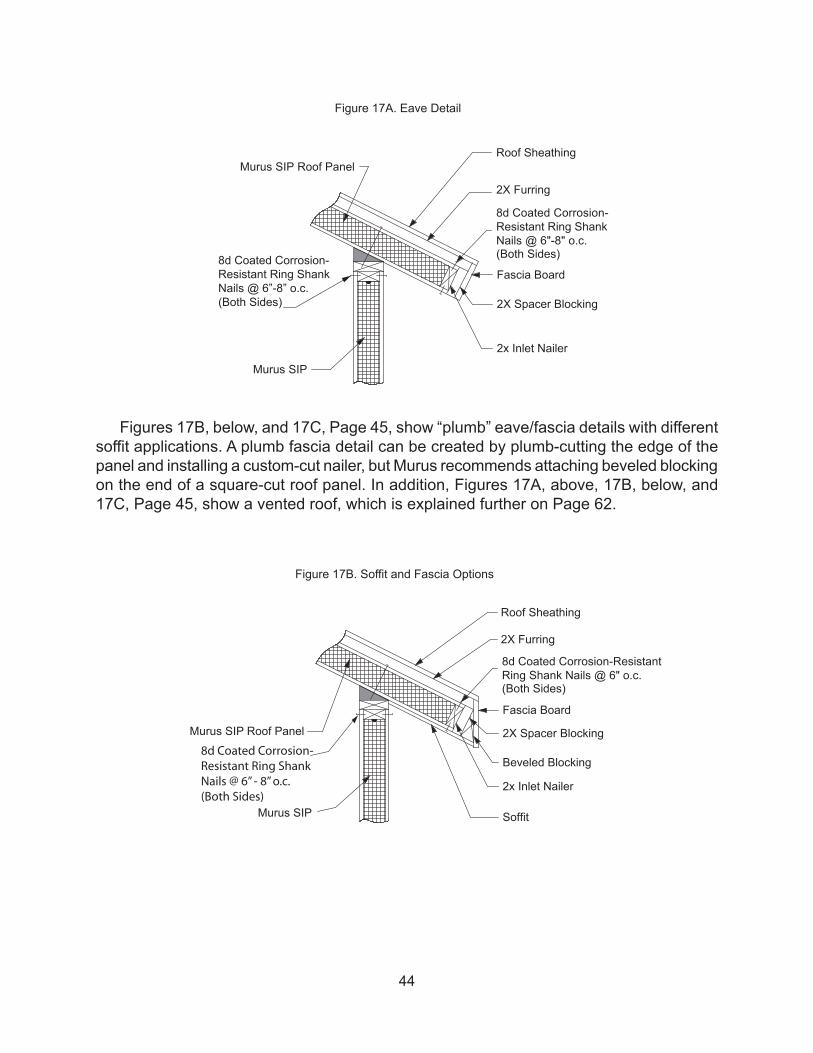
Eave Details
Figure 17A on Page 44 shows the typical squared eave construction detail where an inlet nailer is fully housed in the end of the panel, and nailed with 8d coated corrosion-resistant ring shank nails at 4” - 6” on center from the top and bottom sides.
Rafter
16d Coated Nails @ 6” o.c. Staggered or Offset
8d Coated Corrosion-Resistant Ring ShankNails @ 6” o.c. (Both Sides)
8d Coated Corrosion-Resistant Ring Shank Nails @ 6” o.c. (Both Sides)
2x Inlet Nailer
Murus SIP (Cut toFit Between Rafters)
Spray Foam Sealant
2x Inlet Nailer
Construction Adhesive2x Inlet Nailer
Spray Foam Sealant
Murus SIP
2x Top Plate
Figure 16C. Typical Rafter Bearing on Top Plate Detail
44
Figures 17B, below, and 17C, Page 45, show “plumb” eave/fascia details with different soffit applications. A plumb fascia detail can be created by plumb-cutting the edge of the panel and installing a custom-cut nailer, but Murus recommends attaching beveled blocking on the end of a square-cut roof panel. In addition, Figures 17A, above, 17B, below, and 17C, Page 45, show a vented roof, which is explained further on Page 62.
Murus SIP
Murus SIP Roof Panel
8d Coated Corrosion-Resistant Ring ShankNails @ 6"-8" o.c.(Both Sides)
2x Inlet Nailer
2X Spacer Blocking
Fascia Board
2X Furring
Roof Sheathing
8d Coated Corrosion-Resistant Ring ShankNails @ 6”-8” o.c.(Both Sides)
Murus SIP
Murus SIP Roof Panel
8d Coated Corrosion-ResistantRing Shank Nails @ 6" o.c. (Both Sides)
2x Inlet Nailer
2X Spacer Blocking
Fascia Board
2X Furring
Roof Sheathing
Beveled Blocking
Soffit
8d Coated Corrosion-Resistant Ring ShankNails @ 6” - 8” o.c.(Both Sides)
Figure 17A. Eave Detail
Figure 17B. Soffit and Fascia Options

45
Rake Details:
Figure 18, below, shows a typical rake construction detail with an inlet nailer fully housed in the end of the roof panel and fastened with 8d coated corrosion-resistant ring shank nails at 6” - 8” centers through both top and bottom skins. As with the inlet nailers in wall panels, the butt ends of roof panel inlet nailers must be offset from panel-to-panel joints.
Murus SIP
Murus SIP Roof Panel
8d Coated Corrosion-Resistant Ring Shank Nails @ 6"-8" o.c.(Both Sides)
2x Inlet Nailer
2X Spacer BlockingFascia Board
2X Furring
Roof Sheathing
Beveled Blocking
Soffit
2X Nailer
8d Coated Corrosion-Resistant Ring ShankNails @ 6”-8” o.c.(Both Sides)
Murus SIP
Murus SIP Roof Panel
8d Coated Corrosion-Resistant Ring Shank Nails @ 6"-8" o.c.(Both Sides)
2x Inlet Nailer
Fascia Board
2X Furring
Roof Sheathing
Figure 17C. Soffit and Fascia Options
Figure 18. Rake Detail

46
Roof Peak or Ridge Details:
Two typical ridge details are shown in Figures 19A and 19B, below. Figure 19A is most common when utilizing a ridge beam. Here the joining roof panels are simply mitered and sealed with liberal amounts of spray foam sealant as they are fastened to the ridge beam, with appropriately sized panel nails or screws (per Fastening Schedule, Page 14). Figure 19B illustrates an optional detail for use with a 12:12 pitch only.
Ridge Beam
Panel Fasteners perTable 2 on Page 14Spray Foam Sealant
Murus SIPRoof Panel
Ridge Beam
Panel Fasteners perTable 2 on Page 14
Spray Foam Sealant
Murus SIPRoof Panel
8d Coated Corrosion-Resistant Ring ShankNails @ 6"-8" o.c.
Figure 19A. Typical Roof Peak or Ridge Detail
Figure 19B. Optional Roof Peak or Ridge Detail for 12:12 Pitch

47
Installing Nailers In Rough Openings:
Rough opening details are similar for doors, windows, and skylights. The measurements for the position of the rough opening are taken from the panel drawings or the architectural drawings. After cutting and routing the openings and installing the panels, the openings are foamed with liberal amounts of spray foam sealant, and nailers installed as shown in Figure 20A, Page 48.
Figure 19C, below, illustrates two structural ridge details. These details are used in the absence of a ridge beam, or in conjunction with a ridge beam under certain spans and/or loading conditions.
The panels are mitered to the correct angle and routed to accept an inlet 2X nailer which is beveled to match the roof pitch. The nailers are to be fastened together, using coated corrosion-resistant ring shank nails and construction adhesive, to form a continuous member for the length of the ridge. This member creates the ridge and provides the panel connection. Spray foam sealant is applied between the nailer and the foam core of the panel as the panels are installed. The panels are then fastened to the 2X nailers with 8d coated corrosion-resistant ring shank nails at 4” - 6” on center from both sides.
Spray Foam SealantSpray Foam Sealant
Murus SIPRoof Panels
8d Coated Corrosion-Resistant Ring ShankNails @ 4"-6" o.c.(Both Sides)
(2) 2x Beveled Inlet NailerGlued & Nailed Together
Spray Foam SealantSpray Foam Sealant
Murus SIPRoof Panels
8d Coated Corrosion-Resistant Ring ShankNails @ 4"-6" o.c.(Both Sides)
(4) 2x Beveled Nailers Glued& Nailed Together
s
Figure 19C. Structural Ridge Details

48
The bottom (sill) and top (header) nailers (1) should be installed first. They should be cut 3” longer than the opening dimension so they will run 1½” past each side of the open-ing and allow the side (jack) nailers (2) to bear. Spray foam sealant should be applied between the nailers and the foam core. Once the nailers are fully set into the openings, the nailers are fastened with 8d coated corrosion-resistant ring shank nails at 6” - 8” on center from both sides.
11*
22*
11*
*1 = Install First; *2 = Install after all #1’s have been installed
2x Top Plate
16d Coated Nails @ 6” o.c.Staggered or Offset
Construction Adhesive
2x Inlet Nailer
8d Coated Corrosion-Resistant Ring Shank Nails6” - 8” o.c. (Both Sides)
Spray Foam Sealant
2x Inlet Nailer
Murus SIP
Electrical Chase(Optional)
8d Coated Corrosion-Resistant Ring Shank Nails4” - 6” o.c. (Both Sides)
Spray Foam Sealant
2x Inlet Nailer
Figure 20A. Rough Opening Details

49
Installing Headers In Rough Openings:
Headers may be required to support and transfer loads over openings in SIP walls. Unlike most conventional framing, most panel headers are positioned at the top of the wall and sit fully on at least two studs (posts or jack studs) on each end of the header. While each installation may require some variation on an installation procedure, Murus recommends cutting the 2X inlet posts to the correct length and connecting them together with construction adhesive and nails or screws. Once the wall panel next to the ‘headered’ opening is installed and braced, the 2X inlet post can be installed in the panel with liberal amounts of spray foam and 8d coated corrosion-resistant ring shank nails. At this point, if there is a piece of wall panel below the opening, it can be installed or at least set into position. If there is a piece of wall panel above the opening, it should also be set into the opening, but left loose; it will be slid up into its position once the header is installed. Next, position the wall panel and posts on the opposite side of the opening. Once braced, the header can be installed so it sits on the bearing surfaces of the posts. If there are pieces of wall panels above and/or below the opening, these can be attached to the posts and the header at this time and the header and sill inlet nailers can be installed. If there is a top plate on the wall assembly, it should run continuous over the header and onto the panels on either side. Once the top plate is installed, 7/16” OSB can be attached to the header to match the surface planes of the SIP walls.

50
Hole Drilled to MatchElectrical Chase
8d Coated Corrosion-Resistant Ring Shank Nails4” - 6” o.c. (Both Sides)
16d Coated Nails @ 6” o.c.Staggered or Offset
2x Top Plate
Construction Adhesive
Header (Engineeredor 2x Material)
Murus SIP
Spray Foam Sealant
2x Inlet Posts
Murus SIP
8d Coated Corrosion-Resistant Ring Shank Nails 6”- 8” o.c. (Both Sides)
Electrical Chase
Spray Foam Sealant
3” or 3 1/2” Coated Screws @ 6” o.c.Staggered or Offset
2x Inlet Nailer
8d Coated Corrosion-Resistant Ring Shank Nails 4” - 6” o.c. (Both Sides)
Figure 20B. Rough Opening Detail with Support Header

51
Installing Doors, Windows, and Skylights:
Always install door, window, and skylight units plumb, square, and according to the manufacturer’s recommendations. When installing flange-mounted units, pay close attention to the nailing flanges. Flanges that are bent or warped or are not straight and perpendicular to the unit may cause many problems later with trim and finishing details.
Before you shim and nail the unit to the 2X nailer in the rough opening, you should first check to ensure that the unit’s jambs are flush or at an equal distance to the interior side of the wall. If inconsistencies are found, it is recommended to adjust the unit to remove the inconsistencies. This can be accomplished by first securing the top, bottom, side, or corner of the unit that is correct, then adjust the area(s) in or out as required, then shim the unit and secure in place. Check to ensure there is a gap between the unit and the rough opening to allow for proper sealing of the unit. Note: All sides of the unit must be sealed.
NOTE: Once the unit is secured and before setting the nails, check the operation of the unit for smooth and free movement.
After installation of the unit and before applying the interior trim, the gaps around the rough opening are to be sealed with minimally-expanding spray foam sealant. The spray foam should be applied in multiple small applications until the cavity is filled.
IMPORTANT: Allow each application to cure (12 - 24 hours) before applying the next layer.
Correct spray foaming procedures will help prevent the possibility of pinching and/or bowing of the jambs caused by excessive pressure that may be created by the expansion of the foam during the curing process. Overfilling may cause the unit to bind or stick during operation. If this occurs, simply relieve the pressure by cutting away the foam and reapplying correctly. The unit is now ready for trim and finishing. For more information see Sealing with Spray Foam on Page 24.
52
Murus recommends that all wiring conform to applicable local, state, and national codes.
With Murus SIPs, electrical circuits can easily be run through the exterior walls during or after panel installation. While wiring the interior stud walls is the same as in conventional construction, the optional electrical chase cut into the foam core of the Murus EPS SIP makes wiring the exterior panel wall fairly simple.
A little forethought toward the design of the electrical system can save a lot of time and aggravation. Generally all, or most all, wiring can be accomplished after panel installation, provided that access to the electrical chase is established during installation. It is recommended that an electrician be on site during the panel installation to ensure that there is adequate access for the required wiring.
The 1½” diameter electrical chase runs horizontally at a predetermined height in the wall panels. Access to the electrical chase can be accomplished through exterior corners, exterior door openings, or anywhere the foam core is exposed. Instead of covering the chase in the panel with the 2X inlet nailer, the 2X nailer can be cut short or be left out until after the wiring is complete. This allows easy access to the chase(s) for pulling or pushing electrical wiring.
IMPORTANT: In either case the nailer must be replaced as soon as the electrical wiring is complete.
Where an interior partition wall meets an exterior panel wall is also a good location to gain access to the electrical chase. Where posts or bearing members are let into the panel, a 1½” diameter hole must be drilled in the wood member in line with the chase to ensure continuous access through the electrical chase.
Generally, electrical circuits run from the receptacle boxes through the chase and lead back to the electrical panel through the floor framing and/or interior partition walls. Wires can be led through the horizontal panel chases, vertical panel seams, behind inlet nailers, interior partition walls, floor framing, exposed/unframed corner connections, and door rough openings. For slab construction, access is made through a conduit run to the exterior sill or interior partition walls.
Accessing Wiring Receptacles:
The optional electrical chase in the panels can be used to run wires to both interior and exterior receptacles. The chase will be at a constant predetermined height along each wall (refer to panel drawings or Murus Sales Order). Determine the location of, and cut all
WIR ING

53
receptacle boxes before running wires (this will help eliminate the possibility of cutting the wire). Locate the top or bottom of the receptacle box at the chase height. Using a keyhole saw, router, jig saw, or spiral saw, cut through the OSB to the chase depth (see Figure 21, below). Remove the OSB cutout and then remove foam to the required depth for the box. Run the wires from box cut-out to box cut-out, pull wires through the box and secure the box to the OSB. When running wires it is recommended to run from box to box as opposed to pulling loops. At interior wall locations, be sure to leave enough wire coiled to reach the next in-line receptacle (see Figure 22, Page 54). When using interior walls it is recommended to break rooms up into circuits (see Figure 23, Page 54).
NOTE: Be sure to seal around all receptacle boxes with spray foam sealant after electrical wiring has been completed.
Murus SIP
2x Inlet Nailer
Spray Foam Sealant
ElectricalChase
V-Groove (Field-CutSo Wire Lays Into Foam Core)
Hole DrilledThroughSubfloorFor Wire
SubfloorSheathing
RIim Board
Sill Seal w/Insect Shield
Foundation Wall
Floor Joist
Electrical Box
Cut–Out For Electrical Box (Above or Below Chase)
Figure 21. Typical Receptacle Box Installation

54
Murus SIP
ElectricalChase
SubfloorSheathing
Cut-Out for Electrical Box(ABove or Below Chase)
Electrical Box
Floor Joist
Hole Through Stud andInto Panel/Electrical Chase
Run Wire Over Door orUnder Subfloor at DoorLocationsTo Electrical Panel
Figure 22. Typical Interior Wall Receptacle Box Wiring
Figure 23. Typical Electrical Circuit Layout

55
SubfloorSheathing
Electrical Wire(Behind Inlet Nailer)
Electrical Chase
Murus SIP
8d Coated Corrosion-Resistant Ring Shank Nails6” - 8” o.c. (Both Sides)
Spray Foam Sealant
16d Coated Nails @ 6” o.c.Staggered or Offset
Field-Drilled HoleThrough Foam CoreTo Switch Location
2x Top Plate
Switch Box
Construction Adhesive
2x Inlet Nailer
2x Inlet Nailer
Figure 24. Typical Electric Switch Box Installation

56
Accessing Light Switches:
For exterior wall switch box locations, it is common practice to locate the boxes next to a door opening (see Figure 24, Page 55). Access to boxes is accomplished through the door rough opening. After the foam is routed out and before the inlet nailer is installed, locate and cut the hole for the box (as explained in previous paragraph). From the rough opening of the door, drill a hole large enough to fit the electrical wires to the switch, horizontally to the hole cut for the electrical box. Using a utility knife or other tool, create a groove in the foam core where the inlet will be installed, making the groove large enough to accept the wires. This will ensure the 2X inlet will sit flush with the OSB skins when installed. Run the wires from the electrical chase up the groove in the foam and through the horizontal hole to the box location before installing the 2X inlet.
Establishing Wiring Access to the Second and Third Floor:
To run wiring vertically up to second floor areas, outdoor lighting, etc., the best method is to use the conventional framing of interior partition walls which intersect the exterior SIP walls.
Wiring in Roof Panels:
Roof panels typically do not include a horizontal electrical chase. Instead of using a chase on roof panels, wiring is run between the seams of the panels during installation to bring power to overhead ceiling lights or fans (see Figure 25, Page 57).

57
Murus SIP
Panel Joint Sealed WithSpray Foam Sealant
Wire to Interior LightPurlin
2x Bevel Blocking
Hole Drilled ThroughInlet Nailer and BevelBlocking for Wire
Hole Drilled ThroughFoam Core
Wire From Switch
Murus SIP8d Coated Corrosion-Resistant Ring Shank Nails6” - 8” o.c. (Both Sides)
2x Inlet Nailer
V-Groove Cut in Foamfor Electrical Wire
Electrical Wire
Electrical Chase
SubfloorSheathing
Hole Drilled ThroughSubfloor for Wire
16d Coated Nails @ 6” o.c.Staggered or Offset
Figure 25. Typical Wire Detail At Roof Panels

58
Wiring Around Doors and Windows:
Refer to Figures 26, below, and Figure 27, Page 59, for details.
2x Top Plate16d Coated Nails @ 6” o.c.Staggered or Offset
Construction Adhesive
2x Inlet Nailer8d Coated Corrosion-Resistant Ring Shank Nails6” - 8” o.c. (Both Sides)
Murus SIP
Spray Foam Sealant
2x Inlet Nailer
Electrical Chase
Electrical Wire
Hole Drilled ThroughInlet Nailer and Subfloor
SubfloorSheathing
Figure 26. Typical Wiring Around Doors

59
Groove Cut inFoam Core toAccommodateElectrical Wire
2x Top Plate16d Coated Nails @ 6” o.c.Staggered or Offset
Construction Adhesive2x Inlet Nailer
8d Coated Corrosion-Resistant Ring Shank Nails6” - 8” o.c. (Both Sides)
Murus SIP
Spray Foam Sealant
2x Inlet Nailer
ElectricalChase
Electrical Wire
Figure 27. Typical Wiring Around Windows

60
The following section provides some pertinent information about finishing a Murus SIP building. Obviously, not every situation can be covered so please consult with Murus if you have additional questions about finishing details.
Continuous Nailing Surface:
A significant advantage of SIP construction is that it provides a continuous nailing surface over the entire interior and exterior wall and roof surfaces. This makes it more convenient to hang drywall and kitchen cabinets, install interior partitions, roofing, siding, and trim.
Vapor Barriers:
With Murus SIPs, interior vapor barriers (such as 6 mil. poly film) are not necessary unless required by local building codes. Unlike conventional ‘stick frame’ construction, properly installed and sealed Murus SIPs do not have wall cavities where water vapor can collect and condense.
House Wraps:
A house wrap or building felt is to be applied to the exterior of the wall panels prior to installation of exterior finish materials. Selection of the material used should be based on the siding and/or exterior finish material being used, the recommendation of the siding manufacturer, and sound building practices. See Siding and Exterior Finishes on Page 62 for more information.
Air Infiltration:
It is Murus’s intent and recommendation to eliminate as much air infiltration as possible through the use of Murus SIPs, the liberal use of spray foam sealant, construction adhesives, mastics, and caulk. Contrary to prior practices of “allowing a building to breathe”, Murus recommends making it as “tight” as possible and installing an air-to-air exchanger.
Air Exchangers:
An air-to-air exchanger is a mechanical device that introduces fresh outside air and tempers and/or dehumidifies it with outgoing stale interior air, recovering much of the heat or energy from the interior air. There are two basic types of exchanges, the Heat Recovery Ventilator (HRV), and the Energy Recovery Ventilator (ERV). HRV units are best suited for colder northern climates because they transfer the heat energy from the warm moist air being exhausted to the cooler dry air being brought in. The transfer of energy pre-heats the incoming air and helps reduce heating costs. ERV units are best suited for warmer southern climates because they reduce the humidity of the incoming air. The reduction of
FINISHING DETAILS

61
humidity helps reduce cooling costs. Consult with your mechanical contractor for what is best for your project.
IMPORTANT: An air-to-air exchanger is required to control indoor air pollutants, to maintain a healthy quality of air, and to remove excessive humidity that can cause serious harm to SIPs and to other parts of your home. Failure to install and operate a properly sized air exchanger can lead to excessive interior moisture levels, which can damage building components, cause wood decay, and propagate molds and mildews which contribute to poor indoor air quality, and may void the warranty on the panels. Please contact Murus or a qualified mechanical contractor for further information on air-to-air exchangers.
Drywall and Other Interior Finishes:
The most common interior wall surface is drywall. Murus recommends that drywall be applied directly to the panel surface perpendicular to the panel joints, using the drywall manufacturer’s recommended fastening schedule and finishing details. This orientation will give the most strength to the drywall joints. If drywall must be installed parallel with the panel seams, be sure to offset the drywall seams from the panel seams by a minimum of 12”. Standard installation practices can be used regarding piecing, joining, and finishing.
Other materials used for the interior finish, such as tongue-and-groove boards, paneling, etc., may be applied using accepted practices.
Roofing:
Murus recommends the use of a lightweight felt product under the finished roofing materials. The product allows moisture to pass through its membrane while blocking the flow of rain water and/or condensed moisture. The covering also offers temporary protection of the roof surfaces and does not have to be removed before applying shingles. Finished roofing material can include heavyweight asphalt or composite shingles, metal, wood, or slate. NOTE: Always install roofing materials according to accepted methods and in accordance with the manufacturer’s recommendations.
Shingles:
Not all shingle manufacturers warrant shingles applied directly over an insulated deck or SIPs. Depending on your choice of manufacturer, an additional ventilated space may be required for warranty qualification. An additional ventilated space is recommended and is always more desirable. Venting may also increase the life of the shingle by lowering the shingle’s temperature.

62
Venting the Roof:
The preferred and recommended method for roofing installation is on an elevated, ventilated surface (see Figure 28, below). Furring strips or strapping are screwed vertically over a layer of roofing felt to the exterior surface of the roof panel on 16” - 24”centers. A layer of sheathing material is applied on the strapping as the nail base for the shingles. (For metal roof applications, an additional layer of strapping, installed horizontally, can be used in lieu of the sheathing.) This system requires both eave and ridge vents to vent the cavity and prevent condensation and heat buildup. For eave, soffit, and fascia details, see Figure 16A through 16C on Pages 42 and 43.
NOTE: This system is designed to provide a continuous, uninterrupted air space from the soffit to the ridge between the roof panel and roof surface to help reduce the roof system temperature (see WARNING Note on page 6).
NOTE: This system may help reduce the chance of shingle lifting, ridging, and definition lines caused by frost and/or the presence of moisture.
Siding and Exterior Finishes:
Virtually any type of siding may be applied to the exterior surface of a wall SIP. Some common materials include a variety of vinyl siding, aluminum siding, cementitious, and wood sidings to include clapboard, shiplap, board and batten, and shingles.
NOTE: All wood sidings are to be kiln dried. Green or air-dried sidings must be furred away from the panel surface, with a layer of house wrap or felt paper installed. Always follow acceptable building practices and/or manufacturer’s installation instructions.
Roofing Felt
Panel Fastener
Roof Sheathing(Cut Back for Vent)
2x Furring (Screwed to Panel)
Murus SIP
Corrosion-ResistantCommon Nails
Ridge Purlin
Figure 28. Vented Roof System

63
Sidings and trims are to be installed as a weatherproof covering to protect the SIPS from moisture and/or water damage. Exterior finishes should always be installed in accordance with the manufacturer’s recommended installation instructions and/or acceptable building practices. When installing exterior finishes, it is required to first apply a layer of house wrap or felt paper over the SIPs to protect them from moisture and/or water damage. The use of flashing and waterproof membranes are recommended in water leak-prone areas for added protection.
NOTE: Slight inaccuracies in installation and improper sealing techniques, compounded by weathering of the exterior finishes, will eventually result in water leaks. Once a leak has developed, it generally does not become apparent until serious damage to the SIPs has occurred. Therefore, it is strongly recommended that inspections be done at regular intervals, and preventive maintenance be carried out on the exterior finishes to prevent any such damage to the SIPs.
Masonry Finishes:
Masonry and fiber-reinforced stuccos can also be used if a ventilated air space is provided. Ventilated air spaces allow these materials to breathe and expand and contract separately from the panel surface. Follow accepted building practices and the finish material manufacturer’s recommendations for ventilation and proper installation.
Masonry materials such as brick veneer must not come in direct contact with the SIP. A vented air space between the veneer and SIPs, and weep holes in the masonry must be provided (see Figure 29, Page 64).

64
Interior Finish: Trim, Cabinets, Etc.:
Interior and exterior trim details are similar for SIP and conventional construction. The primary difference is that in SIP construction there is a continuous nailbase on all wall and/or ceiling surfaces. This facilitates the attachment of cabinets, trim, picture frames, and other fixtures.
Murus SIP
House Wrap or Felt Paper
Brick Veneer
Air Space (Minimum 3/4”)
Subfloor Sheathing
Floor Joist
Anchor Bolt
Construction Adhesive
Masonry Foundation
Sill Seal w/Insect Shield
2x Pressure-TreatedSill Plate
2x Inlet Nailer
3” Coated Screws @ 6“ o.c. Staggered or Offset
Spray Foam Sealant
ProvideWeep Holes
Figure 29. Veneer Detail

65
MURUS STRUCTURAL INSULATING PANEL TECHNICAL GLOSSARY
2X Plates and Nailers Nominal dimensional lumber (usually 2” x 4”) used to frame cor-ners, rough openings, eaves, rakes, sill plates, etc.
Axial Load A force of load acting in the direction of the object’s axis.
Beam A component or building member used to transfer the loads of a floor or roof system to a vertical structural system such as a bearing wall or a set of posts.
Bearing Surface The part of the material able to support a structural load.
Concrete Masonry Unit Analogous to a cinder block or a formed modular unit made of masonry used with mortar and other reinforcement to build walls and foundation sys-tems.
Class “1” Foam An ASTM fire rating for foam core material. The highest rating possible for combustible materials.
Crane A portable piece of machinery, usually attached to a truck with hydraulic controls, that is used to pick up and move heavy loads with cables attached to an extendable boom.
Dead Load The weight of the structural member and the weight of any permanent objects that act on that member.
Eave An overhang of the wall at the lower end of the roof.
Electrical Chase A 1-½” horizontal round cut-out in the Murus EPS or XPS panel for the purpose of running electrical wire.
ERV Energy Recovery Ventilator. Mechanical air handling equipment.
EPS Expanded Polystyrene. Closed cell rigid foam such as Styrofoam (TM).
Foam The rigid core of an insulating panel.
Flexure A structural term analogous to bending that describes the action on a beam or structural system as a result of a transverse uniform or point load.
Heat Build-up Increase in temperature due to the addition of heat to a space in greater quantities than can be released from the space.
HRV Heat Recovery Ventilator. Mechanical air handling equipment.
ICC International Code Council A membership association which develops the codes used to construct residential and commercial buildings, including homes and schools.
Level Horizontal. Perpendicular to vertical. Used as a building term to mean a member or surface is horizontally positioned.
Live Load A moving load such as snow or wind that acts on a structure.
APPENDIX A

66
Mastic An adhesive that is used in place of spray foam sealant to seal a panel seam from air and moisture passing through.
NEOPOR® Charcoal-infused EPS foam manufactured by BASF. NEOPOR has a higher R-value per inch of thickness than regular EPS foam, but lower than PUR foam.
Non-Expanding Foam A liquid urethane foam dispensed from a hand-held canister used to fill and seal expansion joints, gaps around doors, windows, and skylights, and to create a bond between panel-to-panel and panel-to-wood surfaces.
O.C. On center.
OSB Oriented Strand Board. OSB consists of short wood strands that are layered and oriented perpendicular to each other, then bonded with adhesives to maximum strength, stiffness, and stability. Used as the interior and/or exterior sheathing surface of Murus SIPs.
OSHA Occupational Safety and Health Administration.
Panel Drawings A portion of the construction documents that show elevations, plans, and all necessary details that describe the building process for SIP construction.
Panel Fastener A coated corrosion-resistant nail or screw specially designed to fasten panels to a frame or to other panels.
Panel Router A hand-held power tool equipped with special bits to remove the foam core of SIPs for the purpose of inserting splines, inlets, and posts.
Plumb Vertical. Perpendicular to level. Used as a building term to mean that a surface or member is vertically positioned.
Purlin A structural roof member oriented perpendicular to the pitch of the roof.
Racking A structural term to describe an in-plane shear action on a frame or dia-phragm.
Rafter A structural roof member oriented along the pitch of the roof.
Rake The overhang at the gable end of the roof.
Riser Wood or other material on which SIPs and other building materials are stacked. Ris-ers create a space to allow a forklift, crane, etc. to pick up or set down materials. Risers also prevent these materials from coming in direct contact with the ground surface.
R-Value A measure of the capacity of a material, such as insulation, to resist heat flow, with increasing values indicating a greater capacity.

67
Service Temperature The temperature to which a building component will be subject during and after installation.
Sill A structural member used to cap a foundation or wall panels such as the pressure treated sill plate. Also used to reference the bottom of a window or window rough opening.
SIP(s) Structural Insulating Panel(s)
SIP Tape A product that is applied to the seam of a SIP to seal from air or moisture passing through.
Skin The outer rigid surface or material of a structural insulating panel.
Spline Usually a wood member used to join two panels together.
Spray Foam A urethane foam available in aerosol cans with trigger applicators, used to seal panel-to-panel and panel-to wood connections, as well as to fill any gaps in the EPS or XPS foam made as a result of routing or cutting.
Sticker See Riser.
Stress-Skin Panel A building product that uses strong, stiff exterior facing material around a less dense core to resist axial, flexural and racking loads. Includes structural insulating panels.
Truss A system of structural members oriented efficiently to carry building loads over open spans.
XPS Extruded Polystyrene. Closed cell rigid foam.

68
NOTES

NOTES

The Murus Company, Inc.PO Box 220 ▪ 3234 Route 549
Mansfield, PA 16933(800) 626-8787 ▪ (570) 549-2100
Fax: (570) 549-2101E-mail: [email protected] ▪ www.murus.com