Epoxy resin - High performance for use in cracked and ... · PDF fileEpoxy resin - High...
12
82 Epoxy resin - High performance for use in cracked and non-cracked concrete INSTALLATION * APPLICATION Steel profiles Fixing machinery (resistant to vibration) Storage tanks, pipes Signs Guard rails Electrical insulated fixings Anchor mechanical properties Technical data ETA Option 1- 10/0309 European Technical Assessment ETA ETA EPCON C8 STANDARD EMBEDMENT - Zinc coated & stainless steel studs Anchor size M8 M10 M12 M16 M20 M24 M30 MAXIMA stud - zinc coated steel version fuk (N/mm 2 ) Min. tensile strength 600 600 600 600 520 520 520 fyk (N/mm 2 ) Yield strength 420 420 420 420 420 420 420 M 0 rk,s (Nm) Characteristic bending moment 22 45 79 200 301 520 1052 M (Nm) Recommended bending moment 11,0 22,5 39,5 100 150 160 525 MAXIMA stud - stainless steel A4 version fuk (N/mm 2 ) Min. tensile strength 700 700 700 700 700 700 - fyk (N/mm 2 ) Yield strength 350 350 350 350 350 350 - M 0 rk,s (Nm) Characteristic bending moment 26 52 92 233 454 786 - M (Nm) Recommended bending moment 12 23 42 122 206 357 - As (mm 2 ) Stressed cross-section 36,6 58 84,3 157 227 326,9 - Wel (mm 3 ) Elastic section modulus 31,2 62,3 109,2 277,5 482,4 833,7 - Anchor size Min. anchor depth Max. thick. of part to be fixed Min. thick. of base material Thread diameter Drilling depth Drilling diameter Clearance diameter Total anchor length Tighten torque Code* MAXIMA stud (mm) (mm) (mm) (mm) (mm) (mm) (mm) (mm) (Nm) zinc coated st. stainless steel A4 hef tfix hmin d hO dO df L Tinst M8X110 80 15 110 8 80 10 9 110 10 050950 052400 M10X130 90 20 120 10 90 12 12 130 20 050960 052410 M12X160 110 25 140 12 110 14 14 160 30 050970 052420 M16X190 125 35 160 16 125 18 18 190 60 050980 052440 M20X260 170 65 220 20 170 25 22 260 120 655220 052450 M24X300 210 63 265 24 210 28 26 300 200 655240 052470 M30X380 280 70 350 30 280 35 33 380 400 050940 - EPCON C8 Epoxy resin, dual component cartridge 450 ml 055887 EPCON C8 Epoxy resin, dual component cartridge 900 ml 055829 * These are Maxima studs, for standard studs (zinc coated or stainless steel versions) see catalogue. 1/12 100% 20 40 60 80 100 120 140 80% 60% 40% 20% 0% Temperature of the fixing(°C) Effect of temperature on the resistance d0 hmin L d hef = h0 df tfix Tinst x2 x2 x2 Setting time Chemical resistance of the SPIT EPCON C8 resin Ambient temperature Max. time for installation (min) Waiting time for 45 % load (h) Curing time (h) 40°C 5 3 6 30°C 8 5 8 20°C 14 6 12 10°C 20 12 23 5°C 26 15 26 Chemical substances Concentration (%) Resistance Sulfuric acid 10 (o) Hydrochloric acid 10 (o) Nitric acid 10 (o) Acetic acid 10 (o) Ammonium hydroxide 10 (o) Sodium Hypochlorite 5 (o) Sodium hydroxide 50 (o) Acetone (-) Chemical substances Concentration (%) Resistance Toluene (o) Ethanol (o) Methyl-ethyl-ketone (MEK) (-) Methanol (-) Demineralized water (+) Sea water 100 (+) Engine Petrol 100 (+) Motor oil 100 (+) Resistant (+): the samples in contact with the substances did not show any Screwible damage such as cracks, attacked surfaces, burst corners nor large swelling. Sensitive (o): use with care regarding exposure of the field of usage, precautions to be taken. The samples in contact with the substance slightly attacked the material. *Premium cleaning : - 2 blowing with compressed air - 2 brushing with brushed fitted on a drilling machine - 2 blowing with compressed air STAINLESS STEEL MATERIAL Zinc coated steel version : Stud M8-M16 : Steel cold form steel NF A35-053 Stud M20-M30 : 11 SMnPb37 - NFA 35-561 Nut : Steel grade 6 or 8 NF EN 20898-2 Washer : Steel DIN 513 Protection : zinc coated 5 μm min. NF E25-009 Stainless steel version : Stud : A4-70 as per ISO 3506-1 Nut : Stainless steel A4-80, NF EN 10088-3 Washer : Stainless steel A4, NF EN 20898-2
Transcript of Epoxy resin - High performance for use in cracked and ... · PDF fileEpoxy resin - High...

82
Epoxy resin - High performancefor use in cracked and non-cracked concrete
INSTALLATION*
APPLICATION Steel profiles Fixing machinery (resistant to vibration) Storage tanks, pipes Signs Guard rails Electrical insulated fixings
Anchor mechanical properties
Technical data
ETA Option 1- 10/0309
European Technical Assessment
ETAETA
EPCON C8STANDARD EMBEDMENT - Zinc coated & stainless steel studs
Anchor size M8 M10 M12 M16 M20 M24 M30MAXIMA stud - zinc coated steel versionfuk (N/mm2) Min. tensile strength 600 600 600 600 520 520 520fyk (N/mm2) Yield strength 420 420 420 420 420 420 420M0
rk,s (Nm) Characteristic bending moment 22 45 79 200 301 520 1052M (Nm) Recommended bending moment 11,0 22,5 39,5 100 150 160 525MAXIMA stud - stainless steel A4 versionfuk (N/mm2) Min. tensile strength 700 700 700 700 700 700 -fyk (N/mm2) Yield strength 350 350 350 350 350 350 -M0
rk,s (Nm) Characteristic bending moment 26 52 92 233 454 786 -M (Nm) Recommended bending moment 12 23 42 122 206 357 -As (mm2) Stressed cross-section 36,6 58 84,3 157 227 326,9 -Wel (mm3) Elastic section modulus 31,2 62,3 109,2 277,5 482,4 833,7 -
Anchor size Min. anchor depth
Max. thick. of part to be fixed
Min. thick. of base material
Threaddiameter
Drilling depth
Drilling diameter
Clearance diameter
Total anchor length
Tighten torque
Code*MAXIMA stud
(mm) (mm) (mm) (mm) (mm) (mm) (mm) (mm) (Nm) zinc coated st.
stainless steel A4hef tfix hmin d hO dO df L Tinst
M8X110 80 15 110 8 80 10 9 110 10 050950 052400
M10X130 90 20 120 10 90 12 12 130 20 050960 052410
M12X160 110 25 140 12 110 14 14 160 30 050970 052420
M16X190 125 35 160 16 125 18 18 190 60 050980 052440
M20X260 170 65 220 20 170 25 22 260 120 655220 052450
M24X300 210 63 265 24 210 28 26 300 200 655240 052470
M30X380 280 70 350 30 280 35 33 380 400 050940 -
EPCON C8 Epoxy resin, dual component cartridge 450 ml 055887
EPCON C8 Epoxy resin, dual component cartridge 900 ml 055829
* These are Maxima studs, for standard studs (zinc coated or stainless steel versions) see catalogue.
1/12
100%
20 40 60 80 100 120 140
80%
60%
40%
20%
0%
Temperature of the fixing(°C)Effe
ct o
f te
mpe
ratu
re o
n th
e re
sist
ance
d0
hmin
L
d
hef = h0
df
tfix
Tinst
x2
x2
x2
Setting time
Chemical resistance of the SPIT EPCON C8 resin
Ambient temperature Max. time for installation
(min)
Waiting time for 45 % load
(h)
Curing time
(h)40°C 5 3 630°C 8 5 820°C 14 6 1210°C 20 12 235°C 26 15 26
Chemical substances Concentration (%)
Resistance
Sulfuric acid 10 (o)Hydrochloric acid 10 (o)Nitric acid 10 (o)Acetic acid 10 (o)Ammonium hydroxide 10 (o)Sodium Hypochlorite 5 (o)Sodium hydroxide 50 (o)Acetone (-)
Chemical substances Concentration (%)
Resistance
Toluene (o)Ethanol (o)Methyl-ethyl-ketone (MEK) (-)Methanol (-)Demineralized water (+)Sea water 100 (+)Engine Petrol 100 (+)Motor oil 100 (+)
Resistant (+): the samples in contact with the substances did not show any Screwible damage such as cracks, attacked surfaces, burst corners nor large swelling. Sensitive (o): use with care regarding exposure of the field of usage, precautions to be taken. The samples in contact with the substance slightly attacked the material.
*Premium cleaning :- 2 blowing with compressed air- 2 brushing with brushed fitted on a drilling machine- 2 blowing with compressed air
STAINLESSSTEEL
MATERIAL
Zinc coated steel version : Stud M8-M16 : Steel cold form steel NF A35-053 Stud M20-M30 : 11 SMnPb37 - NFA 35-561 Nut : Steel grade 6 or 8 NF EN 20898-2 Washer : Steel DIN 513 Protection : zinc coated 5 μm min. NF E25-009
Stainless steel version : Stud : A4-70 as per ISO 3506-1 Nut : Stainless steel A4-80, NF EN 10088-3 Washer : Stainless steel A4, NF EN 20898-2

83
Ultimate (NRu,m, VRu,m) and characteristic loads (NRk, VRk) in kN
Mean Ultimate loads are derived from test results in admissible service conditions, and characteristic loads are statistically determined.
TENSILE SHEAR
Design loads (NRd, VRd) for one anchor without edge or spacing influence in kN
TENSILE SHEAR
Recommended loads (Nrec, Vrec) for one anchor without edge or spacing influence in kN
TENSILE SHEAR
The loads specified on this page allow judging the product’s performances, but cannot be used for the designing.The data given in the pages “CC method” have to be applied (3/10 to 10/10).
Number of sealings per cartridge
EPCON C8STANDARD EMBEDMENT - Zinc coated & stainless steel studs
Anchor size M8 M10 M12 M16 M20 M24 M30Non-cracked concrete
hef 80 90 110 125 170 210 280
NRu,m 39,4 55,5 81,2 115,0 183,5 257,7 403,8
NRk 32,1 45,2 66,2 93,8 149,8 211,4 330,5
Cracked concrete
hef 80 90 110 125 170 210 280
NRu,m 27,0 37,7 55,1 82,5 139,4 205,4 340,4
NRk 20,8 29,1 42,3 63,6 107,3 157,9 261,3
2/12
*Derived from test results
(stud grade 10.9)Mc
NRk *NRd = Ms
VRk *VRd =
M F
NRk *Nrec = M F
VRk *Vrec =*Derived from test results
(stud grade 10.9)
Anchor size M8 M10 M12 M16 M20 M24 M30Drilling diameter (mm) 10 12 14 18 25 28 35
Drilling depth (mm) 80 90 110 125 170 210 280
Number of sealings per cartridge
EPCON C8 450 ml 166 121 83 56 12 11 5
EPCON C8 900 ml 331 241 167 112 25 22 10
Anchor size M8 M10 M12 M16 M20 M24 M30VRu,m 15,9 22,75 32,8 56,2 73,6 115,0 177,7
VRk 11,0 18,9 25,3 46,8 59,02 95,8 135,9
Anchor size M8 M10 M12 M16 M20 M24 M30Non-cracked concrete
hef 80 90 110 125 170 210 280
NRd 17,8 25,1 36,8 52,1 83,2 117,4 183,6
Cracked concrete
hef 80 90 110 125 170 210 280
NRd 11,6 16,1 23,5 35,3 59,6 87,7 145,1
Mc = 1,8
Anchor size M8 M10 M12 M16 M20 M24 M30VRd 7,7 13,2 17,7 32,7 39,3 63,9 90,6
Ms = 1,43 for M8 to M16 and Ms = 1,5 for M20 to M30
Anchor size M8 M10 M12 M16 M20 M24 M30Vrec 5,5 9,4 12,6 23,4 28,1 45,6 64,7
F= 1,4 ; Ms = 1,43 for M8 to M16 and Ms = 1,5 for M20 to M30
Anchor size M8 M10 M12 M16 M20 M24 M30Non-cracked concrete
hef 80 90 110 125 170 210 280
Nrec 12,7 17,9 26,3 37,2 59,4 83,8 131,1
Cracked concrete
hef 80 90 110 125 170 210 280
Nrec 8,3 11,5 16,7 25,2 42,5 62,6 103,6
Mc = 1,8

84
SPIT CC Method (values issued from ETA)TENSILE in kN SHEAR in kN
¬ Pull-out resistance
for dry and wet concrete (1)N
¬ Concrete cone resistance
for dry and wet concrete (1)
N
¬ Pryout failureV
¬ Steel resistance
N
¬ Concrete edge resistance V
fb INFLUENCE OF CONCRETE
¬ Steel resistanceV
N + V 1,2
f,V INFLUENCE OF SHEAR LOADING DIRECTION
β
V
90˚
180˚ 0˚
c
90°
≤ β ≤
180° 60°≤ β ≤90°
0°≤ β ≤60°
N0Rd,p Design pull-out resistance
Anchor size M8 M10 M12 M16 M20 M24 M30hef 80 90 110 125 170 210 280
Non-cracked concrete 17,9 25,1 36,9 52,4 83,1 114,4 190,6
Cracked concrete 10,6 14,9 20,7 29,7 50,4 74,8 102,6
Mc = 1,8
Concrete class fbC25/30 1,02
C30/40 1,08
C40/60 1,10
C50/60 1,12
Angle [°] f,V0 to 55 1
60 1,1
70 1,2
80 1,5
90 to 180 2
NRd,p = N0Rd,p . fb
NRd,c = N0Rd,c . fb . s . c,N
VRd,c = V0Rd,c . fb . fV . S-C,V
VRd,cp = V0Rd,cp . fb . s . c,N
EPCON C8STANDARD EMBEDMENT - Zinc coated & stainless steel studs 3/12
N0Rd,c Design cone resistance
Anchor size M8 M10 M12 M16 M20 M24 M30hef 80 90 110 125 170 210 280
Non-cracked concrete 20,0 23,9 32,3 39,1 62,1 85,2 131,2
Cracked concrete 14,3 17,1 23,1 28,0 44,3 60,9 93,7
Mc = 1,8
NRd,s Steel design tensile resistance
Anchor size M8 M10 M12 M16 M20 M24 M30MAXIMA stud Zn. 12,9 20,5 29,8 55,6 79,2 114,1 182,6
MAXIMA stud A4 12,3 19,8 28,9 54,5 85,0 122,5 -
Std. stud grade 5.8* 12,0 19,3 28,0 52,0 81,3 118,0 186,7
Std. stud grade 8.8* 19,3 30,7 44,7 84,0 130,7 188,0 299,3
Std. stud grade 10.9* 26,4 41,4 60,0 112,1 175,0 252,1 400,7
MAXIMA stud Zn. : Ms = 1,71 for M8 to M16 and Ms = 2,49 for M20 to M30
MAXIMA stud A4 : Ms = 1,87
Std. stud grade 5.8 and 8.8 : Ms = 1,5 and grade 10.9 : Ms = 1,4
* Special grade available on request.
V0Rd,c Design concrete edge resistance at minimum edge distance (Cmin)
Anchor size M8 M10 M12 M16 M20 M24 M30hef 80 90 110 125 170 210 280
Cmin 40 50 60 80 100 120 150
Smin 40 50 60 80 100 120 150
Non-cracked concrete 2,5 3,8 5,5 9,4 15,4 21,9 34,6
Cracked concrete 1,8 2,7 3,9 6,7 11 15,6 24,7
Mc = 1,5
V0Rd,cp Design pryout resistance
Anchor size M8 M10 M12 M16 M20 M24 M30hef 80 90 110 125 170 210 280
Non-cracked concrete 35,7 47,8 64,6 78,3 124,1 170,4 262,4
Cracked concrete 21,2 29,8 41,5 55,9 88,7 121,7 187,4
Mcp = 1,5
VRd,s Steel design shear resistance
Anchor size M8 M10 M12 M16 M20 M24 M30MAXIMA stud Zn. 7,7 12,2 17,7 32,9 39,3 56,7 90,7
MAXIMA stud A4 7,3 11,9 17,3 32,7 51,3 73,1 -
Std. stud grade 5.8* 7,4 11,6 16,9 31,2 48,8 70,4 112,0
Std. stud grade 8.8* 11,7 18,6 27,0 50,4 78,4 112,8 179,2
Std. stud grade 10.9* 12,2 19,3 28,1 52,0 81,3 117,3 186,7
MAXIMA stud Zn. : Ms = 1,43 for M8 to M16 and Ms = 1,5 for M20 to M30
MAXIMA stud A4 : Ms = 1,56
Std. stud grade 5.8 and 8.8 : Ms = 1,25 and grade 10.9 : Ms = 1,5
* Special grade available on request.
NRd = min(NRd,c ; NRd,s)N = NSd / NRd 1
VRd = min(VRd,c ; VRd,s)V = VSd / VRd 1
(1) The concrete in the area of the anchorage is water statured. The anchor may be installed in flooded holes, but the figures above cannot be used, you must use the values given in the ETA for the category 2.
85
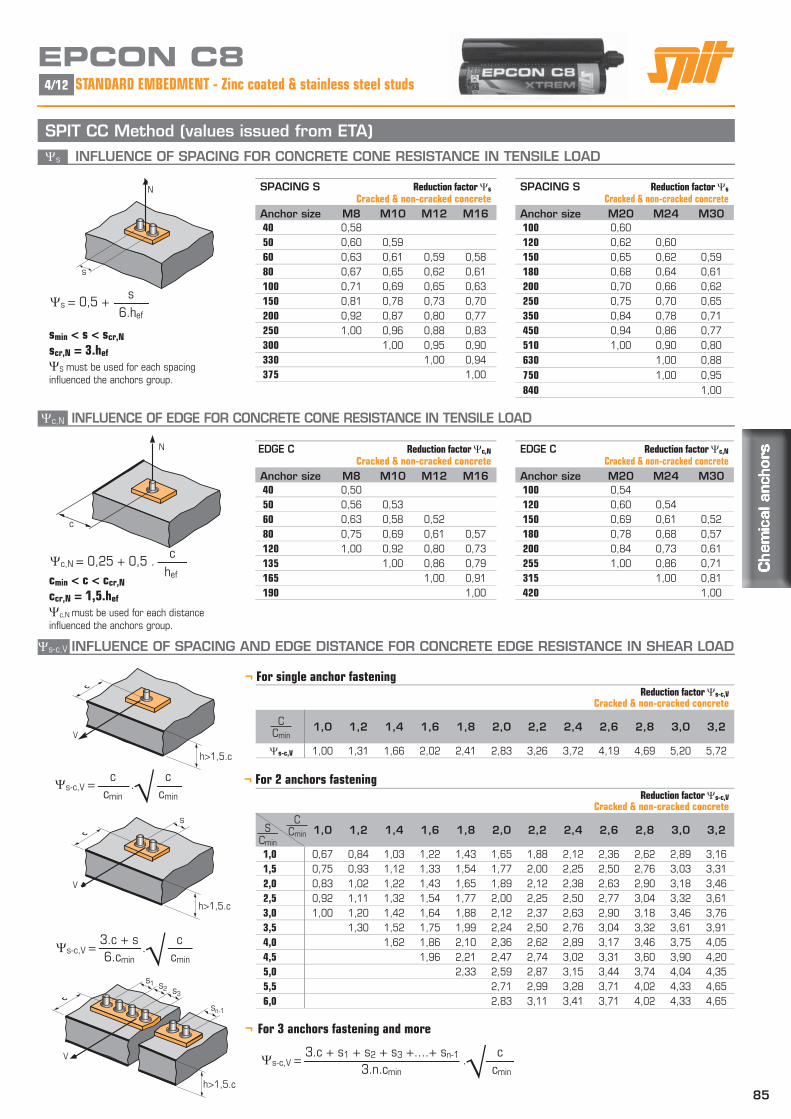
s INFLUENCE OF SPACING FOR CONCRETE CONE RESISTANCE IN TENSILE LOAD
c,N INFLUENCE OF EDGE FOR CONCRETE CONE RESISTANCE IN TENSILE LOAD
s-c,V INFLUENCE OF SPACING AND EDGE DISTANCE FOR CONCRETE EDGE RESISTANCE IN SHEAR LOAD
¬ For 2 anchors fastening
¬ For 3 anchors fastening and more
N
c
s
N
V
h>1,5.c
s
V
h>1,5.c
¬ For single anchor fastening
SPIT CC Method (values issued from ETA)
s1
V
s2 s3
sn-1
h>1,5.c
Reduction factor s-c,V
Cracked & non-cracked concrete
1,0 1,2 1,4 1,6 1,8 2,0 2,2 2,4 2,6 2,8 3,0 3,2
1,0 0,67 0,84 1,03 1,22 1,43 1,65 1,88 2,12 2,36 2,62 2,89 3,16
1,5 0,75 0,93 1,12 1,33 1,54 1,77 2,00 2,25 2,50 2,76 3,03 3,31
2,0 0,83 1,02 1,22 1,43 1,65 1,89 2,12 2,38 2,63 2,90 3,18 3,46
2,5 0,92 1,11 1,32 1,54 1,77 2,00 2,25 2,50 2,77 3,04 3,32 3,61
3,0 1,00 1,20 1,42 1,64 1,88 2,12 2,37 2,63 2,90 3,18 3,46 3,76
3,5 1,30 1,52 1,75 1,99 2,24 2,50 2,76 3,04 3,32 3,61 3,91
4,0 1,62 1,86 2,10 2,36 2,62 2,89 3,17 3,46 3,75 4,05
4,5 1,96 2,21 2,47 2,74 3,02 3,31 3,60 3,90 4,20
5,0 2,33 2,59 2,87 3,15 3,44 3,74 4,04 4,35
5,5 2,71 2,99 3,28 3,71 4,02 4,33 4,65
6,0 2,83 3,11 3,41 3,71 4,02 4,33 4,65
Cmin
C
Cmin
S
Reduction factor s-c,V
Cracked & non-cracked concrete
1,0 1,2 1,4 1,6 1,8 2,0 2,2 2,4 2,6 2,8 3,0 3,2
s-c,V 1,00 1,31 1,66 2,02 2,41 2,83 3,26 3,72 4,19 4,69 5,20 5,72
Cmin
C
s-c,V = c
. c
cmin cmin
s-c,V = 3.c + s
. c
6.cmin cmin
s-c,V = 3.c + s1 + s2 + s3 +....+ sn-1 .
c 3.n.cmin cmin
smin < s < scr,N
scr,N = 3.hef
S must be used for each spacing influenced the anchors group.
cmin < c < ccr,N
ccr,N = 1,5.hef
c,N must be used for each distance influenced the anchors group.
EPCON C8STANDARD EMBEDMENT - Zinc coated & stainless steel studs4/12
SPACING S Reduction factor s
Cracked & non-cracked concrete
Anchor size M20 M24 M30100 0,60
120 0,62 0,60
150 0,65 0,62 0,59
180 0,68 0,64 0,61
200 0,70 0,66 0,62
250 0,75 0,70 0,65
350 0,84 0,78 0,71
450 0,94 0,86 0,77
510 1,00 0,90 0,80
630 1,00 0,88
750 1,00 0,95
840 1,00
SPACING S Reduction factor s
Cracked & non-cracked concrete
Anchor size M8 M10 M12 M1640 0,58
50 0,60 0,59
60 0,63 0,61 0,59 0,58
80 0,67 0,65 0,62 0,61
100 0,71 0,69 0,65 0,63
150 0,81 0,78 0,73 0,70
200 0,92 0,87 0,80 0,77
250 1,00 0,96 0,88 0,83
300 1,00 0,95 0,90
330 1,00 0,94
375 1,00
EDGE C Reduction factor c,N
Cracked & non-cracked concrete
Anchor size M8 M10 M12 M1640 0,50
50 0,56 0,53
60 0,63 0,58 0,52
80 0,75 0,69 0,61 0,57
120 1,00 0,92 0,80 0,73
135 1,00 0,86 0,79
165 1,00 0,91
190 1,00
EDGE C Reduction factor c,N
Cracked & non-cracked concrete
Anchor size M20 M24 M30100 0,54
120 0,60 0,54
150 0,69 0,61 0,52
180 0,78 0,68 0,57
200 0,84 0,73 0,61
255 1,00 0,86 0,71
315 1,00 0,81
420 1,00
c,N = 0,25 + 0,5 . c
hef
s = 0,5 + s
6.hef

86
fb INFLUENCE OF CONCRETE f,V INFLUENCE OF SHEAR LOADING DIRECTION
β
V
90˚
180˚ 0˚
c
90°
≤ β ≤
180° 60°≤ β ≤90°
0°≤ β ≤60°
Concrete class fbC25/30 1,02
C30/40 1,08
C40/60 1,10
C50/60 1,12
Angle [°] f,V0 to 55 1
60 1,1
70 1,2
80 1,5
90 to 180 2
EPCON C8STANDARD EMBEDMENT - Zinc coated & stainless steel studs 5/12
SPIT CC Method (values issued from ETA - Seismic category C1)TENSILE in kN SHEAR in kN
NRd,C1 = min(NRd,p,C1 ; NRd,c,C1 ; NRd,s,C1)N = NSd / NRd,C1 1
VRd,C1 = min(VRd,c,C1 ; VRd,cp,C1 ; VRd,s,C1)V = VSd / VRd,C1 1
N + V 1,2
¬ Pull-out resistanceN
N0Rd,p,C1 Design pull-out resistance
Anchor size M10 M12 M16Category C1 - Single anchorhef 90 110 125N0Rd,p,C1 (C20/25) 9,7 13,1 23,7Category C1 - Group of anchors (1)
hef 90 110 125N0Rd,p,C1 (C20/25) 8,2 11,1 20,2(1) when more than one anchor of the group is submitted to tensile loadMc = 1,8
NRd,p,C1 = N0Rd,p,C1 . fb
¬ Concrete cone resistanceN
N0Rd,c,C1 Design cone resistance
Anchor size M10 M12 M16Category C1 - Single anchorhef 90 110 125N0Rd,c,C1 (C20/25) 9,4 12,4 19,0Category C1 - Group of anchors (1)
hef 90 110 125N0Rd,c,C1 (C20/25) 8,3 10,9 16,8(1) when more than one anchor of the group is submitted to tensile loadMc = 1,8
NRd,c,C1 = N0Rd,c,C1 . fb . s . c,N
¬ Concrete edge resistance V
V0Rd,c,C1 Design concrete edge resistance at minimum edge distance (Cmin)
Anchor size M10 M12 M16Category C1 - Single anchorhef 90 110 125Cmin 50 60 80Smin 45 55 65V0Rd,c,C1 (C20/25) 3,8 5,5 9,4Category C1 - Group of anchors (1)
hef 90 110 125Cmin 50 60 80Smin 45 55 65V0Rd,c,C1 (C20/25) 3,3 4,7 8,0(1) when more than one anchor of the group is submitted to shear loadMc = 1,5
VRd,c,C1 = V0Rd,c,C1 . fb . fV . S-C,V
¬ Pryout failureV
V0Rd,cp,C1 Design pryout resistance
Anchor size M10 M12 M16Category C1 - Single anchorhef 90 110 125V0Rd,cp,C1 (C20/25) 22,6 29,7 45,6Category C1 - Group of anchors (1)
hef 90 110 125V0Rd,cp,C1 (C20/25) 20,0 26,2 40,2(1) when more than one anchor of the group is submitted to shear loadMc = 1,5
VRd,cp,C1 = V0Rd,cp,C1 . fb . s . c,N
¬ Steel resistance
N
NRd,s,C1 Steel design tensile resistance
Anchor size M10 M12 M16MAXIMA stud Zn. 20,5 29,8 55,6MAXIMA stud A4 21,9 31,6 58,8Std. stud grade 5.8 19,3 28,0 52,0Std. stud grade 8.8 30,7 44,7 84,0(1) when more than one anchor of the group is submitted to tensile loadMAXIMA stud Zn. : Ms = 1,8 and MAXIMA stud A4: Ms = 1,87Std. stud grade 5.8 and 8.8 : Ms = 1,5
¬ Steel resistance (2)V
VRd,s,C1 Steel design shear resistance
Anchor size M10 M12 M16Category C1 - Single anchorMAXIMA stud Zn. 8,5 12,4 23,0MAXIMA stud A4 12,8 19,2 35,3Std. stud grade 5.8 8,1 11,8 21,8Std. stud grade 8.8 18,6 27,0 50,4Category C1 - Group of anchors (1)
MAXIMA stud Zn. 7,2 10,5 19,6MAXIMA stud A4 10,9 16,3 30,0Std. stud grade 5.8 6,9 10,0 18,6Std. stud grade 8.8 15,8 22,9 42,8(1) when more than one anchor of the group is submitted to shear load(2) In case of no hole clearance between anchor and fixture.MAXIMA stud Zn. : Ms = 1,43 and MAXIMA stud A4 : Ms = 1,56Std. stud grade 5.8 and 8.8 : Ms = 1,25

87
EPCON C8Seismic calculation with I-EXPERT software6/12

88
SPIT CC Method (values issued from ETA)TENSILE in kN SHEAR in kN
¬ Pull-out resistance
for dry and wet concrete (1)
N
¬ Concrete cone resistance
for dry and wet concrete (1)
N
¬ Pryout failureV
¬ Steel resistance
N
¬ Concrete edge resistance V
¬ Steel resistanceV
NRd = min(NRd,p ; NRd,c ; NRd,s)N = NSd / NRd 1
VRd = min(VRd,c ; VRd,cp ; VRd,s)V = VSd / VRd 1
N + V 1,2
β
V
90˚
180˚ 0˚
c
90°
≤ β ≤
180° 60°≤ β ≤90°
0°≤ β ≤60°
N0Rd,p Design pull-out resistance
Anchor size M8 M10 M12 M16 M20 M24 M30hef 95 120 144 192 220 280 330
Non-cracked concrete 21,2 33,5 48,3 80,4 107,5 152,5 224,6
Cracked concrete 12,6 19,9 27,1 45,6 65,3 99,7 121,0
Mc = 1,8
Angle [°] f,V0 to 55 1
60 1,1
70 1,2
80 1,5
90 to 180 2
NRd,p = N0Rd,p . fb
NRd,c = N0Rd,c . fb . s . c,N
VRd,c = V0Rd,c . fb . fV . S-C,V
VRd,cp = V0Rd,cp . fb . s . c,N
EPCON C8EMBEDMENT 12Ø - Zinc coated & stainless steel studs 7/12
N0Rd,c Design cone resistance
Anchor size M8 M10 M12 M16 M20 M24 M30hef 95 120 144 192 220 280 330
Non-cracked concrete 25,9 36,8 48,4 74,5 91,4 131,2 167,9
Cracked concrete 18,5 26,3 34,6 53,2 65,3 93,7 119,9
Mc = 1,8
V0Rd,c Design concrete edge resistance at minimum edge distance (Cmin)
Anchor size M8 M10 M12 M16 M20 M24 M30hef 95 120 144 192 220 280 330
Cmin 40 50 60 80 100 120 150
Smin 40 50 60 80 100 120 150
Non-cracked concrete 2,6 3,5 5,1 7,5 12,7 18,9 32,2
Cracked concrete 1,8 2,5 3,6 5,3 9 13,5 23
Mc = 1,5
V0Rd,cp Design pryout resistance
Anchor size M8 M10 M12 M16 M20 M24 M30hef 95 120 144 192 220 280 330
Non-cracked concrete 42,4 67,0 96,5 149,0 182,7 262,4 335,7
Cracked concrete 25,2 39,8 54,3 91,1 130,5 187,4 239,8
Mcp = 1,5
(1) The concrete in the area of the anchorage is water statured. The anchor may be installed in flooded holes, but the figures above cannot be used, you must use the values given in the ETA for the category 2.
Concrete class fbC25/30 1,02
C30/40 1,08
C40/60 1,10
C50/60 1,12
NRd,s Steel design tensile resistance
Anchor size M8 M10 M12 M16 M20 M24 M30MAXIMA stud Zn. 12,9 20,5 29,8 55,6 79,2 114,1 182,6
MAXIMA stud A4 12,3 19,8 28,9 54,5 85,0 122,5 -
Std. stud grade 5.8* 12,0 19,3 28,0 52,0 81,3 118,0 186,7
Std. stud grade 8.8* 19,3 30,7 44,7 84,0 130,7 188,0 299,3
Std. stud grade 10.9* 26,4 41,4 60,0 112,1 175,0 252,1 400,7
MAXIMA stud Zn. : Ms = 1,71 for M8 to M16 and Ms = 2,49 for M20 to M30
MAXIMA stud A4 : Ms = 1,87
Std. stud grade 5.8 and 8.8 : Ms = 1,5 and grade 10.9 : Ms = 1,4
* Special grade available on request.
VRd,s Steel design shear resistance
Anchor size M8 M10 M12 M16 M20 M24 M30MAXIMA stud Zn. 7,7 12,2 17,7 32,9 39,3 56,7 90,7
MAXIMA stud A4 7,3 11,9 17,3 32,7 51,3 73,1 -
Std. stud grade 5.8* 7,4 11,6 16,9 31,2 48,8 70,4 112,0
Std. stud grade 8.8* 11,7 18,6 27,0 50,4 78,4 112,8 179,2
Std. stud grade 10.9* 12,2 19,3 28,1 52,0 81,3 117,3 186,7
MAXIMA stud Zn. : Ms = 1,43 for M8 to M16 and Ms = 1,5 for M20 to M30
MAXIMA stud A4 : Ms = 1,56
Std. stud grade 5.8 and 8.8 : Ms = 1,25 and grade 10.9 : Ms = 1,5
* Special grade available on request.
fb INFLUENCE OF CONCRETE f,V INFLUENCE OF SHEAR LOADING DIRECTION

89
s INFLUENCE OF SPACING FOR CONCRETE CONE RESISTANCE IN TENSILE LOAD
c,N INFLUENCE OF EDGE FOR CONCRETE CONE RESISTANCE IN TENSILE LOAD
s-c,V INFLUENCE OF SPACING AND EDGE DISTANCE FOR CONCRETE EDGE RESISTANCE IN SHEAR LOAD
¬ For 2 anchors fastening
¬ For 3 anchors fastening and more
N
c
s
N
V
h>1,5.c
s
V
h>1,5.c
¬ For single anchor fastening
SPIT CC Method (values issued from ETA)
s1
V
s2 s3
sn-1
h>1,5.c
Reduction factor s-c,V
Cracked & non-cracked concrete
1,0 1,2 1,4 1,6 1,8 2,0 2,2 2,4 2,6 2,8 3,0 3,2
1,0 0,67 0,84 1,03 1,22 1,43 1,65 1,88 2,12 2,36 2,62 2,89 3,16
1,5 0,75 0,93 1,12 1,33 1,54 1,77 2,00 2,25 2,50 2,76 3,03 3,31
2,0 0,83 1,02 1,22 1,43 1,65 1,89 2,12 2,38 2,63 2,90 3,18 3,46
2,5 0,92 1,11 1,32 1,54 1,77 2,00 2,25 2,50 2,77 3,04 3,32 3,61
3,0 1,00 1,20 1,42 1,64 1,88 2,12 2,37 2,63 2,90 3,18 3,46 3,76
3,5 1,30 1,52 1,75 1,99 2,24 2,50 2,76 3,04 3,32 3,61 3,91
4,0 1,62 1,86 2,10 2,36 2,62 2,89 3,17 3,46 3,75 4,05
4,5 1,96 2,21 2,47 2,74 3,02 3,31 3,60 3,90 4,20
5,0 2,33 2,59 2,87 3,15 3,44 3,74 4,04 4,35
5,5 2,71 2,99 3,28 3,71 4,02 4,33 4,65
6,0 2,83 3,11 3,41 3,71 4,02 4,33 4,65
Cmin
C
Cmin
S
Reduction factor s-c,V
Cracked & non-cracked concrete
1,0 1,2 1,4 1,6 1,8 2,0 2,2 2,4 2,6 2,8 3,0 3,2
s-c,V 1,00 1,31 1,66 2,02 2,41 2,83 3,26 3,72 4,19 4,69 5,20 5,72
Cmin
C
s-c,V = c
. c
cmin cmin
s-c,V = 3.c + s
. c
6.cmin cmin
s-c,V = 3.c + s1 + s2 + s3 +....+ sn-1 .
c 3.n.cmin cmin
smin < s < scr,N
scr,N = 3.hef
S must be used for each spacing influenced the anchors group.
cmin < c < ccr,N
ccr,N = 1,5.hef
c,N must be used for each distance influenced the anchors group.
EPCON C8Zinc coated & stainless steel studs - EMBEDMENT 12Ø8/12
SPACING S Reduction factor s
Cracked & non-cracked concrete
Anchor size M20 M24 M30100 0,58
120 0,59 0,57
150 0,61 0,59 0,58
180 0,64 0,61 0,59
200 0,65 0,62 0,60
250 0,69 0,65 0,63
300 0,73 0,68 0,65
400 0,80 0,74 0,70
500 0,88 0,80 0,75
660 1,00 0,89 0,83
840 1,00 0,92
990 1,00
SPACING S Reduction factor s
Cracked & non-cracked concrete
Anchor size M8 M10 M12 M1640 0,57
50 0,59 0,57
60 0,61 0,58 0,57 0,55
80 0,64 0,61 0,59 0,57
100 0,68 0,64 0,62 0,59
150 0,76 0,71 0,67 0,63
200 0,85 0,78 0,73 0,67
290 1,00 0,90 0,84 0,75
360 1,00 0,92 0,81
435 1,00 0,88
580 1,00
EDGE C Reduction factor c,N
Cracked & non-cracked concrete
Anchor size M8 M10 M12 M1640 0,46
50 0,51 0,46
60 0,57 0,50 0,46
80 0,67 0,58 0,53 0,46
145 1,00 0,85 0,75 0,63
180 1,00 0,88 0,72
215 1,00 0,81
290 1,00
EDGE C Reduction factor c,N
Cracked & non-cracked concrete
Anchor size M20 M24 M30100 0,48
120 0,52 0,46
150 0,59 0,52 0,48
200 0,70 0,61 0,55
250 0,82 0,70 0,63
330 1,00 0,84 0,75
420 1,00 0,89
500 1,00
c,N = 0,25 + 0,5 . c
hef
s = 0,5 + s
6.hef

90
SPIT CC Method (values issued from ETA)TENSILE in kN SHEAR in kN
¬ Pull-out resistance
for dry and wet concrete (1)
N
¬ Concrete cone resistance
for dry and wet concrete (1)
N
¬ Pryout failureV
¬ Steel resistance
N
¬ Concrete edge resistance V
¬ Steel resistanceV
NRd = min(NRd,p ; NRd,c ; NRd,s)N = NSd / NRd 1
VRd = min(VRd,c ; VRd,cp ; VRd,s)V = VSd / VRd 1
N + V 1,2
β
V
90˚
180˚ 0˚
c
90°
≤ β ≤
180° 60°≤ β ≤90°
0°≤ β ≤60°
N0Rd,p Design pull-out resistance
Anchor size M8 M10 M12 M16 M20 M24 M30hef 128 160 192 256 320 384 480
Non-cracked concrete 28,6 44,7 64,3 107,2 156,4 209,1 326,7
Cracked concrete 17,0 26,5 36,2 60,8 94,9 136,7 175,9
Mc = 1,8
Angle [°] f,V0 to 55 1
60 1,1
70 1,2
80 1,5
90 to 180 2
NRd,p = N0Rd,p . fb
NRd,c = N0Rd,c . fb . s . c,N
VRd,c = V0Rd,c . fb . fV . S-C,V
VRd,cp = V0Rd,cp . fb . s . c,N
EPCON C8EMBEDMENT 16Ø - Zinc coated & stainless steel studs 9/12
N0Rd,c Design cone resistance
Anchor size M8 M10 M12 M16 M20 M24 M30hef 128 160 192 256 320 384 480
Non-cracked concrete 40,5 56,7 74,5 114,7 160,3 210,7 294,5
Cracked concrete 29,0 40,5 53,2 81,9 114,5 150,5 210,3
Mc = 1,8
NRd,s Steel design tensile resistance
Anchor size M8 M10 M12 M16 M20 M24 M30Std. stud grade 5.8* 12,0 19,3 28,0 52,0 81,3 118,0 186,7
Std. stud grade 8.8* 19,3 30,7 44,7 84,0 130,7 188,0 299,3
Std. stud grade 10.9* 26,4 41,4 60,0 112,1 175,0 252,1 400,7
Std. stud grade 5.8 and 8.8 : Ms = 1,5
Std. stud grade 10.9 : Ms = 1,4
* Special grade available on request.
V0Rd,c Design concrete edge resistance at minimum edge distance (Cmin)
Anchor size M8 M10 M12 M16 M20 M24 M30hef 128 160 192 256 320 384 480
Cmin 40 50 60 80 100 120 150
Smin 40 50 60 80 100 120 150
Non-cracked concrete 2,8 3,7 5,4 7,9 13,7 20,2 34,7
Cracked concrete 2,0 2,6 3,8 5,6 9,7 14,4 24,7
Mc = 1,5
V0Rd,cp Design pryout resistance
Anchor size M8 M10 M12 M16 M20 M24 M30hef 128 160 192 256 320 384 480
Non-cracked concrete 57,2 89,4 128,7 214,5 312,8 418,2 588,9
Cracked concrete 34,0 53,1 72,4 121,5 189,9 273,4 351,9
Mcp = 1,5
VRd,s Steel design shear resistance
Anchor size M8 M10 M12 M16 M20 M24 M30Std. stud grade 5.8* 7,4 11,6 16,9 31,2 48,8 70,4 112,0
Std. stud grade 8.8* 11,7 18,6 27,0 50,4 78,4 112,8 179,2
Std. stud grade 10.9* 12,2 19,3 28,1 52,0 81,3 117,3 186,7
Std. stud grade 5.8 and 8.8 : Ms = 1,25
Std. stud grade 10.9 : Ms = 1,5
* Special grade available on request.
(1) The concrete in the area of the anchorage is water statured. The anchor may be installed in flooded holes, but the figures above cannot be used, you must use the values given in the ETA for the category 2.
Concrete class fbC25/30 1,02
C30/40 1,08
C40/60 1,10
C50/60 1,12
fb INFLUENCE OF CONCRETE f,V INFLUENCE OF SHEAR LOADING DIRECTION

91
s INFLUENCE OF SPACING FOR CONCRETE CONE RESISTANCE IN TENSILE LOAD
c,N INFLUENCE OF EDGE FOR CONCRETE CONE RESISTANCE IN TENSILE LOAD
s-c,V INFLUENCE OF SPACING AND EDGE DISTANCE FOR CONCRETE EDGE RESISTANCE IN SHEAR LOAD
¬ For 2 anchors fastening
¬ For 3 anchors fastening and more
N
c
s
N
V
h>1,5.c
s
V
h>1,5.c
¬ For single anchor fastening
SPIT CC Method (values issued from ETA)
s1
V
s2 s3
sn-1
h>1,5.c
Reduction factor s-c,V
Cracked & non-cracked concrete
1,0 1,2 1,4 1,6 1,8 2,0 2,2 2,4 2,6 2,8 3,0 3,2
1,0 0,67 0,84 1,03 1,22 1,43 1,65 1,88 2,12 2,36 2,62 2,89 3,16
1,5 0,75 0,93 1,12 1,33 1,54 1,77 2,00 2,25 2,50 2,76 3,03 3,31
2,0 0,83 1,02 1,22 1,43 1,65 1,89 2,12 2,38 2,63 2,90 3,18 3,46
2,5 0,92 1,11 1,32 1,54 1,77 2,00 2,25 2,50 2,77 3,04 3,32 3,61
3,0 1,00 1,20 1,42 1,64 1,88 2,12 2,37 2,63 2,90 3,18 3,46 3,76
3,5 1,30 1,52 1,75 1,99 2,24 2,50 2,76 3,04 3,32 3,61 3,91
4,0 1,62 1,86 2,10 2,36 2,62 2,89 3,17 3,46 3,75 4,05
4,5 1,96 2,21 2,47 2,74 3,02 3,31 3,60 3,90 4,20
5,0 2,33 2,59 2,87 3,15 3,44 3,74 4,04 4,35
5,5 2,71 2,99 3,28 3,71 4,02 4,33 4,65
6,0 2,83 3,11 3,41 3,71 4,02 4,33 4,65
Cmin
C
Cmin
S
Reduction factor s-c,V
Cracked & non-cracked concrete
1,0 1,2 1,4 1,6 1,8 2,0 2,2 2,4 2,6 2,8 3,0 3,2
s-c,V 1,00 1,31 1,66 2,02 2,41 2,83 3,26 3,72 4,19 4,69 5,20 5,72
Cmin
C
s-c,V = c
. c
cmin cmin
s-c,V = 3.c + s
. c
6.cmin cmin
s-c,V = 3.c + s1 + s2 + s3 +....+ sn-1 .
c 3.n.cmin cmin
smin < s < scr,N
scr,N = 3.hef
S must be used for each spacing influenced the anchors group.
cmin < c < ccr,N
ccr,N = 1,5.hef
c,N must be used for each distance influenced the anchors group.
EPCON C8Zinc coated & stainless steel studs - EMBEDMENT 16Ø 10/12
SPACING S Reduction factor s
Cracked & non-cracked concrete
Anchor size M20 M24 M30100 0,55
120 0,56 0,55
150 0,58 0,57 0,55
250 0,63 0,61 0,59
350 0,68 0,65 0,62
550 0,79 0,74 0,69
650 0,84 0,78 0,73
750 0,89 0,83 0,76
850 0,94 0,87 0,80
960 1,00 0,92 0,83
1150 1,00 0,90
1440 1,00
SPACING S Reduction factor s
Cracked & non-cracked concrete
Anchor size M8 M10 M12 M1640 0,55
50 0,57 0,55
60 0,58 0,56 0,55 0,54
80 0,60 0,58 0,57 0,55
120 0,66 0,63 0,60 0,58
200 0,76 0,71 0,67 0,63
250 0,83 0,76 0,72 0,66
385 1,00 0,90 0,83 0,75
480 1,00 0,92 0,81
580 1,00 0,88
770 1,00
EDGE C Reduction factor c,N
Cracked & non-cracked concrete
Anchor size M8 M10 M12 M1640 0,41
50 0,45 0,41
60 0,48 0,44 0,41
80 0,56 0,50 0,46 0,41
190 0,99 0,84 0,74 0,62
240 1,00 0,88 0,72
290 1,00 0,82
385 1,00
EDGE C Reduction factor c,N
Cracked & non-cracked concrete
Anchor size M20 M24 M30100 0,41
120 0,44 0,41
150 0,48 0,45 0,41
250 0,64 0,58 0,51
300 0,72 0,64 0,56
480 1,00 0,88 0,75
580 1,00 0,85
720 1,00
c,N = 0,25 + 0,5 . c
hef
s = 0,5 + s
6.hef
92
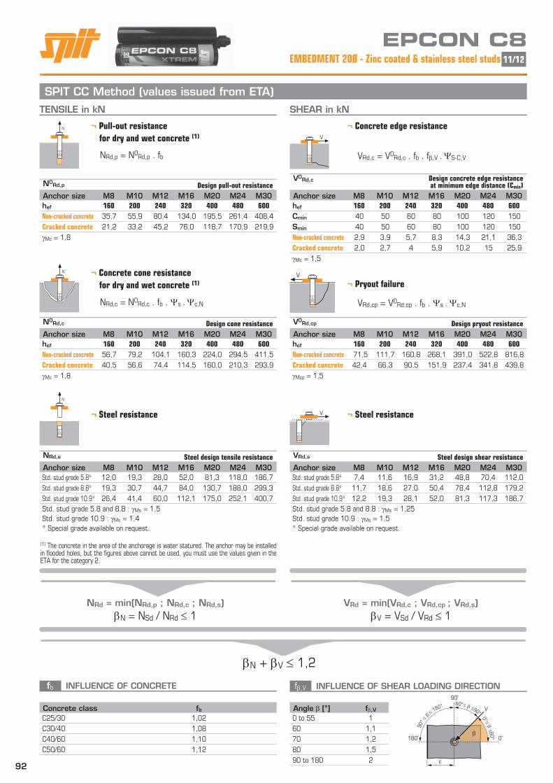
SPIT CC Method (values issued from ETA)TENSILE in kN SHEAR in kN
¬ Pull-out resistance
for dry and wet concrete (1)
N
¬ Concrete cone resistance
for dry and wet concrete (1)
N
¬ Pryout failureV
¬ Steel resistance
N
¬ Concrete edge resistance V
¬ Steel resistanceV
NRd = min(NRd,p ; NRd,c ; NRd,s)N = NSd / NRd 1
VRd = min(VRd,c ; VRd,cp ; VRd,s)V = VSd / VRd 1
N + V 1,2
β
V
90˚
180˚ 0˚
c
90°
≤ β ≤
180° 60°≤ β ≤90°
0°≤ β ≤60°
N0Rd,p Design pull-out resistance
Anchor size M8 M10 M12 M16 M20 M24 M30hef 160 200 240 320 400 480 600
Non-cracked concrete 35,7 55,9 80,4 134,0 195,5 261,4 408,4
Cracked concrete 21,2 33,2 45,2 76,0 118,7 170,9 219,9
Mc = 1,8
Angle [°] f,V0 to 55 1
60 1,1
70 1,2
80 1,5
90 to 180 2
NRd,p = N0Rd,p . fb
NRd,c = N0Rd,c . fb . s . c,N
VRd,c = V0Rd,c . fb . fV . S-C,V
VRd,cp = V0Rd,cp . fb . s . c,N
EPCON C8EMBEDMENT 20Ø - Zinc coated & stainless steel studs 11/12
N0Rd,c Design cone resistance
Anchor size M8 M10 M12 M16 M20 M24 M30hef 160 200 240 320 400 480 600
Non-cracked concrete 56,7 79,2 104,1 160,3 224,0 294,5 411,5
Cracked concrete 40,5 56,6 74,4 114,5 160,0 210,3 293,9
Mc = 1,8
NRd,s Steel design tensile resistance
Anchor size M8 M10 M12 M16 M20 M24 M30Std. stud grade 5.8* 12,0 19,3 28,0 52,0 81,3 118,0 186,7
Std. stud grade 8.8* 19,3 30,7 44,7 84,0 130,7 188,0 299,3
Std. stud grade 10.9* 26,4 41,4 60,0 112,1 175,0 252,1 400,7
Std. stud grade 5.8 and 8.8 : Ms = 1,5
Std. stud grade 10.9 : Ms = 1,4
* Special grade available on request.
V0Rd,c Design concrete edge resistance at minimum edge distance (Cmin)
Anchor size M8 M10 M12 M16 M20 M24 M30hef 160 200 240 320 400 480 600
Cmin 40 50 60 80 100 120 150
Smin 40 50 60 80 100 120 150
Non-cracked concrete 2,9 3,9 5,7 8,3 14,3 21,1 36,3
Cracked concrete 2,0 2,7 4 5,9 10,2 15 25,9
Mc = 1,5
V0Rd,cp Design pryout resistance
Anchor size M8 M10 M12 M16 M20 M24 M30hef 160 200 240 320 400 480 600
Non-cracked concrete 71,5 111,7 160,8 268,1 391,0 522,8 816,8
Cracked concrete 42,4 66,3 90,5 151,9 237,4 341,8 439,8
Mcp = 1,5
VRd,s Steel design shear resistance
Anchor size M8 M10 M12 M16 M20 M24 M30Std. stud grade 5.8* 7,4 11,6 16,9 31,2 48,8 70,4 112,0
Std. stud grade 8.8* 11,7 18,6 27,0 50,4 78,4 112,8 179,2
Std. stud grade 10.9* 12,2 19,3 28,1 52,0 81,3 117,3 186,7
Std. stud grade 5.8 and 8.8 : Ms = 1,25
Std. stud grade 10.9 : Ms = 1,5
* Special grade available on request.
(1) The concrete in the area of the anchorage is water statured. The anchor may be installed in flooded holes, but the figures above cannot be used, you must use the values given in the ETA for the category 2.
Concrete class fbC25/30 1,02
C30/40 1,08
C40/60 1,10
C50/60 1,12
fb INFLUENCE OF CONCRETE f,V INFLUENCE OF SHEAR LOADING DIRECTION

93
s INFLUENCE OF SPACING FOR CONCRETE CONE RESISTANCE IN TENSILE LOAD
c,N INFLUENCE OF EDGE FOR CONCRETE CONE RESISTANCE IN TENSILE LOAD
s-c,V INFLUENCE OF SPACING AND EDGE DISTANCE FOR CONCRETE EDGE RESISTANCE IN SHEAR LOAD
¬ For 2 anchors fastening
¬ For 3 anchors fastening and more
N
c
s
N
V
h>1,5.c
s
V
h>1,5.c
¬ For single anchor fastening
SPIT CC Method (values issued from ETA)
s1
V
s2 s3
sn-1
h>1,5.c
Reduction factor s-c,V
Cracked & non-cracked concrete
1,0 1,2 1,4 1,6 1,8 2,0 2,2 2,4 2,6 2,8 3,0 3,2
1,0 0,67 0,84 1,03 1,22 1,43 1,65 1,88 2,12 2,36 2,62 2,89 3,16
1,5 0,75 0,93 1,12 1,33 1,54 1,77 2,00 2,25 2,50 2,76 3,03 3,31
2,0 0,83 1,02 1,22 1,43 1,65 1,89 2,12 2,38 2,63 2,90 3,18 3,46
2,5 0,92 1,11 1,32 1,54 1,77 2,00 2,25 2,50 2,77 3,04 3,32 3,61
3,0 1,00 1,20 1,42 1,64 1,88 2,12 2,37 2,63 2,90 3,18 3,46 3,76
3,5 1,30 1,52 1,75 1,99 2,24 2,50 2,76 3,04 3,32 3,61 3,91
4,0 1,62 1,86 2,10 2,36 2,62 2,89 3,17 3,46 3,75 4,05
4,5 1,96 2,21 2,47 2,74 3,02 3,31 3,60 3,90 4,20
5,0 2,33 2,59 2,87 3,15 3,44 3,74 4,04 4,35
5,5 2,71 2,99 3,28 3,71 4,02 4,33 4,65
6,0 2,83 3,11 3,41 3,71 4,02 4,33 4,65
Cmin
C
Cmin
S
Reduction factor s-c,V
Cracked & non-cracked concrete
1,0 1,2 1,4 1,6 1,8 2,0 2,2 2,4 2,6 2,8 3,0 3,2
s-c,V 1,00 1,31 1,66 2,02 2,41 2,83 3,26 3,72 4,19 4,69 5,20 5,72
Cmin
C
s-c,V = c
. c
cmin cmin
s-c,V = 3.c + s
. c
6.cmin cmin
s-c,V = 3.c + s1 + s2 + s3 +....+ sn-1 .
c 3.n.cmin cmin
smin < s < scr,N
scr,N = 3.hef
S must be used for each spacing influenced the anchors group.
cmin < c < ccr,N
ccr,N = 1,5.hef
c,N must be used for each distance influenced the anchors group.
EPCON C8Zinc coated & stainless steel studs - EMBEDMENT 20Ø 12/12
SPACING S Reduction factor s
Cracked & non-cracked concrete
Anchor size M20 M24 M30100 0,54
120 0,55 0,54
150 0,56 0,55 0,54
250 0,60 0,59 0,57
350 0,65 0,62 0,60
450 0,69 0,66 0,63
600 0,75 0,71 0,67
800 0,83 0,78 0,72
1000 0,92 0,85 0,78
1200 1,00 0,92 0,83
1450 1,00 0,90
1800 1,00
SPACING S Reduction factor s
Cracked & non-cracked concrete
Anchor size M8 M10 M12 M1640 0,54
50 0,55 0,54
60 0,56 0,55 0,54 0,53
80 0,58 0,57 0,56 0,54
150 0,66 0,63 0,60 0,58
250 0,76 0,71 0,67 0,63
350 0,86 0,79 0,74 0,68
480 1,00 0,90 0,83 0,75
600 1,00 0,92 0,81
720 1,00 0,88
960 1,00
EDGE C Reduction factor c,N
Cracked & non-cracked concrete
Anchor size M8 M10 M12 M1640 0,38
50 0,41 0,38
60 0,44 0,40 0,38
80 0,50 0,45 0,42 0,38
240 1,00 0,85 0,75 0,63
300 1,00 0,88 0,72
360 1,00 0,81
480 1,00
EDGE C Reduction factor c,N
Cracked & non-cracked concrete
Anchor size M20 M24 M30100 0,38
120 0,40 0,38
150 0,44 0,41 0,38
250 0,56 0,51 0,46
400 0,75 0,67 0,58
600 1,00 0,88 0,75
720 1,00 0,85
900 1,00
c,N = 0,25 + 0,5 . c
hef
s = 0,5 + s
6.hef