
EPM Power Leader - GE Grid Solutions 1–2: EPM 5100 Metered Functions (ctd.) Alternate Scroll, Wye...
86
GE Consumer & Industrial Multilin EPM 5100 Electronic Power Meter INSTRUCTION MANUAL Manual P/N: 1601-0164-A2 Manual Order Code: GEK-113391A Copyright © 2008 GE Multilin GE Multilin 215 Anderson Avenue, Markham, Ontario Canada L6E 1B3 Tel: (905) 294-6222 Fax: (905) 201-2098 Internet: http://www.GEindustrial.com/multilin 1601-0164-A2 ISO9001:2000 G E M U L T I L I N R E G I S T E R E D GE Multilin's Quality Management System is registered to ISO9001:2000 QMI # 005094 UL # A3775
Transcript of EPM Power Leader - GE Grid Solutions 1–2: EPM 5100 Metered Functions (ctd.) Alternate Scroll, Wye...

GE Consumer & IndustrialMultilin
EPM 5100Electronic Power MeterINSTRUCTION MANUAL
Manual P/N: 1601-0164-A2Manual Order Code: GEK-113391A
Copyright © 2008 GE Multilin
GE Multilin
215 Anderson Avenue, Markham, Ontario
Canada L6E 1B3
Tel: (905) 294-6222 Fax: (905) 201-2098
Internet: http://www.GEindustrial.com/multilin
1601-0164-A2
ISO9001:2000GE MULT I L
I N
RE
GISTERED
GE Multilin's Quality Management System is registered to ISO9001:2000
QMI # 005094UL # A3775


CHAPTER 4:
EPM 5100 ELECTRONIC POWER METER – USER GUIDE 4–1
Table of Contents
1: OVERVIEW PRODUCT DESCRIPTION ............................................................................................................... 1-1FEATURES ............................................................................................................................................ 1-3
METERED FUNCTIONS ......................................................................................................... 1-3POWER MANAGEMENT FEATURES .................................................................................... 1-4
PHYSICAL DESCRIPTION ............................................................................................................... 1-6FRONT PANEL ...................................................................................................................... 1-6DISPLAY ................................................................................................................................ 1-6BACK PANEL ......................................................................................................................... 1-6PANEL MOUNTING .............................................................................................................. 1-7DIMENSIONS, CASE TYPE UNIT ......................................................................................... 1-8DIMENSIONS, PANEL MOUNTING UNIT ............................................................................ 1-9
ORDERING ........................................................................................................................................... 1-11ORDER CODES ..................................................................................................................... 1-11ACCESSORIES ....................................................................................................................... 1-11
APPLICATIONS ................................................................................................................................... 1-12TYPICAL APPLICATIONS ....................................................................................................... 1-12PT AND CT INPUTS ............................................................................................................. 1-12
SPECIFICATIONS ............................................................................................................................... 1-13INPUTS .................................................................................................................................. 1-13INTERCONNECTIONS ............................................................................................................ 1-13ENVIRONMENTAL ................................................................................................................. 1-13
2: INSTALLATION OVERVIEW ........................................................................................................................................... 2-1INSTALLATION PROCESS ..................................................................................................... 2-1
MECHANICAL INSTALLATION ..................................................................................................... 2-3PANEL MOUNTING FOR NEW INSTALLATION .................................................................. 2-3RETROFIT INSTALLATION ..................................................................................................... 2-4
ELECTRICAL INSTALLATION ......................................................................................................... 2-10INSTRUMENT TRANSFORMER CONNECTIONS ................................................................... 2-10PULSE INITIATION CONNECTIONS ..................................................................................... 2-13
COMMUNICATIONS INSTALLATION ......................................................................................... 2-15MODBUS CONNECTIONS .................................................................................................... 2-15INSTALLATION OF THE COMMUNICATIONS CARD ........................................................... 2-15
3: METERING METER OPERATIONS ....................................................................................................................... 3-1METER SELF-TEST ............................................................................................................... 3-1INTEGRITY OF METERED VALUES ....................................................................................... 3-1COMMUNICATIONS ERROR ................................................................................................. 3-2DISPLAY OF METERED VALUES .......................................................................................... 3-2KEYPAD FUNCTIONS ............................................................................................................ 3-2METERING ACCURACIES ..................................................................................................... 3-3
WYE CONFIGURATION METERING FUNCTIONS ................................................................. 3-4DESCRIPTION ........................................................................................................................ 3-4CURRENT (RMS) .................................................................................................................... 3-4VOLTAGE ............................................................................................................................... 3-4POWER .................................................................................................................................. 3-4

4–2 EPM 5100 ELECTRONIC POWER METER – USER GUIDE
CHAPTER 4:
APPARENT POWER .............................................................................................................. 3-5ENERGY ................................................................................................................................. 3-5FREQUENCY .......................................................................................................................... 3-5DEMAND ............................................................................................................................... 3-5POWER FACTOR ................................................................................................................... 3-6MISCELLANEOUS FUNCTIONS ............................................................................................ 3-6TRANSFORMER RATIOS ....................................................................................................... 3-6
DELTA CONFIGURATION METERING FUNCTIONS .............................................................. 3-7DESCRIPTION ........................................................................................................................ 3-7CURRENT (RMS) .................................................................................................................... 3-7LINE-TO-LINE VOLTAGE (RMS) ........................................................................................... 3-7POWER .................................................................................................................................. 3-7ENERGY ................................................................................................................................. 3-8FREQUENCY .......................................................................................................................... 3-8DEMAND ............................................................................................................................... 3-8POWER FACTOR ................................................................................................................... 3-8MISCELLANEOUS FUNCTIONS ............................................................................................ 3-9TRANSFORMER RATIOS ....................................................................................................... 3-9
4: PROGRAMMING PROGRAM MODE .............................................................................................................................. 4-1INTRODUCTION ..................................................................................................................... 4-1
ACCESS TO PROGRAM FUNCTIONS ......................................................................................... 4-2OVERVIEW ............................................................................................................................ 4-2RESTRICTED ACCESS ........................................................................................................... 4-3EXITING PROGRAM MODE .................................................................................................. 4-4
DATA RESETTING .............................................................................................................................. 4-5DESCRIPTION ........................................................................................................................ 4-5DEMAND RESET ................................................................................................................... 4-5ENERGY RESET ..................................................................................................................... 4-5METER INITIALIZE ................................................................................................................. 4-6ERRORS CLEAR ..................................................................................................................... 4-6
DATA FORMATTING ......................................................................................................................... 4-7OVERVIEW ............................................................................................................................ 4-7NORMAL SCROLL ................................................................................................................. 4-7ENERGY FORMAT ................................................................................................................. 4-9DEMAND FORMAT ............................................................................................................... 4-9VOLTAGE FORMAT ............................................................................................................... 4-10CURRENT FORMAT ............................................................................................................... 4-10LEADING ZEROS ................................................................................................................... 4-10SCROLL TIME ........................................................................................................................ 4-10
COMMUNICATIONS VALUES ....................................................................................................... 4-12COMMUNICATION ADDRESS SETUP .................................................................................. 4-12BAUD RATE SETUP .............................................................................................................. 4-12EPM COMPATIBILITY SETUP .............................................................................................. 4-13
PULSE OUTPUTS ............................................................................................................................... 4-14PULSE OUTPUT SETUP ........................................................................................................ 4-14UPGRADING FROM ELECTROMECHANICAL METERS ........................................................ 4-14UPGRADE CALCULATION EXAMPLE ................................................................................... 4-15
CONFIGURATION .............................................................................................................................. 4-16OPTIONS ............................................................................................................................... 4-16PT RATIO .............................................................................................................................. 4-16CT RATIO .............................................................................................................................. 4-16DEMAND PERIOD SETUP .................................................................................................... 4-17

CHAPTER 4:
EPM 5100 ELECTRONIC POWER METER – USER GUIDE 4–3
METER TYPE ......................................................................................................................... 4-17RESTRICTED ACCESS FUNCTIONS ............................................................................................ 4-18
ACCESS RESTRICT ................................................................................................................ 4-18NEW PASSWORD ................................................................................................................. 4-18
DEFAULT SETTINGS ......................................................................................................................... 4-19DESCRIPTION ........................................................................................................................ 4-19
5: COMMUNICATIONS INTRODUCTION ................................................................................................................................ 5-1OVERVIEW ............................................................................................................................ 5-1EVENTS .................................................................................................................................. 5-1MODBUS REGISTER MAPS .................................................................................................. 5-2MODBUS FORMAT CODES .................................................................................................. 5-5
6: MISCELLANEOUS TROUBLESHOOTING ....................................................................................................................... 6-1TROUBLESHOOTING GUIDE ................................................................................................ 6-1
REVISION HISTORY .......................................................................................................................... 6-4RELEASE DATES ................................................................................................................... 6-4
WARRANTY ......................................................................................................................................... 6-5GE MULTILIN WARRANTY .................................................................................................. 6-5

4–4 EPM 5100 ELECTRONIC POWER METER – USER GUIDE
CHAPTER 4:

EPM 5100 ELECTRONIC POWER METER – USER GUIDE 1–1
EPM 5100 Electronic Power Meter
Chapter 1: Overview
GE Consumer & IndustrialMultilin
Overview
1.1 Product Description
The GE Multilin EPM 5100 Electronic Power Meter is a full-function electronic meter with optional pulse initiation and communications features. The communications option supports the ‘open-architecture’ Modbus protocol and can be easily installed in the field at a later date. The EPM 5100 is available with the following mounting options:
• An industry-standard SI-compatible case to maintain drawout capability, allowing for easy upgrade or retrofit from existing DS-63, DS-64, or DS-65 electromechanical watthour meters (case type unit).
• A light compact plastic enclosure for panel mounting (panel mount unit).
The EPM 5100 continuously monitors specified line characteristics and displays the desired functions and calculated values on a two-line, alphanumeric liquid crystal display (LCD) on the front panel. The meter samples each of the current and voltage inputs 480 times per second, and the display is updated every three seconds.

1–2 EPM 5100 ELECTRONIC POWER METER – USER GUIDE
CHAPTER 1: OVERVIEW
FIGURE 1–1: EPM 5100 Meter
Metered and calculated values appearon the two-line liquid crystal display. Thevalue appears first, followed by theparamter name. The parameters appearin the order listed on the inside ofthe door.
Press the SELECT ENTER key to switchbetween normal and alternate scroll inMetering mode or to select functions andoptions in Program mode.
Press the SCROLL keys to scroll throughthe metered functions in the Metering modeor through the menus of functions andoptions in the Program mode.
Open the door at the bottom of the frontcover to adjust the display contrast or toview the list of measured parameters.

CHAPTER 1: OVERVIEW
EPM 5100 ELECTRONIC POWER METER – USER GUIDE 1–3
1.2 Features
1.2.1 Metered FunctionsThe electrical parameters and status information monitored and displayed by the EPM 5100 are shown in the following table. Note that the displayed parameters are dependent on whether the meter is configured as Wye or Delta.
Table 1–1: EPM 5100 Metered Functions
Normal Scroll, Wye Normal Scroll, Delta
Current (rms) phase A, B, C, and neutral Current, phase A, B, and C
Voltage (rms) phase A-N, B-N, and C-N Voltage (rms) phase A-B, B-C, and C-A
Voltage (rms) phase A-B, B-C, and C-A Watts, phase A-B, B-C, and total
Watts, phase A, B, C, and total Watts, demand and peak demand
Watts, demand and peak demand Vars, phase A-B, B-C, and total
Vars, phase A, B, C, and total VA, phase A-B, B-C, and total
VA, phase A, B, C, and total Power Factor, Total
Power factor, total Watthours, Total
Watthours, total Varhours, total lag (+) and total lead (–)
Varhours, total lag (+) and total lead (–) VAhours, Total
VAhours, total Frequency, in hertz
Frequency, in hertz
1–4 EPM 5100 ELECTRONIC POWER METER – USER GUIDE
CHAPTER 1: OVERVIEW
1.2.2 Power Management FeaturesThe EPM 5100 is available with the Power Leader communications options cards (catalog number PLA3CMAG01 for Modbus RTU). The Modbus option provides the following additional features:
• Remote viewing of all metered functions and configuration data at the host computer.
• Graphical trending of most metered functions.
• User-defined remote alarms.
• Extensive reporting capabilities, including dynamic data exchange (DDE) for exporting data for analysis by external software.
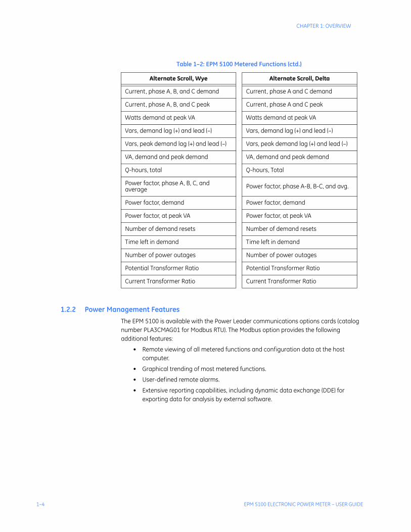
Table 1–2: EPM 5100 Metered Functions (ctd.)
Alternate Scroll, Wye Alternate Scroll, Delta
Current, phase A, B, and C demand Current, phase A and C demand
Current, phase A, B, and C peak Current, phase A and C peak
Watts demand at peak VA Watts demand at peak VA
Vars, demand lag (+) and lead (–) Vars, demand lag (+) and lead (–)
Vars, peak demand lag (+) and lead (–) Vars, peak demand lag (+) and lead (–)
VA, demand and peak demand VA, demand and peak demand
Q-hours, total Q-hours, Total
Power factor, phase A, B, C, and average Power factor, phase A-B, B-C, and avg.
Power factor, demand Power factor, demand
Power factor, at peak VA Power factor, at peak VA
Number of demand resets Number of demand resets
Time left in demand Time left in demand
Number of power outages Number of power outages
Potential Transformer Ratio Potential Transformer Ratio
Current Transformer Ratio Current Transformer Ratio

CHAPTER 1: OVERVIEW
EPM 5100 ELECTRONIC POWER METER – USER GUIDE 1–5
The following figure contains an example of a Power Leader power management system using the EPM 5100 and other Power Leader devices.
FIGURE 1–2: Example Power Leader System
HOST
EPM PowerLeader™ Meter
Spectra RMS™Extended FunctionModules
EPM Power Leader™Monitor (remote)
Power LeaderJunction Box
8000 LineMotor Control Center
Power LeaderRepeater
EPM PowerLeader™ Meter
EPM PowerLeader™ Meter
Power/VAC MediumVoltage Switchgear
AKD-8 Low-VoltageSwitchgear
MDPOvercurrentRelays withComnet MicroVersaTrip PM™
Trip Units inAKR Low-VoltageCircuit Breakers
Power BreakLow-Voltage Switchboard
EPM PowerLeader™ Monitor
MicroVersaTrip PM™Trip Units in Power BreakCircuit Breakers

1–6 EPM 5100 ELECTRONIC POWER METER – USER GUIDE
CHAPTER 1: OVERVIEW
1.3 Physical Description
1.3.1 Front PanelThe front panel has a two-line, 16-character per line LCD and a three-button keypad for view data and configuring the meter. The communication port and the voltage, current, and pulse initiation terminals are located on the back of the meter.
The front panel contains the following features:
• A 3.8" by 0.9" two-line LCD that can display up to 16 characters per line.
• Three pushbuttons for scroll up, scroll down, and alternate scroll/enter. Operating procedures for these buttons are described in Chapter 3.
• An additional secret button for accessing the Program mode. Operating procedures for the Program mode are described in Chapter 4.
• A complete list of available metering and a display contrast-adjustment knob are located under a flip-down door.
1.3.2 DisplayAny of the metered functions can be viewed by pressing the SCROLL buttons or allowing the EPM 5100 to automatically scroll through the parameters. All metered values are updated every three seconds, whether or not they are being displayed at the time. Press the SELECT/ENTER button to toggle between the normal and alternate scrolls.
1.3.3 Back PanelThe meter interconnections are located on the back panel as shown in the following figure. These include:
• Terminal studs for the voltage and current inputs.
• Two terminal blocks for the optional pulse initiation outputs.
• A Power Leader communications port.

CHAPTER 1: OVERVIEW
EPM 5100 ELECTRONIC POWER METER – USER GUIDE 1–7
FIGURE 1–3: Back Panel View
1.3.4 Panel MountingThe EPM 5100 is designed to mount semi-flush on motor control center, switchboard, or switchgear accessory doors or panels within easy reach of an operator. The cutout for the EPM 5100 is shown below and is identical to the industry-standard SI case for DS-63 and DS-65 electromechanical watthour meters. The case has four mounting holes that accept #10-32 × 3/8" (plus mounting panel thickness) screws. The meter is mounted through the front of the door or panel. The EPM 5100 may be installed on an existing DS-64 cutout using the PLE2ADPG01 adapter plate.
Do not use screws longer than 3/8" plus the mounting panel thickness. Longer screws may damage or interfere with the front panel retaining tabs.
NOTE
1–8 EPM 5100 ELECTRONIC POWER METER – USER GUIDE
CHAPTER 1: OVERVIEW
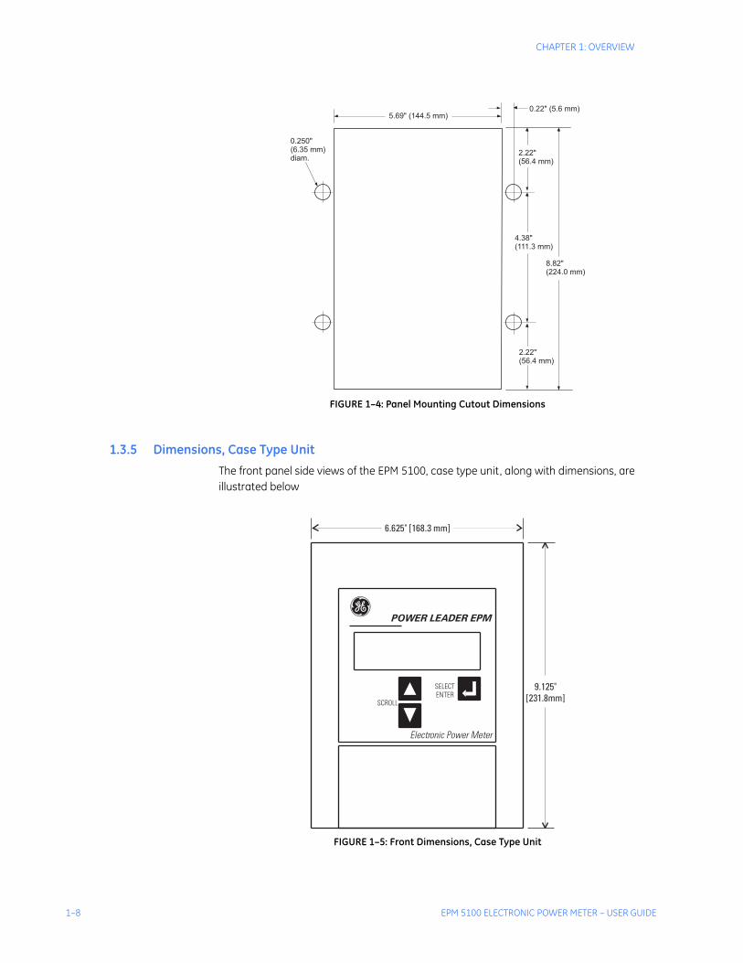
FIGURE 1–4: Panel Mounting Cutout Dimensions
1.3.5 Dimensions, Case Type UnitThe front panel side views of the EPM 5100, case type unit, along with dimensions, are illustrated below
FIGURE 1–5: Front Dimensions, Case Type Unit
5.69" (144.5 mm)0.22" (5.6 mm)
2.22"(56.4 mm)
4.38"(111.3 mm)
8.82"(224.0 mm)
2.22"(56.4 mm)
0.250"(6.35 mm)diam.
g POWER LEADER EPM
SCROLL
SELECTENTER
Electronic Power Meter
6.625" [168.3 mm]
9.125"[231.8mm]

CHAPTER 1: OVERVIEW
EPM 5100 ELECTRONIC POWER METER – USER GUIDE 1–9
FIGURE 1–6: Side Dimensions, Case Type Unit
1.3.6 Dimensions, Panel Mounting UnitThe front panel side views of the EPM 5100, panel mount unit, along with dimensions, are illustrated below
FIGURE 1–7: Front Dimensions, Panel Mount Unit
6.188"[157.2 mm]1.130"
[33.3 mm]
0.75"[19.1 mm]
8.4"[213 mm]
9.125"[238.8 mm]
6.875" [174.63mm]
6.750" [171.45mm]
9.350"[237.5mm]

1–10 EPM 5100 ELECTRONIC POWER METER – USER GUIDE
CHAPTER 1: OVERVIEW
FIGURE 1–8: Side Dimensions, Panel Mount Unit
8.84"
3.1" INSIDE PANEL
4.53" + PANEL THICKNESS
9.5"

CHAPTER 1: OVERVIEW
EPM 5100 ELECTRONIC POWER METER – USER GUIDE 1–11
1.4 Ordering
1.4.1 Order CodesThe order codes for the EPM 5100 Electronic Power Meter are shown below.
1.4.2 AccessoriesThe following accessories are available separately.
Table 1–3: EPM 5100 Order CodesPLE3 – * – * – *
Base Unit PLE3 | | | EPM 5100 Electronic Power Meter
Case/PanelES | | Case Type
PNL | | Panel Type
Voltage Inputs
A | 69 V AC rmsB | 120 V AC rmsC | 240 V AC rmsD | 277 V AC rmsF | 480 V AC rmsG | 600 V AC rms
Pulse Output/ Modbus CardG01 with pulse outputG14 with pulse output and Modbus card
Order Code Description
PLA3CMAG01 Modbus card
PLE3CSEG01 EPM 5100 Electronic Power Meter case
PLE2RPG01 EPM 5100 Electronic Power Meter cover
PLE2ADPG01 Mounting plate

1–12 EPM 5100 ELECTRONIC POWER METER – USER GUIDE
CHAPTER 1: OVERVIEW
1.5 Applications
1.5.1 Typical ApplicationsThe EPM 5100 Electronic Power Meter can be used on three- or four-wire, three-phase systems having a nominal frequency of from 45 to 65 hertz. See the order code table above for configurations. The EPM 5100 Electronic Power Meter accepts the following combinations of inputs:
• two voltage inputs and two current inputs for three-phase, three-wire delta systems
• two or three voltage inputs and three current inputs for four-wire wye systems
Potential transformer (PT) primaries may be connected line-to-line or line-to-neutral. Two PTs, connected open delta, can be used for a line-to-line connection.
PT and current transformer (CT) ratios are configured in Program mode. With these ratios configured, the EPM 5100 Electronic Power Meter automatically calculates primary currents, voltages, power, and energy.
1.5.2 PT and CT InputsThe EPM 5100 Electronic Power Meter can be ordered to accept direct voltage inputs from 69 to 600 volts. For system voltages greater than 600 V, the customer must supply external PTs. The PT turns ratio is configured in Program mode and has a range of 0.5:1 to 9999:1. See PT Ratio on page 4–16 for details on setting the PT ratio.
The meter current inputs are rated at 5 A AC, nominal. The customer must supply the external CTs. Fourth-wire neutral CT inputs are not accepted; however, the EPM 5100 Electronic Power Meter calculates and displays the neutral current. The CT turns ratio is configured in the Program mode and has a range of 0.5:1 to 99,999:1. See CT Ratio on page 4–16 for details on setting the CT ratio. The meter has a continuous overload capability of 10 A and a CT burden of 0.25 VA.

CHAPTER 1: OVERVIEW
EPM 5100 ELECTRONIC POWER METER – USER GUIDE 1–13
1.6 Specifications
1.6.1 Inputs
VOLTAGE INPUTSRange:..................................................................69, 120, 240, 277, 480, and 600 V AC rms at –15/+10%Phases: ................................................................three
CURRENT INPUTSNominal: .............................................................5 A rms, full-scaleContinuous overload: ...................................10 A rms (2 ×)Phases: ................................................................three
FREQUENCYOperating range: ............................................45 to 65 Hz
BURDENVoltage input: ...................................................8.5 VA / phase ACurrent input: ...................................................0.25 VA
1.6.2 Interconnections
CONNECTORSCT and PT terminals: .....................................recommend ring terminals to accommodate #10 screw,
up to AWG #10 wirePulse initiation port: ......................................two form-C contacts available at three-point terminal
blocks; recommend bare, stranded copper wire, AWG #16-22
Communications port: .................................EPM 5100 Electronic Power Meter standard six-position connector
1.6.3 Environmental
ENVIRONMENTALOperating temperature: .............................–20°C to 70°CStorage temperature:...................................–30°C to 80°CRelative humidity:...........................................5 to 90%, non-condensing
TYPE TESTSVibration response and endurance: .....IEC 255-22-1, severity class 1Surge – fast transient and oscillatory: .ANSI C37.90.1Radiated EMI withstand capability: ......ANSI C37.90.2Electrostatic Discharge: .............................IEC 801-2, severity class 4
APPROVAL STANDARDS XXXXXXXX UL:..........................................................................508CSA:.......................................................................C22.2 no. 142

1–14 EPM 5100 ELECTRONIC POWER METER – USER GUIDE
CHAPTER 1: OVERVIEW

EPM 5100 ELECTRONIC POWER METER – USER GUIDE 2–1
EPM 5100 Electronic Power Meter
Chapter 2: Installation
GE Consumer & IndustrialMultilin
Installation
2.1 Overview
2.1.1 Installation ProcessFor many end users, the installation steps described in this chapter will have been performed by the motor control, switchgear, or switchboard manufacturer. However, if installing the meter, follow the procedure outlined below.
The installation steps are as follows:
Mount the EPM 5100 Electronic Power Meter in a switchgear, switchboard, panelboard, or motor control center door or panel.
Connect the CTs and voltage inputs. For applications up to 600 V AC, order the EPM 5100 Electronic Power Meter with the required voltage; for applications above 600 V AC, PTs are required.
Make connections to the communication port and/or pulse initiation terminals, if appropriate.
The actual installation process depends on whether the EPM 5100 Electronic Power Meter is to be installed in a new or retrofit application and on whether the pulse initiation and communication options are included. Table 6 is a matrix containing directions for the appropriate procedure to follow.
For later field upgrade of a communication option card in an installed EPM 5100 Electronic Power Meter, see Installation of the Communications Card on page 2–15.

2–2 EPM 5100 ELECTRONIC POWER METER – USER GUIDE
CHAPTER 2: INSTALLATION
Table 2–1: Installation Procedure Matrix
Type Without pulse or communication options
With pulse or communication options
New installationSee Panel Mounting for New Installation on page 2–3 and Instrument Transformer Connections on page 2–10.
See Panel Mounting for New Installation on page 2–3, Instrument Transformer Connections on page 2–10, Pulse Initiation Connections on page 2–13, and Modbus Connections on page 2–15.
Retrofit with replacement of existing electromechanical Wh case (not DS-64)
See Retrofit With Case Replacement on page 2–8 and Instrument Transformer Connections on page 2–10.
See Retrofit With Case Replacement on page 2–8, Instrument Transformer Connections on page 2–10, and Pulse Initiation Connections on page 2–13.
Retrofit with replacement of existing DS-64 electromechanical case
Install adapter plate PLE2ADPG01 prior to the EPM 5100 as described in the GEH-6469 instruction sheet. See Retrofit With Case Replacement on page 2–8 and Instrument Transformer Connections on page 2–10.
See Retrofit With Case Replacement on page 2–8, Instrument Transformer Connections on page 2–10, and Pulse Initiation Connections on page 2–13.
Retrofit with reuse of existing electromechanical Wh case
See Retrofit with Reuse of Existing Case on page 2–4.
To install a EPM 5100 with optional pulse initiation and/or communication without replacing the case of the existing electromechanical Wh meter, order catalog number PLE2PLTG01, which contains a plate with the pulse initiation terminals and communication port for attachment to the rear of the existing electromechanical watthour case. The procedure for installing this plate requires 7/8" and 2-25/32" Greenlee hydraulic punches to make the necessary hole on the rear of the case.

CHAPTER 2: INSTALLATION
EPM 5100 ELECTRONIC POWER METER – USER GUIDE 2–3
2.2 Mechanical Installation
2.2.1 Panel Mounting for New Installation
Case Type Unit
The word ‘panel’ here refers to panel or door, as appropriate. To make the panel cutout, first create a full-sized template according to the dimensions in FIGURE 1–4: Panel Mounting Cutout Dimensions on page 1–8. The procedure for mounting the EPM 5100 Electronic Power Meter is as follows:
Cut out the panel and drill the holes as indicated on the template.
Insert the EPM 5100 Electronic Power Meter into the cutout from the front of the panel.
Line up the four screw holes in the EPM 5100 Electronic Power Meter case with the holes drilled in the panel.
Insert four 10-32 × 3/8 mounting screws with lock and flat washers from the back of the panel.
Panel Mount Unit
The word ‘panel’ here refers to panel or door, as appropriate. To make the panel cutout, first create a full-sized template according to the dimensions in FIGURE 1–4: Panel Mounting Cutout Dimensions on page 1–8. The procedure for mounting the EPM 5100 Electronic Power Meter is as follows:
Cut out the panel and drill the holes as indicated on the template.
With the meter in the back of the panel and the support plate in the front of the panel, line up the four screw holes with the holes drilled in the panel.
Insert four 10-32 × 5/8 (plus mounting panel thickness) screws into the front of the panel (see...)
Insert the four washers on the four studs of the support plate and fix the faceplate mouting frame with the four locknuts supplied.
Align the faceplate with the guides at the bottom of the mounting frame (see FIGURE 2–9: Aligning and Attaching the Faceplate on page 2–8), then gently press the faceplate up and towards the meter until the remaining tabs click through the guidelines in the faceplate.

2–4 EPM 5100 ELECTRONIC POWER METER – USER GUIDE
CHAPTER 2: INSTALLATION
FIGURE 2–1: Mounting of the EPM 5100, Panel Mount Version
2.2.2 Retrofit Installation
Overview
In retrofit applications, the EPM 5100 Electronic Power Meter will work with the existing wiring to the DS-63 or DS-65 meter, even though it may not exactly match the corresponding diagram on pages 2–10 to 2–13. Specifically, meter terminal 2 may already be connected. When the PLEPM is installed in 2-element delta or 2½-element wye, this connection may remain or may be removed.
Retrofit with Reuse of Existing Case
The following procedure describes the process for replacing a DS-63 or DS-65 polyphase meter with an EPM 5100 Electronic Power Meter using the existing S1 case. If the pulse initiation and/or communication options are installed in the EPM 5100 Electronic Power Meter, see the above table for instructions.
On the existing watthour meter, loosen the four thumb screws at the corners of the front cover, then remove the cover.
METER SUPPORTPLATE
FACEPLATEMOUNTING
FRAME
FACEPLATE

CHAPTER 2: INSTALLATION
EPM 5100 ELECTRONIC POWER METER – USER GUIDE 2–5
Remove the connection plug at the bottom of the case to de-energize the existing electromechanical watthour meter, as shown below.
FIGURE 2–2: Removing the Connection Plug
Open the locking latches at the top and bottom of the case and pull the existing electromechanical meter cradle part of the way out, as shown below.
FIGURE 2–3: Opening the Locking Latches

2–6 EPM 5100 ELECTRONIC POWER METER – USER GUIDE
CHAPTER 2: INSTALLATION
Press down the retaining strap on the top as shown below, then pull the cradle the rest of the way out.
FIGURE 2–4: Releasing the Meter from the Case
Remove the EPM 5100 Electronic Power Meter faceplate by pressing the retaining tabs on both sides of the faceplate as shown below, then pull the faceplate away from the meter, then down. Support or hold the faceplate specifically; do not pull the ribbon cable between the EPM 5100 Electronic Power Meter and the faceplate.
FIGURE 2–5: EPM 5100 Retaining Tabs
Remove the connection plug at the bottom of the EPM 5100 Electronic Power Meter.
Open the locking latches at the top and bottom of the EPM 5100 Electronic Power Meter cradle assembly and pull the cradle part of the way out. Press down on the retaining strap at the top of the meter cradle, then pull the cradle the rest of the way out. It is not necessary to disconnect the faceplate ribbon cable from the cradle.

CHAPTER 2: INSTALLATION
EPM 5100 ELECTRONIC POWER METER – USER GUIDE 2–7
Unscrew the four mounting screws at the corners of the EPM 5100 Electronic Power Meter faceplate mounting frame and remove the frame, as shown below.
FIGURE 2–6: Removing the Faceplate Mounting Frame
Attach the EPM 5100 Electronic Power Meter faceplate mounting frame to the existing watthour meter case, reusing the mounting screws as shown below.
FIGURE 2–7: Attaching the Faceplate

2–8 EPM 5100 ELECTRONIC POWER METER – USER GUIDE
CHAPTER 2: INSTALLATION
Insert the EPM 5100 Electronic Power Meter cradle assembly into the existing meter case as shown below. Do not let the faceplate hang by the ribbon cable. Lock the latches at the top and bottom of the case.
FIGURE 2–8: Locking the Assembly into the Case
Insert the connection plug into the slot at the bottom of the cradle to energize the EPM 5100 Electronic Power Meter.
Align the faceplate with the guides at the bottom of the mounting frame, then gently press the faceplate up and toward the meter until the retaining tabs click through the guides in the faceplate, as shown in the figures below.
FIGURE 2–9: Aligning and Attaching the Faceplate
Retrofit With Case Replacement
The following procedure describes the retrofit installation with case replacement. In what follows, the word 'panel' refers to panel or door, as appropriate.
All current and voltage inputs (CTs and PTs) must be de-energized before the existing watthour meter case is removed and before connections are made to the EPM 5100 Electronic Power Meter.
De-energize all current and voltage inputs to the meter and disconnect them from the rear of the old case.
WARNING

CHAPTER 2: INSTALLATION
EPM 5100 ELECTRONIC POWER METER – USER GUIDE 2–9
Loosen the four thumb screws on the corners of the faceplate, then remove the faceplate.
Remove the four mounting screws attaching the meter case to the panel.
Remove the existing watthour meter and case from the front of the panel.
Insert the EPM 5100 Electronic Power Meter into the panel cutout from the front of the panel.
Line up the four screw holes in the meter case with the holes drilled in the panel.
Insert four 10-32 x 3/8 mounting screws with lock and flat washers.
Connect the current and voltage inputs to the rear of the meter case. See Instrument Transformer Connections on page 2–10 for appropriate connection diagrams.
If the pulse initiation option is installed, connect the pulse initiation circuits, as described in Pulse Initiation Connections on page 2–13.
If the communication option is installed, connect the Power Leader™ communications cable to the communication port on the rear of the case.
Energize the current and voltage inputs.
2–10 EPM 5100 ELECTRONIC POWER METER – USER GUIDE
CHAPTER 2: INSTALLATION
2.3 Electrical Installation
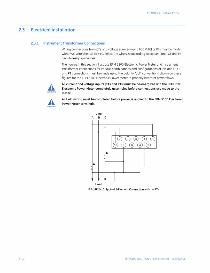
2.3.1 Instrument Transformer ConnectionsWiring connections from CTs and voltage sources (up to 600 V AC) or PTs may be made with AWG wire sizes up to #10. Select the wire size according to conventional CT and PT circuit-design guidelines.
The figures in this section illustrate EPM 5100 Electronic Power Meter and instrument transformer connections for various combinations and configurations of PTs and CTs. CT and PT connections must be made using the polarity “dot” conventions shown on these figures for the EPM 5100 Electronic Power Meter to properly interpret power flows.
All current and voltage inputs (CTs and PTs) must be de-energized and the EPM 5100 Electronic Power Meter completely assembled before connections are made to the meter.
All field wiring must be completed before power is applied to the EPM 5100 Electronic Power Meter terminals.
FIGURE 2–10: Typical 2-Element Connection with no PTs
WARNING
WARNING
A B C
Line
Load
10
9 3
6
5
2
7
8 4
1

CHAPTER 2: INSTALLATION
EPM 5100 ELECTRONIC POWER METER – USER GUIDE 2–11
FIGURE 2–11: Typical 2½-Element Connection with no PTs
FIGURE 2–12: Typical 3-Element Connections with no PTs
A B C
Line
Load
10
9 3
6
5
2
7
8 4
1
N
A B C
Line
Load
10
9 3
6
5
2
7
8 4
1
N

2–12 EPM 5100 ELECTRONIC POWER METER – USER GUIDE
CHAPTER 2: INSTALLATION
FIGURE 2–13: Typical 2-Element Connections for with Two PTs
Connections shown with a dotted line are optional and do not affect the performance of the meter if installed or removed. This allows use of any existing wiring configuration when retrofitting a GE DS-63 or DS-65 electromechanical watthour meter.
FIGURE 2–14: Typical 2½-Element Connections with Two PTs
A B C
Line
Load
10
9 3
6
5
2
7
8 4
1
NOTE
A B C
Line
Load
10
9 3
6
5
2
7
8 4
1
N

CHAPTER 2: INSTALLATION
EPM 5100 ELECTRONIC POWER METER – USER GUIDE 2–13
FIGURE 2–15: Typical 3-Element Connections with Three PTs
2.3.2 Pulse Initiation ConnectionsConnection to the optional pulse initiation circuits of the EPM 5100 is through the two three-point terminal points on the back of the case. The connection to these circuits, shown below, should be made at the same time as the current and voltage input connections.
Connection to the optional communication circuit of the EPM 5100 is through the six-position connector on the back of the case as indicated below.
A B C
Line
Load
10
9 3
6
5
2
7
8 4
1
N

2–14 EPM 5100 ELECTRONIC POWER METER – USER GUIDE
CHAPTER 2: INSTALLATION
FIGURE 2–16: Three-Point Terminal Blocks for Pulse Initiation Outputs

CHAPTER 2: INSTALLATION
EPM 5100 ELECTRONIC POWER METER – USER GUIDE 2–15
2.4 Communications Installation
2.4.1 Modbus ConnectionsThe following figure illustrates the connection points for Modbus communications which are made to the six-way connector. Dual connections are provided internal to the connector to assist in the provision of tee-connection capability.
FIGURE 2–17: Modbus Connections on the Six-Way Connector
The connection diagram above defines which pins support which network connection. Be very careful when considering Shield connections, since shields may perform several key functions within any given network topology. These functions, may include EMI shielding, ground referencing, and signal return path, when combined with the electrical characteristics of a specific installation, will determine how the shield may be most effectively used.
It should be noted that all pins of the six-way connector are electrically isolated from the EPM 5100 and, consequently, from the equipment in which the meter may be mounted. Also, pins 4 and 5 are connected internally to the communications card isolated ground.
For a comprehensive description of the Modbus communications register protocol implementation in the EPM 5100, refer to Chapter 5: Modbus Communications Features.
Do not use the Modbus communications option card with a version 2 EPM 5100 unless a “Modbus Compatible” label is present on the case and/or cradle. If no “Modbus Compatible” label is present, contact GE Multilin for details concerning the upgrade of the EPM 5100 to Modbus compatibility.
If this card is replacing a previous non-Modbus installation, ensure that all previous network wiring is removed before operation.
Under NO CIRCUMSTANCES should a Power Leader CNI card interconnection cable (catalog number PLCN12CG01) be connected to the six-way communications connector. SEVERE DAMAGE to the communications option card will result from such a connection.
2.4.2 Installation of the Communications CardThe following procedure describes the field installation of a communications option card into an existing EPM 5100. This procedure is unnecessary for a meter with a factory installed communication card.
Modbus + Shield
Shield
Modbus +
1
2
3
4
5
6
Modbus –
Modbus –
NOTE
WARNING
WARNING

2–16 EPM 5100 ELECTRONIC POWER METER – USER GUIDE
CHAPTER 2: INSTALLATION
Remove the grounding wrist strap from the envelope supplied with the communication option card.
Attach one end of the strap to a convenient, exposed, ground and the other end to your wrist, following the instructions on the envelope. Do not handle the communication card or touch any exposed electronics in the meter until the wrist strap is properly connected
Press the retaining tabs on both sides of the meter faceplate, illustrated in FIGURE 2–5: EPM 5100 Retaining Tabs on page 2–6, then pull the faceplate away from the meter, then down to remove. Support the faceplate specifically; do not pull the ribbon cable between the meter and faceplate. Do not let the faceplate hang by the ribbon cable.
Remove the connection plug at the bottom of the cradle to de-energize the EPM 5100.
Ensure that the meter is de-energized by verifying that the LCD panel is blank. Do not insert the communications option card until the meter is confirmed to be de-energized.
Remove the communication option card from the antistatic bag and position the card with the notched corner at the bottom right.
Insert the communication option card into the option card connector in the EPM 5100 by pressing the card into the connector at about a 300° angle, as illustrated below.
FIGURE 2–18: Positioning the Communications Card
When the right edge of the card is evenly seated in the option card connector, press the left edge of the card toward the meter until the retention latches click into place, as illustrated below. If the

CHAPTER 2: INSTALLATION
EPM 5100 ELECTRONIC POWER METER – USER GUIDE 2–17
card does not appear to be evenly seated or if both retention latches do not click into place, remove the card by spreading the retention latches away from the card, then repeat the installation.
FIGURE 2–19: Pressing the Communications Card into Place
Replace the connection plug into the slot at the bottom of the cradle.
Align the faceplate with the guides at the bottom of the meter, then gently press the faceplate up and toward the meter until the retaining tabs click through the guides in the faceplate, as illustrated in FIGURE 2–9: Aligning and Attaching the Faceplate on page 2–8.
Follow the instructions in Communications Values on page 4–12 to configure the communication network address.

2–18 EPM 5100 ELECTRONIC POWER METER – USER GUIDE
CHAPTER 2: INSTALLATION

EPM 5100 ELECTRONIC POWER METER – USER GUIDE 3–1
EPM 5100 Electronic Power Meter
Chapter 3: Metering
GE Consumer & IndustrialMultilin
Metering
3.1 Meter Operations
3.1.1 Meter Self-TestEach time that power is applied to the EPM 5100, it performs a self-test of its internal electronics. If there are no problems, the EPM 5100 displays the following message before entering into Metering mode:
If a critical failure is detected at self-test, the following message appears on the display:
When this message appears, the EPM 5100 will not continue normal operations.
The self-test can be run again by removing and reapplying power. If the same self-test failure message reappears, contact GE Multilin technical support.
3.1.2 Integrity of Metered ValuesThe self-test sequence also checks the integrity of the stored accumulated energy and metering values. If this test determines that some or all of the accumulated data are invalid, it displays either:
to indicate that less than 12 hours of energy data are lost, or
Self-Test OKData OK
POWER LEADER EPMSelf-Test Failed
Energy Data Loss

3–2 EPM 5100 ELECTRONIC POWER METER – USER GUIDE
CHAPTER 3: METERING
The EPM 5100 will continue with normal metering, with values displayed only on the second line. The error message remains displayed until the error is cleared (see Section 4-3 for a description of the error-clearing function).
During normal operation, if phase B or phase C voltage inputs are less than 25% of the rated value, the meter displays one of the following three messages:
The EPM 5100 continues with normal metering, with values displayed only on the second line. Note that Phase B is not applicable in a two-element delta configuration, and a 25% nominal voltage input on Phase A is outside of the EPM 5100 physical specifications, as shown in Specifications on page 1–13.
3.1.3 Communications ErrorIf the optional Modbus card is installed, the EPM 5100 indicates loss of communications by displaying the message
The EPM 5100 continues normal metering using only the second display line. If two or more of these error messages are active at the same time, the messages alternate on the top display line.
3.1.4 Display of Metered ValuesAfter self-test, the EPM 5100 enters metering mode and displays the values of selected line parameters. The EPM 5100 can be configured to either automatically or manually scroll through the metered parameters on the display. In addition, the duration that each parameter is displayed in automatic mode can be programmed. See Chapter 4 for details.
There are two separate lists of parameters that can be viewed, the normal and alternate scrolls. Metered parameter names and values are displayed on the LCD for the normal and alternate scroll in Table 1–2: EPM 5100 Metered Functions (ctd.) on page 1–4.
3.1.5 Keypad FunctionsPress the ↵ button to toggle the display between the two lists of parameters, the normal scroll and the alternate scroll.
The two SCROLL keys can be used at any time to scroll up or down the list of metered parameters, in the order given in Table 1–2: EPM 5100 Metered Functions (ctd.) on page 1–4, whether the EPM 5100 is in manual or automatic mode. If the meter is configured for automatic scrolling mode, it resumes one minute after the last scroll key press.
All Energy Lost
Phase Loss V B Phase Loss V C Phase Loss V BC
Comm Error

CHAPTER 3: METERING
EPM 5100 ELECTRONIC POWER METER – USER GUIDE 3–3
The first press of any key while the EPM 5100 is in Metering mode illuminates the backlit display, if it is not already lit . The display remains illuminated for 10 minutes after the last key press.
3.1.6 Metering AccuraciesThe EPM 5100 samples each of the voltage and current inputs 480 times per second to calculate the values of the parameters listed in Table 1–2: EPM 5100 Metered Functions (ctd.) on page 1–4. The meter automatically scales the units and displays the results on the LCD. The display is updated every three seconds. An example of a metering screen is shown below. The metering accuracies for all functions are listed in the following table.
FIGURE 3–1: Sample Metering Screen
Table 3–1: Metering Accuracies
Function Accuracy
Current (rms) ±0.25% of reading
Neutral current ±1.50% of reading
L-N voltage (rms) ±0.25% of reading
L-L voltage (rms) ±0.75% of reading
Watts ±0.5% of reading
Volt-amperes ±0.5% of reading
Power factor ±1.0% of reading
Energy ±0.5% of reading
Frequency ±0.5% of reading

3–4 EPM 5100 ELECTRONIC POWER METER – USER GUIDE
CHAPTER 3: METERING
3.2 Wye Configuration Metering Functions
3.2.1 DescriptionFollowing are descriptions of each of the metered values and status parameters available with the EPM 5100 in a wye configuration. Note that prefixes such as k or M depend on configuration, as described in Chapter 4. The suffixes A, B, C, and N generally refer to phase A, phase B, phase C, and neutral, respectively.
3.2.2 Current (rms)The EPM 5100 measures the current flowing in each line and determines the rms value. The meter displays the CT primary current, with a dynamic range up to 500 kA, depending on the CT ratio. Neutral current is calculated from the line values. Line and neutral current values are identified on the LCD as “A A”, “A B”, “A C”, and “A N”.
3.2.3 Voltage
Line-to-Neutral Voltage (rms)
The EPM 5100 measures either the line-to-neutral voltage inputs directly for inputs up to the rated voltage (69 to 600 V AC, as ordered) or from PTs for voltages above the rated voltage. The dynamic range is up to the rated voltage at the inputs, or 1200 kV of the PT primary voltage, depending on the PT ratio. Line-to-neutral voltages are identified on the LCD as “V AN”, “V BN”, and “V CN”.
Line-to-Line Voltage (rms)
The EPM 5100 measures the line-to-line voltages directly for inputs up to the rated voltage (69 to 600 V AC, as ordered) or from two or three line-to-line or line-to-neutral PTs for voltages above the rated voltage. The dynamic range is up to the rated voltage at the inputs, or 1200 kV of the PT primary voltage, depending on the PT ratio. Voltage line-to-line values are identified on the LCD as “V AB”, “V BC”, and “V CA”.
3.2.4 Power
Real Power
The real power is measured for each phase and for the total. Reverse power readings (load to line) are displayed as zero. Power values are identified on the LCD as “W A”, “W B”, “W C”, and “W”.
Reactive Power
The reactive power is calculated for each phase and for the total. Values are identified on the LCD as “Var A”, “Var B”, “Var C”, and “Var”.

CHAPTER 3: METERING
EPM 5100 ELECTRONIC POWER METER – USER GUIDE 3–5
3.2.5 Apparent PowerVoltamperes are calculated for each phase according to the following formula:
(EQ 3.1)
For total VA, the displayed “W” is equal to “W A” + “W B” + “W C” and the displayed “Var” is equal to “Var A” + “Var B” + “Var C”. Values are identified on the LCD as “VA A”, “VA B”, “VA C”, and “VA”.
3.2.6 EnergyEnergy is the summation of power over time and is provided as watthours, voltamperehours, Q-hours and lagging and leading varhours. The values are reset manually in Program mode or automatically when the maximum value that can be displayed on the LCD is exceeded. Values are identified on the LCD as Wh, VAh, Qh, +Varh (lagging), and -Varh (leading).
3.2.7 FrequencyThe frequency calculated by the EPM 5100 is identified on the LCD as Hertz.
3.2.8 Demand
Current Demand (Present Ampere Demand)
Current demand is the average rms current metered over the previous demand interval. The demand interval may be set to 15, 20, 30, or 60 minutes, with rolling demand subintervals of 5, 10, 15, 20, and 30 minutes (depending on the main interval length). Values are identified on the LCD as “A ADmd”, “A BDmd”, and “A CDmd”.
Peak Current Demand (Maximum Ampere Demand)
Peak current is the maximum current demand recorded since the demand values were last reset. Values are identified on the LCD as “A APk”, “A BPk”, and “A CPk”.
Present Power Demand
Present power demand is given as watts, voltamperes, and lagging (+) and leading (–) vars metered over the most recently completed demand interval. The demand interval may be set as described under Current Demand above. Values are identified on the LCD as “W Dmd”, “VA Dmd”, “+VarDmd”, and “–VarDmd”.
Peak Power Demand
Peak power is given as the maximum watts, voltamperes, and lagging (+) and leading (–) vars demands recorded since the demand values were last reset. Values are identified on the LCD as “W Peak”, “VA Pk”, “+Var Pk”, and “–Var Pk”.
Apparent power (VA) Real Power( )2 Reactive Power( )2+=

3–6 EPM 5100 ELECTRONIC POWER METER – USER GUIDE
CHAPTER 3: METERING
3.2.9 Power Factor
Power Factor
Power factor is calculated for each phase and for the total. With no input voltage or current, power factor values are displayed as 0.00. Values are identified on the LCD as “PF A”, “PF B”, “PF C”, and “PF”, with an appropriate indication for lagging (LAG) or leading (LEAD) current with respect to voltage.
Average Power Factor
Average power factor is given for the previous demand interval (DmdAvg) and also for the entire period since the last demand reset (Avg). The demand interval may be set as described under Current Demand above. Values are identified on the LCD as “PF DmdAvg” and “PF Avg”.
Power Factor and Watts at Maximum Voltamperes
The power factor and real power demand that occurred at the same time as the maximum recorded voltampere demand value since the last demand reset are displayed. Values are identified on the LCD as “PF@VAPk” and “W@VAPk”.
3.2.10 Miscellaneous FunctionsThe number of times the demand values were reset since the last meter initialization is identified on the LCD as “Dmd Reset”. The time left in the present demand subinterval is identified as “Dsub time”. The number of power outages encountered since the last meter initialization is identified as “Power Out”.
3.2.11 Transformer RatiosThe potential transformer (PT) and current transformer (CT) ratios are identified on the LCD as “PTR” and “CTR”, respectively.

CHAPTER 3: METERING
EPM 5100 ELECTRONIC POWER METER – USER GUIDE 3–7
3.3 Delta Configuration Metering Functions
3.3.1 DescriptionFollowing are descriptions of each of the metered values and status parameters available with the EPM 5100 in a delta configuration. Note that prefixes such as k or M depend on configuration, as described in Chapter 4. The suffixes A, B, and C generally refer to phase A, phase B, and phase C, respectively.
3.3.2 Current (rms)The EPM 5100 measures the current flowing in each phase and determines the rms value. The meter displays the CT primary current, with a dynamic range up to 500 kA, depending on the CT ratio. Phase currents are calculated from the line values and are identified on the LCD as “A A”, “A B”, and “A C”.
3.3.3 Line-to-Line Voltage (rms)The EPM 5100 measures phases A and C line-to-line voltages directly for inputs up to the rated voltage (69 to 600 V AC, as ordered) or from two line-to-line PTs for voltages above the rated voltage. The dynamic range is up to the rated voltage at the inputs, or 1200 kV of the PT primary voltage, depending on the PT ratio. Voltage line-to-line values are identified on the LCD as “V AB”, “V BC”, and “V CA”.
3.3.4 Power
Real Power
The real power is measured for phases A and C and for the total. Reverse power readings (load to line) are displayed as zero. Power values are identified on the LCD as “W AB”, “W BC”, and “W”.
Reactive Power
The reactive power is calculated for phases A and C and for the total. Values are identified on the LCD as “Var AB”, “Var BC”, and “Var”.
Apparent Power
Voltamperes are calculated for each phase according to the following formula:
(EQ 3.2)
For total VA on 2-element delta, the displayed “W” is equal to “W AB” + “W BC” and the displayed “Var” is equal to “Var AB” + “Var BC”. Values are identified on the LCD as “VA AB”, “VA BC”, and “VA”.
Apparent power (VA) Real Power( )2 Reactive Power( )2+=

3–8 EPM 5100 ELECTRONIC POWER METER – USER GUIDE
CHAPTER 3: METERING
3.3.5 EnergyEnergy is the summation of power over time and is provided as watthours, voltamperehours, Q-hours and varhours. The values are reset manually in Program mode or automatically when the maximum value that can be displayed on the LCD is exceeded. Values are identified on the LCD as “Wh”, “VAh”, “Qh”, “+Varh” (lagging) and “–Varh” (leading).
3.3.6 FrequencyThe frequency calculated by the EPM 5100 is identified on the LCD as “Hertz”.
3.3.7 Demand
Current Demand (Present Ampere Demand)
Current demand is the average rms current metered over the previous demand interval. The demand interval may be set to 15, 20, 30, or 60 minutes, with rolling demand subintervals of 5, 10, 15, 20, and 30 minutes (depending on the main interval length). Values are identified on the LCD as “A ADmd” and “A CDmd”. Note that this function is not available for phase B current.
Peak Current Demand (Maximum Ampere Demand)
Peak current is the maximum current demand recorded since the demand values were last reset. Values are identified on the LCD as “A APk” and “A CPk”. Note that this function is not available for phase B current.
Present Power Demand
Present power demand is given as watts, voltamperes, and lagging (+) and leading (–) vars metered over the most recently completed demand interval. The demand interval may be set as described under Current Demand above. Values are identified on the LCD as “W Dmd”, “VA Dmd”, “+VarDmd”, and “–VarDmd”.
Peak Power Demand
Peak power is given as the maximum watts, voltamperes, and lagging (+) and leading (–) vars demands recorded since the demand values were last reset. Values are identified on the LCD as “W Peak”, “VA Pk”, “+Var Pk”, and “–Var Pk”.
3.3.8 Power Factor
Power Factor
Power factor is calculated for phases A and C and for the total. With no input voltage or current, power factor values are displayed as 0.00. Values are identified on the LCD as “PF AB”, “PF BC”, and “PF”, with an appropriate indication for lagging (LAG) or leading (LEAD) current with respect to voltage.

CHAPTER 3: METERING
EPM 5100 ELECTRONIC POWER METER – USER GUIDE 3–9
Average Power Factor
Average power factor is given for the previous demand interval (DmdAvg) and also for the entire period since the last demand reset (Avg). The demand interval may be set as described under Current Demand above. Values are identified on the LCD as “PF DmdAvg” and “PF Avg”.
Power Factor and Watts at Maximum Voltamperes
The power factor and real power demands that occurred in the same demand period as the maximum recorded voltampere demand value since the last demand reset are displayed. Values are identified on the LCD as “PF@VAPk” and “W@VAPk”.
3.3.9 Miscellaneous FunctionsThe number of times the demand values were reset since the last meter initialization is identified on the LCD as “Dmd Reset”. The time left in the present demand subinterval is identified as “Dsub time”. The number of power outages encountered since the last meter initialization is identified as a “Power Out”.
3.3.10 Transformer RatiosThe potential transformer (PT) and current transformer (CT) ratios are identified on the LCD as “PTR” and “CTR”, respectively.

3–10 EPM 5100 ELECTRONIC POWER METER – USER GUIDE
CHAPTER 3: METERING

EPM 5100 ELECTRONIC POWER METER – USER GUIDE 4–1
EPM 5100 Electronic Power Meter
Chapter 4: Programming
GE Consumer & IndustrialMultilin
Programming
4.1 Program Mode
4.1.1 IntroductionThe EPM 5100 is configured to the application requirements in Program mode. This mode is also used to reset stored demand and energy values and to clear errors. Press the GE logo to activate the secret button and enter Program mode.
The EPM 5100 automatically returns to Metering mode from Program mode whenever no keypad entry has been made for five minutes.

4–2 EPM 5100 ELECTRONIC POWER METER – USER GUIDE
CHAPTER 4: PROGRAMMING
4.2 Access to Program Functions
4.2.1 OverviewThe top-level main menu in Program mode displays:
The functions available in the Program mode main menu appear on the second line and are:
Data Resetting →Data Formatting →Comm Addr SetupKYZ Pulse Setup →Configuration →Restricted Area →Serial & Rev #sMeter TypeExit
The figure below shows the display on entry to Program Mode.
FIGURE 4–1: Example Display on Entry to Program Mode.
Press the and keys to scroll through the list of functions. When the desired function is displayed, press ↵ to access the list of options available for that function. Press the and
keys to scroll through the list to the desired option, then press ↵ to select it . Scroll to Exit and press ↵ to return to the main menu from an options list or to Metering Mode from the main menu.
When either of the “Data Formatting”, “Comm Addr Setup”, “KYZ Pulse Setup”, or “Configuration” functions is active, metering stops until control returns to the main menu. In addition, a return to the main menu from these functions automatically resets the demand interval time period. The other functions have no effect on metering.
PROGRAMMING MENU

CHAPTER 4: PROGRAMMING
EPM 5100 ELECTRONIC POWER METER – USER GUIDE 4–3
4.2.2 Restricted AccessAccess to any of the Program mode functions, except “Restricted Area”, “Serial & Rev #s”, “Meter Type”, and “Exit”, may be restricted through the Access Restrict menu. If all other functions have been restricted, these four are the only initial choices. Note that the Access Restrict menu provides a way to prevent entry into the Program mode functions that temporarily stop normal metering.
To gain access to restricted functions, scroll to:
Pressing ↵ changes the display as follows:
Enter the first digit of the password with the and keys, press ↵, enter the second digit, press ↵, and so on until all six digits are entered, as illustrated below (the factory default password is 00-00-00).
FIGURE 4–2: Entering the Password
After the sixth digit has been entered correctly, the display returns to the main menu, with the sequence:
Data Resetting →Data Formatting →Comm Addr SetupKYZ Pulse Setup →Configuration →Access Restrict →New Password?Serial & Rev #sMeter TypeExit
The display returns to the previous menu if the password is not entered correctly.
Restricted Area→
Match password:00-00-00

4–4 EPM 5100 ELECTRONIC POWER METER – USER GUIDE
CHAPTER 4: PROGRAMMING
4.2.3 Exiting Program ModeEach of the functions available in Program mode is described in this chapter. To return at any time to Metering mode, press the secret button (under the GE logo) or scroll to
and press ↵. Note that the latter method may have to be repeated to completely leave Program mode.
Exit
CHAPTER 4: PROGRAMMING
EPM 5100 ELECTRONIC POWER METER – USER GUIDE 4–5
4.3 Data Resetting
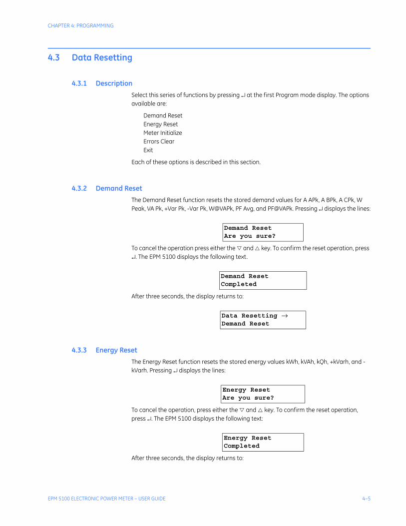
4.3.1 DescriptionSelect this series of functions by pressing ↵ at the first Program mode display. The options available are:
Demand ResetEnergy ResetMeter InitializeErrors ClearExit
Each of these options is described in this section.
4.3.2 Demand ResetThe Demand Reset function resets the stored demand values for A APk, A BPk, A CPk, W Peak, VA Pk, +Var Pk, -Var Pk, W@VAPk, PF Avg, and PF@VAPk. Pressing ↵ displays the lines:
To cancel the operation press either the and key. To confirm the reset operation, press ↵. The EPM 5100 displays the following text.
After three seconds, the display returns to:
4.3.3 Energy ResetThe Energy Reset function resets the stored energy values kWh, kVAh, kQh, +kVarh, and -kVarh. Pressing ↵ displays the lines:
To cancel the operation, press either the and key. To confirm the reset operation, press ↵. The EPM 5100 displays the following text:
After three seconds, the display returns to:
Demand ResetAre you sure?
Demand ResetCompleted
Data Resetting →Demand Reset
Energy ResetAre you sure?
Energy ResetCompleted

4–6 EPM 5100 ELECTRONIC POWER METER – USER GUIDE
CHAPTER 4: PROGRAMMING
4.3.4 Meter InitializeThe Meter Initialize function resets all counters and accumulated energy and starts a new demand period (user-defined configurations and data formatting are not affected). Pressing ↵ displays the lines
To cancel the operation press either the and key. To confirm the initialize operation, press ↵. The EPM 5100 displays the following text:
After three seconds, the display returns to:
4.3.5 Errors ClearThe Errors Clear function clears any existing error messages. Pressing ¿ displays the lines
To cancel the operation press either the and key. To confirm the clear operation, press ↵. The EPM 5100 displays the following text:
After three seconds, the display returns to:
Data Resetting →Energy Reset
Meter InitializeAre you sure?
Meter InitializeCompleted
Data Resetting →Meter Initialize
Errors ClearAre you sure?
Errors ClearCompleted
Data Resetting →Errors Clear

CHAPTER 4: PROGRAMMING
EPM 5100 ELECTRONIC POWER METER – USER GUIDE 4–7
4.4 Data Formatting
4.4.1 OverviewThe options available under the Data Formatting function are:
Normal ScrollAltrn. ScrollEnergy FormatDemand FormatVolt FormatAmp FormatLeading ZerosScroll TimeExit
Each of these options is described in this section.
4.4.2 Normal ScrollPress ↵, then use the and keys to display the list of metered and calculated parameters available with the normal scroll as shown in the following table.
The pound sign (#) in the first display position means that the parameter will be displayed in the normal scroll sequence. To remove a parameter from the default (or to add one that is presently off), press ↵. A space in the first position means that the parameter will not be displayed in the normal scroll sequence. The figures below illustrate a metering function with the pound sign displayed and the same function with the pound sign removed.
FIGURE 4–3: Typical Scroll Sequence Display

4–8 EPM 5100 ELECTRONIC POWER METER – USER GUIDE
CHAPTER 4: PROGRAMMING
FIGURE 4–4: Typical Non-Scroll Sequence Display
Table 4–1: Parameters Available with Normal Scroll
2½ and 3 element Wye 2 element Delta
# A A # A A
# A B # A B
# A C # A C
# A N # V AB
# V AN # V BC
# V BN # V CA
# V CN # W AB
# V AB # W BC
# V BC # W
# V CA # W Dmd
# W A # W Peak
# W B # Var AB
# W C # Var BC
# W # Var
# W Dmd # VA AB
# W Peak # VA BC
# Var A # VA
# Var B # PF [Lag or Lead]
# Var C # kWh
# Var # +kVarh
# VA A # -kVarh

CHAPTER 4: PROGRAMMING
EPM 5100 ELECTRONIC POWER METER – USER GUIDE 4–9
4.4.3 Energy FormatPress ↵ to show the format for displaying energy values. The energy format is displayed as follows:
The second line shows the active format and the cursor appears under the fifth position, after the first four X's. Either the and key toggles that character among X, period (.), or blank. If X is chosen by pressing ↵, the cursor moves over one position and the same choices may be made; if period is chosen, only X and blank are available at the next position. Choosing a blank at any position jumps the cursor to the units multiplier, which toggles between 'k' (kilo) or 'M' (mega). Press ↵ one more time to confirm your choice. The available formatting choices are
XXXXXXXX.XXXXX.XXXXXXXXXXXX.XXXXXXX
4.4.4 Demand FormatPress ↵ to show the format for displaying demand values:
The second line shows the active format and the cursor appears under the fourth position, after the first three X's. Either the and key toggles that character among X, period (.), or blank. If X is chosen by pressing ↵, the cursor moves over one position and the same
# VA B # kVAh
# VA C # Hertz
# VA
# PF [Lag or Lead]
# kWh
# +kVarh
# -kVarh
# kVAh
# Hertz
Table 4–1: Parameters Available with Normal Scroll
2½ and 3 element Wye 2 element Delta
Energy Format:XXXX_ ’k’
Demand Format:XXX_ ’ ’

4–10 EPM 5100 ELECTRONIC POWER METER – USER GUIDE
CHAPTER 4: PROGRAMMING
choices may be made; if period is chosen, only X and blank are available at the next position. Choosing a blank at any position jumps the cursor to the units multiplier, which toggles among ' ', 'k' (kilo), or 'M' (mega). Press ↵ one more time to confirm your choice. The available formatting choices are
XXXXXX.XXXX.XXXXX.XXXXXXXXXXX.XXXXX.XXXXXXXXXXXX.XXXXXXX
4.4.5 Voltage FormatPress ↵ to show the format for displaying voltage values:
The voltage format is selected in the same way as the demand format, with the same choices available, except that M is not available as a units multiplier.
4.4.6 Current FormatPress ↵ to show the format for displaying current values:
The current format is selected in the same way as the voltage format, with the same choices available.
4.4.7 Leading ZerosThis function determines whether parameter values will be displayed with leading LCD positions filled with zeros. Press ↵ to display the two choices:
Scroll between the two options, then press ↵ to select your choice.
4.4.8 Scroll TimePress ↵ to display the time that each parameter is displayed during automatic scroll in Metering mode:
Volt Format:XXX_ ’ ’
Amp Format:XXX_ ’ ’
Leading Zeros:WITHOUT ZEROS
Leading Zeros:WITH ZEROS

CHAPTER 4: PROGRAMMING
EPM 5100 ELECTRONIC POWER METER – USER GUIDE 4–11
Use the and key to select the desired value, press ↵ to select the units position, scroll to the desired value and press ↵ to confirm. The default is 10 seconds.
Set the scroll time to “00” to set the metering display to manual mode. In this mode, the and keys must be used to change the displayed parameter.
Scroll Time:10 second(s)

4–12 EPM 5100 ELECTRONIC POWER METER – USER GUIDE
CHAPTER 4: PROGRAMMING
4.5 Communications Values
4.5.1 Communication Address SetupUse a small screwdriver to set the most significant digit of the Modbus address by setting switch S1 to the required digit in the range 0 to 9, as illustrated in the figure below. Repeat this operation for the middle digit of the address by adjustment of switch S2 and for the least significant digit of the address by adjustment of switch S3.
Modbus addresses are valid only in the range 33 to 247. Setting the address outside this range will terminate response of the device to the Modbus network.
FIGURE 4–5: Modbus Address Setup
4.5.2 Baud Rate SetupAdjust sliders 3 and 4 (refer to the figure above) as indicated below for compatibility with the operating baud rate of the network:
NOTE
ON
1 2 3 4
S2
S3
S4
8
2 3
9
456
7
10
S1
8
2 3
9
45
67
10
8
2 3
9
45
67
10
Table 4–2: Baud Rate Setup
Baud Rate Slider 3 Slider 4
1200 ON ON
2400 OFF ON
9600 ON OFF
19200 OFF OFF

CHAPTER 4: PROGRAMMING
EPM 5100 ELECTRONIC POWER METER – USER GUIDE 4–13
4.5.3 EPM Compatibility SetupThe Modbus RTU Option Card, catalog number PLA3CMAG01, is compatible with GE ED&C host products in addition to the EPM 5100. For specific operation with the EPM 5100 it is necessary to select the compatible operating mode by switch settings on the communications option card. Use a small screwdriver adjust sliders 1 and 2 of switch S4 (refer to the figure above) as follows:
Slider 1: ONSlider 2: ON

4–14 EPM 5100 ELECTRONIC POWER METER – USER GUIDE
CHAPTER 4: PROGRAMMING
4.6 Pulse Outputs
4.6.1 Pulse Output SetupThis function appears only if the pulse initiation option was ordered with the EPM 5100. There are two pulse initiation output channels that are set up with this function. The options available are:
Output 1Output 2Exit
Selecting Output 1 with the ↵ key displays the setting:
Move through the setting positions with ↵, then set the desired value with the and keys. When the weight has been set, press ↵ to advance to the energy units, then choose among kVAh, kWh, kVarh, and kQh. Confirm your choice by pressing ↵.
This setting defines the incremental energy usage level at which pulses are transmitted from the output. For instance, if kWh is selected with a pulse weight of 0.15, as illustrated below, then a pulse is sent for each 150 watthours of energy consumed.
FIGURE 4–6: KYZ Pulse Weight Setup Display
Press ↵ to return to the KYZ Pulse Setup menu. Follow the same procedure to setup Output 2.
4.6.2 Upgrading from Electromechanical MetersWhen upgrading from an electromechanical watthour meter with pulse initiation to the EPM 5100 with pulse initiation, a mathematical conversion is required to obtain the proper value for programming the meter. The formula is:
(EQ 4.1)
KYZ1 Pulseweight:000.000000 kVAh
Disk revolution per pulse1000Ke
PT ratio( ) CT ratio( )Kh-------------------------------------------------------=

CHAPTER 4: PROGRAMMING
EPM 5100 ELECTRONIC POWER METER – USER GUIDE 4–15
To use this equation, insert the known quantities from the present installation and the constant, Kh, from the table below, then solve for Ke to program the EPM 5100. An example follows the table.
4.6.3 Upgrade Calculation ExampleFor example, a customer has a 480/277 V system (3 phase, 4-wire) with a 1600 A main. The watthour meter with pulse initiation is being replaced with a EPM 5100. The watthour meter was set for one pulse every ¼-disk revolution. The value to be programmed into the meter is calculated as follows:
(EQ 4.2)
Therefore, 0.6912 kWh or 6912 watthours should be programmed into the EPM 5100.
Table 4–3: Values of Kh for Pulse Initiation
Voltage System Kh
69 V 4Y 1.08
120 V 34Y
1.21.8
240 V 34Y
2.43.6
277 V 4Y 3.6
480 V 3 4.8
600 V 3 6.0
Disk revolution per pulse1000Ke
PT ratio( ) CT ratio( )Kh-------------------------------------------------------=
1 4⁄1----------
1000Ke
280 120⁄( ) 1600 5⁄( ) 3.6×------------------------------------------------------------------=⇒
14---
1000Ke
2764.8------------------=⇒
1000Ke 691.2=⇒
Ke 0.6912 kWh=⇒

4–16 EPM 5100 ELECTRONIC POWER METER – USER GUIDE
CHAPTER 4: PROGRAMMING
4.7 Configuration
4.7.1 OptionsThe options available with the Configuration function are:
PT RatioCT RatioDemand Period SetupMeter TypeExit
Each of these options is described below.
4.7.2 PT RatioThe potential transformer ratio is obtained by dividing the PT primary voltage by the EPM 5100 input voltage rating:
(EQ 4.3)
For instance, if 480 V AC PTs are installed in a 120 V meter, enter “4.0” in the display. If PTs are not used, the proper ratio is 1.0 (the default setting).
Selecting this option produces the display:
Press ↵ to move to the right across the display, entering values in the appropriate positions with the and keys. When the desired value is entered, continue pressing ↵ to return to the Configuration menu.
4.7.3 CT RatioThe current transformer ratio is obtained by dividing the CT current rating by 5 A:
(EQ 4.4)
For instance, if 1000 A CTs are installed, enter “200.0” in the display.
Selecting this option produces the display
Press ↵ to move to the right across the display, entering values in the appropriate positions with the and keys. When the desired value is entered, continue pressing ↵ to return to the Configuration menu.
P.T. Ratio:0001.00000
PT Ratio PT Primary VoltageEPM Input Voltage Rating---------------------------------------------------------------=
C.T. Ratio:00001.00000
CT Ratio CT Primary Current Rating5 A
-----------------------------------------------------------------=

CHAPTER 4: PROGRAMMING
EPM 5100 ELECTRONIC POWER METER – USER GUIDE 4–17
4.7.4 Demand Period SetupThe demand period is set with the display shown in the following figure.
FIGURE 4–7: Demand Period Setup Display
Set the desired block (Blk=) demand period and the subinterval (Sub=) for rolling demand calculations with the and keys. Press ↵ to return to the Configuration menu.
The EPM 5100 automatically adjusts the subinterval time choices according to the demand interval chosen. The available choices are listed below.
4.7.5 Meter TypeThe EPM 5100 offers the following meter type configurations:
3 Element Wye2.5 Element Wye2 Element Delta
Scroll to the entry corresponding to the correct setup and select it with ↵.
The configurations that are actually available depend on the input voltage. See Order Codes on page 1–11 for the list of available configurations.
Table 4–4: Demand Subintervals
Block Interval Available Subintervals
15 min. 5, 15 min.
20 min. 5, 10, 20 min.
30 min. 5, 10, 15, 30 min.
60 min. 10, 15, 20, 30, 60 min.

4–18 EPM 5100 ELECTRONIC POWER METER – USER GUIDE
CHAPTER 4: PROGRAMMING
4.8 Restricted Access Functions
4.8.1 Access RestrictThis function only appears if the password has been correctly entered. Each of the functions in the Configuration menu may be restricted so that the function only becomes available after the password has been correctly entered. The options available under the Access Restrict menu are:
Data Resetting?Data Formatting?KYZ Pulse Setup?Configuration?Comm Addr Setup?Demand Reset?Energy Reset?Meter Init?Errors Clear?Exit
Move through the list with the and keys, select any of the options with ↵, then scroll between
UnprotectedProtected
Select the desired choice with ↵.
4.8.2 New PasswordThis function is only available after the password has been correctly entered. To change the password, press ↵ to display:
Note that the current active password is displayed in place of the zeros. Use the and keys to enter the desired digit in first position, then press ↵ to move to the second position. Continue until all six digits have been entered, after which the display returns to the New Password menu.
New Password:00-00-00

CHAPTER 4: PROGRAMMING
EPM 5100 ELECTRONIC POWER METER – USER GUIDE 4–19
4.9 Default Settings
4.9.1 DescriptionThe following table lists the default settings for the EPM 5100 as shipped.
Table 4–5: EPM 5100 Default Settings
Parameter Default Setting
Energy Format XXXXX.X K
Demand Format XXXXXX
Voltage Format XXXX.X
Current Format XXXX.XX
Leading Zeros WITHOUT ZEROS
KYZ1 Pulseweight 000.000000 kVAh
KYZ2 Pulseweight 000.000000 kVAh
PT Ratio 1.000000
CT Ratio 1.000000
Demand Interval 15 (Minutes)
Demand Subinterval 5 (Minutes)
Scroll Time 10 seconds
Password 00-00-00

4–20 EPM 5100 ELECTRONIC POWER METER – USER GUIDE
CHAPTER 4: PROGRAMMING

EPM 5100 ELECTRONIC POWER METER – USER GUIDE 5–1
EPM 5100 Electronic Power Meter
Chapter 5: Communications
GE Consumer & IndustrialMultilin
Communications
5.1 Introduction
5.1.1 OverviewThe tables in this chapter indicate the event codes and register maps of the EPM 5100. This section is intended only as a guide to the functions available with the device.
5.1.2 EventsEvents describe specific status conditions within the device and are available to the host computer either through the special DDE item, Events, or by direct read access of the registers containing the event information.
The following table defines the events supported by the EPM 5100.
Table 5–1: EPM 5100 Events
Event code
(decimal)
Meaning Register 1 Register 5
256 Voltage Phase Loss LSB -Voltage Loss Phase N/A
512Internal Communication Error
N/A
B0:Old Data, data from device is not up to dateB1:Busy Flag, Previously commanded transaction still in progressB5:Data Not Ready, the first full set of data is not yet acquired by the deviceRemaining Bits: Unused

5–2 EPM 5100 ELECTRONIC POWER METER – USER GUIDE
CHAPTER 5: COMMUNICATIONS
5.1.3 Modbus Register MapsThe register map for the EPM 5100 are illustrated below. These tables list the registers that may be accessed by the host computer over the Modbus network.
The registers are divided into four sections:
1. Fixed value registers (addresses R40000 to R40009)
2. Dynamic values registers (addresses R31000 to R31118)
3. Setpoint registers (addresses R43000 to R43032)
4. Command coils (addresses R00000 to R00003)
The fixed value registers contain information relating to parameters that are either factory set and cannot be changed by the user or can only be changed via the faceplate of the EPM 5100. The contents of these registers do not vary during the operation of the device.
513Internal Communication Restored
N/A
B0:Old Data, data from device is not up to dateB1:Busy Flag, Previously commanded transaction still in progressB5:Data Not Ready, the first full set of data is not yet acquired by the deviceRemaining Bits: Unused
520 Configuration Change N/A Address of changed Setpoint
522 Address Conflict Detected N/A N/A
543 Hardware Failure/BIT Failure N/A
B3:A/D Converter FailureB2: NVM FailureB1: ROM FailureB0: RAM Failure
578 Remote SetPoint Change Failed N/A N/A
579 Partial Energy Loss Error N/A N/A
580 Complete Energy Loss Error N/A N/A
581 Meter Errors Cleared Locally N/A N/A
582 Meter Initialized Locally N/A N/A
583 Demand Reset Locally N/A N/A
585 Unspecified General Failure N/A N/A
Table 5–1: EPM 5100 Events
Event code
(decimal)
Meaning Register 1 Register 5

CHAPTER 5: COMMUNICATIONS
EPM 5100 ELECTRONIC POWER METER – USER GUIDE 5–3
The dynamic value registers contain information relating to variable operating parameters such as phase current and phase voltage. These registers are read-only and their contents cannot be changed by the user.
The setpoint registers contain information that configures the device to operate in a user-defined manner. These registers may be read over the modbus network, but may not be written over the network. Any changes to the setpoint registers can only be made via the faceplate.
The command coils (registers) allow you to cause specific control actions to take place at the device, such as Clear Energy Accumulators.
Addresses designated with L suffix return a Long Signed Integer value concatenated from two successive registers. Addresses designated with F suffix return a floating point value concatenated from two successive registers. Addresses designated with Ann suffix return an array read from nn successive registers.
NOTE
Table 5–2: Modbus Memory Map (Sheet 1 of 3)Register Mnemonic Contents Range / Units R/W Format
Command Coils
R00000 CLEAR_DMND Clear power demand (watts) 0 to 1 WO F17
R00001 MTR_INITIALIZE Initialize meter 0 to 1 WO F17
R00002 CLEAR_ENERGY Clear energy (var-hour) 0 to 1 WO F17
R00003 CLEAR_ERROR Clear meter errors 0 to 1 WO F17
Dynamic Value Registers
R31000 PENDING_EVENTS Number of pending event messages 0 to 8 RO F1
R31002F KVA_MAX_TOTAL kVA max, total of all phases kVA RO F4
R31004F KW_MAX_TOTAL kW max, total of all phases kW RO F4
R31006F KVAR_LG_MAX_TOTAL kvar lag max, total of all phases kvar RO F4
R31008F KVAR_LD_MAX_TOTAL kvar lead max, total of all phases kvar RO F4
R31010F AMPS_MAX_A Current Max Phase A amps RO F4
R31012F AMPS_MAX_B Current Max Phase B amps RO F4
R31014F AMPS_MAX_C Current Max Phase C amps RO F4
R31016F KVARH_LG_TOTAL kvarh lag, total of all phases kVARh RO F4
R31018F KVARH_LD_TOTAL kvarh lead, total of all phases kVARh RO F4
R31020F KWH_TOTAL kWh, total of all phases kWh RO F4
R31022F KQH_TOTAL kQh, total of all phases kqhQ = ( x var + W) / 2 RO F4
R31024F KVAH_TOTAL kVAh, total of all phases kVAh RO F4
R31026F PF_AVG Average power factor since last reset, all phases --- RO F4
R31028F PF_AT_KVA_MAX Power factor, total of all phases, at maximum kVA --- RO F4
R31030F KVA_DMND_TOTAL Apparent power demand (kVA), total of all phases kVA RO F4
R31032F KW_DMND_TOTAL Real power demand (kW) total of all phases kW RO F4
R31034F KVAR_LG_DMND_TOTAL Reactive power demand (kvar lag), total of all phases kvar RO F4
R31036F KVAR_LD_DMND_TOTAL Reactive power demand (kvar lead), total of all phases kvar RO F4
R31038F AMPS_DMND_A Current demand, phase A amps RO F4
R31040F AMPS_DMND_B Current demand, phase B amps RO F4
R31042F AMPS_DMND_C Current demand, phase C amps RO F4
R31044F PF_DMND Power factor, all phases (over last demand interval) --- RO F4
R31046F KW_A Real power (kW), phase A kW RO F4
R31048F KW_B Real power (kW), phase B kW RO F4
R31050F KW_C Real power (kW), phase C kW RO F4
R31052F KVAR_A Reactive power (kvar), phase A kvar RO F4
R31054F KVAR_B Reactive power (kvar), phase B kvar RO F4
R31056F KVAR_C Reactive power (kvar), phase C kvar RO F4
R31058F KVA_A Apparent power (kVA), phase A kVA RO F4
3

5–4 EPM 5100 ELECTRONIC POWER METER – USER GUIDE
CHAPTER 5: COMMUNICATIONS
R31060F KVA_B Apparent power (kVA), phase B kVA RO F4
R31062F KVA_C Apparent power (kVA), phase C kVA RO F4
R31064F PF_A Power factor, Phase A --- RO F4
R31066F PF_B Power factor, Phase B --- RO F4
R31068F PF_C Power factor, Phase C --- RO F4
R31070F KVA_TOTAL Apparent power (kVA), total of all phases kVA RO F4
R31072F KW_TOTAL Real power (kW), total of all phases kW RO F4
R31074F KVAR_TOTAL Reactive power (kvar), total of all phases kVAR RO F4
R31076F VOLTS_A L-N voltage, phase A-N volts RO F4
R31078F VOLTS_B L-N voltage, phase B-N volts RO F4
R31080F VOLTS_C L-N voltage, phase C-N volts RO F4
R31082F VOLTS_AB L-L voltage, phase A-B volts RO F4
R31084F VOLTS_BC L-L voltage, phase B-C volts RO F4
R31086F VOLTS_CA L-L voltage, phase C-A volts RO F4
R31088F PF Total power factor of all phases --- RO F4
R31090F KW_TOTAL_AT_KVA_MAX Real power (KW), total of all phases at maximum kVA kW RO F4
R31092F AMPS_A Current, phase A amps RO F4
R31094F AMPS_B Current, phase B amps RO F4
R31096F AMPS_C Current, phase C amps RO F4
R31098F AMPS_N Neutral current amps RO F4
R31100F FREQUENCY Frequency Hz RO F4
R31102 TIME_LEFT Time left in demand interval seconds RO F1
R31103 NO_OF_RESET Number of resets 0 to 255 RO F5
R31104 NO_OF_PWR_FAILS Number of power failures 0 to 255 RO F5
R31105 METER_ERROR Meter error flags --- RO F6
R31106 VOLTS_PHASE_ERR Voltage phase loss errors --- RO F7
R31107 LD_LG_PF_TOTAL Lead/lag qualifier for all phases (instantaneous) 0 to 1 RO F8
R31108 LD_LG_PF_A Lead/Lag qualifier for phase A (instantaneous) 0 to 1 RO F8
R31109 LD_LG_PF_B Lead/Lag qualifier for phase B (instantaneous) 0 to 1 RO F8
R31110 LD_LG_PF_C Lead/Lag qualifier for phase C (instantaneous) 0 to 1 RO F8
R31111 DATA_RESET_FLAG Data Resetting flags --- RO F9
R31112F PREV_ACCUM_WH Previous Accumulated Wh Wh RO F4
R31114F PREV_ACCUM_VARH_LG Previous Accumulated varh lagging varh RO F4
R31116F PREV_ACCUM_VARH_LD Previous Accumulated varh leading varh RO F4
R31118 DATA_CLR_STATUS Data Cleared Status 0- Not Cleared1 - Cleared RO F10
Fixed Value Registers
R40000 PRODUCT_ID Product Id always 0Eh RO F1
R40002 --- Reserved --- --- ---
R40003 MODBUS_ADDR Modbus Address 33 to 215 RO F1
R40004L SERIAL_NUM Serial Number --- RO F2
R40006L SW_REV Firmware Revision 00.00 to 99.99 RO F3
R40008 COC_REV COC Software Revision --- RO F3
R40009 --- --- --- --- ---
Setpoint Value Registers
R43000 HOUR Hour 0 to 23 hrs. RW F1
R43001 MIN Minute 0 to 59 min. RW F1
R43002 SEC Seconds 0 to 59 sec. RW F1
R43003 PASSWORD Password always 00h RO F1
R43005F PULSE_VALUE_1 Pulse value interval time for pulse KYZ output 1 0 to 999.999999 RO F4
R43007F PULSE_VALUE_2 Pulse value interval time for pulse KYZ output 2 0 to 999.999999 RO F4
R43009 PULSE_UNIT_1 Pulse units for KYZ output 1 --- RO F11
R43010 PULSE_UNIT_2 Pulse units for KYZ output 2 --- RO F11
R43011L CONFIG_FLAG_1 Programming flags --- RO F12
Table 5–2: Modbus Memory Map (Sheet 2 of 3)Register Mnemonic Contents Range / Units R/W Format

CHAPTER 5: COMMUNICATIONS
EPM 5100 ELECTRONIC POWER METER – USER GUIDE 5–5
5.1.4 Modbus Format CodesThe format codes used in the Modbus memory map are shown below:
R43013 DMND_INTERVAL Demand interval length (in minutes) 15, 20, 30, or 60 RO F1
R43014 NO_OF_SUB_INTERVAL Number of sub-intervals 1 to 6 RO F1
R43015 DISPLAY_SCROLL_TIME Display scroll time 0 to 99 sec. RO F1
R43016 METER_CONFIG Meter Configuration --- RO F13
R43017F PT_RATIO Potential Transformer Ratio PTR:1 RO F4
R43019F CT_RATIO Current Transformer Ratio CTR:1 RO F4
R43021 ENERGY_FORMAT Energy Display Format --- RO F14
R43022 DMND_FORMAT Demand Display Format --- RO F14
R43023 VOLT_FORMAT Voltage Display Format --- RO F14
R43024 AMPS_FORMAT Amps Display Format --- RO F14
R43025 ENERGY_SCALE Energy Display Scale (kWh, MWh) --- RO F15
R43026 DMND_SCALE Demand Display Scale (W, kW, MW) --- RO F15
R43027 VOLT_SCALE Voltage Display Scale (V, kV) --- RO F15
R43028 AMPS_SCALE Amps Display Scale (A, kA) --- RO F15
R43029A03 EPM_PASSWORD Local faceplate password 00-00-00 to99-99-99 RO F16
Table 5–2: Modbus Memory Map (Sheet 3 of 3)Register Mnemonic Contents Range / Units R/W Format
Table 5–3: Modbus Format Codes (Sheet 1 of 3)
Code Description
F1 Integer Value
F2 Long Integer Value
F3
Integer: Two Decimal Places
Integer values with decimal implied between 2nd and 3rd places. For example, 1234 ≡ 12.34
F4 Real Value (floating point)
F5
Integer: Non-volatile Count
Non-volatile count of demand resets since commissioning. The range is 0 to 255 with wrap to 0 on the 256th demand reset. Cleared when meter initialize is executed.
F6
Bitmask: Error Flags
B1: All energy lostB4: Internal comm errorB7: Energy data loss (<12hr)
F7
Bitmask: Voltage phase error
B0: A-N voltage lostB1: B-N voltage lostB2: C-N voltage lost
F8
Enumeration: Leading/lagging
0 = lagging1 = leading

5–6 EPM 5100 ELECTRONIC POWER METER – USER GUIDE
CHAPTER 5: COMMUNICATIONS
F9
Bitmask: Data Resetting Flags
Indicates the occurrence of one or more locally or remotely commanded reset operations. May only be cleared remotelyB0: Demand resetB1: Energy resetB2: Meter initializeB3: Errors clear
F10
Enumeration: Data cleared
0 ≡ data not cleared1 ≡ data cleared
F11
Enumeration: Pulse value units
0 ≡ VAh1 ≡ Wh2 ≡ varh3 ≡ Qh
F12
Long Integer Bitmask: Programming flags
B0: Access to data resetting menu restrictedB1: Access to data formatting menu restrictedB2: Access to KYZ pulse setup menu restrictedB3: Access to configuration menu restrictedB4 to B7: unusedB8: leading zeros enabledB9: Single meter configuration allowedB10: unusedB11: Pulse outputs menu disabled (no pulse
output option installed)B12: unusedB13: Test mode active edge (rising edge if set)B14: reservedB15: unusedB16 to B23: reservedB24: Access to demand reset restrictedB25: Access to energy reset restrictedB26: Access to meter initialize restrictedB27: Access to errors clear restrictedB28 to B31: unused
F13
Enumeration: Meter configuration
1 ≡ 2 element delta 120 V2 ≡ 2.5 element wye 120 V3 ≡ 3 element wye 120 V5 ≡ 2 element delta 240 V6 ≡ 2.5 element wye 240 V7 ≡ 3 element wye 240 V11 ≡ 2 element delta 480 V13 ≡ 2 element delta 600 V54 ≡ 2.5 element wye 69 V55 ≡ 3 element wye 69 V56 ≡ 2.5 element wye 277 V57 ≡ 3 element wye 277 V
F14
Enumeration: Display format
48 ≡ XXX49 ≡ XXX.X50 ≡ XXX.XX51 ≡ XXX.XXX64 ≡ XXXX65 ≡ XXXX.X66 ≡ XXXX.XX80 ≡ XXXXX81 ≡ XXXXX.X96 ≡ XXXXXX
F15
Enumeration: Display scale
32 ≡ unit (×100)77 ≡ M (×106)107 ≡ k (×103)
Table 5–3: Modbus Format Codes (Sheet 2 of 3)
Code Description

CHAPTER 5: COMMUNICATIONS
EPM 5100 ELECTRONIC POWER METER – USER GUIDE 5–7
F16
Encoded Text: Local password
This value is an encoded 6-character string representing the password. The password is comprised of 6 digits with the encoding scheme as shown below.0: D5h1: D4h2: D3h3: D2h4: D1h5: D0h6: CFh7: CEh8: CDh9: CChFor example, 12-34-56 would be encoded as D4D3D2D1D0CFh
F17
Enumeration: Command Coil
0 ≡ Disable command1 ≡ Perform command
Table 5–3: Modbus Format Codes (Sheet 3 of 3)
Code Description

5–8 EPM 5100 ELECTRONIC POWER METER – USER GUIDE
CHAPTER 5: COMMUNICATIONS

EPM 5100 ELECTRONIC POWER METER – USER GUIDE 6–1
EPM 5100 Electronic Power Meter
Chapter 6: Miscellaneous
GE Consumer & IndustrialMultilin
Miscellaneous
6.1 Troubleshooting
6.1.1 Troubleshooting GuideThe following notes are provided for troubleshooting and isolating common problems. They do not cover every possible situation. Contact GE Multilin if the problem is not resolved by these procedures.
All current and voltage inputs (CTs and PTs) must be de-energized before removing or making connections to the EPM 5100.
1. Symptom: The vars reading is erratic and does not reflect a stable value.
Possible Cause: There is no voltage and/or current at the inputs and the EPM 5100 is seeing random noise.
Corrective Action: Apply current or voltage, or lower the PT or CT ratios of the unused input. This will reduce the susceptibility of the input to noise.
2. Symptom: Nothing is displayed for current or voltage.
Possible Cause: Current and/or voltage are not present at the input terminals or the EPM 5100 is improperly wired.
Corrective Action: Check the wiring for the proper connections and phasing. Verify the presence of current and voltage.
3. Symptom: The current or voltage reading is incorrect.
Possible Cause #1: An incorrect PT or CT ratio was entered.
Corrective Action #1: Enter the Program mode and verify the PT and CT ratios.
Possible Cause #2: An incorrect PT connection was made.
Corrective Action #2: Enter the Program mode and verify the PT connection.
WARNING

6–2 EPM 5100 ELECTRONIC POWER METER – USER GUIDE
CHAPTER 6: MISCELLANEOUS
4. Symptom: The current demand, peak current, watt demand, and peak watts demand do not change.
Possible Cause: These values are either peak or cumulative values and no higher value has occurred.
Corrective Action: All demand values may be set to zero with the Demand Reset function in Program mode.
5. Symptom: The error message, Self-Test Failed, is displayed.
Possible Cause: The self-test detected a critical failure in the meter electronics.
Corrective Action: Run the self-test again by removing and reapplying power. If the same failure message reappears, contact GE Multilin.
6. Symptom: The error message, Phase Loss V, is displayed.
Possible Cause #1: Voltage loss on one or more phases.
Corrective Action #1: Check the voltage input of the PLEPM on the indicated phases.
Possible Cause #2: The PT wiring is defective.
Corrective Action #2: Check for defective wiring of the PLEPM to the PTs.
Possible Cause #3: The PT fuse is blown.
Corrective Action #3: Check for a blown PT fuse.
7. Symptom: The error message, Energy Data Loss, is displayed.
Possible Cause: Less than 12 hours of energy data was lost.
Corrective Action: Clear the error message with the Errors Clear option under the Data Resetting menu. The meter will continue with normal metering. If the condition recurs, contact GE Multilin.
8. Symptom: The error message, All Energy Lost, is displayed.
Possible Cause: All stored energy data was lost.
Corrective Action: Clear the error message with the Errors Clear option under the Data Resetting menu. The meter will continue with normal metering. If the condition recurs, contact GE Multilin.
9. Symptom: The error message, Comm Error, is displayed.
Possible Cause #1: Communications connection is defective.
Corrective Action #1: Check connection at communication port on rear of meter.
Possible Cause #2: Meter is not properly addressed.
Corrective Action #2: Check that communications address of meter agrees with address at host.
Possible Cause #3: Communication card is defective.
Corrective Action #3: Contact GE Multilin.
10. Symptom: Access to restricted functions is not allowed after password is entered.
Possible Cause #1: An incorrect password was entered.
Corrective Action #1: Reenter the correct password.
Possible Cause #2: The correct password is lost or forgotten.

CHAPTER 6: MISCELLANEOUS
EPM 5100 ELECTRONIC POWER METER – USER GUIDE 6–3
Corrective Action #2: Contact GE Multilin for the master password.
11. Symptom: Faceplate or case has been physically broken or damaged.
Possible Cause: Severe physical trauma to front or case of meter.
Corrective Action: Order replacement case or replacement parts pack from GE Multilin. The catalog number for the replacement case is PLE2CSEG01. The catalog number for the replacement parts pack is PLE2RPG01. The replacement parts pack contains a faceplate with label and display electronics and a frame with gasket and four mounting screws.

6–4 EPM 5100 ELECTRONIC POWER METER – USER GUIDE
CHAPTER 6: MISCELLANEOUS
6.2 Revision History
6.2.1 Release Dates
Table 6–1: Release Dates
MANUAL GE PART NO. REVISION RELEASE DATE
GEK-106646 1601-0164-A1 1.0x July 27, 2007

CHAPTER 6: MISCELLANEOUS
EPM 5100 ELECTRONIC POWER METER – USER GUIDE 6–5
6.3 Warranty
6.3.1 GE Multilin WarrantyGeneral Electric Multilin (GE Multilin) warrants each device it manufactures to be free from defects in material and workmanship under normal use and service for a period of 24 months from date of shipment from factory.
In the event of a failure covered by warranty, GE Multilin will undertake to repair or replace the device providing the warrantor determined that it is defective and it is returned with all transportation charges prepaid to an authorized service centre or the factory. Repairs or replacement under warranty will be made without charge.
Warranty shall not apply to any device which has been subject to misuse, negligence, accident, incorrect installation or use not in accordance with instructions nor any unit that has been altered outside a GE Multilin authorized factory outlet.
GE Multilin is not liable for special, indirect or consequential damages or for loss of profit or for expenses sustained as a result of a device malfunction, incorrect application or adjustment.
For complete text of Warranty (including limitations and disclaimers), refer to GE Multilin Standard Conditions of Sale.

6–6 EPM 5100 ELECTRONIC POWER METER – USER GUIDE
CHAPTER 6: MISCELLANEOUS

CHAPTER 4:
EPM 5100 ELECTRONIC POWER METER – USER GUIDE 4–1
Index
AACCESS RESTRICT................................................................................................................................................ 4-18ACCESSORIES ........................................................................................................................................................ 1-11ALL ENERGY LOST...................................................................................................................................................3-2ALTERNATE SCROLL..................................................................................................................................... 1-4, 3-2APPLICATIONS....................................................................................................................................................... 1-12APPROVALS ............................................................................................................................................................ 1-13
BBACK PANEL.................................................................................................................................................... 1-6, 1-7BAUD RATE ............................................................................................................................................................. 4-12BURDEN ................................................................................................................................................................... 1-13
CCLEAR ERRORS.........................................................................................................................................................4-6COMM ERROR...........................................................................................................................................................3-2COMMUNICATIONS
address .......................................................................................................................................................... 4-12connections ................................................................................................................................................. 2-15error....................................................................................................................................................................3-2Modbus format codes................................................................................................................................5-5Modbus memory map ...............................................................................................................................5-2overview...........................................................................................................................................................5-1
CONFIGURATION MENU ................................................................................................................................... 4-16CSA CERTIFICATION............................................................................................................................................ 1-13CT RATIO
applications ................................................................................................................................................. 1-12metering...........................................................................................................................................................3-6Modbus registers..........................................................................................................................................5-5setting............................................................................................................................................................. 4-16
CURRENTformat............................................................................................................................................................. 4-10metering................................................................................................................................................. 3-4, 3-7Modbus registers................................................................................................................................ 5-3, 5-4specifications.............................................................................................................................................. 1-13
CURRENT TRANFORMERSconnections ................................................................................................................................................. 2-10
CURRENT TRANSFORMERSratio ................................................................................................................................................................. 4-16
DDATA FORMATTING................................................................................................................................................4-7DEFAULT SETTINGS............................................................................................................................................. 4-19DEMAND
format................................................................................................................................................................4-9metering................................................................................................................................................. 3-5, 3-8Modbus registers..........................................................................................................................................5-3period setup ................................................................................................................................................ 4-17

4–2 EPM 5100 ELECTRONIC POWER METER – USER GUIDE
CHAPTER 4:
reset....................................................................................................................................................................4-5subintervals .................................................................................................................................................4-17
DIMENSIONS................................................................................................................................................... 1-8, 1-9DISPLAY.......................................................................................................................................................................1-6
EELECTRICAL INSTALLATION.............................................................................................................................2-10ENERGY
format................................................................................................................................................................4-9metering................................................................................................................................................. 3-5, 3-8Modbus registers..........................................................................................................................................5-3reset....................................................................................................................................................................4-5
ENERGY DATA LOSS...............................................................................................................................................3-1ENVIRONMENTAL SPECIFICATIONS.............................................................................................................1-13ERROR CLEAR ...........................................................................................................................................................4-6EVENTS ........................................................................................................................................................................5-1
FFEATURES...................................................................................................................................................................1-3FREQUENCY
metering................................................................................................................................................. 3-5, 3-8Modbus registers..........................................................................................................................................5-4specifications ..............................................................................................................................................1-13
FRONT PANEL...........................................................................................................................................................1-6
IINSTALLATION
communications........................................................................................................................................2-15electrical ........................................................................................................................................................2-10mechanical .....................................................................................................................................................2-3overview ...........................................................................................................................................................2-1pulse inputs..................................................................................................................................................2-13retrofit...................................................................................................................................................... 2-4, 2-8
INSTRUMENT TRANSFORMER CONNECTIONS........................................................................................2-10INTEGRITY...................................................................................................................................................................3-1INTERCONNECTIONS..........................................................................................................................................1-13INTRODUCTION .......................................................................................................................................................1-1
KKEYPAD........................................................................................................................................................................3-2KYZ PULSE WEIGHT ............................................................................................................................................4-14
LLEADING ZEROS ...................................................................................................................................................4-10
MMECHANICAL INSTALLATION.............................................................................................................................2-3METER INITIALIZE....................................................................................................................................................4-6METER TYPE............................................................................................................................................................4-17METERED FUNCTIONS ................................................................................................................................ 1-3, 1-4

CHAPTER 4:
EPM 5100 ELECTRONIC POWER METER – USER GUIDE 4–3
METERINGaccuracy ..........................................................................................................................................................3-3current..................................................................................................................................................... 3-4, 3-7demand .................................................................................................................................................. 3-5, 3-8energy ..................................................................................................................................................... 3-5, 3-8frequency............................................................................................................................................... 3-5, 3-8integrity.............................................................................................................................................................3-1power....................................................................................................................................................... 3-4, 3-7power factor......................................................................................................................................... 3-6, 3-8sample screen ...............................................................................................................................................3-3self-test .............................................................................................................................................................3-1voltage .................................................................................................................................................... 3-4, 3-7wye configuration........................................................................................................................................3-4
MODBUSaddress .......................................................................................................................................................... 4-12format codes..................................................................................................................................................5-5installation.................................................................................................................................................... 2-15memory map .................................................................................................................................................5-2overview...........................................................................................................................................................1-4wiring .............................................................................................................................................................. 2-15
NNORMAL SCROLL ................................................................................................................................. 1-3, 3-2, 4-7
OORDER CODES....................................................................................................................................................... 1-11
PPANEL MOUNTING .................................................................................................................................................1-7PASSWORD....................................................................................................................................................4-3, 4-18PHASE LOSS ..............................................................................................................................................................3-2POTENTIAL TRANSFORMERS
connections ................................................................................................................................................. 2-10ratio ................................................................................................................................................................. 4-16
POWERmetering................................................................................................................................................. 3-4, 3-7Modbus registers................................................................................................................................ 5-3, 5-4
POWER FACTORmetering................................................................................................................................................. 3-6, 3-8Modbus registers................................................................................................................................ 5-3, 5-4
PROGRAM MODE ....................................................................................................................................................4-1PT RATIO
applications ................................................................................................................................................. 1-12metering...........................................................................................................................................................3-6Modbus registers..........................................................................................................................................5-5setting............................................................................................................................................................. 4-16
PULSE INITIATIONconnections ................................................................................................................................................. 2-13
PULSE OUTPUTSModbus registers..........................................................................................................................................5-4setup ............................................................................................................................................................... 4-14

4–4 EPM 5100 ELECTRONIC POWER METER – USER GUIDE
CHAPTER 4:
RRELEASE DATES .......................................................................................................................................................6-4RESET FUNCTIONS .................................................................................................................................................4-5RESTRICTED AREA...................................................................................................................................................4-3RETROFIT INSTALLATION
case replacement ........................................................................................................................................2-8overview ...........................................................................................................................................................2-4reusing existing case..................................................................................................................................2-4
REVISION HISTORY .................................................................................................................................................6-4
SSCROLL TIME..........................................................................................................................................................4-10SELF-TEST...................................................................................................................................................................3-1SPECIFICATIONS...................................................................................................................................................1-13
TTRANSFORMER CONNECTIONS.....................................................................................................................2-10TRANSFORMER RATIOS .............................................................................................................................. 3-6, 3-9TROUBLESHOOTING..............................................................................................................................................6-1TYPE TESTS..............................................................................................................................................................1-13
UUL LISTING ..............................................................................................................................................................1-13UPGRADING FROM ELECTROMECHANICAL METERS ...........................................................................4-14
VVOLTAGE
format.............................................................................................................................................................4-10metering................................................................................................................................................. 3-4, 3-7Modbus registers..........................................................................................................................................5-4specifications ..............................................................................................................................................1-13
WWARRANTY ................................................................................................................................................................6-5WYE CONFIGURATION METERING...................................................................................................................3-4