EPL606 - cs.ucy.ac.cy
80
EPL606 Internetworking Part 2a Network Layer 1 The majority of the slides in this course are adapted from the accompanying slides to the books by Larry Peterson and Bruce Davie and by Jim Kurose and Keith Ross. Additional slides and/or figures from other sources and from Vasos Vassiliou are also included in this presentation.
Transcript of EPL606 - cs.ucy.ac.cy

EPL606Internetworking
Part 2a
Net
work
Lay
er
1The majority of the slides in this course are adapted from the accompanying slides to the books by Larry Peterson and Bruce Davie and by Jim Kurose and Keith Ross. Additional slides and/or figures from other sources and from Vasos Vassiliou are also included in this presentation.

Topic 2: Network Layer• Introduction• Virtual circuit and
datagram networks• Bridges, switches,
hubs, etc.• IP: Internet Protocol Datagram format IPv4 addressing IPv6
• Routing algorithms and Protocols
• MPLS Net
work
Lay
er
2

Design Principles for Internet1.Make sure it works.2.Keep it simple.3.Make clear choices.4.Exploit modularity.5.Expect heterogeneity.6.Avoid static options and parameters.7.Look for a good design; it need not be perfect.8.Be strict when sending and tolerant when receiving.9.Think about scalability.10.Consider performance and cost. N
etwo
rk L
ayer
3
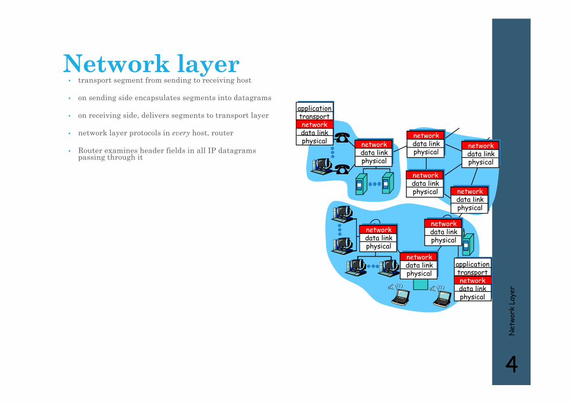
Network layer• transport segment from sending to receiving host
• on sending side encapsulates segments into datagrams
• on receiving side, delivers segments to transport layer
• network layer protocols in every host, router
• Router examines header fields in all IP datagrams passing through it
Net
work
Lay
er
4
networkdata linkphysical
networkdata linkphysical
networkdata linkphysical
networkdata linkphysical
networkdata linkphysical
networkdata linkphysical
networkdata linkphysical
networkdata linkphysical
applicationtransportnetworkdata linkphysical
applicationtransportnetworkdata linkphysical
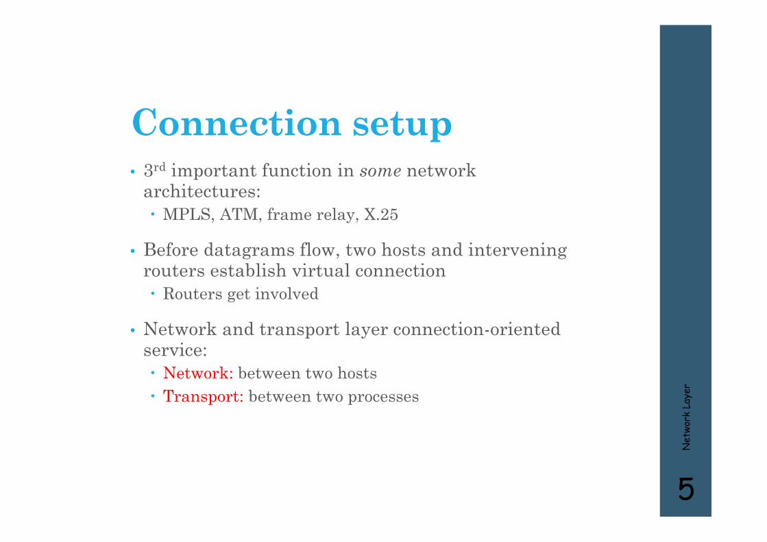
Connection setup• 3rd important function in some network
architectures: MPLS, ATM, frame relay, X.25
• Before datagrams flow, two hosts and intervening routers establish virtual connection Routers get involved
• Network and transport layer connection-oriented service: Network: between two hosts Transport: between two processes
Net
work
Lay
er
5

Network service model
Example services for individual datagrams:
• guaranteed delivery
• Guaranteed delivery with less than 40 msec delay
Example services for a flow of datagrams:
• In-order datagram delivery
• Guaranteed minimum bandwidth to flow
• Restrictions on changes in inter-packet spacing
Net
work
Lay
er
6
Q: What service model for “channel” transporting datagrams from sender to receiver?
Network layer connection and connection-less service• Datagram network provides network-layer
connectionless service
• VC network provides network-layer connection service
• Analogous to the transport-layer services, but: Service: host-to-host No choice: network provides one or the other Implementation: in the core
Net
work
Lay
er
7

Virtual circuits
• call setup, teardown for each call before data can flow
• each packet carries VC identifier (not destination host address)
• every router on source-dest path maintains “state” for each passing connection
• link, router resources (bandwidth, buffers) may be allocated to VC
“source-to-dest path behaves much like telephone circuit” performance-wise network actions along source-to-dest path
Net
work
Lay
er
8
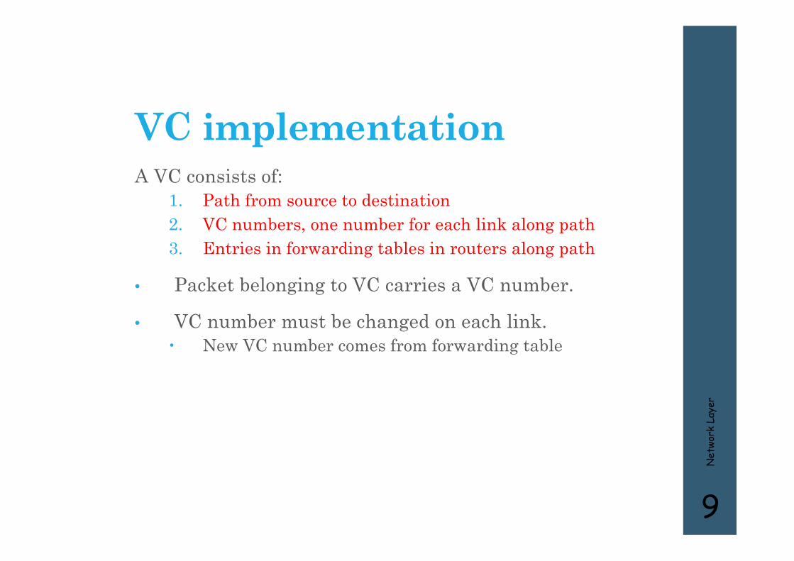
VC implementationA VC consists of:
1. Path from source to destination2. VC numbers, one number for each link along path3. Entries in forwarding tables in routers along path
• Packet belonging to VC carries a VC number.
• VC number must be changed on each link. New VC number comes from forwarding table
Net
work
Lay
er
9

Forwarding table
Net
work
Lay
er
10
12 22 32
1 23
VC number
interfacenumber
Incoming interface Incoming VC # Outgoing interface Outgoing VC #
1 12 3 222 63 1 18 3 7 2 171 97 3 87… … … …
Forwarding table innorthwest router:
Routers maintain connection state information!
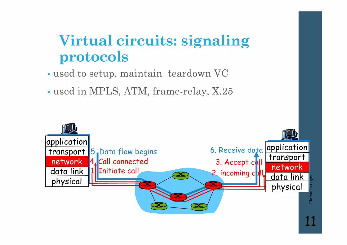
Virtual circuits: signaling protocols
• used to setup, maintain teardown VC
• used in MPLS, ATM, frame-relay, X.25
Net
work
Lay
er
11
applicationtransportnetworkdata linkphysical
applicationtransportnetworkdata linkphysical
1. Initiate call 2. incoming call3. Accept call4. Call connected
5. Data flow begins 6. Receive data

Datagram networks• no call setup at network layer• routers: no state about end-to-end connections no network-level concept of “connection”
• packets forwarded using destination host address packets between same source-dest pair may take different
paths
Net
work
Lay
er
12
applicationtransportnetworkdata linkphysical
applicationtransportnetworkdata linkphysical
1. Send data 2. Receive data
Net
work
Lay
er
13
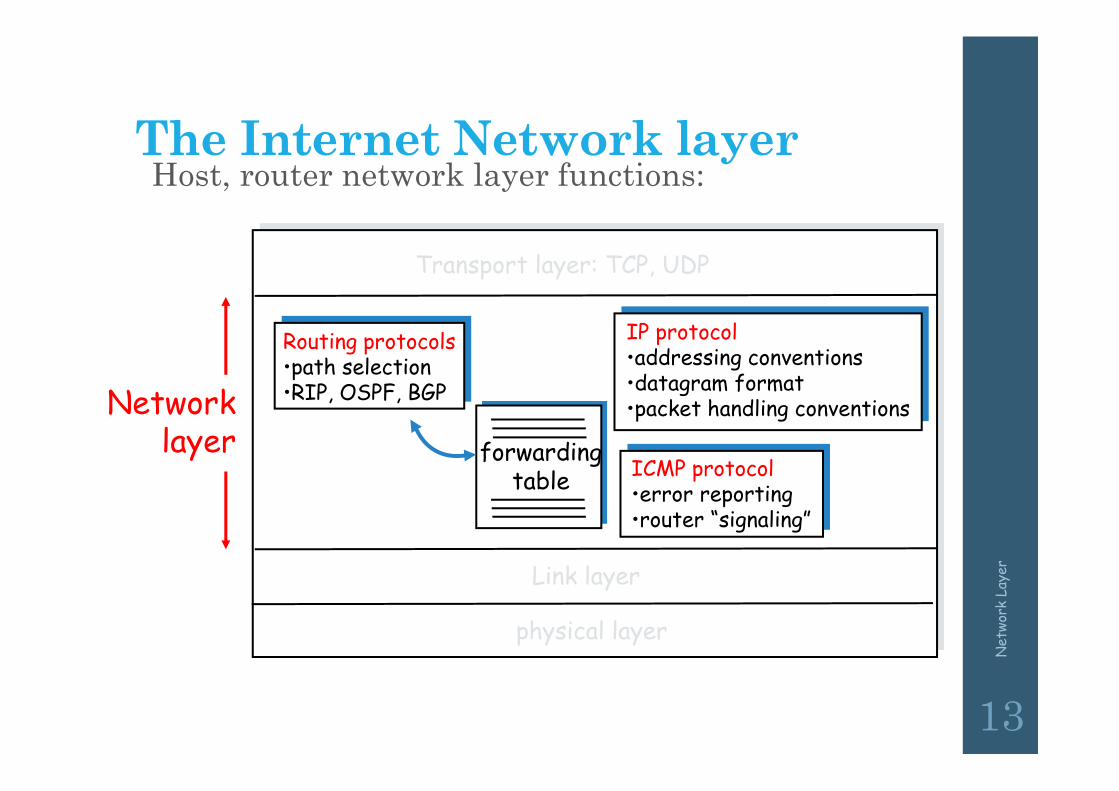
The Internet Network layer
forwardingtable
Host, router network layer functions:
Routing protocols•path selection•RIP, OSPF, BGP
IP protocol•addressing conventions•datagram format•packet handling conventions
ICMP protocol•error reporting•router “signaling”
Transport layer: TCP, UDP
Link layer
physical layer
Networklayer
Net
work
Lay
er
14
Service Model• Connectionless (datagram-based)• Best-effort delivery (unreliable service) packets are lost packets are delivered out of order duplicate copies of a packet are delivered packets can be delayed for a long time

Comparison of Virtual-Circuit and Datagram Subnets
Net
work
Lay
er
15
5-4
Inter - Networking• Hubs
• Bridges
• Switches
• Routers
Net
work
Lay
er
16
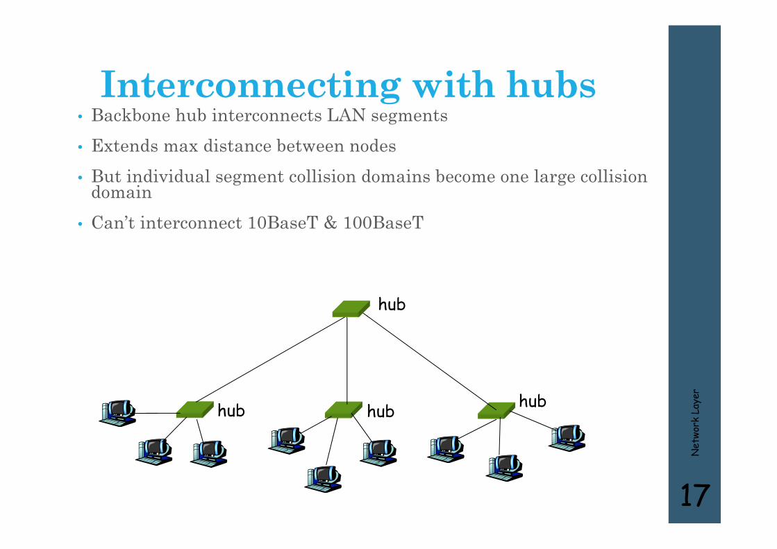
Interconnecting with hubs• Backbone hub interconnects LAN segments• Extends max distance between nodes• But individual segment collision domains become one large collision
domain• Can’t interconnect 10BaseT & 100BaseT
Net
work
Lay
er
17
hub hub hub
hub
Bridges and LAN Switches
• Bridges and LAN Switches Class of switches that is used to forward packets between
shared-media LANs such as Ethernets Known as LAN switches Referred to as Bridges
Suppose you have a pair of Ethernets that you want to interconnect One approach is put a repeater in between them
It might exceed the physical limitation of the Ethernet No more than four repeaters between any pair of hosts No more than a total of 2500 m in length is allowed
An alternative would be to put a node between the two Ethernets and have the node forward frames from one Ethernet to the other This node is called a Bridge A collection of LANs connected by one or more bridges is usually
said to form an Extended LAN
Bridges and LAN Switches
• Simplest Strategy for Bridges Accept LAN frames on their inputs and forward them
out to all other outputs Used by early bridges
• Learning Bridges Observe that there is no need to forward all the
frames that a bridge receives
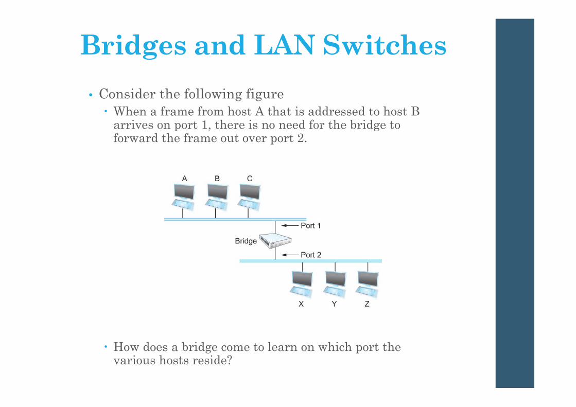
• Consider the following figure When a frame from host A that is addressed to host B
arrives on port 1, there is no need for the bridge to forward the frame out over port 2.
How does a bridge come to learn on which port the various hosts reside?
Bridges and LAN Switches

Bridges and LAN Switches
• Solution Download a table into the bridge
Who does the download? Human
Too much work for maintenance
A
Bridge
B C
X Y Z
Port 1
Port 2
Host Port
--------------------
A 1
B 1
C 1
X 2
Y 2
Z 2

Bridges and LAN Switches• Can the bridge learn this information by itself? Yes
• How Each bridge inspects the source address in all the frames
it receives Record the information at the bridge and build the table When a bridge first boots, this table is empty Entries are added over time A timeout is associated with each entry The bridge discards the entry after a specified period of
time To protect against the situation in which a host is moved from
one network to another
• If the bridge receives a frame that is addressed to host not currently in the table Forward the frame out on all other ports

Bridges and LAN Switches• Strategy works fine if the extended LAN does not
have a loop in it
• Why? Frames potentially loop through the extended LAN
forever
Bridges B1, B4, and B6 form a loop

Bridges and LAN Switches• How does an extended LAN come to have a loop in
it? Network is managed by more than one administrator For example, it spans multiple departments in an
organization It is possible that no single person knows the entire
configuration of the network A bridge that closes a loop might be added without anyone
knowing
Loops are built into the network to provide redundancy in case of failures
• Solution Distributed Spanning Tree Algorithm
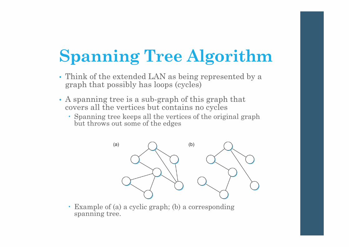
Spanning Tree Algorithm• Think of the extended LAN as being represented by a
graph that possibly has loops (cycles)
• A spanning tree is a sub-graph of this graph that covers all the vertices but contains no cycles Spanning tree keeps all the vertices of the original graph
but throws out some of the edges
Example of (a) a cyclic graph; (b) a corresponding spanning tree.

Spanning Tree Algorithm• Developed by Radia Perlman at Digital A protocol used by a set of bridges to agree upon a
spanning tree for a particular extended LAN IEEE 802.1 specification for LAN bridges is based on
this algorithm
Each bridge decides the ports over which it is and is not willing to forward frames In a sense, it is by removing ports from the topology that
the extended LAN is reduced to an acyclic tree It is even possible that an entire bridge will not
participate in forwarding frames

Spanning Tree Algorithm• Algorithm is dynamic The bridges are always prepared to reconfigure
themselves into a new spanning tree if some bridges fail
• Main idea Each bridge selects the ports over which they will
forward the frames

Spanning Tree Algorithm• Algorithm selects ports as follows: Each bridge has a unique identifier B1, B2, B3,…and so on.
Elect the bridge with the smallest id as the root of the spanning tree
The root bridge always forwards frames out over all of its ports
Each bridge computes the shortest path to the root and notes which of its ports is on this path This port is selected as the bridge’s preferred path to the
root Finally, all the bridges connected to a given LAN elect
a single designated bridge that will be responsible for forwarding frames toward the root bridge
Spanning Tree Algorithm• Each LAN’s designated bridge is the one that is
closest to the root
• If two or more bridges are equally close to the root, Then select bridge with the smallest id
• Each bridge is connected to more than one LAN So it participates in the election of a designated bridge
for each LAN it is connected to. Each bridge decides if it is the designated bridge
relative to each of its ports The bridge forwards frames over those ports for which
it is the designated bridge

Spanning Tree Algorithm• B1 is the root bridge
• B3 and B5 are connected to LAN A, but B5 is the designated bridge
• B5 and B7 are connected to LAN B, but B5 is the designated bridge
Spanning Tree Algorithm• Initially each bridge thinks it is the root, so it sends a
configuration message on each of its ports identifying itself as the root and giving a distance to the root of 0
• Upon receiving a configuration message over a particular port, the bridge checks to see if the new message is better than the current best configuration message recorded for that port
• The new configuration is better than the currently recorded information if It identifies a root with a smaller id or It identifies a root with an equal id but with a shorter
distance or The root id and distance are equal, but the sending bridge
has a smaller id

Spanning Tree Algorithm• If the new message is better than the currently
recorded one, The bridge discards the old information and saves the
new information It first adds 1 to the distance-to-root field
• When a bridge receives a configuration message indicating that it is not the root bridge (that is, a message from a bridge with smaller id) The bridge stops generating configuration messages
on its own Only forwards configuration messages from other
bridges after 1 adding to the distance field

Spanning Tree Algorithm
• When a bridge receives a configuration message that indicates it is not the designated bridge for that port => a message from a bridge that is closer to the root or
equally far from the root but with a smaller id The bridge stops sending configuration messages over that
port
• When the system stabilizes, Only the root bridge is still generating configuration
messages. Other bridges are forwarding these messages only
over ports for which they are the designated bridge

Spanning Tree Algorithm• Consider the situation when the power had just
been restored to the building housing the following network
• All bridges would start off by claiming to be the root

Spanning Tree Algorithm• Denote a configuration message from node X in which
it claims to be distance d from the root node Y as (Y, d, X)
• Consider the activity at node B3

Spanning Tree Algorithm• B3 receives (B2, 0, B2)
• Since 2 < 3, B3 accepts B2 as root
• B3 adds 1 to the distance advertised by B2 and sends (B2, 1, B3) to B5
• Meanwhile B2 accepts B1 as root because it has the lower id and it sends (B1, 1, B2) toward B3
• B5 accepts B1 as root and sends (B1, 1, B5) to B3
• B3 accepts B1 as root and it notes that both B2 and B5 are closer to the root than it is. Thus B3 stops forwarding messages on
both its interfaces This leaves B3 with both ports not
selected
Spanning Tree Algorithm• Even after the system has stabilized, the root bridge
continues to send configuration messages periodically Other bridges continue to forward these messages
• When a bridge fails, the downstream bridges will not receive the configuration messages
• After waiting a specified period of time, they will once again claim to be the root and the algorithm starts again
• Note Although the algorithm is able to reconfigure the
spanning tree whenever a bridge fails, it is not able to forward frames over alternative paths for the sake of routing around a congested bridge
Spanning Tree Algorithm• Limitation of Bridges Do not scale Spanning tree algorithm does not scale Broadcast does not scale
Do not accommodate heterogeneity
Switch• Link layer device stores and forwards Ethernet frames examines frame header and selectively forwards frame based on
MAC dest address when frame is to be forwarded on segment, uses CSMA/CD to
access segment
• transparent hosts are unaware of presence of switches
• plug-and-play, self-learning switches do not need to be configured
Net
work
Lay
er
39
Self learning• A switch has a switch table
• entry in switch table: (MAC Address, Interface, Time Stamp) stale entries in table dropped (TTL can be 60 min)
• switch learns which hosts can be reached through which interfaces when frame received, switch “learns” location of sender: incoming LAN
segment records sender/location pair in switch table
Net
work
Lay
er
40
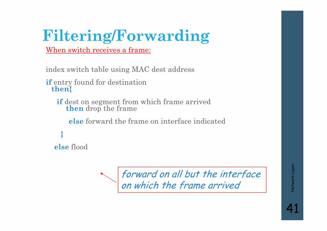
Filtering/ForwardingWhen switch receives a frame:
index switch table using MAC dest addressif entry found for destination
then{if dest on segment from which frame arrived
then drop the frameelse forward the frame on interface indicated
}else flood
Net
work
Lay
er
41
forward on all but the interface on which the frame arrived
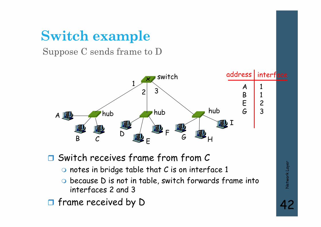
Switch exampleSuppose C sends frame to D
Net
work
Lay
er
42
Switch receives frame from from C notes in bridge table that C is on interface 1 because D is not in table, switch forwards frame into
interfaces 2 and 3 frame received by D
hub hub hub
switch
A
B CD
EF G H
I
address interfaceABEG
1123
12 3
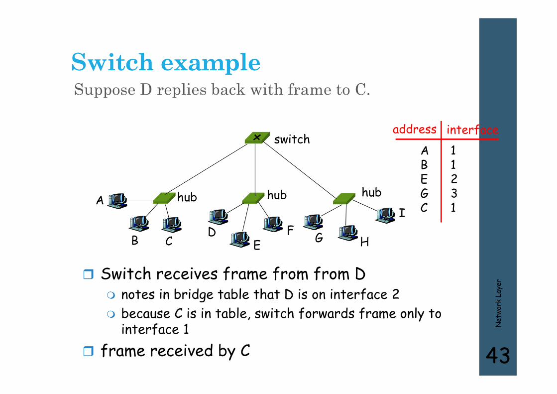
Switch exampleSuppose D replies back with frame to C.
Net
work
Lay
er
43
Switch receives frame from from D notes in bridge table that D is on interface 2 because C is in table, switch forwards frame only to
interface 1 frame received by C
hub hub hub
switch
A
B CD
EF G H
I
address interfaceABEGC
11231
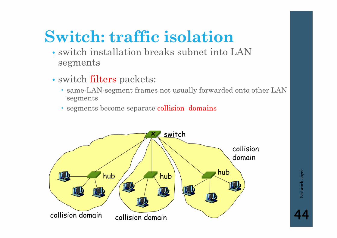
Switch: traffic isolation• switch installation breaks subnet into LAN
segments• switch filters packets: same-LAN-segment frames not usually forwarded onto other LAN
segments segments become separate collision domains
Net
work
Lay
er
44
hub hub hub
switch
collision domain collision domain
collision domain

Switches: dedicated access• Switch with many interfaces
• Hosts have direct connection to switch
• No collisions; full duplex
Switching: A-to-A’ and B-to-B’ simultaneously, no collisions
Net
work
Lay
er
45
switch
A
A’
B
B’
C
C’
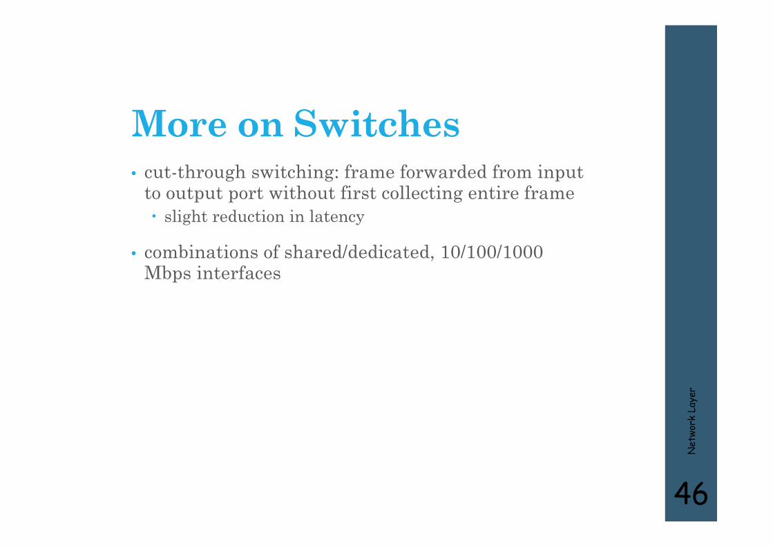
More on Switches• cut-through switching: frame forwarded from input
to output port without first collecting entire frame slight reduction in latency
• combinations of shared/dedicated, 10/100/1000 Mbps interfaces
Net
work
Lay
er
46

Institutional network
Net
work
Lay
er
47
hub hubhub
switch
to externalnetwork
router
IP subnet
mail server
web server
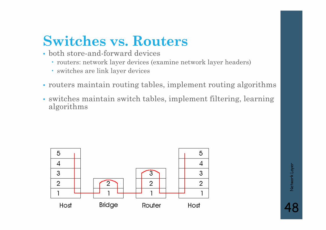
Switches vs. Routers• both store-and-forward devices routers: network layer devices (examine network layer headers) switches are link layer devices
• routers maintain routing tables, implement routing algorithms
• switches maintain switch tables, implement filtering, learning algorithms
Net
work
Lay
er
48
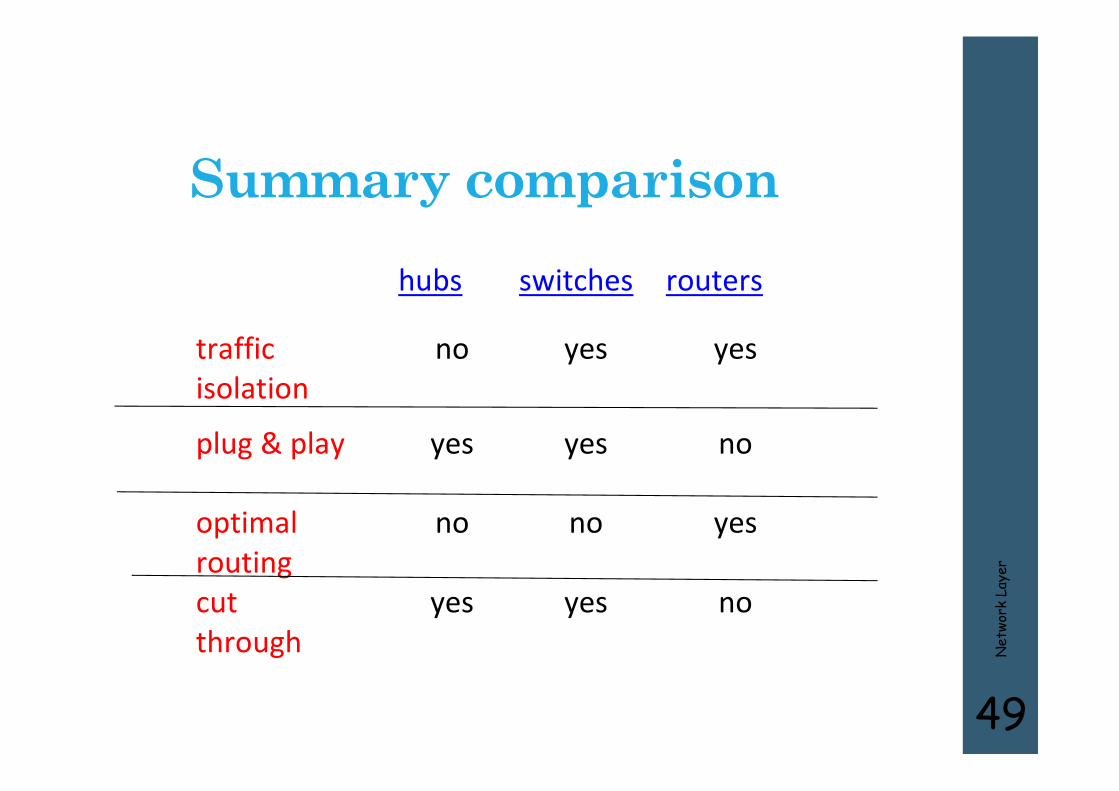
Summary comparison hubs switches routers
traffic isolation
no yes yes
plug & play yes yes no
optimal routing
no no yes
cut through
yes yes no
Net
work
Lay
er
49
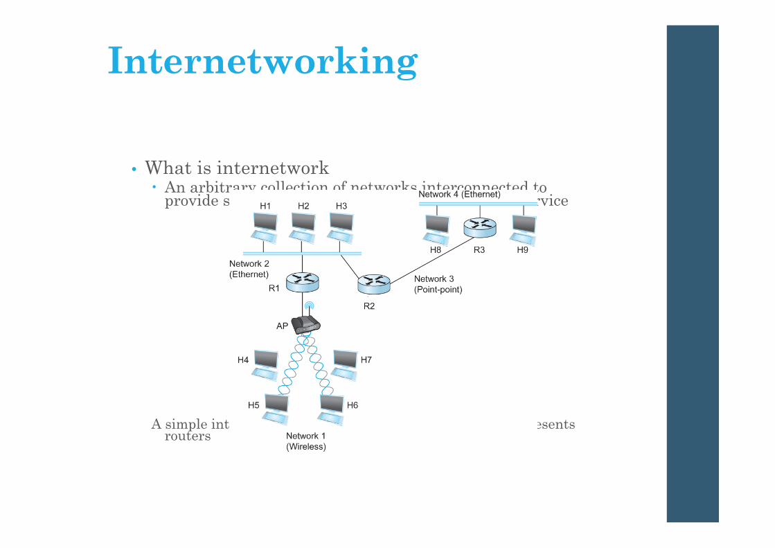
Internetworking
• What is internetwork An arbitrary collection of networks interconnected to
provide some sort of host-host to packet delivery service
A simple internetwork where H represents hosts and R represents routers
Internetworking
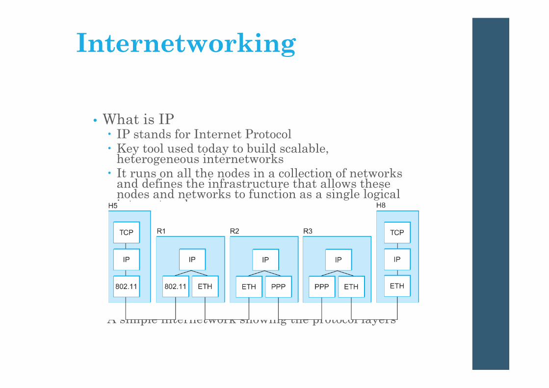
• What is IP IP stands for Internet Protocol Key tool used today to build scalable,
heterogeneous internetworks It runs on all the nodes in a collection of networks
and defines the infrastructure that allows these nodes and networks to function as a single logical internetwork
A simple internetwork showing the protocol layers
IP Service Model
• Packet Delivery Model Connectionless model for data delivery Best-effort delivery (unreliable service) packets are lost packets are delivered out of order duplicate copies of a packet are delivered packets can be delayed for a long time
• Global Addressing Scheme Provides a way to identify all hosts in
the network
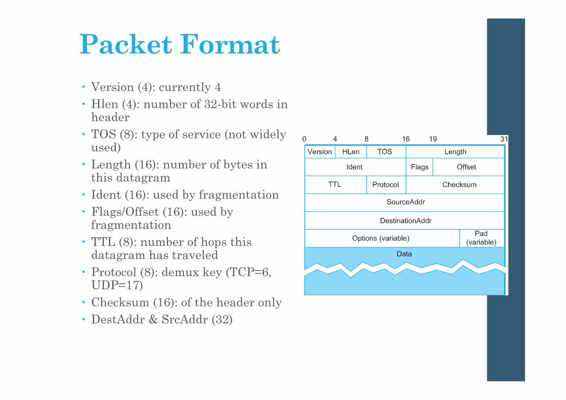
Packet Format Version (4): currently 4 Hlen (4): number of 32-bit words in
header TOS (8): type of service (not widely
used) Length (16): number of bytes in
this datagram Ident (16): used by fragmentation Flags/Offset (16): used by
fragmentation TTL (8): number of hops this
datagram has traveled Protocol (8): demux key (TCP=6,
UDP=17) Checksum (16): of the header only DestAddr & SrcAddr (32)

Net
work
Lay
er
54
IP Addressing: introduction• IP address: 32-bit
identifier for host, router interface
• interface: connection between host/router and physical link router’s typically have
multiple interfaces host may have multiple
interfaces IP addresses associated
with each interface
223.1.1.1
223.1.1.2
223.1.1.3
223.1.1.4 223.1.2.9
223.1.2.2
223.1.2.1
223.1.3.2223.1.3.1
223.1.3.27
223.1.1.1 = 11011111 00000001 00000001 00000001
223 1 11

IP AddressesIP address formats.
Net
work
Lay
er
55

IP Addresses (2)Special IP addresses.
Net
work
Lay
er
56
Net
work
Lay
er
57
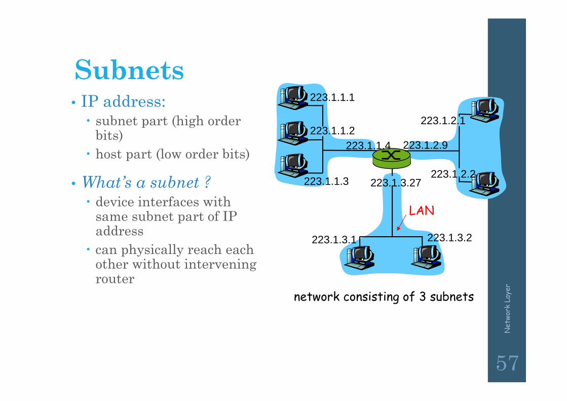
Subnets• IP address: subnet part (high order
bits) host part (low order bits)
• What’s a subnet ? device interfaces with
same subnet part of IP address
can physically reach each other without intervening router
223.1.1.1
223.1.1.2
223.1.1.3
223.1.1.4 223.1.2.9
223.1.2.2
223.1.2.1
223.1.3.2223.1.3.1
223.1.3.27
network consisting of 3 subnets
LAN
Net
work
Lay
er
58
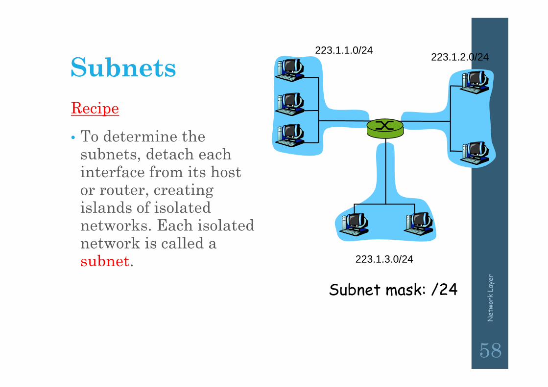
Subnets223.1.1.0/24 223.1.2.0/24
223.1.3.0/24
Recipe
• To determine the subnets, detach each interface from its host or router, creating islands of isolated networks. Each isolated network is called a subnet.
Subnet mask: /24

Net
work
Lay
er
59
SubnetsHow many? 223.1.1.1
223.1.1.3
223.1.1.4
223.1.2.2223.1.2.1
223.1.2.6
223.1.3.2223.1.3.1
223.1.3.27
223.1.1.2
223.1.7.0
223.1.7.1223.1.8.0223.1.8.1
223.1.9.1
223.1.9.2

Subnets
A class B network subnetted into 64 subnets.
Net
work
Lay
er
60
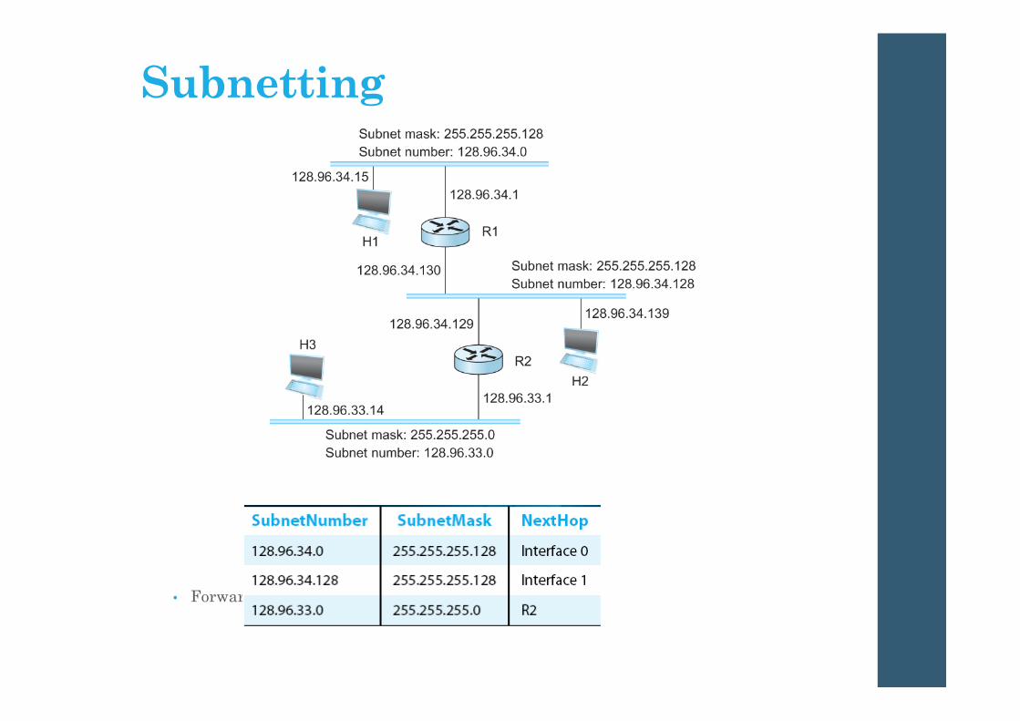
Subnetting
• Forwarding Table at Router R1
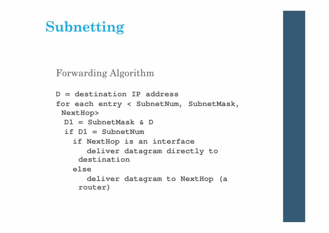
Subnetting
Forwarding Algorithm
D = destination IP addressfor each entry < SubnetNum, SubnetMask, NextHop>D1 = SubnetMask & Dif D1 = SubnetNumif NextHop is an interface
deliver datagram directly to destination
elsedeliver datagram to NextHop (a
router)

Net
work
Lay
er
63
IP addressing: CIDRCIDR: Classless InterDomain Routing subnet portion of address of arbitrary length address format: a.b.c.d/x, where x is # bits in subnet portion of address
11001000 00010111 00010000 00000000
subnetpart
hostpart
200.23.16.0/23
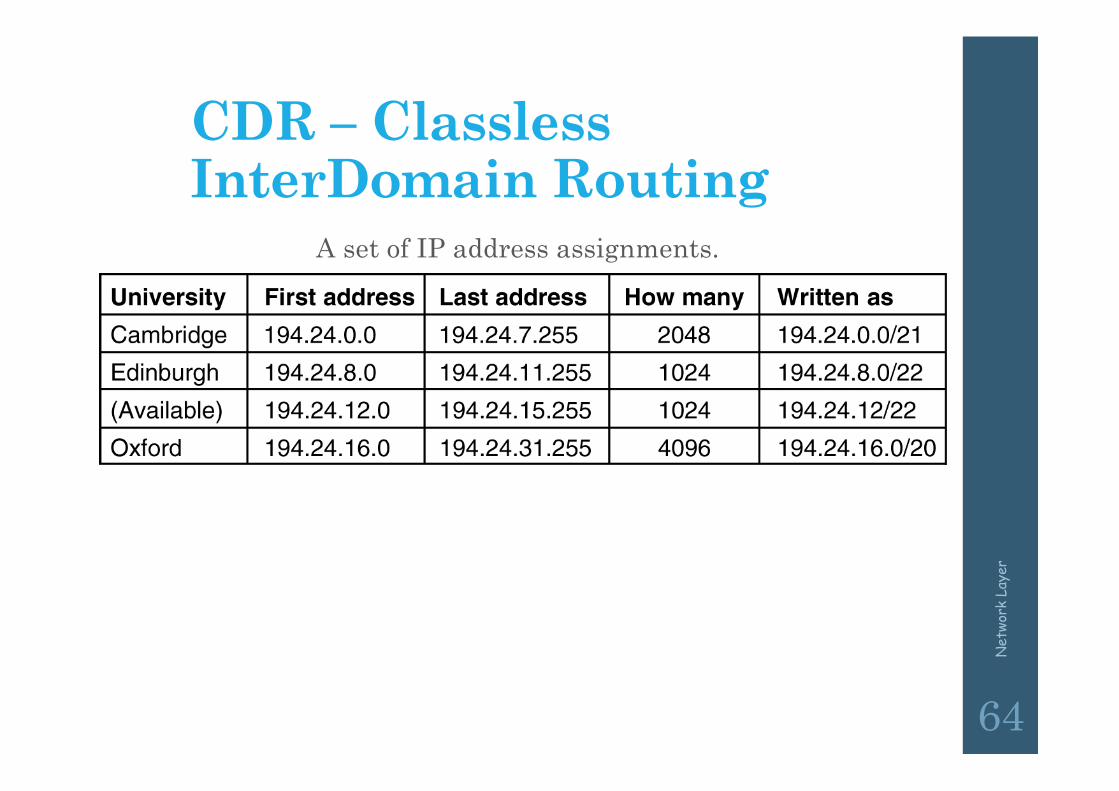
CDR – Classless InterDomain Routing
A set of IP address assignments.
5-59
Net
work
Lay
er
64

Net
work
Lay
er
65
IP addresses: how to get one?Q: How does network get subnet part of IP addr?
A: gets allocated portion of its provider ISP’s address space
ISP's block 11001000 00010111 00010000 00000000 200.23.16.0/20
Organization 0 11001000 00010111 00010000 00000000 200.23.16.0/23 Organization 1 11001000 00010111 00010010 00000000 200.23.18.0/23 Organization 2 11001000 00010111 00010100 00000000 200.23.20.0/23
... ….. …. ….Organization 7 11001000 00010111 00011110 00000000 200.23.30.0/23
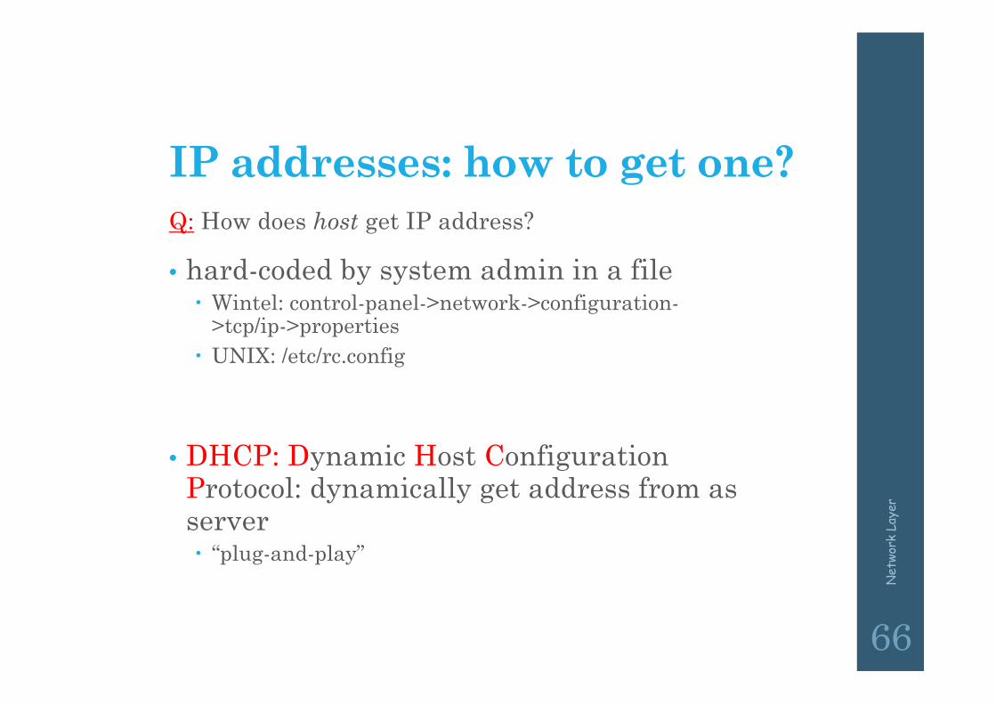
IP addresses: how to get one?Q: How does host get IP address?
• hard-coded by system admin in a file Wintel: control-panel->network->configuration-
>tcp/ip->properties UNIX: /etc/rc.config
• DHCP: Dynamic Host Configuration Protocol: dynamically get address from as server “plug-and-play”
Net
work
Lay
er
66
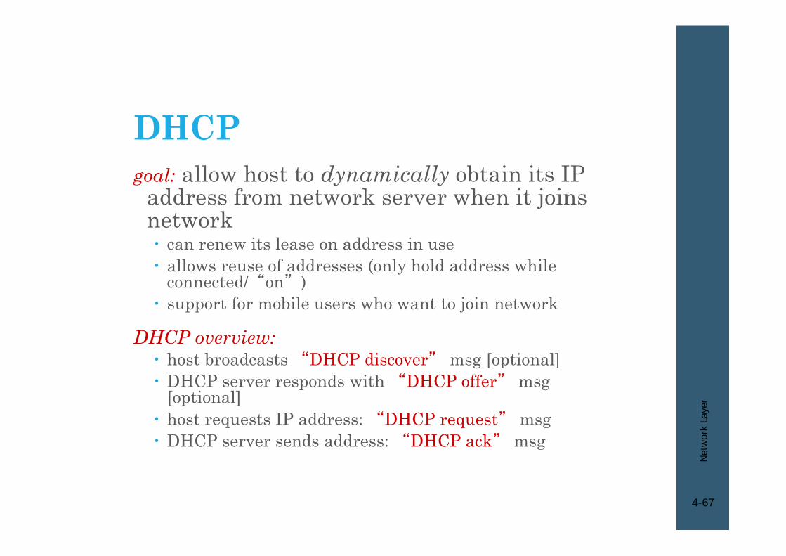
DHCPgoal: allow host to dynamically obtain its IP
address from network server when it joins network can renew its lease on address in use allows reuse of addresses (only hold address while
connected/“on”) support for mobile users who want to join network
DHCP overview: host broadcasts “DHCP discover” msg [optional] DHCP server responds with “DHCP offer” msg
[optional] host requests IP address: “DHCP request” msg DHCP server sends address: “DHCP ack” msg
Net
wor
k La
yer
4-67

DHCP• There is at least one DHCP server for an administrative
domain
• DHCP server maintains a pool of available addresses
• Newly booted or attached host sends DHCPDISCOVER message to a special IP address (255.255.255.255)
• DHCP relay agent unicasts the message to DHCP server and waits for the response
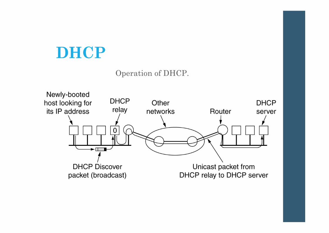
DHCPOperation of DHCP.

DHCP client-server scenario
Net
wor
k La
yer
4-70
223.1.1.0/24
223.1.2.0/24
223.1.3.0/24
223.1.1.1
223.1.1.3
223.1.1.4 223.1.2.9
223.1.3.2223.1.3.1
223.1.1.2
223.1.3.27223.1.2.2
223.1.2.1
DHCPserver
arriving DHCPclient needs address in thisnetwork
Net
wor
k La
yer
4-71
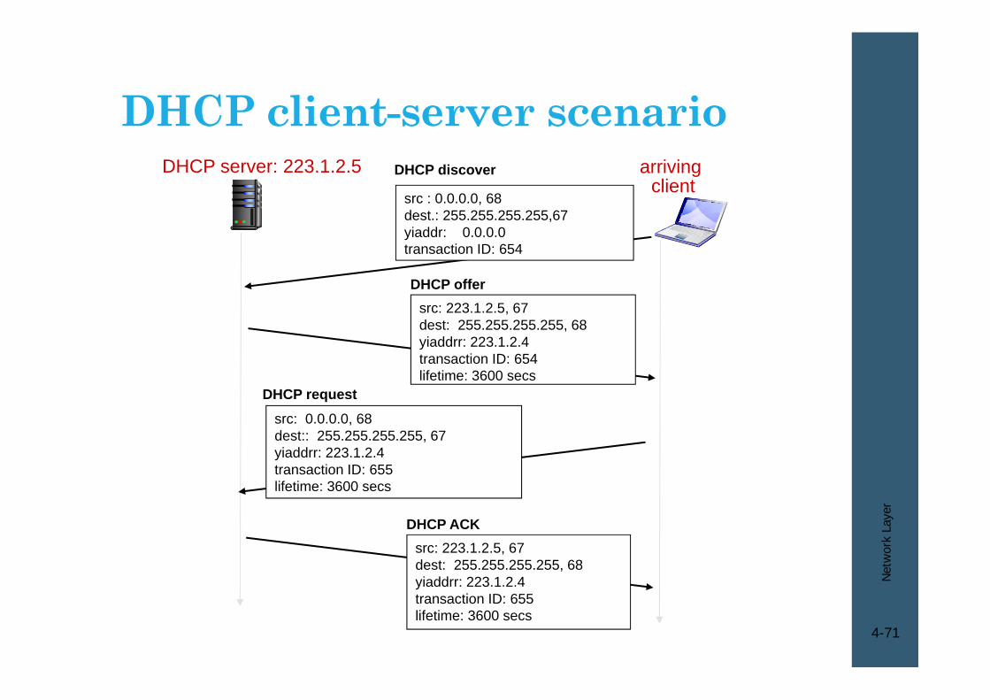
DHCP server: 223.1.2.5 arrivingclient
DHCP discover
src : 0.0.0.0, 68 dest.: 255.255.255.255,67yiaddr: 0.0.0.0transaction ID: 654
DHCP offersrc: 223.1.2.5, 67 dest: 255.255.255.255, 68yiaddrr: 223.1.2.4transaction ID: 654lifetime: 3600 secs
DHCP requestsrc: 0.0.0.0, 68 dest:: 255.255.255.255, 67yiaddrr: 223.1.2.4transaction ID: 655lifetime: 3600 secs
DHCP ACKsrc: 223.1.2.5, 67 dest: 255.255.255.255, 68yiaddrr: 223.1.2.4transaction ID: 655lifetime: 3600 secs
DHCP client-server scenario
Net
wor
k La
yer
4-72
DHCP: more than IP addressesDHCP can return more than just allocated IP
address on subnet: address of first-hop router for client name and IP address of DNS sever network mask (indicating network versus host portion
of address)
Net
wor
k La
yer
4-73
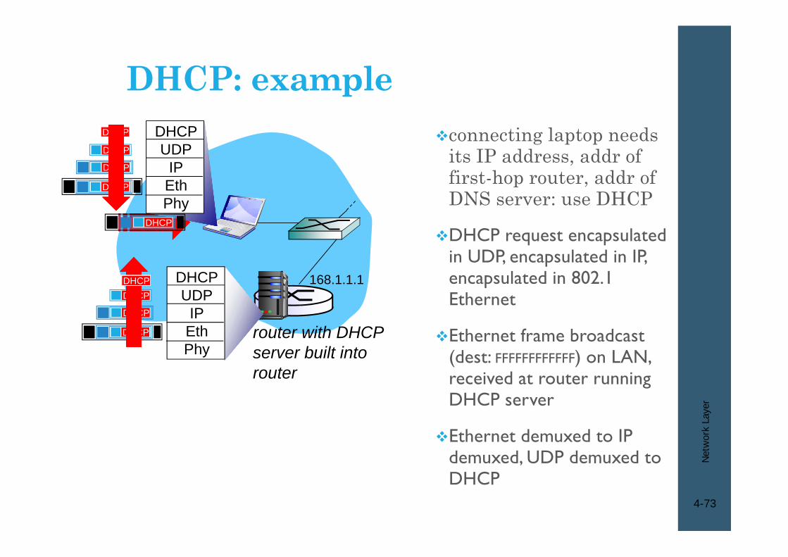
connecting laptop needs its IP address, addr of first-hop router, addr of DNS server: use DHCP
DHCP request encapsulated in UDP, encapsulated in IP, encapsulated in 802.1 Ethernet
Ethernet frame broadcast (dest: FFFFFFFFFFFF) on LAN, received at router running DHCP server
Ethernet demuxed to IP demuxed, UDP demuxed to DHCP
router with DHCP server built into router
168.1.1.1
DHCPUDP
IPEthPhy
DHCP
DHCP
DHCP
DHCP
DHCP
DHCPUDP
IPEthPhy
DHCP
DHCP
DHCP
DHCPDHCP
DHCP: example
Net
wor
k La
yer
4-74
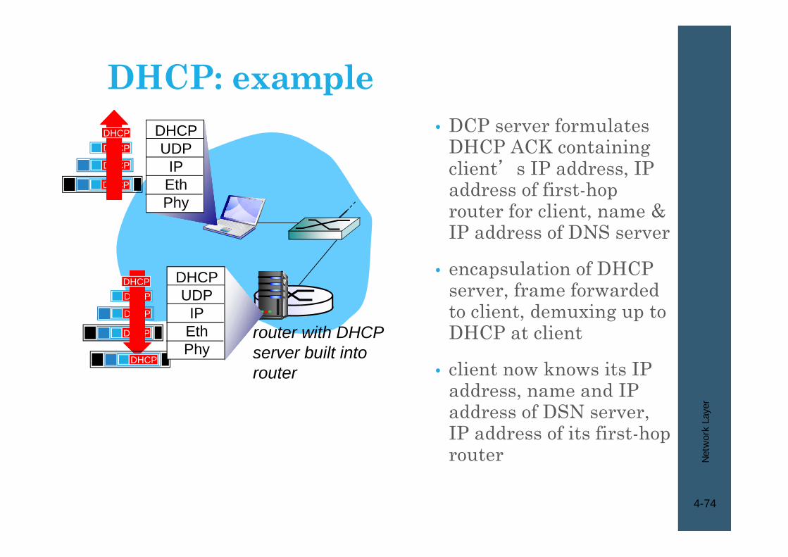
• DCP server formulates DHCP ACK containing client’s IP address, IP address of first-hop router for client, name & IP address of DNS server
• encapsulation of DHCP server, frame forwarded to client, demuxing up to DHCP at client
• client now knows its IP address, name and IP address of DSN server, IP address of its first-hop router
DHCP: example
router with DHCP server built into router
DHCP
DHCP
DHCP
DHCP
DHCPUDP
IPEthPhy
DHCP
DHCPUDP
IPEthPhy
DHCP
DHCP
DHCP
DHCP
Net
wor
k La
yer
4-75
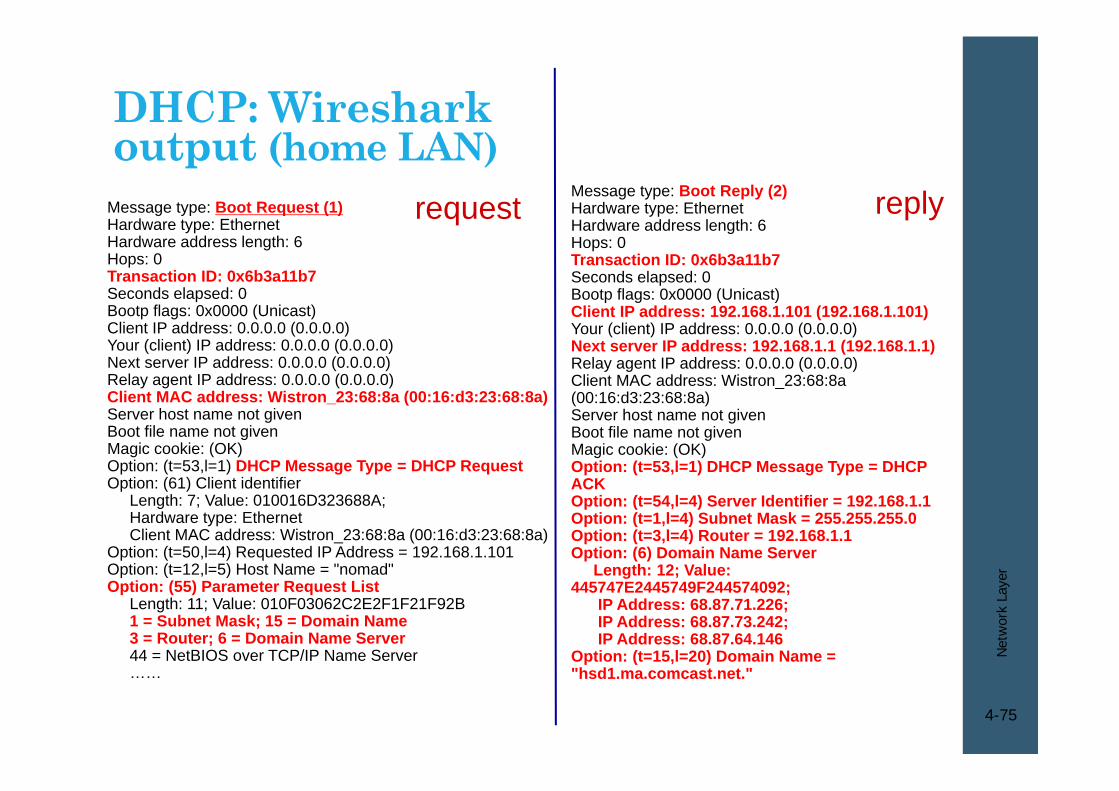
DHCP: Wireshark output (home LAN)
Message type: Boot Reply (2)Hardware type: EthernetHardware address length: 6Hops: 0Transaction ID: 0x6b3a11b7Seconds elapsed: 0Bootp flags: 0x0000 (Unicast)Client IP address: 192.168.1.101 (192.168.1.101)Your (client) IP address: 0.0.0.0 (0.0.0.0)Next server IP address: 192.168.1.1 (192.168.1.1)Relay agent IP address: 0.0.0.0 (0.0.0.0)Client MAC address: Wistron_23:68:8a (00:16:d3:23:68:8a)Server host name not givenBoot file name not givenMagic cookie: (OK)Option: (t=53,l=1) DHCP Message Type = DHCP ACKOption: (t=54,l=4) Server Identifier = 192.168.1.1Option: (t=1,l=4) Subnet Mask = 255.255.255.0Option: (t=3,l=4) Router = 192.168.1.1Option: (6) Domain Name Server
Length: 12; Value: 445747E2445749F244574092;
IP Address: 68.87.71.226;IP Address: 68.87.73.242; IP Address: 68.87.64.146
Option: (t=15,l=20) Domain Name = "hsd1.ma.comcast.net."
replyMessage type: Boot Request (1)Hardware type: EthernetHardware address length: 6Hops: 0Transaction ID: 0x6b3a11b7Seconds elapsed: 0Bootp flags: 0x0000 (Unicast)Client IP address: 0.0.0.0 (0.0.0.0)Your (client) IP address: 0.0.0.0 (0.0.0.0)Next server IP address: 0.0.0.0 (0.0.0.0)Relay agent IP address: 0.0.0.0 (0.0.0.0)Client MAC address: Wistron_23:68:8a (00:16:d3:23:68:8a)Server host name not givenBoot file name not givenMagic cookie: (OK)Option: (t=53,l=1) DHCP Message Type = DHCP RequestOption: (61) Client identifier
Length: 7; Value: 010016D323688A; Hardware type: EthernetClient MAC address: Wistron_23:68:8a (00:16:d3:23:68:8a)
Option: (t=50,l=4) Requested IP Address = 192.168.1.101Option: (t=12,l=5) Host Name = "nomad"Option: (55) Parameter Request List
Length: 11; Value: 010F03062C2E2F1F21F92B1 = Subnet Mask; 15 = Domain Name3 = Router; 6 = Domain Name Server44 = NetBIOS over TCP/IP Name Server……
request

Net
work
Lay
er
76
IP addressing: the last word...Q: How does an ISP get block of addresses?
A: ICANN: Internet Corporation for Assigned Names and Numbers allocates addresses manages DNS assigns domain names, resolves disputes
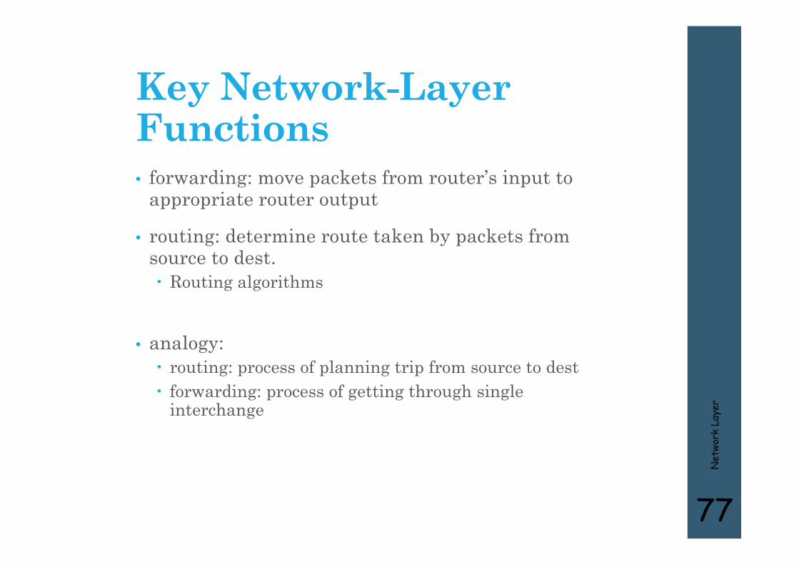
Key Network-Layer Functions• forwarding: move packets from router’s input to
appropriate router output
• routing: determine route taken by packets from source to dest. Routing algorithms
• analogy: routing: process of planning trip from source to dest forwarding: process of getting through single
interchange
Net
work
Lay
er
77

Interplay between routing and forwarding
Net
work
Lay
er
78
1
23
0111
value in arrivingpacket’s header
routing algorithm
local forwarding tableheader value output link
0100010101111001
3221

Forwarding table
Net
work
Lay
er
79
Destination Address Range Link Interface
11001000 00010111 00010000 00000000through 0
11001000 00010111 00010111 11111111
11001000 00010111 00011000 00000000through 1
11001000 00010111 00011000 11111111
11001000 00010111 00011001 00000000through 2
11001000 00010111 00011111 11111111
otherwise 3
4 billion possible entries
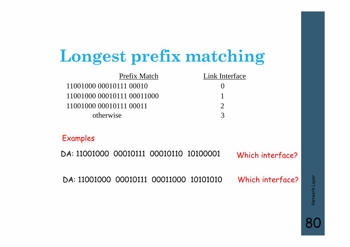
Longest prefix matching
Net
work
Lay
er
80
Prefix Match Link Interface11001000 00010111 00010 011001000 00010111 00011000 111001000 00010111 00011 2
otherwise 3
DA: 11001000 00010111 00011000 10101010
Examples
DA: 11001000 00010111 00010110 10100001 Which interface?
Which interface?


![Http://linc.ucy.ac.cy Andreas Papadopoulos - andpapad@cs.ucy.ac.cy [DEXA 2015] Clustering Attributed Multi-graphs with Information Ranking 26th International.](https://static.fdocuments.us/doc/165x107/56649f295503460f94c434ae/httplincucyaccy-andreas-papadopoulos-andpapadcsucyaccy-dexa-2015.jpg)