
EPL 0005704 Article
9
1. Introduction 1.1. Background Having regularly received enquiries regarding appro- priate gripping forces for composite test coupons, and regarding specimen failures not only at the jaw face, but within the tabbed and gripped section, the authors sought to clarify the origins of these problems. The results of this initial investigation were considered of significant concern to the composites testing com- munity, so are published within this paper while a wider investigation is ongoing. Instron (Dynamic Systems) noticed that a rise in commercial demand for composites fatigue data started in the mid 2000’s and this has continued to grow unabated since then. This was originally driven by the wind turbine industry, where structures expe- rience significant cyclic strain over a long life cycle. By comparison, academic research interest in com- posites fatigue was particularly strong during the 1980s through into the mid-90s, along with all aspects of mechanical characterization of composites. Although numbers of publications remained consis- tent ever since, the topic seemed to become a less popular research and conference topic until around 2010, since when there has been a rapid increase in activity, primarily driven by the aerospace and auto- motive industries. It has long been known and demonstrated that grip- ping methods can significantly affect both the value and the consistency of results in mechanical testing of composites [1, 2] and certain test practices have become commonly accepted for quasi-static tests. Nonetheless, it is interesting to note that ASTM D3039 for tensile testing of composites remarks that ‘Design of mechanical test coupons, especially those using end tabs, remains to a large extent an art rather 480 Specimen gripping effects in composites fatigue testing – Concerns from initial investigation P. B. S. Bailey 1* , A. D. Lafferty 2 1 Instron Materials Testing, Coronation Road, HP12 3SY High Wycombe, United Kingdom 2 Department of Materials Science and Engineering, University of Sheffield, Broad Lane, Sheffield, United Kingdom Received 14 August 2014; accepted in revised form 10 December 2014 Abstract. This paper presents the findings of an initial investigation into effects of end tabs and gripping force on speci- mens for fatigue testing of structural composites. Live measurement of specimen compliance comparing extensometer measurements with grip displacement showed the impact of gripping on the dynamic behavior of the specimen. Use of ther- mal imaging enabled assessment of how load is introduced and carried along the specimen. The effect of grip pressure and comparative merits of popular solutions are examined in the context of fatigue testing of composites. Although for static tests these potential issues have been investigated extensively throughout the history of composites research, interest has only recently fallen upon their effects on dynamic loading. Data collected show that the gripping pressure at the ends of the specimen can affect results more significantly than may be anticipated. These early results suggest that solutions which are well established for quasi-static testing may cause problems in cyclic tests. Keywords: polymer composites, fracture and fatigue, material testing, thermography, stress concentration eXPRESS Polymer Letters Vol.9, No.5 (2015) 480–488 Available online at www.expresspolymlett.com DOI: 10.3144/expresspolymlett.2015.45 * Corresponding author, e-mail: [email protected] © BME-PT
-
Upload
luis-miguel-perez-pertuz -
Category
Documents
-
view
3 -
download
2
description
article
Transcript of EPL 0005704 Article
1. Introduction1.1. BackgroundHaving regularly received enquiries regarding appro-priate gripping forces for composite test coupons, andregarding specimen failures not only at the jaw face,but within the tabbed and gripped section, the authorssought to clarify the origins of these problems. Theresults of this initial investigation were considered ofsignificant concern to the composites testing com-munity, so are published within this paper while awider investigation is ongoing.Instron (Dynamic Systems) noticed that a rise incommercial demand for composites fatigue datastarted in the mid 2000’s and this has continued togrow unabated since then. This was originally drivenby the wind turbine industry, where structures expe-rience significant cyclic strain over a long life cycle.By comparison, academic research interest in com-
posites fatigue was particularly strong during the1980s through into the mid-90s, along with allaspects of mechanical characterization of composites.Although numbers of publications remained consis-tent ever since, the topic seemed to become a lesspopular research and conference topic until around2010, since when there has been a rapid increase inactivity, primarily driven by the aerospace and auto-motive industries.It has long been known and demonstrated that grip-ping methods can significantly affect both the valueand the consistency of results in mechanical testingof composites [1, 2] and certain test practices havebecome commonly accepted for quasi-static tests.Nonetheless, it is interesting to note that ASTMD3039 for tensile testing of composites remarks that‘Design of mechanical test coupons, especially thoseusing end tabs, remains to a large extent an art rather
480
Specimen gripping effects in composites fatigue testing –Concerns from initial investigationP. B. S. Bailey1*, A. D. Lafferty2
1Instron Materials Testing, Coronation Road, HP12 3SY High Wycombe, United Kingdom2Department of Materials Science and Engineering, University of Sheffield, Broad Lane, Sheffield, United Kingdom
Received 14 August 2014; accepted in revised form 10 December 2014
Abstract. This paper presents the findings of an initial investigation into effects of end tabs and gripping force on speci-mens for fatigue testing of structural composites. Live measurement of specimen compliance comparing extensometermeasurements with grip displacement showed the impact of gripping on the dynamic behavior of the specimen. Use of ther-mal imaging enabled assessment of how load is introduced and carried along the specimen.The effect of grip pressure and comparative merits of popular solutions are examined in the context of fatigue testing ofcomposites. Although for static tests these potential issues have been investigated extensively throughout the history ofcomposites research, interest has only recently fallen upon their effects on dynamic loading. Data collected show that thegripping pressure at the ends of the specimen can affect results more significantly than may be anticipated. These earlyresults suggest that solutions which are well established for quasi-static testing may cause problems in cyclic tests.
Keywords: polymer composites, fracture and fatigue, material testing, thermography, stress concentration
eXPRESS Polymer Letters Vol.9, No.5 (2015) 480–488Available online at www.expresspolymlett.comDOI: 10.3144/expresspolymlett.2015.45
*Corresponding author, e-mail: [email protected]© BME-PT

than a science, with no industry consensus on howto approach the engineering of the gripping interface’[3]. With growing drive to understand the dynamicbehavior of composites [4, 5], an increasing numberof experimentalists are finding it necessary to revisittheir previous methodologies for specimen prepara-tion.
1.2. Specimen and gripping designsStraight sided tensile specimens with compositeend tabs are now the accepted basic standard fortensile testing of composites [3, 4]. Unfortunately,in a majority of scenarios, where specimens com-prise a large amount of on-axis reinforcement, thesetypically fail at, or only just beyond, the end of thetab [1, 4, 7]. Qualitatively, the analyst knows thatthis will be the region of highest constraint, andtherefore the highest stress concentration, thereforephysics dictates that the specimen must fail in thatregion, unless there is some other, more significantstress raiser or defect. This has been demonstratedquite elegantly, for a variety of configurations, usingfinite element analysis [8] with some straightfor-ward mechanical tests provided to confirm the pre-dictions. A number of workers examined taperedend-tabs [1, 9, 10] but it appears that results variedfrom no noticeable difference in failure, through tocomplete success in establishing failure away fromthe grips. Whatsoever the efficacy of this technique,tapered tabs are now suggested in international stan-dards [3, 6], but anecdotally, many laboratory oper-ators look on them unfavourably due to the evenmore laborious preparation required. Early recom-mendations [1, 11] proposed a variety of tabs includ-ing different configurations of fibre reinforced tabmaterial, but also compliant abrasive pads, and alu-minium sheet. Only glass fibre reinforced polymermatrix tabs have been carried forward to currentinternational standards, although some researchersstill use aluminium tabs and consider them easierand more reliable to prepare.Several researchers experimented with a gentlyradiused gauge section, with the goal of forcing fail-ure into a region of known and consistent stress state(away from the grips) as is well established for met-als and plastics testing. Some work is published inopen literature [12–14], but the authors have alsobeen privileged to be shown similar results by indus-trial partners who have undertaken similar whichremains unpublished. In certain respects, the pub-
lished work shows a basic level of success, in termsof generating failure within the designated gaugesection. However, this does not appear to signifi-cantly improve repeatability; it is unclear whether thedominant factor in variability is therefore related tothe material or to the specimen preparation. Moreimportantly, a non-critical failure is observed in manytests presented; prior to complete tensile rupture,the specimens develop a shear failure, parallel to thetensile axis, aligned with the edges of the narrowestpoint of the gauge section. This is particularly con-cerning for fatigue analyses, where considerableinsight may be obtained by calculating the dynamicbehavior of the specimen (for example stiffness, mod-ulus, loss tangent, cyclic work done); clearly if thegeometry of the load carrying section of the speci-men changes, then any such calculations will showa change in output, but will no longer give a compara-ble measure of the material performance. This mightbe circumvented by use of strain gauges bondeddirectly to the specimen, but this raises the risk of notmeasuring a sufficiently large surface area to be rep-resentative, especially with commercial demand foruse of large fibre tows and woven reinforcements.By comparison, the use of open-hole specimens forfatigue does appear to reliably force failure into adefined location, and although this was demon-strated some time ago [15, 16], it was not developedinto an international standard until 2011 [17] and is asyet only used by a small number of workers. Earlywork on fatigue damage in composites also exam-ined the possibility of using on-axis uni-direction-ally reinforced material with an elongate, transverse,open hole. Growth of the longitudinal fractures prop-agating from the edges of the hole (as seen from theedges of the radii on dumbbell specimens discussedabove) was evaluated, with some success, but theconcept does not appear to have been advancedbeyond the original work by Spearing and Beau-mont [18].
1.3. Clamping pressureHistorically, mechanical testing practitioners haveoften used a ‘rule of thumb’ that the gripping forceon the ends of a typical specimen should be approx-imately 10 to 15% larger than the maximum axial testload to be applied. Although at present the authorscannot identify the origins of this guideline, it seemshighly probable that it originates in testing of met-als coupons, where specimens have more compliant
Bailey and Lafferty – eXPRESS Polymer Letters Vol.9, No.5 (2015) 480–488
481

surfaces making them easier to indent and grip. Fur-thermore a majority of tensile testing on metals andpolymers utilizes wasted specimens where thegripped section is wider than the gauge length. It isthe authors’ opinion that this level of clamping pres-sure is usually inadequate for typical, parallel sidedspecimens, of structural composites.
2. Materials and experimental pocedure2.1. Specimen preparationTests were conducted on E-glass fibre reinforcedepoxy resin sheet, prepared by wet lay-up and vac-uum consolidation.Industrial grade, low temperature curing epoxy resinwas used, with fibre in the form of E-glass 280 gsmnon-crimp fabric. All specimens were produced inone batch, using the same batches of raw materials.The raw materials used in this initial work weregeneric industrial products, as supplied by East CoastFibre Supplies, who do not offer further certifica-tion of composition or mechanical performance.Material was produced by wet laying 6 plies of non-crimp fabric between polyamide peel-ply releasefilm, on a polished steel caul plate, then vacuum con-solidating at better than 0.95 bar until gelled. Theconsolidated material was moved to an oven (still oncaul plate within bag and under vacuum) for finalcure at 60°C for 4 hours.Specimens were prepared in accordance with ISO257 [6], cut by diamond wheel, with parallel gaugesection of 25 by 150 mm. The 50 mm long grippedsection was adjusted for comparison between: tabs ofcross-plied, glass fibre reinforced epoxy, 2 mm thick[6, 11]; tabs of aluminium sheet, 2 mm thick [11]; nobonded tab [1].Where used, the adhesive was the same compositionand subject to the same cure as the matrix material.Bonded surfaces were thoroughly solvent washedwith acetone, then abraded, then re-washed andallowed to dry, prior to bonding. Composite surfaceswere abraded using bonded abrasive paper; alu-minium tabs were grit blasted with clean silica sand.
2.2. Mechanical testingSpecimens were tested using an Instron 8801MTservohydraulic materials testing system, rated to100 kN peak dynamic load, with a control systemcapable of 10 kHz data acquisition and loop closurerate. Direct strain measurements were taken usingan Instron dynamic extensometer with a 25 mm
gauge length (a strain gauged, clip-on extensometer,calibrated at 2% of a 12.5 mm gauge length, manu-facturer’s part No. 2620-602), at the mid-point ofthe free length of each specimen. Specimens wereclamped using hydraulically tensioned, wedge actinggrips (rated for up to 100 kN axial load), with a reg-ulated acting hydraulic pressure.For the purposes of this study, tests were carried outin tension-tension mode, at a single loading level.After tuning the control system, each specimen wassubjected to a cyclic load at 5 Hz, at a loading ratio of0.1, to a peak stress equating to 50% failure strength.After an initial bedding-in period of 1000 cycles, toovercome the initial phase of rapid damage accu-mulation, the hydraulic pressure was varied up to200 bar (supply pressure is nominally 207 bar), inincrements of 20 bar, to apply a range of clampingstresses on the gripped section of the specimen.For reference, the peak tensile load in these testswas 15 kN, which according to the guidance for grip-ping of metals (discussed earlier) would correspondto a gripping stress of just 14.3 MPa; no data pointwas taken for this value since the required hydraulicpressure is so low that it is not always sufficient toovercome mass and static friction on opening orclosing the grips.Key parameters of the dynamic behavior of the spec-imen (including phase angle, stiffness and modulus,for in-phase, out-of-phase, and complex behavior)were calculated live, for each cycle, by the test con-trol software, using simulated sine wave correlationalgorithms.
2.3. Infrared thermographyIt is fairly well known that composites under cyclicloading are subject to significant self-heating effects[14, 19–21], through a combination of viscous heat-ing and energy release through micro-fractures. Obvi-ously this presents other experimental concernswhich have been discussed elsewhere, but it facili-tates identification of where strain and damage arebeing introduced [22].An Optris PI450 bolometer thermal imaging camerawas used to examine the edge of the specimen as itpassed into the gripped section, and at the end ofeach test an image was captured and line scan dataextracted along the centerline. Data are presented asa temperature increase profile; after subtraction of abaseline profile of the gripped specimen, prior to anyloading.
Bailey and Lafferty – eXPRESS Polymer Letters Vol.9, No.5 (2015) 480–488
482
For the purposes of this initial investigation, it wasnot deemed necessary to apply a constant emissiv-ity coating, since all surfaces of interest were of thesame material, meaning that the absolute surface tem-peratures calculated are of uncertain accuracy, butover the small temperature range present in thesetests, the relative changes of interest are highly reli-able. Surface temperature calculations were basedon an emissivity of 0.96, typical for polymer matrixcomposites.Specimen heating effects are directly linked toapplied strain amplitude and to progressive damageaccumulation, so the locations of more severelyloaded regions of the specimen may be inferredfrom the temperature distribution. This approach isdistinct from thermo-elastic stress analysis [23, 24]
and the two must not be confused. TSA is a differen-tial technique for evaluating the relative magnitudeof the change in stress distribution between two load-ing states of a test piece subject to purely elasticload; in cyclic tests (on composites) it can only reli-ably be applied between two loading points within asingle cycle over a relatively small stress range. Theapproach used for this paper is effectively measuringthe cumulative energy dissipation in the materialover a large number of cycles, from which a semi-quantitative measure of strain amplitude is inferred.
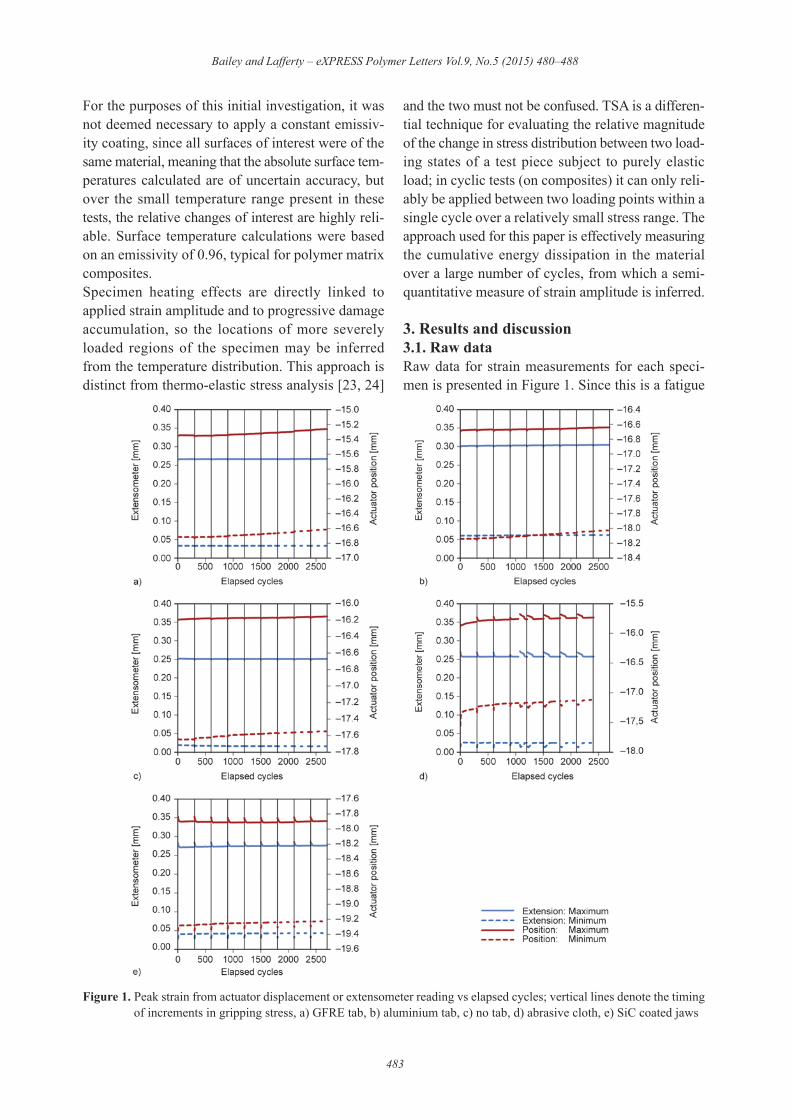
3. Results and discussion3.1. Raw dataRaw data for strain measurements for each speci-men is presented in Figure 1. Since this is a fatigue
Bailey and Lafferty – eXPRESS Polymer Letters Vol.9, No.5 (2015) 480–488
483
Figure 1. Peak strain from actuator displacement or extensometer reading vs elapsed cycles; vertical lines denote the timingof increments in gripping stress, a) GFRE tab, b) aluminium tab, c) no tab, d) abrasive cloth, e) SiC coated jaws

test, the specimen behavior does change with elapsedcycles, hence these charts are presented with cycleson the x-axis; vertical lines are not gridlines, butinstead denote each point at which the hydraulic pres-sure to the grips was increased, by a step or 20 bar.The values of dynamic modulus and phase anglecalculated live with each cycle are plotted in a sim-ilar manner in Figure 2.
3.2. Complex dynamic modulusUnder ideal conditions it is assumed that the speci-men would be gripped such that there is no slippingof the specimen within the jaws, that load is intro-
duced evenly without stress concentrations, and thatthe stiffness of the grip body and actuator are greatlyabove that of the specimen under test. Since our cur-rent standards for composite test coupons are straightand parallel sided, the result of this would be thatany geometry-independent measurement of stiffnesswould ideally be identical when calculated from gripseparation or extensometer respectively. Practically,this is clearly unrealistic, but many workers utilizegrip separation to measure strain, for a variety of rea-sons. For this reason, the authors and many othersources frequently emphasize the importance of strainmeasurement on an appropriate gauge length.
Bailey and Lafferty – eXPRESS Polymer Letters Vol.9, No.5 (2015) 480–488
484
Figure 2. Calculated complex modulus from actuator displacement or extensometer reading vs elapsed cycles; vertical linesdenote the timing of increments in gripping stress, a)!GFRE tab, b)!aluminium tab, c)!no tab, d)!abrasive cloth,e) SiC coated jaws

Figure 3 shows the error in complex modulus gen-erated by imperfect gripping, and how it varies withthe combination of clamping force and tab material.Each data point is the average of the percentage dif-ference between 20 pairs of data points; ‘error bars’on each data point indicate the maximum variationfrom mean.The implication of a negative error is that there is
significant shear or slippage within the gripped sec-tion; the effect of this is equivalent to a specimenwith lower modulus or a larger gauge length. Bycontrast, positive errors suggest a degree of over-constraint on the specimen, causing the ends of thegauge length to exhibit greater on-axis stiffness.Logically it is also possible for a specimen to sufferfrom both effects at the same time; experiencingsome slippage on the loading axis, while the ends ofthe gauge length are still subjected to a degree ofover-constraint. For this reason, it is difficult to inferspecific causality solely from the difference inextension or derived calculations, but it is the firststep in identifying a problem.On this basis it is postulated that the ‘traditional’method of using cross-ply composite tabs results innoticeable over-constraint; potentially this is causedsimply by the fact that the bonded tabs themselvesapply considerable transverse constraint. Furthermorethat this effect dominates compared with the smalldegree of slipping, which is known to happen at verylow grip pressures through the evidence of abradedmaterial which is found stuck in the serrations or thejaw face.Conversely, the use of tab-less specimens (whetherdirectly clamped in serrated, hardened steel jaws, orusing the recommended layer of abrasive cloth) mustgive a significant degree of slipping or not clampthe full grip length. Using the same type of specimen
with a silicon carbide bonded into the metal jawsurface still showed high sensitivity to clampingforce, but surprisingly shifted the errors to a positivedomain.Finally, the use of aluminium tab material seems tobe quite effective in achieving only a small error,without the need for high clamping forces whichincrease the risk of stress concentrations at the endof the gripped section.
3.3. Loss angleFigure 4 shows the additional component of lossangle introduced at the grip, as compared with thatat the extensometer measurement. Each data pointis the average of the difference between 20 pairs ofdata points; ‘error bars’ on each data point indicate themaximum variation from mean. Loss angle (usuallytermed ", or expressed as tan") can be used as a meas-ure of the damping in a system. Since it is known thatthe specimen material is moderately consistent for itswhole length, it must be assumed that a phase dif-ference between the two displacement measurementsis introduced by slipping or shear within the grippingassembly.This appears to confirm the earlier suspicion that thecomposite tabs are held quite effectively, while theun-tabbed specimens experience more significantslippage.It is interesting to note that the specimen with alu-minium tabs introduced a similar degree of lag to theuntabbed specimen, but probably for different rea-sons. With the untabbed specimen this seems verylikely to be related to slippage, but the aluminium tabsappeared securely gripped throughout, so their con-tribution may come from shear within the metal. Itwas not possible to use digital image correlation dur-ing this study to determine the actual displacement
Bailey and Lafferty – eXPRESS Polymer Letters Vol.9, No.5 (2015) 480–488
485
Figure 3. Error in measured complex modulus at grip vsgripping stress on tab (based on actuator displace-ment compared with extensometer measurement)
Figure 4. Additional phase lag introduced in grip vs grip-ping pressure (phase angle at extensometer for alltests was within 0.10±0.05°)

fields, but the authors intend to pursue this in furtherwork to resolve these questions.
3.4. Temperature distributionFigure 5 shows thermal images of the 5 different tab/grip configurations. A localized heating effect nearthe end of the grip is particularly obvious on the spec-imen with conventional composite tabs.It is very clear that in the standard tabbed specimens,there is a very high degree of heating just within theend of the gripped section. The specimen grippedwith un-bonded abrasive cloth behaved similarly.Using integral abrasive surfaces on the jaws, withouttabs, seemed to reduce the sharp peak in heating, butcaused more heat introduction further back into thegrip, possibly due to sliding and abrasion. By con-trast, specimens without tabs, or with aluminium tabs,show very gentle transitions from gripped to freelength.The specimens without any tabs and with aluminiumtabs have remained much cooler that the others, prob-ably due to much better conduction extracting morerapidly the heat which is generated. Since fatigue per-formance of composites is necessarily affected bytemperature, due to the nature of the matrix materials,this would suggests that fatigue test specimens aredoubly likely to fail at the grip, since the material nearthe end of the tab is both more highly stressed and athigher temperature.Figure 6 plots the increase in surface temperaturealong the center-line of these specimens after cyclicloadingIt is very clear that in the standard, composite-tabbedspecimen, there is a very high degree of heating justwithin the end of the gripped section. Despite earlier
indications (see section 3.4) that the tab-less speci-men gripped with un-bonded abrasive cloth sufferssignificant slippage, the thermal activity in this con-figuration is very similar to the standard tabbed spec-imen. The implication of this is that the load introduc-tion and damage localization is very similar betweenthese two configurations. It may be argued that thisis not an unexpected outcome, since these methodswere established as moderately reliable and compa-rable early on in quasi-static test development forcomposites [1]; this would imply that the inducedmechanical behavior of the specimen must be con-gruent in order to achieve similar results.By contrast, specimens without tabs, or with alu-minium tabs, show very gentle transitions fromgripped to free length. It must be recognized thatthese specimens have a more direct connection to themetal jaws, through which heat might be conductedaway into the thermal mass of the grips. Although thiswould surely suppress the magnitude of temperaturerise, any significant local heating effects should stillbe apparent. It would appear that the severity of local
Bailey and Lafferty – eXPRESS Polymer Letters Vol.9, No.5 (2015) 480–488
486
Figure 5. Thermal images of the specimen edge after cyclic loading. (a) GFRE tab; (b) Aluminium tab; (c) Tab-less;(d) Tab-less with abrasive cloth; (e) Tab-less in SiC fused jaws.
Figure 6. Temperature profiles along specimen edge as itenters the grip

heating and grip-induced damage is reduced in thesesolutions, which do not conform to current interna-tional standards.Using jaw faces with a rough silicon carbide surface,fused directly to the steel, with a tab-less specimen,seemed to reduce the sharp peak in heating, butcaused more heat introduction further back within thegrip. This may be due to sliding and abrasion of thesurface, as previously discussed, which might reason-ably overwhelm the better conductive path to extractheat into the jaws.The authors have been unable to identify any otherexperimental analysis of stress or strain concentra-tions in the gripping region of composite test couponsfor in-plane tensile or compressive property meas-urement. However, a survey of stress concentra-tions within the gripped section was conducted byDe Baere et al. [8], using finite element modelling,for a fairly extensive range of tab and grip permuta-tions. For GRFE tabbed specimens, the temperaturerise illustrated by the line scans presented in Figure 6seem to correspond well with the calculated stressconcentrations along the specimen presented in thatstudy. For aluminium tabbed specimens the compu-tational method anticipated a small peak in stress con-centration near the end of the tabs, which is notobserved in the experimental data here, althoughthis effect may be masked by the much better heatconduction along and out of the specimen, as alreadymentioned. De Baere et al. [8] did not examine un-tabbed specimens.During the tests, it was also noted that the tempera-ture distribution appears to change with the applied
clamping stress. As shown in Figure 7, qualitativelyspeaking, higher clamping stress seems to push thelocalized heating into a tighter region, closer to theend of the gripped section, or just beyond it on sometab-less specimens. At the time of writing, insuffi-cient data was available to draw any reliable con-clusions without further testing.
4. ConclusionsThe implication of these data is that, at least in cyclictesting of composites, the standard method of grip-ping composite coupons can easily cause damage andfailure outside the gauge length, under un-representa-tive loading conditions. This initial study gives someclues for how to locate and reduce the problem, andthe findings are in agreement with computationalmodels of stress concentration, as well as anecdotalevidence from a significant number of workers whoregularly observe failure within the gripped sectionof composite fatigue test coupons.The short case study presented here is based on asmall sample size, but the indications are that there isa need to reconsider the best methods for grippingcomposite specimens for fatigue loading. The authorsintend to verify this on a larger sample, and using sev-eral other representative materials.
References [1] Hart-Smith L. J.: Generation of higher composite mate-
rial allowables using improved test coupons. in ‘Pro-ceedings of the 36th International SAMPE Symposium,San Diego, USA’ 1029–1045 (1991).
[2] Hojo M., Sawada Y., Miyairi H.: Influence of clamp-ing method on tensile properties of unidirectionalCFRP in 0° and 90° directions – Round Robin activityfor international standardization in Japan. Composites,25, 786–796 (1994).DOI: 10.1016/0010-4361(94)90139-2
[3] ASTM D3039/D3039M-14: Standard test method fortensile properties of polymer matrix composite materi-als (2014).
[4] Becerra N.: Flight mission. Testing, testing. MaterialsWorld, 22, 26–27 (2014).
[5] Bailey P. B. S.: Growth in dynamic testing market forcomposites. Advanced Materials and Processes, 172,17–21 (2014).
[6] BS EN ISO 527-5: Plastics. Determination of tensileproperties. Test conditions for unidirectional fibre-rein-forced plastic composites (2009).
[7] Morrell, R., McCartney L. N.: Measurement of proper-ties of brittle-matrix composites. British Ceramic Trans-actions, 92, 1–7 (1993).
Bailey and Lafferty – eXPRESS Polymer Letters Vol.9, No.5 (2015) 480–488
487
Figure 7. Temperature distribution on GFRE tab specimen(a) after 1600 cycles with 30 MPa clamping stressand (b) after a further 2100 cycles at 120 MPaclamping stress

[8] De Baere I., Van Paepegema W., Degrieck J.: On thedesign of end tabs for quasi-static and fatigue testing offibre-reinforced composites. Polymer Composites, 30,381–390 (2008).
[9] Kawai M., Morishita M., Satoh H., Tomura S.: Effectsof end-tab shape on strain field of unidirectional car-bon/epoxy composite specimens subjected to off-axistension. Composites Part A: Applied Science and Man-ufacturing, 28, 267–275 (1997).DOI: 10.1016/S1359-835X(96)00122-4
[10] Sun C. T., Chung I.: An oblique end-tab design fortesting off-axis composite specimens. Composites, 24,619–623 (1993).DOI: 10.1016/0010-4361(93)90124-Q
[11] Curtis P.: CRAG test methods for the measurement ofthe engineering properties of fibre reinforced plastics.Technical Report 88012. Royal Aerospace Establish-ment, Farnborough (1988).
[12] De Baere I., Van Paepegem W., Quaresimin M.,Degrieck J.: On the tension–tension fatigue behaviourof a carbon reinforced thermoplastic Part I: Limitationsof the ASTM D3039/D3479 standard. Polymer Test-ing, 25, 625–632 (2011).DOI: 10.1016/j.polymertesting.2011.05.004
[13] De Baere I., Van Paepegem W., Hochard C., Degrieck J.:On the tension–tension fatigue behaviour of a carbonreinforced thermoplastic Part II: Evaluation of a dumb-bell-shaped specimen. Polymer Testing, 30, 663–672(2011).DOI: 10.1016/j.polymertesting.2011.05.005
[14] Curtis D. C., Moore D. R., Slater B., Zahlan N.: Fatiguetesting of multi-angle laminates of CF/PEEK. Com-posites, 19, 446–452 (1988).DOI: 10.1016/0010-4361(88)90702-1
[15] Xiao J., Bathias C.: Fatigue behaviour of unnotched andnotched woven glass/epoxy laminates. Composites Sci-ence and Technology, 50, 141–148 (1994).DOI: 10.1016/0266-3538(94)90135-X
[16] Patrick M., Norman T. L.: Effect of notch on failure oftwo-dimensional ±45° triaxial braided textile compos-ite materials. ASTM Journal of Composites Technologyand Research, 16, 262–269 (1994).
[17] ASTM D7615/D7615M-11: Standard practice for open-hole fatigue response of polymer matrix compositelaminates (2011).
[18] Spearing S. M., Beaumont P. R. W.: Fatigue damagemechanics of composite materials. I: Experimentalmeasurement of damage and post-fatigue properties.Composites Science and Technology, 44, 159–168(1992).DOI: 10.1016/0266-3538(92)90109-G
[19] Liu C., Cheng L., Luan X., Li B., Zhou J.: Damageevolution and real-time non-destructive evaluation of2D carbon-fiber/SiC-matrix composites under fatigueloading. Materials Letters, 62, 3922–3944 (2008).DOI: 10.1016/j.matlet.2008.04.063
[20] Ogasawara T., Onta K., Ogihara S., Yokozeki T., HaraE.: Torsion fatigue behavior of unidirectional carbon/epoxy and glass/epoxy composites. Composite Struc-tures, 90, 482–489 (2009).DOI: 10.1016/j.compstruct.2009.04.023
[21] Bailey P. B. S., Hoehl C., Jamshidi P., Cowan C., SquiresS., Smith A. J.: Enhanced fatigue testing of compos-ites. in ‘Proceedings of the 19th International Confer-ence on Composite Materials, Montreal, Canada’ 5033–5038 (2013).
[22] Toubal L., Karama M., Lorrain B.: Damage evolutionand infrared thermography in woven composite lami-nates under fatigue loading. International Journal ofFatigue, 28, 1867–1872 (2006).DOI: 10.1016/j.ijfatigue.2006.01.013
[23] Baker L. R., Webber J. M. B.: Thermoelastic stressanalysis. Optica Acta: International Journal of Optics,29, 555–563 (1982).DOI: 10.1080/713820858
[24] Fruehmann R. K., Dulieu-Barton J. M., Quinn S.:Assessment of fatigue damage evolution in woven com-posite materials using infra-red techniques. Compos-ites Science and Technology, 70, 937–946 (2010).DOI: 10.1016/j.compscitech.2010.02.009
Bailey and Lafferty – eXPRESS Polymer Letters Vol.9, No.5 (2015) 480–488
488


