eP02-02 alarm engineering RC1012 - Siemens Automation and Drive Technologies - SCE TIA Training...
31
Industry Automation and Drive Technologies - SCE TIA Training Manual Page 1 of 31 Module P02_02 Status: 12/2010 PCS 7 for Universities ALARM ENGINEERING OBJECTIVE In this instruction module, students learn the fundamentals of a signaling system. They understand the purpose and the areas of use of alarm and signaling systems, and know the requirements resulting from this for such systems. They are acquainted with the possibilities of representing messages and alarms, and interacting with them. Based on this, the students are able to design an alarm management that is appropriate to and suitable for use in PCS7. THEORY IN SHORT Signaling systems play an extremely important part in economically operating process engineering plants. Designed ergonomically, they inform the operator specifically of unintentional deviations in the process state from a defined normal state (refer also to the chapter ’Functional Safety). Signaling systems make it possible for the operator to directly locate the cause of the fault and through adapted intervention, adjust the process control strategy in such a way that despite the fault, specification-conforming products can continue to be manufactured, or the process is stabilized in such a way that the fault causes a minimum of production outage. The control system PCS7 includes a number of technical resources to implement a signaling system. The palette ranges from function blocks for generating messages, icons for representing alarm states, group alarms along the plant hierarchy to components for representing and managing messages in lists (refer to Figure 1). Based on this and by taking note of a number of design rules for the intended purpose of message texts and for the assignment of priorities, we can implement very efficiently an effective signaling system that meets all the requirements of the presently valid national and international standards and guidelines. Figure 1: From alarm block to visualization at alarm lists
-
Upload
hoangtuyen -
Category
Documents
-
view
214 -
download
0
Transcript of eP02-02 alarm engineering RC1012 - Siemens Automation and Drive Technologies - SCE TIA Training...

Industry Automation and Drive Technologies - SCE
TIA Training Manual Page 1 of 31 Module P02_02 Status: 12/2010 PCS 7 for Universities
ALARM ENGINEERING
OBJECTIVE
In this instruction module, students learn the fundamentals of a signaling system. They understand the purpose and the areas of use of alarm and signaling systems, and know the requirements resulting from this for such systems. They are acquainted with the possibilities of representing messages and alarms, and interacting with them. Based on this, the students are able to design an alarm management that is appropriate to and suitable for use in PCS7.
THEORY IN SHORT
Signaling systems play an extremely important part in economically operating process engineering plants. Designed ergonomically, they inform the operator specifically of unintentional deviations in the process state from a defined normal state (refer also to the chapter ’Functional Safety). Signaling systems make it possible for the operator to directly locate the cause of the fault and through adapted intervention, adjust the process control strategy in such a way that despite the fault, specification-conforming products can continue to be manufactured, or the process is stabilized in such a way that the fault causes a minimum of production outage.
The control system PCS7 includes a number of technical resources to implement a signaling system. The palette ranges from function blocks for generating messages, icons for representing alarm states, group alarms along the plant hierarchy to components for representing and managing messages in lists (refer to Figure 1).
Based on this and by taking note of a number of design rules for the intended purpose of message texts and for the assignment of priorities, we can implement very efficiently an effective signaling system that meets all the requirements of the presently valid national and international standards and guidelines.
Figure 1: From alarm block to visualization at alarm lists

Industry Automation and Drive Technologies - SCE
TIA Training Manual Page 2 of 31 Module P02_02 Status: 12/2010 PCS 7 for Universities
THEORY
SIGNALING SYSTEMS Because of the consistent usage of modern process control, process engineering plants are automated to a high degree and optimized with respect to safety. For that reason, the operator of such a plant monitors a largely automated process that requires operator action only when, because of a process or the plant fault, manual intervention is required. The objective of such manual interventions always is to take the process back to its normal state (refer also to the chapter 'Functional Safety’) before the automatic safety devices are activated.
Since in general, safety devices take the monitored technical facility to a safe state, this action causes as a rule either a loss in product quality, production delays or even the standstill of the entire production. This has considerable negative effects on the profitability of the plant. For that reason, the danger -that an impermissible fault activates a protective device- should be detected early so that the fault can be prevented by suitable manual intervention. In addition, the operator should be informed that if a safety device is activated, he can monitor the consequences.
The signaling system in this case serves as the central interface between the operator and the monitored process, and makes all facilities for managing messages and alarms in the control system available [2]. It allows the operator to detect deviations from setpoints in the area of the intended operation early and to specifically counteract them.
shows the four phases of interaction between the operator and the signaling system of the process control system.
That means, the signaling system has to make it possible for the operator to suitably react to an event that was signaled. To accomplish this, the system has to meet a number of requirements. Indications and alarms have to be represented clearly arranged, transparent and consistent.
The operator has to be supported regarding the situation-oriented evaluation of an indication or an alarm as well as regarding the selection of a suitable operator intervention. To this end, always a suitable action prompt has to be provided, depending on the process state.
To prevent the operator being overburdened, the number as well as the frequency of indications and alarms has to be minimized. In addition, the work load should be kept as low as possible for the operator while indications and alarms occur. Beyond this, the
Alarm System of DCS
Operator
Representation
Generation
Assessment
Operator Action
Process Equipment

Industry Automation and Drive Technologies - SCE
TIA Training Manual Page 3 of 31 Module P02_02 Status: 12/2010 PCS 7 for Universities
operator can be supported in his work through suitable tools for documenting and evaluating indications and alarms.
When designing a signaling system, the limits of the performance capability of the later operators have to be taken into account. The total number of tasks that a signaling system requires an operator to handle and that have to be mastered must not exceed human capability limits either short term or permanently.
On the one hand, a brief sharp rise in the number or the rate of alarms can cause the operator to be briefly overloaded (alarm surge). It should be noted that on the average, an operator can not process more than a maximum of seven items of information at the same time (7± rule).
On the other hand, a continuously high workload -caused by a constantly large number of arriving alarms- can cause the operator to be permanently overstrained. This leads to a growing decrease of the operator’s performance capability and reliability.
A signaling system has to be designed in a way that it utilizes the characteristic attributes of human perception, and takes their limits into account. Important alarms have to be emphasized in order to be noticed quickly. Events that occur rarely have to be presented in a special way to attract the attention of the user. Important information should be presented redundantly, to facilitate it being noticed. In addition, several sensory channels should be addressed if at all possible to convey the information (for example, acoustical warning signals).
Only when a signaling system meets these requirements is it actually supporting the operator in his task to control and monitor the plant.
ALARMS AND INDICATIONS
Signaling systems are used to manage indications and alarms in control systems. Indication means in general any report and any indication of the occurrence of a specific event. However, in a narrower sense, the term is used only for those indications that do not require the operator to respond immediately[1]. Otherwise, the term Alarm is used. That is, the term indication is used as a general term as well as a specific term. Below, the following definitions are used consistently:
– Alarm: Indication or report of the occurrence of an event that requires immediate operator reaction. The reaction may be an activity, such as performing an operation. However, the reaction may be exclusively mental; for example, increased attention.
– Indication: Indication or report of the occurrence of an event that does not require the operator’s immediate reaction.
Alarms signal deviations of the process or of the plant from the setpoint and thus make it possible for the operator to avert a hazardous situation or economic damage. To perform this task, good alarms have to have the following features [3]:
– relevant: The alarm is justified and valuable to the operator.
– clear: The alarm contains information for the operator. It does not repeat any other alarm.
– timely: The alarm arrives timely if intervention is required. But it arrives early enough that the operator can still intervene.
– prioritized: The alarm provides an indication how urgent the operator’s reaction is.
– understandable: The alarm contains information that can be understood clearly and easily.
– diagnostic: The alarm allows the operator to diagnose the problem.
– directional: The alarm provides suitable action instructions for solving the problem that occurred.
– focusing: The alarm guides the attention to the most important problems.
Alarms should always be used purpose-oriented. It has to be clarified what is monitored, how monitoring is carried out and when an alarm is triggered. In addition, we have to

Industry Automation and Drive Technologies - SCE
TIA Training Manual Page 4 of 31 Module P02_02 Status: 12/2010 PCS 7 for Universities
define how the operator can react to an alarm. Based on these criteria, alarms can be subdivided into numerous types (refer to [3]). The most important alarm types are:
– Absolute alarm: The alarm is generated when a specified limit is exceeded or dropped below.
– Time delayed alarm: The alarm is generated when the alarm criterion for a specified time span is met.
– Control engineering alarm: The control system itself generates an alarm signal that requires immediate operator reaction.
ALARM PROCESSING BY THE OPERATOR
The operator processes the alarms in three phases: First, the operator has to recognize that a problem occurred (1st phase: Recognition). To this end, the signaling system has to turn the operator’s attention to the problem. Then, with the aid of the control system, the operator has to identify the problem. (2nd phase: Identification). After the operator located the cause, he can initiate steps to eliminate the fault and compensate for the consequences of the problem (3rd phase: Troubleshooting). During each of these phases the signaling system has to be able to suitably support the operator. Table 1 lists the most important capabilities of the signaling system to provide that support.
Table 1: Options of the alarm system to support the processing of alarms
Phase Supporting options of the alarm system
Recognition – Effective guidance of attention
– Suitable presentation of information
– Pre-processing and sampling information
Identification – Significant description of errors
– Tools for investigation of errors
– Jumping to the appropriate operator display of PCS
Troubleshooting – Significant instructions for solving the problem
– Jumping to the appropriate operator display of PCS for operator intervention
To make alarm processing possible to the plant operator in a way that makes sense, occurring alarms have to be suitably managed by the signaling system. Alarm management supports all phases of the interaction between the operator and the signaling system of the process control system.

Industry Automation and Drive Technologies - SCE
TIA Training Manual Page 5 of 31 Module P02_02 Status: 12/2010 PCS 7 for Universities
<<this page is blank>>
Industry Automation and Drive Technologies - SCE
TIA Training Manual Page 6 of 31 Module P02_02 Status: 12/2010 PCS 7 for Universities
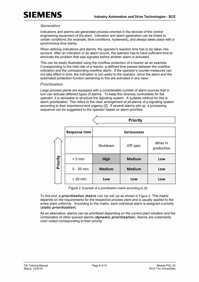
Generation Indications and alarms are generated process-oriented in the devices of the control engineering equipment of the plant. Indication and alarm generation can be linked to certain conditions (for example, time conditions, hysteresis), and always takes place with a synchronous time stamp.
When defining indications and alarms, the operator’s reaction time has to be taken into account. After an indication or an alarm occurs, the operator has to have sufficient time to eliminate the problem that was signaled before another alarm is activated.
This can be easily illustrated using the overflow protection of a reactor as an example. Corresponding to the inlet rate of a reactor, a defined time passes between the overflow indication and the corresponding overflow alarm. If the operator’s counter-measures can not take effect in time, the indication is not useful to the operator, since the alarm and the automated protection function pertaining to this are activated in any case.
Prioritization
Large process plants are equipped with a considerable number of alarm sources that in turn can activate different types of alarms. To keep this diversity controllable for the operator, it is advisable to structure the signaling system. A suitable method for this is alarm prioritization. This refers to the clear arrangement of all alarms of a signaling system according to their importance and urgency [2]. If several alarms pile up, a processing sequence can be suggested to the operator based on alarm priorities.
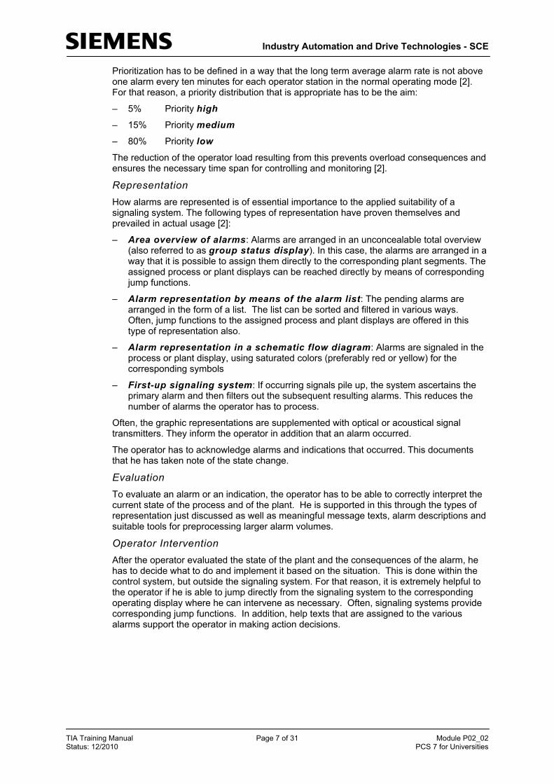
Figure 2: Example of a prioritization matrix according to [2]
To this end, a prioritization matrix can be set up as shown in Figure 2. This matrix depends on the requirements for the respective process plant and is usually applied to the entire plant uniformly. According to this matrix, each individual alarm is assigned a priority (static prioritization).
As an alternative, alarms can be prioritized depending on the current plant situation and the combination of other queued alarms (dynamic prioritization). Alarms are customarily color coded corresponding to their priority.
Response time
Shutdown Off specdelay in
production
< 5 min High Medium Low
5 - 20 min Medium Medium Low
> 20 min Low Low Low
Seriousness
Priority
Pri
ori
ty
Industry Automation and Drive Technologies - SCE
TIA Training Manual Page 7 of 31 Module P02_02 Status: 12/2010 PCS 7 for Universities
Prioritization has to be defined in a way that the long term average alarm rate is not above one alarm every ten minutes for each operator station in the normal operating mode [2]. For that reason, a priority distribution that is appropriate has to be the aim:
– 5% Priority high
– 15% Priority medium
– 80% Priority low
The reduction of the operator load resulting from this prevents overload consequences and ensures the necessary time span for controlling and monitoring [2].
Representation How alarms are represented is of essential importance to the applied suitability of a signaling system. The following types of representation have proven themselves and prevailed in actual usage [2]:
– Area overview of alarms: Alarms are arranged in an unconcealable total overview (also referred to as group status display). In this case, the alarms are arranged in a way that it is possible to assign them directly to the corresponding plant segments. The assigned process or plant displays can be reached directly by means of corresponding jump functions.
– Alarm representation by means of the alarm list: The pending alarms are arranged in the form of a list. The list can be sorted and filtered in various ways. Often, jump functions to the assigned process and plant displays are offered in this type of representation also.
– Alarm representation in a schematic flow diagram: Alarms are signaled in the process or plant display, using saturated colors (preferably red or yellow) for the corresponding symbols
– First-up signaling system: If occurring signals pile up, the system ascertains the primary alarm and then filters out the subsequent resulting alarms. This reduces the number of alarms the operator has to process.
Often, the graphic representations are supplemented with optical or acoustical signal transmitters. They inform the operator in addition that an alarm occurred.
The operator has to acknowledge alarms and indications that occurred. This documents that he has taken note of the state change.
Evaluation
To evaluate an alarm or an indication, the operator has to be able to correctly interpret the current state of the process and of the plant. He is supported in this through the types of representation just discussed as well as meaningful message texts, alarm descriptions and suitable tools for preprocessing larger alarm volumes.
Operator Intervention
After the operator evaluated the state of the plant and the consequences of the alarm, he has to decide what to do and implement it based on the situation. This is done within the control system, but outside the signaling system. For that reason, it is extremely helpful to the operator if he is able to jump directly from the signaling system to the corresponding operating display where he can intervene as necessary. Often, signaling systems provide corresponding jump functions. In addition, help texts that are assigned to the various alarms support the operator in making action decisions.

Industry Automation and Drive Technologies - SCE
TIA Training Manual Page 8 of 31 Module P02_02 Status: 12/2010 PCS 7 for Universities
ALARM MANAGEMENT IN PCS7
PCS7 provides a high performance signaling system. It informs the plant operator about occurring events and displays them in the process mode in the form of signal lists and a group display. Another list indicates the interventions by the plant operator. The display for signals is configured in WinCC.
PCS7 differentiates three different event classes [4]:
– Control engineering indications: in PCS7 they are generated by driver blocks when they detect errors at their own components (AS, OS, etc.). These indications don’t have to be configured.
– Process indications: they signal events of the automated process, such as limit violations and process indications. These indications don’t have to be configured. However, message texts and signaling priority can be changed if needed.
– Operator input messages: are generated when process variables are operated; for example, when the operating mode is switched. Operator input messages are generated automatically if the picture blocks in the PCS7 Library are used, or one’s own blocks that are configured in conformance with PCS7.
Indications for the AS and the IO are configured within the scope of setting up CFCs, or in the process object view. It is possible to change indications of block types or individual block instances, and to configure one’s own message texts. SFCs, types and instances are also able to generate indications.
Indications for the OS are configured by using the application Alarm Logging in WinCC Explorer. There, the triggering event for an indication is specified also.
When indications are configured, different aspects have to be taken into account. The most important aspects are discussed below:
– Message text: Blocks with signaling behavior have preset message texts with the corresponding event class and event type. These texts and attributes can be adapted depending on requirements. In addition, information from the process or block comments can be added to the message text as associated values.
– Signal number: During compilation, each signal configured in the ES is assigned a unique signal number automatically in alarm logging. The signal number range is specified when the project is set up. Signal numbers are assigned uniquely either project-wide or CPU-wide. The latter is the precondition for assigning signal priorities.
– Signal priority: A signal can be assigned a priority between 0 (lowest) and 16 (highest). Signal lists can be sorted and filtered according to their priority. In the message line in the overview area, always the indication is shown that has the highest priority and has not yet been acknowledged.
Plant blocks that are visualized on the OS have the function Loop-In-Alarm. In the case of process and control engineering alarms, this function allows for changing to the corresponding picture block directly from the signal list.
PCS7 uses a central acknowledgement concept. If a signal is acknowledged on an OS, the acknowledgement is first sent to the triggering block, and from there to all additional relevant OSs.
LITERATURE
[1] VDI 3699 (Edition. 2005-05): Process Control with Display Screens.
[2] NAMUR NA 102 (Edition. 2005-12): Alarm Management.
[3] c 191 (Edition. 2007-10): Alarm Systems.
[4] SIEMENS (2009): Process Control System PCS7: Engineering System (V7.1).

Industry Automation and Drive Technologies - SCE
TIA Training Manual Page 9 of 31 Module P02_02 Status: 12/2010 PCS 7 for Universities
STEP BY STEP INSTRUCTIONS
TASK
This task requires setting up alarms and warnings for the operator station (OS). As an example, we are programming filling level monitoring for reactor A1T2R001. The alarms and warnings set up there will be indicated in WinCC.
OBJECTIVE
In this chapter, the students
– Learn to integrate monitoring blocks and alarm blocks in the CFC
– Get to know WinCC
– Learn to represent alarms and warnings in the operator station (OS)
– Get to know additional functions in the WinCC Graphics Designer
PROGRAMMING
1. To program filling level monitoring, first we open the already existing CFC A1T2L001 for the level of reactor A1T2R001.
( A1_multipurpose_plant T2_reaction A1T2L001 A1T2L001)

Industry Automation and Drive Technologies - SCE
TIA Training Manual Page 10 of 31 Module P02_02 Status: 12/2010 PCS 7 for Universities
2. On the second sheet of the CFC, we then insert -from the folder ’CONTROL’ of the PCS7 Library V71- in the library catalog the block MEAS_MON.
( Libraries PCS7 Library V71 Blocks+Templates/Blocks CONTROL MEAS_MON)
Note: Block MEAS_MON is used to monitor a measuring value (analog signal) for the limit pairs:
– Warning limit (high/low)
– Alarm limit (high/low)
!

Industry Automation and Drive Technologies - SCE
TIA Training Manual Page 11 of 31 Module P02_02 Status: 12/2010 PCS 7 for Universities
3. Next, we rename the MEAS_MON block to ’Monitor_A1T2L001’. Then, the values at inputs ’U_AH’, ’U_WH’, ’U_WL’ and ’U_AL’ are changed as shown here, and input ’U’ is connected to output ’V/Process value’ of block LISA+_A1T2L001 from the first sheet.
( Monitor_A1T2L001 U_AH: 1000.0 U_WH: 900.0 U_WL:150.0 U_AL:
50.0 U V/Process value)

Industry Automation and Drive Technologies - SCE
TIA Training Manual Page 12 of 31 Module P02_02 Status: 12/2010 PCS 7 for Universities
4. So that later in the operator station (OS), the level is indicated with the correct unit we are opening the object properties of the MEAS_MON block. Then, under Connections, we enter the unit ’ml’ at ’U’.
( Object Properties Connections Name: U Unit: ml OK)

Industry Automation and Drive Technologies - SCE
TIA Training Manual Page 13 of 31 Module P02_02 Status: 12/2010 PCS 7 for Universities
Here, all changes in chart ’A1T2L001Sheet2’ are listed once more:
Table 2: New Blocks in Chart ’A1T2L001Blatt2’
Block Catalog/Folder Number of Connections
MEAS_MON / Monitoring measured values
Libraries/PCS7 Library V71/ Blocks+Templates\Blocks/CONTROL
Table 3: Input Wiring in Chart ’A1T2L001Sheet2’
Input Connected to Inverted
MEAS_MON.Monitor_A1T2L001.U
A1T2L001(A,1) / CH_AI.LISA+_A1T2L001.V Process value
MEAS_MON.Monitor_A1T2L001.U_AH
1000.0
MEAS_MON.Monitor_A1T2L001.U_WH
900.0
MEAS_MON.Monitor_A1T2L001.U_WL
150.0
MEAS_MON.Monitor_A1T2L001.U_AL
50.0
Table 4: Changes at the block properties in Chart ’A1T2L001Sheet2’
Name of Connection Changes
MEAS_MON.Monitor_A1T2L001.U
Enter unit ’ml’
Table 5: Output Wiring in Chart ’A1T2L001Sheet2’
Output Connection to Inverted
None None None

Industry Automation and Drive Technologies - SCE
TIA Training Manual Page 14 of 31 Module P02_02 Status: 12/2010 PCS 7 for Universities
5. To compile and download the AS and OS at the same time, highlight the project in the component view of the SIMATIC Manager. Then, select for the PLC ’Compile and Download’
( SCE_PCS7_Prj PLC Compile and Download Objects)

Industry Automation and Drive Technologies - SCE
TIA Training Manual Page 15 of 31 Module P02_02 Status: 12/2010 PCS 7 for Universities
6. Next, we select -as shown here- the objects to be compiled and start the process as
we learned it in the previous chapters. ( Start)
7. After a successful compilation, we open the OS. ( OS(1) Open Object)

Industry Automation and Drive Technologies - SCE
TIA Training Manual Page 16 of 31 Module P02_02 Status: 12/2010 PCS 7 for Universities
8. Within WinCC, in the Graphics Designer we open the picture ’T2_reaction.Pdl’.
( Graphics Designer T2_reaction.Pdl)
9. In this picture, the block icon for the MEAS-MON block ’Monitor_A1T2L001’ was already set up through the compilation run. We are positioning it to the right of the reactor, and save the picture.
( A1T2L001 )
Industry Automation and Drive Technologies - SCE
TIA Training Manual Page 17 of 31 Module P02_02 Status: 12/2010 PCS 7 for Universities
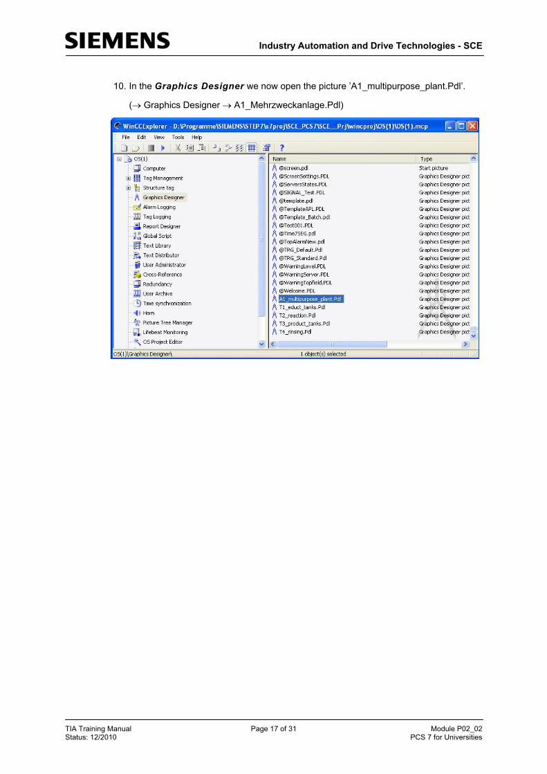
10. In the Graphics Designer we now open the picture ’A1_multipurpose_plant.Pdl’.
( Graphics Designer A1_Mehrzweckanlage.Pdl)
Industry Automation and Drive Technologies - SCE
TIA Training Manual Page 18 of 31 Module P02_02 Status: 12/2010 PCS 7 for Universities
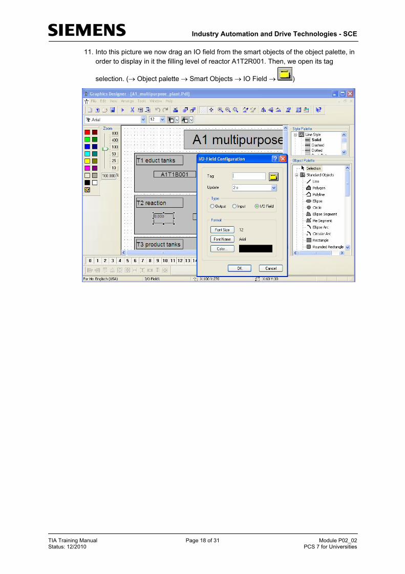
11. Into this picture we now drag an IO field from the smart objects of the object palette, in order to display in it the filling level of reactor A1T2R001. Then, we open its tag
selection. ( Object palette Smart Objects IO Field )

Industry Automation and Drive Technologies - SCE
TIA Training Manual Page 19 of 31 Module P02_02 Status: 12/2010 PCS 7 for Universities
12. Within the tag selection, we select as data source the ES variables. After that, we see in the left window the hierarchy of our project. Here, we can easily locate our MEAS_MON block ’Monitor_A1T2L001’. To display it in the IO field, we select the connection ’U’.
( ES Variables SCE_Plant A1_multipurpose_plant T2_reaction
A1T2L001 A1T2L001 Monitor_A1T2L001 U OK)
13. This tag is now displayed in the configuration dialog. After the following changes, we accept this configuration.
( Update: Upon change Type: Output OK)

Industry Automation and Drive Technologies - SCE
TIA Training Manual Page 20 of 31 Module P02_02 Status: 12/2010 PCS 7 for Universities
14. At the Properties, we are setting the output format to 4 positions in front of the comma, without decimal positions.
( Properties Output/Input Output Format 9999 OK)
15. Then, the following font attributes are selected.
( Properties Font X Alignment: right Y-Alignment: centered)

Industry Automation and Drive Technologies - SCE
TIA Training Manual Page 21 of 31 Module P02_02 Status: 12/2010 PCS 7 for Universities
16. To be able to better interpret the value in runtime, we are entering a tooltip text.
( Properties Other TooltipText: filling level reactor A1T2R001)
17. Then, the IO field -as shown here- is placed below reactor A1T2R001 and two texts
are generated next to it. ( Object Palette StaticText)

Industry Automation and Drive Technologies - SCE
TIA Training Manual Page 22 of 31 Module P02_02 Status: 12/2010 PCS 7 for Universities
18. Below educt tank A1T1B003, a display is to be implemented with a text list that indicates whether this tank is empty or not. After we dragged it from the Object Palette into the picture, we open its tag selection.
( Object Palette Smart Objects IO Field )
19. Within the tag selection, this time we select ’STEP 7 Symbol Server’. After that, we see in the left window the symbols of our S7 program. Here, we select input I3.1 ’A1.T1.A1T1L003.LSA-.SA-’.
( STEP 7 Symbol Server S7 Program(1) Symbols I3.1
’A1.T1.A1T1L003.LSA-.SA-’ OK)

Industry Automation and Drive Technologies - SCE
TIA Training Manual Page 23 of 31 Module P02_02 Status: 12/2010 PCS 7 for Universities
20. This tag is then displayed in the configuration dialog. After the following changes, we accept this configuration.
( Update: Upon change Field Type: Output OK)
21. The representation of the font is set in the properties of the text list.
( Properties Font X Alignment: centered Y Alignment: centered)

Industry Automation and Drive Technologies - SCE
TIA Training Manual Page 24 of 31 Module P02_02 Status: 12/2010 PCS 7 for Universities
22. The texts are assigned to the values of the variable in the Properties also. (
Properties Output/Input Assignments)
23. The indication ’EMPTY’ is assigned to value 0 and ’OK’ to value 1.
( Range type: Single Value Value range: 0 Text: Empty Change Range
type: Single Value Value range: 1 Text: OK Append OK )

Industry Automation and Drive Technologies - SCE
TIA Training Manual Page 25 of 31 Module P02_02 Status: 12/2010 PCS 7 for Universities
24. We need just such a text list a second time for a textual display below product tank A1T3B001. It indicates whether this tank is full or not. To this end, the text list that was
already generated is highlighted and duplicated. ( Duplicate)
25. For product tank A1T3B001 we select input I12.1 ’A1.T3.A1T3L001.LSA+.SA+’.
( STEP 7 Symbol Server S7 Program(1) Symbols I12.1
’A1.T3.A1T3L001.LSA+.SA+’ OK)

Industry Automation and Drive Technologies - SCE
TIA Training Manual Page 26 of 31 Module P02_02 Status: 12/2010 PCS 7 for Universities
26. Now, we are changing the assignment at the Properties. This time, ’OK’ is assigned to value 0 and ’Full’ to value 1.
( Range type: Single Value Value range: 0 Text: OK Change Range type:
Single Value Value range: 1 Text: FULL Change OK)
27. Now, the second text list is placed below product tank A1T3B001 and the picture is
saved. ( )

Industry Automation and Drive Technologies - SCE
TIA Training Manual Page 27 of 31 Module P02_02 Status: 12/2010 PCS 7 for Universities
28. Here, the representation of a warning in runtime is shown. In the message line, the warning or alarm that occurred last and has not been acknowledged yet appears. If the operator wants to switch directly to the picture where it was triggered, he has two options:
– With the button Loop in Alarm in the message line
– With a click on the disturbance indication in the display hierarchy
( )
Industry Automation and Drive Technologies - SCE
TIA Training Manual Page 28 of 31 Module P02_02 Status: 12/2010 PCS 7 for Universities
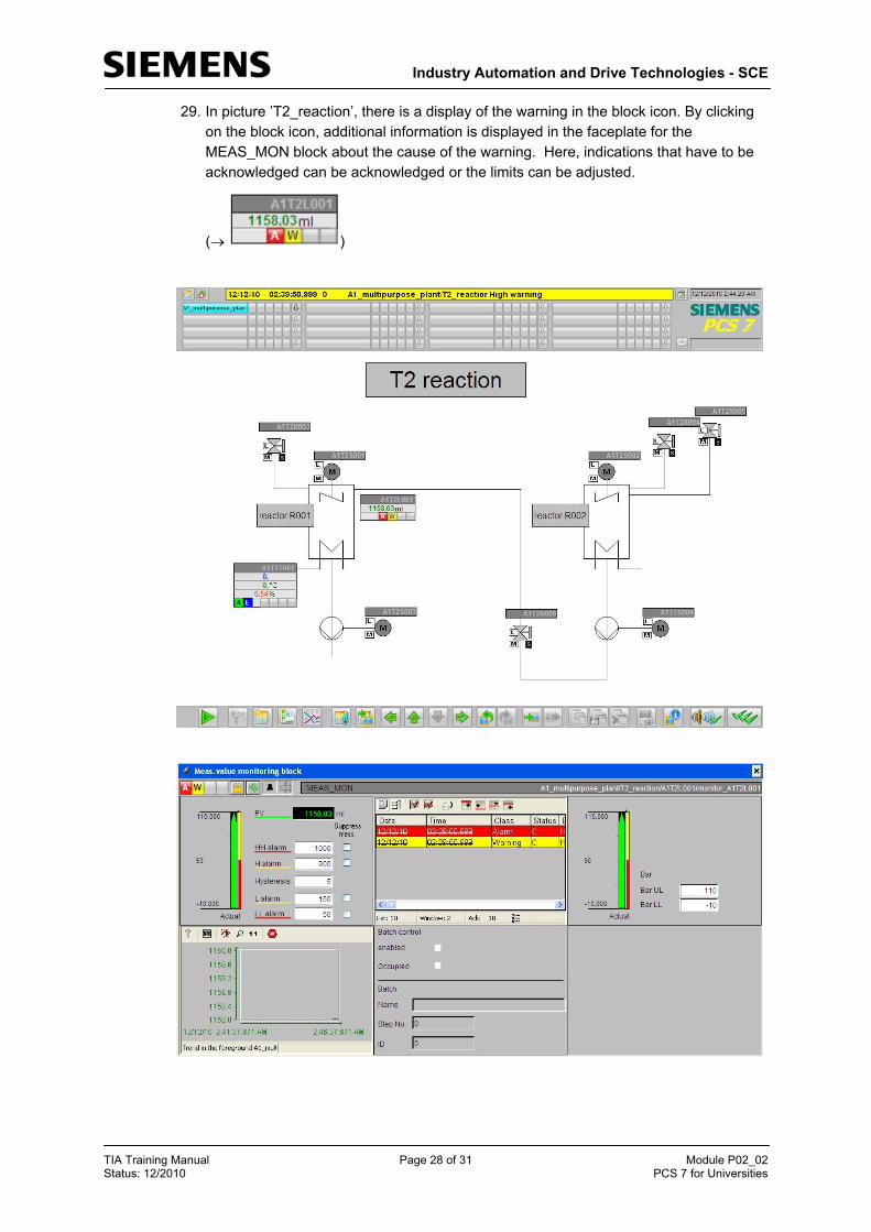
29. In picture ’T2_reaction’, there is a display of the warning in the block icon. By clicking on the block icon, additional information is displayed in the faceplate for the MEAS_MON block about the cause of the warning. Here, indications that have to be acknowledged can be acknowledged or the limits can be adjusted.
( )

Industry Automation and Drive Technologies - SCE
TIA Training Manual Page 29 of 31 Module P02_02 Status: 12/2010 PCS 7 for Universities
30. By clicking on the button Signaling System in the message line, all pending
indications are displayed. ( )

Industry Automation and Drive Technologies - SCE
TIA Training Manual Page 30 of 31 Module P02_02 Status: 12/2010 PCS 7 for Universities
31. By clicking on the button ’Signaling System’ on the key set, we can switch to the complete display of the signaling system. Here, selection options are provided for displaying the indications according to different filter criteria. Below, the chronicle list is
shown. ( )

Industry Automation and Drive Technologies - SCE
TIA Training Manual Page 31 of 31 Module P02_02 Status: 12/2010 PCS 7 for Universities
EXERCISES
We are going to apply what we learned in the theory chapters and the step by step instructions to the exercises. To this end, we are using the already existing multi-project from the step by step instructions (PCS7_SCE_0202_R1009.zip) and expand it.
In the step by step instructions, again only one line of the plant was implemented. For that reason, the objective of the exercise is to implement the missing line. The tasks are to be an aid to generate all necessary plant parts in the WinCC application.
TASKS
The tasks below are based on the step by step instructions. The corresponding steps in the instructions can be used as an aid for each of the exercises.
1. Implement a MEAS_MON block for the temperature in A1T2T001. As a basis, use the MEAS_MON block for the filling level in A1T2L001 that was set up in the step by step instructions. As the high limit for the alarm, ’60.0’ is to be set, and as the high limit for the warning ’55.0’. After you have compiled the PLC program, place the automatically generated block icon in picture ’T2_reaction.pdl’ at a suitable location.
2. Open the picture ’A1_multipurpose_plant.pdl’ and generate two more text lists for the educt tanks A1T1B001 and A1T1B002. As in the case of tank A1T1B003, these text lists are to indicate whether the educt tanks are empty or not.


![EP02 - vsprom.comvsprom.com/images/page/reduktory/PDF/ep02.pdf · 2) Il newton [N] è la forza che imprime a un corpo di massa 1 kg l’accelerazione di 1 m/s 2. 3) Il kilogrammo](https://static.fdocuments.us/doc/165x107/5c6829db09d3f2ff5a8d10cb/ep02-2-il-newton-n-e-la-forza-che-imprime-a-un-corpo-di-massa-1-kg-laccelerazione.jpg)