Eos Electrical System Design and Function
64
Service Training Self Study Program 871603 Eos Electrical System Design and Function
Transcript of Eos Electrical System Design and Function

Service Training
Self Study Program 871603
Eos Electrical System Design and Function

Volkswagen of America, Inc.Volkswagen AcademyPrinted in U.S.A.Printed 06/2006Course Number 871603
©2006 Volkswagen of America, Inc.
All rights reserved. All information contained in this manual is based on the latest information available at the time of printing and is subject to the copyright and other intellectual property rights of Volkswagen of America, Inc., its affi liated companies and its licensors. All rights are reserved to make changes at any time without notice. No part of this document may be reproduced, stored in a retrieval system, or transmitted in any form or by any means, electronic, mechanical, photocopying, recording or otherwise, nor may these materials be modifi ed or reposted to other sites without the prior expressed written permission of the publisher.
All requests for permission to copy and redistribute information should be referred to Volkswagen of America, Inc.
Always check Technical Bulletins and the latest electronic repair information for information that may supersede any information included in this booklet.
Trademarks: All brand names and product names used in this manual are trade names, service marks, trademarks, or registered trademarks; and are the property of their respective owners.

Contents
i
Introduction .............................................................................. 1
The Vehicle Electrical System ................................................. 4
Electrical System Layout ........................................................ 4Power Supply ......................................................................... 7
The Data Bus Network ............................................................ 8
The Electrical System in the CAN Data Bus ........................... 8
Convenience and Comfort Features ...................................... 10
Electro-Hydraulic Convertible Top Operation ........................ 10Power Easy-Entry Seats ....................................................... 54
Radio and Navigation ............................................................. 55
Antenna Design .................................................................... 55
Service ..................................................................................... 57
Knowledge Assessment .......................................................... 59
The Self-Study Program provides you with information regarding the design and function of new models.
The Self-Study Program is not a Repair Manual!
For maintenance and repair work, always refer to the current technical literature.
New! Important/Note!

This page intentionally left blank

Introduction
1
This Self-Study Program supplements Self-Study Program 891603 “The Eos New Model Introduction” and will cover the electronic and hydraulic operation in more detail.
Please refer to the Self-Study Program 891603 “The Eos New Model Introduction“. Reading both Self-Study Programs will help you to understand the roof system and its operation.
S379_132

2
Introduction
Modern vehicles have many electrical and electronic systems controlling the operation of the vehicle. These systems increase safety and convenience and improve emissions, all while assisting the driver in driving the vehicle.
All these systems can only work together if they interact properly with each other. For example, the ABS and ESP control modules must be able to ask the Engine Control Module to reduce engine power if needed. This exchange of information is mostly ensured via digital signals over high-speed data bus systems.
Power supply is another important aspect of modern vehicles. First, the systems must have adequate sizes of alternators and batteries. Second, the components must be able to share information to assure adequate power supply.
The Eos, as the newest development in the convertible series, has a number of vehicle systems which interact and exchange information as part of the convertible top control system.
S379_028

Introduction
3
These are the special features of the electrical system of the Eos:
Convertible top control system
It contains the hydraulic and electrical drives, the convertible top sensor system and ensures communication with the other vehicle systems over the CAN data bus.
Air-conditioning controls
They take into account the effect of ambient conditions with the convertible top either open or closed.
Antenna design
Exterior and windshield antennas are no longer needed, thanks to a new design embedded in the trunk lid.
•
•
•
S379_032
Trunk Lid Assistant
An available feature ensures that there is enough space behind the vehicle for opening the convertible top.
Power Easy-Entry Function
At the push of a button, easy entry into and exit from the rear seats is available with a power seat adjustment.
•
•

4
Electrical System
Layout of the Electrical System
Electrical Component Locations
It was necessary to modify or completely redesign some of the control modules taken from other Volkswagen platforms.
The central component of the electrical system is the Vehicle Electrical System Control Module. In the Eos, it is on the driver’s side under the instrument panel. The E-box in the engine compartment contains the main fuse panel and a relay holder.
A second fuse panel is located on the left side of the instrument panel. The fuses for the convertible top operation are grouped in the main fuse panel in the E-Box.
Because of vehicle-specifi c space constraints, when the Eos is equipped with the 6-cylinder engine, it is also equipped with two 6-Volt batteries instead of one 12-Volt battery.
Driver’s Entry Assistance Control Module (Easy-Entry Function)
E-box with relay holder and fuse panel (SA and SB)

Electrical System
5
S379_153
Parking Aid Control Module
Convertible Top Control Module
Driver’s Door Control Module
Fuse Panel in the Instrument Panel (SC)

6
Electrical System
The Power Supply
Because of space limitations with the V6 engine, the V6 Eos is equipped with two 6-Volt-glass mat batteries, instead of the conventional 12-Volt battery in the engine compartment. These batteries are located on the left and right side, behind the rear seat backrest, and are wired in series by a connecting cable with a vent tube. This battery confi guration will be used only for V6 models.
The following points must be strictly observed during repair and maintenance:
When charging, testing or replacing both 6-Volt batteries, always treat them as one 12-Volt unit.
Use only charger modules with voltage-controlled chargers up to a maximum of 14.4 Volts.
Never charge or replace one 6-Volt battery individually.
The 6-Volt batteries must always be charged and discharged equally. Never connect an electrical device to only one module.
When disconnecting the battery cables, always remove the body-side negative terminal fi rst, otherwise there is a risk of short-circuiting one 6-Volt battery from a ground contact.
–
–
–
–
–
S379_077
Vehicle Electrical System Positive Connection
Battery Module 1
Cable Connecting the Two Batteries in Series Battery Module 2
Pyrotechnic Battery Disconnect Positive Battery Connection/Battery Disconnect Vehicle Ground Connection
Electrical System
7
Glass Mat Batteries
Glass mat battery construction is very different than conventional car batteries. The primary features of glass mat batteries are the following:
Combining the rolled, cylindrical construction of the positive and negative lead grids with a glass mat separator into one cell element results in an extremely compact battery module design while simultaneously increasing output.
–
The compact pressed cell connection provides increased shock resistance and increased service life.
The battery electrolyte is immobilized in the glass mat separator. The battery is spill-proof.
The glass mat battery has a higher cold-starting power than conventional car batteries.
The battery modules are maintenance-free.
–
–
–
–
Positive Terminal
Battery Module
S379_083
Please refer to the information in ElsaWeb when handling the Eos 6-Volt glass mat batteries.
Negative Terminal
Cylindrical Cell Element
Glass Mat Separator
Ultra Pure Lead Grids
Plastic Case
Lead Cell Connector Plate

8
Data Bus Network
The Electrical System in the
CAN Data Bus
The illustration shows which control modules in the electrical system communicate with each other over the CAN, or LIN, data bus in order to control the various vehicle systems.
The diagram should only be taken as an example, since the precise number of control modules in the three CAN data bus systems will vary depending on the vehicle equipment. As an example, the diagram will vary based on the various sound packages, or based on the various equipment in a vehicle with Direct Shift Gearbox or Manual Transmission.
Communication over the CAN data bus is extremely important for the operation of the convertible top, as will be explained in more details later in this manual. In order to obtain clearance to open and close the roof, a wide variety of information must be exchanged between various vehicle systems. This assures correct function and maximum safety.
J527
J255
J519
J393
J446
J256
J386J387
J285
J334
J533
Radio
J503
J525
J388
G197
J572 J573
J389
SAT

Data Bus Network
9
Legend
E221 Control Module in Steering WheelG85 Steering Angle SensorG197 CompassG384 Vehicle Inclination SensorG397 Rain/Light Recognition SensorH8 Alarm HornJ104 ABS Control ModuleJ234 Airbag Control ModuleJ255 Climatronic Control ModuleJ256 Convertible Top Control ModuleJ285 Instrument Cluster Control ModuleJ334 Anti-Theft Immobilizer Control ModuleJ386 Driver’s Door Control ModuleJ387 Front Passenger’s Door Control ModuleJ388 Left Rear Door Control ModuleJ389 Right Rear Door Control ModuleJ393 Comfort System Central Control ModuleJ400 Wiper Motor Control ModuleJ446 Parking Aid Control ModuleJ500 Power Steering Control ModuleJ503 Radio/Navigation Display Control ModuleJ519 Vehicle Electrical System Control ModuleJ533 Data Bus On Board Diagnostic InterfaceJ525 Digital Sound System Control ModuleJ527 Steering Column Electronic Systems Control ModuleJ572 Driver’s Entry Assistance Control ModuleJ573 Front Passenger’s Entry Assistance Control ModuleJ587 Selector Lever Sensor System Control ModuleJ623 Engine Control Module (ECM)J667 Left Headlamp Power Output StageJ668 Right Headlamp Power Output StageJ743 Direct Shift Gearbox (DSG) Mechatronic**J745 Headlamp Range/Cornering Lamp Control ModuleR Radio
SAT = Satellite Radio J503
J623
J743
J104
J745
J667 J668
J587
G85
J234
G397
H8
J400
E221
G384
J500
S379_027

10
Convenience and Comfort Features
Electro-hydraulic Convertible
Top Operation
Construction of the CSC (Coupe
Sunroof Convertible) roof
The Eos Convertible Top is divided into fi ve assemblies moving interdependently during the roof operation:
The Sunroof Module (ASD)
The Middle Segment (M-Segment) with the Sunroof Module Electrical Drive
The C-Segment with the Rear Window
The Roof Pillars with the Main Drive.
On each side of the vehicle, the roof consists of the main hinges, two hydraulic cylinders, the roof pillar with its exterior trim, and the necessary mechanical actuators and locking mechanisms.
•
•
•
•
S379_049
All components, with the exception of the sunroof module, are operated by hydraulic cylinders. An electrical hydraulic pump provides the required operating pressure. The sunroof module (ASD) is driven by an electrical motor located in the middle segment (M-Segment).
Sunroof Module
M-Segment
C-Segment
Roof Pillars with Main Drive
Roof Frame Assembly

Convenience and Comfort Features
11
One pair of cylinders located in the trunk lid mounting brackets:
Releases the trunk lid from the vehicle body
Releases the trunk lid from the C-Segment
Locks the mounting brackets onto the trunk lid, allowing the lid to rotate toward the rear.
The above functions are performed before the roof assembly is lowered into the luggage compartment.
The movement of these cylinders also closes the cover fl aps on the rear parcel shelf via a Bowden cable.
The second pair of cylinders are built into the trunk lid hinges. They open and close the trunk lid and the roof pillar fl aps.
•
•
•
•
•
Trunk Lid Design
The trunk lid consists of two mounting brackets, the trunk lid hinges, the rear parcel shelf with cover fl aps, the trunk lid lock and the trunk lid itself.
The opening motion of the trunk lid is integral to the sequence of roof movements. This is necessary to prevent interference and to store the roof assembly.
Two hydraulic cylinders on each side of the vehicle operate the trunk lid.
S379_078
Cover Flap
Rear Parcel Shelf
Mounting Bracket
Trunk Lid
Trunk Lid Lock
Trunk Lid Hinge
Hydraulic Cylinder in the Trunk Lid Hinge

12
Convenience and Comfort Features
Convertible Top Controls
Electrical Components Involved
Smooth roof operation is a result of the rapid exchange of information between control modules, sensors and actuators.
For example, the Convertible Top Control Module must request the Door Control Modules to “Lower windows“ or “Raise windows“. In return, the Door Control Modules inform the Convertible Top Control Module where the side windows are located. This is necessary because the side windows must be lowered before the roof starts moving. This prevents interference between the moving parts of the convertible top.
The diagram to the right displays all of the electronic components and control modules that communicate with each other to control the convertible top.
Legend
E40 Left Front Window Regulator SwitchE53 Driver’s Left Rear Window Regulator SwitchE55 Driver’s Right Rear Window Regulator SwitchE81 Driver’s Right Front Window Regulator SwitchE107 Window Regulator Switch (in RF door)E137 Convertible Top Operation SwitchE189 Central Window Regulator Switch (in driver’s door)E233 Rear Lid Remote Control Lock SwitchE319 Fuel Tank Lid Unlock ButtonE325 Sunroof ButtonF364 Luggage Cover Contact SwitchG555 Hydraulic Pump Temperature SensorG556 Left Roof Pillar Front Position SensorG557 Right Roof Pillar Front Position SensorG558 Left Roof Pillar Lock SensorG559 Right Roof Pillar Lock SensorG560 Rear Window Frame Left Lock SensorG561 Rear Window Frame Right Lock SensorG562 Rear Window Frame Opening SensorG563 Parcel Shelf Left Lock SensorG564 Parcel Shelf Right Lock SensorG565 Top Stowage SensorG566 Left Roof Pillar Opening SensorG567 Right Roof Pillar Opening SensorJ104 ABS Control ModuleJ245 Power Sunroof Control ModuleJ255 Climatronic Control ModuleJ256 Convertible Top Control ModuleJ285 Instrument Cluster Control ModuleJ386 Driver’s Door Control ModuleJ387 Front Passenger’s Door Control ModuleJ388 Left Rear Door Control ModuleJ389 Right Rear Door Control ModuleJ393 Comfort System Central Control ModuleJ446 Parking Aid Control ModuleJ519 Vehicle Electrical System Control ModuleJ533 Data Bus On Board Diagnostic InterfaceJ657 Door Closing Assist Control ModuleN272 Power Convertible Top Valve 1N341 Power Convertible Top Valve 2N342 Power Convertible Top Valve 3V1 Sunroof MotorV26 Left Rear Window Regulator MotorV27 Right Rear Window Regulator MotorV118 Convertible Top Hydraulic PumpV147 Driver’s Window Regulator MotorV148 Front Passenger’s Window Regulator MotorV329 Closing Assist Motor
a Hydraulic Unitb Driver Door Control Panel

Convenience and Comfort Features
13
S379_029
E107
V148 V27
J104
J387 J389
J386 J388 J446 J256
J255 J393
J519
V147 V26
E40
E81
E53
E55
E189
E137
E325
J245V1
G555
N272
N341
N342
V118
G556J657V329
E233
E319
G558
G557
G559
G560
G563
G566
G561
G564
G562
G567
F364
G565
b
a

14
Convenience and Comfort Features
Controls and Displays
Sunroof Module Switch
The sunroof module switch is integrated into the Convertible Top Switch. Pressing this switch opens the sunroof. Pulling it closes the sunroof. Manual or automatic operation is determined by how long the switch is pressed or pulled.
If the switch is pressed for less than 0.5 second and released, the sunroof will automatically move to the vent position and stop there. Pressing and releasing the switch a second time will cause the sunroof to move automatically to the fully-opened position.
If the switch is pressed for longer than 0.5 second with the sunroof closed, manual operation begins. Manual operation continues for as long as the switch is pressed. Once the sunroof has passed the vent position, the operation can be switched from manual to automatic mode; when the switch is pressed again for less than 0.5 second and released, the sunroof moves to the fully-opened position.
Automatic or manual operation is also possible when closing the roof. Regardless of manual or automatic operation, the sunroof will always stop at the vent position. Manual operation is required to close the sunroof completely.
S379_040
S379_112
S379_114
S379_114
S379_115
S379_117
Opening the sunroof
Ventilation position
Automatic operation
1x < 0.5 sec
Closing the sunroof
Automatic operation
+1x < 0.5 sec
Manual operation
1x > 0.5 sec
Automatic operation
1x < 0.5 sec
1x > 0.5 sec
S379_040

Convenience and Comfort Features
15
S379_038
S379_041
Convertible Top Switch
The Convertible Top Switch operates in two directions. Pressing and holding the switch opens the convertible top, as long as the conditions allowing its operation are met. Pulling and holding the switch closes the convertible top. If the switch is released while the top is moving, the convertible top operation stops. If there is no further actuation of the switch within 8 minutes, the top must be closed. The opening procedure will be disabled until the top has been fully closed. After 9.5 minutes, the convertible top lowers itself automatically, in timed steps, along the path of least resistance. If the top is mostly open, it will lower into the luggage compartment. If the top is mostly closed, it will lower towards the closed position. In this mode, the top will not fully close.
Window Regulator Operation
In convertible operation, it is often necessary to operate all the window regulators simultaneously. This requires a central switch for window operation. The Central Window Regulator Switch (in the driver’s door) E189 is located with the group of window switches on the driver’s side.
Its signal goes directly to the Convertible Top Control Module. From there, the signal is sent to the individual door control modules.
The side windows must be lowered completely in order to avoid interference with the convertible top components during their movements.

16
Convenience and Comfort Features
S379_043, S379_155Chime
Roof Status Indicator in the Instrument Panel
Insert
The instrument panel insert displays a symbol for the top operation. In addition, a text fi eld appears that provides the driver information about the convertible top operation.
While the convertible top is moving, the words “Convertible top in operation“ are displayed in the instrument panel insert, in addition to the illuminated symbol. After the top reaches one of its end positions, the chime sounds and “Top open“ or “Top closed“ is displayed in the text fi eld, based on the convertible top status.
The following information is displayed as recommendations or error messages:
Close luggage protection
Close trunk lid
Obstacle in rear area
Convertible top temperature too high
Speed too high
System error closing convertible top
System error opening convertible top
System error no convertible top operation
Convertible top not operable
–
–
–
–
–
–
–
–
–Error messages from the Convertible Top Control Module are not displayed until the top is operated, except for error at the roof pillar lock sensors. These failures are displayed immediately with the message “System error – closing convertible top“ telling the driver to stop and check the situation.
Convertible Top Operation

Convenience and Comfort Features
17
Displays during Roof “Open“
Operation
To provide maximum safety, the motion of the roof is accompanied by visual, audible and/or text messages, depending on equipment. The audible notifi cation is a single chime.
Situation Notifi cation
(optical/audible/text)
ASD and side windows opening
Convertible top operation
C-segment opening
Convertible top operation
Trunk lid opening
Trunk lid is swinging out
Roof assembly being lowered
Convertible top operation
Trunk lid closing
Convertible top operation
“Open“ procedure completion
Convertible top opened (duration 3 sec)
If convertible top motion is interrupted
Continue convertible top operation
Situation Notifi cation
(optical/audible/text)
ASD and side windows opening
Convertible top operation
Trunk lid opening
Trunk lid is swinging out
Roof assembly being lowered
Convertible top operation
Trunk lid closing
Convertible top operation
C-segment opening
Convertible top operation
ASD closing Convertible top operation
“Close“ procedure completion
Convertible top opened (duration 3 sec)
If convertible top motion is interrupted
Continue convertible top operation
Displays during Roof “Close“
Operation

18
Convenience and Comfort Features
Sensors and Hydraulic System
The operation of the CSC roof is a complex interaction of the roof hydraulic system and roof sensor system. The entire sequence of motion, with the exception of the sunroof module, is controlled by 8 hydraulic cylinders. These cylinders are always activated in pairs. This activation is performed by three solenoid valves located in the valve body of the hydraulic unit.
The current position of all moving assemblies is monitored by the Roof Control Module. The roof system uses about 12 Hall sensors. A microswitch located in the luggage compartment registers the correct positioning of the luggage cover. A temperature sensor on the hydraulic pump monitors the temperature of the hydraulic fl uid and of the pump drive.
In addition, the control module detects excessive roof opening time. Excessive timing indicates roof dysfunction due to:
A leak in the hydraulic system,
Mechanical damage,
Obstructed movements,
Unlikely convertible top position messages or
Errors in communication between the interrelated control modules.
One function of the excessive running time monitoring is to act as protection for the system when the convertible top operation is restricted after 8 minutes of continuous run time.
–
–
–
–
–
Legend
Hydraulic cylinder:1 In the left main hinge2 In the left roof pillar (C-pillar)3 In the left trunk lid hinge4 In the left trunk lid mounting bracket5 In the right main hinge6 In the right roof pillar (C-pillar)7 In the right trunk lid hinge8 In the right trunk lid mounting bracket a Sunroof moduleb M-Segmentc C-Segmentd Roof Pillare Trunk Lidf Roof Pillar Flap
J256 Convertible Top Control Module
Hydraulic ComponentsG555 Hydraulic Pump Temperature SensorN272 Power Convertible Top Valve 1N341 Power Convertible Top Valve 2N342 Power Convertible Top Valve 3V118 Convertible Top Hydraulic Pump
Sensors
F364 Luggage Cover Contact SwitchG556 Left Roof Pillar Front Position SensorG557 Right Roof Pillar Front Position SensorG558 Left Roof Pillar Lock SensorG559 Right Roof Pillar Lock SensorG560 Rear Window Frame Left Lock SensorG561 Rear Window Frame Right Lock SensorG562 Rear Window Frame Opening SensorG563 Parcel Shelf Left Lock SensorG564 Parcel Shelf Right Lock SensorG565 Top Stowage SensorG566 Left Roof Pillar Opening SensorG567 Right Roof Pillar Opening Sensor
Sunroof modulesV1 Sunroof Motor

Convenience and Comfort Features
19
Left Vehicle Side
Right Vehicle Side
S379_018
G560
G556
G558 V1
G565G562
a
G563
G566
G555N272N341N342
V118
J256
G564
8
7
F364
G561
G557
G559
G567
b c
d
d2
e
4
3f
1
5
6
20
Convenience and Comfort Features
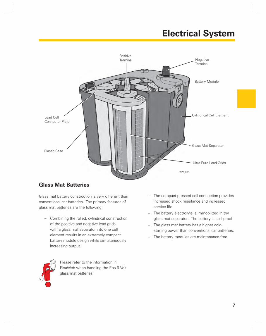
The Convertible Top Sensor System
The Eos has an extensive roof sensor system.
The illustration below shows the approximate location of the individual sensors inside the convertible top. The table on the opposite page shows a breakdown of the tasks and installation locations of the sensors in a summary format. Detailed information can be found in the “Electrical Components“ chapter.
All the sensors are Hall sensors, except for the luggage cover sensor. The Luggage Cover Contact Switch F364 is a microswitch located on the left rear luggage compartment trim. This switch registers when the luggage cover has engaged into the “down” position.
Two types of Hall sensor are used:
Hall sensors with integral reference magnets and
Hall sensors with external reference magnets.
These sensors do not register complete travel, they only measure if a component is in the correct position or not. As a result, the Convertible Top Control Module cannot determine at which intermediate position a roof segment is located at any particular point in time, but only whether it is in one of the end positions.
Most of the sensors are duplicated from one side of the vehicle to the other. This ensures the highest possible operating safety.
–
–
S379_056

Convenience and Comfort Features
21
No Designation Name Task
1 G556 Left Roof Pillar Front Position Sensor
It indicates that the convertible top has docked against the windshield header on the left side of the vehicle.
2 G557 Right Roof Pillar Front Position Sensor
It indicates that the convertible top has docked against the windshield header onto the passenger side of the vehicle.
3 G560 Rear Window Frame Left Lock Sensor
It indicates that the C-segment on the driver side is closed and locked onto the M-segment.
4 G561 Rear Window Frame Right Lock Sensor
It indicates that the C-segment on the passenger’s side is closed and locked to the M-segment.
5 G562 Rear Window Frame Opening Sensor
It indicates that the C-segment is open.
6 G563 Parcel Shelf Left Lock Sensor
It indicates that the trunk lid is released on the left and locked for the “Luggage compartment“ function.
7 G564 Parcel Shelf Right Lock Sensor
It indicates that the trunk lid is released on the right and locked for the “Luggage compartment“ function.
8 G565 Top Stowage Sensor It indicates that the roof assembly is stowed in the luggage compartment in the end position.
9 G566 Left Roof Pillar Opening Sensor
It indicates that the roof pillar fl ap on the driver’s side is open.
10 G558 Left Roof Pillar Lock Sensor
It indicates that the roof side pillar on the driver’s side is locked onto the A-pillar.
11 G559 Right Roof Pillar Lock Sensor
It indicates that the roof side pillar on the passenger’s side is locked onto the A-pillar.
12 G567 Right Roof Pillar Opening Sensor
It indicates that the roof pillar fl ap on the passenger’s side is open.

22
Convenience and Comfort Features
Hall Sensors in the Roof Sensor System
Hall sensors are used for position detection.
In the case of the Eos roof sensor system, three types of Hall sensors are used:
Hall sensors with integral magnet,
Hall sensors with one external magnet,
Hall sensors with two external magnets.
Example of Sensor With Integral Reference Magnet
This design is used for the roof pillar fl ap opening sensors. In these sensors, the signal voltage changes when the roof pillar fl ap carrier moves into the magnetic fi eld of the integral magnet. By positioning the sensor appropriately, it is possible to determine when the component being monitored reaches its end position. However, with this design, the sensor electronics cannot distinguish whether the component being monitored is at the other end position or is between both end positions.
The disadvantage of this design is that the sensor and the component being monitored must be positioned very accurately relative to each other. This assures that the component being monitored can have a strong enough effect on the signal voltage when moving through the magnetic fi eld of the magnet. Strict attention must be paid during repair operations to maintain the clearance between the sensor and the component.
–
–
–
•
Hall Sensor with Integral Magnet
Roof Pillar Flap Ccarrier
Flap Not Open
Flap Open
S379_075
S379_076
Convenience and Comfort Features
23
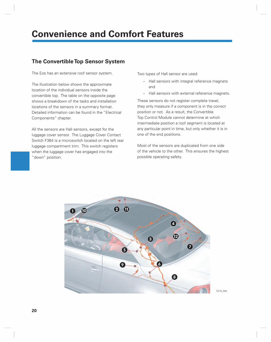
Example of Sensor With One External Reference Magnet
Hall sensors with external magnets allow for larger dimensional tolerances between the sensor and the component being monitored, allowing adjustments with tolerances. One example of Hall sensors with external magnets are the sensors for the locking mechanism of the rear window frame to the M-segment. The locking mechanism for these sensors has the magnet. The Hall sensor uses this magnet to determine the two pieces of information “Locked“ and “Not Locked“.
Example of Sensor With Two External Reference Magnets
Hall sensors with two external magnets are used in order to recognize whether a locking mechanism, such as the one used for the trunk lid, is in one of the end positions or in an intermediate position. Both magnets are positioned on the moveable part so that one of them is over the fi xed sensor when the component to be monitored is in each one of the end positions. This design allows the sensor to distinguish between the locked and unlocked positions. It can also determine that the component being monitored is in an intermediate position.
•
•
External Magnet
Locking Link
Hall Sensor
Link Unlocked
Link Locked
External Magnet 1
Locking Link
Hall Sensor
Link Unlocked
Intermediate Position
Link Locked
External Magnet 2
S379_074
S379_073
S379_070
S379_071
S379_072

24
Convenience and Comfort Features
The Hydraulic Unit
A single hydraulic unit supplies hydraulic fl uid to the 8 hydraulic cylinders of the convertible top and the trunk lid. It is located in the luggage compartment, under the fl oor panel and is enclosed in a foam cover.
Hydraulic Unit Design
The hydraulic unit consists of the Pump Tank, the Electrical Convertible Top Hydraulic Pump V118 and the Valve Unit with three 2-way solenoid valves. The Hydraulic Pump Temperature Sensor G555 is integrated into the pump and monitors the temperature of the hydraulic fl uid to prevent high temperatures.
Pump Tank Valve Unit Convertible Top Hydraulic Pump V118
Hydraulic Connections Foam Enclosure Hydraulic Connections
The Convertible Top Hydraulic Pump V118 is activated by the Convertible Top Control Unit J256. The hydraulic pump operates by rotating in both a clockwise and a counter-clockwise rotation.
All hydraulic connections are marked with a numeric code so that they can be easily identifi ed during assembly.
S379_163
S379_066

Convenience and Comfort Features
25
Valve Unit Design
The valve unit consists of three 2-way solenoid valves, many check valves, a mechanical dual-pressure valve and an emergency shut-off valve. The solenoid valves are:Power Convertible Top Valve 1 N272,Power Convertible Top Valve 2 N341 andPower Convertible Top Valve 3 N342.The emergency shut-off valve opens a by-pass which removes pressure from the system.
When an electrical current is applied to a valve, it lets the pressure fl ow through. If no current is applied, the hydraulic fl uid can fl ow back in opposite direction to the pump tank (return fl ow position). The specifi c valve arrangement and the control of the pump direction of rotation allows the activation of the four pairs of cylinders independently of each other.
The following section describes the individual steps of the entire roof motion during opening and closing.
a Mechanical Check Valveb Mechanical Check Valvec Mechanical Dual-Pressure Valve
Hydraulic Cylinder in the Roof Pillar
Hydraulic Cylinder in the Main Hinge
Hydraulic Cylinder in the Trunk Lid Mounting Bracket
Hydraulic Cylinder in the Trunk Lid Hinge
Illustration with the roof closed
S379_010
N272
N341
N342
V118 J256
1 2 3 4
b
bb
a
c
a

26
Convenience and Comfort Features
Opening the Convertible Top
1. The pump is activated in clockwise rotation. Hydraulic fl uid reaches the solenoid valves through the check valve (a). Current is applied to N272, N341 and N342 and they open. The Valve N342 receives the pressure through the second check valve (b).
Pressure is applied to both connections of each cylinder (3). Since the surface area is larger piston on the bottom off the cylinder than on the top, the cylinder extends. As a result of the hydraulic cylinder movement, the trunk lid locking mechanism on the body and C-segment is released. The mounting bracket is locked to the trunk lid so that the trunk lid can rotate toward the rear in the next step of the roof operation.
2. The pump rotation is inverted, and current continues to be applied to the three valves N272, N341 and N342. In this position, the pump pressure compresses the hydraulic cylinders in the roof pillars (1). As a result, the C-segment is released at the top and rotated over the middle segment. In addition, the roof pillars are released from the A-pillars. The check valve (a) above the hydraulic pump closes against the return fl ow from the roof pillar hydraulic cylinders so that the remaining cylinders are held at their current position.
S379_089
S379_044
S379_059
S379_012
N272
N341
N342
V118
J256
1
a
b
3
N272
N341
N342
V118
J256
a
b
1

Convenience and Comfort Features
27
3. The pump continues to pump counter-clockwise. Valve N342 switches to the return fl ow position. The pump discharge fl ow now reaches the hydraulic cylinders in the trunk lid hinges (4) and moves the pistons into the cylinders. As a result, the trunk lid swings open to the rear and the roof pillar fl aps open. The roof assembly can now be stowed in the luggage compartment. The hydraulic cylinders in the roof pillars continue to remain under pressure and keep the C-segment in position above the M-segment.
4. Valve N272 is switched to the return fl ow position. Current is now applied only to the valve N341 to let the discharge fl ow pass through. With the valves in this position, the hydraulic fl uid from the pump compresses the two hydraulic cylinders in the main hinges (2). The roof assembly is lowered into the luggage compartment, with the roof pillars moved outward by the frame linkage.
S379_044
S379_044
S379_044
S379_044
N272
N341
N342
V118
J256
a
b
4
N272
N341
N342
V118
J256
a
b
2

28
Convenience and Comfort Features
5. Current is now applied to valves N341 and N342 by the Convertible Top Control Module J256. The hydraulic pump discharge direction remains counter-clockwise.
The two hydraulic cylinders in the trunk lid hinges (4) are extended so that the trunk lid and the roof pillar fl aps are now closed.
6. With the pump running counter-clockwise, the valve N342 directs the fl uid to compress the hydraulic cylinders in the trunk mounting brackets (3). As a result, the mounting bracket is locked to the body and released from the trunk lid. The C-segment is locked in the luggage compartment by rubber stops. When the current is removed from valve N342 and the hydraulic pump is switched off by the Convertible Top Control Module, the convertible top movement is complete.
The system is no longer under pressure.
S379_064
S379_014
S379_091
S379_019
N272
N341
N342
V118
J256
a
b
4
N272
N341
N342
V118
J256
a
b
3

Convenience and Comfort Features
29
Closing the Roof
1. The hydraulic pump starts to run counter-clockwise, and current is applied to the valves N341 and N342. The hydraulic cylinders in the trunk lid mounting brackets (3) extend because the working pressure in the space below the pistons is acting on a larger piston area than the pressure in the space above the piston.
The mounting bracket locking mechanisms move into position to open the trunk lid.
2. The pump continues to run counter-clockwise and current is applied only to valve N341. The discharge fl ow reaches the hydraulic cylinders in the trunk lid hinges (4) through the second check valve (b). Since valve N342 is in the return fl ow position, the two cylinders are compressed so that the trunk lid and the roof pillar fl aps open.
S379_046
S379_093
S379_045
S379_092
N272
N341
N342
J256
a
b
3
N272
N341
N342
V118
J256
a
b
4
V118

30
Convenience and Comfort Features
3. Valve N341 switches to the return fl ow position, and valve N272 opens and allows the discharge fl ow to pass through. As a result, the two hydraulic cylinders in the main hinges (2) are extended. The main drive raises the roof assembly out of the luggage compartment. The roof pillars are pulled back inward and dock against the A-pillars.
4. With the pump running counter-clockwise, all three valves open. The discharge fl ow reaches the hydraulic cylinders in the trunk lid hinges (4) and extends them. The trunk lid and the roof pillar fl aps close.
S379_048
S379_094
S379_047
S379_067
N272
N341
N342
V118
J256
a
b
2
N272
N341
N342
V118
J256
a
b
4

Convenience and Comfort Features
31
5. The hydraulic pump motor changes its direction of rotation. The three solenoid valves remain open. The pump discharge fl ow extends the hydraulic cylinders in the roof pillars (1). The C-segment is lowered and locked to the M-segment. Simultaneously, the roof pillars are locked to the A-pillars.
6. With the pump running clockwise, only the valve N342 remains open. The hydraulic cylinders in the trunk lid mounting brackets (3) are compressed. The trunk lid and C-segment locking mechanisms close and secure the roof end position in the “closed“ position. Simultaneously, the trunk lid is released from the internal locks to allow for normal customer opening. The movement of the roof is completed when the hydraulic pump is switched off and current is no longer applied to valves N272, N341 and N342. The system is no longer under pressure.
S379_068
S379_050
S379_095
S379_051
N272
N341
N342
V118
J256
a
b
1
N272
N341
N342
V118
J256
a
b
3

32
Convenience and Comfort Features
The Trunk Lid Assistant
If the Eos is equipped with Park Distance Control (PDC), this feature includes the additional Trunk Lid Assistant function. This is a convenience function and helps avoid damage to the trunk lid when stowing the convertible top.
The Trunk Lid Assistant operates independently of the Park Distance Control and uses the following components to operate:
Park Distance Control sensors in the rear bumper
The convertible top operation sensors
The convertible top operating switch
Chime
The instrument panel insert display
The Park Distance Control is only active when Reverse gear is engaged, while the Trunk Lid Assistant is active as soon as the trunk lid is released to move the top. If Reverse gear is engaged, the Trunk Lid Assistant takes precedence over the Park Distance Control.
–
–
–
–
–
Park Distance Control
Trunk Lid Assistant
Detection Range for the Trunk Lid Assistant
Maximum Horizontal Travel of the Trunk Lid
While the Park Distance Control issues a continuous alarm buzzer in the event of an obstacle about 12 inches behind the vehicle, the Trunk Lid Assistant triggers an alarm for a distance of about 20 inches behind the vehicle. This ensures that enough space is available for the trunk lid travel (about 15 inches).
S379_165
S379_166
Convenience and Comfort Features
33
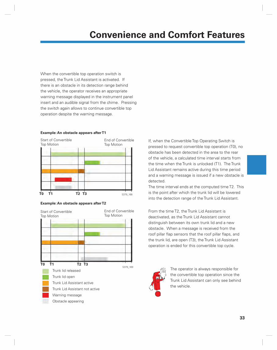
When the convertible top operation switch is pressed, the Trunk Lid Assistant is activated. If there is an obstacle in its detection range behind the vehicle, the operator receives an appropriate warning message displayed in the instrument panel insert and an audible signal from the chime. Pressing the switch again allows to continue convertible top operation despite the warning message.
If, when the Convertible Top Operating Switch is pressed to request convertible top operation (T0), no obstacle has been detected in the area to the rear of the vehicle, a calculated time interval starts from the time when the Trunk is unlocked (T1). The Trunk Lid Assistant remains active during this time period and a warning message is issued if a new obstacle is detected.The time interval ends at the computed time T2. This is the point after which the trunk lid will be lowered into the detection range of the Trunk Lid Assistant.
From the time T2, the Trunk Lid Assistant is deactivated, as the Trunk Lid Assistant cannot distinguish between its own trunk lid and a new obstacle. When a message is received from the roof pillar fl ap sensors that the roof pillar fl aps, and the trunk lid, are open (T3), the Trunk Lid Assistant operation is ended for this convertible top cycle.
Example: An obstacle appears after T1
Trunk lid released
Trunk lid open
Trunk Lid Assistant active
Trunk Lid Assistant not active
Warning message
Obstacle appearing
Start of Convertible Top Motion
End of Convertible Top Motion
Example: An obstacle appears after T2
Start of Convertible Top Motion
End of Convertible Top Motion
The operator is always responsible for the convertible top operation since the Trunk Lid Assistant can only see behind the vehicle.
S379_169
S379_168T0 T1 T2 T3
T0 T1 T2 T3

34
Convenience and Comfort Features
Operating Conditions
In order to perform a convertible top cycle, various conditions must be met. This applies to both opening and closing of the convertible top. One critical element is the knowledge of where each component of the top is located. This applies both to the position of the roof assembly within its own motion sequence (e.g. same signal from a pair of sensors) as well as to the position of the roof assembly within the entire motion sequence for the roof and the trunk lid (e.g. the C-segment must not rotate down before the trunk lid is closed).
Conditions for opening the roof
1. Ignition Terminal 15 is “on”
2 The convertible top position is closed
3. The CAN data bus reports “Communication is possible“
4 The sunroof reports “Communication is possible“
5 The position of the sunroof is recognized
6 The Airbag Control Module reports: “Rollover protection not extended“
7 The microswitch detects convertible top protection latched
8 The Engine Control Module (ECM) (or ABS control module/instrument panel insert) reports “Vehicle speed is less than 1km/h”
9 The Convertible Top Control Module senses a roof movement not yet completed, i.e., the information “Roof open“ is not yet available
10 The sensor system reports “Trunk lid is closed”
11 The convertible top operation switch provides a plausible signal
12 The hydraulic pump temperature sensor reports “Temperature below 203°F (95°C)*
13 The hydraulic unit reports a valve run time lower than 8 minutes **
14 The vehicle electrical system control module reports system voltage higher than 10.8 volts
15 The door control modules report the specifi ed window position

Convenience and Comfort Features
35
* If the temperature of the hydraulic fl uid is above 203°F (95°C), only the command “Close top“ is possible. With a hydraulic fl uid temperature above 221°F (105°C), actuation of the convertible top is completely disabled until the temperature has dropped below the threshold value.
** If the valves in the hydraulic unit are operated for more than 8 minutes, possibly because of repeated opening and closing, the convertible top controls will only allow the top to be closed. It is no longer possible to open the top. This is one of the measures intended to prevent overheating of the hydraulic fl uid.
16 The Lid Closing Assist reports “closed“ after the Comfort System Central Control Module has given the signal “Main latch convertible top compartment cover closed“
17 The Instrument Cluster Control Module reports outside temperature above 5°F ***
18 The heated rear window is Off. It is deactivated automatically when the convertible top switch is actuated
19 The Trunk Lid Assistant, function of the Park Assist (special equipment) reports that the area behind the vehicle has no obstacles
*** If the temperature drops below 5°F, it is assumed that the viscosity of the hydraulic fl uid may be too viscous to permit roof operation.
2 All sensors for a particular movement must provide a correct signal
7 The signal from the microswitch that the luggage cover is in position is not critical for closing the roof
9 The top may not be completely closed for the “Close“ command
12 Hydraulic fl uid temperature of more than 203°F but less than 221°F does not affect the Close command
13 The total actuation time of the hydraulic pump valves must be less than 9.5 minutes for the closing function to be enabled
Conditions for closing the top
The conditions are mostly the same as those for opening, with the exceptions of:

36
Convenience and Comfort Features
Conditions for Terminating the Convertible Top
Movement
In order to prevent damage to the roof, various conditions apply that result in cancelling the convertible top movement. Depending on the condition that occurred to cause cancelation, the convertible top reacts differently. These actions range from stopping convertible top movement if the vehicle top can no longer be opened or closed, to lowering the roof assembly in timed steps if the operation time is exceeded, or to a complete shut down if the operating voltage is lost.
The following conditions result in termination of convertible top operation:
1 The vehicle electrical system voltage drops below 9.0 volts
2 The ignition (terminal 15) is switched off
3 The communication over the CAN data bus is interrupted
4 The Convertible Top Control Module identifi es at least one defective hydraulic valve
5 The Convertible Top Control Module identifi es a defect in the hydraulic unit
6 The sensor system reports that the trunk lid is not closed
7 The sensor system reports that the Lid Closing Assist is not closed
8 The sensor system is providing unlikely signals on the convertible top position
9 The speed detected is above 0.6 mph (1km/h)
10 The hydraulic pump temperature rises above 221°F (105°C)
11 The output stage of the Convertible Top Control Module is overheated (overheating protection)
12 The Convertible Top Control Module fails due to an internal error
13 The door control modules are providing unlikely signals on window position or are reported as failing
14 The Comfort System Central Control Module is providing unlikely signals or no signals
15 The gateway is providing unlikely signals or no signals
16 The Transmission Control Module (TCM) is providing unlikely signals or no signals
17 The Engine Control Module (ECM) is providing unlikely signals or no signals

Convenience and Comfort Features
37
18 The operating time for the hydraulic valves totals more than 9.5 minutes*
19 The rollover bar has been extended
20 Signal from the Convertible Top Operation Switch is interrupted**
21 The Convertible Top Control Module is generating a timeout error***
22 The luggage cover microswitch is reporting during the opening process that the convertible top cover is not latched
23 Outside temperature drops below the threshold of 5°F while the top is being operated
24 The Convertible Top Control Module determines that the temperature sensor in the hydraulic unit has failed
.* If 8 minutes is exceeded, the convertible top operation is terminated.** The switch may be defective or the operator releases the convertible top switch.*** Under certain circumstances, the hydraulic pump runs although some preceding steps of the mechanical
sequence have not yet been performed or completed. The Convertible Top Control Module registers this condition and switches the hydraulic pump off after a few seconds.

38
Convenience and Comfort Features
Roof Controls System
Overview
Sensors
Convertible Top Operation Switch E137
Sunroof Button E325
Central Window Regulator Switch (in driver’s door)
E189
Luggage Cover Contact Switch F364
Hydraulic Pump Temperature Sensor G555
Left Roof Pillar Front Position Sensor G556
Right Roof Pillar Front Position Sensor G557
Left Roof Pillar Lock Sensor G558
Right Roof Pillar Lock Sensor G559
Rear Window Frame Left Lock Sensor G560
Rear Window Frame Right Lock Sensor G561
Rear Window Frame Opening Sensor G562
Parcel Shelf Left Lock Sensor G563
Parcel Shelf Right Lock Sensor G564
Top Stowage Sensor G565
Left Roof Pillar Opening Sensor G566
Right Roof Pillar Opening Sensor G567
Convertible Top
Control Module
J256
CAN Databus
S379_158
Convenience and Comfort Features
39
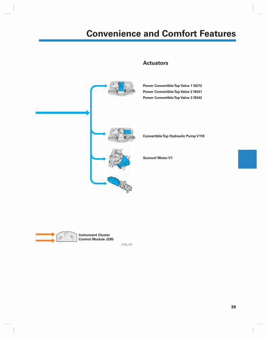
Actuators
Power Convertible Top Valve 1 N272
Power Convertible Top Valve 2 N341
Power Convertible Top Valve 3 N342
Convertible Top Hydraulic Pump V118
Sunroof Motor V1
Instrument Cluster
Control Module J285
S379_159
40
Convenience and Comfort Features
Electrical Components
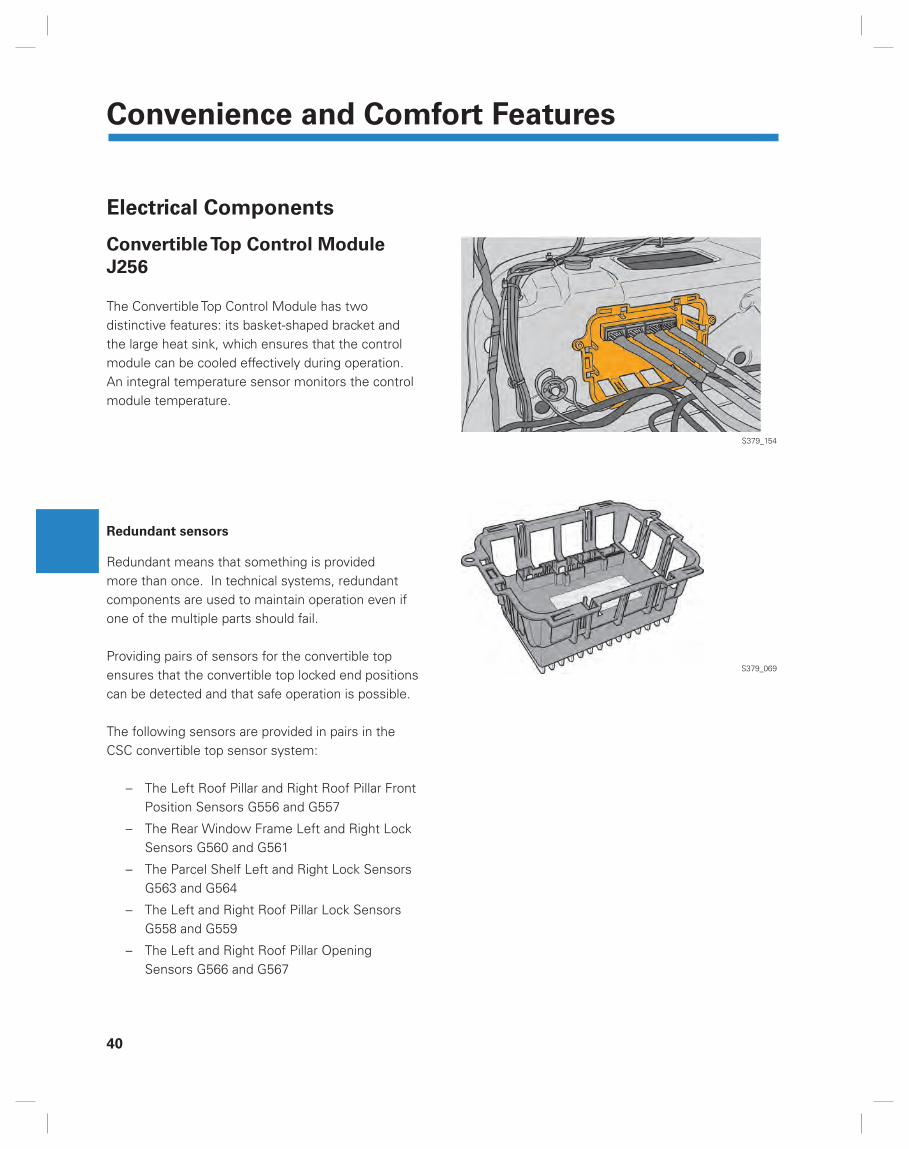
Convertible Top Control Module
J256
The Convertible Top Control Module has two distinctive features: its basket-shaped bracket and the large heat sink, which ensures that the control module can be cooled effectively during operation. An integral temperature sensor monitors the control module temperature.
Redundant sensors
Redundant means that something is provided more than once. In technical systems, redundant components are used to maintain operation even if one of the multiple parts should fail.
Providing pairs of sensors for the convertible top ensures that the convertible top locked end positions can be detected and that safe operation is possible.
The following sensors are provided in pairs in the CSC convertible top sensor system:
The Left Roof Pillar and Right Roof Pillar Front Position Sensors G556 and G557
The Rear Window Frame Left and Right Lock Sensors G560 and G561
The Parcel Shelf Left and Right Lock Sensors G563 and G564
The Left and Right Roof Pillar Lock Sensors G558 and G559
The Left and Right Roof Pillar Opening Sensors G566 and G567
–
–
–
–
–
S379_154
S379_069

Convenience and Comfort Features
41
Electrical Components -
Sensors
Left Roof Pillar Front Position
Sensor G556
Right Roof Pillar Front Position
Sensor G557
Both sensors are Hall sensors with integral reference magnets. They are mounted on the left and right side of the windshield header above the windshield. The electrical connection is made through the A-pillars to the vehicle wiring harness.
Signal use
The sensors indicate that the CSC roof has docked at the windshield header.
Impact of a failure
If one of the two sensors fails (short circuit or open circuit), the reading from the other one is used to monitor whether the CSC roof has docked at the windshield header and is closed. It will not be possible to open the roof again with a failed sensor.
If both sensors fail, it is not possible to operate the top.
Electrical Circuit
S379_118
S379_135
G556 G557
J256

42
Convenience and Comfort Features
Left Roof Pillar Lock Sensor G558
Right Roof Pillar Lock Sensor G559
The sensors are in the front part of the roof pillars, on the locking mechanisms for locking the roof pillars to the A-pillars. They are Hall sensors with integral magnets, and the locking hooks themselves act on the sensor.
Signal Use
The signal from these sensors indicates that the CSC roof is locked to or released from the A-pillars. If the sensor detects that the locking mechanism is open, this means that the roof pillars are free and the roof assembly can be lowered. The signal also indicates that convertible top operation has begun, or that the convertible top is no longer in the “closed“ position.
Impact of a failure
If one of the two sensors fails with the convertible top not closed, the reading from the other one is used to check whether the CSC roof is locked to or released from the A-pillar. The activation time for the hydraulic cylinders in the roof pillars is extended by a fraction of a second after recognizing an acceptable signal from the working sensor.
With only one sensor signal, it is no longer possible to determine that the two roof pillars are correctly locked to or released from the A-pillars. It is still possible to proceed if the roof is at least partially open.
Electrical Circuit
S379_136
S379_149
G558 G559
J256

Convenience and Comfort Features
43
Electrical Circuit
Rear Window Frame Left Lock
Sensor G560
Rear Window Frame Right Lock
Sensor G561
The sensors are located at the C-segment locking hooks in the left and right roof pillar. With two external magnets on the locking hook, they recognize the locking status of the C-segment relative to the roof pillars and the M-segment.
Signal Use
The signal from these sensors indicates that the C-segment is in the “closed“ position and the C-segment is locked to the roof pillars. If the sensor detects that the locking hook is open, this means that the C-segment is free to rotate over the M-segment.
Impact of a failure
If one of the two sensors fails with the convertible top not closed, the reading from the other sensor is used to check whether the C-segment is locked to the roof side pillar. The activation time for the hydraulic cylinders in the roof pillars is extended by a fraction of a second after recognizing an acceptable signal from the working sensor.
With only one sensor signal, it is no longer possible to determine that the C-segment is correctly locked or released on both sides of the vehicle.
It is still possible to proceed with the roof at least partially open.
Locking Hook G560/G561S379_119
S379_137
G560 G561
J256

44
Convenience and Comfort Features
Electrical Circuit
Rear Window Frame Opening
Sensor G562
This Hall sensor with an integral magnet is located in the left roof pillar near the hydraulic cylinder actuating the C-segment.
Signal Use
The signal indicates that the C-segment is in the “open“ position and that the C-segment has completed its movement above the M-segment.
Impact of a failure
Without the sensor signal, the Convertible Top Control Module cannot determine directly whether the hydraulic cylinders have opened the C-segment completely. It only knows from the other sensors that the C-segment is not closed. Without this signal, it cannot be determined that the C-segment has reached its end position above the M-segment. The roof movement will be cancelled..
S379_120
S379_138
G562
G562
J256

Convenience and Comfort Features
45
Electrical Circuit
Parcel Shelf Left Lock Sensor G563
Parcel Shelf Right Lock Sensor
G564
The sensors are located at the hooks locking the trunk lid to the body on the left and right sides of the vehicle. Two external magnets are located on the locking hook. The location of these magnets in relation to G563 and G564 determine the locking status of the components.
Signal use
The signal from these sensors indicates that the trunk lid is in the “locked“ position and is therefore connected to the vehicle body, or is in the “unlocked“ position and can therefore be rotated upward.
If, with the roof closed, the sensor detects that the locking hook is open, this also means that the C-segment is no longer locked to the trunk lid at the bottom. It can rotate over the M-segment.
With the roof closed, the signal additionally indicates that the C-segment is locked onto the trunk lid.
This signal indicates it is possible that the trunk lid is moving in the “open“ direction.
Impact of a failure
If one of the two sensors fails with the convertible top not closed, the reading from the other sensor is used to check whether the trunk lid and the C-segment are in the locked/released position. The activation time for the roof pillar hydraulic cylinders is extended by a fraction of a second after recognizing an acceptable signal from the working sensor.
Locking Hook with Reference Magnets
But with only one sensor signal, it is no longer possible to determine that the trunk lid, and depending on the situation, the C-segment, are latched on both sides.
If the roof is opened, it is only possible to proceed with a closing procedure.
G563/G564
S379_121
S379_139G563 G564
J256

46
Convenience and Comfort Features
Electrical Circuit
Left Roof Pillar Opening Sensor
G566
Right Roof Pillar Opening Sensor
G567
G566 and G567 are Hall sensors with an integral reference magnet. They are on the left- and right-side Roof Pillar Flap Hinges. If a roof pillar fl ap opens, the fl ap mounting bracket moves into the Hall sensor detection area. The signal voltage changes and indicates to the Convertible Top Control Module that the roof pillar fl ap is open.
Signal use
The signal indicates that the trunk lid is opened and that the roof pillar fl aps are in the “Open“ position. The path is cleared for lowering the roof assembly into, or raising the roof assembly from, the luggage compartment.
Impact of a failure
If one of the sensors fails while the roof is not closed, the reading from the other sensor is used to check whether the roof pillar fl ap and the convertible top compartment cover are open or closed. The activation time for the trunk lid mounting brackets hydraulic cylinders is extended by a fraction of a second after detecting an acceptable signal from the working sensor.
With only one sensor signal, it can no longer be determined that both roof pillar fl aps are open or closed. In this case, only the “Close roof“ function is possible. The signals from sensors G563 and G564 serve as a substitute signal indicating “Trunk lid closed“ to the Convertible Top Control Module.
Roof Pillar Flap Hinge
G566/G567
S379_124
S379_125
S379_135
G567 G566
J256

Convenience and Comfort Features
47
Electrical Circuit
Top Stowage Sensor G565
This Hall sensor has an integral reference magnet. It is located on the left main hinge near the hydraulic cylinder for stowing the convertible top.
Signal use
The signal indicates that the roof assembly is in its end position in the luggage compartment, that the convertible top is open, and the trunk lid and the roof pillar fl aps can be closed, or opened, again. When the top is being closed, the sensor signal indicates that roof movement is taking place and the roof assembly has left its position in the luggage compartment.
Impact of a failure
If the sensor fails, the roof movement is halted only with the top completely open or completely closed, since the Convertible Top Control Module cannot be certain that the roof assembly has reached its end position in the luggage compartment.
If the sensor fails with the roof assembly in an intermediate position, the roof assembly is stowed or raised in the intended direction. Then any further top movement is canceled. This would mean that the trunk lid remains in the “Open“ position.
Main Hinge
S379_122
S379_140
S379_123
G565
G565
J256

48
Convenience and Comfort Features
Electrical Circuit
Hydraulic Pump Temperature
Sensor G555
The temperature sensor is integral to the hydraulic pump and cannot be replaced. It measures the hydraulic unit temperature.
Signal use
The temperature signal protects the convertible top system from overheating.
Impact of a failure
If the failure occurs with the top completely opened or completely closed, no further operations are possible. If the failure occurs with the top not completely closed, operation is still possible until the top position “Closed“ has been reached.
The Convertible Top Control Module continues to monitor for exceeding run time (max. 8 min. or max. 9.5 min.).
S379_148
S379_142
G555
J256

Convenience and Comfort Features
49
Electrical Circuit
Luggage Cover Contact Switch
F364
The Contact Switch F364 is located in the left luggage cover mounting bracket. With the exception of the contact switch, the left luggage cover mounting bracket is identical to the right mounting bracket. The switch is designed to be “Normally Closed“. This means that with the luggage cover correctly latched, the control module input is open.
Signal use
The signal indicates that the luggage cover is latched and the roof movement can therefore be enabled.
Impact of a failure
If a failure occurs in the contact switch with the convertible top closed or while the top is moving towards “Open“, the Convertible Top Control Module can no longer determine whether the luggage cover has been installed. Therefore, the movement of the top is either not enabled by the control module, or is canceled.
If the convertible top is completely open, the Luggage Cover Contact Switch signal is of no signifi cance and the top can be closed.
S379_055
S379_054
S379_141
Since the position of this switch is “Open” when the luggage compartment cover is latched, it is important to make sure that this switch is correctly connected to the wiring harness. If the switch is not connected, it will read that the luggage compartment cover is stowed correctly and allow for roof movement.
F364
J256
50
Convenience and Comfort Features
Electrical Circuit
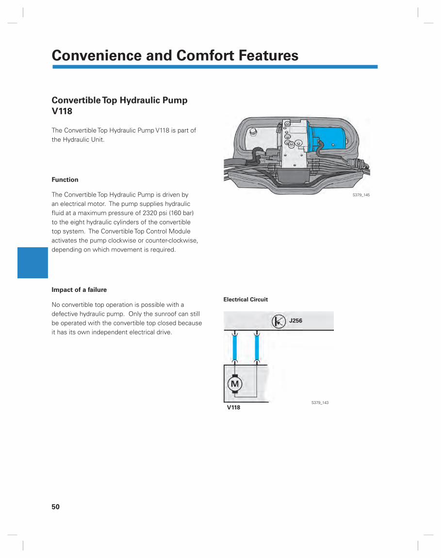
Convertible Top Hydraulic Pump
V118
The Convertible Top Hydraulic Pump V118 is part of the Hydraulic Unit.
Function
The Convertible Top Hydraulic Pump is driven by an electrical motor. The pump supplies hydraulic fl uid at a maximum pressure of 2320 psi (160 bar) to the eight hydraulic cylinders of the convertible top system. The Convertible Top Control Module activates the pump clockwise or counter-clockwise, depending on which movement is required.
Impact of a failure
No convertible top operation is possible with a defective hydraulic pump. Only the sunroof can still be operated with the convertible top closed because it has its own independent electrical drive.
S379_145
S379_143V118
J256

Convenience and Comfort Features
51
Electrical Circuit
Power Convertible Top Valve 1 N272
Power Convertible Top Valve N341
Power Convertible Top Valve N342
All three valves are located in the hydraulic unit valve body.
Function
With the three power convertible top valves, the Convertible Top Control Module operates the eight hydraulic cylinders of the convertible top mechanism.
When no current is applied, the hydraulic fl uid can return to the pump tank. When a valve is activated, it allows the pump discharge fl ow to pass through.
Impact of a failure
If the Convertible Top Control Module identifi es that one or more valves are defective, convertible top operation is suspended and the failure is saved in the Convertible Top Control Module error code memory. Like the pump, the valves and the Hydraulic Pump Temperature Sensor G555 are protected against overheating by the Convertible Top Control Module computing the correct running time.
Valve Without Current Applied
Valve With Current Applied
Return Discharge Flow
S379_147
S379_161
S379_144
If the top is left in an intermediate position with the ignition in the ONN position while performing work, the computed time keeps running. This can cause the top to stop operating due to temperature protection.
J256
N272 N341 N342
J256

52
Convenience and Comfort Features
Operating Diagram
Diagnostic
Connector
Comfort System CAN Data Bus
Powertrain
CAN Data Bus
Instrument Panel CAN Data Bus
E137 Convertible Top Operation SwitchE325 Sunroof ButtonE189 Central Window Regulator Switch (in driver’s door)E256 ASR/ESP ButtonF364 Luggage Cover Contact SwitchJ256 Convertible Top Control ModuleJ285 Instrument Cluster Control ModuleJ386 Driver’s Door Control ModuleJ387 Front Passenger’s Door Control Module
J388 Left Rear Door Control Module J389 Right Rear Door Control Module J533 Data Bus On Board Diagnostic InterfaceJ567 Door Closing Assist Control ModuleL76 Push Button IlluminationS FusesV329 Closing Assist Motor
S379_133
N272
SS J386 J387 J388 J389
J526
L76
J657 V329
J519
E256 E137 F364
J386
L76

Convenience and Comfort Features
53
Input SignalOutput SignalPlusGroundCAN Data-bus
G555 Hydraulic Pump Temperature SensorG556 Left Roof Pillar Front Position SensorG557 Right Roof Pillar Front Position SensorG558 Left Roof Pillar Lock SensorG559 Right Roof Pillar Lock SensorG560 Rear Window Frame Left Lock SensorG561 Rear Window Frame Right Lock SensorG562 Rear Window Frame Opening SensorG563 Parcel Shelf Left Lock Sensor
G564 Parcel Shelf Right Lock SensorG565 Top Stowage SensorG566 Left Roof Pillar Opening SensorG567 Right Roof Pillar Opening SensorN272 Power Convertible Top Valve 1N341 Power Convertible Top Valve 2 N342 Power Convertible Top Valve 3 V118 Convertible Top Hydraulic Pump
IN OUT
J285
V118 G555 N272 N341 N342
J245
G557G556
J256
G560 G562 G565 G558 G561 G559 G566 G567 G563 G564

54
Convenience and Comfort Features
The Power Easy-Entry Function
The Easy-Entry Function, is an extension of the power seat controls.
Construction
The seat with power Easy-Entry Function has a rocker switch that can be operated to move quickly the seat back and forth. The front part of the switch moves the seat forward, the rear part of the switch moves the seat back. The purpose of this function is to allow easy access to the rear seat.
Operation
Pressing the switch moves the seat forward in Fast Forward (2.5 times faster than with normal fore-and-aft adjustment). The previous seat position is retained in the relevant Entry Assist Control Module. Pressing the rear part of the switch moves the seat in Fast Return to its original position. The fast motion operates independently of the seat back position.
In order to protect people sitting in the front seats, the power Easy-Entry Function operates only
with the vehicle stationary
with the doors open
The function will no longer operate if the doors have been left open for more than 10 minutes.
–
–
Easy-Entry Fast Forward Easy-Entry Fast Return
Tilting the seat back forward manually
Fast Forward with power Easy-Entry Function
S379_156
S379_157
S379_097
S379_098
Radio and Navigation
55
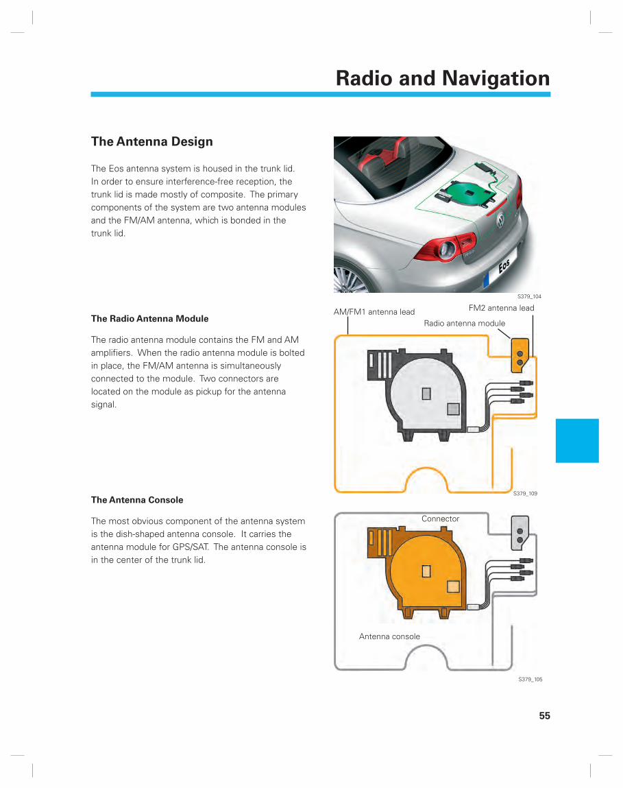
The Antenna Design
The Eos antenna system is housed in the trunk lid. In order to ensure interference-free reception, the trunk lid is made mostly of composite. The primary components of the system are two antenna modules and the FM/AM antenna, which is bonded in the trunk lid.
The Radio Antenna Module
The radio antenna module contains the FM and AM amplifi ers. When the radio antenna module is bolted in place, the FM/AM antenna is simultaneously connected to the module. Two connectors are located on the module as pickup for the antenna signal.
The Antenna Console
The most obvious component of the antenna system is the dish-shaped antenna console. It carries the antenna module for GPS/SAT. The antenna console is in the center of the trunk lid.
AM/FM1 antenna lead FM2 antenna lead
Radio antenna module
Connector
Antenna console
S379_104
S379_109
S379_105

56
Radio and Navigation
The GPS Antenna Module
The GPS module, which also contains the antenna, is housed on the dish-shaped antenna console. The module is connected by a separate wire and connector.
The SAT Antenna Module*
SAT means satellite radio.The antenna is formed by a large copper fi lm applied to the antenna console. The contact to the antenna module is created directly when the module is assembled to the fi lm.
GPS antenna module
SAT antenna module
SAT antenna
* North America only S379_106
S379_107

Service
57
Closing Force Restriction
The sequence of movements when opening and closing the convertible top is extremely complex. Depending on the position of the top, different leverage forces occur on the convertible top components. Because of these different leverage forces, the convertible top controls do not have any closing force restriction. This means that there is a risk of injury if individuals become involved in the movement of the roof as the result of incorrect handling of the convertible top controls.Only the sunroof has its own force limiter for the sunroof operation because of its separate electrical motor.
Please refer to and strictly follow the current instructions in ELSA when performing all repair, assembly or adjustment procedures. Work incorrectly performed can damage the complicated convertible top mechanism and the sensitive controls.

58
Notes

Knowledge Assessment
59
Knowledge Assessment
An on-line Knowledge Assessment (exam) is available for this Self-Study Program.
The Knowledge Assessment may or may not be required for Certifi cation.
You can fi nd this Knowledge Assessment at:
www.vwwebsource.com
For Assistance, please call:
Volkswagen Academy
Certifi cation Program Headquarters
1 – 877 – VW – CERT – 5
(1 – 877 – 892 – 3785)
(8:00 a.m. to 8:00 p.m. EST)
Or, E-Mail:

Volkswagen of America, Inc.3800 Hamlin RoadAuburn Hills, MI 48326Printed in the U.S.A.June 2006