SPE-143570-MS-P Smart EOR Screening, Breaching the Gap Between Analytical and Numerical Evaluations
EOR Screening and Optimizing Study on Carbonate Reservoirs
by
Nor Suzairin Binti Mistor
Dissertation submitted in partial fulfilment of
the requirements for the
Bachelor ofEngineering (Hons)
(Petroleum Engineering)
MAY2011
Universiti Teknologi PETRONAS Bandar Seri Iskandar 31750 Tronoh Perak Darul Ridzuan
CERTIFICATION OF APPROVAL
EOR Screening and Optimizing Study on Carbonate Reservoirs
by
Nor Suzairin Binti Mistor
A project dissertation submitted to the
Geoscience & Petroleum Engineering Programme
Universiti Teknologi PETRONAS
in partial fulfilment of the requirement for the
BACHELOR OF ENGINEERING (Hons)
(PETROLEUM ENGINEERING)
UNIVERSITI TEKNOLOGI PETRONAS
TRONOH, PERAK
MAY2011

~----------- ~-~-~-~~---~~-----~~------------
EOR SCREENING AND OPTIMIZING STUDY ON CARBONATE RESERVOIRS
CERTIFICATION OF ORIGINALITY
This is to certifY that I am responsible for the work submitted in this project, that the original
work is my own except as specified in the references and acknowledgements, and that the
original work contained herein have not been undertaken or done by unspecified sources or
persons.
NOR SUZAIRIN BINTI MISTOR
FINAL REPORT FYP II
EOR SCREENING AND OPTIMIZING STUDY ON CARBONATE RESERVOIRS
ACKNOWLEDGEMENT
I would like to take this opportunity to thank all parties involved in making this project a
great success. Honorably thanking Universiti Teknologi Petronas (UTP) especially my
supervisor, Mr Ali Fikret for giving me this chance to le.am and make t!ae research on this
topic which is EOR Screening and Optimizing Study on Carbonate Reservoirs.
Heartfelt appreciation goes to all the lecturers and UTP staff, which have spend time to
provide additional support and advice throughout the research. Last but not least to all my
fellow friends and my family who have been giving me courage and advice throughout this
course in order to complete my Final Year Project 2(FYP).
FINAL REPORT FYP II
EOR SCREENING AND OPTIMIZING STUDY ON CARBONATE RESERVOIRS
ABSTRACT
By times, production of oil will decrease eventually. Not all the oil in the reservoirs
will be produced during the process. A substantial amount of oil will remain in place
or is called as residual oil saturation (Sor) due to a partial sweep of the reservoir and
oil is trapping by capillary forces in the invaded zones. Therefore, researches have
been developed and Enhanced Oil Recovery (EOR) is the trusted technology to
improve the production and recovery in the oil fields. The objectives ofEOR are (1) to
improve the sweep efficiency, by reducing the mobility ratio between injected and in
placed fluids, (2) to eliminate or reduce the capillary forces and thus improve
displacement efficiency, and (3) to act on both phenomena simultaneously.
Different fields acquire different methods of EOR. Hence, in order to fmd the best
method, a screening process has been done. The criteria and properties of both
method and reservoirs are taken into account in order to choose the exact method for
the specific reservoir. The properties are based on the successful field projects and
continuous research. In this project, which is focusing on the carbonate reservoirs
lithology,all the EOR methods and fields properties will be screened by using two
methods which are (1) manual screening and (2) by using EOR screening. EOR
screening is software that has been developed by the author using the macro visual
basic in Microsoft Excel2007. About 48 previous projects in carbonate reservoirs'
field has been tested using this software and the result shows gas injection as the
mostly suitable method for this lithology.

~------------ --------------------------------EOR SCREENING AND OPTIMIZING STUDY ON CARBONATE RESERVOIRS
TABLE OF CONTENTS
FIGURES ......... ................................................................................................... 6
TABLES ............................................................................................................ 6
ABBREVIATION AND NOMENCLATURE .......................................................... ?
1.0 INTRODUCTION ...................................................... .......................... 8
1.1 Project Background .......................................................................................... 8
1.2 Problem Statement. .......................................................................................... 9
1.2.1 Problem Identification .............................................................................. 9
1.2.2 Significant of the Project. ........................................................................ 1 0
1.3 Objective .................................................................................................... .! 0
1 .4 Scope of Study .............................................................................................. 11
1.5 Relevancy of the Project ................................................................................. 11
1.6 Feasibility of the Project.. ................................................................................. 11
2.0 LITERATURE REVIEW ............................................................ ........... 12
2.1 Introduction ...................................................................................... 12
2.2 Enhanced Oil Recovery ........................................................................ l2
2.3 EOR Screening .................................................................................. 12
2.4 Carbonate Reservoirs .................................................................................................. 14
2.5 Thermal Method ................................................................................ .14
2.6 Non-Thermal Method ......................................................................... .15
2.6.1 Chemical Flooding .......................................................................... 15
4

EOR SCREENING AND OPTIMIZING STUDY ON CARBONATE RESERVOIRS
2.6.1.1 Polymer Flooding ......................................................................... 16
2.6.1.2 Surfactant-Polymer Flooding (SP) ..................................................... .17
2.6.1.3 Alkali-Surfactant-Polymer Flooding (ASP) .......................................... .17
2.6.2 Gas Flooding ................................................................................ .18
2.6.2.1 N2 Flooding .......................................................................... 18
2.6.2.2 C02 Flooding ........................................................................ 19
2.6.2.3 Applications of gas Injection ...................................................... 19
2.7 Conclusion ........................................................................................... 21
3.0 METHODOLOGY ............................................................................. ... 22
4.0 RESULT AND DISCUSSION .............................. ...................................... 29
5.0 CONCLUSION AND RECOMMENDATION ..................................... ......... .36
REFERENCES
5

-------------- -----------EOR SCREENING AND OPTIMIZING STUDY ON CARBONATE RESERVOIRS
LIST OF TABLES
Table 1: Summary of Screening Criteria for EOR Methods ................................................. l3
Table 2: Screening Criteria .................................................................................................... 24
Table 3: Gantt chart ............................................................................................................... 28
Table 4: Calcium carbonates reservoirs ................................................................................ 29
Table 5: Dolomite reservoirs ................................................................................................. 31
Table 6: Limestone reservoirs ............................................................................................... 32
Table 7: Limestone/Dolomite reservoirs ............................................................................... 34
LIST OF FIGURES
Figure 1: Evolution ofEORprojects by chemical methods in US ....................................... 15
Figure 2: Polymer injection diagram .................................................................................... 16
Figure 3: Gas flooding diagram ............................................................................................ 18
Figure 4: Methodology .......................................................................................................... 22
Figure 5: Database of screening criteria ............................................................................... 25
Figure 6: VBA Coding .......................................................................................................... 26
Figure 7: User input.. ............................................................................................................ 26
Figure 8: User input and result .............................................................................................. 27
Figure 9: Vacuum, New Mexico (San Andres) .................................................................... 27
Figure 10: Percentage methods for dolomite ........................................................................ 28
Figure 11: Percentage methods for calcium carbonates ....................................................... 30
Figure 12: Percentage methods for dolomite ....................................................................... 30
Figure 13: Percentage methods for limestone ..................................................................... .33
Figure 14: Percentage methods for limestone/dolomite ....................................................... 34
6
----------- -------------------------------EOR SCREENING AND OPTIMIZING STUDY ON CARBONATE RESERVOIRS
ABBREVIATION AND NOMENCLATURE
ASP: i\lkaline-Surfactant-Polymer
EOR: Enhanced Oil Recovery
FA WAG: Foam Assisted Water Alternating gas
HPAI: High Pressure Air Injection
1FT: Interfacial tension
M: Mobility ratio
MMP: Minimum Miscibility Pressure
Nc : Capillary number
SWAG: Simultaneous Water and Gas Injection
SP : Surfactant-Polymer
Swi: Initial Water Saturation
Sor: Residual Oil Saturation
WAG: Water alternating gas
7
------------~ -------- -----------------------~ EOR SCREENING AND OPTIMiZING STUDY ON CARBONATE RESERVOIRS
CHAPTER I
lNTRODUCTION
1.1 Project Background
Reservoirs firstly producing oil using natural reservoir energy until a certain stage of
depletion reached and production rates become uneconomic. This is known as
primary production phase. Recoveries by secondary methods such as water or gas
injection are implemented when the natural recovery processes are insufficient.
Tertiary recovery comes afterwards. The term secondary and tertiary recovery or
Enhanced Oil Recovery (EOR) describes the order of which methods are used. EOR
also can be described as the recovery methods by other than natural production.
Declining in oil discoveries years ago make the researcher from oil and gas industry
to find the way to meet the energy demand in years to come and as the result, EOR
technologies is proven as the key for the recovery to continue (Vladimir and Eduardo,
2010). EOR can be divided into two major types of techniques which are thermal and
non-thermal recovery. For thermal, it consists of steam injection, hot waterflooding
and in situ combustion. While for non-thermal recovery, it can be divided into three
(3) types which are chemical flood, waterflood and gas drive (Duraya, 2007).
Worldly known carbonates reservoirs have very complex characteristics. It has
heterogeneities of porosity and permeability. Therefore, the choosing of suitable EOR
methods for this kind of lithology is very difficult. There is evident where gas and
water-based recovery methods are applicable for carbonate reservoirs (E. Manrique et
al., 2010). WAG is the common interest EOR in carbonate reservoirs. Based on E.
Marrrique eta!. (2004), polymer flooding is the only proven EOR chemical of EOR
methods in carbonate formation. A thermal method is not suitable in carbonate
reservoirs because the structured of carbonate reservoirs which highly fractured can
cause early breakthrough of the steam. So the use of thermal methods in not popular
in carbonate reservoirs.
8
~~~~~~~~~~~- -------------------~~~~~~~~~~~-
EOR SCREENING AND OPTIMiZING STUDY ON CARBONATE RESERVOIRS
In order to find the best method of EOR for carbonate reservoirs, a set of screening
test has been developed (David and Michael, 1981) and also the set of screening
criteria based on the primary and thousands of field projects have been recorded (J.J
Taber et al, 1996). The screening process will be conducted using two methods which
are (1) manual screening based on the screening criteria and (2) a screening
programming. Before the screening test take place, all the screening criteria data
should be take into account. The screening criteria are based on the oil properties and
reservoir characteristics (J.J Taber el a!, 1996).
1.2 Problem Statement
1.2.1 Problem Identification
Carbonate reservmrs contributes almost half in oil reserves and many of these
reservoirs are naturally fractured (Roehl and Choqueete, 1985). Carbonates rock
texture has spatial variations in permeability and capillary bound water volumes. It
also has different types of porosity and variations of permeability which make this
lithology has heterogeneity manner.
Fractured carbonate reservoirs which has high porosity but low permeability (Allan
and Sun, 2003) could use EOR processes to optimize the oil production. The oil
recovery from this type of reservoir is very low by conventional waterflooding and
because it is fractured about 80% being originally less water-wet (Yongfu et a/.,
2006).
Complex characteristics of carbonates reservoirs produce complex interrelationships
between porosity, permeability, Swi, Sor, wettability, and capillarity. When pursuing
the EOR processes, the injected fluids will likely flow through the fractured network
and bypass the oil in rock matrix. Therefore, the choosing of EOR processes in this
lithology is also complex and difficult since the understanding of reservoir behaviour
when certain EOR process is conducted is very important in order to choose which
EOR process can provide high production in carbonate reservoirs.
9

-------------------------------------------EOR SCREENING AND OPTIMIZING STUDY ON CARBONATE RESERVOIRS
Based on J.J Taber et al. (1996), screening test using all the screening criteria on oil
properties and reservoir characteristics can help to choose the best EOR method for
carbonate reservoirs.
Initially, this project was proposed to use PRize ™ software, the renowned EOR
screening software in the oil and gas industry. But since the software cannot be run in
UTP, the author needs to create a program almost similar to PRize ™ in order to
make the screening easier. Therefore, two ways to do the screening in this project
which are (1) manual screening based on the screening criteria and (2) a screening
progranuning. The screening program is developed using the Excel VBA Code and
Excel Macro. The properties in this program are based on the PRize™ manual's
screening criteria.
There is only technical screening provided in this project, economic screening on the
specific method might as well be done if the further study is continued.
1.2.2 Significant ofthe Project
This project is very important in order to find the best EOR method for carbonate
reservoir. In this project, suitable EOR method is chosen using (1) manual screening
based on the screening criteria and (2) a screening programming which evaluating and
screening all the properties of the reservoirs. Screening criteria on the reservoir data
should be taken into account to conduct the screening. The criteria are based on oil
displacement mechanisms and the result ofEOR field projects (J.J Taber et al., 1996).
Further study in this topic will help in improving the EOR technique for carbonate
reservoir and also choosing the best method economically.
1.2 Objectives
The ultimate objective of this project is to screen the criteria of carbonate oil
reservoirs and EOR processes using (I) manual screening based on the screening
criteria and (2) a screening programming in order to choose the best EOR process for
that lithology.
10
------------- ---------------------------------EOR SCREENING AND OPTIMIZING STUDY ON CARBONATE RESERVOIRS
The other objective that has been recognized in this project is the optimizing study on
carbonate reservoirs and EOR processes to choose the satisfying EOR process this
lithology.
1.3 Scope of Study
For this project, the scope of study covered about the all the types ofEOR processes
and its criteria. There are two types of EOR processes which are non-thermal and
thermal methods. The suitability of each kind of this EOR processes should be studied
to fmd the best solution for carbonate reservoirs.
The reservoirs characteristic which is carbonate reservoirs also should be taken into
account for this project. In addition, an extensive research on both context which are
EOR methods and carbonate oil reservoirs are very important to make sure
there is no bad effect happen during the EOR processes taking place in that lithology.
The report on the EOR field projects for carbonate reservoirs also can give the
overview on the trend of common EOR process in carbonates reservoirs.
1.4 The Relevancy of the Project
This project is definitely relevance in order to choose and consider all the EOR
methods that are suitable for carbonate reservoirs before further experiment is
conducted and pilot project is implemented. Mter considering the methods by the
screening criteria, the suitable methods will be experimental in order to make sure
the ability ofthe process to the carbonate reservoirs. From that, the production of
oil in carbonate reservoir will be increasing.
1.5 Feasibility ofthe Project
This project is feasible to be implemented and study since the time given is
definitely enough and the tool to conduct the project is available. The time given
to make the raw screening process is satisfying but to do more analysis on the
reservoirs need much more time.
11

PNAL R~POR.T FYP q ~-~-~--~-------~ ~~~-~~~~~~~~-
EOR SCREENING AND OPTIMIZING STUDY ON CARBONATE RESERVOIRS
2.1 Introduction
CHAPTER2
LITERATURE REVIEW
Declining in oil production making the oil companies and authorities sought -after the
new technologies to overcome this problem. Enhanced Oil Recovery (EOR)
technology widely use nowadays in increasing the economic value of existing oil
fields by increased oil recovery and extending the field life (E.Manrique and
J. Wright, 2005)
2.2 Enhanced Oil Recovery
Enhanced Oil Recovery (EOR) technology is trusted by oil companies and authorities
can help to play the key role to meet energy demand for years to come. There are
several EOR methods that has been recognized can help to improve and increase oil
recovery. Based on Sarma (1999), EOR methods are divided by two categories
which are non-thermal and thermal. Non-them1al methods consist of chemical flood,
waterflood, and gas drives while thermal methods consist of steam injection, hot
waterflood, and in-situ combustion.
2.3 EOR Screening
EOR screening is the test required to find the best EOR method for carbonate
reservoirs. Each EOR methods have their own criteria. The criteria are based on the
oil properties and reservoir characteristics. These criteria are called as screening
criteria for EOR methods. The criteria for oil properties are gravity (0 API), viscosity
( cp ), and composition while the reservoir characteristics are formation type, net
thickness (ft), average permeability (md), depth (ft), and temperature (°F) (J.J Taber
et al, 1996). All this data should take into account in order to do the EOR screening.
By doing the screening, the exact method is suitable for carbonate reservoirs can be
deteffilined.
12

F!NA'- '\EPOqT l'YP 'I
EOR SCREENING AND OPTIMIZING STUDY ON CARBONATE RESERVOIRS
In order to do the screening, two ways are develop which are (1) manual screening
based on the screening criteria and (2) a screening progranuning. The screening
program is using Excel VBA Code and Excel Macro. The properties in this program
are based on the PRize.IM manual and screening criteria by J.J Taber et al., (1997).
TABLE 3-SUMMARY OF SCREENING CRITERIA FOR EOR METHODS (j~ ReseoorCh~ics
Detsll m NEl AvBrage Tai>le
" EOR ~ ~""""" Saturatial Fmrra!icrl Thi:lo.nese Perrre;biiy IJepO Temperatme
Ref. t6 - !'API! {q~i C~03ful t~~PVt 1)]1' (ft} (mG1 (ft) I'F,l
"" q.;;,n M<tods (Mi>:i>o)
I Nilrt<l61 illll :-3S.~§.! .-;0.4'.~'· H9lpot<01 :>.to!/:.• -.. r,.,;,m, NC .~s.coo NC lhligas orc1 roc! ill diwi'9
"'"""• 2 Hyrl!t<:alboo :-23..:':!!/ -:3··£1··1 H9Jpom .-.Jill~/ Sane5t·~ Tr.il~ NC c•4,00C tlC
of~WC; ·> diwi'9 cartrnate
3 co, :.2VlS/~ d\!'.1.5'. H9Jpocem .:-20-'SS .• Sanliitv~ \'flOOr~ NC c•1.500' NC - - ofC~ :o C17. -" -...
l-3 lm'II!S~;i:.IF.- c-12 .o:€1:'0 w.; :-3S_i/C ~ NC NCrr~ NC :.1,8()1J NC -gases .and/or goOO veric;]
"''"""'ley (EnhanOldi W.>fioodilg
4 Mioe!S!. :>20-"~.' d;·~1J. L!gr~ ;.3)}~.· Sarnislr?li.' NC .~10/<f.SO.• ,9,001! •11§£ ,2(>)',8C
?0\ffie!, inl~, ""'""" ASP, and SOOleOfgar'.iG Alkaine acit f:lr FlcOOO~ alkaile fkOOs
5 Pcljmof :>15 ..:15(b10 llC :-50/80/ Salaslcfle NC .:>'G/800! t d,OOC :-200··.140 Flwif't1 prek>rred
Th-IJ«hinic~
' CoomusW-"'1 :>10.'16-·? ..:5,0CO """ :>stl.;.z!; ~)fOSity ,.;c ;.:f.!' -:11,500··~3,500 ,,;oc •ill ; "!'haiti: ..,~
1.100 ""'""""" sam'5tme
7 Stam :.BID ill-... ? .::2l'l.IY.li NC :-4!Pffi.• fli9hilorositl ,.10 .~2CIJ/2,:40/~ <4.500 .1.500 llC
4.ioo ..oo·
sand~~
- Surfarerrin~ 7tDI~ Zero llC ,S·.,C; Mneab1e .~Jcf NC ).3:1 NC roH~ow ;a}j ;arsanc O'F.Iblrden t.J
sand raOO
NC-nc:~criti!:al. llnl):rfne.d va!ues r.wr.?SirrllhE approQr.ale mw~ or average fvr current field prujects.
i!.SeeTat!e3ol~ll6. b:-3md fr<m sc"!le ~arbo'E.II? ~eSEM~TI i '* iment is tu swwp c?~~ the fra.:ture S¥5!M'•. '1 rar•m"'llhliy , 2ilfOO.Iicp 'T.-.. olt; ,!iJ md-lt:p eSee depfl.
Table 1: Summary of Screening Criteria for EOR Methods (J.J Taber et al., 1997)
13
--------------------EOR SCREENING AND OPTIMIZING STUDY ON CARBONATE RESERVOIRS
2.4 Carbonate Reservoirs
For this project, it is focusing on the EOR method for carbonate reservoirs.
Carbonates are divided into reefs, clastic limestone, and dolomite. The reservoirs in
this lithology will trap in that formation. Not all EOR methods are suitable for
carbonate reservoirs since carbonate reservoirs has heterogeneous porosity and
permeability. It is also highly fractured and oil-wet type reservoirs. As the carbonate
reservoirs fractured, during the EOR process, the injected tluids will likely tlow
through the fracture network and bypass the oil in the rock matrix. The high
permeability in fracture network and the low porous volume will result in early
breakthrough of the injected tluid. It shows that it is very difficult to pursue EOR
techniques in this kind of lithology. Therefore, deeply study and test is needed to
find the best EOR method for this lithology.
2.5 Thermal Method
Thermal method is generally preferred for shallow oil reservoirs containing viscous
crude oil. The heat will reduce the viscosity of oil and mobilization will be easier. But
for this project, since it is focusing on light oil reservoirs, thermal method will be not
preferable in this project. This method is not popular in carbonate reservoirs because
the fractured carbonate reservoirs will cause the uneven sweeping and irregular steam
can lead to early breakthrough of steam, resulting in low recovery factor (Vladimir
and Eduardo, 2010).
Air Injection or High Pressure Air injection (HP AI) shows an effective recovery
method in deep light crude oil reservoirs (E. Manrique, 2004 ). Air injection is
considered when there is no access to C02 sources at onshore or offshore reservoirs.
HP AI or air injection is not preferable because there will be some addi tiona! cost
elements for air injection process and also some significant risk and uncertainty might
be occurring during the process (T.B Jensen et al., 2000). The other advantages for
air injection are well corrosion, oil oxidisation, and risk of explosion (Marcel Latil,
1980).
14
FINAL REPORT FYP II
EOR SCREENING AND OPTIMIZING STUDY ON CARBONATE RESERVOIRS
2.6 Non-Thermal Method
Non-thermal method consists of chemical flooding, waterflooding, and gas flooding
(After Sarna, 1999). Waterflooding is the process when injection water pushes the oil
towards the producing well. Chemical flooding is a process to increase the mobility of
oil in order to enhance oil recovery. Additives or chemicals are added in displacing
tluid or to the residual oil to control viscosity and interfacial tension. While gas
flooding is divided into immiscible and miscible gas injection. In miscible gas
injection, gas is injected at or above MMP for the gas to miscible in the oil whereas in
immiscible gac; injection, the process is below MMP. Chemical flooding and gas
injection are processes to be considered in carbonate reservoirs.
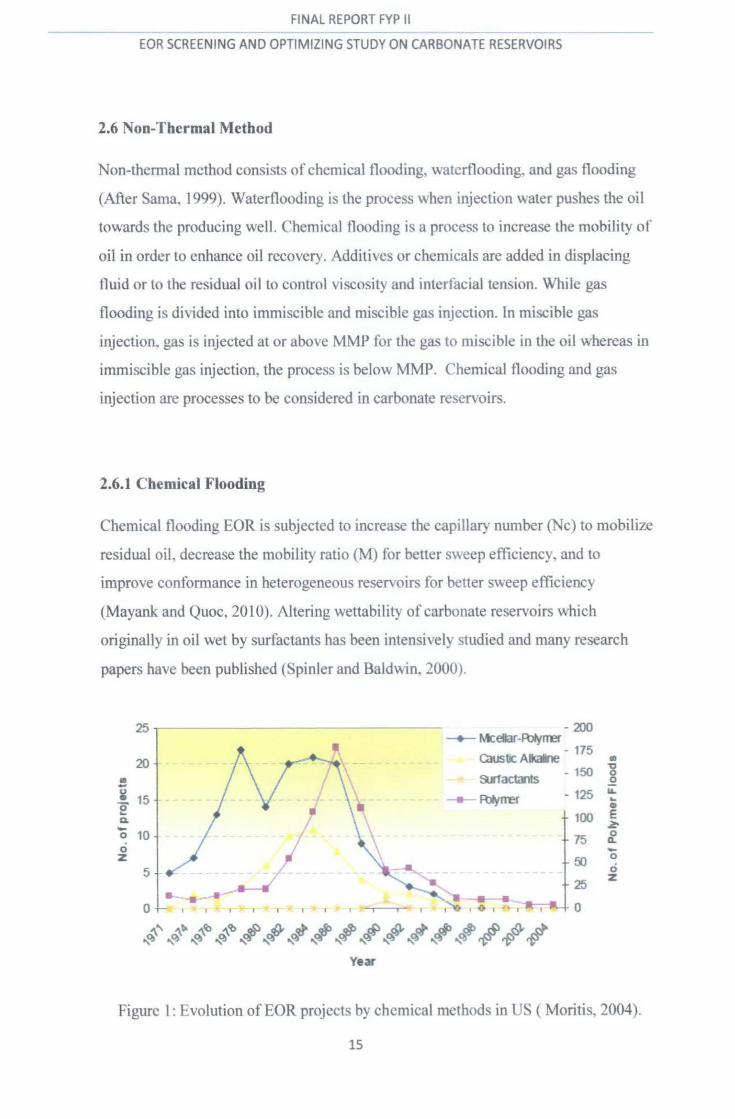
2.6.1 Chemical Flooding
Chemical flooding EOR is subjected to increase the capillary number (Nc) to mobilize
residual oiL decrease the mobil it) ratio (M) for better sweep efficienc}. and to
improve conformance in heterogeneous reservoirs for better sweep efficiency
(Mayank and Quoc, 201 0). Altering wettability of carbonate reservoirs which
originally in oil wet by surfactants has been intensively studied and many research
papers have been published (Spinier and Baldwin. 2000).
25r-----------------------~--------~------
20
~
¥ 15 0 ... Q. -0 10 0 z
5
0
--I'
Year
-200 ~ Mcetar-R»jrrer
. GrustJc Alk<*le - 175 • '1:)
s.tactants - 150 0 ..2
- 125 ~
--- Rllyrrer ... •
100 E ~
75 0 Q.. -50 0
0 25
z
0
Figure 1: Evolution ofEOR projects by chemical methods in US ( Moritis. 2004).
15

FINAL REPORT FYP II
EOR SCREENING AND OPTIMIZING STUDY ON CARBONATE RESERVOIRS
Based on the report above. polymer flooding is the most tmportant chemical method
of EOR. More than 290 polymers field projects have been reported in the literature.
Nevertheless. pol) mer flooding shov.!:i its ability as the proven EOR techno log) in
carbonate light oi I reservoirs.
2.6.1.1 Polymer Flooding
CHEMICAL FLOODING (Polymer)
T,. • !hxl thllo.l oH,Iolllut. , , prof •I k CXnl:IO'l "' (V",l'ri;Oif lhroo I ~JQr" o! a JY.> •'""" rd lUll I.J! rJWtl~ .X,I !r(..IIO rn HI IV • t. Utd IIJ o 'd n Jrv lJ ,_lft1 (\Y:t'i'r 'll m">,l'
• .., wly11 10 t.J uhV' o o.t:'d "~' ln;J 01 bo k 10 1 roo Jr.:l(lfl Yr.'. -;
4 ,, J'
figure 2: Polymer injection diagram (\\W\\.netl doe.gov)
I"his method introduces polymers injected into the reservotr to mcrease the efficiency
of waterflooding or to boost the effectivene!:ls of surfactants. \.\hich are clean!:lers that
help lower smface tension that inhibits the tlow of oil through the reservoir
Polymer flooding is the feasible EOR process in carbonate resel"\oirs. Polymers that
injected into reservoirs can increase the elliciency or waterflooding using the
polyacrylamides in the early stage of waterflooding for mobil it) control strategy and
improve sweep erticiency (David and Michael. 1981 ). Moreover. tt can also help to
boost the effectiveness of surfactants and reducing the surface tension that inhibits the
flow of oil through the reservoir. Other than that. polymer abo can alter the
wettability ofthe carbonate reservoirs which originall) oil -wet to \\ater-wet.
16
FINAL REPORT FYP II
EOR SCREENING AND OPTIMIZING STUDY ON CARBONATE RESERVOIRS
2.6.1.2 Surfactant-Polymer Flooding (SP)
It is the second most used EOR chemical method in light and medium crude oil
reservoirs and the fewer projects reported in this method compare to polymer tloods.
The need in high concentrations and cost ofsurfactants limited the use ofthis method
although it is considered as the most promising l-OR pro~.:ess (Matheny, t 980).
One of the field projects using SP was at Bob Slaughter Block (BSBL). It is a San
Andres dolomite reservoir (Noran, 1978). SP \}stem clear!)' sho~cd that tt capable to
mobilize and displace tertiary oil.
2.6.1.3 Alk:lli-Surfactant-Polymer Flooding (ASP)
The functions of alkaline are promote crude oil emulsification and increase ionic
strength decreasing interfacial tension (1FT) and modifiable phase behaviour. The
alkaline additives also help to reduce the adsorption of amonic chemical additives b}
increasing the negative charge density of mineral rocks and make the rock more
water-wet.
The alkaline agents will contribute to reduce the surfactant concentrations which
making ASP formulations less cost!} than SP formulations. fhe surfactant uses are
petroleum surfonates. Its ability is to reduce lf I between the oil and injected aqueous
formulations and finally can help the existence of miscible formations. ASP is widely
conducted in sandstone reservoir and no project reported 111 carbonate reservoir but
recentlaborator) test shm\s that commercial anionic surfactants can change the
wettability of calcite surface to intermediate or ~ater-wet condition ~ith a West
Texas crude oil in the presence of Na2C03 (Secthepalli eta/. 2004).
17

FINAL REPORT FYP II
EOR SCREENING AND OPTIMIZING STUDY ON CARBONATE RESERVOIRS
2.6.1 Gas Flooding
.. . . . . Figure 3: Gas flooding diagram (""-'\\W.netl doe.gO\)
Proctuc.tlon .....ct1
When the gas is injected, it will either expand and push gases through the reservoir. or
mix """ith or dissolve within the oil. decreasing \iscosity and increasing flo""'
Uas i1tiection is the popular EOR method in carbonate reservoirs over the last
decades. I he considerable gas injection in carbonate light oil reservoirs is from N2
gas injection and C02 injection. The injection of gas at or above MMP is called as
miscible gas injection while injection of gas belo""' MMP IS knovm as immiSCible gas
injection.
2.6.2.1 N2 Flooding
for deep. high-pressure and light oil reservoirs.~::! flooding has been practiced
successfully reported in carbonate reservoirs in U.S fur last four decades. N2 injection
is under miscible gas injection displacement. It is also widely use in oil field
operations for gas cycling. reservoir pressure maintenance. and gac; lift. The using of
N2 is also related to the usually cheaper cost than C02 whilst the ability of being non
corrosive (Duraya. 2007). NJ has less solubility in oil with high molecular weight.
Therefore, N2 injection is recommended tor miscible displacement in light oil
reservoirs.
Although high pressure N2 injection is preferable for naturally fractured carbonate
light oil reservoirs. there is no increment project using this process since the increased
availability of C02 (E.J Manrique eta/ .. 2006).
18

F!NAL REPORT CVP H
EOR SCREENING AND OPTIMIZING STUDY ON CARBONATE RESERVOIRS
2.6.2.2 C02 Flooding
The characteristics of C02 that can make it effective in removing oil from the
fonnation are, (1) it promotes oil swelling, (2) it reduces oil viscosity, (3) it increases
oil density, (4) it is highly soluble in water, (5) it exerts an acidic effect on the rock,
(6) it can vaporize or extract portions ofthe crude oil and (7) it is transported
chromatographically through porous rock. C02 on the other hand can give the
displacement as miscible or immiscible type ofEOR (S.M Farouq Ali, 1977).
The chosen of C02 instead Nz is because C02 is more viscous than Nz at reservoir
condition. So sweep efficiency is stronger than Nz. It is good for immiscible gas
injection displacement. MMP C02 is lower than Nz is good characteristic for miscible
gas injection displacement. The availability of natural sources of C02 and C02
transporting pipelines relatively close to the oilfields, especially in Permian Basin
make the increment number of C02 projects (E. Manrique, 2004).
The injection of C02 also successfully implemented in carbonate reservoirs.
However, the injection of gas can cause fmgering due to the viscosity different
between the oil and the gas injected. During the miscible displacement, some
asphaltenes precipitation may occur during the flood and causing the permeability
reduction (S.M Farouq Ali, 1977).
2.6.2.3 Applications of Gas Injection
Other EOR gas method to be mention is injection hydrocarbon gases in water or
Water Alternating Gas (WAG). WAG is the most common EOR method in carbonate
reservoirs (Vladimir and Eduardo, 201 0). During WAG, the hydrocarbon gas will be
injected in the reservoir which has been filling with water. By injecting the gas, the
gas will push the water and finally producing the oil at the production well.
Based on the EOR screening for Ekofisk field by T.B Jensen eta!. (2000), the
selected EOR processes on the gas injection are from HC WAG, Nz WAG, and COz
WAG. Incremental oil recovery forecasts for the processes at Ekofisk were as follow:
• HC WAG: 3.3% OOIP
• Nz WAG: -2.2% OOIP
• COz WAG: 5.6% OOIP
19
EOR SCREENING AND OPTIMIZING STUDY ON CARBONATE RESERVOIRS
Results showed that N2 WAG injection was already eliminated from further
consideration. C02 WAG could give large reserves potential if the source is available
while HC WAG gave the significant reserves potential. The development project
using HC WAG should be implemented since it is an economically technique.
The use of gas is also an option to substitute polymer in conditions where its
application is not feasible. As the carbonates reservoirs has low permeability and
contain vugs and fractures, when the polymer process is conducted, it may result in
loss of permeability and chemical confonnance control. In order to overcome this
problem, gas is a good source since the direct dispersed gas mobility reduces the gas
plugging oil-rich low permeable rock matrix in carbonate reservoirs (Mayank and
Quoc, 20 I 0).
When the gas is injected in the chemical solutions, simultaneous t1ow of two phases
results in the mobility reduction of each phase. This can produce to high sweep
efficiency in immiscible EOR. Gas and chemical surfactant injection can cause
formation of foam. The formation of foam in the reservoirs can reduces the mobility
of chemical slug and improves mobility control in the process. Foam can reduce the
gas mobility in high permeable media and resulting in the improvement of volumetric
sweep efficiency or conformance control (Nguyen et al., 2005).
FA WAG technology moreover has the potential for plugging selected zones or layers
with foam while the reservoir remains under WAG flood. By this, more gas can be
forced to less permeable or unswept areas and finally increase the sweep efficiency
of the gas (F.E Suffridge et al, 1989).
20
FJNAL R~PQRT FYP l! ------------~ -------------------------------~
EOR SCREENING AND OPTIMIZING STUDY ON CARBONATE RESERVOIRS
2.7 Conclusion
Based on the technical reading and also report journal, probably the most suitable
EOR method for carbonate reservoir in producing oil is polymer flooding or the
combination of gas injection and polymer. Han Dakuang (1998) reported the
result research achievement in onshore oilfields in China by using polymer flooding
exhibits the most prospective application in light oil reservoirs.
Besides, laboratmy experimental by T.Babadagli (200 l) on naturally fractured
reservoirs using four different fluids for EOR techniques which are brine, surfactant,
polymer and hot water showed that surfactant provides the fastest recovery but
polymer provides the highest recovery for oil.
Therefore, in order to prove the possibility, a screening test will be conducted. The
EOR screening using those two methods and further analysis will give the best
selection of EOR method for carbonate reservoirs.
21

EOR SCREENING AND OPTIMIZING STUDY ON CARBONATE RESERVOIRS
CHAPTER3
METHODOLOGY
Project methodology is one of the important aspects in this project to make sure the
project is done smoothly and successfully. Figure 4 below showed the process and
activities involve in this project.
Researching I I Collecting Data I
I Writing report I Result I Figure 4: Methodology
I Planning
Screening process/experiment
I
I) Researching: The researching process is the continuing processes since FYP
L From the research, all about the projects and how the screening process
taking place has been identified.
II) Collecting Data: During the. researching process, all the data that gained by
the literature review and based on the field cases and EOR projects are
collected.
III) Planning: At this point, how the screening process will take place need to be
planned and what to do after that.
IV) Screening Process: After considering all the screening criteria and all the
methods, the screening process will take place. For the screening process, two
methods use, which are :
1) Manual screening: Based on the screening criteria properties.
Data from the selected fields are compared to the properties of
screening criteria for each EOR method. The most suitable EOR
method for the field will be chosen based on people's judgement.
22
EOR SCREENING AND OPTIMIZING STUDY 0~1 CARBONATE RESERVOIRS
2) Programming: By using this method, I create a program that
automatically showed the result of the exact method for the field
selected when the user key in the properties of the field. The name
for this program is EORscreening.
V) Result: The result gained from the screening by both methods will be
analyzed and compared. By analyzing the result, the most suitable EOR
method for the selected fields can be identified.
VI) Writing Report: The result will be compiled in the report and the suitable
EOR method for the selected fields will be proposed.
3.1 Tool
The main highlight in this project is to find the best method for the carbonates
reservoirs. In order to find the solution, a screening process should be taking place
and for the screening process to be done, a set of screening criteria has been
developed by J.J Taber et al. (1997) which based on statistics on successful
commercial IOR operations.
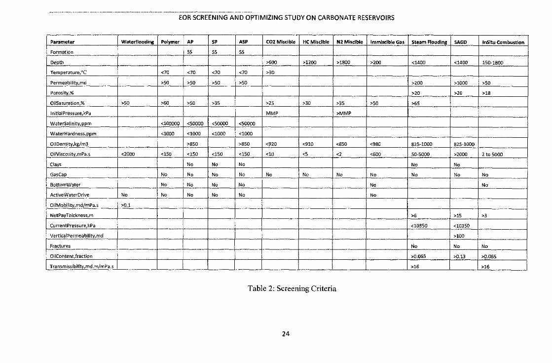
By using the properties in the properties on the table below which are from PRize TM
manual, a manual screening will be conducted.
23
EOR SCREENING AND OPTIMIZING STUDY ON CARBONATE RESERVOIRS
Parameter Waterflooding Polymer AP SP ASP C02 Miscible HC Miscible N2 Miscible Immiscible Gas Steam Flooding SAGO lnSitu Combustion
Formation ss ss ss
Depth >600 >1200 >1800 >200 <1400 <1400 150-1800
Temperature,oc <70 <70 <70 <70 >30
Permeability,md >50 >50 >SO >50 >200 >1000 >50 -Porosity,% >20 >26 >18
Oi!Saturation,% >50 >60 >SO >35 >25 >30 >35 >SO >6S
lnitiaiPressure,kPa MMP >MMP
WaterSalinity,pprn <100000 <50000 <50000 <50000
WaterHardness,ppm <1000 <1000 <1000 <1000
Ol!Density,kg/m3 >850 >850 <920 <910 <850 <980 82S-1000 82S-1000
OiiViscosity,mPa.s <2000 <150 <150 <150 <150 <10 <5 <2 <600 S0-5000 >2000 2 to 5000
Clays No No No No No
Gas Cap No No No No No No No No No No No
BottomWater No No No No No No
ActiveWaterDrive No No No No No No
OiiMobility,md/mPa.s >0.1 !
-NetPayThickness,m r-----1--- >6 >1S >3
CurrentPressure,kPa --r-------- ---- <10350 <10350
Ve rtica IPermea bility, md >100 --Fractures No No No - -OiiContent,fraction >0.065 >0.13 >0.065
l T~~nsmis~lbility,md_~/mPa_.s __ -- ------· --- -- ~--L_ ----- - ----- - ~- ~- ·~
>16 >16
Table 2: Screening Criteria
24
--------------------------------EOR SCREENING AND OPTIMIZING STUDY ON CARBONATE RESERVOIRS
The result can be obtained by compming the properties in table and the properties of the
fields selected.
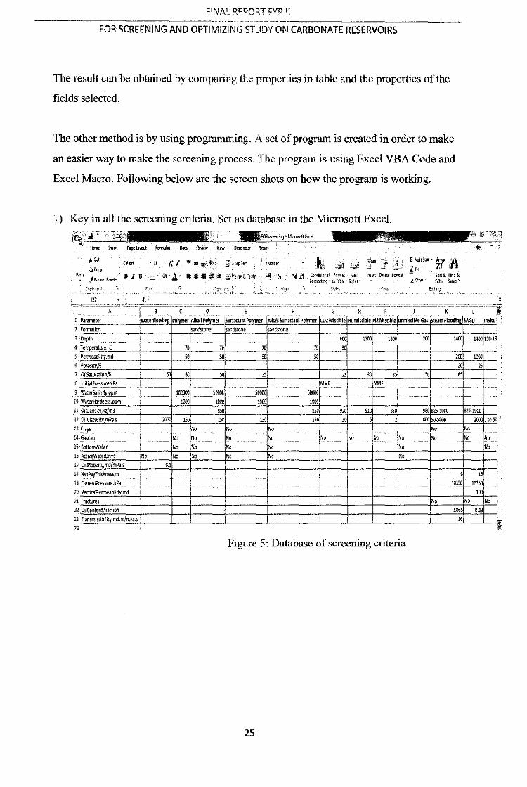
The other method is by using programming. A set of progrillll is created in order to make
an easier way to make the screening process. The progralll is using Excel VBA Code and
Excel Macro. Following below are the screen shots on how the progrillll is working.
1) Key in all the screening criteria. Set as database in the Microsoft Excel.
}let
~JC~~ .... • JF;,r·~,rt~!f
(',:~n'J
·l,f!uo~llbl:el
CCMW~nil farrn1t (~II
r~~~~q" o\ Tiblc ltJ~tJ•
:"-''- -,21- c • f, lee <=''' •="-'''·- ·• ccc•?'=•=o.• =•••''""''''c = '"'-' c. • •= o == '"-'" c ' •• cc= • c -, _____ _
A . I__ D E G H I j K L 1 Parilllleter
2 FormaUon
Polymer Albn Polymer jStufartant Polymer IA!bn Smfartant Polymer COl Miscible HC Ml~ible Nl-Mi~lb!e llmmisdbie Gas steam Flooding SAGO l~a~dsto,1e .sandstone
3 O€:pth ~ 600 UOO 1800 200 1400 1400 15iJ.IS: ' .~~~m~,,-m-,.-,,.~c----~------+-~m+-------ro -------m+.--------~m+----~30~--~--~~----~~--~~~~~.
5 Permeabilit'f,md 50 5D 501 50
7 OilSatur.;Uon.~~
S lnitia1Pr<!>$Ure,kPa
9 W.JoterSalini!)<,ppm
10 WaterHardness,ppm
11 OiiOensity,kg/ml
12 OliVisrosirJ,fllDa.s 13 Clays
14 GasCap
n aonamWater
15 Activewa:erOrwe
li Oi!MODlhty,md/mPa.s
18 NetPavTi',!t~ness,m
19 Currenwress~re,kPa
20 Vertn:ol!Permeability,md
Zl Fractures
12 O!IContent.fmtiM
jNO
23 Transmissibi!it~.md.m/mPa.s: 24 !
2001)
,_,
" !OCOOJ '""" !000 1000
!!50
15U l5{;
'" No No
No NP
No No
" No
No
No
l5
1000
150 )No
\No !No
"
""" 1000
"" 1~
" MMP MMP
910 SlO 850
10 , 1
No No
i i
Figure 5: Database of screening criteria
25
980 825·1000
""50-5000 No
No
NP
200 1000
20 "
"
825.1000 2000 2-:oW -';
" No ~D
No
" 10350 10150
100
No No
0.065 O.B
l6
l

EOR SCREENING AND OPTIMIZING STUDY ON CARBONATE RESERVOIRS
2) Coding the program using VBA-Excel Macro
fl!ol!ug ltiln !ool<; Ad<l-lln :!in dew.'. Hd~ '""''''"'''
Jl ,] !l ~ j' ·~ ; - =~t~,;~~-=-=-<==±...:.... __ :::f=:,· =="'CiCC::c::;c::;=====================:~,-~ ~claraliom) ~
l. :---,,--
"~~ertloodi~~ ~ "~~ernocri.!ra - 1 I::d lt If S:O,ee,es l"iJser!np::t") .Cell! 1~6, "dnl . Vel"" ~ 5he~u ("0.\tlllue") .Cell~ 1-'.<, "l::~) .VeL~
T-'l~"' "~terflaOdi:!Q' ~ w~terflc~dir.g ~ 1 En~ !f
Ihe:~
End H
watertlootlir.q ~ waterncedir.g ~ ~ '"'~~ :·..:~::::_.._-,
End 1t
;:cl~=r " {!cl~v.er f 1 E;~d If
;:ol:;v.r ~ t:el>'IU!r + 1 E~d !f
I'Oll=r ~ ;:ol:,'ll:er + l '<·oot=r s~~;~.:t~·
E::cl It
Figure 6: VBA Coding
3) Create the user input interface and result area.
4
' " u 12
B
" "
Parameter
Formation
Oepth,m
T~mper<rture. C Permeabi!rt ,md Porosi ,% Oii Sat.,r;~tion,% Initial PTessure,kPa Wal"'r Salif>ity.ppm
wat...- Hardne->~,ppm Oil Den;· ,k m3
Oil Visco;ity,mPa.~
Clays
Gasca Bottom Wilter
!'_':!IJ.f!' Walf!'.!:.Q.~~~ Oil Mobih1y.mdf.mP<>.s
Ne1 Pit' Thtd<ne.~s.m
Curr<>nt Pre.!~ure.,k oa
Vertical Pe.rme.atlility,md
Fraaure,s
• • =· ~·- ~WrapT!!>t
IF. ;.: ~ ~ ~Morg~t<C<'nW-
G
Vatue
Figure 7: User input
26
H
-;.~ ~~ -~ C~nd<lu>"al For:n.>t C· f<.>rrnatbn!f• a< Tabt~ • Styl
SCREEN
--~~----'

FINAL REPORT FYP II
EOR SCREENING AND OPTIMIZING STUDY ON CARBONATE RESERVOIRS
For example, dolomite reservoir at San Andres is tested using this program. After the
user key in all the data in the value column. click the screen button and the
result will show.
~~-~~ ........................................ ~~ - -- l!lell ~~ ,....... ~ .... ,... ~ ., - - y
c-
• I a · II ,;\.' • • • • • • ~-... -.. tJ j ·r i E ~;::- · i r Jl
•••w• :iJ ...... ac.. • !f-. • ~~ ~-.:=·-=· ~~·-=- -tOtat• ::.~::S&.
""" -0
--7
"' ll
u u lA u .. 11 I II
$(JIQH
" II> c:=J n Z2 D ;M
Z5 ·-"4. tl -.!'-ll ':J
Figure 8: User input and result
The example result above shows the suitability percentage for each method. From the
result, a feasible method for the field can be predicted.
Q
From the technical screening above, a bar chart can be developed for each field to
analy7e the percentage suitability of each method. Figure 9 he low shows the result for the
test.
Vacuum, New Mexico (San Andres)· Dolomite
57% 60.,.,
43%
8% 8"' 10%
o·:;. o% o•'
Figure 9: Vacuum, New Mexico (San Andres) - Dolomite
27

FINAL REPORT FYP II
EOR SCREENING AND OPTIMIZING STUDY ON CARBONATE RESERVOIRS
After each field is tested, a trending for example for dolomite reservoir can be figured out
and ready to analyze as discussed in result and discussion chapter.
.Ne.
I
!
J
~
5
6
7
a
9
IJroloM,it•
-· ---« .........
---~·
Figure 10: Percentage methods for dolomite
3.3 Gantt Chart
The key milestone and propose planning throughout this semester activities are as
follow:
DlaitWHl ........ • 9 II 11 I! u 14
Pro,ect won: c 011111111n
'n(~\ R.epon • l'ro)ect Wod: C OOIIDIItS
.:L. illl't·EDX 1':1 • ~
!0 I oforul llepon ..
~ • <II tl
I Of I ( IC)ft boiiDd) E _. tl
II: I
1 01 1«11111C11 PJptr ,
__! ~
pal •
IS
t ofProJK! l (lbrd Bouod) _t_ j
Table 3: Gantt chart
28

FINAL REPORT FYP II
EOR SCREENING AND OPTIMIZING STUDY ON CARBONATE RESERVOIRS
CHAPTER4
RESULT AND DISCUSSION
After doing the technical screening for several types of fields. the results gained are discussed
as follow. Since there are three types of carbonate reservoirs v.hich are calcium carbonates,
dolomite, and limestones. the results are divided into three section.
The technical screening that have been done are ba~ically divided into tour methods based on
the project fields data. They are C02 floods, HC floods, N2 floods, and chemical methods.
For gas injection, the fields projects are based on continous injection or WAG while the
chemical method includes surfactants or polymer floods.
The EOR fields projects that arc from carbonate reservoirs in US and one from the North Sea
which is Ekofisk Field.
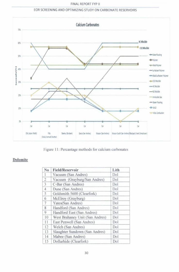
Calcium Carbonates
Table 5 below shows the field and reservoir for calcium carbonates lithology that have been
tested.
Field/Reservoir Lith Old Lisbon (Pettit) Car Fitts (Viola,Cromwcll.Hunton) Car Stanley (Burbank) Car Garza (San Andres) Car Wasson (San Andres] Car -Wasson South (San Andres) Car Blackjack Creek (Smackover) _ Car -
Table 4: Calcium carbonates reservoirs
From the technical screening, the result for each field and methods arc recorded in percentage
and is ilustrated in the graphs below.
29
I~
FINAL REPORT FYP II
EOR SCREENING AND OPTIMIZING STUDY ON CARBONATE RESERVOIRS
Calcium Carbonates
~------~----~oc~ ,_------t------t COlMiscillf
tr
.... t~i·~·
-54..:0::~~·
-:.b~ Poi\Trt!
+C02~
ct• •e ':=J l!n)(SI..,tll'll G¥:~·5.an.~.t--Crts) Yil!l:)l:lif1.llldru1 t.'Oliol..ft.lSr ~~tsle,Jr\;rlCrttl l!rmt1l ~'lCrQ~~Y.tft 'ivr~J
J 'igure 11 : Percantage methods for caJciwn carbonates
Dolomite
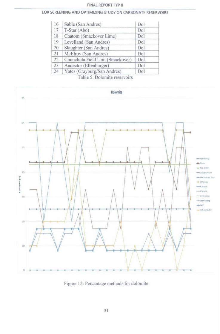
No Field/Reservoir Lith 1 Vacuum (San Andres) Dol 2 Vacuum (Grayburg/San Andres) Dol 3 C-Bar (San Andres) Dol 4 Dune (San Andres) Dol 5 Goldsmith 5600 (Clearfork) Dol 6 McElroy (Grayburg) Dol 7 Yates(San Andres) Dol 8 Handford (San Andres) Dol 9 Handford East (San Andres) Dol 10 West Brahaney Unit (San Andres) Dol --11 East Penwell (San Andres) Dol 12 Welch (San Andres) Dol 13 Slaughter Sundown (San Andres) Dol 14 Mabee (San Andres) Dol 15 Dollarhide (Clearfork) Dol
30
FINAL REPORT FYP II
EOR SCREENING AND OPTIMIZING STUDY ON CARBONATE RESERVOIRS
16 Sable (San Andres) Dol 17 T-Star (Abo) Dol 18 Chatom (Smackover Lime) Dol 19 Levelland (San Andres) Dol 20 Slaughter (San Andres) Dol 21 McElroy (San Andres) Dol 22 Chunchula Field Unit (Smackover) Dol 23 Andector (Ellenbui"g_er}_ Dol 24 Yates (Grayburg/San Andres) Dol
Table 5: Dolomite reservoirS
Dolomite
..... t.n·~...,
+ ):.!'"' '"
...... J. 'b JJ.\ft'f•
~ - 'At·trt•n,_. . - .:.u W'!iCJ't 11))'11'
; -+-C,):Vtsth 1
- -,.\!>ttl< E ' -~u.= -
l3\ -'f!ftV~'-'i
...-~·u.,."'«G'I
+ W.:l ... ~,__.,.. :;,
Figure 12: Percantage methods for dolomite
31

FINAL REPORT FYP II
EOR SCREENING AND OPTIMIZING STUDY ON CARBONATE RESERVOIRS
Limestone
No Field/Reservoir Lith 1 Phosphoria (Wcsgum A) LS 2 Tonti (Renoist Auxvases McClusky) LS 3 Trapp (Lansing/Kansas City) LS 4 Bates Unit (Mississippi) LS 5 Harmony Hill (Lansing/Kansas C'ity) LS 6 Dry Creek (Lansing/Kansas City) LS 7 Blue Buttes (Madison) LS 8 Fitts (Viola) LS 9 Balko South (Kansas City) LS 10 Garza (San Andres) LS 11 Cottonwood Creek (Phosporia) LS
~-
12 Corossett (Devonian) LS - -13 Wellman (Wolfcamp) LS
- -14 Codgell (Canyon Reef) LS -15 Aneth (Ismay Desert Creek) LS 16 Ekofisk (Norwegian Sector) LS 17 Carlson (Madison) LS 18 Red Wing Creek (Mission Canyon) LS 19 Fairway (San Andres) LS 20 Wolfcamp Univ Block ( (Wolfcamp) LS 21 Block 31 (Devonian) LS 22 Jay-Little Escambia Creek (Smackover) LS
Table 6: Limestones reservoirs
32

FINAL REPORT FYP II ------------------------------------ ----------------------- ----------
EOR SCREENING AND OPTIMIZING STUDY ON CARBONATE RESERVOIRS
Limtstone ;;r~
- v.,.....,.... - u. ,s..-.llfow•
- ..:-
• •
Figure 13: Percantage methods for limestone
33

FINAL REPORT FYP II
EOR SCREENING AND OPTIMIZING STUDY ON CARBONATE RESERVOIRS
Limestone/Dolomite
No Field/Reservoir Lith 1 Reinecke (Cisco Canyon Reef) LS/Dol 2 Hilly Upland (Greenbrier) LS/Dol
Table 7: Limestone/ Dolomite reservoirs
Limestone/Dolomite
------------------------------------~ ·ft~~.\
~s.;., .. , -;e ... -oe. 0\ --------- ~ ........... ... t.":'o ...__~~ ... t:t-·• ·0\
Figure 14: Percantage methods for Limestone/Dolomite
34
PNAL REPORT cyp '1 -----------~ ------------------------------~
EOR SCREENING AND OPTIMIZING STUDY 0~1 CARBONATE RESERVOIRS
Based on the result shows above, on the teclmical screening using the EORscreening, the
programming software which developed using the visual basic Microsoft Excel 2007 Macro
and the data gained from E.E Manrique et al. (2007), the most suitable methods for calcium
carbonates, dolomite, and limestones are HC Miscible, COz Miscible, Polymer and Nz
Miscible. Comparing with the research made by E.J Manrique et al. (2007), C02 flooding has
been successful in the both mature and waterflooded carbonate reservoirs. The use of COz is
definitely popular among the oil companies because of the affordability and availability of
C02 rather than the other methods (E.J Manrique et al., 2007). Although the HC Miscible is
showing the most suitable for the reservoirs, but for the economic purposes, it is more
profitable to sell the gas immediately. HC gas is the better choice when it is available in
sufficient quantities and non economical to export (A.R A wan et al., 2008).
For Alkali Polymer, Surfactant Polymer, and Alkali Surfactant Polymer, they show 0% for
each test based on the EOR screening database as they are not suitable for carbonate
reservoirs but for sandstone only. It is because the use of surfactant in chemical methods
needs co surfactant, mostly alcohol. Alkali in carbonates makes will increase the chemical
absorption within the rocks because of the different charges. In other cases, polymer are
widely use because it uses the water-soluble polyacramides in other to control the mobility of
water during waterflooding (E.J Manrique et al., 2007).
Waterflooding shows 25% for each as the fields at first will initiated to improve the recovery
by injecting water. After certain time, the water will bypass the oil since the highly fractured
of carbonate reservoirs. Therefore, another method needs to be implemented to overcome the
problem. Injecting gas or polymer is proven as the best solution to control the mobility of oil.
C02 flooding, either continuous or WAG is the dominant EOR process used in the US while
in chemical method, polymer flooding is highly tested in the US (E.J Manrique et al., 2007).
The use of C02 is also the first step taken by the oil companies towards the viable geological
carbon storage and sequestration. Furthermore, with the current focus on C02 emissions,
EOR by C02 injection is considered attractive and will be the main focus for future research
programs. WAG can be used when the gas is available in sufficient quantities and non
economical to export while SWAG can be considered when the injected gas is available in
limited quantities. With the current oil price, the use of polymers also could be possible in
carbonate reservoirs (A.R A wan et al., 2006).
35
~~~ ---~~-~---~-------------
EOR SCREENING AND OPTIMIZING STUDY ON CARBONATE RESERVOIRS
CHAPTERS
CONCLUSION AND RECOMMENDATION
5.1 Recommendation
The results that gained from this project and data that has been used can produce the
new criteria for screening criteria. This means that the screening criteria for carbonate
reservoirs can be improved. The continuing study on this project can produce a good
database system in choosing the suitable EOR method for carbonate reservoirs.
Based on the discussion above, the most probably suitable EOR methods that can
implemented in carbonate reservoirs are HC Miscible, C02 Miscible, Polymer
Flooding, and N2 Miscible. But, there are certain limitations for each method.
Waterflooding is always the best secondary type of recovery since the economical
value and the process is easier to be implemented. Tertiary recovery or EOR will
come after that since the waterflooding alone will sooner create to more residual oil in
the carbonate reservoirs. Therefore, gas injection and chemical injection can help to
reduce the residual oil and increase the mobility of oil in the reservoirs. Then, to
choose the suitable methods, screening criteria on the properties and economic value
must be conducted.
As per discussion above, the recommendation for suitable methods for carbonate
reservoirs can be made. Based on the technical screening and history on successful
project, the most preferable method for carbonate reservoirs is C02 flooding either
miscible, continuous, or in WAG. C02 is proven as the dominant method in
carbonate reservoirs in US because the availability and low cost (E.J Manrique et al.,
2007). Other than that, the use of C02 also can reduce the excessiveness of the gas to
the atmosphere, and then prevent the global warming.
36
------------ ·-···-··---""-----·-------------EOR SCREENING AND OPTIMIZING STUDY ON CARBONATE RESERVOIRS
5.2 Conclusion
As for the conclusion, this project helps to determine the best solution ofEOR
process in carbonate reservoirs. All the data on the specific reservoirs has been
screened and the EOR process applicable for that reservoir can be selected as the
most promising EOR process that can improve the production of carbonate reservoirs
recovery. The screening test has been conducted by using manual screening and also
the programming based database on previous successful project.
37

~-~~~~---~~-----~-------------
EOR SCREENING AND OPTIMIZING STUDY ON CARBONATE RESERVOIRS
REFERENCES
Allan J. And Sun S.Q. 2003, "Controls on Recovery Factor in Fractured Reservoirs: Lessons Learned from 100 Fractured Fields", paper SPE 84590, presented at the SPE Annual Teclmical Conference and Exhibition, Denver, 5-8 October
A.R. A wan, R.Teigland, and J.Kleppe. 2008, "A Survey of North Sea Enhanced Oil Recovery Projects Iniatiated During the Years 1975 to 2005', paper SPE 98546, presented 2006 SPE/DOE Symposium on Improved Oil Recovery, Tulsa, 22-26 April.
A. Skauge et al., "Foam for Gas Mobility Control in the Snorre Field : The FA WAG Project". SINTEF Petroleum Research, paper SPE 78824, presented at the Annual Technical Conference and Exhibition, Houston, Texas. (Oct 1999)
Bandar Duraya AI-Anazi, "Enhanced Oil Recovery Techniques and Nitrogen Injection", King Saud University,Riyadh,Saudi Arabia, October 2007
David B. Burnett and Michael W. Dann, "Screening Tests for Enhanced Oil Recovery Projects", paper SPE 9710, presented at tt'le 1981 Permian Basin Oil and gas recovery Symposium of the Society of Petroleum Engineers of AIME in Midland, Texas, March 12-13.
Department of Petroleum Engineering Louisiana State University, "Post Waterflood C02 Miscible Flood in Light Oil Fluvial Dominated Deltaic Reservoirs", submitted to Texaco E&P, Inc. December 1996.
E.A. Quale, B. Crapez, J.A. Stensen, "SWAG Injection on the Siri Field- An Optimized Injection System for Less Cost", paper SPE 65165, presented at 2000 European Petroleum Conference in Paris, France.
E. Manrique, Mariano Gurfinkel, Viviana Muci, " Enhanced Oil recovery Field Experiences in Carbonate Reservoirs in the United States", 25th Annual Workshop & Symposium Collaborative Project on Enhanced Oil Recovery International Energy Agency, September 5-8,2004.
E..T. Manrique, V.E. Muci, M.E. Gurfinkel, "EOR Field Experiences in Carbonate Reservoirs in the United States", paper SPE 100063, presented at 2006 Symposium on Improved Oil Recovery at Tulsa, 22-26 April.
E. Manrique and J. Wright, "Identizying technical and Economic EOR Potential Under Conditions of Limited Information and Time Constraints", paper SPE 94682, presented at 2005 SPE Hydrocarbon Economics and Evaluation Symposium in Dallas, TX, USA, 3-5 April.
E. Manrique," Enhanced Oil Recovery (EOR): Trends, Risks, and Rewards", presented at the ACI Optimising EOR Strategy 2009, London, UK, 11-12 March, 2009.
F.E. Suffridge, K.T Raterman, and G.C Russel, "Foam Performance under Reservoir Conditions", paper SPE 19691, presented at 1989 64th SPE Annual Teclmical Conference and Exhibition, San Antonio.
38
----------- -----------EOR SCREENING AND OPTIMIZING STUDY ON CARBONATE RESERVOIRS
Han Dakuang, "The Achievement and Challenges ofEOR Technology for Onshore Field in China", Research Institute ofPetrolemn Exploration and Development, Beijing, China.
J. Brian Magruder, Loren H. Stiles, and Thomas D. Yelverton, "Review of the Means San
Andres Unit C02 Tertiary Project", JPT May 1990.
J.J Taber, F.D Martin, and R.S. Seright, "EOR Screening Criteria Revisited-Part l: Introduction to Screening Criteria and Enhanced Recovery Field Projects", paper SPE 35385, presented at I 996 SPE/DOE Improved Oil Recovery Symposium in Tulsa, Oklohama, 21-24 April.
Marcel Latil, "Enhanced Oil Recovery", Edition 1980 Technip, Paris, Gu1fPublishing Company Book Division, Houston, Texas.
Matheny, Shannon L. "Production Report Enhanced Oil Recovery". Oil & Gas Journal, March31. 1980.
Mayank Srivastava and Quoc P. Nguyen, "Application of Gas for Mobility Control in Chemical EOR in Problematic Catbonate Reservoirs", paper SPE 129840, presented at 2010 SPE Improved Oil recovery Symposium held in Tulsa, USA, 24-28 April.
Moritis, G.," Report on Enhanced Oil Recovery". Oil & gas Joumal, April12, 2004.
M. Trujilo, D. Mercaso, G.Maya, R.Castro, C.Soto, H. Perez, V.Gomez and J.Sandoval, "Selection Methodology for Screening Evaluation of Enhanced Oil Recovery Methods", paper SPE 139222, presented at 2010 SPE Latin American & Caribbean Petroleum Engineering Conference in Lima, Peru, 1-3 December.
Noran, D. "Enhanced Oil Recovery Action is Worldwide". Production Report Oil & gas Journal, AprilS, 1976.
Nguyen, Q.P, 2004. "Dynamic of Foam in Porous Media". PhD Dissertation. Delft University Netherlands.
Qamar M. Malik and M.R Islam, 2000. "C02 Injection in the Weyburn Field of Canada: Optimization of Enhanced Oil Recovery and Greenhouse Gas Storage With Horizontal Wells", paper SPE 59327, presented at 2000 SPEIDOE Improved Oil Recovery Symposium in Tulsa, Oklahoma, 3-5 April.
Roehl, P.O. and Coqueete, P.W. 1985, "Carbonate Reservoirs", New York City: SpringerVerlag.
Sarma, H. K.: "Gas Processes: Principles and Field Application," Japan National Oil Corporation, Chiba-Shi, Japan 1999.
Seethepalli, B. Adibhatla, K.K Mohanty. "Wettability Alteration During Surfactant Flooding of Carbonate Reservoirs", paper SPE 89423, presented at SPE/DOE 141
h Symp. On lOR Tulsa, 17-21 April2004.
39

EOR SCREENING AND OPTIMIZING STUDY ON CARBONATE RESERVOIRS
S.M. Farouq Ali, "Appraisal of Micellar Flooding, Carbon Dioxide, and Surfactant Flooding Projects", paper SPE 6624, presented al977 Society Petroleum Engineers AIME Eastern Regional Meering in Piiisburgh, Pennsylvania, October 27-28.
Spinier, E.A and Baldwin, B.A, 2000 ''Surfactant Induced Wettability Alteration in Porous Media". In Surfactant Fundamental and Application in the Petroleum Industry, ed. L.L. Schramm, Cambridge, UK: Cambridge University Press, 159-202
T.Babadagli, " Selection of Proper EOR Method for Efficient Matrix Recovery in Naturally Fractured Reservoirs ",presented at SPE Latin American and Caribbean Petroleum Engineering Conference held in Argentina, 25-28 March 2001.
T.B. Jensen, K.J. Harpole, and A.Osthus, "EOR Screening for Ekofisk", paper SPE 65124, presented at SPE European Petroleum Conforence held in Paris, France, 24-25 Oktober 2000.
Vladimir Alvarado and Eduardo Manrique, "Enhanced Oil Recovery: An update Review",
Energies, 2010 (1529-1575).
Wen Gao, H. "Mobility Control in Oil Recovery by Chemical Flooding State of the Art Review". National Institute for Petroleum and Energy Research (Report NIPER-146), January 1987.
http://www .netl.doe.gov /techno! ogies/oil-gas!EP _Techno logies!Exploration Technologies/
Yongfu Wu, Patrick J. Shuler, Mario Blanco, Yongchun Tang, and William A. Goddard III," An Experimental Study of Wetting Behavior and Surfactant EOR in Carbonates With Model Compounds", paper SPE 99612, presented at 2006 SPE/DOE Symposium on Improved Oil Recovery, Tulsa, 22-26 April.
40
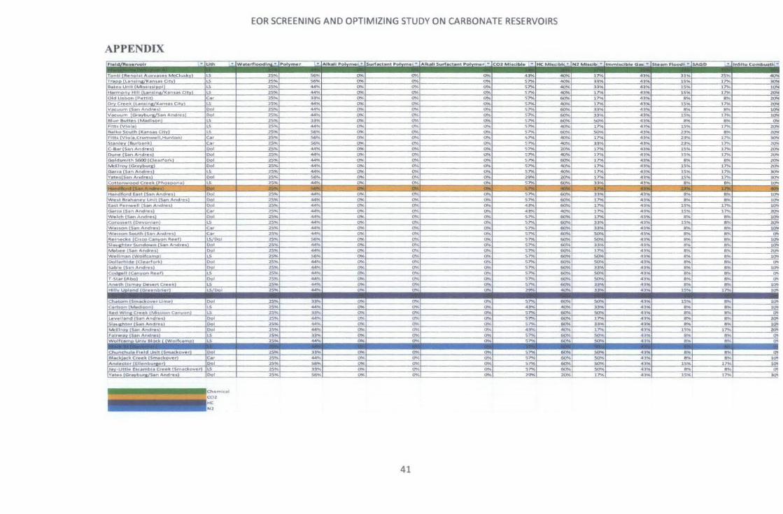
APPENDIX
To_~~l_l~~t~~~~~-~-u~v_•t•-~ ~lu:d~lil_ T<o
.-..rmon Hill t..n-.1 Old lisbon Pet11t
Dry c,.. • ._ (l~ntln&/K•n••• City)
IVatuum IGr~raJ'S•n And,..,' atu,. Buttet. l"-"-d••on)
&.iko South (K•ns•• City) Fltlt. (VIole.
C-lbr S•n Andres
Dune (S•n Andr•s)
(Mdlroy [Gf'aybur1) ~ria--t"sa-~Andre.,
'•"tesiS•n And,...tl Cre•k
t~::~:;~:~;~~.!d, .. : LWelch l~.-n _A~r••l cOnn-satt (D•Y-onl•ril lwauon (S•n Andres)
Codl•ll (Canyon~ •• ,, r-~tM(Abol
~~~ IHIIIv Upl•nd
ChUOfT\ (\fft.ad!Gvttr t
lc.nson (~••on, fled Wlrta Cr••k tf'IAiuiaf'l Ca"'YYt'l)
Rtacil Hk Cr••k Andaetor ((ll•nburaar)
IY•t•• ,Andres]
··(Uth
~ L5 u ""' )OL
""' rc.;
t>ol ;or )91_
)ol
ro;;T C.•
(Dol (LS ,., "" u_no1 )ol
(Dol
L5
~·-lS/Ool
L5 L;"
(Dol ;;;;-
~
~ ILS
jo·. . ' ., Ch•,•ol CO>
I HC N2
EOR SCREENING AND OPTIMIZING STUDY ON CARBONATE RESERVOIRS
,,.otyrn.r ·~JAik .. l Pofytne·_~ lsuttact.n·t ,ofym•• ·(~Uic.MI Surf.ct .... t P'otyrner- ·IcOz. MlKibie -... THe Mt;dbi~--;-,Nz-MIKib-- hml'l'lbdbtlt o-.-"' 151.-W...FtOad-.-.;. fsAGD
.,;,. .... ~ .,;,. _.,; .. 2.!
~ 25 ..
-rn;:
2~
""' ....
25" .,;,. ~,._
.,;,.
25" 25 ..
2S" 25"
2$1J(o -rn<
25 ..
....
..,.,.
25 ..
.,;,.
.... ..... .... "" .... ........ ~ .2!!!.
44 .. ..... -;
~ 44 .. .... ....
--.e;; ---...;-
~ .... ~~ ....
-~~ .. ... """' ......
---;;;;
u.. ........ -;;;; .... -.:..;; ---...;-~ ---...;-
..... --;;;;;;-
,....
"" "" IN "" ~ 00<
"" "" IN
""' c;;; OK
""" a;;;
""'' "" ---.;;; OK
"" a;;; c;;;
"" "" "" IN
...!!!!:
"" "" a:;;:
"""
"" "" "' 01
m
"' m "" .... ""
--.;;;<
"" --.;;;< --.;;;< IN IN
~ -IN
"" IN
~
""' ""
~
"" ~
"" "" c;;.:
.. 0
.... --.;;;;
""'
"" ""
41
,.. ... ~ ~
""' .~
""' "" a;;
"" a;;
""'
"" "" IN
.... .... IN ---u;;;
"" --;;;;
""
""' ""
·~ .,. 51'M .,.,. S1'M ...,.. ·-~ .,. ~ S"1%
S1'M
~-........ .,. ..... ·-.... S"1%
·-~ 5706
s-
4.
""'iN
·-,,.. .....
--..,..
--.o;;:
..,.. ""liM ..,.. ~
..,.. -.o;o ""liM -..,..
_..,.. ""' ""liM 6010
""liM
..!'!!!
""" --eo;o ..,.. 00
6ii 6ii
"" --eo;o
6010
-..,..
·-.... ....
tN
~ ..,.. ..... iN
·-iN
·-·-, ...
-jy,.,
..,.. """' ..,..
-;o;;
"""
""" J ....
..,.. ~ ,.,..
_4l'K .... "'4j; ........ -.o; ""'4);C
~ 41"
~ 4l ..
4 ... 4}';i
.... -. 3:
4
4 ~ ... ~-~ ... 4N ..... .. ... ~
41 --;;
~· ..... ~.... ..... .... ...... ~ ...
--;;;; -.-;;;;; ...... 4N ~ ~ •t•
"" ,.,. "" u .. .... .... -~ ~ -
...ll:!! n" ,. ... is% .. ...
"'" .... ~ ... ~ .,.
--... ~ --.... .. .. ..!!! --""""
....
.....
-• J•nSttU cOmt.u.u.-
25~ ,.,. rn:; ,,.. ~
''"" ,,., ... ~ ~ ,,.,. ,,.. rn;: ,,. ,,.. v;;: -..;:
-~ --~ .,. ~ ... ~ ... ;;;; .,. ;;;; --,,.,. ... ... ... ...
-.,;; ...... ... ....!!!. .... -~ ,,..
-)0'0
--..:;; """"iOi """"iOi """"iOi 7 .!.!!S .....!!.!!
2001
~ ..,. lOii ..,...
2001 ..,... ..,... -..,.. '""'
__!Q'I<
>c u;;o
'"" -.;;; __!!! ...!!!! ,.,.. ....
10'1 ""iii' o; ..,.