
ENVIRONMENTALLY FRIENDLY MOTOR DRIVES MATRIX … · ENVIRONMENTALLY FRIENDLY MOTOR DRIVES ......
35
YASKAWA 200V CLASS 5.5kW to 45kW 400V CLASS 5.5kW to 75kW MATRIX CONVERTER ENVIRONMENTALLY FRIENDLY MOTOR DRIVES Varispeed AC Certified for ISO9001 and ISO14001 JQA-EM0498 JQA-0422 ENVIRONMENTAL SYSTEM C E R T I F I E D M A N A G E M E N T S Y S T E M QUALITY SYSTEM C E R T I F I E D M A N A G E M E N T S Y S T E M
-
Upload
trinhtuyen -
Category
Documents
-
view
226 -
download
0
Transcript of ENVIRONMENTALLY FRIENDLY MOTOR DRIVES MATRIX … · ENVIRONMENTALLY FRIENDLY MOTOR DRIVES ......

YASKAWA
200V CLASS 5.5kW to 45kW400V CLASS 5.5kW to 75kW
MATRIX CONVERTERENVIRONMENTALLY FRIENDLY MOTOR DRIVES
Varispeed AC
Certified forISO9001 andISO14001
JQA-EM0498JQA-0422
ENVIRONMENTALSYSTEM
C
ER T I F I ED
MA
NAGEMENT SYST
EM
QUALITY SYSTEM
C
ER T I F I ED
MA
NAGEMENT SYST
EM

The storm has finally cleared, revealing a rainbow stretched across the sky.The Varispeed AC Matrix converter pushes back the clouds to lead a new age of technology.The Varispeed AC incorporates innovative technology as the world’s first matrix converter to directly convert input AC voltage to output AC voltage. The Varispeed AC not only improves energy efficiency, but also overcomes many problems typically associated with conventional general-purpose inverters.
(Some models pending)
Blue Sky &Blue Sky &Green TechnologyGreen Technology
2
C O N T E N T S
Applications 4
Advantages 5
Specifications 10
Dimensions 11
Software Functions 12Connection Diagramand Terminal Functions 14
Protective Functions 16
Option Cards
Peripheral Devices
20
21
Notes 29
Applicable Motors 32
Service Network 35
Varispeed AC (MxC)
Specification Form 34
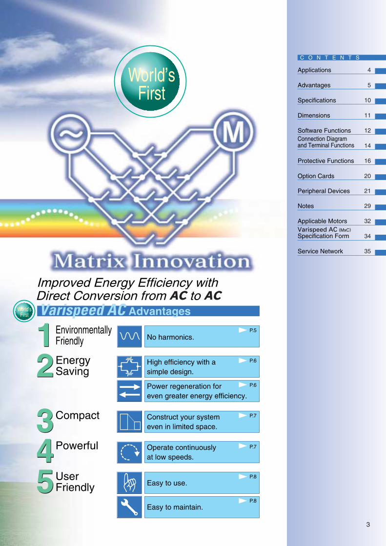
Varispeed AC Advantages
Improved Energy Efficiency withDirect Conversion from AC to AC
World’sFirst
Blue Sky &Green Technology
P.5
World’sFirst
EnvironmentallyFriendly
P.5
P.6
P.6
P.7
EnergySaving
Compact
P.7Powerful
P.8UserFriendly
12
345
12
3345
No harmonics.
High efficiency with asimple design.
Power regeneration foreven greater energy efficiency.
Construct your systemeven in limited space.
Easy to use.
P.8Easy to maintain.
Operate continuouslyat low speeds.
3

Main Applications
Ventilation Fans and Water-Supply PumpsVariable speed applications in hospitals, schools, office buildings, and so on with strict requirements for harmonics distortion.
Cranes, Elevators, and EscalatorsLift applications with heavy repetitive loads and regenerative power.
CentrifugesApplications requiring regenerative power for long periods to decelerate high inertia loads to stop.
Note: Matrix Innovation and the Matrix Innovation logo are trademarks of Yaskawa Electric Corporation.
Input Waveform Comparison with Conventional General-Purpose Inverter
4
Varispeed ACVarispeed AC
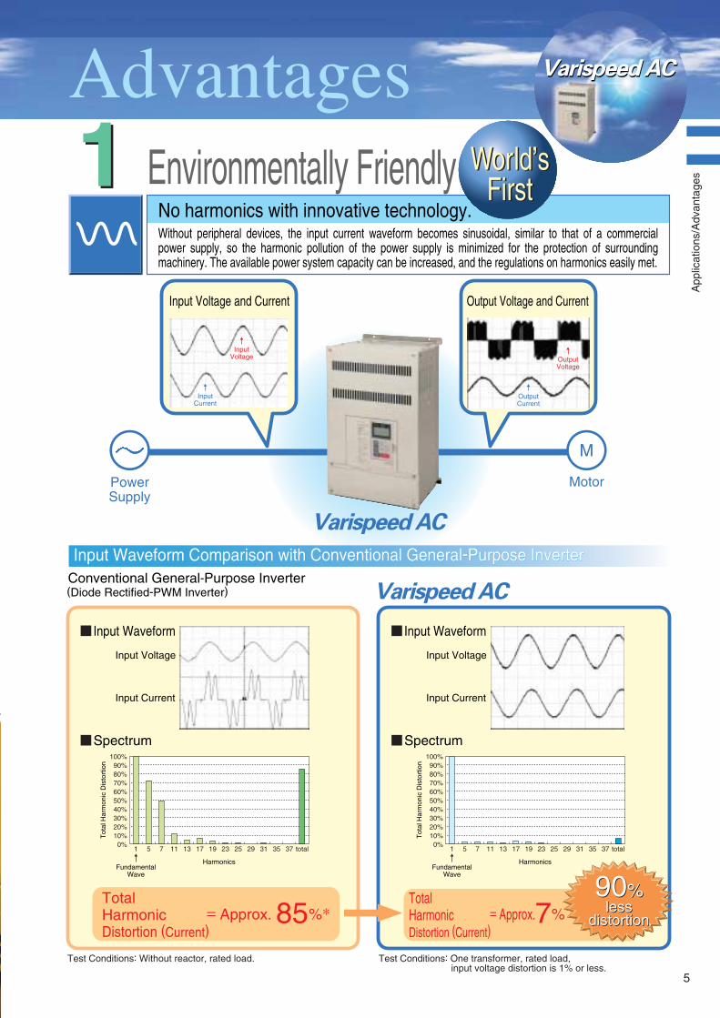
No harmonics with innovative technology.
Environmentally Friendly Without peripheral devices, the input current waveform becomes sinusoidal, similar to that of a commercial power supply, so the harmonic pollution of the power supply is minimized for the protection of surrounding machinery. The available power system capacity can be increased, and the regulations on harmonics easily met.
11Input Voltage and Current Output Voltage and Current
PowerSupply
(Diode Rectified-PWM Inverter)Conventional General-Purpose Inverter
InputCurrent
InputVoltage
OutputCurrent
OutputVoltage
Varispeed AC
.
World’sFirst
World’sFirst
Input Voltage
Input Current
Varispeed AC
90%90%= Approx.
Total Harmonic Distortion (Current)
%85 = Approx.Total Harmonic Distortion (Current)
%7
Input Waveform
Input Voltage
Input Current
Input Waveform
Spectrum Spectrum
Tot
al H
arm
onic
Dis
tort
ion
Harmonics
1
100%90%
70%60%50%40%30%20%10%0%
80%
5 7 11 13 17 19 23 25 29 31 35 37 total
FundamentalWave
Harmonics
1
100%90%
70%60%50%40%30%20%10%0%
80%
5 7 11 13 17 19 23 25 29 31 35
Tot
al H
arm
onic
Dis
tort
ion
37 total
FundamentalWave
lessdistortion
lessdistortion
Input Waveform Comparison with Conventional General-Purpose Inverter Input Waveform Comparison with Conventional General-Purpose Inverter
Motor
M
Test Conditions: One transformer, rated load,input voltage distortion is 1% or less.
Test Conditions: Without reactor, rated load.
App
licat
ions
/Adv
anta
ges
5
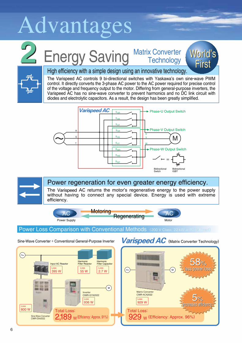
M
Matrix ConverterTechnology
BidirectionalSwitch
BidirectionalIGBT
AC ACMotoringPower Supply Motor
Regenerating
SUR
U
SUS
SUT
SVR
VSVS
SVT
SWR
W
R
S
T
SWS
SWT
Energy SavingHigh efficiency with a simple design using an innovative technology.The Varispeed AC controls 9 bi-directional switches with Yaskawa’s own sine-wave PWM control. It directly converts the 3-phase AC power to the AC power required for precise control of the voltage and frequency output to the motor. Differing from general-purpose inverters, the Varispeed AC has no sine-wave converter to prevent harmonics and no DC link circuit with diodes and electrolytic capacitors. As a result, the design has been greatly simplified.
Power regeneration for even greater energy efficiency.The Varispeed AC returns the motor’s regenerative energy to the power supply without having to connect any special device. Energy is used with extreme efficiency.
22
Phase-U Output Switch
Phase-V Output Switch
Phase-W Output Switch
Varispeed AC
Total Loss:
(Efficiency: Approx. 91%)Total Loss:
(Efficiency: Approx. 96%)
(Matrix Converter Technology)
Harmonic Filter Reactor
Harmonic Filter Capacitor
InverterCIMR-G7A2022
Matrix ConverterCIMR-ACA2022
Sine-Wave ConverterCIMR-D5A2022
Loss
55 WLoss
395 WLoss
2.7 W
Loss
800 W
Loss
936 WLoss
929 W
Input AC Reactor
Varispeed AC
2,189 W 929 W
M
Sine-Wave Converter + Conventional General-Purpose Inverter
World’sFirst
World’sFirst
5%5%increased efficiencyincreased efficiency
58%58%less power lossless power loss
Power Loss Comparison with Conventional Methods (200 V Class, 22 kW at Rated Load)Power Loss Comparison with Conventional Methods (200 V Class, 22 kW at Rated Load)
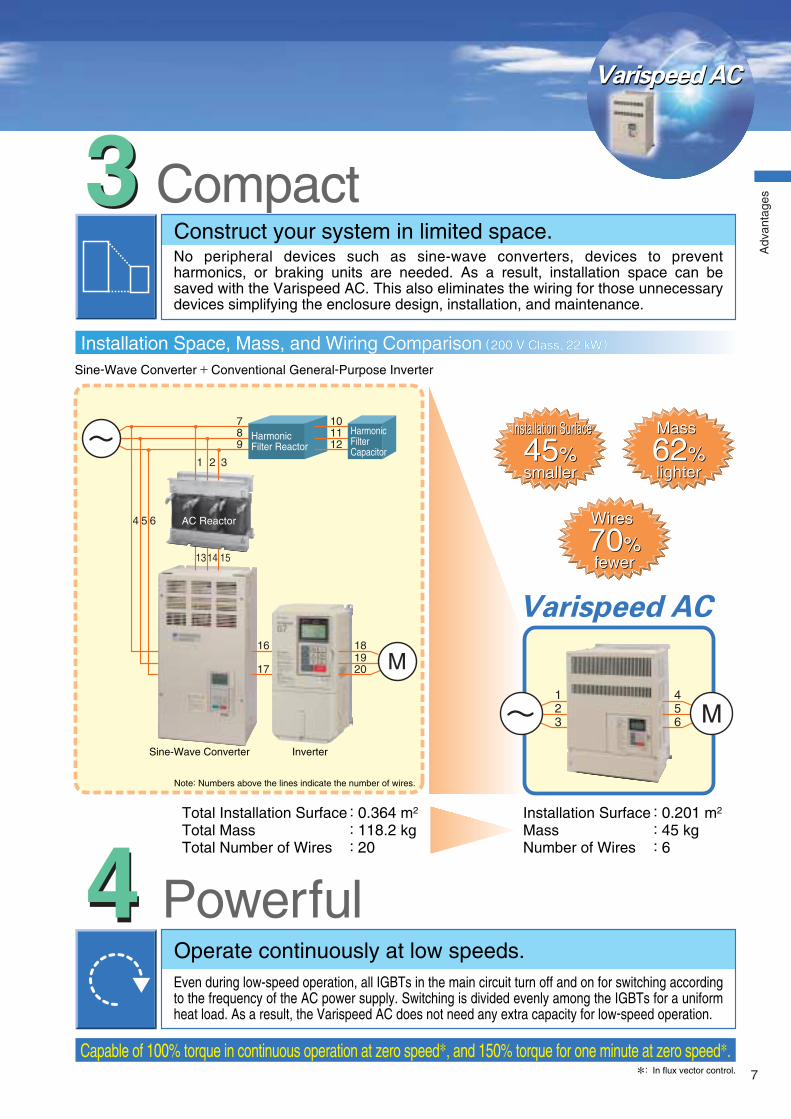
Installation Space, Mass, and Wiring Comparison (200 V Class, 22 kW)
6
Varispeed ACVarispeed AC
Total Installation Surface : 0.364 m2
Total Mass : 118.2 kgTotal Number of Wires : 20
Installation Surface : 0.201 m2 Mass : 45 kg Number of Wires : 6
Note: Numbers above the lines indicate the number of wires.
Sine-Wave Converter Inverter
Harmonic Filter Reactor
Harmonic Filter Capacitor
AC Reactor
1
123
456
2 3
4 5 6
789
101112
1314 15
16
17
CompactConstruct your system in limited space.No peripheral devices such as sine-wave converters, devices to prevent harmonics, or braking units are needed. As a result, installation space can be saved with the Varispeed AC. This also eliminates the wiring for those unnecessary devices simplifying the enclosure design, installation, and maintenance.
33
Sine-Wave Converter + Conventional General-Purpose Inverter
Capable of 100% torque in continuous operation at zero speed, and 150% torque for one minute at zero speed.
PowerfulOperate continuously at low speeds.Even during low-speed operation, all IGBTs in the main circuit turn off and on for switching according to the frequency of the AC power supply. Switching is divided evenly among the IGBTs for a uniform heat load. As a result, the Varispeed AC does not need any extra capacity for low-speed operation.
44
: In flux vector control.
Varispeed AC181920
Installation Surface
45%45%Installation Surface
smallersmaller
Mass
62%62%Mass
lighterlighter
Wires
70%70%Wires
fewerfewer
Power Loss Comparison with Conventional Methods (200 V Class, 22 kW at Rated Load)
Installation Space, Mass, and Wiring Comparison (200 V Class, 22 kW)Installation Space, Mass, and Wiring Comparison (200 V Class, 22 kW)
Adv
anta
ges
7
Model Designation Example Nameplate
No.
A
Specifications
Standard model
CIMR - AC A 4 011
Varispeed AC (MxC)
“P” indicates the decimal point.
No.
2
4
Voltage Class
AC Input, 3-phase, 200 V
AC Input, 3-phase, 400 V
No.
5P5
011
022
045
075
Max. Applicable Motor Output
5.5 kW
11 kW
22 kW
45 kW
75 kW
No.
A to Z
Revision History
Revision (A to Z)
No.
0
1
Protective Structure
Open chassis (IEC IP00)
Enclosed wall-mounted [IEC IP20, NEMA1(Type1)]
4 011 0 A
Model
Input Specifications
Output SpecificationsLot Number
Serial Number
Mass
Software Version
SpecificationsMODEL :CIMR-ACA4011
:AC3PH 380-480V 50/60Hz 26A
:AC3PH 0-460V 0-120Hz 27A 19kVA: MASS : 30kg: PRG : 1030
YASKAWA ELECTRIC CORPORATION MADE IN JAPAN
S P E C : 4 0 1 1 0 A
INPUT
OUTPUTO/NS/N
Conventional General-Purpose Inverter
Sine-Wave Converter+ Conventional General-Purpose Inverter
5-digit LCD makes it easy to confirm information.Quick Mode to operate the Varispeed AC with the minimum parameter settings.Verify Mode to check parameters that have been changed from the default settings.Copy function for easy uploading/downloading of parameters. Set parameters for several matrix converters all at once.Extension cable (optional) for remote operation.
Easily set parameters with the user-friendly digital operator.
DriveWizard, an Inverter support tool, lets you manage parameters on your PC. Manage parameters for each Varispeed AC with a single program, reducing the time required for adjustment and maintenance.Various monitoring functions such as output power, watt-hour, I/O terminal status, fault history, accumulated operation hours, and cooling-fan operation hours.Removable terminals are used for the control circuit so that the Varispeed AC unit can be easily replaced without removing the wiring.Long-life cooling fan with ON/OFF control boosts system reliability.No electrolytic capacitors are required, which would otherwise limit the
Easy to inspect and maintain.Structure is easy to maintain.Enhanced monitoring functions are easy to use.
:Under development.
Configuration of Power-Conversion System No Harmonics Power Regeneration Energy Efficiency Low-Speed Continuous Operation Size
6 Diodes6 Switches
12 Switches
18 Switches(9 bidirectional switches)
User Friendly55
Comparison with Conventional Inverters (Example : Use in Cranes )
Varispeed AC
Matrix Converter
Braking Unit
PWM Inverter
M
Built-in AC Filter
PWM InverterPWM Converter
M
M
AC Filter
Regenerative Power
Rege
nerat
ive Po
wer
Reactor
Easy to use.
Best
Best
Good(Reactor required)
Best Best Best Best
Excellent Best Good(Derating required) Fair
Excellent Not Applicable Good(Derating required) Fair
Varispeed ACVarispeed AC
Adv
anta
ges
98

Specifications
Under development.The maximum applicable motor output is given for a standard 4-pole Yaskawa motor. When selecting the actual motor and MxC, be sure that the MxC’srated current is applicable for the motor's rated current.The rated current will vary in accordance with the values of the voltage or impedance of the power supply (including the power transformer, the input reactor, and wires).Required to reduce the rated output current in accordance with the values of the carrier frequencies or control mode.Rotational autotuning must be performed to ensure obtaining the specifications given for open-loop or flux vector control.The speed control accuracy depends on the installation conditions and type of motor used. Contact your Yaskawa representative for details.Applications with repetitive loads may require derating (reducing carrier frequency and current, which involves increasing the frame size of the MxC). Contact your Yaskawa representative for details.If the CIMR-ACA25P5, 2011, 2022, 45P5, or 4011 needs two seconds or more for the momentary power loss ridethru time, a back-up capacitor unit for momentary power loss is necessary. If L2-01 (Momentary Power Loss Detection Selection) is enabled, the MxC will stop 2 ms after the momentary power loss occurs. Contact your Yaskawa representative for details about use in applications, such as trolley cranes, with a tendency to have momentary power losses or open phases.The ground fault here is one which occurs in the motor wiring while the motor is running. A ground fault may not be detected in the following cases. A ground fault with low resistance which occurs in motor cables or terminals. A ground fault occurs when the power is turned on.
::
:::::
:
:
12
34567
8
9
Voltage ClassModel Number CIMR-ACAMax. Applicable Motor Output2
Rated Input Current3
Protective Structure
40751
75157114165
40451
45926797
400 V4022
22493652
401111261927
45P55.5141015
204545
17463
183
202222913396
201111471749
25P55.5269
27
200 V
95 % of input voltage Frequencies supported up to 120 Hz using parameter setting3-phase, 200/208/220 V, 50/60 Hz+10% to −15%±3% (Frequency fluctuation rate: 1 Hz/100 ms or less)
Within 2%
0.95 or more (When the rated load is applied.)
Sine-wave PWM [Flux vector control, open-loop vector control, V/f control (switched by parameter setting)]
150% / 0 Hz (Flux vector control)5
1 : 1000 (Flux vector control)5
±0.2% (Open-loop vector control : 25 C ±10 C)5, ± 0.05% (Flux vector control : 25 C ±10 C)5
30 Hz (Flux vector control)5
Provided for vector control only (4 quadrant steps can be changed by parameter settings.)
±10% (Flux vector control : 25 C ±10 C with a vector motor, carrier frequency of 4 kHz)5
0.01 Hz to 120 HzDigital reference : ± 0.01% (−10 C to +40 C), Analog reference : ±0.1% (25 C ±10 C)
Digital reference : 0.01 Hz, Analog reference : 0.03 Hz / 60 Hz (11bit with no sign)
0.001 Hz150% of rated output current per minute (carrier frequency of 4 kHz)
0.00 to 6000.0 s (4 selectable combinations of independent acceleration and deceleration settings)
Same overload capacity for motoring and regenerationMomentary power loss restart, Speed search, Overtorque detection, Torque limit, 17-speed control (maximum), Accel/decel time change, S-curve accel/decel, 3-wire sequence, Autotuning (rotational or stationary), Dwell function, Cooling fan ON/OFF control, Slip compensation, Torque compensation, Jump frequency, Frequency upper/lower limit settings, DC injection braking at start/stop, PID control (with sleep function), MEMOBUS communication (RS-485/422, max.19.2 kbps), Fault restart, Droop control, Parameter copy, Torque control, Speed/torque control switching, etc.ProvidedProtection by electronic thermal overload relay.Stops at approx. 200% of rated output current.Stops for fuse blown.150% of rated output current per minute (carrier frequency of 4 kHz)
Stops when input power supply voltage is greater than 250 VAC.Stops when input power supply voltage is less than 150 VAC.Stops for 2 ms or more. By parameter setting, operation can be continued if power is restored within 2 s.8
Protection by thermistor.Stall prevention during acceleration, deceleration, or running.Protection by electronic circuits. (Overcurrent level)
Lit when the main circuit DC voltage is approx. 50 V or more.−10 C to +40 C (Enclosed wall-mounted type), −10 C to +45 C (Open chassis type)
95% max. (with no condensation)−20 C to +60 C (short-term temperature during transportation)
Indoor (no corrosive gas, dust, etc.)
1000 m max.10 Hz to 20 Hz : 9.8 m/s2 20 Hz to 55 Hz : 5.9 m/s2 (Motor output : 22 kW or less), 2.0 m/s2 (Motor output : 45 kW or more).Open chassis type (IP00) and enclosed wall-mounted type (NEMA1)
Rated Output CapacityRated Output Current4
Max. Output VoltageMax. Output FrequencyRated Voltage and FrequencyAllowable Voltage FluctuationAllowable Frequency FluctuationAllowable Power Voltage Imbalance between PhasesInput Power FactorControl MethodTorque CharacteristicsSpeed Control RangeSpeed Control Accuracy6
Speed Control ResponseTorque LimitsTorque AccuracyFrequency Control RangeFrequency Accuracy(Temperature Characteristics)
Frequency Setting ResolutionOutput Frequency ResolutionOverload Capacity7
Accel/Decel TimeBraking Torque
Main Control Functions
Regenerative FunctionMotor ProtectionInstantaneous OvercurrentFuse Blown ProtectionOverload ProtectionOvervoltage ProtectionUndervoltage ProtectionMomentary Power LossCooling Fin OverheatingStall PreventionGrounding Protection9
Charge IndicatorAmbient Operating TemperatureAmbient Operating HumidityStorage TemperatureApplication SiteAltitude
Vibration
Out
put
Char
acte
ristic
sP
ower
Sup
ply
Cha
ract
eris
tics
Con
trol
Cha
ract
eris
tics
Pro
tect
ive
Fun
ctio
nsE
nviro
nmen
t
Stops when input power supply voltage is greater than 550 VAC.Stops when input power supply voltage is less than 300 VAC.
3-phase, 380/400/415/440/460/480 V, 50/60 Hz
kWA
kVAA
10
Spe
cific
atio
ns/D
imen
sion
s
Varispeed AC
W1W2
H1 H
H2
WW3 W3
T1
D1
D(5)
4-d
WW3 W3
W1
T1
D1
D(5)
H1
H0
H2
H3
H10
Max
.
4-d
W2
Dimensions
Open Chassis (IEC IP00)
Digital OperatorLCD Monitor Model : JVOP-160
(Attached as Standard)
Enclosed Wall-Mounted (NEMA1 IP20)
Open Chassis (IEC IP00)
Enclosed Wall-mounted (NEMA1 IP20)
: Under development.
: Under development.
70
14.5
2.5
20
44
15.8 6.4
(60)
57
ThroughHole
70
120
111
120
2-M3 Mounting Holes
Panel
Panel CutoutUnits : mm
Units : mm
Voltage
Class
200 V(3-phase)
400 V(3-phase)
Max. Applicable
Motor Output
kW
5.5
11
22
45
5.5
11
22
45
75
Dimensions in mm
W
300
300
360
480
300
300
360
480
480
H
564
564
725
1272
564
564
725
1272
1272
D
290
290
300
403
290
290
300
403
403
W1
210
210
260
310
210
210
260
310
310
W2
392
392
452
592
392
392
452
592
592
W3
7
7
7
8.5
7
7
7
8.5
8.5
H0
530
530
560
872
530
530
560
872
872
H1
514
514
545
841
514
514
545
841
841
H2
8
8
7.5
12
8
8
7.5
12
12
H3
34
34
165
400
34
34
165
400
400
D1
85
85
130
170
85
85
130
170
170
T1
2.3
2.3
2.3
4.5
2.3
2.3
2.3
4.5
4.5
d
M6
M6
M6
M10
M6
M6
M6
M10
M10
Approx.
Mass
kg
30
32
48
140
31
32
48
140
145
Cooling
Method
Fan
External
160
326
615
1255
160
303
665
949
1674
Internal
143
200
314
642
138
185
310
572
811
Total Heat
Generation
303
526
929
1897
298
488
975
1521
2485
Heat Generation W
Voltage
Class
200 V(3-phase)
400 V(3-phase)
Max. Applicable
Motor Output
kW
5.5
11
22
45
5.5
11
22
45
75
Dimensions in mm
W
300
300
360
480
300
300
360
480
480
D
290
290
300
403
290
290
300
403
403
W1
210
210
260
310
210
210
260
310
310
W2
392
392
452
592
392
392
452
592
592
W3
5
5
5
6
5
5
5
6
6
H1
514
514
545
841
514
514
545
841
841
H2
8
8
7.5
12
8
8
7.5
12
12
D1
85
85
130
170
85
85
130
170
170
T1
2.3
2.3
2.3
4.5
2.3
2.3
2.3
4.5
4.5
d
M6
M6
M6
M10
M6
M6
M6
M10
M10
Approx.
Mass
kg
28
30
45
130
29
30
45
130
135
Cooling
Method
Fan
External
160
326
615
1255
160
303
665
949
1674
Internal
143
200
314
642
138
185
310
572
811
Heat Generation W
Total Heat
Generation
303
526
929
1897
298
488
975
1521
2485
H
530
530
560
865
530
530
560
865
865
11

Software Functions
The Varispeed AC matrix converter (MxC) incorporates a variety of application features. Select special functions from a multitude of possibilities to perfectly match your machine requirements.
Varispeed AC(MxC)
MR/L1
AM
FM
AC
M1
M2P1
P4
P2
P3C3
C4
PC
S4
S3
S5
S6
S7
S12
A1A2
R+R-
AC
S+S-IG
S/L2T/L3
U/T1V/T2W/T3
DigitalOperator
Option CardA3
Output OptionInput Option
Multi-functionSignal Output
Analog Output
PG Option
Multi-functionSelection byContact Input
Analog Input
PID Control
Speed Search
Operation
DC Injection
Braking at Start
Commercial Power
Source/MxC
Switchover Operation
Multi-step Speed
Operation
Accel/Decel Time
Changeover
Operation
MxC Overheat
Prediction
3-wire Sequence
Operating Site
Selection
Frequency Hold
Operation
UP/DOWN Command
Fault Trip Retry
Operation
Torque Limit(Drooping characteristics)
Target Market
Pumps, air
conditioning, etc.
Inertia load drives
such as blowers,
etc.
Blowers, pumps,
etc. which have
wind-mill effects
Blowers, pumps,
mixers, etc.
Transporting
equipment
Automatic control
panels, transporting
equipment, etc.
Air conditioners,
etc.
General
General
General
General
Air conditioners,
etc.
Pumps and
blowers
Application
Automatic
process control
Starting a free
running motor
Starting a free
running motor
Automatic
switching between
commercial power
source and MxC
Scheduling
operations under
fixed speeds
Accel/decel
time changeover
with an external
signal
Preventive
maintenance
Simple
configuration
of control circuit
Easy operation
Easy operation
Easy operation
Improvement
of operation
reliability
Protection of
machine
Improvement
of continuous
operation
reliability
Torque limit
Description of Function
Processes PID operations in the MxC and uses the results as
frequency references. Controls pressure and air/water quantities.
Starts the MxC at the specified frequency, automatically detects the
synchronization point, and performs at the operation frequency.
No speed detector is required.
When the direction of the free running motor is not fixed, the speed search
operation function is difficult to use. The motor can be automatically
stopped by DC injection braking, and restarted by the MxC.
Switching of commercial power source to MxC or vice versa is enabled
without stopping the motor.
Multi-step operation (up to 17-step) can be programmed by setting the
contact combinations, and the connection with the PLC is simplified.
When combined with limit switches, can also allow simple positioning.
The accel/decel times are switched by an external contact signal.
Necessary for smooth acceleration or deceleration at high speeds.
When the ambient temperature of the MxC rises to within 10 C of the
maximum allowable temperature, a warning is given. (Thermoswitch is
required as an option.)
Operation can be accomplished using
a spring-loaded push-button switch.
Operation and settings (digital operator/external instruction, signal
input/option) can be selected while the MxC is online.
Temporarily holds frequencies during acceleration or deceleration.
Sets speed by ON/OFF from a distance.
When the MxC trips, it begins to coast, is immediately diagnosed by the
computer, resets automatically, and returns to the original operation speed.
Up to 10 retries can be selected.
The output frequency can be automatically reduced to the balancing
point of the load in accordance with the overload as soon as the motor
torque reaches a preset level. Needed to prevent overload tripping in
applications such as pumps or blowers.
Function
Mul
ti-F
unct
ion
Sel
ectio
n
STOP RUN
RUN
STOP
FWD/REV
S1
S2S5
SC
to
: In this brochure, the Varispeed AC matrix converter is hereinafter referred to as the MxC.
MEMOBUSCommunication
12

Varispeed ACM
ulti-
Fun
ctio
n S
igna
l Out
put
Inpu
t Opt
ion
Out
put O
ptio
nAn
alog
Out
put
PG
Opt
ion
Ana
log
Inpu
t
Torque Control
Droop Control
Upper/Lower Frequency
Limit Operation
Prohibit Setting of Specific
Frequency (Frequency Jump Control)
Carrier Frequency
Setting
Automatic Continuous
Operation when the
Speed Reference is Lost
Load Speed
Display
Run Signal
Zero-speed Signal
Frequency (Speed)
Agreed Signal
Overtorque Signal
Low Voltage Signal
Free Unintentional
Speed Agreement Signal
Output Frequency
Detection 1
Output Frequency
Detection 2
Base Block Signal
Frequency Reference
Sudden Change Detection
Multi-function
Analog Input Signal
Multi-function
Analog Output Signal
Analog Input (Optional)
Digital Input(Optional)
Analog Output (Optional)
Digital Output(Optional)
PG Speed Control(Optional)
Target Market
Cranes
Separately-driven
conveyors and
transporting equipment
Pumps and blowers
General
General
Air conditioners
General
General
General
General
Blowers
General
General
General
General
General
General
General
General
General
General
General
General
General
Description of Function
Adjusts motor torque externally. Appropriate for controlling
the result of torque booster.
Arbitrarily sets motor speed regulation. High insulation
characteristics share multi-motor loads.
Upper and lower limits of the motor speed, reference signal bias and
gain can be set independently without peripheral operation units.
The motor can simply pass through the preset speed, but
continuous running cannot be done at this speed. This
function is used to avoid mechanical resonance points.
The carrier frequency can be set to reduce acoustic noise
from the motor and machine system. Use to set the carrier
frequency to 4 kHz, 8 kHz, or 12 kHz for flux vector control.
When the frequency reference signal is lost, operation is automatically
continued at the pre-programmed speed. (If the host computer fails.)
This function is important for air conditioning systems in intelligent
buildings.
Can indicate motor speed (min-1), machine speed under load (min-1), line speed (m/min), etc.
“ Closed ” during operation. “ Open ” while coasting to a stop.
Can be used as an interlock contact point during a stop.
“ Closed ” when output frequency is under min. frequency.
“ Closed ” when inverter output frequency reaches the set value.
Can be used as an interlock for lathes, etc.
“ Closed ” when overtorque setting operation is completed.
Can be used as a torque limiter.
“ Closed ” only when tripped by low voltage. Can be used as
a countermeasure power loss detection relay.
“ Closed ” when the speed agrees at the arbitrary frequency
reference.
“ Closed ” at or over the arbitrary output frequency.
“ Closed ” at or below the arbitrary output frequency.
Always “ closed ” when the MxC output is OFF.
“ Closed ” when the frequency reference suddenly drops to 10% or less
of the set value. Can be used to detect an error in the host controller.
Functions as a supplementary frequency reference. Also
used for fine control of frequency reference, output voltage
adjustment, external control of accel/decel time, and fine
adjustment of overtorque detection level.
Use two of the following devices: a frequency meter, ammeter,
voltmeter wattmeter, or U1 monitor.
Enables external operation with high resolution instructions (AI-14U, AI-14B).
Also enables normal and reverse operation using positive or
negative voltage signals (AI-14B).
Enables operation with 8-bit or 16-bit digital signals. Easily
connects to NC or PC (DI-08, DI-16H2).
Monitors output frequency, output current, and I/O voltage(AO-08, AO-12).
Indicates errors through discrete output (DO-08).
Installing PG speed control card (PG-B2 and PG-X2)
considerably enhances speed control accuracy.
: Applicable for flux vector control.
Function
Mul
ti-F
unct
ion
Sel
ectio
n ( C
ont’ d
)
Application
Torque booster(Twin drives)
Dividing loads
Motor speed limit
Preventing mechanical
vibration in the
equipment
Reducing noise
Improvement of
continuous operation
reliability
Monitor function
enhancement
Zero-speed interlock,
etc.
Zero-speed interlock
Reference speed
reach interlock
Protection of machine
Improvement of
continuous operation
reliability
Assortment of fault
signals
Reference speed
agreed interlock
Gear change interlock,
etc.
Gear change interlock,
etc.
Operation interlock,
etc.
Improvement of continuous
operation reliability
Easy operation
Monitor function
enhancement
Easy operation
Easy operation
Monitor function
enhancement
Monitor function
enhancement
Enhancement of
speed control
13
Sof
twar
eF
unct
ions
Frequency Setting Power +15 V, 20 mA
1
IG
R
M
M
2
PG
SA
SA
SA
S
T
1MCCB MC
2MCCBr1s1
t1
r2 s2 t2*2
*4 *2 *2 *1 *1
*9
p1 n1
R/L1
S/L2
T/L3
U/T1
V/T2
W/T3
r1s1t1
TA1
TA3
TA2
3456
1
2
3
4
S1PG-B2
S2
S3
S4
S5
S6
S7
S8
S9
S10
S11
S12
SC
E(G)
+V
A1
A2
A3
AC0V
−V (−15 V, 20 mA)
R+
R−
S+
S−
+24 V
AM
MA
M1
M2
P1
P2
P3
C3
P4
C4
MB
MC
FM
AC
MA
MC
E(G)
PC
MCON
MC
OFFTHRX2MCCB
THRX
TRXMC
TRX
MC MA
12
3
3-phase Power200 to 240 V50/60 Hz
Motor
Cooling Fan
Pulse Monitor Output30 mA max.
Wiring Distance:30 m max.
Pulse B
Pulse A
Shielded Twisted-pairWires
(Ground to 100Ω max.)
(Optional)
MxC
CIMR-ACA2011
CN5(NPN Setting) FM
Default: Output Current0 to +10 V
Ammeter Adjustment20 kΩ
Frequency Meter Adjustment20 kΩ
AM
Open Collector 1
MEMOBUSCommunicationsRS-485/422
Shield SheathConnection Terminal
Error Contact Output
250 VAC, 10 mA min. 1 A max.*8
30 VDC, 10 mA min. 1 A max.
Multi-functionOpen-collectorOutputs48 VDC50 mA max.
Multi-function Contact Output250 VAC, 10 mA min. 1 A max.*8
30 VDC, 10 mA min. 1 A max.Master Speed Ref. 0 to 10 V (20 kΩ)
TerminatingResistance
4 to +20 mA
0 to +10 V
0 to +10 V
FrequencySettingAdjustmentFrequency
Setter
ExternalFrequencyReferences
ExternalBaseblock Command
Acc/dec Time 1
Emergency Stop(NO Contact)
Forward Run/Stop
Reverse Run/Stop
External Fault
Fault ResetMulti-step SpeedReference 1 (Main Speed Switching)
Multi-step SpeedReference 2
Multi-step SpeedReference 3
Jog FrequencySelection
Fault Contact
Multi-functionContact Inputs
Master Speed Ref. 4 to 20 mA (250 Ω) [0 to 10 V (20 kW) Input] Multi-function Analog Input 0 to 10 V (20 kΩ)
2 kΩ
2 kΩ
+24 V, 8 mA
FUFVFW
U
V
W
CHBGAF
D
Multi-function Analog Output 2*7
−0 to +10 V, 2 mA
Default: Output Frequency0 to +10 V
Default:Running Signal
Default:Zero Speed
Default:Auxiliary FrequencyCommand
Open Collector 2Default:Frequency Agree Signal
Open Collector 3Default:MxC Operation Ready
Open Collector 4Default:Minor Fault
Multi-function Analog Output 1*7
−0 to +10 V, 2 mA +−
− +
Multi-step SpeedReference 4
Thermal RelayTrip Contact ofMotor Cooling Fan
Defaults
*6
*9
*3
*3
*5
Connection Diagram and Terminal Functions
Example of 200 V 11 kW(CIMR-ACA2011)
E(G)
E(G)
FM AC AM P1 P2 PC SC
S2S1 S3 S4 S5 S6 S7 S8
SC A1 A2 A3 +V -VAC
MP P3 C3 P4 C4
S9 S10 S11 S12 M1 M2
MA MB MC
IG
RP R+ R- S+ S-
Control Circuit and Communication Circuit Terminal Arrangement
***
***
1
23
456
:
::
:::
Notes :12
indicates shielded wire and indicates twisted-pair shielded wire.Terminal symbols: shows main circuit; shows control circuit.
*
**
7
8
9
:
:
:
Connect to the momentary power loss ridethru unit. Do not connect power lines to these terminals.Normally not used. Do not connect power lines to these terminals.The output current capacity of the +V terminal is 20 mA. Do not create a short between the +V, −V, and AC control-circuit terminals. This may cause the MxC to malfunction.The wiring for a motor with a cooling fan is not required for self-cooling motors.PG circuit wiring (i.e., wiring to the PG-B2 Card) is not required for control without a PG.Sequence input signals S1 to S12 are labeled for sequence connections (0 V common and Sinking Mode) for no-voltage contacts or NPN transistors. These are the default settings. For PNP transistor sequence connections (+24 V common and Sourcing Mode) or to provide a 24 V external power supply, refer to the Instruction Manual.
The multi-function analog output is a dedicated meter output for an analog frequency meter, ammeter, voltmeter, wattmeter, etc. Do not use this output for feedback control or for any other control purpose.The minimum load of a multi-function contact output and an error contact output is 10 mA. Use a multifunction open-collector output for a load less than 10 mA.Do not ground the AC terminal of the control circuit and do not connect it to the grounding terminal on the MxC enclosure. This may cause the MxC to malfunction.
14
Varispeed AC
Type
Terminal Functions
Communication Circuit Terminal (200/400 V Class)
Control Circuit (200/400 V Class)
Main Circuit
*1 : Under development. *2 : Do not connect power lines to these terminals.
Voltage ClassModel CIMR-ACA Max Applicable Motor Output kW
R/L1S/L2T/L3U/T1V/T2W/T3p1*2
n1*2
r 2*2
s2*2
t 2*2
25P55.5
201111
202222
204545
200 V
Main circuit power inputs
MxC outputs
For connection to back-up capacitor unit for momentary power loss (optional)
Usually, not used.
Ground (100 Ω or less)
400 V
Main circuit power inputs
MxC outputs
For connection to Back-up capacitor unit for momentary power loss (optional)
Usually, not used.
Ground (10 Ω or less)
45P55.5
401111
402222
4045*1
45 4075*1
75
No.S1 S2 S3 S4 S5 S6 S7 S8 S9 S10S11S12SC+V−V
A1
A2
A3
AC
E(G)
P1
P2
PCP3C3P4C4MAMBMCM1M2FMAMAC
Signal NameForward Run/Stop CommandReverse Run/Stop CommandMulti-function input 1Multi-function input 2Multi-function input 3Multi-function input 4Multi-function input 5Multi-function input 6Multi-function input 7Multi-function input 8Multi-function input 9Multi-function input 10Sequence input common+15 V power output−15 V power output
Master speed frequency reference
Multi-function analog input
Multi-function analog input
Analog reference commonShield sheath, optional groundline connection point
Multi-function PHC output 1
Multi-function PHC output 2
Photocoupler output common for P1 and P2
Multi-function PHC output 3
Multi-function PHC output 4
Fault output signal (NO contact)Fault output signal (NC contact)Relay contact output commonMulti-function contact output (NO contact)Multi-function analog monitor 1Multi-function analog monitor 2Analog common
FunctionForward run when ON; stopped when OFF.Reverse run when ON; stopped when OFF.Default: External fault when ON.Default: Fault reset when ON.Default: Multi-speed reference 1 effective when ON.Default: Multi-speed reference 2 effective when ON.Default: Jog frequency selected when ON.Default: External baseblock when ON.Default: Multi-speed reference 3 effective when ON.Default: Multi-speed reference 4 effective when ON.Default: Acceleration/deceleration time 1 selected when ON.Default: Emergency stop (NO contact) when ON.
−+15 V power supply for analog references−15 V power supply for analog references−10 to +10 V/−100 to +100%0 to +10 V/100%4 to 20 mA/100%, −10 to +10 V/−100 to +100%, 0 to +10 V/100%Default: Added to terminal A1 (H3−09 = 0)4 to 20 mA/100%, −10 to +10 V/−100 to +100%, 0 to +10 V/100%Default: Analog speed 2 (H3−05 = 2)0 V
−
Default: Zero-speedZero-speed level (b2-01) or below when ON.Default: Frequency agreement detectionFrequency within 2 Hz of set frequency when ON.
−
Default: Ready for operation when ON.
Default: Minor fault
Fault when closed across MA and MCFault when open across MB and MC
−Default: OperatingOperating when ON across M1 and M2.Default: Output frequency, 0 to +10 V/100% frequencyDefault: Current monitor, 5 V/MxC’s rated current
−
Signal Level
24 VDC, 8 mAPhotocoupler isolation
+15 V (Max. current: 20 mA)−15 V (Max. current: 20 mA)−10 to +10 V, 0 to +10 V(Input impedance: 20 kΩ)
4 to 20 mA(Input impedance:
250 Ω)
4 to 20 mA(Input impedance:
250 Ω)
−
−
50 mA max. at +48 VDC
Dry contactsContact capacity:10 mA min. 1 A max. at 250 VAC10 mA min. 1 A max. at 30 VDCMinimum permissible load: 5 VDC, 10 mA
0 to +10 VDC
±5%
2 mA max.
Type No.R+R−S+S−IG
Signal Name
MEMOBUS communications input
MEMOBUS communications output
Communications shield sheath
Function
For 2-wire RS-485, short R+ and S+ as wellas R− and S−.
−
Signal LevelDifferential input,photocoupler isolationDifferential output,photocoupler isolation
−
Ope
n C
olle
ctor
Out
puts
Seq
uenc
e In
put S
igna
lsA
nalo
g In
put S
igna
lsR
elay
Out
puts
Analo
g Moni
torOu
tputs
RS
-48
5/42
2
15
Con
nect
ion
Dia
gram
and
Ter
min
alF
unct
ions
Protective Functions
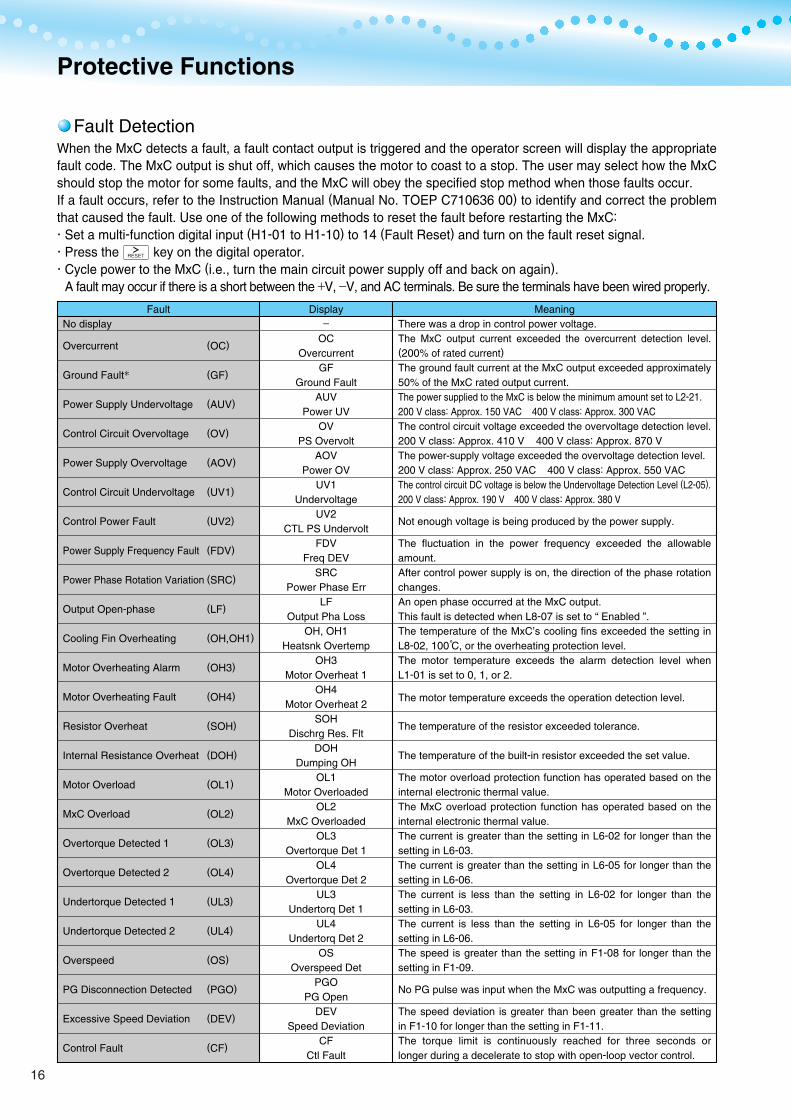
Fault DetectionWhen the MxC detects a fault, a fault contact output is triggered and the operator screen will display the appropriate fault code. The MxC output is shut off, which causes the motor to coast to a stop. The user may select how the MxC should stop the motor for some faults, and the MxC will obey the specified stop method when those faults occur.If a fault occurs, refer to the Instruction Manual (Manual No. TOEP C710636 00) to identify and correct the problem that caused the fault. Use one of the following methods to reset the fault before restarting the MxC: Set a multi-function digital input (H1-01 to H1-10) to 14 (Fault Reset) and turn on the fault reset signal. Press the key on the digital operator. Cycle power to the MxC (i.e., turn the main circuit power supply off and back on again). A fault may occur if there is a short between the +V, −V, and AC terminals. Be sure the terminals have been wired properly.
FaultNo display
Overcurrent
Ground Fault
Power Supply Undervoltage
Control Circuit Overvoltage
Power Supply Overvoltage
Control Circuit Undervoltage
Control Power Fault
Power Supply Frequency Fault
Power Phase Rotation Variation
Output Open-phase
Cooling Fin Overheating
Motor Overheating Alarm
Motor Overheating Fault
Resistor Overheat
Internal Resistance Overheat
Motor Overload
MxC Overload
Overtorque Detected 1
Overtorque Detected 2
Undertorque Detected 1
Undertorque Detected 2
Overspeed
PG Disconnection Detected
Excessive Speed Deviation
Control Fault
Display−
OCOvercurrent
GFGround Fault
AUVPower UV
OVPS Overvolt
AOVPower OV
UV1Undervoltage
UV2CTL PS Undervolt
FDVFreq DEV
SRCPower Phase Err
LFOutput Pha Loss
OH, OH1Heatsnk Overtemp
OH3Motor Overheat 1
OH4Motor Overheat 2
SOHDischrg Res. Flt
DOHDumping OH
OL1Motor Overloaded
OL2MxC Overloaded
OL3Overtorque Det 1
OL4Overtorque Det 2
UL3Undertorq Det 1
UL4Undertorq Det 2
OSOverspeed Det
PGOPG Open
DEVSpeed Deviation
CFCtl Fault
MeaningThere was a drop in control power voltage.The MxC output current exceeded the overcurrent detection level. (200% of rated current)
The ground fault current at the MxC output exceeded approximately 50% of the MxC rated output current.The power supplied to the MxC is below the minimum amount set to L2-21.200 V class: Approx. 150 VAC 400 V class: Approx. 300 VACThe control circuit voltage exceeded the overvoltage detection level.200 V class: Approx. 410 V 400 V class: Approx. 870 VThe power-supply voltage exceeded the overvoltage detection level.200 V class: Approx. 250 VAC 400 V class: Approx. 550 VACThe control circuit DC voltage is below the Undervoltage Detection Level (L2-05).200 V class: Approx. 190 V 400 V class: Approx. 380 V
Not enough voltage is being produced by the power supply.
The fluctuation in the power frequency exceeded the allowable amount.After control power supply is on, the direction of the phase rotation changes.An open phase occurred at the MxC output.This fault is detected when L8-07 is set to “ Enabled ”.The temperature of the MxC’s cooling fins exceeded the setting in L8-02, 100 C, or the overheating protection level.The motor temperature exceeds the alarm detection level when L1-01 is set to 0, 1, or 2.
The motor temperature exceeds the operation detection level.
The temperature of the resistor exceeded tolerance.
The temperature of the built-in resistor exceeded the set value.
The motor overload protection function has operated based on the internal electronic thermal value.The MxC overload protection function has operated based on the internal electronic thermal value.The current is greater than the setting in L6-02 for longer than the setting in L6-03.The current is greater than the setting in L6-05 for longer than the setting in L6-06.The current is less than the setting in L6-02 for longer than the setting in L6-03.The current is less than the setting in L6-05 for longer than the setting in L6-06.The speed is greater than the setting in F1-08 for longer than the setting in F1-09.
No PG pulse was input when the MxC was outputting a frequency.
The speed deviation is greater than been greater than the setting in F1-10 for longer than the setting in F1-11.The torque limit is continuously reached for three seconds or longer during a decelerate to stop with open-loop vector control.
(OC)
(GF)
(AUV)
(OV)
(AOV)
(UV1)
(UV2)
(FDV)
(SRC)
(LF)
(OH,OH1)
(OH3)
(OH4)
(SOH)
(DOH)
(OL1)
(OL2)
(OL3)
(OL4)
(UL3)
(UL4)
(OS)
(PGO)
(DEV)
(CF)
16
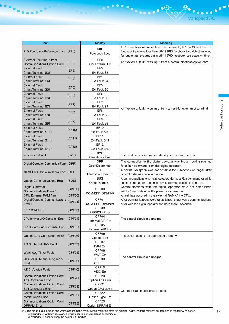
Varispeed AC
Fault
PID Feedback Reference Lost
External Fault Input from Communications Option CardExternal Fault(Input Terminal S3)
External Fault(Input Terminal S4)
External Fault(Input Terminal S5)
External Fault(Input Terminal S6)
External Fault(Input Terminal S7)
External Fault(Input Terminal S8)
External Fault(Input Terminal S9)
External Fault(Input Terminal S10)
External Fault(Input Terminal S11)
External Fault(Input Terminal S12)
Zero-servo Fault
Digital Operator Connection Fault
MEMOBUS Communications Error
Option Communications Error
Digital Operator Communications Error 1CPU External RAM FaultDigital Operator Communications Error 2
EEPROM Error
CPU Internal A/D Converter Error
CPU External A/D Converter Error
Option Card Connection Error
ASIC Internal RAM Fault
Watchdog Timer Fault
CPU-ASIC Mutual Diagnosis Fault
ASIC Version Fault
Communications Option Card A/D Converter ErrorCommunications Option Card Self Diagnostic ErrorCommunications Option Card Model Code ErrorCommunications Option Card DPRAM Error
Display
FBLFeedback Loss
EF0Opt External Flt
EF3Ext Fault S3
EF4Ext Fault S4
EF5Ext Fault S5
EF6Ext Fault S6
EF7Ext Fault S7
EF8Ext Fault S8
EF9Ext Fault S9
EF10Ext Fault S10
EF11Ext Fault S11
EF12Ext Fault S12
SVEZero Servo Fault
OPROper Disconnect
CEMemobus Com Err
BUSOption Com Err
CPF00COM-ERR(OP&INV)
CPF01COM-ERR(OP&INV)
CPF03EEPROM Error
CPF04Internal A/D Err
CPF05External A/D Err
CPF06Option error
CPF07RAM-ErrCPF08
WAT-ErrCPF09
CPU-ErrCPF10
ASIC-ErrCPF20
Option A/D errorCPF21
Option CPU downCPF22
Option Type ErrCPF23
Option DPRAM Err
MeaningA PID feedback reference loss was detected (b5-12 = 2) and the PID feedback input was less than b5-13 (PID feedback loss detection level) for longer than the time set in b5-14 (PID feedback loss detection time).
An “ external fault ” was input from a communications option card.
An “ external fault ” was input from a multi-function input terminal.
The rotation position moved during zero-servo operation.
The connection to the digital operator was broken during running for a Run command from the digital operator.A normal reception was not possible for 2 seconds or longer after control data was received once.A communications error was detected during a Run command or while setting a frequency reference from a communications option card.Communications with the digital operator were not established within 5 seconds after the power was turned on.A fault has occured in the external RAM of the CPU.After communications were established, there was a communications error with the digital operator for more than 2 seconds.
The control circuit is damaged.
The option card is not connected properly.
The control circuit is damaged.
Communications option card fault.
(FBL)
(EF0)
(EF3)
(EF4)
(EF5)
(EF6)
(EF7)
(EF8)
(EF9)
(EF10)
(EF11)
(EF12)
(SVE)
(OPR)
(CE)
(BUS)
(CPF00)
(CPF00)
(CPF01)
(CPF03)
(CPF04)
(CPF05)
(CPF06)
(CPF07)
(CPF08)
(CPF09)
(CPF10)
(CPF20)
(CPF21)
(CPF22)
(CPF23)
: The ground fault here is one which occurs in the motor wiring while the motor is running. A ground fault may not be detected in the following cases. A ground fault with low resistance which occurs in motor cables or terminals. A ground fault occurs when the power is turned on.
17
Pro
tect
ive
Fun
ctio
ns

Protective Functions (Cont’d)
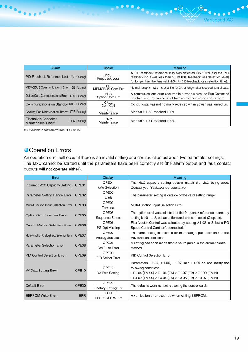
Alarm DetectionAlarms are detected as a type of MxC protection function that do not operate the fault contact output. The system will automatically return to its original status once the cause of the alarm has been removed.The digital operator display flashes and the alarm is output from the multi-function outputs.
Alarm
Forward/Reverse Run Commands Input Together
Control Circuit Undervoltage
Power Supply Undervoltage
Power Supply Frequency Fault
Power Supply Undervoltage
Power Phase Rotation Variation
Control Circuit Overvoltage
Cooling Fin Overheating
MxC Overheating Pre-alarm
Motor Overheating
Internal Resistance Overheat
Overtorque 1
Overtorque 2
Undertorque 1
Undertorque 2
Overspeed
The PG is Disconnected
Excessive Speed Deviation
External Fault Detected forCommunications Card
External Fault (Input Terminal S3)
External Fault (Input Terminal S4)
External Fault (Input Terminal S5)
External Fault (Input Terminal S6)
External Fault (Input Terminal S7)
External Fault (Input Terminal S8)
External Fault (Input Terminal S9)
External Fault (Input Terminal S10)
External Fault (Input Terminal S11)
External Fault (Input Terminal S12)
Display EF
External Fault
UV
PS Undervolt
AUV Power UV
FDV Freq DEV
FDVFreq DEV
SRC Power Phase Err
OV PS Overvolt
OH Heatsink Overtemp
OH2 Over Heat 2
OH3 Motor Overheat 1
DOH Dumping OH
OL3 Overtorque Det 1
OL4 Overtorque Det 2
UL3
Undertorq Det 1
UL4 Undertorq Det 2
OS Overspeed Det
PGO PG Open
DEV Speed Deviation
EF0Opt External Flt
EF3 Ext Fault S3
EF4 Ext Fault S4
EF5 Ext Fault S5
EF6 Ext Fault S6
EF7 Ext Fault S7
EF8 Ext Fault S8
EF9 Ext Fault S9
EF10 Ext Fault S10
EF11 Ext Fault S11
EF12 Ext Fault S12
Meaning Both the Forward and Reverse Run Commands have been on for more than 0.5 s.
The following conditions occurred when there was no run signal. The control circuit voltage was below the undervoltage detection level setting (L2-05). The control power supply voltage was below the CUV level.
The power supply is below the undervoltage detection level (L2-21).200 V class: Approx. 150 VAC 400 V class: Approx. 300 VAC The fluctuation in the power frequency exceeded the allowable amount.
The power supply is below the undervoltage detection level (L2-21).200 V class: Approx. 150 VAC 400 V class: Approx. 300 VAC After control power supply is on, the direction of the phase rotation changes.
The control circuit voltage exceeded the overvoltage detection level.200 V class: Approx. 410 V 400 V class: Approx. 870 V The temperature of the MxC’s cooling fins exceeded the setting in L8-02. An OH2 alarm signal (MxC overheating alarm signal) was input from a multi-function input terminal (S3 to S12). The MxC continues or stops the operation according to the setting of L1-03. The temperature of the built-in resistor exceeded the set value. The current is greater than the setting in L6-02 for longer than the setting in L6-03. The current is greater than the setting in L6-05 for longer than the setting in L6-06. The current is less than the setting in L6-02 for longer than the setting in L6-03. The current is less than the setting in L6-05 for longer than the setting in L6-06. The speed is greater than the setting in F1-08 for longer than the setting in F1-09. The MxC is outputting a frequency, but no PG pulse is being input. The speed deviation is greater than the setting in F1-10 for longer than the setting in F1-11.
Continuing operation was specified for EF0 (F6-03=3) and an external fault was input from the option card.
An external fault was input from a multi-function input terminal.
EF (Flashing)
UV (Flashing)
AUV (Flashing)
FDV (Flashing)
FDV (Flashing)
SRC (Flashing)
OV (Flashing)
OH (Flashing)
OH2 (Flashing)
OH3 (Flashing)
DOH (Flashing)
OL3 (Flashing)
OL4 (Flashing)
UL3 (Flashing)
UL4 (Flashing)
OS (Flashing)
PGO (Flashing)
DEV (Flashing)
EF0 (Flashing)
EF3 (Flashing)
EF4 (Flashing)
EF5 (Flashing)
EF6 (Flashing)
EF7 (Flashing)
EF8 (Flashing)
EF9 (Flashing)
EF10 (Flashing)
EF11 (Flashing)
EF12 (Flashing)
18
Varispeed AC
Operation ErrorsAn operation error will occur if there is an invalid setting or a contradiction between two parameter settings.The MxC cannot be started until the parameters have been correctly set (the alarm output and fault contact outputs will not operate either).
Error
Incorrect MxC Capacity Setting
Parameter Setting Range Error
Multi-Function Input Selection Error
Option Card Selection Error
Control Method Selection Error
Multi-Function Analog Input Selection Error
Parameter Selection Error
PID Control Selection Error
V/f Data Setting Error
Default Error
EEPROM Write Error
Display
OPE01
kVA Selection
OPE02
Limit
OPE03
Terminal
OPE05
Sequence Select
OPE06
PG Opt Missing
OPE07
Analog Selection
OPE08
Ctrl Func Error
OPE09
PID Select Error
OPE10
V/f Ptrn Setting
OPE20
Factory Setting Err
ERR
EEPROM R/W Err
Meaning
The MxC capacity setting doesn't match the MxC being used.
Contact your Yaskawa representative.
The parameter setting is outside of the valid setting range.
Multi-Function Input Selection Error
The option card was selected as the frequency reference source by
setting b1-01 to 3, but an option card isn't connected (C option).
Flux Vector Control was selected by setting A1-02 to 3, but a PG
Speed Control Card isn’t connected.
The same setting is selected for the analog input selection and the
PID function selection.
A setting has been made that is not required in the current control
method.
PID Control Selection Error
Parameters E1-04, E1-06, E1-07, and E1-09 do not satisfy the
following conditions:
E1-04 (FMAX) ≥ E1-06 (FA) > E1-07 (FB) ≥ E1-09 (FMIN)
E3-02 (FMAX) ≥ E3-04 (FA) > E3-05 (FB) ≥ E3-07 (FMIN)
The defaults were not set replacing the control card.
A verification error occurred when writing EEPROM.
OPE01
OPE02
OPE03
OPE05
OPE06
OPE07
OPE08
OPE09
OPE10
OPE20
ERR
Alarm
PID Feedback Reference Lost
MEMOBUS Communications Error
Option Card Communications Error
Communications on Standby
Cooling Fan Maintenance Timer
Electrolytic Capacitor Maintenance Timer
Display
FBLFeedback Loss
CEMEMOBUS Com Err
BUSOption Com Err
CALLCom Call
LT-FMaintenance
LT-CMaintenance
Meaning
A PID feedback reference loss was detected (b5-12=2) and the PID feedback input was less than b5-13 (PID feedback loss detection level) for longer than the time set in b5-14 (PID feedback loss detection time).
Normal reception was not possible for 2 s or longer after received control data.
A communications error occurred in a mode where the Run Command or a frequency reference is set from an communications option card.
Control data was not normally received when power was turned on.
Monitor U1-63 reached 100%.
Monitor U1-61 reached 100%.
FBL (Flashing)
CE (Flashing)
BUS (Flashing)
CALL (Flashing)
LT-F (Flashing)
LT-C (Flashing)
: Available in software version PRG: S1050.
19
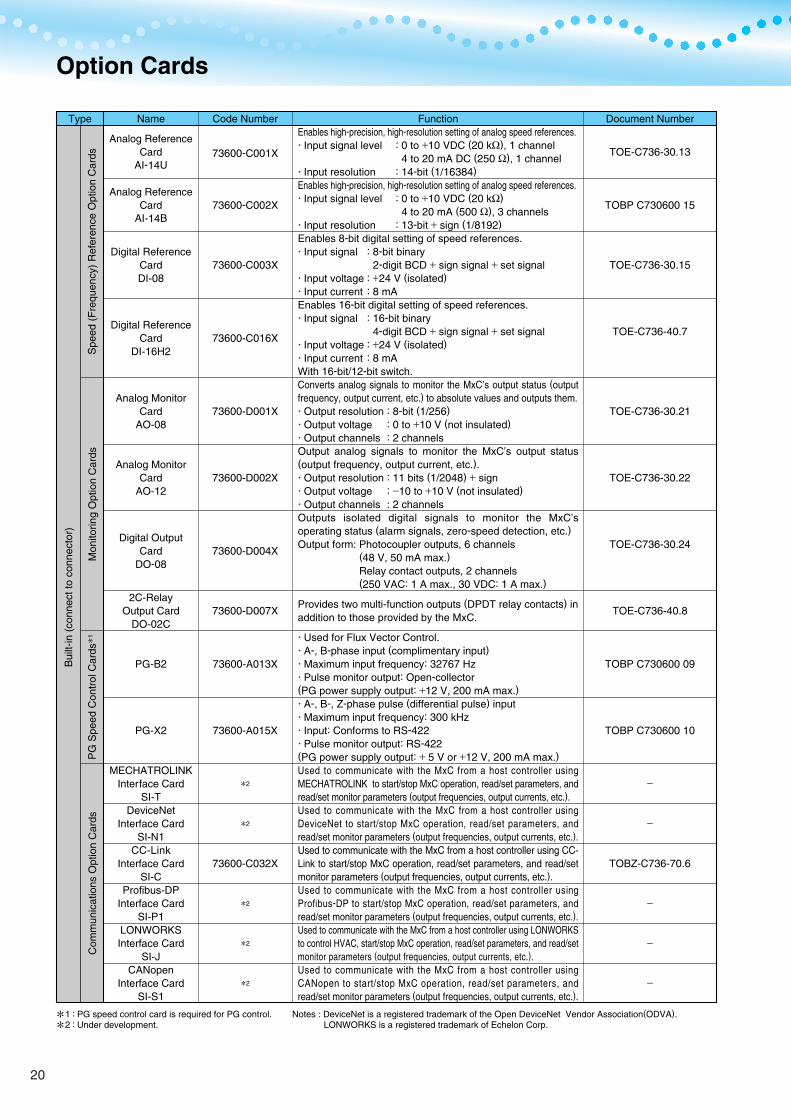
Option Cards
Type Name Code Number Document NumberFunction
Analog Reference Card
AI-14U
Analog Reference Card
AI-14B
Digital ReferenceCardDI-08
Digital ReferenceCard
DI-16H2
Analog MonitorCard
AO-08
Analog MonitorCard
AO-12
Digital OutputCard
DO-08
2C-RelayOutput Card
DO-02C
PG-B2
PG-X2
MECHATROLINK Interface Card
SI-TDeviceNet
Interface CardSI-N1
CC-Link Interface Card
SI-CProfibus-DP
Interface CardSI-P1
LONWORKS Interface Card
SI-JCANopen
Interface CardSI-S1
73600-C001X
73600-C002X
73600-C003X
73600-C016X
73600-D001X
73600-D002X
73600-D004X
73600-D007X
73600-A013X
73600-A015X
2
2
73600-C032X
2
2
2
Enables high-precision, high-resolution setting of analog speed references. Input signal level : 0 to +10 VDC (20 kΩ), 1 channel
4 to 20 mA DC (250 Ω), 1 channel Input resolution : 14-bit (1/16384)Enables high-precision, high-resolution setting of analog speed references. Input signal level : 0 to +10 VDC (20 kΩ)
4 to 20 mA (500 Ω), 3 channels Input resolution : 13-bit + sign (1/8192)Enables 8-bit digital setting of speed references. Input signal : 8-bit binary
2-digit BCD + sign signal + set signal Input voltage : +24 V (isolated) Input current : 8 mAEnables 16-bit digital setting of speed references. Input signal : 16-bit binary
4-digit BCD + sign signal + set signal Input voltage : +24 V (isolated) Input current : 8 mAWith 16-bit/12-bit switch.Converts analog signals to monitor the MxC’s output status (output frequency, output current, etc.) to absolute values and outputs them. Output resolution : 8-bit (1/256) Output voltage : 0 to +10 V (not insulated) Output channels : 2 channelsOutput analog signals to monitor the MxC’s output status (output frequency, output current, etc.). Output resolution : 11 bits (1/2048) + sign Output voltage : −10 to +10 V (not insulated) Output channels : 2 channelsOutputs isolated digital signals to monitor the MxC’s operating status (alarm signals, zero-speed detection, etc.)Output form: Photocoupler outputs, 6 channels
(48 V, 50 mA max.)Relay contact outputs, 2 channels(250 VAC: 1 A max., 30 VDC: 1 A max.)
Provides two multi-function outputs (DPDT relay contacts) inaddition to those provided by the MxC.
Used for Flux Vector Control. A-, B-phase input (complimentary input) Maximum input frequency: 32767 Hz Pulse monitor output: Open-collector(PG power supply output: +12 V, 200 mA max.) A-, B-, Z-phase pulse (differential pulse) input Maximum input frequency: 300 kHz Input: Conforms to RS-422 Pulse monitor output: RS-422(PG power supply output: + 5 V or +12 V, 200 mA max.)Used to communicate with the MxC from a host controller using MECHATROLINK to start/stop MxC operation, read/set parameters, and read/set monitor parameters (output frequencies, output currents, etc.).Used to communicate with the MxC from a host controller using DeviceNet to start/stop MxC operation, read/set parameters, and read/set monitor parameters (output frequencies, output currents, etc.).Used to communicate with the MxC from a host controller using CC-Link to start/stop MxC operation, read/set parameters, and read/set monitor parameters (output frequencies, output currents, etc.).Used to communicate with the MxC from a host controller using Profibus-DP to start/stop MxC operation, read/set parameters, and read/set monitor parameters (output frequencies, output currents, etc.). Used to communicate with the MxC from a host controller using LONWORKS to control HVAC, start/stop MxC operation, read/set parameters, and read/set monitor parameters (output frequencies, output currents, etc.). Used to communicate with the MxC from a host controller using CANopen to start/stop MxC operation, read/set parameters, and read/set monitor parameters (output frequencies, output currents, etc.).
TOE-C736-30.13
TOBP C730600 15
TOE-C736-30.15
TOE-C736-40.7
TOE-C736-30.21
TOE-C736-30.22
TOE-C736-30.24
TOE-C736-40.8
TOBP C730600 09
TOBP C730600 10
−
−
TOBZ-C736-70.6
−
−
−
12
::PG speed control card is required for PG control. Under development.
Com
mun
icat
ions
Opt
ion
Car
dsP
G S
peed
Con
trol
Car
ds
1S
peed
(F
requ
ency
) R
efer
ence
Opt
ion
Car
dsM
onito
ring
Opt
ion
Car
ds
Bui
lt-in
(co
nnec
t to
conn
ecto
r)
Notes : DeviceNet is a registered trademark of the Open DeviceNet Vendor Association(ODVA). LONWORKS is a registered trademark of Echelon Corp.
20

Varispeed ACPeripheral Devices
Protects the MxC
wiring
Prevents burning
of the MxC
Contains
switching surge
Isolates I/O signals
Reduces the
effects of radio
and
control device
noise
Operates the MxC
externally
Controls the MxC
system
Saves the
momentary power
loss compensation
time of the MxC
Sets/monitors
frequencies sand
voltages externally
Corrects frequency
reference input,
frequency meter,
ammeter scales
MCCB or Earth
Leakage Breaker
Magnetic
Contactor
Surge Suppressor
Isolator
Input Noise
Filter
Finemet
Zero-Phase
Reactor to Reduce
Radio Noise
Output Noise
Filter
VS Operator
(Small Plastic
Operator)
VS Operator
(Standard Steel-
Plate Operator)
Digital Operator
Extension Cable
VS System
Module
Back-up
Capacitor Unit
for Momentary
Power Loss
Frequency Meter
Frequency Setting
Potentiometer
Frequency
Setting Knob
Output Voltmeter
Potentiometer for
Frequency Reference
Frequency Meter
Adjusting Potentiometer
NF
SC series
DCR2-
DGP
LNFD-
FN-
F6045GB(FIL001098)
F11080GB(FIL001097)
LF-
JVOP-95
(73041-0905X- )
JVOP-96
(73041-0906X- )
1 m cable:(WV001)
3 m cable:(WV003)
JGSM-
P00 0
(73600-P00 0)
DCF-6A
RV30YN20S 2kΩ(RH000739)
CM-3S
SCF-12NH
2 kΩ (ETX003270)
20 kΩ (ETX003120)
RV30YN20S 20 kΩ(RH000850)
Always connect a breaker to the power supply
line to protect the MxC wiring.
Install to prevent the MxC from burning out when
faults occur at the input terminal side of the MxC.
Always attach a surge absorber to the coil.
Absorbs surge from the magnetic contactor and
control relays. Connect surge suppressors to all
magnetic contactors and relays near the MxC.
Isolates the I/O signals of the MxC and
is enabled against inductive noise.
Reduces noise coming into the MxC from the power
supply line and noise flowing from the MxC into the power
supply line. Connect as close to the MxC as possible.
Reduces noise coming into the MxC from the power
supply line and noise flowing from the MxC into the
power supply line. Insert as close to the MxC as possible.
Can be used on both the input and output sides.
Reduces noise generated by the MxC.
Connect as close to the MxC as possible.Allows frequency reference settings and ON/OFF operation control to be performed by analog references from a remote location (50 m max).Frequency counter specifications: 60/120 Hz, 90/180HzAllows frequency reference settings and ON/OFF operation control to be performed by analog references from a remote location (50 m max)Frequency counter specifications: 75 Hz, 150 Hz, 220 Hz
Extension cable to use a digital operator remotely.
Cable length: 1 m or 3 m
A system controller that can be matched
to the automatic control system to produce
an optimum system configuration.
Document No. : TSE-C730-30
Safety measure taken to protect
against momentary power loss of the
control power supply.
Document No. : TOE-C736-50.6
Devices to set or monitor frequencies
externally.
Devices to measure the output voltage
externally.
Connected to the control circuit terminals
to input a frequency reference.
Calibrates the scale of frequency meters
and ammeters.
P22
P22
P22
P28
P23
P26
P25
−
−
P26
−
P28
P27
P27
P27
P27
: Use an earth leakage breaker which has harmonics protection and a minimum current of 30 mA per MxC. Otherwise, the harmonic leakage current may cause a malfunction. If a malfunction occurs in an earth leakage breaker without harmonic protection, lower the carrier frequency of the MxC, replace the earth leakage breaker with one that has harmonic protection, or raise the current of the earth leakage breaker to 200 mA or more per MxC.(Example) Mitsubishi Electric Corporation NV series (those produced after 1988)
Fuji Electric FA Components & Systems Co., Ltd. EG, SG series (those produced after 1984)
MxC
PowerSupply
Molded-CaseCircuit Breakeror EarthLeakage Breaker
MagneticContactor(MC)
Input NoiseFilter
Grounding
Grounding
Output NoiseFilter
Motor
Zero-PhaseReactor
Zero-PhaseReactor
Purpose Model (Code) DescriptionsName Ref.Page
21
Opt
ion
Car
ds/P
erip
hera
lDev
ices
Lead 250
Lead 910
Details of MountingHole Dimensions 2-3 Tap
2-4 Dia.Mounting Holes
0.8 Dia.4.8 Dia.
18 Dia.30
24 16
36
7
6
22.5
30 16
34
68
76
2633
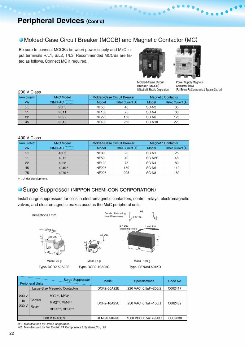
Type: DCR2-50A22E Type: DCR2-10A25C Type: RFN3AL504KD
Mass : 22 g Mass : 5 g Mass : 150 g
Dimentions : mm
Molded-Case Circuit Breaker (MCCB) and Magnetic Contactor (MC)
Peripheral Devices (Cont’d)
Surge Suppressor (NIPPON CHEMI-CON CORPORATION)
Be sure to connect MCCBs between power supply and MxC in-put terminals R/L1, S/L2, T/L3. Recommended MCCBs are lis-ted as follows. Connect MC if required.
Molded-Case CircuitBreaker (MCCB)[Mitsubishi Electric Corporation]
Power Supply MagneticContactor (MC)[Fuji Electric FA Components & Systems Co., Ltd]
Install surge suppressors for coils in electromagnetic contactors, control relays, electromagnetic valves, and electromagnetic brakes used as the MxC peripheral units.
200 V
to
230 V
Peripheral UnitsSurge Suppressor
Control
Relay
Model
DCR2-50A22E
DCR2-10A25C
RFN3AL504KD
Specifications
220 VAC, 0.5 F+200Ω
250 VAC, 0.1 F+100Ω
1000 VDC, 0.5 F+220Ω
Code No.
C002417
C002482
C002630
MY21, MY31
MM21, MM41
HH222, HH232
Large-Size Magnetic Contactors
380 V to 460 V
Motor Capacity
kW
5.5
11
22
45
75
Model
NF30
NF50
NF100
NF225
NF225
Rated Current (A)
20
40
75
150
225
Model
SC-N1
SC-N2S
SC-N4
SC-N6
SC-N8
Rated Current (A)
25
48
80
110
180
400 V ClassMagnetic Contactor
Motor Capacity
kW
5.5
11
22
45
Model
NF50
NF100
NF225
NF400
Rated Current (A)
40
75
150
250
Model
SC-N2
SC-N4
SC-N6
SC-N10
Rated Current (A)
35
80
125
220
200 V ClassMolded-Case Circuit Breaker Magnetic Contactor
: Under development.
Molded-Case Circuit Breaker
MxC Model
CIMR-AC
25P5
2011
2022
2045
MxC Model
CIMR-AC
45P5
4011
4022
4045
4075
µ
µ
µ
Manufactured by Omron Corporation.Manufactured by Fuji Electric FA Components & Systems Co., Ltd.
::
12
22
Varispeed AC
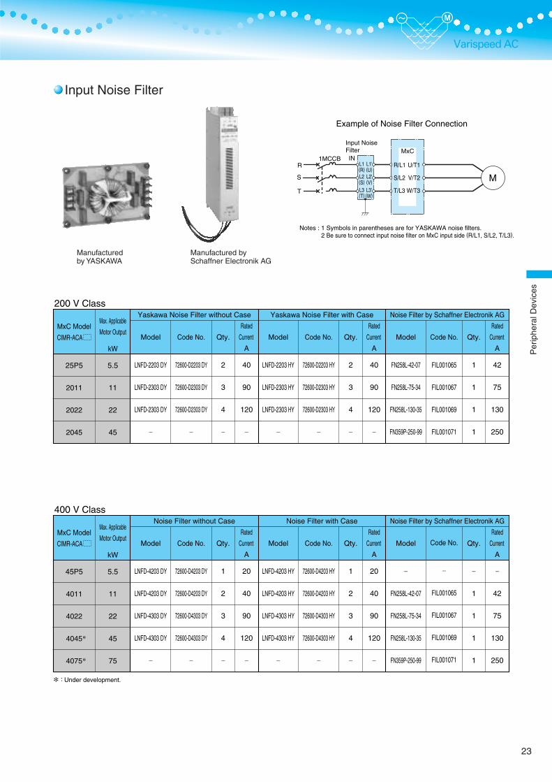
Input Noise Filter
Manufacturedby YASKAWA
Manufactured bySchaffner Electronik AG
MxCInput NoiseFilterIN
R/L1
S/L2
T/L3
U/T1
V/T2
W/T3
L1(R)L2(S)L3(T)
L1'(U)L2'(V)L3'(W)
M
Notes : 1 Symbols in parentheses are for YASKAWA noise filters. 2 Be sure to connect input noise filter on MxC input side (R/L1, S/L2, T/L3).
Example of Noise Filter Connection
R
S
T
1MCCB
Max. Applicable
Motor Output
kW
5.5
11
22
45
75
400 V Class
Model
LNFD-4203 DY
LNFD-4203 DY
LNFD-4303 DY
LNFD-4303 DY
−
Code No.
72600-D4203 DY
72600-D4203 DY
72600-D4303 DY
72600-D4303 DY
−
Qty.
1
2
3
4
−
Rated
Current
A
20
40
90
120
−
Noise Filter without Case
Model
LNFD-4203 HY
LNFD-4203 HY
LNFD-4303 HY
LNFD-4303 HY
−
Code No.
72600-D4203 HY
72600-D4203 HY
72600-D4303 HY
72600-D4303 HY
−
Qty.
1
2
3
4
−
Rated
Current
A
20
40
90
120
−
Noise Filter with Case
Model
−
FN258L-42-07
FN258L-75-34
FN258L-130-35
FN359P-250-99
Code No.
−
FIL001065
FIL001067
FIL001069
FIL001071
Qty.
−
1
1
1
1
Rated
Current
A
−
42
75
130
250
Noise Filter by Schaffner Electronik AG
:
MxC Model
CIMR-ACA
45P5
4011
4022
4045
4075
Max. Applicable
Motor Output
kW
5.5
11
22
45
200 V Class
Model
LNFD-2203 DY
LNFD-2303 DY
LNFD-2303 DY
−
Code No.
72600-D2203 DY
72600-D2303 DY
72600-D2303 DY
−
Qty.
2
3
4
−
Rated
Current
A
40
90
120
−
Yaskawa Noise Filter without Case
Model
LNFD-2203 HY
LNFD-2303 HY
LNFD-2303 HY
−
Code No.
72600-D2203 HY
72600-D2303 HY
72600-D2303 HY
−
Qty.
2
3
4
−
Rated
Current
A
40
90
120
−
Yaskawa Noise Filter with Case
Model
FN258L-42-07
FN258L-75-34
FN258L-130-35
FN359P-250-99
Code No.
FIL001065
FIL001067
FIL001069
FIL001071
Qty.
1
1
1
1
Rated
Current
A
42
75
130
250
Noise Filter by Schaffner Electronik AG
MxC Model
CIMR-ACA
25P5
2011
2022
2045
Under development.
23
Per
iphe
ralD
evic
es

Drawing 1 Drawing 2Note: The drawing shows when using a noise filter for 3-phase power supply.
Detail of TerminalStation
Detail ofTerminalStation
Detail of Mounting Hole
U
V
W
E
W ±1.5
A ±1
W ±1.5
5 Dia.
30 D
ia.
A´ ±1 A´ ±1
H M
ax.
B ±1
D ±1
.5
B ±1
D ±1
.5RS
T
U
V
W
E
RS
T
H M
ax.
W
B D
C
C
H(M
ax.)
A
Drawing 1 Drawing 2 Drawing 3
Mounting Screws Mounting Screws
Mounting Screw
12 D
ia.
(Note)
Model
LNFD-
2203DY
2303DY
4203DY
4303DY
Code No.
72600-
D2203DY
D2303DY
D4203DY
D4303DY
Noise Filter Terminal
W
170
170
200
200
D
90
110
145
145
H
70
70
100
100
B
78
98
133
133
M
20
20
30
30
X
9
10
9
10
Y
11
13
11
13
Mass
kg
0.4
0.5
0.5
0.6
A(A')
158(79)
(94)
(94)
DWG
1
2
2
2
Model
LNFD-
2203HY
2303HY
4203HY
4303HY
Code No.
72600-
D2203HY
D2303HY
D4203HY
D4303HY
Noise Filter Terminal
W
240
240
270
270
D
125
125
155
155
H
100
100
125
125
B
95
95
125
125
C
33
33
43
43
X
9
10
9
10
Y
11
13
11
13
Mass
kg
1.5
1.6
2.2
2.2
A
210
210
240
240
Model
FN258L-42-07
FN258L-75-34
FN258L-130-35
FN359P-250-99
A
329
329
439±1.5
See dimensions in the drawing.
B
185±1
220
240
C
70
80
110±0.8
D
300
300
400±1.2
E
314
314
414
F
45
55
80
G
6.5
6.5
6.5
H
500−−
J
1.5
1.5
3
L
12−−
O
M6
M6
M10
P
AWG8−−
Mass kg
2.8
4.0
7.5
16
DWG
1
2
2
3
Manufactured by Schaffner Electronik AG
DimensionsWith CaseWithout Case
Units : mm
Units : mm
Input Noise Filter (Cont’d)
Peripheral Devices (Cont’d)
24
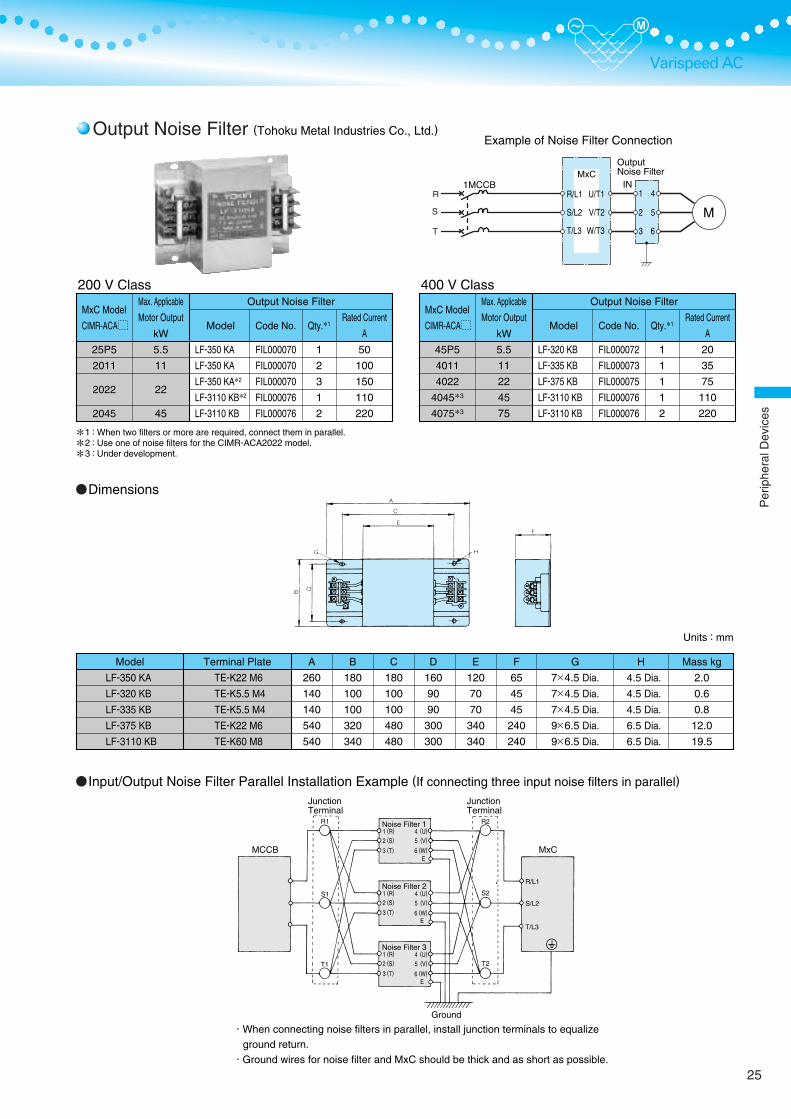
Varispeed AC
MxCOutputNoise Filter
INR/L1
S/L2
T/L3
U/T1
V/T2
W/T3
1
2
3
4
5
6
Example of Noise Filter Connection
When connecting noise filters in parallel, install junction terminals to equalizeground return.
Ground wires for noise filter and MxC should be thick and as short as possible.
MCCB
R1
Ground
R2
S2
T2
S1
T1
R/L1
S/L2
T/L3
Noise Filter 11 (R)
2 (S)
3 (T)
4 (U)
5 (V)
6 (W)
4 (U)
5 (V)
6 (W)
4 (U)
5 (V)
6 (W)
E
Noise Filter 21 (R)
2 (S)
3 (T)E
Noise Filter 31 (R)
2 (S)
3 (T)E
MxC
R
S
T
1MCCB
Units : mm
Model
LF-350 KA
LF-320 KB
LF-335 KB
LF-375 KB
LF-3110 KB
Terminal Plate
TE-K22 M6
TE-K5.5 M4
TE-K5.5 M4
TE-K22 M6
TE-K60 M8
A
260
140
140
540
540
B
180
100
100
320
340
C
180
100
100
480
480
D
160
90
90
300
300
E
120
70
70
340
340
F
65
45
45
240
240
G
7×4.5 Dia.
7×4.5 Dia.
7×4.5 Dia.
9×6.5 Dia.
9×6.5 Dia.
H
4.5 Dia.
4.5 Dia.
4.5 Dia.
6.5 Dia.
6.5 Dia.
Mass kg
2.0
0.6
0.8
12.0
19.5
Dimensions
Input/Output Noise Filter Parallel Installation Example (If connecting three input noise filters in parallel)
M
MxC Model
CIMR-ACA
25P5
2011
2022
2045
Max. Applicable
Motor Output
kW
5.5
11
22
45
200 V Class
Model
LF-350 KA
LF-350 KA
LF-350 KA2
LF-3110 KB2
LF-3110 KB
Code No.
FIL000070
FIL000070
FIL000070
FIL000076
FIL000076
Qty.1
1
2
3
1
2
Rated Current
A
50
100
150
110
220
Output Noise Filter
123
:::
When two filters or more are required, connect them in parallel.Use one of noise filters for the CIMR-ACA2022 model.Under development.
MxC Model
CIMR-ACA
45P5
4011
4022
40453
40753
Max. Applicable
Motor Output
kW
5.5
11
22
45
75
400 V Class
Model
LF-320 KB
LF-335 KB
LF-375 KB
LF-3110 KB
LF-3110 KB
Code No.
FIL000072
FIL000073
FIL000075
FIL000076
FIL000076
Qty.1
1
1
1
1
2
Rated Current
A
20
35
75
110
220
Output Noise Filter
JunctionTerminal
JunctionTerminal
Output Noise Filter (Tohoku Metal Industries Co., Ltd.)
25
Per
iphe
ralD
evic
es
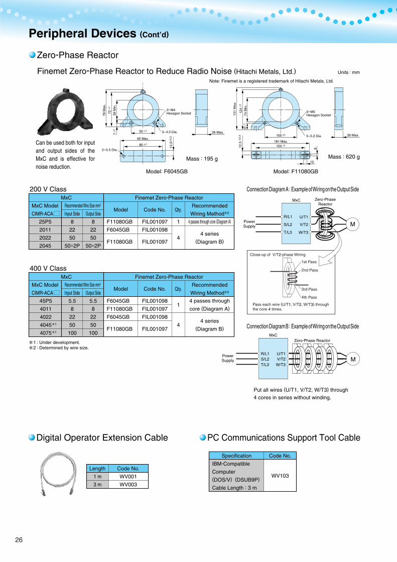
Peripheral Devices (Cont’d)
Zero-Phase Reactor
Digital Operator Extension Cable PC Communications Support Tool Cable
Finemet Zero-Phase Reactor to Reduce Radio Noise (Hitachi Metals, Ltd.)Note: Finemet is a registered trademark of Hitachi Metals, Ltd.
Put all wires (U/T1, V/T2, W/T3) through 4 cores in series without winding.
78 M
ax.
131 M
ax.
74 M
in.
39 M
in.
72 ±
1
124
±112
.5 ±
0.3
20 ±
1
7 ±1 50 ±1
95 Max.
80 ±1
12.5
±0.3
3-4.5 Dia.3-5.2 Dia.
2-5.5 Dia.
26 Max.26 Max.100 ±1
181 Max.150 ±1
3-M4Hexagon Socket
Mass : 195 g Mass : 620 g
3-M5Hexagon Socket
Model: F6045GB Model: F11080GB
8
12
Can be used both for input and output sides of the MxC and is effective for noise reduction.
M
Connection Diagram B : Example of Wiring on the Output Side
PowerSupply
MxC
U/T1V/T2W/T3
R/L1S/L2T/L3
Zero-Phase Reactor
Connection Diagram A : Example of Wiring on the Output Side
R/L1
S/L2
T/L3
U/T1
MxC
V/T2
W/T3
M
Close-up of V/T2-phase Wiring
Pass each wire (U/T1, V/T2, W/T3) throughthe core 4 times.
1st Pass
2nd Pass
3rd Pass
4th Pass
Units : mm
MxC Model
CIMR-ACA
25P5
2011
2022
2045
MxC
Recommended Wire Size mm2
Input Side
8
22
50
50×2P
Output Side
8
22
50
50×2P
200 V Class
Model
F11080GB
F6045GB
F11080GB
Code No.
FIL001097
FIL001098
FIL001097
Qty.
1
4
Recommended
Wiring Method2
4 passes through core (Diagram A)
4 series(Diagram B)
Finemet Zero-Phase Reactor
Input Side
5.5
8
22
50
100
MxC Model
CIMR-ACA
1
1
MxC
Recommended Wire Size mm2
Output Side
5.5
8
22
50
100
400 V Class
Model
F6045GB
F11080GB
F6045GB
F11080GB
Code No.
FIL001098
FIL001097
FIL001098
FIL001097
Qty.
1
4
Recommended
Wiring Method2
4 passes through
core (Diagram A)
4 series(Diagram B)
Finemet Zero-Phase Reactor
12
::Under development.Determined by wire size.
Length
1 m
3 m
Code No.
WV001
WV003
Specification
IBM-Compatible
Computer(DOS/V) (DSUB9P)
Cable Length : 3 m
Code No.
WV103
45P5
4011
4022
4045
4075
PowerSupply
Zero-PhaseReactor
26
Varispeed AC
4-5 Dia.
4-4 Dia.
Shaft 6 Dia.
Note : Attach to MxC terminal.
30
Dia
.
6 D
ia.
2.8 Dia.
Frequency Meter/Ammeter 1 mA Full-Scale [Model : DCF-6A*, 3 V ]
Frequency Setting Potentiometer [Model : RV30YN20S, 2kΩ (Code No. RH 000739)]
Output Voltmeter Rectification Type Class 2.5 [Model : SCF-12NH]
Frequency Meter Adjusting Potentiometer [Model : RV30YN20S, 20 kΩ (Code No. RH 000850)]
Potentiometer(Code No. NPJT41561-1)Scale PlateFrequency Setting Knob
[Model : CM-3S]2 kΩ for frequencyreference control(Code No. EXT003270)20 kΩ for scale adjusting(Code No. EXT003120)
Mass : 300 g
Mass : 20 g
Panel Drilling Plan
Units : mm
Mass : 200 gPanel Drilling Plan
Units : mm
Units : mm
Mass : 300 gPanel Drilling Plan
Units : mm
Units : mm
200 V Class : 300 V Full-scale400 V Class : 600 V Full-scale
[ Output Voltmeter : Code No. VM000481]
Output Voltmeter : Code No. VM000502
Transformer for Instrument : Code No. PT000084
DCF-6A is 3 V, 1 mA, 3 kΩ. For MxC multi-function analog monitor output, set frequency meter adjusting potentiometer (20 kΩ) or parameter H4-02, -05 (analog monitor output gain) within the range of 0 to 3 V (initial setting is 0 to 10 V).
*:
2-M4 Terminal Screws4-M3 Mounting Bolts
Note : For scale of ammeter, contact your YASKAWA representative.
2-M4 Terminal Screws
4-M4 Mounting Bolts
85 D
ia.
3.6 Dia.
9.5 Dia.
52 D
ia.
30
4.5 Dia.
10 Dia.
Per
iphe
ralD
evic
es
27
RS
T
Isolator (Insulation Type DC Transmission Converter)Performance
4 to 20 mA : Within 100 m 0 to 10 V : Within 50 m
Mass : 2 kg
Approx. Mass : 60 g
(1)
(2)
(3)
(4)
Use this unit to extend the MxC’s power loss ride-thru ability to 2 seconds.200 V Class [P0010] (Code No.: 73600-P0010)400 V Class [P0020] (Code No.: 73600-P0020)
(5)(6)
(7)
(8)
Allowance
TemperatureInfluenceAux. PowerSupply InfluenceLoad ResistanceInfluence
Output RippleResponse Time
WithstandVoltage
InsulationResistance
±0.25 % of output span(Ambient temp.: 23 C)With ±0.25 % of output span(The value at ±10 C of ambient temp.)With ±0.1 % of output span(The value at ±10 % of aux. power supply)With ±0.05 % of output span(In the range of load resistance)
With 0.5 % peak to peak of output span0.5 s or less (Time to settle to ±1 % of final steady value)2000 VAC for one min.(between each terminal of input, output, power supply, and enclosure)20 MΩ and above (by 500 VDC megger)(between each terminal of input, output, power supply, and enclosure)
Approx. Mass : 350 g
Isolator
Socket View of Socket Mounting
:Potentiometer’s adjuster position varies according to the model.
Back-up Capacitor Unit for Momentary Power Loss
N B1/PE
Motor
M
R/L1
S/L2
T/L3
U/T1V/T2
W/T3
p1n1
90
300
280
9650
4-M6 Mounting Screws
Terminal12345678
DescriptionOutput +Output −
−Input +Input −GroundPowerSupply
: If this unit is not used, the MxC can ride thru a power loss for 0.5 to 2 seconds, depending on the MxC’s capacity and operating conditions.
MCCB
Model
DGP2-4-4
DGP2-4-8
DGP2-8-4
DGP2-3-4
DGP3-4-4
DGP3-4-8
DGP3-8-4
DGP3-3-4
Input Signal
0 to 10 V
0 to 10 V
4 to 20 mA
0 to 5 V
0 to 10 V
0 to 10 V
4 to 20 mA
0 to 5 V
Output Signal
0 to 10 V
4 to 20 mA
0 to 10 V
0 to 10 V
0 to 10 V
4 to 20 mA
0 to 10 V
0 to 10 V
Power Supply
100 VAC
100 VAC
100 VAC
100 VAC
200 VAC
200 VAC
200 VAC
200 VAC
Code No.
CON 000019.25
CON 000019.26
CON 000019.35
CON 000019.15
CON 000020.25
CON 000020.26
CON 000020.35
CON 000020.15
Product Line
Dimensions Units : mmWiring Connections
Cable Length
Back-up Capacitor Unit for Momentary Power Loss Connection with MxC Dimensions Units : mm
Adjuster
3-phasePowerSupply
Peripheral Devices (Cont’d)
TerminalScrewsM3.5
2-4.5 Dia.Holes
Input
Power SupplyLoad
28
Varispeed ACNotes
Varispeed AC Application Precautions
Reduction Ratio of Carrier Frequency, Control Method, and Rated Current
Required Time to be Ready
Number of Motors
Improving the Power Factor
Selection of Power Capacity
Connection to Power Supply
Selection
The following table shows the reduction ratio of the carrier frequency, control methods, and rated current.Model : CIMR-ACA25P5, 2011, 2022, 45P5, and 4011
Model : CIMR-ACA4022
Model : CIMR-ACA2045
The MxC needs one second more than general-purpose inverters to prepare for operation. Be careful of this delay if using an external reference input.
An MxC is capable of operating only one motor. Do not use a single MxC to operate several motors.
No AC reactor or DC reactor is required to improve the power factor.
Use a power supply that is greater than the rated input capacity (kVA) of the MxC. If the power is lower than the rated capacity of the MxC, the device will be unable to run the application properly and a fault will occur.The input capacity of the MxC, (kVA), can be calculated by the following formula.
( : MxC Rated input current [A], : Applicable power line-to-line voltage [V] )
The total impedance of the power supply and wiring for the rated current of the MxC is %Z = 10 % or more. If the impedance of the power supply is too large, then power voltage distortion may occur. If the wiring is too long, be sure that proper preventative measures such as thick cables or series wiring have been taken to lower the impedance of the wiring.
SCONV
SCONV
linlin
= 3 1000× ×Vin ÷ Vin
Control Method
V/f
Open-Loop Vector
Flux Vector
Flux Vector
Open-Loop Vector
Flux Vector
Continuous Rating
100 %
90 %
80 %
60-second Rating
150 %
135 %
120 %
Carrier Frequency
4 kHz
8 kHz
12 kHz
Control Method
V/f
Open-Loop Vector
Flux Vector
Flux Vector
Flux Vector
Continuous Rating
100 %
80 %
60 %
60-second Rating
150 %
120 %
90 %
Carrier Frequency
4 kHz
8 kHz
12 kHz
Control Method
V/f
Open-Loop Vector
Flux Vector
Flux Vector
Flux Vector
Continuous Rating
100 %
90 %
80 %
60-second Rating
150 %
135 %
120 %
Carrier Frequency
4 kHz
8 kHz
12 kHz
Required Time to be Ready after Power
is Turned on
Approx. 1.5 seconds
Approx. 0.5 seconds
Model
Varispeed AC (MxC)
Varispeed G7/F7
This time is required if no optional device is used with the MxC. If an optional communications device is used, the time required for the MxC to be ready for operation will vary in accordance with the startup time of the optional communications card.
:
100% means the rated current value for carrier frequency of 4kHz.Note:
29
Per
iphe
ralD
evic
es/N
otes

Installing a Noise Filter
When the Power Supply is a Generator
When a Phase Advance Capacitor or Thyristor Controller is Provided for the Power Supply
Prevention against EMC (Radio Noise) or Harmonic Leakage Current
Guideline for Harmonics Reduction
Influence by Power Supply Distortion
Applications with Repetitive Loads
Initial Torque
Emergency Stop
Options
Installation in Enclosures
Installation Direction
Upper Limits
When a noise filter is attached on the MxC power supply side, use a noise filter such as the finemet zero-phase reactor.
Select a generator capacity approx. twice as large as the MxC input power supply capacity. For further information, contact your Yaskawa representative.
Set deceleration time or load so that the regenerative power from the motor will be 10% or less of the generatorcapacity.
No phase advance capacitor is needed for the MxC. Installing one on the MxC will result in reduction of power factor.For the phase advance capacitor that has already been installed on the same power supply system as the MxC, attach a series reactor to prevent oscillation with the MxC.Contact your Yaskawa representative if any device generating voltage surge or voltage distortion, such as a DC motor drive thyristor controller or magnetic agitator, is installed on the same power supply system.
Preventive actions against EMC (radio noise) or harmonic leakage current are necessary for the MxC as well as for general inverter drives.If a device that will be affected by noise is near the MxC, use the finemet zero-phase reactor as a noise filter.If a leakage relay or an earth leakage breaker is attached to the MxC power-supply end, use relays or breakers that are protected against harmonic leakage currents.
Guidelines for harmonics are available for users who receive 6.6 kV or more from the power supply system. In addition, note that harmonics are not completely eliminated.
When the power supply voltage is distorted, or when several devices are connected in parallel to the same power supply, the harmonics increase, since the harmonics of the power supply system enter the MxC.
Applications with repetitive loads (cranes, elevators, etc.) may require derating (reducing carrier frequency and current, which involves changing accel/decel timing or increasing the frame size of the MxC). Contact your Yaskawa representative for details.
The startup and acceleration characteristics of the motor are restricted by the overload current ratings of the MxC that is driving the motor. The torque characteristics are generally less than those required when starting with a normal commercial power supply. If a large initial torque is required, increase the frame size of the MxC or increase the capacity of both the motor and the MxC.
Although the MxC's protective functions will stop operation when a fault occurs, the motor will not stop immediately. Always provide mechanical stop and protection mechanisms on equipment requiring an emergency stop.
Terminals r2, s2, t2, p1, n1 are only for connecting options specifically provided by Yaskawa. Never connect any other devices to these terminals.
Either install the MxC in a clean location not subject to oil mist, air-bourne matter, dust, or other contaminants, or install the MxC within completely enclosed panels. Provide cooling measures and sufficient panel space so that the temperature surrounding the MxC does not go beyond the allowable range. Do not install the MxC on wood or other combustible materials.
Mount the MxC vertically on a wall or on a horizontal surface.
The Digital Operator can be used to set high-speed operation up to a maximum of 120 Hz (depending on the carrier frequency). Incorrect settings can be dangerous. Use the maximum frequency setting functions to set upper limits. The maximum output frequency is factory-set to 60 Hz.
Settings
Installation
Notes (Cont’d)
30
Varispeed AC
DC Injection Braking
Acceleration/Deceleration Times
Wiring Check
Magnetic Contactor Installation
Maintenance and Inspections
When a standard motor is operated with the MxC, power loss is slightly higher than when operated with a commercial power supply. Observe the following precautions when using the MxC for an existing standard motor. Low Speed Ranges
Installation Withstand Voltage
High-speed Operation
Torque Characteristics
Resonance with the Natural Frequency of the Mechanical System
Imbalanced Rotor
Noise
The MxC can drive three-phase induction motors with two, four, or six poles. The MxC cannot run PM motors, motors for machine tools, or multi-pole motors with eight poles or more.If using the MxC with a motor not made by Yaskawa, contact your Yaskawa representative.
If an oil-lubricated gearbox or speed reducer is used in the power transmission mechanism, oil lubrication will be affected when the motor operates only in the low speed range. The power transmission mechanism will make noise and suffer problems with service life and durability if the motor is operated at a speed higher than 60 Hz.
The motor can overheat if the DC injection braking voltage or braking time is set to a large value.
The motor's acceleration and deceleration times are determined by the torque generated by the motor, the load torque, and the load's inertial moment (GD2/4). If stall prevention functions are activated during acceleration or deceleration, increase the acceleration or deceleration time. The stall prevention functions will increase the acceleration or deceleration time by the amount of time the stall prevention function is active.To reduce the acceleration or deceleration times, increase the capacity of the motor and MxC.
Internal damage will occur if the power supply voltage is applied to output terminal U/T1, V/T2, or W/T3 or to optional connection terminal r2, s2, t2, p1, and n1. Check the wiring for any mistakes before supplying power. Be sure to check all wiring and sequences carefully.
Do not start and stop operation frequently with a magnetic contactor installed on the power supply line. Doing so can cause the MxC to malfunction. Do not turn the MxC on and off with a magnetic contactor more than once every 30 minutes.
After turn off the main circuit power supply, always confirm that the CHARGE indicator is not lit before performing maintenance or inspection. The voltage remaining in the capacitor may cause electric shock.
Cooling effects diminish in the low-speed range, resulting in increased motor temperature. Therefore, the motor torque should be reduced in the low-speed range whenever using a motor not made by Yaskawa. If 100% torque is required continuously at low speed, consider using a special MxC or vector motor.
If the input voltage is high (440 V or higher) or the wiring distance is long, the motor insulation voltage must be considered. Contact your Yaskawa representative for details.
When using the motor at a high speed (60 Hz or more), problems may arise in dynamic balance and bearing durability. Contact your Yaskawa representative for details.
The motor may require more acceleration torque when the motor is operated with the MxC than when operated with a commercial power supply. Check the load torque characteristics of the machine to be used with the motor to set a proper V/f pattern.
Take special care when a machine that has been operated at a constant speed is to be operated in variable speed mode. If resonance occurs, install vibration-proof rubber on the motor base or use the frequency jump function to skip any resonating frequency.
Take special care when the motor is operated at higher speeds (60 Hz or more).
Noise varies with the carrier frequency. At high carrier frequencies, the noise is almost the same as when the motor is operated with a commercial power supply. Motor noise, however, increases when the motor is operated at a speed higher than the rated speed (60 Hz).
Using the MxC for an Existing Yaskawa Standard Motor
Using the MxC for Motors other than Yaskawa Standard Motors
Handling
Power Transmission Mechanism (Speed Reducers, Belts, and Chains)
31
Not
es
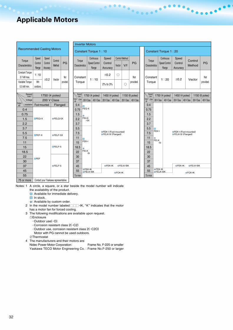
Applicable Motors
Recommended Casting Motors
Torque
Characteristics
Constant Torque
3.7 kW max.
Variable Torque
5.5 kW min.
0.4
0.75
1.5
2.2
3.7
5.5
7.5
11
15
18.5
22
30
37
45
55
75 or more
1750 (4 poles)
200 V Class
Contact your Yaskawa representative.
Foot-mounted Flanged
Speed
Control
Range
1 : 10
With
conditions.
Speed
Control
Accuracy
±0.2
Control
Method
Vector
PG
Not
provided.
Constant Torque 1 : 10
Inverter Motors
Torque
Characteristics
Constant
Torque
Continuous
Speed Control
Range
1 : 10
Speed
Control
Accuracy
±0.2
2% to 3%
Control Method
Vector
V/f
PG
Not
provided.
Constant Torque 1 : 20
Torque
Characteristics
Constant
Torque
Continuous
Speed Control
Range
1 : 20
Speed
Control
Accuracy
±0.2
Control
Method
Vector
PG
Not
provided.
0.4
0.75
1.5
2.2
3.7
5.5
7.5
11
15
18.5
22
30
37
45
55
75 or more
0.4
0.75
1.5
2.2
3.7
5.5
7.5
11
15
18.5
22
30
37
45
55
75 or more
200 V Class
1750 (4 poles)
400 V Class 200 V Class
1450 (4 poles)
400 V Class 200 V Class
1150 (6 poles)
400 V Class 200 V Class
1750 (4 poles)
400 V Class 200 V Class
1450 (4 poles)
400 V Class 200 V Class
1150 (6 poles)
400 V Class
A circle, a square, or a star beside the model number will indicate the availability of the product.
: Available for immediate delivery. : In stock. : Available by custom order.
In the model number labeled -IK, “K” indicates that the motor has a motor fan for forced cooling. The following modifications are available upon request.
Enclosure ・Outdoor use(−O) ・Corrosion resistant class 2(−C2) ・Outdoor use, corrosion resistant class 2(−C2O) Motor with PG cannot be used outdoors.
Thermostat The manufacturers and their motors are: Nidec Power Motor Corporation: Frame No. F-225 or smaller Yaskawa TECO Motor Engineering Co. : Frame No.F-250 or larger
Notes: 1
2
3
4
Speedmin-1
Voltage
Installation
Voltage
Output kW
FEQ-X
FEK-I
FEK-I
FELQ -5X
FEK-I (Foot-mounted) FELK-5I (Flanged)
FEK-I (Foot-mounted) FELK-5I (Flanged)
FELK -5I
FEK-IKFELK-5IK
FELK -5I
FEK-IKFELK-5IK
FEK-IK FELK-5IK FEK-IK FELK-5IK
FCK-IK FCK-IK
Speedmin-1
Output kW
FEQ-X FELQ-5X
FEF-X FELF-5X
FELF-5
FELF-5
FEF
Voltage
Speedmin-1
Output kW
32
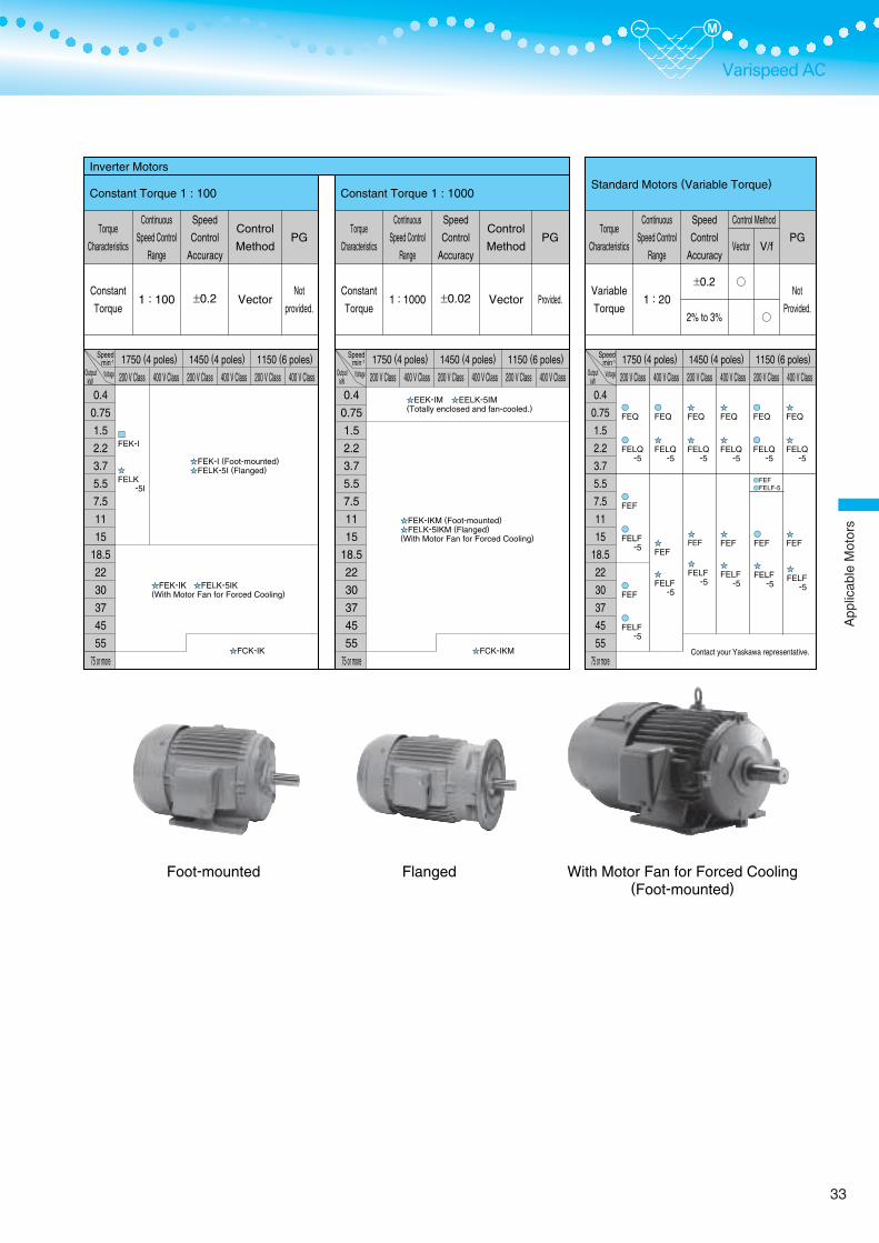
Varispeed AC
Standard Motors (Variable Torque)
Torque
Characteristics
Variable
Torque
Continuous
Speed Control
Range
1 : 20
Speed
Control
Accuracy
±0.2
2% to 3%
Control Method
Vector
V/f
PG
Not
Provided.
0.4
0.75
1.5
2.2
3.7
5.5
7.5
11
15
18.5
22
30
37
45
55
75 or more
200 V Class
1750 (4 poles)
400 V Class 200 V Class
1450 (4 poles)
400 V Class 200 V Class
1150 (6 poles)
400 V Class
Inverter Motors
Constant Torque 1 : 1000
Torque
Characteristics
Constant
Torque
Continuous
Speed Control
Range
1 : 1000
Speed
Control
Accuracy
±0.02
Control
Method
Vector
PG
Provided.
Constant Torque 1 : 100
Torque
Characteristics
Constant
Torque
Continuous
Speed Control
Range
1 : 100
Speed
Control
Accuracy
±0.2
Control
Method
Vector
PG
Not
provided.
0.4
0.75
1.5
2.2
3.7
5.5
7.5
11
15
18.5
22
30
37
45
55
75 or more
0.4
0.75
1.5
2.2
3.7
5.5
7.5
11
15
18.5
22
30
37
45
55
75 or more
200 V Class
1750 (4 poles)
400 V Class 200 V Class
1450 (4 poles)
400 V Class 200 V Class
1150 (6 poles)
400 V Class 200 V Class
1750 (4 poles)
400 V Class 200 V Class
1450 (4 poles)
400 V Class 200 V Class
1150 (6 poles)
400 V Class
Foot-mounted Flanged With Motor Fan for Forced Cooling(Foot-mounted)
FEK-I
FELK -5I
FEK-I (Foot-mounted) FELK-5I (Flanged)
FEK-IK FELK-5IK(With Motor Fan for Forced Cooling)
FCK-IK
EEK-IM EELK-5IM(Totally enclosed and fan-cooled.)
FEK-IKM (Foot-mounted) FELK-5IKM (Flanged)(With Motor Fan for Forced Cooling)
FCK-IKM
FEQ
FEQ
FELQ -5
FELQ -5
FEQ
FELQ -5
FEQ
FELQ -5
FEQ
FELQ -5
FEQ
FELQ -5
FELF -5
FELF -5
FELF -5
FEF
FEF
FEF
FEF
FEF
FELF -5
FELF -5
FEF
FELF -5
FELF -5
FEF FELF-5
FEF
Voltage
Speedmin-1
Output kW
Voltage
Speedmin-1
Output kW
Voltage
Speedmin-1
Output kW
Contact your Yaskawa representative.
33
App
licab
leM
otor
s
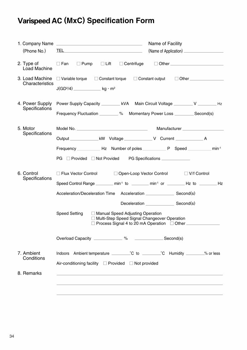
Varispeed AC (MxC) Specification Form
1. Company Name
(Phone No.)
2. Type ofLoad Machine
3. Load MachineCharacteristics
4. Power Supply
Specifications
5. Motor Specifications 6. Control
Specifications
7. AmbientConditions
8. Remarks
Fan Pump Lift Centrifuge Other Variable torque Constant torque Constant output Other
J(GD2/4) kg m2
Power Supply Capacity kVA Main Circuit Voltage V Hz
Frequency Fluctuation % Momentary Power Loss Second(s)
Model No. Manufacturer
Output kW Voltage V Current A
Frequency Hz Number of poles P Speed min-1
PG Provided Not Provided PG Specifications
Flux Vector Control Open-Loop Vector Control V/f Control Speed Control Range min-1 to min-1 or Hz to Hz Acceleration/Deceleration Time Acceleration Second(s)
Deceleration Second(s)
Speed Setting Manual Speed Adjusting Operation Multi-Step Speed Signal Changeover Operation Process Signal 4 to 20 mA Operation Other
Overload Capacity % Second(s) Indoors Ambient temperature ˚C to ˚C Humidity % or less Air-conditioning facility Provided Not provided
Name of Facility
(Name of Application)TEL
34

Service Network
19
ChicagoSan Francisco
BostonFrankfurt
Mumbai
Singapore
Bangkok
SeoulTokyo
Shanghai
Taipei
Sydney
Melbourne
North Carolina
Mexico City
Santafe De Bogota
Sao Paulo
New Jersey
Los Angels
1
4
3
65 9 10
12
14
1718
13
15 16
11
7 8
2
Headquarters+1-847-887-7303
FAX +1-847-887-7070
+52-5593-28-69 FAX +52-5651-55-73
+55-11-5071-2552 FAX +55-11-5581-8795
+57-91-635-7460 FAX +57-91-611-3872
+49-6196-569-300 FAX +49-6196-569-398
+49-6196-569-520 FAX +49-6196-888-598
See the back cover.
+82-2-784-7844
FAX +82-2-784-8495 +82-2-3775-0337
FAX +82-2-3775-0338 +82-331-200-2981
FAX +82-331-200-2970 +86-21-5385-2200
FAX +86-21-5385-3299 +86-21-6553-6060
FAX +86-21-5588-1190 +886-2-2502-5003
FAX +886-2-2505-1280 +65-6282-3003
FAX +65-6289-3003 +65-6282-1601
FAX +65-6282-3668 +66-2-693-2200
FAX +66-2-693-2204 Headquarters
+91-22-7683511 (662) FAX +91-22-7683525 Headquarters
+61-2-9748-3788 FAX +61-2-9748-3817
Region
North America
SouthAmerica
Europe
Asia
Oceania
Service Area
U.S.A
Mexico
South America
Colombia
All of Europeand South
Africa
Japan
South Korea
China
Taiwan
Singapore
Thailand
India
Australia
Service Location
Chicago (HQ)
Los AngelesNew Jersey
BostonSan Francisco, Ohio
North Carolina
Mexico City
Sao Paulo
Santafe De Bogota
Frankfurt
Tokyo, and elsewhere
Seoul
Beijing, Guangzhou,Shanghai
Taipei
Singapore
Bangkok
Mumbai
Sydney (HQ)
Melbourne
Service Agency Telephone/Fax
1
2
3
4
5
6
7
8
9
10
11
12
13
14
15
16
17
18
19
YASKAWA ELECTRIC AMERICA INC.
PILLAR MEXICANA. S.A. DE C.V.
YASKAWA ELECTRICO DO BRASIL LTDA.
VARIADORES LTD.A.
YASKAWA ELECTRIC EUROPE GmbH
YASKAWA ENGINEERING EUROPE GmbH
YASKAWA ELECTRIC CORPORATION(Manufacturing, sales)
YASKAWA ELECTRIC ENGINEERING CORPORATION(After-sales service)
YASKAWA ELECTRIC KOREA CORPORATION
YASKAWA ENGINEERING KOREA Co.
Rockwell Samsung Automation Co., Ltd.
YASKAWA ELECTRIC (SHANGHAI) Co., Ltd.
Shanghai Yaskawa-Tongji M&E Co., Ltd.
YASKAWA ELECTRIC TAIWAN Co.
YASKAWA ELECTRIC (SINGAPORE) Pte. Ltd
YASKAWA ENGINEERING ASIA-PACIFIC Pte. Ltd.
YASKAWA ELECTRIC (THAILAND) Co., Ltd.
LARSEN & TOUBRO LIMITED
ROBOTIC AUTOMATION Pty. Ltd.
35
Var
ispe
edA
C( M
xC)
Spe
cific
atio
nF
orm
/Ser
vice
Net
wor
k
Varispeed AC
YASKAWA ELECTRIC CORPORATION
IRUMA BUSINESS CENTER (SOLUTION CENTER)480, Kamifujisawa, Iruma, Saitama 358-8555, JapanPhone 81-4-2962-5696 Fax 81-4-2962-6138
YASKAWA ELECTRIC AMERICA, INC.2121 Norman Drive South, Waukegan, IL 60085, U.S.A.Phone 1-847-887-7000 Fax 1-847-887-7370
YASKAWA ELETRICO DO BRASIL LTDA.Avenida Fagundes Filho, 620 Bairro Saude-Sao Paulo-SP, Brazil CEP: 04304-000Phone 55-11-5071-2552 Fax 55-11-5581-8795
YASKAWA ELECTRIC EUROPE GmbHAm Kronberger Hang 2, 65824 Schwalbach, GermanyPhone 49-6196-569-300 Fax 49-6196-569-312
YASKAWA ELECTRIC UK LTD.1 Hunt Hill Orchardton Woods Cumbernauld, G68 9LF, United KingdomPhone 44-1236-735000 Fax 44-1236-458182
YASKAWA ELECTRIC KOREA CORPORATION7F, Doore Bldg. 24, Yeoido-dong, Youngdungpo-Ku, Seoul 150-877, KoreaPhone 82-2-784-7844 Fax 82-2-784-8495
YASKAWA ELECTRIC (SINGAPORE) PTE. LTD.151 Lorong Chuan, #04-01, New Tech Park 556741, SingaporePhone 65-6282-3003 Fax 65-6289-3003
YASKAWA ELECTRIC (SHANGHAI) CO., LTD.No.18 Xizang Zhong Road. Room 1702-1707, Harbour Ring Plaza Shanghai 200001, ChinaPhone 86-21-5385-2200 Fax 86-21-5385-3299
YASKAWA ELECTRIC (SHANGHAI) CO., LTD. BEIJING OFFICERoom 1011A, Tower W3 Oriental Plaza, No.1 East Chang An Ave.,Dong Cheng District, Beijing 100738, ChinaPhone 86-10-8518-4086 Fax 86-10-8518-4082
YASKAWA ELECTRIC TAIWAN CORPORATION9F, 16, Nanking E. Rd., Sec. 3, Taipei, TaiwanPhone 886-2-2502-5003 Fax 886-2-2505-1280
In the event that the end user of this product is to be the military and said product is to be employed in any weapons systems or the manufacture thereof, the export will fall under the relevant regulations as stipulated in the Foreign Exchange and Foreign Trade Regulations. Therefore, be sure to follow all procedures and submit all relevant documentation according to any and all rules, regulations and laws that may apply.
Specifications are subject to change without notice for ongoing product modifications and improvements.
© 2006-2007 YASKAWA ELECTRIC CORPORATION. All rights reserved.
YASKAWA
Printed on 100% recycled paperwith soybean oil ink.
LITERATURE NO. KAEP C710636 00B
07-8-9Published in Japan October 2007 06-10 1 -0